WO2012165427A1 - 呼吸検出装置 - Google Patents
呼吸検出装置 Download PDFInfo
- Publication number
- WO2012165427A1 WO2012165427A1 PCT/JP2012/063759 JP2012063759W WO2012165427A1 WO 2012165427 A1 WO2012165427 A1 WO 2012165427A1 JP 2012063759 W JP2012063759 W JP 2012063759W WO 2012165427 A1 WO2012165427 A1 WO 2012165427A1
- Authority
- WO
- WIPO (PCT)
- Prior art keywords
- abdomen
- pressure
- respiration
- subject
- reference plate
- Prior art date
- Legal status (The legal status is an assumption and is not a legal conclusion. Google has not performed a legal analysis and makes no representation as to the accuracy of the status listed.)
- Ceased
Links
Images

Classifications
-
- A—HUMAN NECESSITIES
- A61—MEDICAL OR VETERINARY SCIENCE; HYGIENE
- A61B—DIAGNOSIS; SURGERY; IDENTIFICATION
- A61B5/00—Measuring for diagnostic purposes; Identification of persons
- A61B5/103—Measuring devices for testing the shape, pattern, colour, size or movement of the body or parts thereof, for diagnostic purposes
- A61B5/11—Measuring movement of the entire body or parts thereof, e.g. head or hand tremor or mobility of a limb
- A61B5/113—Measuring movement of the entire body or parts thereof, e.g. head or hand tremor or mobility of a limb occurring during breathing
- A61B5/1135—Measuring movement of the entire body or parts thereof, e.g. head or hand tremor or mobility of a limb occurring during breathing by monitoring thoracic expansion
-
- A—HUMAN NECESSITIES
- A61—MEDICAL OR VETERINARY SCIENCE; HYGIENE
- A61B—DIAGNOSIS; SURGERY; IDENTIFICATION
- A61B2562/00—Details of sensors; Constructional details of sensor housings or probes; Accessories for sensors
- A61B2562/02—Details of sensors specially adapted for in-vivo measurements
- A61B2562/0247—Pressure sensors
Definitions
- the present invention relates to a respiration detection device that detects human respiration, and particularly to a respiration detection device that is inexpensive, comfortable to wear, and highly sensitive.
- the detection of respiration is mainly used for examination of sleep apnea syndrome.
- a thermistor attached to the lower nasal cavity or a thermal image processing of the lower nasal cavity detects a temperature change in the lower nasal cavity (Detecting respiration from changes in the volume of the lungs associated with breathing as impedance changes by wrapping a detection belt around the chest, as well as changes in carbon dioxide concentration measured by passing ultrasonic waves through the breathing air (See Patent Document 2).
- the conventional respiration detection apparatus as described above has a problem that the thermistor type is inexpensive and reliable, but the wearing feeling is bad.
- the thermal image processing method does not need to be worn, but the device is expensive and difficult to detect depending on the sleeping posture.
- the device is placed away from the subject and linked with other detection data. There is also the problem of being troublesome.
- the impedance type has a problem that the device is large and the feeling of wearing is bad.
- the ultrasonic method is cheaper than the thermal image processing method, but the device is expensive. Like the thermal image processing method, it is troublesome to link with other detection data to place the device away from the subject. There is also a problem.
- the present invention relates to an inexpensive, easy-to-wear and high-sensitivity respiration detection device that advantageously solves the problems of the conventional respiration detection device described above, and the respiration detection device of the present invention is a recess located between both ends. Facing the abdomen of the subject, a reference plate mounted on the abdomen of the subject so that both ends thereof are supported by the abdomen, A pressure sensor that contacts the abdomen and receives pressure from the abdomen, and a pressure sensor that is interposed between the reference plate and the pressure receiving plate, detects the pressure applied to the pressure receiving plate from the abdomen, and outputs it as a signal It is characterized by comprising.
- a respiratory detection device when a reference plate having a recess between both ends is attached to the subject's abdomen so that the recess is directed to the abdomen of the subject and the both ends are supported by the abdomen, A pressure receiving plate arranged so as to be movable with respect to both ends in the recess of the reference plate receives pressure from the abdomen in contact with the abdomen, and a pressure sensor inserted between the reference plate and the pressure receiving plate The pressure applied to the pressure receiving plate is detected and output as a signal.
- the pressure sensor When the subject inhales, the diaphragm becomes tense and the abdominal pressure rises. As a result, when the pressure applied to the pressure receiving plate from the abdomen also rises, the pressure sensor outputs a signal indicating the rise in the abdominal pressure and consequently the subject's inspiration. On the other hand, when the subject exhales, the diaphragm relaxes and the abdominal pressure decreases, thereby reducing the pressure applied to the pressure plate from the abdomen, and the pressure sensor indicates a decrease in the abdominal pressure, and thus the exhalation of the subject. Is output. As the pressure sensor, various types such as a strain gauge type sensor whose resistance value changes with pressure, a capacitance type sensor whose capacitance changes with pressure, and a piezo element type sensor that generates electricity with pressure are used. Can do.
- the respiration detection device of the present invention it is possible to detect the respiration of the subject with a simple and inexpensive configuration mainly including a reference plate, a pressure receiving plate, and a pressure sensor, and both ends of the reference plate are Because it is supported by the abdomen, the pressure receiving plate stably receives pressure from the abdomen between both ends of the reference plate regardless of changes in the mounting force of the reference plate, so that it is possible to accurately detect respiration and the pressure receiving plate
- the pressure applied to the pressure-receiving plate from the abdomen can be increased, and the detection sensitivity of breathing can be easily increased. be able to.
- the respiratory detection device of the present invention may further include a mounting film for mounting the reference plate on the abdomen of the subject with an adhesive on the back surface. In this way, the reference plate can be easily and reliably attached to the subject's abdomen.
- an amplification circuit that amplifies the output signal of the pressure sensor, a filter that extracts a frequency component indicating respiration from the output signal of the amplification circuit, and an output signal of the filter
- a respiration detection circuit having a comparator that outputs a respiration signal when the output signal is equal to or higher than the threshold value compared to the threshold value. In this way, it is possible to output a respiration signal that clearly indicates respiration with a compact and inexpensive configuration.
- the respiratory detection device of the present invention further includes a three-axis acceleration sensor that measures a change in the posture of the abdomen of the subject, a data logger, and a battery for supplying power, and the data logger indicates real time.
- a real-time clock, a memory for storing data in a readable manner, a respiratory signal from the comparator, and a body position change signal from the three-axis acceleration sensor are associated with the real-time signal from the real-time clock in the memory.
- a central processing unit for continuous storage.
- the breath detection circuit and the data logger with the power supply from the battery during the sleep of the subject, the presence or absence of the subject's breathing and the change in the abdominal body position over time during sleep Can be recorded automatically, and by analyzing the respiratory data, body position change data, and real-time data read from the data logger memory after waking up, the sleep apnea syndrome test Can be easily performed.
- FIG. 1 is a cross-sectional view showing a pad portion of a respiration sensor as an embodiment of the respiration detection apparatus of the present invention
- FIG. 2 is a configuration diagram showing a respiration detection circuit of the respiration sensor of the above embodiment.
- symbol A indicates the abdomen of the subject
- 1 indicates the pad portion
- 2 indicates the respiration detection circuit.
- the cross-sectional view of the pad portion 1 of the respiratory sensor of this embodiment is such that the concave portion 3b positioned between the peripheral portions 3a as both ends is directed toward the abdomen A of the subject, and the peripheral portion 3a is
- an inverted dish-shaped circular reference plate 3 that is attached to the subject's abdomen A so as to be supported by the abdomen A, and a gap that is movable with respect to the peripheral portion 3a is provided in the recess 3b of the reference plate 3.
- the pressure applied to the pressure receiving plate 4 from the abdominal part A by being interposed between the disc-shaped pressure receiving plate 4 that is disposed and abuts the abdominal part A and receives pressure from the abdominal part A, and the reference plate 3 and the pressure receiving plate 4.
- a circular mounting film 6 for mounting the reference plate 3 on the abdomen A of the subject with an annular adhesive 6a around the periphery of the back surface.
- the reference plate 3 is, for example, about 3 to 6 cm in diameter. Thereby, the wearing feeling to the abdominal part A can be made favorable.
- the pressure sensor 5 includes, for example, an elastic plate (not shown) whose periphery is coupled to one of the reference plate 3 and the pressure receiving plate 4 and whose center is coupled to the other of the reference plate 3 and the pressure receiving plate 4, and the elastic plate.
- the four strain gauges 5a shown in FIG. 2 are attached to the surface of the substrate in such a manner that each side of a square centered on the center of the surface is bridge-connected to each other. Thereby, the pressure applied from the abdomen A to the pressure receiving plate 4 can be measured with high accuracy.
- the respiration detection circuit 2 of the respiration sensor of this embodiment is connected to the four strain gauges 5a of the pressure sensor 5 via four wires not shown in FIG.
- the four connection points of the four strain gauges 5a that are bridge-connected to each other by one of the four wirings one of the two opposing connection points is connected to the ground of the respiration detection circuit 2, and the other is a resistance.
- 7 is connected to a power source (not shown) composed of, for example, a battery of the respiration detection circuit 2 via 7, and one of the other two opposing connection points is connected to the + input terminal of the normal amplifier 8 of the respiration detection circuit 2. The other is connected to the negative input terminal of the amplifier 8.
- the output terminal of the amplifier 8 is connected to the + input terminal of a normal comparator 11 through a normal high-pass filter 9 and a low-pass filter 10, and the negative input terminal of the comparator 11 is connected to the variable resistor 12 connected to the power source.
- a changeable reference voltage as a threshold is supplied, and the output terminal and the ground terminal of the comparator 11 are used as the output terminal 13 of the respiration detection circuit 2.
- the respiration detection circuit 2 may be housed in a case (not shown) that is separate from the pad unit 1 and connected to the pressure sensor 5 in the pad unit 1 by the above-described wiring. In addition, it is accommodated in the pressure receiving plate 4 having a hollow inside, or is mounted between the reference plate 3 and the pressure receiving plate 4 and mounted on the pad portion 1 to expose the output terminal 13 to the outside. Also good.
- the reference plate 3 having the recess 3b between the peripheral portions 3a is directed toward the subject's abdomen A so that the peripheral portion 3a is supported by the abdomen A.
- a pressure receiving plate 4 disposed in the recess 3b of the reference plate 3 so as to be movable with respect to the peripheral edge 3a receives the pressure P due to the abdominal pressure from the abdominal portion A in contact with the abdominal portion A, and the reference plate 3 and the pressure receiving plate 4
- the pressure sensor 5 inserted between the two detects a pressure P applied to the pressure receiving plate 4 from the abdomen A and outputs it as an electrical signal.
- an elastic plate having the periphery of the pressure sensor 5 coupled to one of the reference plate 3 and the pressure receiving plate 4 and the center coupled to the other of the reference plate 3 and the pressure receiving plate 4 extends from the abdomen A. Since the elastic deformation is caused by the pressure P applied to the pressure receiving plate 4, and the four strain gauges 5 a are also elastically deformed and the resistance value changes with the elastic deformation of the elastic plate, the pressure P applied to the pressure receiving plate 4 from the abdomen A Accordingly, the output voltage of the bridge connection of the four strain gauges 5a fed from the power source changes.
- the pressure sensor 5 increases the abdominal pressure and consequently the inhalation of the subject.
- the pressure sensor 5 detects the abdominal pressure. A signal indicating the decrease and the expiration of the subject is output.
- the respiration of the subject can be detected with a simple and inexpensive configuration mainly including the reference plate 3, the pressure receiving plate 4 and the pressure sensor 5, and the reference plate 3 Since the peripheral edge portion 3a of the reference plate 3 is supported by the abdominal portion A, the pressure receiving plate 4 receives the pressure P stably from the abdominal portion A between the peripheral edge portions 3a of the reference plate 3 regardless of changes in the mounting force of the reference plate 3.
- the pressure receiving plate 4 can be detected accurately, and by increasing the area of the pressure receiving plate 4, the pressure P applied to the pressure receiving plate 4 from the abdominal part A can be increased to easily increase the detection sensitivity of respiration, and the reference plate Since 3 is only worn on the abdomen, the wearing feeling of the subject can be made good.
- the reference plate 3 since the mounting film 6 for mounting the reference plate 3 on the abdomen A of the subject is further provided by the adhesive 6a on the back surface, the reference plate 3 can be easily attached to the abdomen A of the subject. And can be securely attached.
- the respiration detection circuit 2 amplifies the output signal of the pressure sensor 5 by the amplifier 8 as an amplification circuit
- the high-pass filter 9 For example, low-frequency ground noise of 0.07 Hz or less caused by the posture change of the subject is removed, and then noise exceeding 0.6 Hz caused by ambient noise or utterance is removed by the low-pass filter 10 to breathe.
- the output signal of the low-pass filter 10 is compared with a threshold value that is appropriately set by a breathing experiment using the variable resistor 12 by the comparator 11.
- the comparator 11 since the comparator 11 outputs a breathing signal indicating that the subject has breathed to the output terminal 13, Pact and inexpensive configuration, it is possible to output a respiration signal clearly indicating the respiration.
- FIG. 3 is a cross-sectional view showing another embodiment of the respiration detection device of the present invention
- FIG. 4 is a block diagram showing the configuration of the respiration detection device of the embodiment.
- the respiration detection device of this embodiment Is a combination of the respiration sensor of the previous embodiment and a data logger that automatically records data. In the figure, like the previous embodiment shown in FIGS. Is shown.
- the respiration detecting device of this embodiment is provided with a pad portion 1 as shown in FIG. 3, and the pad portion 1 is located between the peripheral portions 3a as both ends as in the previous embodiment.
- an inverted dish-shaped circular reference plate 3 mounted on the subject's abdomen so that the peripheral part 3a is supported by the abdomen with the recess 3b facing the abdomen, and the recess 3b of the reference plate 3 Is arranged with a gap that is movable with respect to the peripheral edge portion 3a so as to contact the abdomen, and is interposed between the disc-shaped pressure receiving plate 4 that receives pressure from the abdomen, and the reference plate 3 and the pressure receiving plate 4.
- a pressure sensor 5 that detects the pressure applied to the pressure receiving plate 4 from the abdomen and outputs it as a signal, and a circular mounting film (not shown) that mounts the reference plate 3 on the abdomen of the subject with an annular adhesive around the back surface And the reference plate 3 And comprises an elastic sealing membrane 14 of for example rubber ring for sealing the pressure sensor 5 is stretched from sweat or the like between the periphery of the edge portion 3a and the pressure receiving plate 4.
- the respiratory detection device of this embodiment has a hollow inside of the pressure receiving plate 4 of the pad portion 1, and the pressure receiving plate 4 is provided with a lid that can be opened and closed.
- a piezoresistive normal three-axis acceleration sensor 15 for measuring a change in the posture of the abdomen of the subject and a data logger 16 are accommodated as shown in FIG.
- a normal button battery 17 as a battery for supplying power to the respiration detection circuit 2, the triaxial acceleration sensor 15, and the data logger 16 is accommodated.
- the data logger 16 here is a real time clock 18 which is a normal time measuring circuit showing real time, a normal memory 19 such as a RAM for storing data so as to be readable, and a respiration signal from the comparator 11 of the respiration detecting circuit 2. And a normal central processing unit (CPU) 20 that continuously stores the posture change signal from the three-axis acceleration sensor 15 in the memory 19 in association with the real-time signal from the real-time clock 18. .
- CPU central processing unit
- the respiration detection circuit 2 and the data logger 16 are supplied with power from the button battery 17 during the sleep of the subject. For example, it is possible to automatically record the presence or absence of the subject's breathing and the presence or absence of a change in the abdominal position along the passage of time during sleep for about 10 hours. By analyzing the respiration data, the body position change data, and the real-time data read from the memory, the sleep apnea syndrome can be easily examined.
- the shape of the reference plate 3 is reversed. It is not limited to the circular dish shape, but may be an inverted square dish shape, only the opposite ends corresponding to the two opposite sides of the four sides of the quadrangle may protrude in the thickness direction, and a recess may be formed between them. May be formed by projecting in the thickness direction only at the corners of the polygon including the triangle or at the center of each side and forming a recess therebetween.
- the shape of the pressure receiving plate 4 is not limited to the disc shape, but may be a polygon corresponding to the shape of the concave portion of the reference plate 3.
- the output signal of the respiratory sensor of the above embodiment is output from an electronic thermometer, or from a blood oxygen saturation sensor such as a pulse oximeter, instead of or in addition to the output signal of the triaxial acceleration sensor. You may record to a data logger with a signal etc.
- the respiration detection device of the present invention it is possible to detect the respiration of the subject with a simple and inexpensive configuration mainly including a reference plate, a pressure receiving plate, and a pressure sensor, and both ends of the reference plate are abdominal. Since the pressure receiving plate receives stable pressure from the abdomen between both ends of the reference plate regardless of changes in the mounting force of the reference plate, it is possible to accurately detect respiration, and By increasing the area, the pressure applied to the pressure receiving plate from the abdomen can be increased to easily increase the detection sensitivity of breathing, and only the reference plate is attached to the abdomen, so that the feeling of wearing of the subject is improved Can do.
Landscapes
- Health & Medical Sciences (AREA)
- Life Sciences & Earth Sciences (AREA)
- Engineering & Computer Science (AREA)
- Medical Informatics (AREA)
- Physics & Mathematics (AREA)
- Dentistry (AREA)
- Biophysics (AREA)
- Pathology (AREA)
- Physiology (AREA)
- Biomedical Technology (AREA)
- Heart & Thoracic Surgery (AREA)
- Oral & Maxillofacial Surgery (AREA)
- Molecular Biology (AREA)
- Surgery (AREA)
- Animal Behavior & Ethology (AREA)
- General Health & Medical Sciences (AREA)
- Public Health (AREA)
- Veterinary Medicine (AREA)
- Measurement Of The Respiration, Hearing Ability, Form, And Blood Characteristics Of Living Organisms (AREA)
Abstract
【課題】安価で装着感が良く高感度な呼吸検出装置を提供することにある。 【解決手段】両端部の間に位置する凹部を被験者の腹部Aに向けて、その両端部が腹部に支持されるように被験者の腹部に装着される基準板3と、前記基準板の前記凹部内に前記両端部に対し移動可能に配置されて前記腹部に当接し、その腹部から圧力Pを受ける受圧板4と、前記基準板と前記受圧板との間に介挿されて、前記腹部から前記受圧板に加わる圧力を検出する圧力センサ5と、を具えることを特徴とする呼吸検出装置である。
Description
この発明は、人の呼吸を検出する呼吸検出装置に関し、特には安価で装着感が良く高感度な呼吸検出装置に関するものである。
呼吸の検出は、主に睡眠時無呼吸症候群の検査に用いられ、従来の呼吸検出装置としては例えば、鼻腔下部に取り付けるサーミスタあるいは鼻腔下部の熱画像処理により鼻腔下部の温度変化を検出するもの(特許文献1参照)や、胸部に検出ベルトを巻いて呼吸に伴う肺の体積変化をインピーダンス変化として検出するもの、さらには超音波を呼吸気に通して計測した炭酸ガス濃度の変化から呼吸を検出するもの(特許文献2参照)が知られている。
しかしながら上述の如き従来の呼吸検出装置は、サーミスタ方式のものでは、安価で確実であるが装着感が悪いという問題がある。また、熱画像処理方式のものでは、装着の必要はないが装置が高価で、寝姿勢によっては検出が難しいという問題があり、装置を被検者から離して置くため他の検出データとリンクさせるのが面倒という問題もある。
さらに、インピーダンス方式のものでは、装置が大掛かりであり、装着感が悪いという問題もある。そして、超音波方式のものでは、熱画像処理方式よりは安いものの装置が高価であり、熱画像処理方式と同様に装置を被検者から離して置くため他の検出データとリンクさせるのが面倒という問題もある。
この発明は、上記従来の呼吸検出装置の課題を有利に解決する安価で装着感が良く高感度な呼吸検出装置に関するものであり、この発明の呼吸検出装置は、両端部の間に位置する凹部を被験者の腹部に向けて、その両端部が腹部に支持されるように被験者の腹部に装着される基準板と、前記基準板の前記凹部内に前記両端部に対し移動可能に配置されて前記腹部に当接し、その腹部から圧力を受ける受圧板と、前記基準板と前記受圧板との間に介挿されて、前記腹部から前記受圧板に加わる圧力を検出して信号として出力する圧力センサと、を具えることを特徴とするものである。
かかる呼吸検出装置にあっては、両端部の間に凹部を有する基準板を、その凹部を被験者の腹部に向けて、その両端部が腹部に支持されるように被験者の腹部に装着すると、その基準板の凹部内に両端部に対し移動可能に配置された受圧板が、腹部に当接して腹部から圧力を受け、これら基準板と受圧板との間に介挿された圧力センサが、腹部から受圧板に加わる圧力を検出して信号として出力する。
それゆえ、被験者の吸気の際に横隔膜が緊張して腹圧が上昇し、これにより腹部から受圧板に加わる圧力も上昇すると、圧力センサがその腹圧の上昇ひいては被験者の吸気を示す信号を出力し、その一方、被験者の呼気の際に横隔膜が弛緩して腹圧が低下し、これにより腹部から受圧板に加わる圧力も低下すると、圧力センサがその腹圧の低下ひいては被験者の呼気を示す信号を出力する。ここにおける圧力センサとしては、例えば圧力により抵抗値が変化する歪ゲージ式センサ、圧力により静電容量が変化する静電容量式センサ、圧力により発電するピエゾ素子式センサ等、種々のものを用いることができる。
従って、この発明の呼吸検出装置によれば、主として基準板と受圧板と圧力センサとを具えてなる簡易かつ安価な構成で被験者の呼吸を検出することができ、また、基準板の両端部が腹部に支持されているため基準板の装着力の変化にかかわらず受圧板は基準板の両端部間の腹部から安定して圧力を受けるので、呼吸を正確に検出することができ、しかも受圧板の面積を大きくすることで、腹部から受圧板に加わる圧力を大きくして呼吸の検出感度を容易に高めることができ、そして基準板を腹部に装着するだけなので、被験者の装着感を良好ならしめることができる。
なお、この発明の呼吸検出装置においては、裏面に有する粘着剤によって前記基準板を被験者の腹部に装着する装着フィルムをさらに具えていても良い。このようにすれば、基準板を被験者の腹部に容易にかつ確実に装着することができる。
また、この発明の呼吸検出装置においては、前記圧力センサの出力信号を増幅する増幅回路と、前記増幅回路の出力信号から呼吸を示す周波数成分を抽出するフィルタと、前記フィルタの出力信号を所定の閾値と比較してその出力信号が前記閾値以上の場合に呼吸信号を出力するコンパレータと、を有する呼吸検出回路をさらに具えていても良い。このようにすれば、コンパクトかつ安価な構成で、呼吸を明確に示す呼吸信号を出力することができる。
さらに、この発明の呼吸検出装置においては、被験者の腹部の体位変化を計測する3軸加速度センサと、データロガーと、電源供給用のバッテリと、をさらに具え、前記データロガーは、実時間を示すリアルタイムクロックと、データを読出し可能に記憶するメモリと、前記コンパレータからの呼吸信号と、前記3軸加速度センサからの体位変化信号とを、前記リアルタイムクロックからの実時間信号と対応させて前記メモリに継続的に記憶させる中央処理ユニットと、を有していても良い。このようにすれば、例えば被験者の睡眠中に呼吸検出回路およびデータロガーをバッテリからの電源供給で作動させて、睡眠中の時間経過に沿って被験者の呼吸の有無と腹部の体位変化の有無とを自動的に記録することができるので、被験者の起床後にデータロガーのメモリから読み出した呼吸データと体位変化データと実時間データとを互いに対応させて解析することで、睡眠時無呼吸症候群の検査を容易に行うことができる。
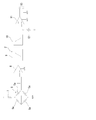
以下、本発明の実施の形態を実施例によって、図面に基づき詳細に説明する。ここに図1は、この発明の呼吸検出装置の一実施例としての呼吸センサのパッド部を示す断面図、また図2は、上記実施例の呼吸センサの呼吸検出回路を示す構成図であり、図中符号Aは被験者の腹部、1は上記パッド部、2は上記呼吸検出回路を示している。
この実施例の呼吸センサのパッド部1は、図1にその断面を示すように、両端部としての周縁部3aの間に位置する凹部3bを被験者の腹部Aに向けて、その周縁部3aが腹部Aに支持されるように被験者の腹部Aに装着される例えば裏返しの皿状の円形の基準板3と、その基準板3の凹部3b内に周縁部3aに対し移動可能な隙間を空けて配置されて腹部Aに当接し、その腹部Aから圧力を受ける円板状の受圧板4と、基準板3と受圧板4との間に介挿されて、腹部Aから受圧板4に加わる圧力を検出して信号として出力する圧力センサ5と、裏面の周辺部に環状に有する粘着剤6aによって基準板3を被験者の腹部Aに装着する円形の装着フィルム6とを具えている。
ここで、基準板3は例えば、直径3~6cm程度の大きさとする。これにより腹部Aへの装着感を良好にすることができる。また、圧力センサ5は例えば、周囲を基準板3と受圧板4との一方に結合されると共に中央を基準板3と受圧板4との他方に結合された図示しない弾性板と、その弾性板の表面にその中央を中心とした正方形の各辺をなすように貼り付けられて互いにブリッジ接続された、図2に示す4枚の歪ゲージ5aとで構成する。これにより、受圧板4に腹部Aから加わる圧力を高精度に計測することができる。
また、この実施例の呼吸センサの呼吸検出回路2は図2に示すように、図1では図示しない4本の配線を介して、上記圧力センサ5の4枚の歪ゲージ5aと接続されており、その4本の配線により、互いにブリッジ接続された4枚の歪ゲージ5aの4つの接続点のうちの1組の対抗する2つの接続点の一方は呼吸検出回路2のグラウンドに、他方は抵抗7を介して呼吸検出回路2の例えば電池からなる図示しない電源にそれぞれ接続され、他の1組の対抗する2つの接続点の一方は呼吸検出回路2の通常のアンプ8の+入力端子に、他方はそのアンプ8の-入力端子にそれぞれ接続されている。
アンプ8の出力端子は通常のハイパスフィルタ9およびローパスフィルタ10を介して通常のコンパレータ11の+入力端子に接続され、そのコンパレータ11の-入力端子には、上記電源に接続された可変抵抗12から閾値としての、変更可能な基準電圧が供給され、コンパレータ11の出力端子とグラウンド端子とが、呼吸検出回路2の出力端子13とされている。
なお、呼吸検出回路2は、パッド部1と別体の図示しないケースに収容して、パッド部1内の圧力センサ5と上記配線で接続しても良いが、後述する他の実施例と同様に、内部を空洞にした受圧板4内に収容し、あるいは基準板3と受圧板4との間等に収容することでパッド部1に搭載して、出力端子13を外部に露出させることとしても良い。
この実施例の呼吸センサにあっては、周縁部3aの間に凹部3bを有する基準板3を、その凹部3bを被験者の腹部Aに向けて、その周縁部3aが腹部Aに支持されるように腹部Aに乗せ、その基準板3の上から装着フィルム6を被せて、装着フィルム6の裏面の周辺部に環状に有する粘着剤6aによって基準板3を被験者の腹部Aに装着固定すると、その基準板3の凹部3b内に周縁部3aに対し移動可能に配置された受圧板4が、腹部Aに当接して腹部Aから腹圧による圧力Pを受け、これら基準板3と受圧板4との間に介挿された圧力センサ5が、腹部Aから受圧板4に加わる圧力Pを検出して電気信号として出力する。
すなわち具体的には圧力センサ5の、周囲を基準板3と受圧板4との一方に結合されると共に中央を基準板3と受圧板4との他方に結合された弾性板が、腹部Aから受圧板4に加わる圧力Pによって弾性変形し、その弾性板の弾性変形に伴って4枚の歪ゲージ5aもそれぞれ弾性変形して抵抗値が変化するので、腹部Aから受圧板4に加わる圧力Pに応じて、電源から給電されたその4枚の歪ゲージ5aのブリッジ接続の出力電圧が変化することになる。
それゆえ、被験者の吸気の際に横隔膜が緊張して腹圧が上昇し、これにより腹部Aから受圧板4に加わる圧力Pも上昇すると、圧力センサ5がその腹圧の上昇ひいては被験者の吸気を示す信号を出力し、その一方、被験者の呼気の際に横隔膜が弛緩して腹圧が低下し、これにより腹部Aから受圧板4に加わる圧力Pも低下すると、圧力センサ5がその腹圧の低下ひいては被験者の呼気を示す信号を出力する。
従って、この実施例の呼吸センサによれば、主として基準板3と受圧板4と圧力センサ5とを具えてなる簡易かつ安価な構成で被験者の呼吸を検出することができ、また、基準板3の周縁部3aが腹部Aに支持されているため基準板3の装着力の変化にかかわらず受圧板4は基準板3の周縁部3a間の腹部Aから安定して圧力Pを受けるので、呼吸を正確に検出することができ、しかも受圧板4の面積を大きくすることで、腹部Aから受圧板4に加わる圧力Pを大きくして呼吸の検出感度を容易に高めることができ、そして基準板3を腹部に装着するだけなので、被験者の装着感を良好ならしめることができる。
しかも、この実施例の呼吸センサによれば、裏面に有する粘着剤6aによって基準板3を被験者の腹部Aに装着する装着フィルム6をさらに具えているので、基準板3を被験者の腹部Aに容易にかつ確実に装着することができる。
そして、この実施例の呼吸センサによれば、呼吸検出回路2が、圧力センサ5の出力信号を増幅回路としてのアンプ8で増幅した後、そのアンプ8の出力信号から、先ずハイパスフィルタ9により、被験者の姿勢変化等に起因する例えば0.07Hz以下の低周波のグランドノイズを除去し、次いでローパスフィルタ10により、周囲の騒音や発声等に起因する例えば0.6Hzを超えるノイズを除去して呼吸を示す周波数成分を抽出し、その後、ローパスフィルタ10の出力信号をコンパレータ11で、可変抵抗12を用いて予め呼吸の実験により適宜設定した閾値と比較して、ローパスフィルタ10の出力信号がその閾値以上の場合に、コンパレータ11から出力端子13に、被験者が呼吸したことを示す呼吸信号を出力するので、コンパクトかつ安価な構成で、呼吸を明確に示す呼吸信号を出力することができる。
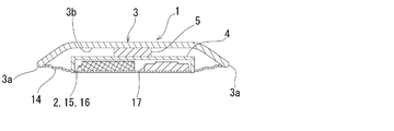
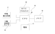
図3は、この発明の呼吸検出装置の他の一実施例を示す断面図、また図4は、その実施例の呼吸検出装置の構成を示すブロック線図であり、この実施例の呼吸検出装置は、先の実施例の呼吸センサに、データを自動的に記録するデータロガーを組み合わせたものであるので、図中、図1,2に示す先の実施例と同様に部分はそれと同一の符号にて示す。
すなわち、この実施例の呼吸検出装置は、図3に示すようにパッド部1を具えており、そのパッド部1は先の実施例と同様に、両端部としての周縁部3aの間に位置する凹部3bを被験者の腹部に向けて、その周縁部3aが腹部に支持されるように被験者の腹部に装着される例えば裏返しの皿状の円形の基準板3と、その基準板3の凹部3b内に周縁部3aに対し移動可能な隙間を空けて配置されて腹部に当接し、その腹部から圧力を受ける円板状の受圧板4と、基準板3と受圧板4との間に介挿されて、腹部から受圧板4に加わる圧力を検出して信号として出力する圧力センサ5と、裏面の周辺部に環状に有する粘着剤によって基準板3を被験者の腹部に装着する図示しない円形の装着フィルムとを具えるとともに、さらに、基準板3の周縁部3aと受圧板4の周縁部との間に張り渡されて圧力センサ5を汗等からシールする環状の例えばゴム製の弾性シール膜14を具えている。
また、この実施例の呼吸検出装置は、図3に示すように、パッド部1の受圧板4の内部が空洞にされていて、その受圧板4の開閉可能な蓋が設けられた空洞内に、先の実施例と同様の呼吸検出回路2を収容するとともに、図4に示すように、被験者の腹部の体位変化を計測する例えばピエゾ抵抗式の通常の3軸加速度センサ15と、データロガー16と、それら呼吸検出回路2と3軸加速度センサ15とデータロガー16とへの電源供給用のバッテリとしての例えば通常のボタン電池17とを収容して具えている。
ここにおけるデータロガー16は、実時間を示す通常の計時回路であるリアルタイムクロック18と、データを読出し可能に記憶する例えばRAM等の通常のメモリ19と、呼吸検出回路2のコンパレータ11からの呼吸信号と、3軸加速度センサ15からの体位変化信号とを、リアルタイムクロック18からの実時間信号と対応させてメモリ19に継続的に記憶させる通常の中央処理ユニット(CPU)20とを有している。
この実施例の呼吸検出装置によれば、先の実施例と同様の作用効果を奏し得るのに加えて、例えば被験者の睡眠中に呼吸検出回路2およびデータロガー16をボタン電池17からの電源供給で例えば10時間程度連続的に作動させて、睡眠中の時間経過に沿って被験者の呼吸の有無と腹部の体位変化の有無とを自動的に記録することができるので、被験者の起床後にデータロガーのメモリから読み出した呼吸データと体位変化データと実時間データとを互いに対応させて解析することで、睡眠時無呼吸症候群の検査を容易に行うことができる。
以上、図示例に基づき説明したが、この発明は上述の例に限定されるものでなく、特許請求の範囲の記載範囲内で適宜変更し得るものであり、例えば、基準板3の形状は裏返しの円形の皿状に限られず裏返しの角皿状でも良く、四角形の四辺のうち対向する2辺に相当する両端部だけ厚み方向に突出してそれらの間に凹部を形成していても良く、さらには三角形を含む多角形の各隅部分あるいは各辺の中央部分だけ厚み方向に突出してそれらの間に凹部を形成していても良い。そして受圧板4の形状も円板状に限られず、基準板3の凹部の形状に対応する多角形でも良い。
さらに、基準板3を腹部Aに装着するものは,粘着剤6aを有する装着パッド6に限られず、医療用の粘着テープ等でも良く、また圧力センサ5は、歪ゲージ5aを用いたものに限られず、静電容量式やピエゾ素子式等のものでも良い。
そして、上記実施例の呼吸センサの出力信号は、3軸加速度センサの出力信号に代えてまたは加えて、電子式体温計からの出力信号や、パルスオキシメーターの如き血中酸素飽和度センサからの出力信号等と一緒にデータロガーに記録しても良い。
かくしてこの発明の呼吸検出装置によれば、主として基準板と受圧板と圧力センサとを具えてなる簡易かつ安価な構成で被験者の呼吸を検出することができ、また、基準板の両端部が腹部に支持されているため基準板の装着力の変化にかかわらず受圧板は基準板の両端部間の腹部から安定して圧力を受けるので、呼吸を正確に検出することができ、しかも受圧板の面積を大きくすることで、腹部から受圧板に加わる圧力を大きくして呼吸の検出感度を容易に高めることができ、そして基準板を腹部に装着するだけなので、被験者の装着感を良好ならしめることができる。
1 パッド部
2 呼吸検出回路
3 基準板
3a 周縁部
3b 凹部
4 受圧板
5 圧力センサ
5a 歪ゲージ
6 装着フィルム6
6a 粘着剤
7 抵抗
8 アンプ
9 ハイパスフィルタ
10 ローパスフィルタ
11 コンパレータ
12 可変抵抗
13 出力端子
14 弾性シール膜
15 3軸加速度センサ
16 データロガー
17 ボタン電池
18 リアルタイムクロック
19 メモリ
20 中央処理ユニット(CPU)
A 腹部
P 圧力
2 呼吸検出回路
3 基準板
3a 周縁部
3b 凹部
4 受圧板
5 圧力センサ
5a 歪ゲージ
6 装着フィルム6
6a 粘着剤
7 抵抗
8 アンプ
9 ハイパスフィルタ
10 ローパスフィルタ
11 コンパレータ
12 可変抵抗
13 出力端子
14 弾性シール膜
15 3軸加速度センサ
16 データロガー
17 ボタン電池
18 リアルタイムクロック
19 メモリ
20 中央処理ユニット(CPU)
A 腹部
P 圧力
Claims (4)
- 両端部の間に位置する凹部を被験者の腹部に向けて、その両端部が腹部に支持されるように被験者の腹部に装着される基準板と、
前記基準板の前記凹部内に前記両端部に対し移動可能に配置されて前記腹部に当接し、その腹部から圧力を受ける受圧板と、
前記基準板と前記受圧板との間に介挿されて、前記腹部から前記受圧板に加わる圧力を検出して信号として出力する圧力センサと、
を具えることを特徴とする呼吸検出装置。 - 裏面に有する粘着剤によって前記基準板を被験者の腹部に装着する装着フィルムをさらに具えることを特徴とする、請求項1記載の呼吸検出装置。
- 前記圧力センサの出力信号を増幅する増幅回路と、
前記増幅回路の出力信号から呼吸を示す周波数成分を抽出するフィルタと、
前記フィルタの出力信号を所定の閾値と比較してその出力信号が前記閾値以上の場合に呼吸信号を出力するコンパレータと、
を有する呼吸検出回路をさらに具えることを特徴とする、請求項1または2記載の呼吸検出装置。 - 被験者の腹部の体位変化を計測する3軸加速度センサと、
データロガーと、
電源供給用のバッテリと、
をさらに具え、
前記データロガーは、
実時間を示すリアルタイムクロックと、
データを読出し可能に記憶するメモリと、
前記コンパレータからの呼吸信号と、前記3軸加速度センサからの体位変化信号とを、前記リアルタイムクロックからの実時間信号と対応させて前記メモリに継続的に記憶させる中央処理ユニットと、
を有することを特徴とする、請求項3記載の呼吸検出装置。
Applications Claiming Priority (2)
| Application Number | Priority Date | Filing Date | Title |
|---|---|---|---|
| JP2011-125655 | 2011-06-03 | ||
| JP2011125655 | 2011-06-03 |
Publications (1)
| Publication Number | Publication Date |
|---|---|
| WO2012165427A1 true WO2012165427A1 (ja) | 2012-12-06 |
Family
ID=47259281
Family Applications (1)
| Application Number | Title | Priority Date | Filing Date |
|---|---|---|---|
| PCT/JP2012/063759 Ceased WO2012165427A1 (ja) | 2011-06-03 | 2012-05-29 | 呼吸検出装置 |
Country Status (2)
| Country | Link |
|---|---|
| JP (1) | JPWO2012165427A1 (ja) |
| WO (1) | WO2012165427A1 (ja) |
Cited By (5)
| Publication number | Priority date | Publication date | Assignee | Title |
|---|---|---|---|---|
| CN107997768A (zh) * | 2018-01-02 | 2018-05-08 | 北京津发科技股份有限公司 | 一种穿戴式呼吸测量装置和呼吸测量方法 |
| JP2019097823A (ja) * | 2017-11-30 | 2019-06-24 | ヤマハ株式会社 | 生体センサ |
| CN114271808A (zh) * | 2021-11-06 | 2022-04-05 | 重庆大学 | 一种穿戴式呼吸生理参数测量装置 |
| CN116616774A (zh) * | 2023-07-21 | 2023-08-22 | 苏州恒瑞迦俐生生物医药科技有限公司 | 呼吸压力监测系统 |
| WO2024157027A1 (en) * | 2023-01-26 | 2024-08-02 | Rosier Physiotherapy And Movement Studio Ltd | An apparatus and method for measuring intra-abdominal pressure |
Citations (2)
| Publication number | Priority date | Publication date | Assignee | Title |
|---|---|---|---|---|
| JPH0670702U (ja) * | 1993-03-19 | 1994-10-04 | 日本光電工業株式会社 | マルチセンサ |
| JP2001299712A (ja) * | 2000-04-19 | 2001-10-30 | Advanced Medical Kk | 長時間生体モニタ |
-
2012
- 2012-05-29 WO PCT/JP2012/063759 patent/WO2012165427A1/ja not_active Ceased
- 2012-05-29 JP JP2013518102A patent/JPWO2012165427A1/ja active Pending
Patent Citations (2)
| Publication number | Priority date | Publication date | Assignee | Title |
|---|---|---|---|---|
| JPH0670702U (ja) * | 1993-03-19 | 1994-10-04 | 日本光電工業株式会社 | マルチセンサ |
| JP2001299712A (ja) * | 2000-04-19 | 2001-10-30 | Advanced Medical Kk | 長時間生体モニタ |
Cited By (8)
| Publication number | Priority date | Publication date | Assignee | Title |
|---|---|---|---|---|
| JP2019097823A (ja) * | 2017-11-30 | 2019-06-24 | ヤマハ株式会社 | 生体センサ |
| JP7143585B2 (ja) | 2017-11-30 | 2022-09-29 | ヤマハ株式会社 | 生体センサ |
| CN107997768A (zh) * | 2018-01-02 | 2018-05-08 | 北京津发科技股份有限公司 | 一种穿戴式呼吸测量装置和呼吸测量方法 |
| CN107997768B (zh) * | 2018-01-02 | 2024-06-21 | 北京津发科技股份有限公司 | 一种穿戴式呼吸测量装置和呼吸测量方法 |
| CN114271808A (zh) * | 2021-11-06 | 2022-04-05 | 重庆大学 | 一种穿戴式呼吸生理参数测量装置 |
| CN114271808B (zh) * | 2021-11-06 | 2025-03-14 | 重庆大学 | 一种穿戴式呼吸生理参数测量装置 |
| WO2024157027A1 (en) * | 2023-01-26 | 2024-08-02 | Rosier Physiotherapy And Movement Studio Ltd | An apparatus and method for measuring intra-abdominal pressure |
| CN116616774A (zh) * | 2023-07-21 | 2023-08-22 | 苏州恒瑞迦俐生生物医药科技有限公司 | 呼吸压力监测系统 |
Also Published As
| Publication number | Publication date |
|---|---|
| JPWO2012165427A1 (ja) | 2015-02-23 |
Similar Documents
| Publication | Publication Date | Title |
|---|---|---|
| JP3737121B2 (ja) | 圧力および温度波形解析のための装置および方法 | |
| Cao et al. | A wireless portable system with microsensors for monitoring respiratory diseases | |
| US9192351B1 (en) | Acoustic respiratory monitoring sensor with probe-off detection | |
| US20180338743A1 (en) | Acoustic detection mask systems and/or methods | |
| CN107997768B (zh) | 一种穿戴式呼吸测量装置和呼吸测量方法 | |
| WO2005034750A1 (ja) | 睡眠時呼吸状態測定装置 | |
| WO2018130036A1 (zh) | 一种多传感器心肺耦合睡眠质量检测系统及其检测方法 | |
| JP2007202939A (ja) | 生体情報検出装置 | |
| WO2012165427A1 (ja) | 呼吸検出装置 | |
| NO301210B1 (no) | Anvendelse av sensorer for måling av et individs respirasjonstidevolum | |
| US12186072B2 (en) | Techniques for quantifying respiration using a wearable device and related systems and methods | |
| TW201110932A (en) | Belt type bio-signal detecting device | |
| JP6386402B2 (ja) | 呼吸に伴う人間の体表面の変位を検出するセンサ装置 | |
| CN214965439U (zh) | 贴片式睡眠呼吸监测结构及睡眠呼吸监测系统 | |
| CN108670255A (zh) | 一种超轻便可穿戴呼吸监测仪器及其监测方法 | |
| CN114271808A (zh) | 一种穿戴式呼吸生理参数测量装置 | |
| JP2016174783A (ja) | 呼吸に伴う人間の体表面の変位を検出するセンサ装置 | |
| JP2013031568A (ja) | 呼吸モニタリング方法および呼吸モニタリング装置、並びに呼吸モニタリング機能付血圧計 | |
| KR101483065B1 (ko) | 휴대형 수면 데이터 계측장치 및 이를 포함하는 수면 검사 시스템 | |
| KR20190052626A (ko) | 호흡 센싱 디바이스 및 이를 포함하는 호흡 모니터링 시스템 | |
| CN208740982U (zh) | 一种穿戴式呼吸测量装置和呼吸传感器 | |
| JP3141088U (ja) | 睡眠時無呼吸検出装置 | |
| JP2005168884A (ja) | 呼吸検査装置 | |
| JP6013047B2 (ja) | 生体情報収集装置 | |
| JP2008110138A (ja) | 呼吸用プログラム、記録媒体、及び呼吸状態判定装置 |
Legal Events
| Date | Code | Title | Description |
|---|---|---|---|
| 121 | Ep: the epo has been informed by wipo that ep was designated in this application |
Ref document number: 12793598 Country of ref document: EP Kind code of ref document: A1 |
|
| ENP | Entry into the national phase |
Ref document number: 2013518102 Country of ref document: JP Kind code of ref document: A |
|
| NENP | Non-entry into the national phase |
Ref country code: DE |
|
| 122 | Ep: pct application non-entry in european phase |
Ref document number: 12793598 Country of ref document: EP Kind code of ref document: A1 |