WO2012165364A1 - 車両用電源装置 - Google Patents
車両用電源装置 Download PDFInfo
- Publication number
- WO2012165364A1 WO2012165364A1 PCT/JP2012/063591 JP2012063591W WO2012165364A1 WO 2012165364 A1 WO2012165364 A1 WO 2012165364A1 JP 2012063591 W JP2012063591 W JP 2012063591W WO 2012165364 A1 WO2012165364 A1 WO 2012165364A1
- Authority
- WO
- WIPO (PCT)
- Prior art keywords
- power supply
- switch
- supply device
- load
- current value
- Prior art date
- Legal status (The legal status is an assumption and is not a legal conclusion. Google has not performed a legal analysis and makes no representation as to the accuracy of the status listed.)
- Ceased
Links
Images



Classifications
-
- B—PERFORMING OPERATIONS; TRANSPORTING
- B60—VEHICLES IN GENERAL
- B60L—PROPULSION OF ELECTRICALLY-PROPELLED VEHICLES; SUPPLYING ELECTRIC POWER FOR AUXILIARY EQUIPMENT OF ELECTRICALLY-PROPELLED VEHICLES; ELECTRODYNAMIC BRAKE SYSTEMS FOR VEHICLES IN GENERAL; MAGNETIC SUSPENSION OR LEVITATION FOR VEHICLES; MONITORING OPERATING VARIABLES OF ELECTRICALLY-PROPELLED VEHICLES; ELECTRIC SAFETY DEVICES FOR ELECTRICALLY-PROPELLED VEHICLES
- B60L3/00—Electric devices on electrically-propelled vehicles for safety purposes; Monitoring operating variables, e.g. speed, deceleration or energy consumption
- B60L3/04—Cutting off the power supply under fault conditions
-
- H—ELECTRICITY
- H02—GENERATION; CONVERSION OR DISTRIBUTION OF ELECTRIC POWER
- H02H—EMERGENCY PROTECTIVE CIRCUIT ARRANGEMENTS
- H02H3/00—Emergency protective circuit arrangements for automatic disconnection directly responsive to an undesired change from normal electric working condition with or without subsequent reconnection ; integrated protection
- H02H3/08—Emergency protective circuit arrangements for automatic disconnection directly responsive to an undesired change from normal electric working condition with or without subsequent reconnection ; integrated protection responsive to excess current
- H02H3/085—Emergency protective circuit arrangements for automatic disconnection directly responsive to an undesired change from normal electric working condition with or without subsequent reconnection ; integrated protection responsive to excess current making use of a thermal sensor, e.g. thermistor, heated by the excess current
Definitions
- the present invention relates to a vehicular power supply device including an electric wire for connecting between an on-vehicle load and a power supply device, and an operation switch interposed in the electric wire.
- the vehicle is equipped with loads that operate only for a short period of time, such as horns and door lock motors.
- loads that operate only for a short period of time
- the fuses are used to protect the wires.
- the size of these wires depends on the capacity of the fuses. Has been determined.
- Patent Document 1 an energization current to a load is detected every predetermined time, and a rising temperature of the electric wire is calculated by a microcomputer or the like by a relational expression relating to heat dissipation and heat generation of the electric wire using the detected energization current.
- An electric wire protection method and an electric wire protection device are disclosed. The calculated temperature rise is added to the reference temperature to estimate the wire temperature. If the estimated wire temperature is less than the predetermined upper limit temperature, the calculation of the temperature rise is repeated and the estimated wire temperature is equal to or higher than the predetermined upper limit wire temperature. In this case, the power supply from the power source to the load is stopped, and the electric wire is protected.
- the fuse capacity is determined so that the current that flows when operating only for a short period of time is not interrupted even if it continues to flow continuously. It has been. For this reason, under the actual load usage conditions, when there is no need for continuous use, there is a problem that the electric wire is made thicker than necessary and is over-specified.
- the present invention has been made in view of the above-described circumstances, and provides a vehicular power supply device capable of reducing the diameter of a power supply wire to an in-vehicle load that operates only for a short period of time. Objective.
- a power supply device for a vehicle includes an electric wire connecting an in-vehicle load and the power supply device, and an operation switch interposed in the electric wire, and the electric wire has an energization time corresponding to a current value.
- the vehicle power supply device having smoke generation characteristics to emit smoke, it has an overheat cutoff function that cuts off in an energization time according to the current value, and is connected in series to the operation switch, and includes a switch that is linked to the operation switch, The overheat cutoff function cuts off at a time shorter than the energization time of the smoke generation characteristic at the same conduction current value.
- the electric wire connects between the on-vehicle load and the power supply device, the operation switch is interposed in the electric wire, and the electric wire has a smoke generation characteristic that emits smoke in the energization time according to the current value.
- a switch having an overheat cutoff function that cuts off at an energization time corresponding to the current value is connected in series to the operation switch and interlocks with the operation switch.
- the overheat cut-off function cuts off at a time shorter than the energization time of the smoke generation characteristic at the same current value.
- a power supply device for a vehicle includes an electric wire that connects between an on-vehicle load and the power supply device, and an operation switch that is interposed in the electric wire, and the electric wire has an energization time corresponding to a current value.
- the vehicle power supply device having a smoke generation characteristic for generating smoke
- the vehicle power supply device has an overheat cutoff function that cuts off in an energization time according to a current value, and is connected in series to the operation switch, and a switch interlocked with the operation switch, Means for timing the time that the switch is continuously on, means for determining whether or not the means has timed a predetermined time, and turning off the switch when it is determined that the means has timed the predetermined time
- the overheat cutoff function cuts off in a range of energization time shorter than the predetermined time, and in a time shorter than the energization time of the smoke generation characteristic at the same conduction current value.
- the electric wire connects between the on-vehicle load and the power supply device, the operation switch is interposed in the electric wire, and the electric wire has a smoke generation characteristic of emitting smoke in the energization time corresponding to the current value.
- a switch having an overheat cutoff function that cuts off at an energization time corresponding to the current value is connected in series to the operation switch and interlocks with the operation switch.
- the means for timing measures the time that the switch is continuously on, and the means for determining determines whether or not the means for timing has counted a predetermined time. When the determination means determines that the predetermined time has elapsed, the switch is turned off. In the overheat cutoff function, the cutoff is performed within a range of energization time shorter than a predetermined time, and at a time shorter than the energization time of the smoke generation characteristic at the same conduction current value.
- the vehicle power supply device of the present invention it is possible to reduce the diameter of a power supply wire to an in-vehicle load that operates only for a short period of time, and an operation that is not required in terms of use conditions of the in-vehicle load is performed. In this case, power supply can be cut off, and power can be saved. Further, unlike the prior art, it does not require complicated calculations using a microcomputer or the like, and can be realized at a low cost.
- FIG. 1 is a block diagram showing a schematic configuration of a first embodiment of a vehicle power supply device according to the present invention.
- a power supply device 5 such as a vehicle-mounted battery or a vehicle-mounted generator and a single operation load 1 such as a horn, a door lock, etc. that operate only once for a short period are connected by an electric wire 6.
- a semiconductor switch 3 and a load operation switch 4 are interposed in series.
- a signal indicating an operation to the load operation switch 4 is given to the drive circuit 2 of the semiconductor switch 3, and the drive circuit 2 switches the semiconductor switch 3 on or off in conjunction with the load operation switch 4.
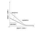
- FIG. 2 is a characteristic diagram showing an example of the relationship between the conduction (energization) current value and the energization time of the electric wire 6, the semiconductor switch 3, and the single operation load 1, respectively.
- the electric wire 6 has a smoke generation characteristic in which the energization time until smoke generation is shortened as the flow (energization) current value increases.
- the semiconductor switch 3 is a commercially available IPD (Intelligent Power Device) and has an overheat shut-off function (characteristic) that shortens the energization time until it is shut off due to overheating as the current value of energization (energization) increases. Have. In this overheat cutoff function, the same current flow cuts off in a time shorter than the energization time of the smoke generation characteristic of the electric wire 6.
- the overheat cutoff function (characteristic) of the semiconductor switch 3 is determined by a temperature sensor built in the semiconductor switch 3.
- the single operation load 1 is a current flow value that causes the electric wire 6 to smoke in the required load operation (the operation of an on-vehicle load that is required under use conditions) within the maximum energization time required for the operation. And the current value smaller than the current value when the semiconductor switch 3 is cut off.
- the single operation load 1 is linked to the load operation switch 4 in the range of the load operation required for the conduction (energization) current value and energization time shown in FIG. Then, it is switched on or off.
- the load operation switch 4 is continuously turned on more than the required load operation of the single operation load 1, or the single operation load 1 is short-circuited and the energization time is a semiconductor with the same current value.
- the semiconductor switch 3 is turned off regardless of the operation to the load operation switch 4.
- the semiconductor switch 3 operates in the same manner as a fuse, and the current to the single operation load 1 is interrupted.
- the semiconductor switch 3 is turned on and the load operation switch The interlocking function with 4 is also restored.
- the load operation switch 4 can also be turned off in conjunction with it.
- FIG. 3 is a block diagram showing a schematic configuration of the vehicle power supply device according to the second embodiment of the present invention.
- a semiconductor switch 7 and a load operation switch 4 are interposed in series in the middle of the electric wire 9.
- a signal indicating an operation to the load operation switch 4 is given to the control unit 8, and the control unit 8 gives a signal based on the given signal to the drive circuit 2 of the semiconductor switch 7 and interlocks with the load operation switch 4. Then, the semiconductor switch 7 is switched on or off.
- FIG. 4 is a characteristic diagram showing an example of the relationship between the conduction (energization) current value and the energization time of the electric wire 9, the semiconductor switch 7, and the single operation load 1, respectively.
- the electric wire 9 has a smoke generation characteristic in which the energization time until smoke generation is shortened as the flow (energization) current value increases.
- the semiconductor switch 7 is a commercially available IPD, and has an overheat cutoff function (characteristic) that shortens the energization time until it is shut down due to overheating as the current value of conduction (energization) increases.
- the same current flow cuts off in a time shorter than the energization time of the smoke generation characteristic of the electric wire 9, but in the range of the energization time longer than the energization time TA (predetermined time), Is reversed to cut off with an energization time longer than the energization time of this smoke generation characteristic.
- the overheat cutoff function (characteristic) of the semiconductor switch 7 is determined by a temperature sensor built in the semiconductor switch 7.
- the single operation load 1 is a current flow value that causes the wire 9 to smoke in the required load operation (the operation of an on-vehicle load that is required under use conditions) within the maximum energization time that is required for operation. And the current value smaller than the current value when the semiconductor switch 7 is cut off.
- the maximum energization time required for the operation of the single operation load 1 is set shorter than the energization time TA.
- the other configuration of the vehicle power supply device is the same as that of the first embodiment described above, and a description thereof will be omitted.
- the semiconductor switch 7 is interlocked with the load operation switch 4 within the range of the necessary load operation of the continuity (energization) current value and energization time shown in FIG. Are switched on or off.
- the semiconductor switch 7 is switched to the load operation switch 4. Turned off regardless of the operation.
- the semiconductor switch 7 operates in the same manner as the fuse, and the current to the single operation load 1 is interrupted.
- the semiconductor switch 7 returns to ON and the load operation switch 4 is also restored, but when short-circuited, the semiconductor switch 7 is repeatedly turned off.
- FIG. 5 is a flowchart showing the operation of the control unit 8 executed in parallel with the above-described operation.
- the control unit 8 turns on the semiconductor switch 7 (S3) and measures the energization time TA. Start (S5).
- the control unit 8 determines whether or not the measured energization time T has reached the energization time TA (S7). If the energization time T has not reached the energization time TA, the load operation switch 4 is turned off. It is determined whether or not the operation is performed so as to turn off the single operation load 1 (S11). If it is not operated to turn off the single operation load 1 (S11), the control unit 8 continues to count the energization time TA, and determines whether the measured energization time T has reached the energization time TA. (S7).
- control unit 8 If the control unit 8 is operated so as to turn off the single operation load 1 (S11), the control unit 8 turns off the semiconductor switch 7 through the drive circuit 2 (S9), and the load operation so as to turn on the single operation load 1 Wait until the switch 4 is operated (S1).
- the control unit 8 turns off the semiconductor switch 7 through the drive circuit 2 (S9), and turns on the single operation load 1 so as to turn on the load operation switch. Wait until 4 is operated (S1).
- the semiconductor switch 7 is switched to the load operation switch. Turned off regardless of the operation to 4. As a result, the semiconductor switch 7 operates in the same manner as the fuse, and the current to the single operation load 1 is interrupted.
- the load operation switch 4 can also be turned off in conjunction with it. Thereby, when the semiconductor switch 7 is automatically turned on, it is possible to avoid a situation in which the single operation load 1 operates against the user's will.
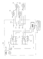
- FIG. 6 is a block diagram showing a schematic configuration of the third embodiment of the vehicle power supply device according to the present invention.
- This vehicle power supply device includes a power supply device 5 such as an in-vehicle battery and an in-vehicle generator, and four door lock motors 15 to 18 which are single-operation loads that operate only for a short period of time, and include an electric wire 19 and a branch line. 20 to 23 are connected.
- the semiconductor switch 10 is interposed in the middle of the electric wire 19, and the load-side terminal of the semiconductor switch 10 is connected to one of the terminals of the door lock relay 11 and the door unlock relay 12.
- the other terminals of the door locking relay 11 and the door unlocking relay 12 are connected to each other by branch lines 20 to 23, and door lock motors 15 to 18 are interposed in the middle of the branch lines 20 to 23, respectively.
- the door lock motor 15 is for the front right (FR) door
- the door lock motor 16 is for the front left (FL) door
- the door lock motor 17 is for the rear right (RR) door
- the door lock motor 18 is the rear left (RL) door. It is for.
- Each of the door locking relay 11 and the door unlocking relay 12 has a grounding terminal.
- the control unit 13 Upon receiving an operation signal from a door lock switch 14 provided on the driver's seat side door, the control unit 13 Each other terminal of the relay 12 is switched and connected to one terminal or a ground terminal. When the control unit 13 connects the other terminals of the relay 11 and the relay 12 to the respective ground terminals, the door lock motors 15 to 18 are disconnected from the power supply device 5.
- the semiconductor switch 10, the relay 11, the door lock motors 15 to 18 group, and the relay 12 are connected. Are connected in series in this order, and the door lock motors 15 to 18 each operate to lock the door.
- the control unit 13 connects the other terminal of the relay 11 to the ground terminal and the other terminal of the relay 12 to one terminal, the semiconductor switch 10, the relay 12, the door lock motors 15 to 18 group, and the relay 11 Are connected in series in this order, and the door lock motors 15 to 18 operate to unlock the doors.
- the electric wire 19 has the same smoke generation characteristic as the electric wire 6 shown in FIG.
- the semiconductor switch 10 is a commercially available IPD and has an overheat cutoff function (characteristic) similar to that of the semiconductor switch 3 shown in FIG.
- the overheat cutoff function of the semiconductor switch 10 cuts off in a time shorter than the energization time of the smoke generation characteristic of the electric wire 19 at the same current flow.
- the overheat cutoff function (characteristic) of the semiconductor switch 10 is determined by a temperature sensor built in the semiconductor switch 10.
- the door lock motors 15 to 18 are supplied with electric power through the respective branch lines 20 to 23, but operate simultaneously, and thus can be regarded as one load. Therefore, by setting the electric wire 19 and the branch lines 20 to 23 to have the same rating and smoke generation characteristics, the door lock motors 15 to 18 are regarded as a single operation load 1 and the same operation as in the first embodiment is performed. It is possible to obtain For the same reason, it is possible to obtain the same operation as in the second embodiment.
- the reason why the electric wire 19 and the branch lines 20 to 23 have the same rating and smoke generation characteristics is that, for example, if any of the door lock motors 15 to 18 is short-circuited, the branch line 20 to 23 This is because the electric wire 19 approaches the smoke generation state first and the semiconductor switch 10 needs to be turned off.
- the present invention can be applied to a vehicle power supply device capable of reducing the diameter of a power supply wire to an in-vehicle load that operates only for a short period of time.
Landscapes
- Engineering & Computer Science (AREA)
- Life Sciences & Earth Sciences (AREA)
- Sustainable Development (AREA)
- Sustainable Energy (AREA)
- Power Engineering (AREA)
- Transportation (AREA)
- Mechanical Engineering (AREA)
- Charge And Discharge Circuits For Batteries Or The Like (AREA)
- Secondary Cells (AREA)
- Emergency Protection Circuit Devices (AREA)
Abstract
単発的に短期間のみ作動する車載負荷への電源供給電線を細径化することができる車両用電源装置を提供する。 車載負荷1及び電源装置5間を接続する電線6と、電線6に介装された操作スイッチ4とを備え、電線6は、通流電流値に応じた通電時間で発煙する発煙特性を有する車両用電源装置。通流電流値に応じた通電時間で遮断する過熱遮断機能を有し、操作スイッチ4に直列に接続され、操作スイッチ4に連動するスイッチ3を備え、スイッチ3の過熱遮断機能は、同一通流電流値では電線6の発煙特性の通電時間より短い時間で遮断する構成である。
Description
本発明は、車載負荷及び電源装置間を接続する電線と、電線に介装された操作スイッチとを備える車両用電源装置に関するものである。
車両には、ホーン及びドアロックモータ等、単発的に短期間のみ作動する負荷が搭載されている。これらの負荷への電源供給回路では、他の連続的に作動する負荷への電源供給回路と同様に、ヒューズを使用して電線を保護しており、これらの電線サイズは、ヒューズの容量に応じて決定されている。
特許文献1には、負荷への通電電流が所定時間毎に検出され、電線の上昇温度が、検出された通電電流を用いて、電線の放熱及び発熱に係る関係式によってマイクロコンピュータ等により算出される電線保護方法及び電線保護装置が開示されている。算出された上昇温度が基準温度に加算されて電線の温度が推定され、推定電線温度が所定の上限温度未満の場合は、上昇温度の算出が繰り返され、推定電線温度が所定の上限電線温度以上となった場合、電源から負荷への電力供給を停止し、電線が保護される。
特開2009-130944号公報
上述した単発的に短期間のみ作動する負荷への電源供給回路では、ヒューズ容量は、単発的に短期間のみ作動する際に流れる電流が、連続的に継続して流れても遮断しないように定められている。その為、実際の負荷の使用条件では、連続的に使用する必要が無いような場合、電線としては必要以上に太くされて過剰仕様となっているという問題がある。
本発明は、上述したような事情に鑑みてなされたものであり、単発的に短期間のみ作動する車載負荷への電源供給電線を細径化することができる車両用電源装置を提供することを目的とする。
第1発明に係る車両用電源装置は、車載負荷及び電源装置間を接続する電線と、該電線に介装された操作スイッチとを備え、前記電線は、通流電流値に応じた通電時間で発煙する発煙特性を有する車両用電源装置において、通流電流値に応じた通電時間で遮断する過熱遮断機能を有し、前記操作スイッチに直列に接続され、該操作スイッチに連動するスイッチを備え、前記過熱遮断機能は、同一通流電流値では前記発煙特性の通電時間より短い時間で遮断することを特徴とする。
この車両用電源装置では、電線が車載負荷及び電源装置間を接続し、操作スイッチが電線に介装されており、電線は、通流電流値に応じた通電時間で発煙する発煙特性を有している。通流電流値に応じた通電時間で遮断する過熱遮断機能を有するスイッチが、操作スイッチに直列に接続され、操作スイッチに連動する。過熱遮断機能は、同一通流電流値では発煙特性の通電時間より短い時間で遮断する。
第2発明に係る車両用電源装置は、車載負荷及び電源装置間を接続する電線と、該電線に介装された操作スイッチとを備え、前記電線は、通流電流値に応じた通電時間で発煙する発煙特性を有する車両用電源装置において、通流電流値に応じた通電時間で遮断する過熱遮断機能を有し、前記操作スイッチに直列に接続され、該操作スイッチに連動するスイッチと、該スイッチが連続してオンである時間を計時する手段と、該手段が所定時間を計時したか否かを判定する手段と、該手段が所定時間を計時したと判定したときに、前記スイッチをオフにする手段とを備え、前記過熱遮断機能は、前記所定時間より短い通電時間の範囲で、同一通流電流値では前記発煙特性の通電時間より短い時間で遮断することを特徴とする。
この車両用電源装置では、電線が車載負荷及び電源装置間を接続し、操作スイッチが電線に介装され、電線は、通流電流値に応じた通電時間で発煙する発煙特性を有している。通流電流値に応じた通電時間で遮断する過熱遮断機能を有するスイッチが、操作スイッチに直列に接続され、操作スイッチに連動する。計時する手段が、スイッチが連続してオンである時間を計時し、判定する手段が、計時する手段が所定時間を計時したか否かを判定する。判定する手段が所定時間を計時したと判定したときに、スイッチをオフにする。過熱遮断機能では、所定時間より短い通電時間の範囲で、同一通流電流値では発煙特性の通電時間より短い時間で遮断する。
本発明に係る車両用電源装置によれば、単発的に短期間のみ作動する車載負荷への電源供給電線を細径化することができ、その車載負荷の使用条件上必要とされない動作が行われた場合は、電源供給を遮断することができ、省電力化することができる。また、先行技術のように、マイクロコンピュータ等を用いた複雑な計算を必要とせず、低コストで実現することができる。
1 単発動作負荷(車載負荷)
2 駆動回路
3,7,10 半導体スイッチ(スイッチ)
4 負荷操作スイッチ(操作スイッチ)
5 電源装置
6,9,19 電線
8 制御部
11 (ドアロック用)リレー(操作スイッチ)
12 (ドアアンロック用)リレー(操作スイッチ)
13 制御部
14 ドアロックスイッチ
15~18 ドアロックモータ(車載負荷)
20~23 分岐線
2 駆動回路
3,7,10 半導体スイッチ(スイッチ)
4 負荷操作スイッチ(操作スイッチ)
5 電源装置
6,9,19 電線
8 制御部
11 (ドアロック用)リレー(操作スイッチ)
12 (ドアアンロック用)リレー(操作スイッチ)
13 制御部
14 ドアロックスイッチ
15~18 ドアロックモータ(車載負荷)
20~23 分岐線
以下に、本発明をその実施の形態を示す図面に基づき説明する。
(実施の形態1)
図1は、本発明に係る車両用電源装置の実施の形態1の概略構成を示すブロック図である。
この車両用電源装置は、車載バッテリ、車載発電機等の電源装置5と、例えばホーン、ドアロック等の単発的に短期間のみ作動する単発動作負荷1とが、電線6により接続されている。電線6の中途には半導体スイッチ3及び負荷操作スイッチ4が直列に介装されている。
負荷操作スイッチ4への操作を示す信号が、半導体スイッチ3の駆動回路2に与えられ、駆動回路2は、負荷操作スイッチ4に連動して、半導体スイッチ3をオン又はオフに切替える。
(実施の形態1)
図1は、本発明に係る車両用電源装置の実施の形態1の概略構成を示すブロック図である。
この車両用電源装置は、車載バッテリ、車載発電機等の電源装置5と、例えばホーン、ドアロック等の単発的に短期間のみ作動する単発動作負荷1とが、電線6により接続されている。電線6の中途には半導体スイッチ3及び負荷操作スイッチ4が直列に介装されている。
負荷操作スイッチ4への操作を示す信号が、半導体スイッチ3の駆動回路2に与えられ、駆動回路2は、負荷操作スイッチ4に連動して、半導体スイッチ3をオン又はオフに切替える。
図2は、電線6、半導体スイッチ3及び単発動作負荷1がそれぞれ有する通流(通電)電流値と通電時間との関係の例を示す特性図である。
電線6は、通流(通電)電流値が大きくなるに応じて、発煙する迄の通電時間が短くなる発煙特性を有している。
半導体スイッチ3は、市販されているIPD(Intelligent Power Device)であり、通流(通電)電流値が大きくなるに応じて、過熱により遮断する迄の通電時間が短くなる過熱遮断機能(特性)を有している。この過熱遮断機能では、同一の通流電流では、電線6の発煙特性の通電時間より短い時間で遮断する。
電線6は、通流(通電)電流値が大きくなるに応じて、発煙する迄の通電時間が短くなる発煙特性を有している。
半導体スイッチ3は、市販されているIPD(Intelligent Power Device)であり、通流(通電)電流値が大きくなるに応じて、過熱により遮断する迄の通電時間が短くなる過熱遮断機能(特性)を有している。この過熱遮断機能では、同一の通流電流では、電線6の発煙特性の通電時間より短い時間で遮断する。
半導体スイッチ3が有する過熱遮断機能(特性)は、半導体スイッチ3が内蔵する温度センサにより定められる。
単発動作負荷1は、必要とされる負荷動作(使用条件上必要とされる車載負荷の動作)では、動作が必要とされる最長限度の通電時間以下で、電線6の発煙する通流電流値、及び半導体スイッチ3の遮断時の通流電流値より小さい電流値で作動する。
単発動作負荷1は、必要とされる負荷動作(使用条件上必要とされる車載負荷の動作)では、動作が必要とされる最長限度の通電時間以下で、電線6の発煙する通流電流値、及び半導体スイッチ3の遮断時の通流電流値より小さい電流値で作動する。
このような構成の車両用電源装置では、単発動作負荷1は、図2に示す通流(通電)電流値及び通電時間の必要負荷動作の範囲では、半導体スイッチ3は、負荷操作スイッチ4に連動して、オン又はオフに切替えられる。
負荷操作スイッチ4が、単発動作負荷1の必要とされる負荷動作以上に継続してオンに操作され、又は単発動作負荷1が短絡して、通電時間が、同一の通流電流値での半導体スイッチ3の過熱遮断特性の通電時間に達したとき、半導体スイッチ3は、負荷操作スイッチ4への操作に関係なくオフにされる。
負荷操作スイッチ4が、単発動作負荷1の必要とされる負荷動作以上に継続してオンに操作され、又は単発動作負荷1が短絡して、通電時間が、同一の通流電流値での半導体スイッチ3の過熱遮断特性の通電時間に達したとき、半導体スイッチ3は、負荷操作スイッチ4への操作に関係なくオフにされる。
これにより、半導体スイッチ3は、ヒューズと同様に作動し、単発動作負荷1への電流が遮断される。
単発動作負荷1への電流が遮断された状態で、半導体スイッチ3の温度が所定温度迄低下したとき、又は定められた時間が経過したとき、半導体スイッチ3は、オンに復帰し、負荷操作スイッチ4との連動機能も復帰する。
尚、通電時間が過熱遮断特性の通電時間に達して、半導体スイッチ3がオフになるときに、負荷操作スイッチ4も連動してオフになるようにすることも可能である。これにより、半導体スイッチ3が、自動的にオンに復帰した際に、単発動作負荷1が、ユーザの意志に反して作動するような事態を避けることができる。
単発動作負荷1への電流が遮断された状態で、半導体スイッチ3の温度が所定温度迄低下したとき、又は定められた時間が経過したとき、半導体スイッチ3は、オンに復帰し、負荷操作スイッチ4との連動機能も復帰する。
尚、通電時間が過熱遮断特性の通電時間に達して、半導体スイッチ3がオフになるときに、負荷操作スイッチ4も連動してオフになるようにすることも可能である。これにより、半導体スイッチ3が、自動的にオンに復帰した際に、単発動作負荷1が、ユーザの意志に反して作動するような事態を避けることができる。
(実施の形態2)
図3は、本発明に係る車両用電源装置の実施の形態2の概略構成を示すブロック図である。
この車両用電源装置は、電線9の中途には半導体スイッチ7及び負荷操作スイッチ4が直列に介装されている。
負荷操作スイッチ4への操作を示す信号が、制御部8に与えられ、制御部8は、与えられた信号に基づく信号を、半導体スイッチ7の駆動回路2に与えて、負荷操作スイッチ4に連動して、半導体スイッチ7をオン又はオフに切替える。
図3は、本発明に係る車両用電源装置の実施の形態2の概略構成を示すブロック図である。
この車両用電源装置は、電線9の中途には半導体スイッチ7及び負荷操作スイッチ4が直列に介装されている。
負荷操作スイッチ4への操作を示す信号が、制御部8に与えられ、制御部8は、与えられた信号に基づく信号を、半導体スイッチ7の駆動回路2に与えて、負荷操作スイッチ4に連動して、半導体スイッチ7をオン又はオフに切替える。
図4は、電線9、半導体スイッチ7及び単発動作負荷1がそれぞれ有する通流(通電)電流値と通電時間との関係の例を示す特性図である。
電線9は、通流(通電)電流値が大きくなるに応じて、発煙する迄の通電時間が短くなる発煙特性を有している。
半導体スイッチ7は、市販されているIPDであり、通流(通電)電流値が大きくなるに応じて、過熱により遮断する迄の通電時間が短くなる過熱遮断機能(特性)を有している。この過熱遮断機能では、同一の通流電流では、電線9の発煙特性の通電時間より短い時間で遮断するが、通電時間TA(所定時間)より長い通電時間の範囲では、電線9の発煙特性とは逆転して、この発煙特性の通電時間より長い通電時間で遮断するようになっている。
電線9は、通流(通電)電流値が大きくなるに応じて、発煙する迄の通電時間が短くなる発煙特性を有している。
半導体スイッチ7は、市販されているIPDであり、通流(通電)電流値が大きくなるに応じて、過熱により遮断する迄の通電時間が短くなる過熱遮断機能(特性)を有している。この過熱遮断機能では、同一の通流電流では、電線9の発煙特性の通電時間より短い時間で遮断するが、通電時間TA(所定時間)より長い通電時間の範囲では、電線9の発煙特性とは逆転して、この発煙特性の通電時間より長い通電時間で遮断するようになっている。
半導体スイッチ7が有する過熱遮断機能(特性)は、半導体スイッチ7が内蔵する温度センサにより定められる。
単発動作負荷1は、必要とされる負荷動作(使用条件上必要とされる車載負荷の動作)では、動作が必要とされる最長限度の通電時間以下で、電線9の発煙する通流電流値、及び半導体スイッチ7の遮断時の通流電流値より小さい電流値で作動する。単発動作負荷1の動作が必要とされる最長限度の通電時間は、通電時間TAより短く設定してある。この車両用電源装置のその他の構成は、上述した実施の形態1の構成と同様であるので、説明を省略する。
単発動作負荷1は、必要とされる負荷動作(使用条件上必要とされる車載負荷の動作)では、動作が必要とされる最長限度の通電時間以下で、電線9の発煙する通流電流値、及び半導体スイッチ7の遮断時の通流電流値より小さい電流値で作動する。単発動作負荷1の動作が必要とされる最長限度の通電時間は、通電時間TAより短く設定してある。この車両用電源装置のその他の構成は、上述した実施の形態1の構成と同様であるので、説明を省略する。
このような構成の車両用電源装置では、単発動作負荷1の図4に示す通流(通電)電流値及び通電時間の必要負荷動作の範囲で、半導体スイッチ7は、負荷操作スイッチ4に連動して、オン又はオフに切替えられる。
単発動作負荷1が短絡して通電電流が急増し、通電時間が、同一の通流電流値での半導体スイッチ7の過熱遮断特性の通電時間に達したとき、半導体スイッチ7は、負荷操作スイッチ4への操作に関係なくオフにされる。
単発動作負荷1が短絡して通電電流が急増し、通電時間が、同一の通流電流値での半導体スイッチ7の過熱遮断特性の通電時間に達したとき、半導体スイッチ7は、負荷操作スイッチ4への操作に関係なくオフにされる。
これにより、半導体スイッチ7は、ヒューズと同様に作動し、単発動作負荷1への電流が遮断される。
単発動作負荷1への電流が遮断された状態で、半導体スイッチ7の温度が所定温度迄低下したとき、又は定められた時間が経過したとき、半導体スイッチ7は、オンに復帰し、負荷操作スイッチ4との連動機能も復帰するが、短絡している場合は、半導体スイッチ7は繰返しオフにされる。
単発動作負荷1への電流が遮断された状態で、半導体スイッチ7の温度が所定温度迄低下したとき、又は定められた時間が経過したとき、半導体スイッチ7は、オンに復帰し、負荷操作スイッチ4との連動機能も復帰するが、短絡している場合は、半導体スイッチ7は繰返しオフにされる。
図5は、上述した動作と並行して実行される制御部8の動作を示すフローチャートである。
以下に、制御部8の動作を、図5のフローチャートを参照しながら説明する。
制御部8は、負荷操作スイッチ4がオンに操作され、単発動作負荷1をオンにするように操作されると(S1)、半導体スイッチ7をオンにして(S3)、通電時間TAの計時を開始する(S5)。
以下に、制御部8の動作を、図5のフローチャートを参照しながら説明する。
制御部8は、負荷操作スイッチ4がオンに操作され、単発動作負荷1をオンにするように操作されると(S1)、半導体スイッチ7をオンにして(S3)、通電時間TAの計時を開始する(S5)。
次に、制御部8は、計時した通電時間Tが通電時間TAに達したか否かを判定し(S7)、通電時間Tが通電時間TAに達していなければ、負荷操作スイッチ4がオフに操作され、単発動作負荷1をオフにするように操作されていないかを判定する(S11)。
制御部8は、単発動作負荷1をオフにするように操作されていなければ(S11)、通電時間TAの計時を継続し、計時した通電時間Tが通電時間TAに達したか否かを判定する(S7)。制御部8は、単発動作負荷1をオフにするように操作されていれば(S11)、駆動回路2を通じて半導体スイッチ7をオフにし(S9)、単発動作負荷1をオンにするように負荷操作スイッチ4が操作される迄待機する(S1)。
制御部8は、単発動作負荷1をオフにするように操作されていなければ(S11)、通電時間TAの計時を継続し、計時した通電時間Tが通電時間TAに達したか否かを判定する(S7)。制御部8は、単発動作負荷1をオフにするように操作されていれば(S11)、駆動回路2を通じて半導体スイッチ7をオフにし(S9)、単発動作負荷1をオンにするように負荷操作スイッチ4が操作される迄待機する(S1)。
制御部8は、計時した通電時間Tが通電時間TAに達していれば(S7)、駆動回路2を通じて半導体スイッチ7をオフにし(S9)、単発動作負荷1をオンにするように負荷操作スイッチ4が操作される迄待機する(S1)。
以上より、負荷操作スイッチ4が、単発動作負荷1の必要とされる負荷動作以上に継続してオンに操作され、通電時間が所定時間TAに達したときは、半導体スイッチ7が、負荷操作スイッチ4への操作に関係なくオフにされる。
これにより、半導体スイッチ7は、ヒューズと同様に作動し、単発動作負荷1への電流が遮断される。
以上より、負荷操作スイッチ4が、単発動作負荷1の必要とされる負荷動作以上に継続してオンに操作され、通電時間が所定時間TAに達したときは、半導体スイッチ7が、負荷操作スイッチ4への操作に関係なくオフにされる。
これにより、半導体スイッチ7は、ヒューズと同様に作動し、単発動作負荷1への電流が遮断される。
尚、通電時間が所定時間TAに達して、半導体スイッチ7がオフになるときに、負荷操作スイッチ4も連動してオフになるようにすることも可能である。これにより、半導体スイッチ7が、自動的にオンに復帰した際に、単発動作負荷1が、ユーザの意志に反して作動するような事態を避けることができる。
(実施の形態3)
図6は、本発明に係る車両用電源装置の実施の形態3の概略構成を示すブロック図である。
この車両用電源装置は、車載バッテリ、車載発電機等の電源装置5と、単発的に短期間のみ作動する単発動作負荷である4台のドアロックモータ15~18とが、電線19及び分岐線20~23により接続されている。電線19の中途には半導体スイッチ10が介装され、半導体スイッチ10の負荷側の端子は、ドアロック用リレー11及びドアアンロック用リレー12の各一方の端子に接続されている。
図6は、本発明に係る車両用電源装置の実施の形態3の概略構成を示すブロック図である。
この車両用電源装置は、車載バッテリ、車載発電機等の電源装置5と、単発的に短期間のみ作動する単発動作負荷である4台のドアロックモータ15~18とが、電線19及び分岐線20~23により接続されている。電線19の中途には半導体スイッチ10が介装され、半導体スイッチ10の負荷側の端子は、ドアロック用リレー11及びドアアンロック用リレー12の各一方の端子に接続されている。
ドアロック用リレー11及びドアアンロック用リレー12の各他方の端子は、分岐線20~23により互いに接続され、分岐線20~23の各中途には、ドアロックモータ15~18がそれぞれ介装されている。ドアロックモータ15は前方右側(FR)ドア用、ドアロックモータ16は前方左側(FL)ドア用、ドアロックモータ17は後方右側(RR)ドア用、ドアロックモータ18は後方左側(RL)ドア用である。
ドアロック用リレー11及びドアアンロック用リレー12は、それぞれ接地端子を有しており、運転席側ドアに設けられたドアロックスイッチ14の操作信号を受けて、制御部13が、リレー11及びリレー12の各他方の端子を、それぞれの一方の端子又は接地端子に切替え接続する。
制御部13が、リレー11及びリレー12の各他方の端子を、それぞれの接地端子に接続した場合、ドアロックモータ15~18は電源装置5から遮断される。
制御部13が、リレー11及びリレー12の各他方の端子を、それぞれの接地端子に接続した場合、ドアロックモータ15~18は電源装置5から遮断される。
制御部13が、リレー11の他方の端子を一方の端子に接続し、リレー12の他方の端子を接地端子に接続した場合、半導体スイッチ10、リレー11、ドアロックモータ15~18群及びリレー12が、この順序で直列に接続され、ドアロックモータ15~18は、それぞれドアをロックするように作動する。
制御部13が、リレー11の他方の端子を接地端子に接続し、リレー12の他方の端子を一方の端子に接続した場合、半導体スイッチ10、リレー12、ドアロックモータ15~18群及びリレー11が、この順序で直列に接続され、ドアロックモータ15~18は、それぞれドアをアンロックするように作動する。
制御部13が、リレー11の他方の端子を接地端子に接続し、リレー12の他方の端子を一方の端子に接続した場合、半導体スイッチ10、リレー12、ドアロックモータ15~18群及びリレー11が、この順序で直列に接続され、ドアロックモータ15~18は、それぞれドアをアンロックするように作動する。
電線19は、電線6の図2に示すと同様の発煙特性を有している。
半導体スイッチ10は、市販されているIPDであり、半導体スイッチ3の図2に示すと同様の過熱遮断機能(特性)を有している。半導体スイッチ10の過熱遮断機能は、同一の通流電流では、電線19の発煙特性の通電時間より短い時間で遮断する。
半導体スイッチ10が有する過熱遮断機能(特性)は、半導体スイッチ10が内蔵する温度センサにより定められる。
半導体スイッチ10は、市販されているIPDであり、半導体スイッチ3の図2に示すと同様の過熱遮断機能(特性)を有している。半導体スイッチ10の過熱遮断機能は、同一の通流電流では、電線19の発煙特性の通電時間より短い時間で遮断する。
半導体スイッチ10が有する過熱遮断機能(特性)は、半導体スイッチ10が内蔵する温度センサにより定められる。
ドアロックモータ15~18は、それぞれの分岐線20~23により電力を供給されるが、同時的に作動するので、1つの負荷と見做すことができる。従って、電線19と各分岐線20~23とを同一の定格及び発煙特性としておくことにより、ドアロックモータ15~18群を単発動作負荷1と見做して、実施の形態1と同様の動作を得ることが可能である。また、同様の理由により、実施の形態2と同様の動作を得ることも可能である。
ここで、電線19と各分岐線20~23とを同一の定格及び発煙特性としておくのは、例えば、ドアロックモータ15~18の何れかが短絡した場合、分岐線20~23の何れかよりも先に、電線19が発煙状態に近付き、半導体スイッチ10をオフにする必要があるからである。
ここで、電線19と各分岐線20~23とを同一の定格及び発煙特性としておくのは、例えば、ドアロックモータ15~18の何れかが短絡した場合、分岐線20~23の何れかよりも先に、電線19が発煙状態に近付き、半導体スイッチ10をオフにする必要があるからである。
本発明は、単発的に短期間のみ作動する車載負荷への電源供給電線を細径化することができる車両用電源装置に適用できる。
Claims (2)
- 車載負荷及び電源装置間を接続する電線と、該電線に介装された操作スイッチとを備え、前記電線は、通流電流値に応じた通電時間で発煙する発煙特性を有する車両用電源装置において、
通流電流値に応じた通電時間で遮断する過熱遮断機能を有し、前記操作スイッチに直列に接続され、該操作スイッチに連動するスイッチを備え、前記過熱遮断機能は、同一通流電流値では前記発煙特性の通電時間より短い時間で遮断することを特徴とする車両用電源装置。 - 車載負荷及び電源装置間を接続する電線と、該電線に介装された操作スイッチとを備え、前記電線は、通流電流値に応じた通電時間で発煙する発煙特性を有する車両用電源装置において、
通流電流値に応じた通電時間で遮断する過熱遮断機能を有し、前記操作スイッチに直列に接続され、該操作スイッチに連動するスイッチと、該スイッチが連続してオンである時間を計時する手段と、該手段が所定時間を計時したか否かを判定する手段と、該手段が所定時間を計時したと判定したときに、前記スイッチをオフにする手段とを備え、前記過熱遮断機能は、前記所定時間より短い通電時間の範囲で、同一通流電流値では前記発煙特性の通電時間より短い時間で遮断することを特徴とする車両用電源装置。
Applications Claiming Priority (2)
| Application Number | Priority Date | Filing Date | Title |
|---|---|---|---|
| JP2011-120770 | 2011-05-30 | ||
| JP2011120770A JP2012245937A (ja) | 2011-05-30 | 2011-05-30 | 車両用電源装置 |
Publications (1)
| Publication Number | Publication Date |
|---|---|
| WO2012165364A1 true WO2012165364A1 (ja) | 2012-12-06 |
Family
ID=47259220
Family Applications (1)
| Application Number | Title | Priority Date | Filing Date |
|---|---|---|---|
| PCT/JP2012/063591 Ceased WO2012165364A1 (ja) | 2011-05-30 | 2012-05-28 | 車両用電源装置 |
Country Status (2)
| Country | Link |
|---|---|
| JP (1) | JP2012245937A (ja) |
| WO (1) | WO2012165364A1 (ja) |
Cited By (2)
| Publication number | Priority date | Publication date | Assignee | Title |
|---|---|---|---|---|
| JP2015217837A (ja) * | 2014-05-19 | 2015-12-07 | 株式会社オートネットワーク技術研究所 | 自動車用電源装置 |
| CN116872738A (zh) * | 2023-08-16 | 2023-10-13 | 东风汽车有限公司东风日产乘用车公司 | 热失效防护方法、装置、设备及存储介质 |
Families Citing this family (1)
| Publication number | Priority date | Publication date | Assignee | Title |
|---|---|---|---|---|
| WO2023242989A1 (ja) * | 2022-06-15 | 2023-12-21 | 株式会社オートネットワーク技術研究所 | 遮断制御装置 |
Citations (2)
| Publication number | Priority date | Publication date | Assignee | Title |
|---|---|---|---|---|
| JPH11240395A (ja) * | 1998-02-24 | 1999-09-07 | Yazaki Corp | 車両用電気回路保護装置 |
| JP2009120138A (ja) * | 2007-11-19 | 2009-06-04 | Nissan Motor Co Ltd | 電源遮断制御システムおよび電源遮断制御方法 |
-
2011
- 2011-05-30 JP JP2011120770A patent/JP2012245937A/ja not_active Withdrawn
-
2012
- 2012-05-28 WO PCT/JP2012/063591 patent/WO2012165364A1/ja not_active Ceased
Patent Citations (2)
| Publication number | Priority date | Publication date | Assignee | Title |
|---|---|---|---|---|
| JPH11240395A (ja) * | 1998-02-24 | 1999-09-07 | Yazaki Corp | 車両用電気回路保護装置 |
| JP2009120138A (ja) * | 2007-11-19 | 2009-06-04 | Nissan Motor Co Ltd | 電源遮断制御システムおよび電源遮断制御方法 |
Cited By (2)
| Publication number | Priority date | Publication date | Assignee | Title |
|---|---|---|---|---|
| JP2015217837A (ja) * | 2014-05-19 | 2015-12-07 | 株式会社オートネットワーク技術研究所 | 自動車用電源装置 |
| CN116872738A (zh) * | 2023-08-16 | 2023-10-13 | 东风汽车有限公司东风日产乘用车公司 | 热失效防护方法、装置、设备及存储介质 |
Also Published As
| Publication number | Publication date |
|---|---|
| JP2012245937A (ja) | 2012-12-13 |
Similar Documents
| Publication | Publication Date | Title |
|---|---|---|
| JP7004022B2 (ja) | 制御装置及び車両 | |
| US10703206B2 (en) | Device for monitoring a high-voltage on-board power supply system of an electrically operated vehicle for the occurrence of overloading | |
| JP6394535B2 (ja) | 電線保護装置 | |
| JP2008500223A (ja) | 電子式バッテリ安全スイッチ | |
| JP2012125072A (ja) | 車両用電力分配装置 | |
| CN111016821A (zh) | 具有电力插座的混合动力车辆 | |
| JP6503636B2 (ja) | モータ制御装置 | |
| JP2011509068A (ja) | インターロックスイッチを用いたプレチャージ抵抗保護回路装置 | |
| CN108886266A (zh) | 继电器装置及车载系统 | |
| WO2018163736A1 (ja) | 車載用電池の保護回路 | |
| US10300792B2 (en) | Device for a motor vehicle | |
| JP2018002080A (ja) | 車載システム | |
| JPH09284902A (ja) | 電気自動車の短絡検出回路 | |
| JP2019047569A (ja) | 車両用配電ボックス | |
| WO2012165364A1 (ja) | 車両用電源装置 | |
| JP5169629B2 (ja) | リレー制御装置 | |
| JP2004159439A (ja) | 電源遮断装置 | |
| JP2005312156A (ja) | 電源制御装置およびそれを備えたモータ駆動装置 | |
| JP2003503998A (ja) | バッテリーシステム | |
| JP2005245049A (ja) | 電源回路の制御装置 | |
| CN111180808B (zh) | 用于在机动车的车载电网上使用的电池组系统 | |
| CN118618234B (zh) | 一种用于汽车的低压供电系统 | |
| CN103568846B (zh) | 电动汽车高压保护系统及方法 | |
| JP6820177B2 (ja) | 電動車両の制御装置 | |
| JP2009299560A (ja) | 車両用電源装置 |
Legal Events
| Date | Code | Title | Description |
|---|---|---|---|
| 121 | Ep: the epo has been informed by wipo that ep was designated in this application |
Ref document number: 12793455 Country of ref document: EP Kind code of ref document: A1 |
|
| NENP | Non-entry into the national phase |
Ref country code: DE |
|
| 122 | Ep: pct application non-entry in european phase |
Ref document number: 12793455 Country of ref document: EP Kind code of ref document: A1 |