WO2012165343A1 - 基地局及び無線リソースの割り当て方法 - Google Patents
基地局及び無線リソースの割り当て方法 Download PDFInfo
- Publication number
- WO2012165343A1 WO2012165343A1 PCT/JP2012/063520 JP2012063520W WO2012165343A1 WO 2012165343 A1 WO2012165343 A1 WO 2012165343A1 JP 2012063520 W JP2012063520 W JP 2012063520W WO 2012165343 A1 WO2012165343 A1 WO 2012165343A1
- Authority
- WO
- WIPO (PCT)
- Prior art keywords
- communication terminal
- communication
- srs
- downlink
- radio resource
- Prior art date
- Legal status (The legal status is an assumption and is not a legal conclusion. Google has not performed a legal analysis and makes no representation as to the accuracy of the status listed.)
- Ceased
Links
Images










Classifications
-
- H—ELECTRICITY
- H04—ELECTRIC COMMUNICATION TECHNIQUE
- H04W—WIRELESS COMMUNICATION NETWORKS
- H04W72/00—Local resource management
- H04W72/04—Wireless resource allocation
- H04W72/044—Wireless resource allocation based on the type of the allocated resource
-
- H—ELECTRICITY
- H04—ELECTRIC COMMUNICATION TECHNIQUE
- H04L—TRANSMISSION OF DIGITAL INFORMATION, e.g. TELEGRAPHIC COMMUNICATION
- H04L5/00—Arrangements affording multiple use of the transmission path
- H04L5/003—Arrangements for allocating sub-channels of the transmission path
- H04L5/0037—Inter-user or inter-terminal allocation
-
- H—ELECTRICITY
- H04—ELECTRIC COMMUNICATION TECHNIQUE
- H04B—TRANSMISSION
- H04B7/00—Radio transmission systems, i.e. using radiation field
- H04B7/02—Diversity systems; Multi-antenna system, i.e. transmission or reception using multiple antennas
- H04B7/04—Diversity systems; Multi-antenna system, i.e. transmission or reception using multiple antennas using two or more spaced independent antennas
- H04B7/06—Diversity systems; Multi-antenna system, i.e. transmission or reception using multiple antennas using two or more spaced independent antennas at the transmitting station
- H04B7/0613—Diversity systems; Multi-antenna system, i.e. transmission or reception using multiple antennas using two or more spaced independent antennas at the transmitting station using simultaneous transmission
- H04B7/0615—Diversity systems; Multi-antenna system, i.e. transmission or reception using multiple antennas using two or more spaced independent antennas at the transmitting station using simultaneous transmission of weighted versions of same signal
- H04B7/0617—Diversity systems; Multi-antenna system, i.e. transmission or reception using multiple antennas using two or more spaced independent antennas at the transmitting station using simultaneous transmission of weighted versions of same signal for beam forming
-
- H—ELECTRICITY
- H04—ELECTRIC COMMUNICATION TECHNIQUE
- H04B—TRANSMISSION
- H04B7/00—Radio transmission systems, i.e. using radiation field
- H04B7/02—Diversity systems; Multi-antenna system, i.e. transmission or reception using multiple antennas
- H04B7/04—Diversity systems; Multi-antenna system, i.e. transmission or reception using multiple antennas using two or more spaced independent antennas
- H04B7/08—Diversity systems; Multi-antenna system, i.e. transmission or reception using multiple antennas using two or more spaced independent antennas at the receiving station
- H04B7/0837—Diversity systems; Multi-antenna system, i.e. transmission or reception using multiple antennas using two or more spaced independent antennas at the receiving station using pre-detection combining
- H04B7/0842—Weighted combining
-
- H—ELECTRICITY
- H04—ELECTRIC COMMUNICATION TECHNIQUE
- H04W—WIRELESS COMMUNICATION NETWORKS
- H04W72/00—Local resource management
- H04W72/04—Wireless resource allocation
- H04W72/044—Wireless resource allocation based on the type of the allocated resource
- H04W72/0446—Resources in time domain, e.g. slots or frames
-
- H—ELECTRICITY
- H04—ELECTRIC COMMUNICATION TECHNIQUE
- H04W—WIRELESS COMMUNICATION NETWORKS
- H04W72/00—Local resource management
- H04W72/04—Wireless resource allocation
- H04W72/044—Wireless resource allocation based on the type of the allocated resource
- H04W72/0453—Resources in frequency domain, e.g. a carrier in FDMA
Definitions
- the present invention relates to a base station that controls transmission directivity with a plurality of antennas.
- Patent Literature 1 discloses a technology related to LTE (Long Term Term Evolution). LTE is also referred to as “E-UTRA”.
- an adaptive array antenna system that adaptively controls the directivity of a plurality of antennas may be employed.
- the base station is desired to improve its performance.
- the present invention has been made in view of the above points, and provides a technique capable of improving the performance of a base station that communicates with a communication terminal by controlling the transmission directivity of a plurality of antennas. For the purpose.
- a base station is a base station that communicates with a communication terminal, has a plurality of antennas, and performs downlink communication with the communication terminal based on a known signal from the communication terminal.
- a communication unit that controls transmission directivity in the mobile station, and a downlink radio resource used by the communication unit for downlink communication with the communication terminal is allocated to the communication terminal, and the communication terminal is used to transmit a known signal.
- a radio resource allocating unit that allocates uplink radio resources for known signals to be used to the communication terminal, and a first uplink communication period in which the communication terminal transmits a known signal and downlink communication that appears after the uplink communication period are performed.
- a plurality of unit periods including a plurality of downlink communication periods repetitively appear as a plurality of bandwidths that can be set as transmission frequency bandwidths of known signals.
- a bandwidth is defined, and the radio resource allocation unit determines, for each of the plurality of communication terminals with which the communication unit communicates, a transmission frequency bandwidth of a known signal transmitted by the communication terminal, out of the plurality of bandwidths
- a communication terminal configured to set a minimum bandwidth and transmitting a known signal in the first uplink communication period included in the unit period, including a frequency band included in a transmission frequency band of the known signal in a frequency direction; and
- a downlink radio resource including the plurality of downlink communication periods included in the unit period in the time direction is allocated as the used downlink radio resource.
- a radio resource allocation method performs communication with a communication terminal using a plurality of antennas, and performs downlink communication with the communication terminal based on a known signal from the communication terminal.
- a method of assigning radio resources to a communication terminal in a base station that controls transmission directivity in the communication station wherein (a) the used downlink radio resource used by the base station in downlink communication with the communication terminal is assigned to the communication terminal And (b) an uplink communication period in which the communication terminal transmits a known signal, and (b) a step of allocating an uplink radio resource for use known signal used for transmission of the known signal to the communication terminal.
- a plurality of bandwidths having different sizes are determined as bandwidths that can be transmitted, and in the step (b), for each of a plurality of communication terminals with which the base station communicates, a known transmission that the communication terminal transmits A transmission frequency bandwidth of a signal is set to a minimum bandwidth among the plurality of bandwidths, and in the step (a), for a communication terminal that transmits a known signal in the uplink communication period included in the unit period
- a downlink radio resource including the frequency band included in the transmission frequency band of the known signal in the frequency direction and including the plurality of downlink communication periods included in the unit period in the time direction is allocated as the used downlink radio resource.
- the performance of the base station is improved.
- FIG. 1 is a diagram showing a configuration of a communication system 100 according to an embodiment of the present invention.
- the communication system 100 is, for example, LTE that employs a TDD (Time Division Duplexing) scheme as a duplex scheme, and includes a plurality of base stations 1. Each base station 1 communicates with a plurality of communication terminals 2.
- OFDMA Orthogonal Frequency Division Access
- SC-FDMA Single Carrier-Frequency Division Multiple Access
- the OFDMA method is used for transmission from the base station 1 to the communication terminal 2
- the SC-FDMA method is used for transmission from the communication terminal 2 to the base station 1.
- an OFDM OrthogonFrequency Division Multiplexing
- each base station 1 partially overlaps the service area 10 of the surrounding base station 1.
- only four base stations 1 are shown, so there are only two or three neighboring base stations 1 for one base station 1, but in reality one base station 1 For example, there may be six neighboring base stations 1 for the station 1.
- the plurality of base stations 1 are connected to a network (not shown) and can communicate with each other through the network. Further, a server device (not shown) is connected to the network, and each base station 1 can communicate with the server device through the network.
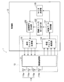
- FIG. 2 is a diagram showing a configuration of each base station 1 according to the embodiment of the present invention.
- the base station 1 can simultaneously communicate with the plurality of communication terminals 2 by individually allocating radio resources specified in two dimensions including a time axis and a frequency axis to each of the plurality of communication terminals 2. It has become.
- the base station 1 has an array antenna as a transmission / reception antenna, and can control the directivity of the array antenna using an adaptive array antenna system.
- the base station 1 includes a wireless processing unit 11 and a control unit 12 that controls the wireless processing unit 11.
- the wireless processing unit 11 includes an array antenna 110 including a plurality of antennas 110a.
- the radio processing unit 11 performs amplification processing, down-conversion, A / D conversion processing, and the like on each of the plurality of reception signals received by the array antenna 110, and generates and outputs a plurality of baseband reception signals. To do.
- the radio processing unit 11 performs D / A conversion processing, up-conversion, amplification processing, and the like on each of the plurality of baseband transmission signals generated by the control unit 12 to transmit a plurality of transmissions in the carrier band. Generate a signal. Then, the wireless processing unit 11 inputs the generated plurality of transmission signals in the carrier band to the plurality of antennas 110a configuring the array antenna 110, respectively. Thereby, a transmission signal is wirelessly transmitted from each antenna 110a.
- the control unit 12 includes a CPU (Central Processing Unit), a DSP (Digital Signal Processor), a memory, and the like.
- the CPU and the DSP execute the program in the memory, whereby the transmission signal generation unit 120, the reception data acquisition unit 121, the radio resource allocation unit 122, the transmission weight processing unit 123, the reception weight processing unit 124, and the MCS.
- a plurality of functional blocks such as the determination unit 125 are formed.
- the MCS determination unit 125 determines an MCS (Modulation Coding Scheme) to be applied to a transmission signal transmitted from the base station 1 to the communication terminal 2.
- MCS indicates a combination of a modulation scheme such as QPSK (Quadrature Phase Shift Keying), 16QAM (Quadrature Amplitude ⁇ Modulation) and the coding rate of the error correction code.
- the MCS determination unit 125 determines the MCS applied to the transmission signal transmitted to the communication terminal 2 as a transmission path characteristic (wireless) in the downlink direction between the base station 1 and the communication terminal 2 in the frequency band of the transmission signal. To be determined based on the characteristics).
- the transmission signal generation unit 120 generates transmission data to be transmitted to the communication terminal 2 to be communicated.
- the transmission data includes control data and user data.
- the transmission signal generation unit 120 generates a baseband transmission signal including the generated transmission data based on the MCS determined by the MCS determination unit 125. This transmission signal is generated by the number of the plurality of antennas 110a constituting the array antenna 110.
- the transmission weight processing unit 123 sets a plurality of transmission weights for controlling the transmission directivity at the array antenna 110 for the plurality of transmission signals generated by the transmission signal generation unit 120, respectively. Then, the transmission weight processing unit 123 performs inverse discrete Fourier transform (IDFT: Inverse Discrete Fourier Transform) or the like on a plurality of transmission signals each set with a plurality of transmission weights, and then wirelessly transmits the plurality of transmission signals. Output to the processing unit 11.
- IDFT Inverse Discrete Fourier Transform
- the reception weight processing unit 124 performs discrete Fourier transform (DFT) on a plurality of reception signals input from the wireless processing unit 11 and then controls reception directivity at the array antenna 110. A plurality of reception weights are respectively set. Then, reception weight processing section 124 generates a new reception signal (hereinafter referred to as “combined reception signal”) by combining a plurality of reception signals each having a plurality of reception weights.
- DFT discrete Fourier transform
- the reception data acquisition unit 121 performs inverse discrete Fourier transform, demodulation processing, and the like on the combined reception signal generated by the reception weight processing unit 124 to acquire control data and user data included in the combined reception signal. .
- radio processing unit 11, transmission weight processing unit 123, and reception weight processing unit 124 communicate with a plurality of communication terminals 2 while adaptively controlling the directivity of array antenna 110.
- a communication unit 13 is configured. The communication unit 13 controls each of the reception directivity and transmission directivity of the array antenna 110 when communicating with the communication terminal 2. Specifically, the communication unit 13 sets the reception directivity beams and nulls in the array antenna 110 in various directions by adjusting the reception weights multiplied by the reception signals in the reception weight processing unit 124. Can do. Further, the communication unit 13 can set the transmission directivity beam and the null in the array antenna 110 in various directions by adjusting the transmission weight to be multiplied by the transmission signal in the transmission weight processing unit 123. The transmission weight can be obtained from the reception weight, and the reception weight can be obtained based on a known signal from the communication terminal 2.
- the radio resource allocation unit 122 determines a communication terminal 2 that performs data downlink communication, and transmits to the communication terminal 2 a downlink radio resource (hereinafter “used”) for data downlink communication with the communication terminal 2. (Referred to as “downlink radio resource”).
- the transmission signal generation unit 120 generates a transmission signal including data to be transmitted to the communication terminal 2 based on the used downlink radio resource allocated to the communication terminal 2 by the radio resource allocation unit 122 and The transmission signal is input to the transmission weight processing unit 123 at the timing based on the timing. Thereby, a transmission signal including data to be transmitted to the communication terminal 2 is transmitted from the communication unit 13 using the used downlink radio resource allocated to the communication terminal 2.
- the transmission signal generation unit 120 generates and outputs a transmission signal including control data for notifying the communication terminal 2 of the used downlink radio resource allocated to the communication terminal 2 by the radio resource allocation unit 122. Thereby, the communication terminal 2 can know the used downlink radio resource used for transmission of data addressed to the own device, and can appropriately receive data addressed to the own device from the base station 1.
- the radio resource allocating unit 122 determines the communication terminal 2 that performs data uplink communication, and transmits to the communication terminal 2 an uplink radio resource to be used for data uplink communication with the communication terminal 2 (hereinafter, “ Assigned uplink radio resources).
- the transmission signal generation unit 120 generates and outputs a transmission signal including control data for notifying the communication terminal 2 of the used uplink radio resource allocated to the communication terminal 2 by the radio resource allocation unit 122. Thereby, the communication terminal 2 can know the used uplink radio resource used for data transmission to the base station 1, and wirelessly transmits data to the base station 1 using the used uplink radio resource.
- the radio resource allocation unit 122 uses an uplink radio resource (hereinafter referred to as “used SRS uplink radio resource”) used when the communication terminal 2 transmits a sounding reference signal (SRS), which will be described later, as a known signal. Assigned to the communication terminal 2.
- the transmission signal generation unit 120 generates and outputs a transmission signal including control data for notifying the communication terminal 2 of the used SRS uplink radio resource allocated to the communication terminal 2 by the radio resource allocation unit 122. Thereby, the communication terminal 2 can know the uplink radio resource for use SRS used for transmission of SRS to the base station 1, and wirelessly transmits the SRS to the base station 1 using the uplink radio resource for use SRS. .
- the TDD frame 300 used between the base station 1 and the communication terminal 2 will be described.
- the TDD frame 300 is specified in two dimensions including a time axis and a frequency axis.
- the frequency bandwidth (system bandwidth) of the TDD frame 300 is 10 MHz, for example.
- the time length of the TDD frame 300 is 10 ms.
- the base station 1 determines the used uplink radio resource, the used downlink radio resource, and the used SRS uplink radio resource to be allocated to each communication terminal 2 from the TDD frame 300.
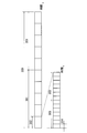
- FIG. 3 is a diagram showing a configuration of the TDD frame 300.
- the TDD frame 300 is composed of two half frames 301.
- Each half frame 301 is composed of five subframes 302. That is, the TDD frame 300 is composed of ten subframes 302.
- the time length of the subframe 302 is 1 ms.
- the ten subframes 302 constituting the TDD frame 300 may be referred to as the 0th to ninth subframes 302 in order from the top.
- the time length of one TDD frame 300 is called “one frame time”
- the time length of five consecutive subframes 302 is called “half frame time”.
- Each subframe 302 includes two slots 303 in the time direction.
- Each slot 303 is composed of seven symbol periods 304. Therefore, each subframe 302 includes 14 symbol periods 304 in the time direction.
- the symbol period 304 is one symbol period of OFDM symbols in OFDMA downlink communication, and one symbol period of DFTS (Discrete Fourier Transform Spread) -OFDM symbols in SC-FDMA uplink communication.
- DFTS Discrete Fourier Transform Spread
- the TDD frame 300 configured as described above includes a subframe 302 dedicated for uplink communication and a subframe 302 dedicated for downlink communication.
- the subframe 302 dedicated to uplink communication is referred to as “uplink subframe 302”
- the subframe 302 dedicated to downlink communication is referred to as “downlink subframe 302”.
- the communication terminal 2 transmits data to the base station 1 in the uplink subframe 302, and the base station 1 transmits data to the communication terminal 2 in the downlink subframe 302.
- a region (radio resource) including a frequency bandwidth of 180 kHz in the frequency direction and including seven symbol periods 304 (one slot 303) in the time direction is referred to as a “resource block (RB)”.
- the resource block includes 12 subcarriers.
- RB indicates the frequency band of the resource block.
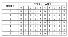
- FIG. 4 is a diagram showing the seven types of configurations.
- LTE defines the configurations of the TDD frames 300 from No. 0 to No. 6.
- the subframe 302 indicated by “D” means the downlink subframe 302
- the subframe 302 indicated by “U” means the uplink subframe 302.
- a subframe 302 indicated by “S” means a subframe 302 in which switching from downlink communication to uplink communication is performed in the communication system 100. This subframe 302 is referred to as a “special subframe 302”.
- the 0th and 5th subframes 302 are downstream subframes 302, and the 2nd to 4th subframes 302 and the 7th to 9th subframes 302 are upstream. It is a subframe 302, and the first and sixth subframes 302 are special subframes 302.
- the 0th subframe 302 and the fourth to ninth subframes 302 are downstream subframes 302, and the second and third subframes 302 are upstream subframes 302.
- the first subframe 302 is the special subframe 302. In communication system 100 according to the present embodiment, for example, TDD frame 300 having the first configuration is used.
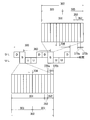
- FIG. 5 is a diagram showing in detail the configuration of the TDD frame 300 having the first configuration.
- the special subframe 302 includes a downlink pilot time slot (DwPTS) 351, a guard time (GP) 350, and an uplink pilot time slot (UpPTS) 352 in the time direction.
- the guard time 350 is a no-signal period necessary for switching from downlink communication to uplink communication, and is not used for communication.
- a plurality of types of combinations are defined for combinations of time lengths of the downlink pilot time slot 351, the guard time 350, and the uplink pilot time slot 352.
- the time length of the downlink pilot time slot 351 is set to 11 symbol periods 304
- the time length of the uplink pilot time slot 352 is set to 2 symbol periods 304.
- the communication system 100 it is possible to perform downlink communication not only in the downlink subframe 302 but also in the downlink pilot time slot 351 of the special subframe 302. Further, in the communication system 100, it is possible to perform uplink communication not only in the uplink subframe 302 but also in the uplink pilot time slot 352 of the special subframe 302.
- the base station 1 transmits data to the communication terminal 2 in each symbol period 304 of the downlink pilot time slot 351.
- Each communication terminal 2 transmits a known signal called SRS in one or both of the two symbol periods 304 of the uplink pilot time slot 352.
- the SRS is composed of a plurality of complex symbols that modulate a plurality of subcarriers.
- SRS transmitted in uplink pilot time slot 352 is used to calculate a transmission weight. That is, the communication unit 13 of the base station 1 can control the transmission directivity of the array antenna 110 based on the SRS that the communication terminal 2 transmits in the uplink pilot time slot 352.
- array transmission control the control of the transmission directivity of the array antenna 110 is referred to as “array transmission control”.
- the SRS can also be transmitted in the last symbol period 304 of the uplink subframe 302. That is, in the uplink subframe 302, the communication terminal 2 can transmit data in each symbol period 304 except for the last symbol period 304, and can transmit SRS in the last symbol period 304.
- the SRS transmitted in the uplink pilot time slot 352 is used.
- SRS refers to SRS transmitted using uplink pilot time slot 352.
- one transmission of SRS means transmission of SRS in one symbol period 304.
- first SRS uplink communication period 370a first SRS uplink communication period 370a
- second SRS uplink communication second SRS uplink communication
- the unit period 360 is used as a reference for assigning radio resources such as used downlink radio resources to the communication terminal 2. In the communication system 100, the unit period 360 appears repeatedly.
- each communication terminal 2 communicating with the base station 1 transmits the SRS at least once every unit period 360, for example, by the allocation of the uplink radio resource for use SRS by the radio resource allocation unit 122. . That is, each communication terminal 2 that communicates with the base station 1 transmits one of the first SRS uplink communication period 370a and the second SRS uplink communication period 370b included in the unit period 360 in each unit period 360, or SRS is transmitted in both. Since the length of the unit period 360 is 5 ms, hereinafter, transmission of the SRS once every unit period 360 by the communication terminal 2 is referred to as “5-ms periodic transmission”. In addition, the communication terminal 2 transmitting SRS twice for each unit period 360 is referred to as “shortest period transmission”.
- the base station 1 can also allocate the uplink radio resource for use SRS to the communication terminal 2 so that the communication terminal 2 transmits the SRS once every plural unit periods 360.
- the base station 1 can also allocate the uplink radio resource for use SRS to the communication terminal 2 so that the communication terminal 2 transmits the SRS once every plural unit periods 360.
- only 5 ms periodic transmission and shortest periodic transmission are used.
- the frequency band 450 (hereinafter referred to as "SRS transmittable band 450") that the communication terminal 2 can use for SRS transmission is frequency hopped every unit period 360.
- FIG. 6 is a diagram showing how the SRS transmittable band 450 is frequency hopped.
- the SRS transmittable band 450 is arranged alternately at the high frequency side and the low frequency side in the system band 400 for each unit period 360. Therefore, in each unit period 360, the high-frequency side end or the low-frequency side end in the system band 400 is a band that cannot be used for SRS transmission.
- this band is referred to as “SRS transmission disabled band”.
- Each base station 1 cannot allocate an uplink radio resource including a frequency band included in the SRS transmission disabled band in the frequency direction to the communication terminal 2 as an uplink radio resource for use SRS.
- the SRS transmission impossible band is the same in each base station 1. Therefore, in each unit period 360, an SRS transmission impossible band that a certain base station 1 cannot allocate to the communication terminal 2 for SRS transmission, and a peripheral base station 1 located in the vicinity of the base station 1 are communication terminals. 2 coincides with the SRS transmission impossible band that cannot be assigned for SRS transmission.
- the system bandwidth 400 when the system bandwidth is 10 MHz, the system bandwidth 400 includes 50 RBs.
- the bandwidth of the SRS transmittable band 450 is a frequency bandwidth for 40 RBs
- the bandwidth of the SRS transmission disabled band is a frequency bandwidth for 10 RBs.
- numbers from 0 to 49 are assigned to the 50 RBs arranged in the frequency direction in order from the lowest frequency, and the operation of the communication system 100 will be described below using these numbers. is there.
- the parameter k TC can take a value of “0” or “1”.
- SRS1 a plurality of subcarriers SC0 used for transmitting the SRS0 and a plurality of subcarriers SC1 used for transmitting the SRS1 are alternately arranged. Therefore, the carrier frequency of SRS0 and the carrier frequency of SRS1 do not overlap each other in the frequency direction.
- FIG. 7 shows a state where both SRS0 and SRS1 are transmitted in a certain frequency band 470.
- a plurality of subcarriers SC0 used for transmission of SRS0 are arranged every other subcarrier in the frequency direction.
- a plurality of subcarriers SC1 used for transmission of SRS1 are arranged every other subcarrier in the frequency direction.
- a plurality of subcarriers SC0 and a plurality of subcarriers SC1 included in the same frequency band 470 are alternately arranged in the frequency direction.
- the communication terminal 2 in the frequency band used for SRS transmission is used.
- Half of the subcarriers are used for SRS transmission.
- the communication terminal 2 that transmits SRS0 and the communication terminal 2 that transmits SRS1 are the same.
- the same frequency band can be used in the uplink communication period for SRS. From the base station 1 side, the base station 1 can distinguish SRS0 and SRS1 transmitted in the same frequency band in the same uplink communication period for SRS.
- each communication terminal 2 transmits SRS0 in at least one of the first SRS uplink communication period 370a and the second SRS uplink communication period 370b.
- the uplink radio resource specified by the first SRS uplink communication period 370a and the plurality of comb-shaped subcarriers SC0 included in the SRS transmittable band 450 and usable for transmission of SRS0 is referred to as “first”. This is referred to as “1SRS uplink radio resource 500a”. Further, the uplink radio resources specified by the second SRS uplink communication period 370b and the plurality of comb-shaped subcarriers SC0 included in the SRS transmittable band 450 that can be used for the transmission of SRS0 are designated as “first”. This is referred to as “2SRS uplink radio resource 500b”.
- FIG. 8 is a diagram illustrating the first SRS uplink radio resource 500a and the second SRS uplink radio resource 500b. As shown in FIG. 8, the first SRS uplink radio resource 500a and the second SRS uplink radio resource 500b match in the frequency direction, but are different from each other in the time direction. Hereinafter, when it is not necessary to distinguish these uplink radio resources, each is referred to as an “SRS uplink radio resource”.
- LTE eight types of code patterns composed of a plurality of SRS symbols constituting the SRS are defined.
- the eight types of code patterns employ eight types of code sequences that are orthogonal to each other.
- the communication terminal 2 transmits any one of 8 types of code patterns as SRS.
- SRS transmitted by a maximum of eight communication terminals 2 in the LTE standard. can be multiplexed. However, in this embodiment, SRS multiplexing is not performed.
- first assignable SRS uplink radio resource 600a that can be assigned to communication terminal 2 as an uplink radio resource for use SRS is determined for first SRS uplink radio resource 500a. It has been.
- a second allocable SRS uplink radio resource 600b that can be allocated to the communication terminal 2 as a used SRS uplink radio resource is defined for the second SRS uplink radio resource 500b.
- the frequency band of the first assignable SRS uplink radio resource 600a and the frequency band of the second assignable SRS uplink radio resource 600b are different from each other.
- the frequency bandwidth of each of the first assignable uplink radio resource for SRS 600a and the second assignable uplink radio resource for SRS 600b is, for example, a bandwidth of 20 RBs. Therefore, in each unit period 360, the frequency bands of the first assignable SRS uplink radio resource 600a and the second assignable SRS uplink radio resource 600b are continuous and occupy the entire region of the SRS transmittable band 450. .
- Each base station 1 allocates an uplink radio resource for use SRS from at least one of the first assignable SRS uplink radio resource 600a and the second assignable SRS uplink radio resource 600b in the unit period 360 to the communication terminal 2. .
- each is referred to as an “assignable SRS uplink radio resource”.
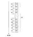
- FIG. 9 shows the state.
- FIG. 9 shows each subframe 302 in a plurality of continuous unit periods 360.
- the horizontal direction indicates the time direction
- the vertical direction indicates the frequency direction.
- the numbers 0 to 49 shown on the leftmost side of FIG. 9 indicate the numbers of 50 RBs arranged in the frequency direction.
- SP shown in FIG. 9 means a special subframe 302
- Up means an uplink pilot time slot (UpPTS) 352
- Dw means a downlink pilot time slot (DwPTS) 351.
- UL and “DL” shown in FIG. 9 mean the uplink subframe 302 and the downlink subframe 302, respectively.
- the frequency band of the uplink radio resource for SRS that can be allocated is arranged so as to be alternately arranged on the high frequency side and the low frequency side in the SRS transmittable band 450 for each unit period 360. It has become.
- the frequency band of the first allocable SRS uplink radio resource 600a is related to the case where the SRS transmittable band 450 in the special subframe 302 to which the first assignable SRS belongs is located on the low frequency side of the system band.
- the SRS transmittable band 450 is arranged close to the low frequency side and the SRS transmittable band 450 is located on the high frequency side of the system band, the SRS transmittable band 450 is arranged close to the high frequency side.
- the frequency band of the first assignable uplink radio resource for SRS 600a is alternately arranged on the high frequency side and the low frequency side in the system band for each unit period 360.
- end hopping such frequency hopping in the frequency band of the first assignable uplink radio resource for SRS 600a is referred to as “end hopping”.
- the SRS transmittable band 450 in the special subframe 302 to which the second allocatable SRS uplink radio resource 600b belongs is located on the low frequency side of the system band
- the SRS transmission When the SRS transmittable band 450 is located on the high frequency side of the system band, the SRS transmittable band 450 is arranged close to the low frequency side.
- the frequency band of the second allocatable uplink radio resource for SRS 600b is one unit period 360 in the frequency band composed of 30 RBs in the central part in the system band (from RB 10 to 39 RB). They are arranged alternately on the high frequency side and the low frequency side.
- such frequency hopping in the frequency band of the second assignable uplink radio resource for SRS 600b is referred to as “medium hopping”.
- the two unit periods 360 will be the previous unit period.
- the frequency band of the second assignable SRS uplink radio lease 600b in 360 is the frequency band of the first assignable SRS uplink radio resource 600a and the second assignable SRS uplink radio resource 600b in the subsequent unit period 360 ( It is included in 40 consecutive RBs).
- the frequency band of the first assignable SRS uplink radio lease 600a in the previous unit period 360 includes the first assignable SRS uplink radio resource 600a and the second assignable SRS uplink radio in the subsequent unit period 360.
- a partial frequency band 601a not included in the frequency band of the resource 600b is included.
- the partial frequency band 601a included in the frequency band of the first assignable SRS uplink radio resource 600a in the first and last unit periods 360 is a frequency band from the 34th RB to the 49th RB.
- the partial frequency band 601a included in the frequency band of the first assignable SRS uplink radio resource 600a in the middle unit period 360 is a frequency band from the 0th RB to the 9th RB.
- the frequency band (hereinafter referred to as “SRS band”) used by one communication terminal 2 for one transmission of SRS is determined for each unit period 360.
- Frequency hopping is performed within the frequency band of the assignable uplink radio resource for SRS.
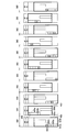
- 10 and 11 are diagrams illustrating how the SRS band for a certain communication terminal 2 undergoes frequency hopping.
- target communication terminal 2 the communication terminal 2 to be described is referred to as “target communication terminal 2”.
- a plurality of bandwidths having different sizes are defined as bandwidths that can be set as the transmission frequency bandwidth of the SRS.
- three types of bandwidths are defined: a bandwidth for 40 RBs, a bandwidth for 20 RBs, and a bandwidth for 4 RBs.
- the minimum bandwidth among these bandwidths that is, the bandwidth for four RBs, is set as the transmission frequency bandwidth of SRS.
- the frequency bandwidth of the uplink radio resource for use SRS allocated to each communication terminal 2 is set to a bandwidth corresponding to four RBs.
- the bandwidth for x RBs may be simply referred to as “xRB”.
- the SRS band 650 for the target communication terminal 2 is indicated by hatching.
- the used SRS uplink radio resource having a frequency bandwidth of 4 RBs is allocated to the target communication terminal 2 from the first allocatable SRS uplink radio resource 600a.
- the used SRS uplink radio resource having a frequency bandwidth of 4 RBs is allocated to the target communication terminal 2 from the second allocatable SRS uplink radio resource 600b.
- the SRS band 650 performs frequency hopping within the frequency band of the assignable SRS uplink radio resource every two unit periods 360 (every 10 ms).
- the SRS band 650 returns to the original frequency band every 10 unit periods 360 (every 50 ms).
- the SRS band 650 for the target communication terminal 2 to which the useable SRS radio resource is assigned from the first assignable SRS uplink radio resource 600a is the first assignable SRS uplink radio resource. Every time the frequency band of the radio resource 600a is positioned on the low frequency side of the SRS transmittable band 450, frequency hopping is performed within the frequency band of the first assignable SRS uplink radio resource 600a. As shown in FIG. 11, the SRS band 650 for the target communication terminal 2 to which the used SRS radio resource is allocated from the second allocatable SRS uplink radio resource 600b is the second allocatable SRS uplink radio resource 600b. Frequency hopping is performed within the frequency band of the second allocatable uplink radio resource for SRS 600b each time the frequency band becomes higher frequency side of the SRS transmittable band 450.
- the SRS band 650 when the frequency band of the uplink radio resource for SRS that can be allocated is divided into 4 RBs, five partial frequency bands are obtained.
- the SRS band 650 becomes the partial frequency in the order of the first, third, fifth, second, fourth partial frequency bands. It changes to match the band and repeats this. Note that when the target communication terminal 2 starts transmitting SRS, the SRS band 650 does not necessarily start from the first partial frequency band, and may start from the fifth partial frequency band, for example.
- the radio resource allocation unit 122 determines which of the 5 ms periodic transmission and the shortest periodic transmission is to be executed for each communication terminal 2 with which the base station 1 communicates.
- the radio resource allocating unit 122 determines that the target communication terminal 2 performs the 5 ms periodic transmission
- the target communication terminal 2 determines that the target communication terminal 2 uses the first allocatable SRS uplink radio resource 600a and the second allocatable SRS uplink radio resource 600b.
- An assignable SRS uplink radio resource to be used for SRS transmission is determined.
- the radio resource allocating unit 122 determines to execute the minimum period transmission for the target communication terminal 2
- the assignable SRS uplink radio resource used for the SRS transmission by the target communication terminal 2 is assigned to the first assignable SRS. It determines to both the uplink radio resource 600a for uplink and the uplink radio resource 600b for 2nd assignable SRS.
- the radio resource allocation unit 122 determines the transmission frequency bandwidth of the SRS, the frequency hopping mode of the SRS band 650, the value of the parameter k TC , and the like. As a result, for each communication terminal 2 with which the base station 1 communicates, when the communication terminal 2 executes 5 ms periodic transmission, the communication terminal 2 is used from one assignable uplink radio resource for SRS to be used. An uplink radio resource for SRS is allocated. On the other hand, when the communication terminal 2 is caused to execute the shortest cycle transmission, the first allocable SRS uplink radio resource 600a and the second allocable SRS uplink radio resource 600b are assigned to the communication terminal 2. The uplink radio resource for use SRS is allocated.
- the transmission frequency bandwidth of SRS is set to 4 RBs, and the value of parameter k TC is set to “0”. Then, the frequency hopping mode of the SRS band 650 is determined such that the SRS band 650 is frequency hopped as shown in FIGS.
- the radio resource assignment unit 122 assigns the uplink radio resource for use SRS to the target communication terminal 2 by determining the transmission mode of the SRS for the target communication terminal 2.
- the transmission signal generation unit 120 uses the control data for notifying the target communication terminal 2 of the uplink radio resources for use SRS allocated to the target communication terminal 2 by the radio resource allocation unit 122, in other words, the radio resource allocation unit 122
- a transmission signal including control data (hereinafter referred to as “SRS control data”) for notifying the target communication terminal 2 of the determined transmission mode of the SRS transmitted by the target communication terminal 2 is generated.
- This transmission signal is transmitted from the communication unit 13 to the target communication terminal 2 using the downlink subframe 302.
- SRS control data is transmitted to each communication terminal 2, and each communication terminal 2 can know the uplink radio resource used when transmitting SRS. In other words, each communication terminal 2 can know the transmission mode of the SRS transmitted by itself.
- Each communication terminal 2 transmits the SRS using the uplink radio resource for use SRS notified from the base station 1.
- the SRS control data includes transmission start data for instructing the start of SRS transmission or transmission stop data for instructing to stop the transmission of SRS.
- the communication terminal 2 that has not transmitted the SRS receives the SRS control data including the transmission start data
- the communication terminal 2 starts the transmission of the SRS using the used SRS uplink radio resource notified by the SRS control data.
- the communication terminal 2 which is transmitting SRS receives SRS control data including transmission stop data
- the transmission of SRS is stopped.
- SRS control data for notifying the new uplink radio resource for use SRS is notified to the communication terminal 2.
- the SRS control data is called “RRCConnectionReconfigurationRemessage” in LTE.
- FIG. 12 is a diagram showing the series of operations.
- a transmission signal including SRS control data is transmitted from the base station 1 to the target communication terminal 2.
- the target communication terminal 2 has successfully received the SRS control data.
- a transmission signal including response data for notifying is transmitted to the base station 1. This response data is called “RRCConnectionReconfigurationComplete message”.
- the target communication terminal 2 that has transmitted the response data is notified in the next Nth TDD frame 300 or later using the uplink radio resource for use SRS indicated by the received SRS control data, in other words, the SRS control data.
- SRS is transmitted based on the transmission mode.
- the target communication terminal 2 transmits the response data in the (N ⁇ 1) th TDD frame 300, but the target communication terminal 2 transmits the response data in the TDD frame 300 after that. May be sent.
- the communication terminal 2 transmitting the SRS receives SRS control data for notifying the uplink radio resource for use SRS newly assigned to the communication terminal 2, the SRS control data Until the SRS is transmitted using the uplink radio resource for new use SRS notified by (up to the second special subframe 302 of the (N ⁇ 1) th TDD frame 300 in the example of FIG. 12) The SRS is transmitted by using the uplink radio resource for SRS used until then.
- the target communication terminal 2 in the TDD frame 300 after the TDD frame 300 is at least two. Transmits SRS based on the SRS control data. Therefore, when the base station 1 instructs the target communication terminal 2 to start SRS transmission or when the base station 1 instructs the target communication terminal 2 to change the transmission mode of SRS, the base station 1 transmits SRS control data to the target communication terminal 2. Then, it takes a certain amount of time to receive the SRS transmitted from the target communication terminal 2 based on the SRS control data.
- the communication system 100 operates in the same manner when the base station 1 instructs the communication terminal 2 that is transmitting SRS to stop transmission of SRS. For example, when SRS control data including transmission stop data is transmitted from the base station 1 to the target communication terminal 2 in the downlink subframe 302 located at the end of the (N-2) th TDD frame 300, the next In the eighth uplink subframe 302 (seventh subframe 302) from the top of the (N ⁇ 1) th TDD frame 300, the target communication terminal 2 notifies that the SRS control data has been normally received. Response data is transmitted to the base station 1. The target communication terminal 2 that has transmitted the response data stops SRS transmission when the next Nth TDD frame 300 is reached.
- the base station 1 instructs the target communication terminal 2 to stop the transmission of SRS
- the transmission of the SRS in the target communication terminal 2 is stopped after transmitting the SRS control data to the target communication terminal 2. It will take some time to do.
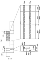
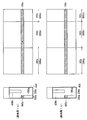
- FIG. 13 is a diagram for explaining a method of allocating used downlink radio resources to the communication terminal 2 in the present embodiment.
- FIG. 13 shows the use downlink radio resource 700a allocated to the communication terminal 2 of terminal number A that transmits SRS in a certain unit period 360 and the communication terminal 2 of terminal number B that transmits SRS in the unit period 360.
- a use downlink radio resource 700b allocated to the radio network is shown.
- the communication terminal 2 with terminal number A transmits the SRS using the uplink radio resource for use SRS 680a included in the first assignable radio resource for SRS 600a
- the communication terminal with terminal number B 2 transmits the SRS by using the uplink radio resource for use SRS 680b included in the second assignable uplink radio resource for SRS 600b.
- the target unit period 360 may be referred to as “target unit period 360”.
- the portion of the special subframe 302 that includes the downlink pilot time slot 351 in the time direction is not the downlink subframe 302, but hereinafter, for convenience of explanation, the portion that includes the downlink subframe 302 is also included.
- a portion including the downlink pilot time slot 351 in the time direction among the two downlink subframes 302 and special subframes 302 included in the unit period 360 is a first downlink subframe 302a, a second downlink subframe 302b, and a third These are respectively called downlink subframes 302c.
- the 14 symbol periods 304 included in the time direction by the first downlink subframe 302a and the second downlink subframe 302b are referred to as a “first downlink communication period 800a” and a “second downlink communication period 800b”, respectively.
- the eleven symbol periods 304 included in the time direction of the three downlink subframes 302c are referred to as “third downlink communication period 800c”.
- the first downlink communication period 800a, the second downlink communication period 800b, and the second downlink communication period 800b included in the unit period 360 are described in the time direction for each communication terminal 2 that transmits the SRS in the unit period 360.
- Downlink radio resources including each of the three downlink communication periods 800c are allocated as used downlink radio resources.
- downlink radio including a frequency band included in the SRS transmission frequency band (SRS band 650). Resources are allocated as used downlink radio resources.
- the frequency band included in the transmission frequency band of the SRS is included in the frequency direction, and the first frequency included in the unit period 360 is included.
- a downlink radio resource including each of the first downlink communication period 800a, the second downlink communication period 800b, and the third downlink communication period 800c in the time direction is allocated as a used downlink radio resource.
- the frequency band included in the SRS band 650a for the communication terminal 2 is included in the frequency direction, and the first downlink communication period 800a and the second downlink communication are included.
- a downlink radio resource including the period 800b and the third downlink communication period 800c in the time direction is allocated as the used downlink radio resource 700a.
- the frequency band included in the SRS band 650b for the communication terminal 2 is included in the frequency direction, and the first downlink communication period 800a, the second downlink communication period 800b, and the first A downlink radio resource including the three downlink communication periods 800c in the time direction is allocated as a used downlink radio resource 700b.
- the used downlink radio resource is allocated to the communication terminal 2 for each allocation unit.
- the communication terminal 2 that transmits the first downlink communication period 800a, the second downlink communication period 800b, and the second downlink communication period 800b that include one RB adjacent to the transmission frequency band of the SRS in the frequency direction and are included in the unit period 360.
- a downlink radio resource including a three downlink communication period 800c in the time direction is also assigned as a used downlink radio resource. This point will be described in detail below.
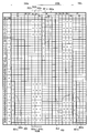
- FIG. 14 is a diagram showing an example of allocation of used downlink radio resources to the communication terminal 2 in a plurality of unit periods 360.
- FIG. 14 shows an example of allocation of used downlink radio resources to communication terminals 2 having terminal numbers A to E that transmit SRS using a part of first assignable SRS uplink radio resource 600a.
- the three unit periods 360 shown in FIG. 14 are referred to as a unit period 360a, a unit period 360b, and a unit period 360c, respectively, in order from the top.
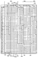
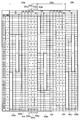
- a system band composed of 50 RBs is divided into 17 partial frequency bands.
- Each of the 16 partial frequency bands from the low frequency side included in the system band is 3 RBs, and the remaining one partial frequency band included in the system band is 2 RBs. Yes.
- the numbers from 0 to 16 are assigned to the 17 partial frequency bands constituting the system band in order from the low frequency side.
- this partial frequency band is referred to as RBG (resource block group).
- the used downlink radio resource is allocated to the communication terminal 2 for each RGB.
- the communication terminal 2 that transmits the SRS including the 10th RGB in the transmission frequency band includes the 10th RBG in the frequency direction. Downlink radio resources are allocated.
- the 11th RBG is transmitted to the communication terminal 2 of the terminal number B that transmits the SRS including a part of the 11th RBG and a part of the 12th RBG in the transmission frequency band by 2 RBs.
- used downlink radio resources including the 12th resource block in the frequency direction are allocated.
- a used downlink radio resource including one RB adjacent to the transmission frequency band on the high frequency side in the frequency direction are allocated.
- the 15th RBG and the 16th RBG Used downlink radio resources including the frequency domain in the frequency direction.
- the used downlink radio resource including the transmission frequency band of the SRS transmitted by the communication terminal 2 in the frequency direction, and one RB adjacent to the transmission frequency band on the low frequency side
- used downlink radio resources including the frequency domain in the frequency direction.
- the communication terminal 2 of terminal number B that transmits an SRS that includes a part of the first RBG and a part of the second RBG in the transmission frequency band by 2 RBs.
- a use downlink radio resource including the first RBG and the second RBG in the frequency direction is allocated.
- a used downlink radio resource including one RB adjacent to the transmission frequency band on the high frequency side in the frequency direction is allocated.
- the use downlink radio resource including the third RBG in the frequency direction is allocated to the communication terminal 2 having the terminal number C that transmits the SRS including the third RBG in the transmission frequency band.
- the 5th RBG is transmitted to the communication terminal 2 of the terminal number E that transmits the SRS that includes a part of the 5th RBG and a part of the 6th RBG in the transmission frequency band by 2 RBs.
- the used downlink radio resource including the 6th RBG in the frequency direction are allocated.
- a used downlink radio resource including one RB adjacent to the transmission frequency band on the high frequency side in the frequency direction are allocated.
- the transmission frequency band of the SRS transmitted by the communication terminal 2 is changed. Not only used downlink radio resources including the included frequency band in the frequency direction, but also one RB adjacent to the transmission frequency band on the low frequency side and one RB adjacent to the transmission frequency band on the high frequency side.
- the used downlink radio resource including at least one of the RBs in the frequency direction is allocated. That is, in the present embodiment, with respect to the communication terminal 2 that transmits the SRS in the unit period 360, one RBG is transmitted in the frequency direction from the downlink radio resource of the unit period 360 in association with the transmission frequency band of the SRS.
- FIG. 14 shows an example of allocation of used downlink radio resources to the communication terminal 2 that transmits the SRS using a part of the first assignable SRS downlink radio resource 600a, but the second assignable SRS is shown. The same applies to the allocation of the used downlink radio resource to the communication terminal 2 that transmits the SRS using a part of the downlink radio resource 600b for use.
- the first assignable in the subsequent unit period 360 is possible.
- Communication terminal 2 that transmits SRS using a frequency band included in partial frequency band 601a not included in the frequency band (SRS transmittable band 450) of SRS uplink radio resource 600a and second assignable SRS uplink radio resource 600b
- SRS transmittable band 450 the frequency band included in partial frequency band 601a not included in the frequency band (SRS transmittable band 450) of SRS uplink radio resource 600a and second assignable SRS uplink radio resource 600b
- the used downlink radio resource is allocated from the downlink radio resource of the previous unit period 360 but also the used downlink radio resource is allocated from the downlink radio resource of the subsequent unit period 360 as described above.
- the portion not included in the SRS transmittable band 450 in the subsequent unit period 360 is referred to as “continuous allocation terminal 2” in the unit period 360 ahead.
- the used downlink radio resource see FIG.
- a used downlink radio resource allocated from a downlink radio resource in a unit period next to a certain unit period 360 is referred to as “additional used downlink radio resource”.
- the frequency unit includes the SRS transmission frequency band transmitted by the continuously allocated terminal 2 in the certain unit period 360, and is the next unit period after the certain unit period 360.
- a downlink radio resource including the first downlink communication period 800a, the second downlink communication period 800b, and the third downlink communication period 800c included in 360 in the time direction is allocated as an additional use downlink radio resource, or the SRS
- the first downlink included in the next unit period 360 includes a transmission frequency band and at least one of one RB adjacent to the transmission frequency band on the low frequency side and one RB adjacent to the transmission frequency band on the high frequency side.
- a communication period 800a, a second downlink communication period 800b, and a third downlink communication period 800c are included in the time direction.
- Ri radio resource is allocated as an additional use downlink radio resource.
- the unit period 360 next to the certain unit period 360 is associated with the transmission frequency band of the SRS transmitted by the continuously allocated terminal 2 in the certain unit period 360.
- the additional used downlink radio resource includes only the transmission frequency band of the SRS in the frequency direction. Or the frequency band of the SRS and one RB adjacent thereto are set.
- FIG. 15 is obtained by adding the additional downlink radio resource used in FIG. 14 described above.
- the basic use downlink radio resource is allocated from the downlink radio resource of the unit period 360a but also the next one.
- An additional use downlink radio resource is allocated from the downlink radio resource of the unit period 360b.
- this additional use downlink radio resource includes the 13th RBG in the frequency direction, the first downlink communication period 800a, the second downlink communication period 800b, and the third downlink communication included in the unit period 360b.
- a period 800c is included in the time direction.
- a basic use downlink radio resource is allocated from the downlink radio resource of the unit period 360a, and an additional use downlink radio resource is allocated from the downlink radio resource of the next unit period 360b.
- the communication terminal 2 with the terminal number C transmits the SRS using the RBs from the 0th to the 3rd.
- Communication terminal 2 with terminal number D is transmitting SRS using RBs of No. 7 to No. 7.
- the downlink radio resources including the first downlink communication period 800a to the third downlink communication period 800c included in the unit period 360a in the time direction and the 0th to 2nd RBs (0th RBG) in the frequency direction are unit periods.
- the downlink radio including the first downlink communication period 800a to the third downlink communication period 800c included in the unit period 360a in the time direction and the third to eighth RBs (the first and second RBGs) in the frequency direction.
- the resource is the communication terminal 2 of the terminal number D that transmits the SRS using the RBs 4 to 7 in the unit period 360 immediately before the unit period 360a (the continuously allocated terminal in the previous unit period 360) It is assigned as an additional downlink radio resource for 2).
- the communication terminal 2 when performing downlink communication with the communication terminal 2 using the used downlink radio resource including one RBG in the frequency direction, the communication terminal 2 has a frequency band included in the RBG. Is transmitted in the unit period 360, array transmission control is performed based on the SRS. On the other hand, in the unit period 360, when performing downlink communication with the communication terminal 2 using the used downlink radio resource including one RBG in the frequency direction, the communication terminal 2 transmits the frequency band included in the RBG as a transmission frequency. When the SRS included in the band is not transmitted in the unit period 360, the frequency band included in the RBG transmitted by the communication terminal 2 is transmitted in the unit period 360 immediately before the unit period 360. Array transmission control is performed based on the SRS included in the frequency band.
- array transmission control according to the present embodiment will be described in detail with reference to FIG.
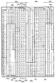
- FIG. 16 shows an example of allocation of downlink radio resources used for each communication terminal 2 when the base station 1 performs downlink communication with 10 communication terminals 2 with terminal numbers A to J.
- An example of allocation of used downlink radio resources to the communication terminals 2 with terminal numbers A to E in FIG. 16 is the same as that in FIG. 15 described above.
- the communication terminals 2 with terminal numbers A to E transmit SRS using a part of the first assignable SRS uplink radio resource 600a, and the communication terminals 2 with terminal numbers F to J receive the second assignable SRS uplink.
- the SRS is transmitted using a part of the radio resource 600b.
- the communication terminal 2 when performing downlink communication with the communication terminal 2 with the terminal number A using the used downlink radio resource including the 10th RBG in the frequency direction, the communication terminal 2 Since the SRS including the frequency band (30th to 32nd RBs) included in the 10th RBG in the transmission frequency band is transmitted in the unit period 360a, array transmission control is performed based on the SRS.
- the communication terminal 2 when performing downlink communication with the communication terminal 2 with the terminal number F using the used downlink radio resource including the third RBG in the frequency direction, the communication terminal 2 becomes the third RBG. Since the SRS including the included frequency bands (10th and 11th RBs) in the transmission frequency band is transmitted in the unit period 360a, array transmission control is performed based on the SRS.
- the communication terminal 2 when performing downlink communication with the communication terminal 2 with the terminal number F using the used downlink radio resource including the 4th RBG in the frequency direction, the communication terminal 2 becomes the 4th RBG. Since the SRS including the included frequency bands (No. 12 and No. 13 RB) in the transmission frequency band is transmitted in the unit period 360a, array transmission control is performed based on the SRS.
- the communication terminal 2 when performing downlink communication with the communication terminal 2 having the terminal number D using the used downlink radio resource including the fourth RBG in the frequency direction, the communication terminal 2 is 4 Since the SRS including the frequency band included in the number RBG (Nos. 12-14) in the transmission frequency band is transmitted in the unit period 360b, array transmission control is performed based on the SRS.
- the communication terminal 2 when performing downlink communication with the communication terminal 2 with the terminal number I using the used downlink radio resource including the 11th RBG in the frequency direction, the communication terminal 2 becomes the 11th RBG. Since the SRS including the included frequency band (RB of No. 33 to No. 35) in the transmission frequency band is transmitted in the unit period 360b, array transmission control is performed based on the SRS.
- the communication terminal having the terminal number C 2 when performing downlink communication with the communication terminal 2 having the terminal number C using the used downlink radio resource including the 13th RBG in the frequency direction, the communication terminal having the terminal number C 2 does not transmit the SRS including the frequency band included in the 13th RBG in the transmission frequency band in the unit period 360b.
- the frequency band (39th to 41st RBs) included in the 13th RBG transmitted by the communication terminal 2 with the terminal number C is transmitted.
- Array transmission control is performed based on the SRS included in the frequency band.
- the communication terminal 2 with the terminal number E when performing downlink communication with the communication terminal 2 with the terminal number E using the used downlink radio resource including the 15th RBG in the frequency direction, the communication terminal 2 with the terminal number E
- the SRS including the frequency band included in the RBG in the transmission frequency band is not transmitted in the unit period 360b.
- the frequency band (the 46th and 47th RBs) included in the 15th RBG transmitted by the communication terminal 2 with the terminal number E is transmitted.
- Array transmission control is performed based on the SRS included in the frequency band.
- the communication terminal 2 that performs downlink communication using the used downlink radio resource allocated from the downlink radio resource in a certain unit period 360 is the unit.
- the communication terminal 2 that performs downlink communication using the used downlink radio resource allocated from the downlink radio resource of a certain unit period 360 has a frequency band included in the frequency band of the used downlink radio resource in the unit period 360.
- the frequency band included in the frequency band of the used downlink radio resource transmitted by the communication terminal 2 in the unit period 360 before the unit period 360 is transmitted.
- Array transmission control is performed based on the SRS included in the frequency band.
- each base station 1 in the unit period 360 (unit periods 360a and 360c in FIG. 16) in which the SRS transmittable band 450 is arranged close to the high frequency side, SRS transmission disabled bands (0th to 9th RBs)
- the communication terminal 2 transmits in the unit period 360 one before the unit period 360.
- Array transmission control is performed based on the SRS to be performed. Further, in each base station 1, in the unit period 360 (unit period 360b in FIG.
- the SRS transmittable band 450 is arranged close to the low frequency side, the SRS transmission disabled band (40th to 49th RB) and
- the communication terminal 2 is in the unit period 360 immediately before the unit period 360.
- Array transmission control is performed based on the SRS to be transmitted.
- null steering and beam forming are performed simultaneously.
- the reception weight is updated a plurality of times using a sequential update algorithm such as an RLS (Recursive Least-Squares) algorithm, and the transmission weight is obtained based on the reception weight after the update is completed. Perform both beamforming at the same time.
- RLS Recursive Least-Squares
- a transmission weight is obtained for each RB, for example.
- the transmission frequency band of SRS transmitted by communication terminal 2 is composed of four RBs
- a transmission weight is obtained for each of the four RBs.
- the transmission weight for one RB related to the target communication terminal 2 is updated six times based on the six complex symbols constituting the SRS transmitted by the target communication terminal 2 using the one RB.
- the transmission weight is obtained based on the reception weight after the update is completed. Since one RB includes 12 subcarriers, it is possible to transmit 12 complex symbols using one RB, but one communication terminal 2 is used for SRS transmission. Since the plurality of subcarriers are arranged in a comb shape in the frequency direction, the SRS transmitted by the communication terminal 2 using one RB is composed of six complex symbols.
- the target communication when performing downlink communication with the target communication terminal 2 using the used downlink radio resource including one RB in the frequency direction, in principle, the target communication is performed using the RB.
- the transmission weight obtained based on the SRS transmitted by the terminal 2 is set to the transmission signal transmitted using the used downlink radio resource.
- the number 30 when downlink communication is performed with the communication terminal 2 of the terminal number A in the unit period 360a using the used downlink radio resource including the RB of the number 30 in the frequency direction, the number 30 The transmission weight obtained based on the SRS transmitted by the communication terminal 2 with the terminal number A in the unit period 360a using the RB is set to the transmission signal transmitted using the used downlink radio resource.
- the RB with the number 42 is used.
- the transmission weight obtained based on the SRS transmitted by the communication terminal 2 with the terminal number D in the previous unit period 360a is set to the transmission signal transmitted using the used downlink radio resource.
- the used downlink radio including one RB adjacent to the transmission frequency band of the SRS transmitted by the communication terminal 2 on the low frequency side or the high frequency side in the frequency direction. Resources may be allocated.
- the communication terminal 2 uses the transmission weight obtained based on the SRS transmitted using one RB adjacent to one RB included in the frequency direction of the use downlink radio resource in the use direction. It sets to the transmission signal transmitted using a downlink radio
- the number 9 adjacent on the low frequency side to the SRS transmission frequency band (10th to 13th RBs) transmitted by the communication terminal 2 with the terminal number F in the unit period 360a is adjacent to the 9th RB including the use downlink radio resource in the frequency direction.
- the transmission weight obtained based on the SRS transmitted by the communication terminal 2 having the terminal number F in the unit period 360a using the 10th RB is set to the transmission signal transmitted using the used downlink radio resource.
- each base station 1 of the communication system 100 when performing downlink communication with the communication terminal 2 using the used downlink radio resource including one RBG in the frequency direction, since the base station 1 performs the array transmission control based on the SRS including the frequency band included in the RBG transmitted by the communication terminal 2 in the transmission frequency band, when each base station 1 performs downlink communication with the communication terminal 2, A beam related to the transmission directivity of the array antenna 110 can be appropriately directed to the communication terminal 2.
- the frequency band of the used downlink radio resource and the downlink communication are used. Since the transmission frequency band of the SRS transmitted by the communication terminal 2 used in the array transmission control in FIG. 2 is substantially the same, each base station 1 performs the array antenna 110 when performing downlink communication with the communication terminal 2. Can be directed to the communication terminal 2 appropriately.
- each base station 1 of the communication system 100 as described above, the allocation of the uplink radio resource for use SRS to the communication terminal 2, the allocation of the downlink radio resource to be used for the communication terminal 2, and the array transmission control. Therefore, when each base station 1 performs downlink communication with the communication terminal 2, the transmission of the array antenna 110 to the communication terminal 2 communicating with the peripheral base station 1 located in the vicinity of the base station 1 is performed.
- the null related to directivity can be directed appropriately. This point will be described below.
- FIG. 17 and 18 are diagrams for explaining that the beam and null related to the transmission directivity of the array antenna 110 are appropriately controlled.
- FIG. 17 shows an example of allocation of used SRS uplink radio resources and used downlink radio resources in the base unit 1a and the base station 1b located in the vicinity thereof in the target unit period 360.
- FIG. 18 also shows beams and nulls related to transmission directivities in the base stations 1a and 1b in the target unit period 360.
- the base station 1 a transmits the SRS using the used SRS uplink radio resource 680 a included in the first assignable SRS uplink radio resource 600 a.
- Downlink communication is performed using the communication terminal 2 and the used downlink radio resource 700a.
- the base station 1b uses the communication terminal 2 with terminal number Z that transmits the SRS using the uplink radio resource for use SRS 680z included in the first assignable radio resource for SRS 600a and the use downlink radio resource 700z. Downlink communication is performed.
- the used downlink radio resource 700a and the used downlink radio resource 700z match.
- the SRS received by the base station 1a from the communication terminal 2 with the terminal number A in the uplink radio resource 680a for use SRS is the communication terminal 2 with the terminal number Z with which the base station 1b located around the base station 1a communicates.
- SRS transmitted by is included as an interference wave component. Therefore, the base station 1a calculates a transmission weight based on the SRS received from the communication terminal 2 with the terminal number A in the used SRS uplink radio resource 680a, and uses the used downlink radio resource 700a as a terminal number.
- the transmission signal is set to be transmitted to the communication terminal 2 of A, as shown in FIG.
- the beam 900a is directed to the communication terminal 2 having the terminal number A
- the null 901a is directed to the communication terminal 2 having the terminal number Z communicating with the base station 1b. Therefore, the base station 1a can reliably deliver the transmission signal to the communication terminal 2 to be communicated, and suppress the interference to the communication terminal 2 with which the neighboring base station 1b communicates. it can.
- a null is directed toward the communication terminal 2 with which the base station 1b communicates.
- the SRS received by the base station 1b from the communication terminal 2 with the terminal number Z in the used SRS uplink radio resource 680z is the communication terminal with the terminal number A with which the base station 1a located around the base station 1b communicates.
- SRS transmitted by 2 is included as an interference wave component. Therefore, the base station 1b calculates a transmission weight based on the SRS received from the communication terminal 2 with the terminal number Z in the used SRS uplink radio resource 680z, and uses the transmission downlink radio resource 700z to determine the transmission weight.
- the transmission signal is set to be transmitted to the communication terminal 2 of Z, as shown in FIG. 18, the transmission directivity at the array antenna 110 when the base station 1b transmits the transmission signal using the used downlink radio resource 700z.
- the beam 900b is directed to the communication terminal 2 having the terminal number Z, and the null 901b is directed to the communication terminal 2 having the terminal number A communicating with the base station 1a. Therefore, the base station 1b can reliably transmit the transmission signal to the communication terminal 2 to be communicated, and can suppress interference with the communication terminal 2 with which the neighboring base station 1a communicates. it can.
- each base station 1 can direct a beam to the communication terminal 2 that is a communication target, and can direct a null to the communication terminal 2 that is not a communication target. can do.
- the number of communication terminals 2 with which the communication unit 13 performs downlink communication is 4 RBs (SRS transmitted by the communication terminal 2) included in the frequency bandwidth of the assignable SRS uplink radio resource.
- the radio resource allocation unit 122 transmits the SRS to each communication terminal 2 so that each communication terminal 2 that performs downlink communication transmits the SRS periodically for 5 ms.
- the frequency bandwidth of the assignable uplink radio resource for SRS is 20 RBs, five 4 RBs are included in the frequency bandwidth. Therefore, in the present embodiment, when the number of communication terminals 2 with which the communication unit 13 performs downlink communication is greater than five, the communication unit 13 causes each communication terminal 2 with which downlink communication is performed to transmit SRS in a cycle of 5 ms. .
- the number of communication terminals 2 with which the communication unit 13 performs downlink communication is equal to or less than the number of 4RBs included in the frequency bandwidth of the assignable SRS uplink radio resource.
- the radio resource allocation unit 122 allocates the uplink radio resource for use SRS to each communication terminal 2 so that each communication terminal 2 with which the communication unit 13 performs downlink communication transmits the SRS in the shortest period. That is, in each base station 1, when the number of communication terminals 2 with which the communication unit 13 performs downlink communication is five or less, the communication unit 13 causes each communication terminal 2 with which downlink communication is performed to transmit SRS in the shortest cycle.
- FIG. 19 is a diagram illustrating an example of allocation of used downlink radio resources to each communication terminal 2 when each communication terminal 2 that performs downlink communication by the communication unit 13 transmits the SRS in the shortest period.
- the base station 1 is performing downlink communication with five communication terminals 2 having terminal numbers A to E.
- the used SRS uplink radio resource is allocated from both the first assignable SRS uplink radio resource 600a and the second assignable SRS uplink radio resource 600b in the unit period 360.
- M (M ⁇ 2) MCSs having different combinations of modulation schemes and coding rates are defined.
- 29 MCSs are defined.
- the M MCSs are assigned ranks from the 0th stage to the (M-1) th stage, and the higher the rank is, the more the combination of the modulation scheme and coding rate in the corresponding MCS.
- the instantaneous transmission throughput of the determined base station 1 is large. Therefore, when the communication unit 13 performs downlink communication using the MCS of rank (M ⁇ 1), the instantaneous transmission throughput of the base station 1 is maximized.
- the MCS determination unit 125 determines the MCS to be applied to the transmission signal transmitted from the communication unit 13 to the communication terminal 2 from the M MCSs.
- transmission is transmitted to one communication terminal 2 using the downlink subframe 302.
- one MCS is applied regardless of the frequency band of the transmission signal. That is, in each downlink subframe 302, one MCS is determined for one communication terminal 2.
- the used downlink radio resource including the 10th RBG in the frequency direction is allocated to the communication terminal 2 of the terminal number A.
- the MCS determination unit 125 determines one MCS to be applied to the transmission signal transmitted to the communication terminal 2 with the terminal number A using the used downlink radio resource.
- the MCS determination unit 125 determines one MCS to be applied to the transmission signal transmitted to the communication terminal 2 with the terminal number C using these use downlink radio resources. .
- the MCS determination unit 125 obtains one MCS applied to the transmission signal transmitted to the target communication terminal 2 using the used downlink radio resource included in the downlink subframe 302 in the entire frequency band of the used downlink radio resource. It determines based on the transmission-line characteristic of the downlink direction between the communication part 13 and the object communication terminal 2. FIG. The MCS determination method will be described in detail below.
- each communication terminal 2 when each communication terminal 2 receives a signal from the base station 1, the communication terminal 2 sets the SINR (Signal-to-Interference plus : Noise power Ratio) for the received signal for each RB. Ask.
- the SINR for one RB obtained by the communication terminal 2 indicates the transmission path characteristic in the downlink direction between the communication terminal 2 and the communication unit 13 in the one RB.
- Each communication terminal 2 converts the obtained SINR into CQI (Channel Quality Indicator) and notifies the base station 1 of it.
- CQI Channel Quality Indicator
- the MCS determination unit 125 determines one MCS to be applied to a transmission signal transmitted to the target communication terminal 2 using the used downlink radio resource included in the downlink subframe 302 based on the obtained average value of CQI.
- This association table is prepared for each communication terminal 2.
- the MCS determination unit 125 refers to the association table for the target communication terminal 2, identifies the MCS corresponding to the obtained average value of CQI, and applies the MCS to the transmission signal to the target communication terminal 2. decide.
- one downlink communication means downlink communication between the base station 1 and the communication terminal 2 in one downlink subframe 302.
- each communication terminal 2 transmits a transmission signal transmitted from the base station 1 by the one downlink communication every time one downlink communication is performed between the communication terminal 2 and the base station 1.
- the base station 1 is notified of ACK / NACK information indicating whether or not the data included in is properly received.
- the MCS determination unit 125 observes ACK / NACK information notified from the target communication terminal 2 in the Y times (Y ⁇ 2) downlink communication between the base station 1 and the target communication terminal 2, and the target communication terminal 2
- the reception error rate is calculated.
- the MCS determination unit 125 updates the association table for the target communication terminal 2 when the reception error rate for the target communication terminal 2 is large or small. On the other hand, if the reception error rate for the target communication terminal 2 is appropriate, the MCS determination unit 125 maintains the association table without updating it.
- the MCS determination unit 125 changes each value of the CQI with respect to the association table for the target communication terminal 2 or sets each value of the CQI.
- the associated MCS is changed. For example, when the reception error rate for the target communication terminal 2 is large, that is, when the reception error rate is greater than the first threshold, the MCS determination unit 125 registers in the association table for the target communication terminal 2 Each CQI value is increased by a predetermined value or the rank of the MCS associated with each value is lowered by one.
- the reception error rate for the target communication terminal 2 is small, that is, when the reception error rate is smaller than the second threshold value ( ⁇ first threshold value)
- the MCS determination unit 125 performs the target communication. Each value of CQI registered in the association table for terminal 2 is reduced by a predetermined value, or the rank of MCS associated with each value is increased by one.
- the association table used when determining the MCS to be applied to the transmission signal from the CQI at the communication terminal 2 to the communication terminal 2 is the base station 1 and the communication terminal 2. Is updated based on the result of the downlink communication with.
- the MCS determination unit 125 refers to the updated association table, identifies the MCS corresponding to the obtained average value of CQI, and transmits the MCS to the target communication terminal 2
- the MCS is adjusted by determining the MCS to be applied to the signal. In the base station 1, this MCS adjustment is performed every Y times of downlink communication with the communication terminal 2.
- ⁇ Effects of base station according to the present embodiment effects of base station 1 according to the present embodiment will be described.
- a base station hereinafter referred to as “comparison base station” to which the used SRS uplink radio resource and the used downlink radio resource are allocated to the communication terminal 2 by a method different from that of the base station 1 according to the present embodiment.
- the effect of the base station 1 according to the present embodiment will be described while comparing with the base station 1 according to the present embodiment.
- the operation of the comparison target base station will be described with reference to FIG.
- FIG. 20 is a diagram illustrating an example of assignment of the used SRS uplink radio resource and the used downlink radio resource to the communication terminal 2 in the comparison target base station.
- An example of radio resource allocation is shown.
- the used SRS uplink radio resource from the first SRS uplink radio resource 500a and the second SRS uplink radio resource 500b can be allocated to the communication terminal 2, and the second SRS uplink communication period 370b,
- An uplink radio resource (hereinafter referred to as “uplink radio resource for third SRS 500c”) specified by a plurality of comb-shaped subcarriers SC1 that can be used for transmission of SRS1 included in SRS transmittable band 450 ) Can also be used to allocate the uplink radio resource for use SRS to the communication terminal 2.
- the comparison target base station two types of 20 RB and 4 RB are used as the transmission frequency bandwidth of the SRS transmitted to the communication terminal 2.
- the comparison target base station transmits 20 RBs of uplink radio resources of the third SRS uplink radio resources 500 c.
- 4RB allocatable uplink radio resource for SRS 600c 4RB use radio resource for SRS is allocated. Therefore, 4RB-SRS can be transmitted to a maximum of five communication terminals 2 in one unit period 360.
- the communication terminal 2 that transmits 4RB-SRS is referred to as “4RB terminal 2”.
- the comparison target base station has a lower frequency side of the uplink radio resource 500c for the first SRS.
- the communication terminal 2 that transmits 20RB-SRS is referred to as “20RB terminal 2”.
- the frequency band of the 4RB allocatable SRS uplink radio resource 600c is the same as the frequency band of the first allocatable SRS uplink radio resource 600a and the second allocatable SRS uplink radio resource 600b described above. Frequency hopping. Specifically, as illustrated in FIG. 20, the frequency band of the uplink radio resource 600c for 4RB allocatable SRS is alternately switched to the high frequency side and the low frequency side in the SRS transmittable band 450 for each unit period 360. They are arranged in close proximity.
- the comparison target base station which of 4RB-SRS and 20RB-SRS is transmitted to the target communication terminal 2 is determined based on the reception quality of the signal from the target communication terminal 2. Specifically, the comparison target base station determines that the target communication terminal 2 transmits 4RB-SRS when the reception quality of the signal from the target communication terminal 2 does not satisfy the predetermined condition, and the target communication terminal 2 When the reception quality of the signal from the signal satisfies the predetermined condition, it is determined to cause the target communication terminal 2 to transmit 20RB-SRS.
- the comparison target base station allocates 4 RBs used uplink radio resources for SRS to the target communication terminal 2, and the target communication terminal 2
- 20 RB used uplink radio resources for SRS are allocated to the target communication terminal 2.
- the reception quality for example, the reception level (reception power) of the signal from the communication terminal 2 can be used.
- the comparison target base station when the reception quality of the signal from the target communication terminal 2 is poor due to a large distance to the target communication terminal 2, the SRS of the target communication terminal 2 is The transmission frequency bandwidth is reduced.
- the target communication terminal 2 can concentrate power when transmitting the SRS, and the comparison target base station can easily receive the SRS from the target communication terminal 2.
- the reception quality of the signals from the communication terminals 2 with the terminal numbers A to E is good, and 20 RBs used uplink radio resources for SRS are allocated to these communication terminals 2. Yes.
- the reception quality of the signals from the communication terminals 2 with the terminal numbers F to J is not good, and 4 RBs used uplink radio resources for SRS are allocated to these communication terminals 2.
- the uplink radio resource for use SRS is allocated to the communication terminal 2 so that the 20 RB-SRS transmission frequency band transmitted by the communication terminal 2 is frequency hopped within the SRS transmittable band 450. It is done. As shown in FIG. 20, the transmission frequency band of 20RB-SRS transmitted by the communication terminals 2 with terminal numbers A to E is higher in the SRS transmittable band 450 every one unit period 360 (every 5 ms). And are arranged alternately on the low frequency side.
- the 4RB-SRS transmission frequency band transmitted by the communication terminal 2 is used for the communication terminal 2 so as to perform frequency hopping within the frequency band of the 4RB allocatable SRS uplink radio resource 600c.
- An uplink radio resource for SRS is allocated.
- the transmission frequency band of 4RB-SRS transmitted by communication terminals 2 with terminal numbers F to J is the above-described first assignable SRS uplink radio resource 600a or second assignable SRS uplink radio.
- the 4RB allocable SRS uplink radio resource 600c Frequency hopping within the frequency band.
- the base station to be compared when performing downlink communication with the communication terminal 2 that transmits the SRS using a part of the first uplink radio resource for SRS 500a, the first downlink subframe 302a to the communication terminal 2 Used downlink radio resources are allocated.
- the downlink radio resource to be used is transmitted from the first downlink subframe 302 a. Assigned.
- the comparison target base station when performing downlink communication with the communication terminal 2 that transmits the SRS using a part of the second uplink radio resource for SRS 500b, the communication terminal 2 is transferred from the second downlink subframe 302b.
- used downlink radio resources are allocated.
- the downlink radio resources to be used are transmitted from the second downlink subframe 302b. Assigned.
- the comparison target base station When the comparison target base station performs downlink communication with the communication terminal 2 that transmits the SRS using a part of the third SRS uplink radio resource 500c, the third downlink subframe 302c to the communication terminal 2 On the other hand, used downlink radio resources are allocated. In the example of FIG. 20, for the communication terminals 2 of terminal numbers E to J that transmit SRS using a part of the third SRS uplink radio resource 500c, the used downlink radio resources are transmitted from the third downlink subframe 302c. Assigned.
- each communication terminal 2 for each communication terminal 2, for use SRS having a narrow bandwidth of 4RB (minimum bandwidth among a plurality of bandwidths that can be set as a transmission frequency band of SRS) Since uplink radio resources are allocated, each communication terminal 2 can concentrate power when transmitting SRS. Therefore, the base station 1 can appropriately receive the SRS from the communication terminal 2. Therefore, the performance of the base station 1 is improved.
- SRS having a narrow bandwidth of 4RB (minimum bandwidth among a plurality of bandwidths that can be set as a transmission frequency band of SRS) Since uplink radio resources are allocated, each communication terminal 2 can concentrate power when transmitting SRS. Therefore, the base station 1 can appropriately receive the SRS from the communication terminal 2. Therefore, the performance of the base station 1 is improved.
- the bandwidth of the SRS transmitted by each communication terminal 2 is a small value (4 RB), so the reception quality of the signal from the communication terminal 2 is improved. Accordingly, there is no need to change the transmission frequency bandwidth of the SRS transmitted by the communication terminal 2. Therefore, SRS transmission control for the communication terminal 2 in the base station 1 is simplified.
- an SRS transmission frequency bandwidth is set to 20 RB for a certain communication terminal 2
- an SRS transmission frequency bandwidth is set to 4 RB for another communication terminal 2. Accordingly, in order to allocate as many used downlink radio resources as possible to each communication terminal 2 while appropriately performing array transmission control, the transmission frequency band of the SRS transmitted by the communication terminal 2 is almost equal to each communication terminal 2.
- the used downlink radio resources including the same frequency band in the frequency direction are allocated, the difference in the used downlink radio lease between the plurality of communication terminals 2 becomes large, and the downlink communication fairness among the plurality of communication terminals 2 Sex is reduced.
- the same value (4 RB) is set for the plurality of communication terminals 2 regarding the transmission frequency bandwidth of the SRS. Therefore, when assigning to each communication terminal 2 a use downlink radio resource that includes substantially the same frequency band as the transmission frequency band of the SRS transmitted by the communication terminal 2 in the frequency direction, between the plurality of communication terminals 2. It becomes possible to reduce the difference in the use downlink radio lease. Therefore, it is possible to improve the fairness of downlink communication among the plurality of communication terminals 2.
- FIG. 21 shows the used downlink radio resource in each communication terminal 2 when the base station 1 according to the present embodiment allocates the used downlink radio resource to each communication terminal 2 as in the example of FIG. 16 described above. It is a figure which shows the quantity of.
- FIG. 22 is a diagram illustrating the amount of used downlink radio resources in each communication terminal 2 when the comparison base station allocates used downlink radio resources to each communication terminal 2 as in the example of FIG. 20 described above. It is.
- the resource block allocated by base station 1 to communication terminal 2 as a used downlink radio resource in one downlink subframe 302 included in unit period 360a In the “half frame time” of the “number of RBs allocated in the unit period 360a”, the number of resource blocks allocated to the communication terminal 2 by the base station 1 as used downlink radio resources in the unit period 360a is It is shown.
- the number of resource blocks shown in FIGS. 21 and 22 does not indicate the number of frequency bands of resource blocks, but includes a frequency bandwidth of 180 kHz in the frequency direction and a region including 7 symbol periods 304 in the time direction. Indicates the number of resource blocks defined.
- the base station 1 allocated to the communication terminal 2 as a used downlink radio resource in one downlink subframe 302 included in the unit period 360b.
- the number of blocks is shown, and the number of resource blocks allocated to the communication terminal 2 by the base station 1 as the used downlink radio resource in the unit period 360b in the “half frame time” of the “number of allocated RBs in the unit period 360b” It is shown.
- total of 5 frame times a period until the base station 1 passes 5 frame times from the head of the unit period 360 a, that is, 10 consecutive unit periods 360 including the unit period 360 a at the head.
- the number of resource blocks allocated to the communication terminal 2 as used downlink radio resources in the period consisting of is shown, and in “half frame time average”, the number of resource blocks is the number of unit periods 360 included in the period. That is, the value obtained by dividing by “10” is shown. That is, the “half frame time average” indicates the average number of resource blocks that the base station 1 allocates to the communication terminal 2 as used downlink radio resources per half frame time (unit period 360).
- “number of RBs allocated in unit period 360a” indicates the number of resource blocks that the comparison target base station has allocated to communication terminal 2 as used downlink radio resources in unit period 360a.
- “number of RBs assigned to” the number of resource blocks assigned to the communication terminal 2 by the comparison base station as used downlink radio resources in the unit period 360b is shown.
- “number of RBs allocated per frame time” the number of resource blocks that the base station 1 allocates to the communication terminal 2 as used downlink radio resources in a period of one frame time composed of unit periods 360 a and 360 b. It is shown.
- total of 5 frame times the number of resource blocks allocated to the communication terminal 2 as the used downlink radio resources in the period until the comparison target base station elapses 5 frame times from the beginning of the unit period 360a. It is shown.
- the number of resource blocks allocated as the used downlink radio lease varies greatly between the communication terminals 2 with terminal numbers A to J communicating with the comparison target base station, and the communication with the terminal numbers A to J The fairness of downlink communication between the terminals 2 is not sufficiently secured.
- the average downlink downlink resource is used in one unit period 360.
- the number of resource blocks allocated to the communication terminal 2 is the same (18.3 resource blocks), and the fairness is remarkably improved.
- the number of resource blocks allocated to the communication terminal 2 is the same (11.7 resource blocks), and the fairness is remarkably improved.
- the communication terminal 2 when performing downlink communication with the communication terminal 2 in the unit period 360, the communication terminal 2 is transferred from each of the three downlink subframes 302 included in the unit period 360.
- the used downlink radio resources are allocated, a large number of used downlink radio resources can be allocated to the communication terminal 2 in the entire unit period 360. Therefore, it is possible to suppress a decrease in transmission throughput for the communication terminal 2 in the base station 1 caused by allocating the narrowband use SRS uplink radio resource to the communication terminal 2.
- the number of communication terminals 2 that transmit 20RB-SRS is less than 5 and the communication terminals 2 that transmit 4RB-SRS.
- the number is six or more, since each unit period 360 can transmit 4RB-SRS only to a maximum of five communication terminals 2, in each unit period 360, no more than nine units of communication can be transmitted. Only the terminal 2 can transmit the SRS. Therefore, an unused uplink radio resource is generated in the uplink radio resources (the first SRS uplink radio resource 500a to the third SRS uplink radio resource 500c) that can be allocated to the communication terminal 2 as the used SRS uplink radio resource. . As a result, in each unit period 360, unused downlink radio resources are generated in the first downlink subframe 302a to the third downlink subframe 302b.
- FIG. 23 is a diagram showing this state.
- the two communication terminals 2 with terminal numbers A and B are communication terminals 2 that transmit 20RB-SRS
- Eight communication terminals 2 with numbers C to J are communication terminals 2 that transmit 4RB-SRS.
- the used downlink radio resources are allocated only to the five communication terminals 2 with terminal numbers F to J.
- the used SRS uplink radio resource is allocated to the communication terminal 2 from the entire area of the second SRS uplink radio resource 500b and a part of the third SRS uplink radio resource 500c. Therefore, the entire region of the second subframe 302b and a partial region of the third subframe 302c are not used for downlink communication. Therefore, effective use of downlink radio resources cannot be achieved.
- the base station 1 when 4 RBs used uplink radio resources for SRS are allocated to each communication terminal 2 and there are 10 communication terminals 2 to be communicated. Can transmit SRS to all of them and, as shown in FIG. 16 described above, downlink communication is performed on all areas of the first downlink subframe 302a, the second downlink subframe 302b, and the third downlink subframe 303c. Can be used for Therefore, it is possible to effectively use downlink radio resources.
- the comparison target base station only the 20 RB uplink radio resource (4RB allocatable SRS uplink radio resource 600 c) of the third SRS uplink radio resources 500 c is transmitted to the communication terminal 2 that transmits 4RB-SRS.
- the used uplink radio resource cannot be allocated.
- the base station 1 when the number of communication terminals 2 to be communicated is five or less, communication for transmitting 4RB-SRS as shown in FIG. 19 described above.
- the used uplink radio resource can be allocated to the terminal 2 from both the first assignable SRS uplink radio resource 600a and the second assignable SRS uplink radio resource 600b (shortest period transmission). Therefore, in the base station 1 according to the present embodiment, when the number of communication terminals 2 to be communicated is five or less, the used downlink radio resources allocated to each communication terminal 2 increase. Therefore, it is possible to effectively use downlink radio resources.
- 20 RBs used uplink radio resources for SRS may be allocated to the communication terminal 2.
- a broadband use SRS uplink radio resource is allocated to the communication terminal 2
- a broadband use downlink radio resource is allocated to the communication terminal 2 from one downlink subframe 302.
- a wideband used uplink radio resource for SRS is transmitted from one downlink subframe 302 to a communication terminal 2 with terminal numbers A to E to which a broadband radio resource for use SRS is allocated. Assigned.
- the frequency selective fading causes a communication between the communication terminal 2 and the comparison target base station in the frequency band of the use downlink radio resource.
- the transmission path characteristics in the downstream direction may vary greatly.
- the frequency band of the wideband used downlink radio resource may include a frequency band with good downlink transmission path characteristics between the communication terminal 2 and the comparison target base station.
- a frequency band with poor road characteristics may be included.
- one MCS applied to a transmission signal transmitted to the target communication terminal 2 using the used downlink radio resource is compared with the comparison target base station and the target communication terminal in the entire frequency band of the used downlink radio resource. 2, if there is a variation in the downlink transmission path characteristic in the frequency band of the used downlink radio resource, one of the frequency bands of the used downlink radio resource is determined. Even in the case where the downlink transmission path characteristics are good in the part, the downlink transmission path characteristics are deteriorated when viewed in the entire frequency band of the used downlink radio resource. Therefore, an MCS having a lower rank is applied as an MCS applied to a transmission signal transmitted using the used downlink radio resource.
- base station 1 in base station 1 according to the present embodiment, 4 RBs used uplink radio resources for SRS are allocated to each communication terminal 2, so that as shown in FIG. 16 above, each communication terminal For 2, a narrowband use downlink radio resource is allocated from one downlink subframe 302. Therefore, it is possible to suppress variations in transmission path characteristics in the downlink direction between the communication terminal 2 and the base station 1 in the frequency band of the used downlink radio resource allocated to the communication terminal 2 from one downlink subframe 302. it can. Therefore, an MCS having an appropriate rank can be determined as the MCS applied to the transmission signal transmitted to the communication terminal 2 using the used downlink radio resource.
- the adjustment of the MCS applied to the transmission signal transmitted to the communication terminal 2 is performed every Y times of downlink communication with the communication terminal 2. That is, one time of MCS adjustment requires Y downlink communications.
- the adjustment of the MCS applied to the transmission signal transmitted to the target communication terminal 2 is performed every (5 ⁇ Y) ms. That is, (5 ⁇ Y) ms is required as the MCS adjustment time.
- one communication terminal 2 in one unit period 360, one communication terminal 2 is assigned a use downlink radio resource from each of three downlink subframes 302. If downlink communication is performed with the target communication terminal 2 in each unit period 360, downlink communication is performed between the base station 1 and the target communication terminal 2 three times for each unit period 360, that is, three times every 5 ms. Will be done. Therefore, in this case, the adjustment of the MCS applied to the transmission signal transmitted to the target communication terminal 2 is performed every ((5 ⁇ Y) / 3) ms. That is, (5 ⁇ Y) / 3) ms is required as the MCS adjustment time. This MCS adjustment time is 1/3 times the MCS adjustment time in the comparison target base station.
- one communication terminal 2 is allocated use downlink radio resources from each of the three downlink subframes 302.
- the MCS adjustment time can be shortened. Therefore, the transmission performance of the base station 1 can be improved.
- downlink communication can be performed only with a maximum of 10 communication terminals 2 in each unit period 360, so the number of communication terminals 2 to be communicated in the downlink direction is 10 If the number of communication terminals 2 is exceeded, it is necessary to determine ten communication terminals 2 from among the communication terminals 2 to be communicated as allocation targets of the used downlink radio resources.
- the radio resource allocation unit 122 of the base station 1 determines the priority of downlink communication (hereinafter referred to as “downlink priority”) for each communication terminal 2 based on proportional fairness or the like.
- the radio resource allocation unit 122 selects the top 10 communication terminals 2 with the lowest downlink priority from the plurality of communication terminals 2 Then, the used downlink radio resources are allocated to the selected ten communication terminals 2. Then, in the ten communication terminals 2 in which the base station 1 is currently performing downlink communication, the downlink priority lower than the tenth downlink priority from the top in the downlink priority of the plurality of communication terminals 2 to be communicated is set. When there is a communication terminal 2 having the communication terminal 2, the communication terminal 2 that performs downlink communication (the communication terminal 2 to which the used downlink radio resource is allocated) is replaced.
- the base station 1 when the data transmitted to the communication terminal 2 is not properly received by the communication terminal 2, that is, when a reception error occurs in the communication terminal 2.
- the data is retransmitted to the communication terminal 2.
- the base station 1 can specify whether or not a reception error has occurred in the communication terminal 2 by using the ACK / NACK information transmitted from the communication terminal 2.
- the communication terminal 2 can use the first assignable SRS uplink radio resource 600a and the second assignment. It is necessary that the SRS is transmitted in at least one of the possible SRS uplink radio resources 600b. Therefore, before the base station 1 retransmits data to the target communication terminal 2 in which a reception error has occurred, the downlink priority of the target communication terminal 2 decreases and is replaced with another communication terminal 2. However, when the SRS is not transmitted, the base station 1 cannot perform null steering when retransmitting data to the target communication terminal 2.
- a maximum of 11 resource blocks in one downlink subframe 302 for one communication terminal 2 are assigned as used downlink radio resources.
- 11 resource blocks are allocated as used downlink radio resources in one downlink subframe 302 to the communication terminal 2 with the terminal number E in the unit period 360b. Therefore, in the unit period 360 in which the SRS transmittable band 450 is arranged close to the low frequency side of the system band, a maximum of 11 resource blocks in one downlink subframe 302 with respect to the communication terminal 2. Data may be resent.
- the communication terminal 2 If the data for 11 resource blocks results in a reception error in the communication terminal 2, it is necessary to retransmit the data for the 11 resource blocks, and the communication terminal 2 transmits to the other communication terminal 2 before this retransmission. If the data is replaced, null steering cannot be performed at the time of retransmission of the data for the 11 resource blocks.
- a maximum of 29 resource blocks are allocated as used downlink radio resources in one downlink subframe 302.
- 29 resource blocks are allocated as used downlink radio resources in one downlink subframe 302 to the communication terminal 2 with the terminal number B in the unit period 360a. Therefore, in the unit period 360 in which the SRS transmittable band 450 is arranged close to the high frequency side of the system band, data for 29 resource blocks at maximum in one downlink subframe 302 for the communication terminal 2. Null steering may not be performed when data for the 29 resource blocks is retransmitted.
- a maximum of 32 resource blocks are allocated as used downlink radio resources.
- 32 resource blocks are allocated as used downlink radio resources in one downlink subframe 302 to the communication terminal 2 with the terminal number B in the unit period 360b. Therefore, in the unit period 360 in which the SRS transmittable band 450 is arranged close to the low frequency side of the system band, a maximum of 32 resource blocks in one downlink subframe 302 is provided for the communication terminal 2. Data may be transmitted, and null steering may not be performed when data for the 32 resource blocks is retransmitted.
- the amount of retransmission transmission data for communication terminal 2 can be reduced, so that null steering can be performed when data is retransmitted to communication terminal 2. Even if this is not possible, the amount of data for which null steering is not performed during transmission can be reduced. Therefore, the transmission performance of the base station 1 is improved.
- the use downlink radio resource may be assigned to the communication terminal 2 from either the first assignable SRS uplink radio resource 600a or the second assignable SRS uplink radio resource 600b, In order to cause the terminal 2 to transmit in the shortest period, the used downlink radio resources may be allocated from both of them. As a result, it is possible to allocate more used downlink radio resources to the communication terminal 2 and to effectively use the downlink radio resources.
- a 20 RB use SRS uplink radio resource is assigned to the communication terminal 2 as a first assignable SRS uplink radio resource 600 a and a second assignable SRS uplink radio.
- all downlink radio resources can be assigned to the communication terminal 2 as used downlink radio resources. That is, even if there is only one communication terminal 2 to be communicated, the entire area of the system band can be used.
- the comparison target base station requires two communication terminals 2 that transmit 20RB-SRS, as can be understood from FIG. 23 described above. It becomes. That is, when there is one communication terminal 2 to be communicated, the entire system bandwidth cannot be used for downlink communication.
- the communication terminal 2 (communication terminals with terminal numbers A to E) to which the uplink radio resource for use SRS is assigned from the first assignable SRS uplink radio resource 600a whose frequency band is edge-hopped.
- the frequency band is half more than the communication terminal 2 (communication terminal 2 with terminal numbers F to J) to which the used SRS uplink radio resource is allocated from the second allocatable SRS uplink radio resource 600b that performs medium hopping.
- the average number of resource blocks allocated as used downlink radio resources per frame time (unit period 360) is increased.
- the useable SRS uplink radio resource is assigned from the second assignable SRS uplink radio resource 600b.
- the communication terminal 2 (sequential allocation terminal 2) that transmits SRS using a frequency band included in the partial frequency band 601a not included, not only the downlink radio resource of the certain unit period 360 but also the next unit period This is because use downlink radio resources are allocated from 360 downlink radio resources (see FIG. 15).
- the radio resource allocating unit 122 is based on the amount of data to be transmitted to the communication terminal 2, of the first allocatable SRS uplink radio resource 600 a and the second allocatable SRS uplink radio resource 600 b. From which of the uplink radio resources, it is determined whether the uplink radio resource for use SRS is allocated to the communication terminal 2. As a result, the used SRS uplink radio resource can be allocated from the first assignable SRS uplink radio resource 600a to the communication terminal 2 having a large amount of data to be transmitted. As a result, more used downlink radio resources can be allocated to the communication terminal 2 having a large amount of data to be transmitted. Therefore, it is possible to effectively use downlink radio resources.
- the number of communication terminals 2 to be communicated is six or more
- five communication terminals are sequentially arranged from the plurality of communication terminals 2 in descending order of the amount of data transmitted by the base station 1.
- 2 is assigned, and 4 RBs of uplink radio resources for use of SRS are allocated to each of the five communication terminals 2 from the first allocatable uplink radio resource 600a.
- 4 RBs used uplink radio resources for SRS are allocated to the remaining communication terminals 2 from the second allocatable uplink radio resources 600b.
- the SRS transmission is specified by the first SRS uplink communication period 370a and the plurality of comb-shaped subcarriers SC0 included in the SRS transmittable band 450 and usable for SRS0 transmission.
- a plurality of comb-tooth-shaped uplink radio resources (first SRS uplink radio resource 500a), a second SRS uplink communication period 370b, and a SRS transmission bandwidth 450 that can be used for transmission of SRS0.
- the uplink radio resource (second SRS uplink radio resource 500b) specified by the subcarrier SC0 is used.
- the SRS1 included in the first SRS uplink communication period 370a and the SRS transmittable band 450 is used.
- Uplink radio resource (identified by a plurality of comb-shaped subcarriers SC1 that can be used for transmission of (Hereinafter referred to as “fourth SRS uplink radio resource”), a second SRS uplink communication period 370b, and a plurality of comb-shaped sub-bands included in the SRS transmittable band 450 that can be used to transmit SRS1.
- the uplink radio resource (third SRS uplink radio resource 500c) specified by the carrier SC1 may be used.
- the first assignable SRS uplink radio resource 600a is set in the fourth SRS uplink radio resource
- the second assignable SRS uplink radio resource 600b is set in the third SRS uplink radio resource 500c.
Landscapes
- Engineering & Computer Science (AREA)
- Signal Processing (AREA)
- Computer Networks & Wireless Communication (AREA)
- Mobile Radio Communication Systems (AREA)
- Radio Transmission System (AREA)
Abstract
通信端末が既知信号を送信する上り通信期間と、当該上り通信期間の後に現れる、下り通信が行われる複数の下り通信期間とを含む単位期間が繰り返し現れる。既知信号の送信周波数帯域幅として設定することが可能な帯域幅として、大きさが互いに異なる複数の帯域幅が定められている。無線リソース割り当て部は、通信部が通信する複数の通信端末のそれぞれについて、当該通信端末が送信する既知信号の送信周波数帯域幅を、複数の帯域幅のうちの最小帯域幅に設定する。無線リソース割り当て部は、単位期間に含まれる上り通信期間において既知信号を送信する通信端末に対して、当該既知信号の送信周波数帯域に含まれる周波数帯域を周波数方向に含み、かつ当該単位期間に含まれる複数の下り通信期間を時間方向に含む下り無線リソースを使用下り無線リソースとして割り当てる。
Description
本発明は、複数のアンテナでの送信指向性を制御する基地局に関する。
従来から無線通信に関して様々な技術が提案されている。例えば特許文献1には、LTE(Long Term Evolution)に関する技術が開示されている。LTEは、「E-UTRA」とも呼ばれている。
LTE等の通信システムの基地局においては、複数のアンテナでの指向性を適応的に制御するアダプティブアレイアンテナ方式が採用されることがある。
一方で、基地局においては、その性能の向上が望まれている。
そこで、本発明は上述の点に鑑みて成されたものであり、複数のアンテナでの送信指向性を制御して通信端末と通信する基地局の性能を向上することが可能な技術を提供することを目的とする。
ある態様に係る基地局は、通信端末と通信する基地局であって、複数のアンテナを有し、通信端末と下り通信を行う際には当該通信端末からの既知信号に基づいて当該複数のアンテナでの送信指向性の制御を行う通信部と、前記通信部が通信端末との下り通信で使用する使用下り無線リソースを、当該通信端末に対して割り当てるとともに、通信端末が既知信号の送信に使用する使用既知信号用上り無線リソースを当該通信端末に割り当てる無線リソース割り当て部とを備え、通信端末が既知信号を送信する第1上り通信期間と、当該上り通信期間の後に現れる、下り通信が行われる複数の下り通信期間とを含む単位期間が繰り返し現れ、既知信号の送信周波数帯域幅として設定することが可能な帯域幅として、大きさが互いに異なる複数の帯域幅が定められ、前記無線リソース割り当て部は、前記通信部が通信する複数の通信端末のそれぞれについて、当該通信端末が送信する既知信号の送信周波数帯域幅を、前記複数の帯域幅のうちの最小帯域幅に設定し、前記単位期間に含まれる前記第1上り通信期間において既知信号を送信する通信端末に対して、当該既知信号の送信周波数帯域に含まれる周波数帯域を周波数方向に含み、かつ当該単位期間に含まれる前記複数の下り通信期間を時間方向に含む下り無線リソースを前記使用下り無線リソースとして割り当てる。
また、ある態様に係る無線リソースの割り当て方法は、複数のアンテナを用いて通信端末と通信を行い、通信端末と下り通信を行う際には当該通信端末からの既知信号に基づいて当該複数のアンテナでの送信指向性の制御を行う基地局での通信端末に対する無線リソースの割り当て方法であって、(a)前記基地局が通信端末との下り通信で使用する使用下り無線リソースを、当該通信端末に対して割り当てる工程と、(b)通信端末が既知信号の送信に使用する使用既知信号用上り無線リソースを当該通信端末に割り当てる工程とを備え、通信端末が既知信号を送信する上り通信期間と、当該上り通信期間の後に現れる、下り通信が行われる複数の下り通信期間とを含む単位期間が繰り返し現れ、既知信号の送信周波数帯域幅として設定することが可能な帯域幅として、大きさが互いに異なる複数の帯域幅が定められ、前記工程(b)では、前記基地局が通信する複数の通信端末のそれぞれについて、当該通信端末が送信する既知信号の送信周波数帯域幅が、前記複数の帯域幅のうちの最小帯域幅に設定され、前記工程(a)では、前記単位期間に含まれる前記上り通信期間において既知信号を送信する通信端末に対して、当該既知信号の送信周波数帯域に含まれる周波数帯域を周波数方向に含み、かつ当該単位期間に含まれる前記複数の下り通信期間を時間方向に含む下り無線リソースが前記使用下り無線リソースとして割り当てられる。
本発明によれば、基地局の性能が向上する。
この発明の目的、特徴、局面、及び利点は、以下の詳細な説明と添付図面とによって、より明白となる。
図1は本発明の実施の形態に係る通信システム100の構成を示す図である。通信システム100は、例えば、複信方式としてTDD(Time Division Duplexing)方式が採用されたLTEであって、複数の基地局1を備えている。各基地局1は、複数の通信端末2と通信を行う。LTEでは、下り通信ではOFDMA(Orthogonal Frequency Divisiultiple Access)方式が使用され、上り通信ではSC-FDMA(Single Carrier-Frequency Division Multiple Access)方式が使用される。したがって、基地局1から通信端末2への送信にはOFDMA方式が使用され、通信端末2から基地局1への送信にはSC-FDMA方式が使用される。基地局1と通信端末2との間の通信には、互いに直交する複数のサブキャリアが合成されたOFDM(Orthogonal Frequency Division Multiplexing)信号が使用される。
図1に示されるように、各基地局1のサービスエリア10は、周辺基地局1のサービスエリア10と部分的に重なっている。図1では、4つの基地局1だけしか示されていないため、1つの基地局1に対して周辺基地局1が2つあるいは3つだけしか存在していないが、実際には、1つの基地局1に対して例えば6つの周辺基地局1が存在することがある。
複数の基地局1は、図示しないネットワークに接続されており、当該ネットワークを通じて互いに通信可能となっている。また、ネットワークには図示しないサーバ装置が接続されており、各基地局1は、ネットワークを通じてサーバ装置と通信可能となっている。
図2は本発明の実施の形態に係る各基地局1の構成を示す図である。基地局1は、時間軸と周波数軸とからなる2次元で特定される無線リソースを複数の通信端末2のそれぞれに個別に割り当てることによって、当該複数の通信端末2と同時に通信することが可能となっている。基地局1は、送受信アンテナとしてアレイアンテナを有し、アダプティブアレイアンテナ方式を用いてアレイアンテナの指向性を制御することが可能である。
図2に示されるように、基地局1は、無線処理部11と、当該無線処理部11を制御する制御部12とを備えている。無線処理部11は、複数のアンテナ110aから成るアレイアンテナ110を有している。無線処理部11は、アレイアンテナ110で受信される複数の受信信号のそれぞれに対して増幅処理、ダウンコンバート及びA/D変換処理等を行って、ベースバンドの複数の受信信号を生成して出力する。
また、無線処理部11は、制御部12で生成されるベースバンドの複数の送信信号のそれぞれに対して、D/A変換処理、アップコンバート及び増幅処理等を行って、搬送帯域の複数の送信信号を生成する。そして、無線処理部11は、生成した搬送帯域の複数の送信信号を、アレイアンテナ110を構成する複数のアンテナ110aにそれぞれ入力する。これにより、各アンテナ110aから送信信号が無線送信される。
制御部12は、CPU(Central Processing Unit)、DSP(Digital Signal Processor)及びメモリなどで構成されている。制御部12では、CPU及びDSPがメモリ内のプログラムを実行することによって、送信信号生成部120、受信データ取得部121、無線リソース割り当て部122、送信ウェイト処理部123、受信ウェイト処理部124及びMCS決定部125などの複数の機能ブロックが形成される。
MCS決定部125は、基地局1が通信端末2に送信する送信信号に適用するMCS(Modulation and Coding Scheme)を決定する。MCSは、QPSK(Quadrature Phase Shift Keying)、16QAM(Quadrature Amplitude Modulation)などの変調方式と誤り訂正符号の符号化率との組み合わせを示している。MCS決定部125は、通信端末2に送信される送信信号に適用されるMCSを、当該送信信号の周波数帯域での基地局1と当該通信端末2との間の下り方向の伝送路特性(無線特性)に基づいて決定する。
送信信号生成部120は、通信対象の通信端末2に送信する送信データを生成する。送信データには制御データ及びユーザデータが含まれる。そして、送信信号生成部120は、生成した送信データを含むベースバンドの送信信号を、MCS決定部125で決定されたMCSに基づいて生成する。この送信信号は、アレイアンテナ110を構成する複数のアンテナ110aの数だけ生成される。
送信ウェイト処理部123は、送信信号生成部120で生成された複数の送信信号に対して、アレイアンテナ110での送信指向性を制御するための複数の送信ウェイトをそれぞれ設定する。そして、送信ウェイト処理部123は、複数の送信ウェイトがそれぞれ設定された複数の送信信号に対して逆離散フーリエ変換(IDFT:Inverse Discrete Fourier Transform)等を行った後に、当該複数の送信信号を無線処理部11に出力する。
受信ウェイト処理部124は、無線処理部11から入力される複数の受信信号に対して、離散フーリエ変換(DFT:Discrete Fourier Transform)を行った後に、アレイアンテナ110での受信指向性を制御するための複数の受信ウェイトをそれぞれ設定する。そして、受信ウェイト処理部124は、複数の受信ウェイトがそれぞれ設定された複数の受信信号を合成して新たな受信信号(以後、「合成受信信号」と呼ぶ)を生成する。
受信データ取得部121は、受信ウェイト処理部124で生成された合成受信信号に対して、逆離散フーリエ変換及び復調処理等を行って、当該合成受信信号に含まれる制御データ及びユーザデータを取得する。
本実施の形態に係る基地局1では、無線処理部11、送信ウェイト処理部123及び受信ウェイト処理部124によって、アレイアンテナ110の指向性を適応的に制御しながら複数の通信端末2と通信を行う通信部13が構成されている。通信部13は、通信端末2と通信する際に、アレイアンテナ110の受信指向性及び送信指向性のそれぞれを制御する。具体的には、通信部13は、受信ウェイト処理部124において、受信信号に乗算する受信ウェイトを調整することより、アレイアンテナ110での受信指向性のビーム及びヌルを様々な方向に設定することができる。また、通信部13は、送信ウェイト処理部123において、送信信号に乗算する送信ウェイトを調整することより、アレイアンテナ110での送信指向性のビーム及びヌルを様々な方向に設定することができる。送信ウェイトは受信ウェイトから求めることができ、受信ウェイトは通信端末2からの既知信号に基づいて求めることができる。
無線リソース割り当て部122は、データの下り通信を行う通信端末2を決定するとともに、当該通信端末2に対して、当該通信端末2とのデータの下り通信で使用する下り無線リソース(以後、「使用下り無線リソース」と呼ぶ)を割り当てる。送信信号生成部120は、無線リソース割り当て部122が通信端末2に割り当てた使用下り無線リソースに基づいて、当該通信端末2に送信するデータを含む送信信号を生成するとともに、当該使用下り無線リソースに基づいたタイミングで当該送信信号を送信ウェイト処理部123に入力する。これにより、通信端末2に送信するデータを含む送信信号が、当該通信端末2に割り当てられた使用下り無線リソースを用いて通信部13から送信される。送信信号生成部120は、無線リソース割り当て部122が通信端末2に割り当てた使用下り無線リソースを当該通信端末2に通知するための制御データを含む送信信号を生成して出力する。これにより、通信端末2は、自装置宛てのデータの送信で使用される使用下り無線リソースを知ることができ、基地局1からの自装置宛てのデータを適切に受信することができる。
また無線リソース割り当て部122は、データの上り通信を行う通信端末2を決定するとともに、当該通信端末2に対して、当該通信端末2とのデータの上り通信で使用する上り無線リソース(以後、「使用上り無線リソース」と呼ぶ)を割り当てる。送信信号生成部120は、無線リソース割り当て部122が通信端末2に割り当てた使用上り無線リソースを当該通信端末2に通知するための制御データを含む送信信号を生成して出力する。これにより、通信端末2は、基地局1へのデータの送信に使用する使用上り無線リソースを知ることができ、当該使用上り無線リソースを用いて基地局1にデータを無線送信する。
さらに無線リソース割り当て部122は、通信端末2が、既知信号である後述のサウンディング基準信号(SRS)を送信する際に使用する上り無線リソース(以後、「使用SRS用上り無線リソース」と呼ぶ)を当該通信端末2に対して割り当てる。送信信号生成部120は、無線リソース割り当て部122が通信端末2に対して割り当てた使用SRS用上り無線リソースを当該通信端末2に通知するための制御データを含む送信信号を生成して出力する。これにより、通信端末2は、基地局1へのSRSの送信に使用する使用SRS用上り無線リソースを知ることができ、当該使用SRS用上り無線リソースを用いて基地局1にSRSを無線送信する。
<TDDフレームの構成>
次に基地局1と通信端末2との間で使用されるTDDフレーム300について説明する。TDDフレーム300は、時間軸と周波数軸とからなる2次元で特定される。TDDフレーム300の周波数帯域幅(システム帯域幅)は例えば10MHzである。TDDフレーム300の時間長は10msである。基地局1は、TDDフレーム300から、各通信端末2に対して割り当てる使用上り無線リソース、使用下り無線リソース及び使用SRS用上り無線リソースを決定する。
次に基地局1と通信端末2との間で使用されるTDDフレーム300について説明する。TDDフレーム300は、時間軸と周波数軸とからなる2次元で特定される。TDDフレーム300の周波数帯域幅(システム帯域幅)は例えば10MHzである。TDDフレーム300の時間長は10msである。基地局1は、TDDフレーム300から、各通信端末2に対して割り当てる使用上り無線リソース、使用下り無線リソース及び使用SRS用上り無線リソースを決定する。
図3はTDDフレーム300の構成を示す図である。図3に示されるように、TDDフレーム300は、2つのハーフフレーム301で構成されている。各ハーフフレーム301は、5個のサブフレーム302で構成されている。つまり、TDDフレーム300は10個のサブフレーム302で構成されている。サブフレーム302の時間長は1msである。以後、TDDフレーム300を構成する10個のサブフレーム302を、先頭から順に第0~第9サブフレーム302とそれぞれ呼ぶことがある。また、1つのTDDフレーム300の時間長を「1フレーム時間」と呼び、連続する5つのサブフレーム302の時間長を「ハーフフレーム時間」と呼ぶ。
各サブフレーム302は、時間方向に2つのスロット303を含んで構成されている。各スロット303は、7個のシンボル期間304で構成されている。したがって、各サブフレーム302は、時間方向に14個のシンボル期間304を含んでいる。このシンボル期間304は、OFDMA方式の下り通信では、OFDMシンボルの1シンボル期間となり、SC-FDMA方式の上り通信では、DFTS(Discrete Fourier Transform Spread)-OFDMシンボルの1シンボル期間となる。
以上のように構成されるTDDフレーム300には、上り通信専用のサブフレーム302と下り通信専用のサブフレーム302とが含められる。以後、上り通信専用のサブフレーム302を「上りサブフレーム302」と呼び、下り通信専用のサブフレーム302を「下りサブフレーム302」と呼ぶ。通信端末2は、上りサブフレーム302で基地局1にデータを送信し、基地局1は、下りサブフレーム302で通信端末2にデータを送信する。
LTEでは、TDDフレーム300において、周波数方向に180kHzの周波数帯域幅を含み、時間方向に7シンボル期間304(1スロット303)を含む領域(無線リソース)が「リソースブロック(RB)」と呼ばれている。リソースブロックには、12個のサブキャリアが含まれる。無線リソース割り当て部122は、通信端末2に対して使用上り無線リソースを割り当てる場合、あるいは通信端末2に対して使用下り無線リソースを割り当てる場合には、時間方向においては連続する2つのリソースブロック単位、つまり1つのサブフレーム302単位で、周波数方向においては1つのリソースブロック単位で、当該通信端末2に対して使用上り無線リソースあるいは使用下り無線リソースを割り当てる。なお、上り通信ではSC-FDMA方式が使用されていることから、上りサブフレーム302において、ある通信端末2に対して周波数方向において複数のリソースブロックが割り当てられる際には、周波数方向に連続した複数のリソースブロックが当該通信端末2に割り当てられる。以後、「RB」と言えば、リソースブロックの周波数帯域を示すものとする。
また、LTEでは、TDDフレーム300の構成については、上りサブフレーム302と下りサブフレーム302の組み合わせが異なる7種類の構成が規定されている。図4は当該7種類の構成を示す図である。
図4に示されるように、LTEでは、0番~6番までのTDDフレーム300の構成が規定されている。通信システム100では、この7種類の構成のうちの1つの構成が使用される。図4では、「D」で示されるサブフレーム302は、下りサブフレーム302を意味し、「U」で示されるサブフレーム302は、上りサブフレーム302を意味している。また、「S」で示されるサブフレーム302は、通信システム100において、下り通信から上り通信への切り替えが行われるサブフレーム302を意味している。このサブフレーム302を「スペシャルサブフレーム302」と呼ぶ。
例えば、0番の構成を有するTDDフレーム300では、第0及び第5サブフレーム302が下りサブフレーム302となっており、第2~第4サブフレーム302及び第7~第9サブフレーム302が上りサブフレーム302となっており、第1及び第6サブフレーム302がスペシャルサブフレーム302となっている。また、4番の構成を有するTDDフレーム300では、第0サブフレーム302及び第4~第9サブフレーム302が下りサブフレーム302となっており、第2及び第3サブフレーム302が上りサブフレーム302となっており、第1サブフレーム302がスペシャルサブフレーム302となっている。本実施の形態に係る通信システム100では、例えば、1番の構成を有するTDDフレーム300が使用されるものとする。
図5は、1番の構成を有するTDDフレーム300の構成を詳細に示す図である。図5に示されるように、スペシャルサブフレーム302は、時間方向に、下りパイロットタイムスロット(DwPTS)351と、ガードタイム(GP)350と、上りパイロットタイムスロット(UpPTS)352とを含んでいる。ガードタイム350は、下り通信から上り通信に切り替えるために必要な無信号期間であって、通信には使用されない。
LTEでは、下りパイロットタイムスロット351、ガードタイム350及び上りパイロットタイムスロット352の時間長の組み合わせについて、複数種類の組み合わせが規定されている。図5の例では、下りパイロットタイムスロット351の時間長は11シンボル期間304に設定されており、上りパイロットタイムスロット352の時間長は2シンボル期間304に設定されている。
本実施の形態に係る通信システム100では、下りサブフレーム302だけではなく、スペシャルサブフレーム302の下りパイロットタイムスロット351においても下り通信を行うことが可能である。また、本通信システム100では、上りサブフレーム302だけではなく、スペシャルサブフレーム302の上りパイロットタイムスロット352においても上り通信を行うことが可能である。
本実施の形態では、基地局1は、下りパイロットタイムスロット351の各シンボル期間304においてデータを通信端末2に送信する。また、各通信端末2は、上りパイロットタイムスロット352の2つのシンボル期間304のうちのどちらか一方、あるいは両方においてSRSと呼ばれる既知信号を送信する。SRSは、複数のサブキャリアを変調する複数の複素シンボルで構成されている。本実施の形態では、上りパイロットタイムスロット352において送信されるSRSを、送信ウェイトを算出するために使用する。つまり、基地局1の通信部13は、通信端末2が上りパイロットタイムスロット352で送信するSRSに基づいてアレイアンテナ110の送信指向性の制御を行うことが可能となっている。以後、アレイアンテナ110の送信指向性の制御を「アレイ送信制御」と呼ぶ。
なお、SRSは、上りサブフレーム302の最後のシンボル期間304においても送信可能である。つまり、通信端末2は、上りサブフレーム302において、最後のシンボル期間304を除く各シンボル期間304ではデータを送信可能であり、最後のシンボル期間304ではSRSを送信可能である。アレイ送信制御には、上りサブフレーム302の最後のシンボル期間304で送信されるSRSを使用することも可能であるが、本実施の形態では、上りパイロットタイムスロット352で送信されるSRSを使用するものとする。以後、特に断らない限り、SRSと言えば、上りパイロットタイムスロット352を使用して送信されるSRSを意味するものとする。また、以後、SRSの1回の送信とは、1つのシンボル期間304でのSRSの送信を意味する。また、通信端末2がSRSを送信することが可能な上りパイロットタイムスロット352に含まれる前方のシンボル期間304及び後方のシンボル期間304を「第1SRS用上り通信期間370a」及び「第2SRS用上り通信期間370b」とそれぞれ呼ぶ。また、第1SRS用上り通信期間370aと第2SRS用上り通信期間370bを特に区別する必要が無い場合には、それぞれを「SRS用上り通信期間」と呼ぶ。
ここで、スペシャルサブフレーム302の第1SRS用上り通信期間370aの先頭から、その次のスペシャルサブフレーム302の第1SRS用上り通信期間370aの先頭までの期間を「単位期間360」と呼ぶ。通信端末2に対する使用下り無線リソース等の無線リソースの割り当ては、この単位期間360が基準となる。本通信システム100では、単位期間360が繰り返し現れることになる。
本実施の形態では、基地局1と通信する各通信端末2は、無線リソース割り当て部122による使用SRS用上り無線リソースの割り当てによって、例えば、1つの単位期間360ごとに少なくとも1回SRSを送信する。つまり、基地局1と通信する各通信端末2は、各単位期間360において、当該単位期間360に含まれる第1SRS用上り通信期間370a及び第2SRS用上り通信期間370bのうちのどちらか一方、あるいは両方においてSRSを送信する。単位期間360の長さは5msであることから、以後、通信端末2が1つの単位期間360ごとに1回SRSを送信することを「5ms周期送信」と呼ぶ。また、通信端末2が1つの単位期間360ごとに2回SRSを送信することを「最短周期送信」と呼ぶ。
なお、LTEにおいては、基地局1は、通信端末2が複数の単位期間360ごとに1回SRSを送信するように当該通信端末2に対して使用SRS用上り無線リソースを割り当てることも可能であるが、本実施の形態では、5ms周期送信と最短周期送信だけを使用するものとする。
<SRS送信可能帯域の周波数ホッピング>
本通信システム100では、通信端末2がSRSの送信に使用可能な周波数帯域450(以後、「SRS送信可能帯域450」と呼ぶ)が、1つの単位期間360ごとに周波数ホッピングするようになっている。図6はSRS送信可能帯域450が周波数ホッピングする様子を示す図である。
本通信システム100では、通信端末2がSRSの送信に使用可能な周波数帯域450(以後、「SRS送信可能帯域450」と呼ぶ)が、1つの単位期間360ごとに周波数ホッピングするようになっている。図6はSRS送信可能帯域450が周波数ホッピングする様子を示す図である。
図6に示されるように、SRS送信可能帯域450は、1つの単位期間360ごとに、システム帯域400において高周波側及び低周波側に交互に寄せて配置されるようになっている。したがって、各単位期間360においては、システム帯域400における高周波側端部あるいは低周波側端部がSRSの送信に使用することができない帯域となっている。以後、この帯域を「SRS送信不可帯域」と呼ぶ。各基地局1は、SRS送信不可帯域に含まれる周波数帯域を周波数方向に含む上り無線リソースを使用SRS用上り無線リソースとして通信端末2に割り当てることはできない。
なお、SRS送信不可帯域は各基地局1において同一である。したがって、各単位期間360において、ある基地局1が通信端末2に対してSRSの送信用として割り当てることができないSRS送信不可帯域と、その基地局1の周辺に位置する周辺基地局1が通信端末2に対してSRSの送信用として割り当てることができないSRS送信不可帯域とは一致している。
本実施の形態のように、システム帯域幅が10MHzの場合には、システム帯域400には、50個のRBが含まれる。この場合、SRS送信可能帯域450の帯域幅は、40個のRB分の周波数帯域幅となり、SRS送信不可帯域の帯域幅は10個のRB分の周波数帯域幅となる。以後、周波数方向に並ぶ50個のRBに対して、周波数の低い方から順に0番から49番までの番号を付与し、以下では、この番号を用いて通信システム100の動作を説明することがある。
<SRSの構成>
本実施の形態に係る通信システム100では、“transmissionComb”と呼ばれるパラメータkTCで識別される2種類のSRSが規定されている。パラメータkTCは“0”あるいは“1”の値をとることが可能である。パラメータkTC=0で特定されるSRS(以後、「SRS0」と呼ぶ)の送信に使用される複数のサブキャリアSC0は、周波数方向において、連続的に配置されているのではなく、櫛歯状に配置されている。言い換えれば、SRS0のキャリア周波数は周波数方向において櫛歯状に配置されている。同様にして、パラメータkTC=1で特定されるSRS(以後、「SRS1」と呼ぶ)の送信に使用される複数のサブキャリアSC1は、周波数方向において櫛歯状に配置されている。そして、SRS0とSRS1とが同じ周波数帯域で送信される場合には、当該SRS0の送信に使用される複数のサブキャリアSC0と、当該SRS1の送信に使用される複数のサブキャリアSC1は、周波数方向において交互に配置される。したがって、SRS0のキャリア周波数とSRS1のキャリア周波数とは周波数方向において互いに重なることはない。
本実施の形態に係る通信システム100では、“transmissionComb”と呼ばれるパラメータkTCで識別される2種類のSRSが規定されている。パラメータkTCは“0”あるいは“1”の値をとることが可能である。パラメータkTC=0で特定されるSRS(以後、「SRS0」と呼ぶ)の送信に使用される複数のサブキャリアSC0は、周波数方向において、連続的に配置されているのではなく、櫛歯状に配置されている。言い換えれば、SRS0のキャリア周波数は周波数方向において櫛歯状に配置されている。同様にして、パラメータkTC=1で特定されるSRS(以後、「SRS1」と呼ぶ)の送信に使用される複数のサブキャリアSC1は、周波数方向において櫛歯状に配置されている。そして、SRS0とSRS1とが同じ周波数帯域で送信される場合には、当該SRS0の送信に使用される複数のサブキャリアSC0と、当該SRS1の送信に使用される複数のサブキャリアSC1は、周波数方向において交互に配置される。したがって、SRS0のキャリア周波数とSRS1のキャリア周波数とは周波数方向において互いに重なることはない。
図7は、ある周波数帯域470において、SRS0とSRS1との両方が送信される様子を示している。図7に示されるように、SRS0の送信に使用される複数のサブキャリアSC0は、周波数方向において、1サブキャリア置きに配置されている。同様に、SRS1の送信に使用される複数のサブキャリアSC1は、周波数方向において、1サブキャリア置きに配置されている。そして、同じ周波数帯域470に含まれる、複数のサブキャリアSC0と複数のサブキャリアSC1とは、周波数方向において交互に配置されている。
このように、1つの通信端末2がSRSの送信に使用する複数のサブキャリアは周波数方向において櫛歯状に配置されていることから、当該通信端末2がSRSの送信に使用する周波数帯域での複数のサブキャリアの半分がSRSの送信に使用される。そして、同じ周波数帯域に含まれる、複数のサブキャリアSC0と複数のサブキャリアSC1とは交互に配置されることから、SRS0を送信する通信端末2と、SRS1を送信する通信端末2とは、同じSRS用上り通信期間において同じ周波数帯域を使用することができる。基地局1側から見れば、基地局1は、同じSRS用上り通信期間において同じ周波数帯域で送信されるSRS0及びSRS1を区別することができる。
LTEの規格上では、SRS0とSRS1の両方を使用することが可能であるが、本実施の形態では、それらのうちの一方だけ、例えばSRS0だけを使用するものとする。したがって、本実施の形態では、各通信端末2は、第1SRS用上り通信期間370a及び第2SRS用上り通信期間370bの少なくとも一方においてSRS0を送信することになる。
以後、第1SRS用上り通信期間370aと、SRS送信可能帯域450に含まれる、SRS0の送信に使用することが可能な櫛歯状の複数のサブキャリアSC0とで特定される上り無線リソースを「第1SRS用上り無線リソース500a」と呼ぶ。また、第2SRS用上り通信期間370bと、SRS送信可能帯域450に含まれる、SRS0の送信に使用することが可能な櫛歯状の複数のサブキャリアSC0とで特定される上り無線リソースを「第2SRS用上り無線リソース500b」と呼ぶ。
図8は、第1SRS用上り無線リソース500a及び第2SRS用上り無線リソース500bを示す図である。図8に示されるように、第1SRS用上り無線リソース500a及び第2SRS用上り無線リソース500bは、周波数方向では一致しているが、時間方向では互いに異なっている。以後、これらの上り無線リソースを区別する必要がない場合には、それぞれを「SRS用上り無線リソース」と呼ぶ。
また、LTEにおいては、SRSを構成する複数のSRSシンボルから成る符号パターンが8種類規定されている。この8種類の符号パターンには、互いに直交する8種類の符号系列がそれぞれ採用されている。通信端末2は、8種類の符号パターンのいずれか1つをSRSとして送信する。
このように、SRSについては、互いに直交する8種類の符号系列が採用された8種類の符号パターンが規定されていることから、LTEの規格上では、最大で8つの通信端末2が送信するSRSを多重することができる。しかしながら、本実施の形態では、SRSの多重は行わないものとする。
<SRS帯域の周波数ホッピング>
本実施の形態に係る通信システム100では、第1SRS用上り無線リソース500aに対して、使用SRS用上り無線リソースとして通信端末2に割り当てることが可能な第1割り当て可能SRS用上り無線リソース600aが定められている。また、第2SRS用上り無線リソース500bに対して、使用SRS用上り無線リソースとして通信端末2に割り当てることが可能な第2割り当て可能SRS用上り無線リソース600bが定められている。そして、各単位期間360において、第1割り当て可能SRS用上り無線リソース600aの周波数帯域と、第2割り当て可能SRS用上り無線リソース600bの周波数帯域とは互いに異なるようになっている。
本実施の形態に係る通信システム100では、第1SRS用上り無線リソース500aに対して、使用SRS用上り無線リソースとして通信端末2に割り当てることが可能な第1割り当て可能SRS用上り無線リソース600aが定められている。また、第2SRS用上り無線リソース500bに対して、使用SRS用上り無線リソースとして通信端末2に割り当てることが可能な第2割り当て可能SRS用上り無線リソース600bが定められている。そして、各単位期間360において、第1割り当て可能SRS用上り無線リソース600aの周波数帯域と、第2割り当て可能SRS用上り無線リソース600bの周波数帯域とは互いに異なるようになっている。
本実施の形態では、第1割り当て可能SRS用上り無線リソース600a及び第2割り当て可能SRS用上り無線リソース600bのそれぞれの周波数帯域幅は、例えば20個のRB分の帯域幅となっている。したがって、各単位期間360では、第1割り当て可能SRS用上り無線リソース600a及び第2割り当て可能SRS用上り無線リソース600bの周波数帯域は連続するとともに、SRS送信可能帯域450の全領域を占めるようになる。
各基地局1は、通信端末2に対して、単位期間360における第1割り当て可能SRS用上り無線リソース600a及び第2割り当て可能SRS用上り無線リソース600bの少なくとも一方から使用SRS用上り無線リソースを割り当てる。以後、第1割り当て可能SRS用上り無線リソース600a及び第2割り当て可能SRS用上り無線リソース600bを区別する必要がない場合には、それぞれを「割り当て可能SRS用上り無線リソース」と呼ぶ。
さらに、本通信システム100では、割り当て可能SRS用上り無線リソースの周波数帯域は、1つの単位期間360ごとにSRS送信可能帯域450内において周波数ホッピングするようになっている。図9はその様子を示す図である。図9には連続する複数の単位期間360における各サブフレーム302が示されている。図9では横方向が時間方向を示し、縦方向が周波数方向を示している。また図9の一番左に示されている0~49の数字は、周波数方向に並ぶ50個のRBの番号を示している。また図9に示される「SP」はスペシャルサブフレーム302を意味し、「Up」は上りパイロットタイムスロット(UpPTS)352を意味し、「Dw」は下りパイロットタイムスロット(DwPTS)351を意味している。また、図9に示される「UL」及び「DL」は、上りサブフレーム302及び下りサブフレーム302をそれぞれ意味している。
図9に示されるように、割り当て可能SRS用上り無線リソースの周波数帯域は、1つの単位期間360ごとに、SRS送信可能帯域450において高周波側及び低周波側に交互に寄せて配置されるようになっている。
具体的には、第1割り当て可能SRS用上り無線リソース600aの周波数帯域は、それが属するスペシャルサブフレーム302でのSRS送信可能帯域450が、システム帯域の低周波側に位置する場合には、当該SRS送信可能帯域450において低周波側に寄せて配置され、当該SRS送信可能帯域450が、システム帯域の高周波側に位置する場合には、当該SRS送信可能帯域450において高周波側に寄せて配置される。これにより、第1割り当て可能SRS用上り無線リソース600aの周波数帯域は、1つの単位期間360ごとに、システム帯域において高周波側及び低周波側に交互に寄せて配置される。以後、第1割り当て可能SRS用上り無線リソース600aの周波数帯域のこのような周波数ホッピングを「端ホッピング」と呼ぶ。
一方で、第2割り当て可能SRS用上り無線リソース600bの周波数帯域は、それが属するスペシャルサブフレーム302でのSRS送信可能帯域450が、システム帯域の低周波側に位置する場合には、当該SRS送信可能帯域450において高周波側に寄せて配置され、当該SRS送信可能帯域450が、システム帯域の高周波側に位置する場合には、当該SRS送信可能帯域450において低周波側に寄せて配置される。これにより、第2割り当て可能SRS用上り無線リソース600bの周波数帯域は、システム帯域における中央部の30個のRB(10番のRBから39番のRB)から成る周波数帯域において、1つの単位期間360ごとに高周波側及び低周波側に交互に寄せて配置される。以後、第2割り当て可能SRS用上り無線リソース600bの周波数帯域のこのような周波数ホッピングを「中ホッピング」と呼ぶ。
第1割り当て可能SRS用上り無線リソース600a及び第2割り当て可能SRS用上り無線リソース600bの周波数帯域が上述のように周波数ホッピングすることによって、連続する2つの単位期間360について見れば、先の単位期間360での第2割り当て可能SRS用上り無線リース600bの周波数帯域は、後の単位期間360での第1割り当て可能SRS用上り無線リソース600a及び第2割り当て可能SRS用上り無線リソース600bの周波数帯域(連続する40個のRB)に含まれるようになる。そして、先の単位期間360での第1割り当て可能SRS用上り無線リース600aの周波数帯域は、後の単位期間360での第1割り当て可能SRS用上り無線リソース600a及び第2割り当て可能SRS用上り無線リソース600bの周波数帯域に含まれない部分周波数帯域601aを含むようになる。図9の例では、最初と最後の単位期間360における第1割り当て可能SRS用上り無線リソース600aの周波数帯域に含まれる部分周波数帯域601aは、34番のRBから49番のRBまでの周波数帯域となり、真ん中の単位期間360における第1割り当て可能SRS用上り無線リソース600aの周波数帯域に含まれる部分周波数帯域601aは、0番のRBから9番のRBまでの周波数帯域となる。
また、本実施の形態に係る通信システム100では、1つの通信端末2がSRSの1回の送信に使用する周波数帯域(以後、「SRS帯域」と呼ぶ)が、1つの単位期間360ごとに、割り当て可能SRS用上り無線リソースの周波数帯域内において周波数ホッピングするようになっている。図10,11は、ある通信端末2についてのSRS帯域が周波数ホッピングする様子を示す図である。以後、説明の対象となる通信端末2を「対象通信端末2」と呼ぶ。
ここで、本通信システム100では、SRSの送信周波数帯域幅として設定することが可能な帯域幅として、互いに大きさが異なる複数の帯域幅が定められている。例えば、40個のRB分の帯域幅と、20個のRB分の帯域幅と、4個のRB分の帯域幅の3種類の帯域幅が定められている。本実施の形態に係る各基地局1では、各通信端末2について、これらの帯域幅のうちの最小帯域幅、つまり4個のRB分の帯域幅をSRSの送信周波数帯域幅として設定する。言い換えれば、各通信端末2に割り当てる使用SRS用上り無線リソースの周波数帯域幅を、4個のRB分の帯域幅に設定する。以後、x個のRB分の帯域幅を単に「xRB」と呼ぶことがある。
図10,11のそれぞれには、連続する複数のTDDフレーム300のうち、スペシャルサブフレーム302における、上りパイロットタイムスロット351を時間方向に含む部分だけが示されている。また図10,11のそれぞれでは、対象通信端末2についてのSRS帯域650が斜線で示されている。図10の例では、対象通信端末2に対して、第1割り当て可能SRS用上り無線リソース600aから、周波数帯域幅が4RBの使用SRS用上り無線リソースが割り当てられている。図11の例では、対象通信端末2に対して、第2割り当て可能SRS用上り無線リソース600bから、周波数帯域幅が4RBの使用SRS用上り無線リソースが割り当てられている。
図10,11に示されるように、SRS帯域650は、2つの単位期間360ごとに(10msごとに)、割り当て可能SRS用上り無線リソースの周波数帯域内で周波数ホッピングする。そして、SRS帯域650は、10個の単位期間360ごとに(50msごとに)、元の周波数帯域に戻るようになっている。
より詳細には、第1割り当て可能SRS用上り無線リソース600aから使用SRS用無線リソースが割り当てられる対象通信端末2についてのSRS帯域650は、図10に示されるように、第1割り当て可能SRS用上り無線リソース600aの周波数帯域がSRS送信可能帯域450の低周波側に位置するようになるたびに、第1割り当て可能SRS用上り無線リソース600aの周波数帯域内で周波数ホッピングする。また、図11に示されるように、第2割り当て可能SRS用上り無線リソース600bから使用SRS用無線リソースが割り当てられる対象通信端末2についてのSRS帯域650は、第2割り当て可能SRS用上り無線リソース600bの周波数帯域がSRS送信可能帯域450の高周波側に位置するようになるたびに、第2割り当て可能SRS用上り無線リソース600bの周波数帯域内で周波数ホッピングする。
ここで、割り当て可能SRS用上り無線リソースの周波数帯域を4RBずつに区分すると、5つの部分周波数帯域が得られる。この5つの部分周波数帯域に対して1番から5番の番号を付与すると、SRS帯域650は、1番、3番、5番、2番、4番の部分周波数帯域の順で、当該部分周波数帯域と一致するように変化し、これを繰り返す。なお、対象通信端末2がSRSの送信を開始する際には、SRS帯域650が1番の部分周波数帯域から始まるとは限らず、例えば5番の部分周波数帯域から始まることがある。
本実施の形態に係る無線リソース割り当て部122は、基地局1が通信する各通信端末2について、5ms周期送信及び最短周期送信のどちらを実行させるかを決定する。無線リソース割り当て部122は、対象通信端末2について5ms周期送信を実行させると決定すると、第1割り当て可能SRS用上り無線リソース600a及び第2割り当て可能SRS用上り無線リソース600bから、対象通信端末2がSRSの送信に使用する割り当て可能SRS用上り無線リソースを決定する。一方で、無線リソース割り当て部122は、対象通信端末2について最小周期送信を実行させると決定すると、対象通信端末2がSRSの送信に使用する割り当て可能SRS用上り無線リソースを、第1割り当て可能SRS用上り無線リソース600a及び第2割り当て可能SRS用上り無線リソース600bの両方に決定する。
その後、無線リソース割り当て部122は、SRSの送信周波数帯域幅、SRS帯域650の周波数ホッピングの態様及びパラメータkTCの値等を決定する。これにより、基地局1が通信する各通信端末2に関して、通信端末2に5ms周期送信を実行させる場合には、当該通信端末2に対して、使用する1つの割り当て可能SRS用上り無線リソースから使用SRS用上り無線リソースが割り当てられる。一方で、通信端末2に最短周期送信を実行させる場合には、当該通信端末2に対して、第1割り当て可能SRS用上り無線リソース600a及び第2割り当て可能SRS用上り無線リソース600bの両方から、使用SRS用上り無線リソースが割り当てられる。
本実施の形態では、上述のように、各通信端末2について、SRSの送信周波数帯域幅は4RBに設定され、パラメータkTCの値は“0”に設定される。そして、SRS帯域650が上述の図10,11のように周波数ホッピングするように、当該SRS帯域650の周波数ホッピングの態様が決定される。
このように、無線リソース割り当て部122では、対象通信端末2についてのSRSの送信態様を決定することによって、対象通信端末2に対して使用SRS用上り無線リソースを割り当てている。
送信信号生成部120は、無線リソース割り当て部122が対象通信端末2に対して割り当てた使用SRS用上り無線リソースを対象通信端末2に通知するための制御データ、言い換えれば、無線リソース割り当て部122で決定された、対象通信端末2が送信するSRSの送信態様を対象通信端末2に通知するための制御データ(以後、「SRS制御データ」と呼ぶ)を含む送信信号を生成する。この送信信号は、下りサブフレーム302が使用されて通信部13から対象通信端末2に送信される。これにより、各通信端末2にはSRS制御データが送信され、各通信端末2は、SRSを送信する際に使用する上り無線リソースを知ることができる。言い換えれば、各通信端末2は、自身が送信するSRSの送信態様を知ることができる。各通信端末2は、基地局1から通知された使用SRS用上り無線リソースを用いてSRSを送信する。
なお、SRS制御データには、SRSの送信開始を指示するための送信開始データあるいはSRSの送信停止を指示するための送信停止データも含められる。SRSを送信していない通信端末2が、送信開始データを含むSRS制御データを受信すると、当該SRS制御データで通知される使用SRS用上り無線リソースを用いてSRSの送信を開始する。また、SRSを送信している通信端末2が、送信停止データを含むSRS制御データを受信すると、SRSの送信を停止する。通信端末2がSRSの送信に使用する上り無線リソースを変更する際には、新たな使用SRS用上り無線リソースを通知するためのSRS制御データが当該通信端末2に通知される。SRS制御データは、LTEでは、“RRCConnectionReconfiguration message”と呼ばれている。
<SRSの送信を制御する際の通信システムでの一連の動作>
次に、対象通信端末2がSRS制御データを受信してから、対象通信端末2が当該SRS制御データによって通知される使用SRS用上り無線リソースを用いてSRSを送信するまでの通信システム100での一連の動作について説明する。図12は当該一連の動作を示す図である。
次に、対象通信端末2がSRS制御データを受信してから、対象通信端末2が当該SRS制御データによって通知される使用SRS用上り無線リソースを用いてSRSを送信するまでの通信システム100での一連の動作について説明する。図12は当該一連の動作を示す図である。
図12に示されるように、例えば、(N-2)番目のTDDフレーム300の末尾に位置する下りサブフレーム302において、基地局1から対象通信端末2にSRS制御データを含む送信信号が送信されると、その次の(N-1)番目のTDDフレーム300の先頭から8番目の上りサブフレーム302(第7サブフレーム302)において、対象通信端末2は、SRS制御データを正常に受信した旨を通知するための応答データを含む送信信号を基地局1に送信する。この応答データは“RRCConnectionReconfigurationComplete message”と呼ばれている。
応答データを送信した対象通信端末2は、次のN番目のTDDフレーム300以降において、受信したSRS制御データが示す使用SRS用上り無線リソースを用いて、言い換えれば、当該SRS制御データで通知される送信態様に基づいて、SRSを送信する。
なお、図12の例では、(N-1)番目のTDDフレーム300で対象通信端末2が応答データを送信しているが、それよりも後のTDDフレーム300で対象通信端末2が応答データを送信することもある。
また、SRSを送信している通信端末2が、当該通信端末2に対して新たに割り当てられた使用SRS用上り無線リソースを通知するためのSRS制御データを受信した場合には、当該SRS制御データによって通知される新たな使用SRS用上り無線リソースを用いてSRSを送信するまでは(図12の例では、(N-1)番目のTDDフレーム300の2つ目のスペシャルサブフレーム302まで)、それまでの使用SRS用上り無線リソースを用いてSRSを送信することになる。
このように、基地局1が、あるTDDフレーム300において、対象通信端末2に対してSRS制御データを送信すると、そのTDDフレーム300よりも少なくとも2つ後のTDDフレーム300以降において、対象通信端末2は、当該SRS制御データに基づいたSRSの送信を行うようになる。したがって、基地局1が、対象通信端末2にSRSの送信開始を指示する際、あるいは対象通信端末2にSRSの送信態様の変更を指示する際には、対象通信端末2にSRS制御データを送信してから、そのSRS制御データに基づいて対象通信端末2から送信されるSRSを受信するまでに、ある程度の時間がかかることになる。
基地局1がSRSを送信している通信端末2に対してSRSの送信停止を指示する場合についても、通信システム100は同様に動作する。例えば、(N-2)番目のTDDフレーム300の末尾に位置する下りサブフレーム302において、送信停止データを含むSRS制御データが基地局1から対象通信端末2に対して送信されると、その次の(N-1)番目のTDDフレーム300の先頭から8番目の上りサブフレーム302(第7サブフレーム302)において、対象通信端末2は、SRS制御データを正常に受信した旨を通知するための応答データを基地局1に送信する。応答データを送信した対象通信端末2は、次のN番目のTDDフレーム300になるとSRSの送信を停止する。
このように、基地局1が、対象通信端末2にSRSの送信停止を指示する際には、対象通信端末2にSRS制御データを送信してから、対象通信端末2でのSRSの送信が停止するまでに、ある程度の時間がかかることになる。
<通信端末に対する使用下り無線リソースの割り当て方法>
次に無線リソース割り当て部122での通信端末2に対する使用下り無線リソースの割り当て方法について詳細に説明する。
次に無線リソース割り当て部122での通信端末2に対する使用下り無線リソースの割り当て方法について詳細に説明する。
図13は、本実施の形態での通信端末2に対する使用下り無線リソースの割り当て方法を説明するための図である。図13には、ある単位期間360においてSRSを送信する端末番号Aの通信端末2に対して割り当てられる使用下り無線リソース700aと、当該単位期間360においてSRSを送信する端末番号Bの通信端末2に対して割り当てられる使用下り無線リソース700bとが示されている。図13の例では、端末番号Aの通信端末2は、第1割り当て可能SRS用上り無線リソース600aに含まれる使用SRS用上り無線リソース680aを使用してSRSを送信し、端末番号Bの通信端末2は第2割り当て可能SRS用上り無線リソース600bに含まれる使用SRS用上り無線リソース680bを用いてSRSを送信している。以後、説明の対象の単位期間360を「対象単位期間360」と呼ぶことがある。
ここで、スペシャルサブフレーム302のうち下りパイロットタイムスロット351を時間方向に含む部分は、下りサブフレーム302でないが、以後、説明の便宜上、下りサブフレーム302と言えば、当該部分も含むものとする。また、単位期間360に含まれる2つの下りサブフレーム302及びスペシャルサブフレーム302のうち下りパイロットタイムスロット351を時間方向に含む部分を、第1下りサブフレーム302a、第2下りサブフレーム302b及び第3下りサブフレーム302cとそれぞれ呼ぶ。また、第1下りサブフレーム302a及び第2下りサブフレーム302bが時間方向に含む14個のシンボル期間304を、それぞれ「第1下り通信期間800a」及び「第2下り通信期間800b」と呼び、第3下りサブフレーム302cが時間方向に含む11個のシンボル期間304を「第3下り通信期間800c」と呼ぶ。
本実施の形態では、単位期間360においてSRSを送信する各通信端末2に対して、時間方向で言えば、当該単位期間360に含まれる第1下り通信期間800a、第2下り通信期間800b及び第3下り通信期間800cのそれぞれを含む下り無線リソースが使用下り無線リソースとして割り当てられる。また、本実施の形態では、単位期間360においてSRSを送信する各通信端末2に対して、周波数方向で言えば、当該SRSの送信周波数帯域(SRS帯域650)に含まれる周波数帯域を含む下り無線リソースが使用下り無線リソースとして割り当てられる。つまり、本実施の形態では、単位期間360においてSRSを送信する各通信端末2に対して、当該SRSの送信周波数帯域に含まれる周波数帯域を周波数方向に含み、かつ当該単位期間360に含まれる第1下り通信期間800a、第2下り通信期間800b及び第3下り通信期間800cのそれぞれを時間方向に含む下り無線リソースが使用下り無線リソースとして割り当てられる。
図13の例では、端末番号Aの通信端末2に対しては、当該通信端末2についてのSRS帯域650aに含まれる周波数帯域を周波数方向に含み、かつ第1下り通信期間800a、第2下り通信期間800b及び第3下り通信期間800cを時間方向に含む下り無線リソースが使用下り無線リソース700aとして割り当てられている。また、端末番号Bの通信端末2に対しては、当該通信端末2についてのSRS帯域650bに含まれる周波数帯域を周波数方向に含み、かつ第1下り通信期間800a、第2下り通信期間800b及び第3下り通信期間800cを時間方向に含む下り無線リソースが使用下り無線リソース700bとして割り当てられている。
また、本実施の形態では、周波数方向においては、3RB分の周波数帯域を一つの割り当て単位として、この割り当て単位ごとに通信端末2に対して使用下り無線リソースを割り当てることから、単位期間360においてSRSを送信する通信端末2においては、当該SRSの送信周波数帯域に隣接する1つのRBを周波数方向に含み、かつ当該単位期間360に含まれる第1下り通信期間800a、第2下り通信期間800b及び第3下り通信期間800cを時間方向に含む下り無線リソースも使用下り無線リソースとして割り当てられる通信端末2も存在する。以下にこの点について詳細に説明する。
図14は、複数の単位期間360での通信端末2に対する使用下り無線リソースの割り当て例を示す図である。図14には、第1割り当て可能SRS用上り無線リソース600aの一部を用いてSRSを送信する端末番号A~Eの通信端末2に対する使用下り無線リソースの割り当て例が示されている。以後、図14に示される3つの単位期間360を、先頭から順に、単位期間360a、単位期間360b及び単位期間360cとそれぞれ呼ぶ。
本実施の形態では、50個のRBから成るシステム帯域が17個の部分周波数帯域に区分されている。システム帯域に含まれる、低周波側からの16個の部分周波数帯域のそれぞれの帯域幅は3RBとなっており、システム帯域に含まれる、残りの1つの部分周波数帯域の帯域幅は2RBとなっている。そして、システム帯域を構成する17個の部分周波数帯域には、低周波側から順に、0番から16番までの番号がそれぞれ付与されている。以後、この部分周波数帯域をRBG(リソースブロックグループ)と呼ぶ。本実施の形態では、1つのRGBごとに通信端末2に対して使用下り無線リソースを割り当てる。
図14の例では、先頭の単位期間360aにおいて、例えば、10番のRGBを送信周波数帯域に含むSRSを送信する端末番号Aの通信端末2に対して、10番のRBGを周波数方向に含む使用下り無線リソースが割り当てられている。
また、単位期間360aにおいて、11番のRBGの一部と12番のRBGの一部とを2RBずつ送信周波数帯域に含むSRSを送信する端末番号Bの通信端末2に対して、11番のRBGと12番のリソースブロックとを周波数方向に含む使用下り無線リソースが割り当てられている。この端末番号Bの通信端末2に対しては、当該通信端末2が送信するSRSの送信周波数帯域を周波数方向に含む使用下り無線リソースと、当該送信周波数帯域と低周波側で隣接する1つのRBを周波数方向に含む使用下り無線リソースと、当該送信周波数帯域と高周波側で隣接する1つのRBを周波数方向に含む使用下り無線リソースとが割り当てられている。
また、単位期間360aにおいて、15番のRBGの2RB分と16番のRBGを送信周波数帯域に含むSRSを送信する端末番号Eの通信端末2に対して、15番のRBGと16番のRBGとを周波数方向に含む使用下り無線リソースが割り当てられている。この端末番号Eの通信端末2に対しては、当該通信端末2が送信するSRSの送信周波数帯域を周波数方向に含む使用下り無線リソースと、当該送信周波数帯域と低周波側で隣接する1つのRBを周波数方向に含む使用下り無線リソースとが割り当てられている。
また、先頭から二つ目の単位期間360bにおいて、例えば、1番のRBGの一部と2番のRBGの一部とを2RBずつ送信周波数帯域に含むSRSを送信する端末番号Bの通信端末2に対して、1番のRBGと2番のRBGとを周波数方向に含む使用下り無線リソースが割り当てられている。この端末番号Bの通信端末2に対しては、当該通信端末2が送信するSRSの送信周波数帯域を周波数方向に含む使用下り無線リソースと、当該送信周波数帯域と低周波側で隣接する1つのRBを周波数方向に含む使用下り無線リソースと、当該送信周波数帯域と高周波側で隣接する1つのRBを周波数方向に含む使用下り無線リソースとが割り当てられている。
また、単位期間360bにおいて、3番のRBGを送信周波数帯域に含むSRSを送信する端末番号Cの通信端末2に対して、3番のRBGを周波数方向に含む使用下り無線リソースが割り当てられている。
また、単位期間360bにおいて、5番のRBGの一部と6番のRBGの一部とを2RBずつ送信周波数帯域に含むSRSを送信する端末番号Eの通信端末2に対して、5番のRBGと6番のRBGとを周波数方向に含む使用下り無線リソースが割り当てられている。この端末番号Eの通信端末2に対しては、当該通信端末2が送信するSRSの送信周波数帯域を周波数方向に含む使用下り無線リソースと、当該送信周波数帯域と低周波側で隣接する1つのRBを周波数方向に含む使用下り無線リソースと、当該送信周波数帯域と高周波側で隣接する1つのRBを周波数方向に含む使用下り無線リソースとが割り当てられている。
このように、本実施の形態では、3RBの帯域幅を有するRBGごとに使用下り無線リソースを割り当てることに起因して、通信端末2によっては、当該通信端末2が送信するSRSの送信周波数帯域に含まれる周波数帯域を周波数方向に含む使用下り無線リソースだけではなく、当該送信周波数帯域に対して低周波側で隣接する1つのRB及び当該送信周波数帯域に対して高周波側で隣接する1つのRBのうちの少なくとも一方のRBを周波数方向に含む使用下り無線リソースが割り当てられることになる。つまり、本実施の形態では、単位期間360においてSRSを送信する通信端末2に対して、当該SRSの送信周波数帯域に対応付けて、当該単位期間360の下り無線リソースから、1つのRBGを周波数方向に含む使用下り無線リソースを割り当てる際には、周波数方向において当該SRSの送信周波数帯域だけを含むように、あるいは当該SRSの送信周波数帯域とそれに隣接する1つのRBとを含むように当該使用下り無線リソースが設定される。
なお、図14には、第1割り当て可能SRS用下り無線リソース600aの一部を用いてSRSを送信する通信端末2に対する使用下り無線リソースの割り当て例が示されているが、第2割り当て可能SRS用下り無線リソース600bの一部を用いてSRSを送信する通信端末2に対する使用下り無線リソースの割り当てについても同様である。
さらに、本実施の形態では、連続する2つの単位期間360に関して、先の単位期間360での第1割り当て可能SRS用上り無線リソース600aの周波数帯域において、後の単位期間360での第1割り当て可能SRS用上り無線リソース600a及び第2割り当て可能SRS用上り無線リソース600bの周波数帯域(SRS送信可能帯域450)に含まれない部分周波数帯域601aに含まれる周波数帯域を用いてSRSを送信する通信端末2については、上記のようにして先の単位期間360の下り無線リソースから使用下り無線リソースが割り当てられるだけではなく、後の単位期間360の下り無線リソースから使用下り無線リソースが割り当てられる。
以後、連続する2つの単位期間360に関して、先の単位期間360での第1割り当て可能SRS用上り無線リソース600aの周波数帯域において、後の単位期間360でのSRS送信可能帯域450に含まれない部分周波数帯域601aに含まれる周波数帯域を用いてSRSを送信する通信端末2を、その先の単位期間360における「連続割り当て端末2」と呼ぶ。また、ある単位期間360における連続割り当て端末2に対して、当該ある単位期間360の下り無線リソースから割り当てられる使用下り無線リソース(図14参照)を「原則的な使用下り無線リソース」と呼び、当該ある単位期間360の次の単位期間の下り無線リソースから割り当てられる使用下り無線リソースを「追加的な使用下り無線リソース」と呼ぶ。
連続割り当て端末2に対する追加的な使用下り無線リソースの割り当ては、原則的な使用下り無線リソースの割り当てと同様にして行われる。ある単位期間360における連続割り当て端末2に対しては、当該ある単位期間360において当該連続割り当て端末2が送信するSRSの送信周波数帯域を周波数方向に含み、かつ当該ある単位期間360の次の単位期間360に含まれる第1下り通信期間800a、第2下り通信期間800b及び第3下り通信期間800cを時間方向に含む下り無線リソースが追加的な使用下り無線リソースとして割り当てられるか、あるいは、当該SRSの送信周波数帯域と、それに低周波側で隣接する1つのRB及びそれに高周波側で隣接する1つのRBのうちの少なくとも一方とを周波数方向に含み、かつ当該次の単位期間360に含まれる第1下り通信期間800a、第2下り通信期間800b及び第3下り通信期間800cを時間方向に含む下り無線リソースが追加的な使用下り無線リソースとして割り当てられる。そして、ある単位期間360における連続割り当て端末2に対して、当該ある単位期間360で当該連続割り当て端末2が送信するSRSの送信周波数帯域に対応付けて、当該ある単位期間360の次の単位期間360の下り無線リソースから、1つのRBGを周波数方向に含む追加的な使用下り無線リソースを割り当てる際には、当該追加的な使用下り無線リソースは、周波数方向において当該SRSの送信周波数帯域だけを含むように、あるいは当該SRSの周波数帯域とそれに隣接する1つのRBとを含むように設定される。
図15は上述の図14において追加的な使用下り無線リソースを追加したものである。図15の例では、先頭の単位期間360aでの第1割り当て可能SRS用上り無線リソース600aの周波数帯域において、当該単位期間360aの次の単位期間360bでのSRS送信可能帯域450に含まれない部分周波数帯域601aに含まれる周波数帯域を用いてSRSを送信する端末番号Cの通信端末2については、単位期間360aの下り無線リソースから原則的な使用下り無線リソースが割り当てられるだけではなく、その次の単位期間360bの下り無線リソースから追加的な使用下り無線リソースが割り当てられている。この追加的な使用下り無線リソースは、図15の例では、13番のRBGを周波数方向に含み、単位期間360bに含まれる第1下り通信期間800a、第2下り通信期間800b及び第3下り通信期間800cを時間方向に含んでいる。
同様に、単位期間360aでの第1割り当て可能SRS用上り無線リソース600aの周波数帯域における部分周波数帯域601aに含まれる周波数帯域を用いてSRSを送信する端末番号D,Eの通信端末2のそれぞれに対しては、単位期間360aの下り無線リソースから原則的な使用下り無線リソースが割り当てられ、その次の単位期間360bの下り無線リソースから追加的な使用下り無線リソースが割り当てられている。
なお、図15には示されていないが、単位期間360aの一つ前の単位期間360では、0番~3番のRBを用いて端末番号Cの通信端末2がSRSを送信し、4番~7番のRBを用いて端末番号Dの通信端末2がSRSを送信している。単位期間360aに含まれる第1下り通信期間800a~第3下り通信期間800cを時間方向に含み、0番~2番のRB(0番のRBG)を周波数方向に含む下り無線リソースは、単位期間360aの一つ前の単位期間360において、0番~3番のRBを用いてSRSを送信する端末番号Cの通信端末2(当該一つ前の単位期間360における連続割り当て端末2)に対して追加的な使用下り無線リソースとして割り当てられている。また、単位期間360aに含まれる第1下り通信期間800a~第3下り通信期間800cを時間方向に含み、3番~8番のRB(1番及び2番のRBG)を周波数方向に含む下り無線リソースは、単位期間360aの一つ前の単位期間360において、4番~7番のRBを用いてSRSを送信する端末番号Dの通信端末2(当該一つ前の単位期間360における連続割り当て端末2)に対して追加的な使用下り無線リソースとして割り当てられている。
<アレイ送信制御について>
本実施の形態では、単位期間360において、1つのRBGを周波数方向に含む使用下り無線リソースを用いて通信端末2と下り通信を行う場合に、当該通信端末2が、当該RBGに含まれる周波数帯域を送信周波数帯域に含むSRSを当該単位期間360において送信する際には、当該SRSに基づいてアレイ送信制御を行う。一方で、単位期間360において、1つのRBGを周波数方向に含む使用下り無線リソースを用いて通信端末2と下り通信を行う場合に、当該通信端末2が、当該RBGに含まれる周波数帯域を送信周波数帯域に含むSRSを当該単位期間360において送信していない場合には、当該単位期間360よりも一つ前の単位期間360において、当該通信端末2が送信する、当該RBGに含まれる周波数帯域を送信周波数帯域に含むSRSに基づいてアレイ送信制御を行う。以下に本実施の形態に係るアレイ送信制御について図16を参照して詳細に説明する。
本実施の形態では、単位期間360において、1つのRBGを周波数方向に含む使用下り無線リソースを用いて通信端末2と下り通信を行う場合に、当該通信端末2が、当該RBGに含まれる周波数帯域を送信周波数帯域に含むSRSを当該単位期間360において送信する際には、当該SRSに基づいてアレイ送信制御を行う。一方で、単位期間360において、1つのRBGを周波数方向に含む使用下り無線リソースを用いて通信端末2と下り通信を行う場合に、当該通信端末2が、当該RBGに含まれる周波数帯域を送信周波数帯域に含むSRSを当該単位期間360において送信していない場合には、当該単位期間360よりも一つ前の単位期間360において、当該通信端末2が送信する、当該RBGに含まれる周波数帯域を送信周波数帯域に含むSRSに基づいてアレイ送信制御を行う。以下に本実施の形態に係るアレイ送信制御について図16を参照して詳細に説明する。
図16は、基地局1が端末番号A~Jの10台の通信端末2と下り通信する際の各通信端末2に対する使用下り無線リソースの割り当て例を示している。図16での端末番号A~Eの通信端末2に対する使用下り無線リソースの割り当て例は、上述の図15と同様である。端末番号A~Eの通信端末2は、第1割り当て可能SRS用上り無線リソース600aの一部を用いてSRSを送信し、端末番号F~Jの通信端末2は、第2割り当て可能SRS用上り無線リソース600bの一部を用いてSRSを送信している。
図16の例では、先頭の単位期間360aにおいて、10番のRBGを周波数方向に含む使用下り無線リソースを用いて端末番号Aの通信端末2と下り通信を行う場合には、当該通信端末2が、10番のRBGに含まれる周波数帯域(30番~32番のRB)を送信周波数帯域に含むSRSを単位期間360aにおいて送信していることから、当該SRSに基づいてアレイ送信制御を行う。
また、単位期間360aにおいて、3番のRBGを周波数方向に含む使用下り無線リソースを用いて端末番号Fの通信端末2と下り通信を行う場合には、当該通信端末2が、3番のRBGに含まれる周波数帯域(10番及び11番のRB)を送信周波数帯域に含むSRSを単位期間360aにおいて送信していることから、当該SRSに基づいてアレイ送信制御を行う。
また、単位期間360aにおいて、4番のRBGを周波数方向に含む使用下り無線リソースを用いて端末番号Fの通信端末2と下り通信を行う場合には、当該通信端末2が、4番のRBGに含まれる周波数帯域(12番及び13番のRB)を送信周波数帯域に含むSRSを単位期間360aにおいて送信していることから、当該SRSに基づいてアレイ送信制御を行う。
また、2つ目の単位期間360bにおいて、4番のRBGを周波数方向に含む使用下り無線リソースを用いて端末番号Dの通信端末2と下り通信を行う場合には、当該通信端末2が、4番のRBGに含まれる周波数帯域(12番~14番のRB)を送信周波数帯域に含むSRSを単位期間360bにおいて送信していることから、当該SRSに基づいてアレイ送信制御を行う。
また、単位期間360bにおいて、11番のRBGを周波数方向に含む使用下り無線リソースを用いて端末番号Iの通信端末2と下り通信を行う場合には、当該通信端末2が、11番のRBGに含まれる周波数帯域(33番~35番のRB)を送信周波数帯域に含むSRSを単位期間360bにおいて送信していることから、当該SRSに基づいてアレイ送信制御を行う。
一方で、二つ目の単位期間360bにおいて、13番のRBGを周波数方向に含む使用下り無線リソースを用いて端末番号Cの通信端末2と下り通信を行う場合には、端末番号Cの通信端末2は、13番のRBGに含まれる周波数帯域を送信周波数帯域に含むSRSを単位期間360bにおいて送信していない。この場合には、単位期間360bよりも一つ前の単位期間360aにおいて、端末番号Cの通信端末2が送信する、13番のRBGに含まれる周波数帯域(39番~41番のRB)を送信周波数帯域に含むSRSに基づいてアレイ送信制御を行う。
また、単位期間360bにおいて、15番のRBGを周波数方向に含む使用下り無線リソースを用いて端末番号Eの通信端末2と下り通信を行う場合には、端末番号Eの通信端末2は、15番のRBGに含まれる周波数帯域を送信周波数帯域に含むSRSを単位期間360bにおいて送信していない。この場合には、単位期間360bよりも一つ前の単位期間360aにおいて、端末番号Eの通信端末2が送信する、15番のRBGに含まれる周波数帯域(46番及び47番のRB)を送信周波数帯域に含むSRSに基づいてアレイ送信制御を行う。
このように、本実施の形態に係る通信システム100の各基地局1では、ある単位期間360の下り無線リソースから割り当てられた使用下り無線リソースを用いて下り通信を行う通信端末2が、当該単位期間360において当該使用下り無線リソースの周波数帯域に含まれる周波数帯域を送信周波数帯域に含むSRSを送信している場合には当該SRSに基づいてアレイ送信制御を行っている。一方で、ある単位期間360の下り無線リソースから割り当てられた使用下り無線リソースを用いて下り通信を行う通信端末2が、当該単位期間360において当該使用下り無線リソースの周波数帯域に含まれる周波数帯域を送信周波数帯域に含むSRSを送信していない場合には、当該単位期間360よりも前の単位期間360において当該通信端末2が送信する、当該使用下り無線リソースの周波数帯域に含まれる周波数帯域を送信周波数帯域に含むSRSに基づいてアレイ送信制御を行っている。
なお、各基地局1において、SRS送信可能帯域450が高周波側に寄せて配置された単位期間360(図16の単位期間360a,360c)では、SRS送信不可帯域(0番~9番のRB)に含まれる、0番~2番のRBGから成る周波数帯域を用いて通信端末2と下り通信を行う場合には、当該通信端末2が当該単位期間360よりも一つ前の単位期間360で送信するSRSに基づいてアレイ送信制御が行われる。また、各基地局1において、SRS送信可能帯域450が低周波側に寄せて配置された単位期間360(図16の単位期間360b)では、SRS送信不可帯域(40番~49番のRB)とそれに低周波側で隣接する39番のRBとから成る周波数帯域を用いて通信端末2と下り通信を行う場合には、当該通信端末2が当該単位期間360よりも一つ前の単位期間360で送信するSRSに基づいてアレイ送信制御が行われる。
本実施の形態に係るアレイ送信制御では、ヌルステアリング及びビームフォーミングが同時に行われる。通信部13では、例えば、RLS(Recursive Least-Squares)アルゴリズム等の逐次更新アルゴリズムを用いて受信ウェイトを複数回更新し、更新終了後の受信ウェイトに基づいて送信ウェイトを求めることによって、ヌルステアリングとビームフォーミングの両方を同時に行う。
また、本実施の形態に係るアレイ送信制御では、送信ウェイトが、例えば、1つのRBごとに求められる。本実施の形態では、通信端末2が送信するSRSの送信周波数帯域は4つRBで構成されることから、当該4つのRBのそれぞれについて送信ウェイトが求められる。対象通信端末2に関する、ある1つのRBについての送信ウェイトは、当該1つのRBを用いて対象通信端末2が送信するSRSを構成する6個の複素シンボルに基づいて受信ウェイトが6回更新されて、更新終了後の受信ウェイトに基づいて送信ウェイトが求められる。なお、1つのRBには12個のサブキャリアが含まれることから、1つのRBを用いて12個の複素シンボルを送信することが可能であるものの、1つの通信端末2がSRSの送信に使用する複数のサブキャリアは周波数方向において櫛歯状に配置されていることから、1つのRBを用いて通信端末2が送信するSRSは6個の複素シンボルで構成される。
また、本実施の形態に係るアレイ送信制御では、1つのRBを周波数方向に含む使用下り無線リソースを用いて対象通信端末2と下り通信を行う場合には、原則、当該RBを用いて対象通信端末2が送信するSRSに基づいて求められた送信ウェイトが、当該使用下り無線リソースを用いて送信される送信信号に設定される。
例えば、上述の図16の例において、30番のRBを周波数方向に含む使用下り無線リソースを用いて、単位期間360aで端末番号Aの通信端末2と下り通信を行う場合には、30番のRBを用いて単位期間360aで端末番号Aの通信端末2が送信するSRSに基づいて求められた送信ウェイトが、当該使用下り無線リソースを用いて送信される送信信号に設定される。
また、42番のRBを周波数方向に含む使用下り無線リソースを用いて、2つ目の単位期間360bで端末番号Dの通信端末2と下り通信を行う場合には、42番のRBを用いて一つ前の単位期間360aで端末番号Dの通信端末2が送信するSRSに基づいて求められた送信ウェイトが、当該使用下り無線リソースを用いて送信される送信信号に設定される。
ただし、上述のように、通信端末2に対しては、当該通信端末2が送信するSRSの送信周波数帯域に対して低周波側あるいは高周波側で隣接する1つのRBを周波数方向に含む使用下り無線リソースが割り当てられることがある。この場合には、例えば、当該通信端末2が、当該使用下り無線リソースが周波数方向に含む1つのRBに隣接する1つのRBを用いて送信するSRSに基づいて求められた送信ウェイトを、当該使用下り無線リソースを用いて送信される送信信号に設定する。
例えば、上述の図16の例において、端末番号Fの通信端末2が単位期間360aで送信するSRSの送信周波数帯域(10番~13番のRB)に対して低周波側で隣接する9番のRBを周波数方向に含む使用下り無線リソースを用いて、単位期間360aで端末番号Fの通信端末2と下り通信を行う場合には、当該使用下り無線リソースが周波数方向に含む9番のRBと隣接する10番のRBを用いて端末番号Fの通信端末2が単位期間360aで送信するSRSに基づいて求められた送信ウェイトを、当該使用下り無線リソースを用いて送信される送信信号に設定する。
以上のように、本実施の形態に係る通信システム100の各基地局1では、ある1つのRBGを周波数方向に含む使用下り無線リソースを用いて通信端末2と下り通信を行う場合には、当該通信端末2が送信する、当該RBGに含まれる周波数帯域を送信周波数帯域に含むSRSに基づいてアレイ送信制御を行うことから、各基地局1は、通信端末2と下り通信を行う際には、アレイアンテナ110の送信指向性に関するビームを適切に当該通信端末2に向けることができる。言い換えれば、各基地局1では、ある1つのRBGを周波数方向に含む使用下り無線リソースを用いて通信端末2と下り通信を行う場合には、当該使用下り無線リソースの周波数帯域と、当該下り通信でのアレイ送信制御で使用する、当該通信端末2が送信するSRSの送信周波数帯域とがほぼ一致することから、各基地局1は、通信端末2と下り通信を行う際には、アレイアンテナ110の送信指向性に関するビームを適切に当該通信端末2に向けることができる。
さらに、本実施の形態に係る通信システム100の各基地局1では、上述のような、通信端末2に対する使用SRS用上り無線リソースの割り当て、通信端末2に対する使用下り無線リソースの割り当て及びアレイ送信制御を行うことから、各基地局1は、通信端末2と下り通信を行う際には、当該基地局1の周辺に位置する周辺基地局1と通信する通信端末2に対してアレイアンテナ110の送信指向性に関するヌルを適切に向けることができる。以下にこの点について説明する。
図17,18は、アレイアンテナ110の送信指向性に関するビーム及びヌルが適切に制御される点を説明するための図である。図17には、対象単位期間360における、基地局1aとその周辺に位置する基地局1bでの使用SRS用上り無線リソースと使用下り無線リソースの割り当て例が示されている。また図18には、対象単位期間360における、基地局1a,1bでの送信指向性に関するビーム及びヌルが示されている。
図17,18の例では、対象単位期間360において、基地局1aは、第1割り当て可能SRS用上り無線リソース600aに含まれる使用SRS用上り無線リソース680aを用いてSRSを送信する端末番号Aの通信端末2と使用下り無線リソース700aを用いて下り通信を行っている。また、基地局1bは、第1割り当て可能SRS用上り無線リソース600aに含まれる使用SRS用上り無線リソース680zを用いてSRSを送信する端末番号Zの通信端末2と使用下り無線リソース700zを用いて下り通信を行っている。図17,18の例では、使用下り無線リソース700aと使用下り無線リソース700zとが一致している。
対象単位期間360において、基地局1aが下り通信に使用する使用下り無線リソース700aと、基地局1bが下り通信に使用する使用下り無線リソース700zとが一致する場合には、基地局1aが使用下り無線リソース700aを用いて下り通信する際のアレイ送信制御で使用するSRSの送信で使用される使用SRS用上り無線リソース680aと、基地局1bが使用下り無線リソース700zを用いて下り通信する際のアレイ送信制御で使用するSRSの送信で使用される使用SRS用上り無線リソース680zとは一致するようになる。そのため、基地局1aが、使用SRS用上り無線リソース680aにおいて端末番号Aの通信端末2から受信するSRSには、基地局1aの周辺に位置する基地局1bが通信する端末番号Zの通信端末2が送信するSRSが干渉波成分として含まれるようになる。したがって、基地局1aが、使用SRS用上り無線リソース680aにおいて端末番号Aの通信端末2から受信するSRSに基づいて送信ウェイトを算出し、当該送信ウェイトを、使用下り無線リソース700aを用いて端末番号Aの通信端末2に送信する送信信号に設定すると、図18に示されるように、基地局1aが使用下り無線リソース700aを用いて送信する際のアレイアンテナ110での送信指向性においては、ビーム900aが端末番号Aの通信端末2に向くとともに、ヌル901aが基地局1bと通信する端末番号Zの通信端末2に向くようになる。よって、基地局1aは、通信対象の通信端末2に対して送信信号を確実に届けることができるとともに、周辺の基地局1bが通信する通信端末2に対して干渉を与えることを抑制することができる。基地局1b側から見れば、その周辺に位置する基地局1aが通信端末2と通信する際に、基地局1bが通信する通信端末2に対してヌルを向けてくれるようになる。
一方で、基地局1bが、使用SRS用上り無線リソース680zにおいて端末番号Zの通信端末2から受信するSRSには、基地局1bの周辺に位置する基地局1aが通信する端末番号Aの通信端末2が送信するSRSが干渉波成分として含まれるようになる。したがって、基地局1bが、使用SRS用上り無線リソース680zにおいて端末番号Zの通信端末2から受信するSRSに基づいて送信ウェイトを算出し、当該送信ウェイトを、使用下り無線リソース700zを用いて端末番号Zの通信端末2に送信する送信信号に設定すると、図18に示されるように、基地局1bが使用下り無線リソース700zを用いて送信信号を送信する際のアレイアンテナ110での送信指向性においては、ビーム900bが端末番号Zの通信端末2に向くとともに、ヌル901bが基地局1aと通信する端末番号Aの通信端末2に向くようになる。よって、基地局1bは、通信対象の通信端末2に対して送信信号を確実に届けることができるとともに、周辺の基地局1aが通信する通信端末2に対して干渉を与えることを抑制することができる。
このように、各基地局1では、通信対象の通信端末2にはビームを向けることができるとともに、通信対象ではない通信端末2にはヌルを向けることができることから、ビーム及びヌルを適切に制御することができる。
<5ms周期送信と最短周期送信との切り替え>
本実施の形態に係る各基地局1では、通信部13が下り通信を行う通信端末2の数が、割り当て可能SRS用上り無線リソースの周波数帯域幅に含まれる4RB(通信端末2が送信するSRSの送信周波数帯域幅)の数よりも多い場合には、無線リソース割り当て部122は、通信部13が下り通信を行う各通信端末2がSRSを5ms周期送信するように当該各通信端末2に対して使用SRS用上り無線リソースを割り当てる。本実施の形態では、割り当て可能SRS用上り無線リソースの周波数帯域幅は20RBとなっているため、当該周波数帯域幅には4RBが5つ含まれることになる。したがって、本実施の形態では、通信部13が下り通信を行う通信端末2の数が5台よりも多い場合には、通信部13が下り通信を行う各通信端末2にSRSを5ms周期送信させる。
本実施の形態に係る各基地局1では、通信部13が下り通信を行う通信端末2の数が、割り当て可能SRS用上り無線リソースの周波数帯域幅に含まれる4RB(通信端末2が送信するSRSの送信周波数帯域幅)の数よりも多い場合には、無線リソース割り当て部122は、通信部13が下り通信を行う各通信端末2がSRSを5ms周期送信するように当該各通信端末2に対して使用SRS用上り無線リソースを割り当てる。本実施の形態では、割り当て可能SRS用上り無線リソースの周波数帯域幅は20RBとなっているため、当該周波数帯域幅には4RBが5つ含まれることになる。したがって、本実施の形態では、通信部13が下り通信を行う通信端末2の数が5台よりも多い場合には、通信部13が下り通信を行う各通信端末2にSRSを5ms周期送信させる。
一方で、本実施の形態に係る各基地局1では、通信部13が下り通信を行う通信端末2の数が、割り当て可能SRS用上り無線リソースの周波数帯域幅に含まれる4RBの数以下の場合には、無線リソース割り当て部122は、通信部13が下り通信を行う各通信端末2がSRSを最短周期送信するように当該各通信端末2に対して使用SRS用上り無線リソースを割り当てる。つまり、各基地局1では、通信部13が下り通信を行う通信端末2の数が5台以下の場合には、通信部13が下り通信を行う各通信端末2にSRSを最短周期送信させる。
図19は、通信部13が下り通信を行う各通信端末2がSRSを最短周期送信する際の当該各通信端末2に対する使用下り無線リソースの割り当て例を示す図である。図19の例では、基地局1は端末番号A~Eの5台の通信端末2と下り通信を行っている。
図19に示されるように、通信部13が下り通信を行う通信端末2の数が5台以下の場合には、各単位期間360において、通信部13が下り通信を行う各通信端末2に対して、当該単位期間360における第1割り当て可能SRS用上り無線リソース600a及び第2割り当て可能SRS用上り無線リソース600bの両方から使用SRS用上り無線リソースが割り当てられる。
<MCSの決定方法について>
本実施の形態に係る通信システム100では、変調方式及び符号化率の組み合わせが互いに異なるM個(M≧2)のMCSが規定されている。LTEにおいては、29個のMCSが規定されている。そして、M個のMCSに対しては、0段階から(M-1)段階までのランクがそれぞれ付与されており、ランクが上がるほど、それに対応するMCSでの変調方式及び符号化率の組み合わせで決定される基地局1の瞬時の送信スループットが大きくなっている。したがって、通信部13がランク(M-1)のMCSを使用して下り通信を行うと、基地局1の瞬時の送信スループットが最大となる。MCS決定部125は、通信部13が通信端末2に送信する送信信号に適用するMCSをM個のMCSから決定する。
本実施の形態に係る通信システム100では、変調方式及び符号化率の組み合わせが互いに異なるM個(M≧2)のMCSが規定されている。LTEにおいては、29個のMCSが規定されている。そして、M個のMCSに対しては、0段階から(M-1)段階までのランクがそれぞれ付与されており、ランクが上がるほど、それに対応するMCSでの変調方式及び符号化率の組み合わせで決定される基地局1の瞬時の送信スループットが大きくなっている。したがって、通信部13がランク(M-1)のMCSを使用して下り通信を行うと、基地局1の瞬時の送信スループットが最大となる。MCS決定部125は、通信部13が通信端末2に送信する送信信号に適用するMCSをM個のMCSから決定する。
また、本実施の形態では、第1下りサブフレーム302a、第2下りサブフレーム302b及び第3下りサブフレーム302cのそれぞれについて、当該下りサブフレーム302を用いて1つの通信端末2に送信される送信信号については、その送信信号の周波数帯域にかかわらず、1つのMCSが適用される。つまり、各下りサブフレーム302では、1つの通信端末2に対して1つのMCSが決定される。
例えば、上述の図16の例では、単位期間360aの第1下りサブフレーム302aにおいて、端末番号Aの通信端末2に対しては、10番のRBGを周波数方向に含む使用下り無線リソースが割り当てられているが、MCS決定部125は、当該使用下り無線リソースを用いて端末番号Aの通信端末2に送信される送信信号に対して適用する1つのMCSを決定する。
また、単位期間360aの第2下りサブフレーム302bにおいて、端末番号Cの通信端末2に対しては、0番のRBGを周波数方向に含む使用下り無線リソースと13番のRBGを周波数方向に含む使用下り無線リソースとが割り当てられているが、MCS決定部125は、これらの使用下り無線リソースを用いて端末番号Cの通信端末2に送信される送信信号に対して適用する1つのMCSを決定する。
MCS決定部125は、下りサブフレーム302に含まれる使用下り無線リソースを用いて対象通信端末2に送信される送信信号に適用される1つのMCSを、当該使用下り無線リソースの周波数帯域全体での通信部13と対象通信端末2との間の下り方向の伝送路特性に基づいて決定する。以下にMCSの決定方法について詳細に説明する。
本実施の形態では、各通信端末2は、基地局1からの信号を受信すると、その受信信号についてのSINR(信号対干渉雑音電力比:Signal to Interference plus Noise power Ratio)を1つのRBごとに求める。通信端末2で求められる、1つのRBについてのSINRは、当該1つのRBでの当該通信端末2と通信部13との間の下り方向の伝送路特性を示している。各通信端末2は、求めたSINRをCQI(Channel Quality Indicator)に変換して基地局1に通知する。
MCS決定部125は、下りサブフレーム302に含まれる使用下り無線リソースを用いて対象通信端末2に送信される送信信号に適用される1つのMCSを決定する際には、対象通信端末2における、当該使用下り無線リソースの周波数帯域に含まれる複数のRBでの過去のCQIの平均値を求める。このCQIの平均値は、当該使用下り無線リソースの周波数帯域全体での対象通信端末2と通信部13との間の下り方向の伝送路特性を示している。MCS決定部125は、求めたCQIの平均値に基づいて、当該使用下り無線リソースを用いて対象通信端末2に送信される送信信号に適用される1つのMCSを決定する。
ここで、本実施の形態では、通信端末2で求められるCQIがとり得る各値と、当該通信端末2でのCQIが当該値である場合に当該通信端末2への送信信号に適用するMCSとが対応付けられて登録された対応付けテーブルが、MCS決定部125に記憶されている。この対応付けテーブルは通信端末2ごとに準備される。MCS決定部125は、対象通信端末2についての対応付けテーブルを参照して、求めたCQIの平均値に対応するMCSを特定し、当該MCSを対象通信端末2への送信信号に適用するMCSとして決定する。
また、本実施の形態では、送信信号に適用するMCSの調整が行われる。以下にMCSの調整方法について説明する。以下の説明では、「1回の下り通信」とは、1つの下りサブフレーム302における基地局1と通信端末2との間の下り通信を意味する。
本実施の形態では、各通信端末2は、当該通信端末2と基地局1との間で1回の下り通信が行われるたびに、当該1回の下り通信で基地局1が送信する送信信号に含まれるデータを適切に受信したか否かを示すACK/NACK情報を基地局1に通知する。MCS決定部125は、基地局1と対象通信端末2との間のY回(Y≧2)の下り通信において対象通信端末2から通知されるACK/NACK情報を観測し、対象通信端末2での受信エラー率を算出する。そして、MCS決定部125は、対象通信端末2についての受信エラー率が大きい場合や小さい場合には、対象通信端末2についての対応付けテーブルを更新する。一方で、MCS決定部125は、対象通信端末2についての受信エラー率が適切である場合には対応付けテーブルを更新せずに維持する。
MCS決定部125は、対象通信端末2についての受信エラー率が大きい場合や小さい場合には、対象通信端末2についての対応付けテーブルに関して、CQIの各値を変更するか、あるいはCQIの各値に対応付けられているMCSを変更する。例えば、対象通信端末2についての受信エラー率が大きい場合、つまり受信エラー率が第1のしきい値よりも大きい場合には、MCS決定部125は、対象通信端末2についての対応付けテーブルに登録されているCQIの各値を所定値だけ大きくするか、あるいは、当該各値に対応付けられているMCSのランクを1つ下げる。また、対象通信端末2についての受信エラー率が小さい場合、つまり受信エラー率が第2のしきい値(<第1のしきい値)よりも小さい場合には、MCS決定部125は、対象通信端末2についての対応付けテーブルに登録されているCQIの各値を所定値だけ小さくするか、あるいは、当該各値に対応付けられているMCSのランクを1つ上げる。
このように、本実施の形態では、通信端末2でのCQIから当該通信端末2への送信信号に適用するMCSを決定する際に使用される対応付けテーブルが、基地局1と当該通信端末2との間の下り通信の結果に基づいて更新される。MCS決定部125は、対応付けテーブルを更新するたびに、更新後の対応付けテーブルを参照して、求めたCQIの平均値に対応するMCSを特定し、当該MCSを対象通信端末2への送信信号に適用するMCSとして決定することによってMCSの調整を行う。基地局1では、このMCSの調整が、通信端末2との間のY回の下り通信ごとに行われる。
<本実施の形態に係る基地局での効果>
次に本実施の形態に係る基地局1での効果について説明する。ここでは、本実施の形態に係る基地局1とは異なる方法で、通信端末2に対する使用SRS用上り無線リソース及び使用下り無線リソースの割り当てが行われる基地局(以後、「比較対象基地局」と呼ぶ)と、本実施の形態に係る基地局1と比較しながら、本実施の形態に係る基地局1での効果について説明する。最初に比較対象基地局の動作を図20を参照して説明する。
次に本実施の形態に係る基地局1での効果について説明する。ここでは、本実施の形態に係る基地局1とは異なる方法で、通信端末2に対する使用SRS用上り無線リソース及び使用下り無線リソースの割り当てが行われる基地局(以後、「比較対象基地局」と呼ぶ)と、本実施の形態に係る基地局1と比較しながら、本実施の形態に係る基地局1での効果について説明する。最初に比較対象基地局の動作を図20を参照して説明する。
図20は比較対象基地局での通信端末2に対する使用SRS用上り無線リソース及び使用下り無線リソースの割り当て例を示す図である。図20には、上述の図16と同様に、比較対象基地局が端末番号A~Jの10台の通信端末2と下り通信する際の各通信端末2に対する使用SRS用上り無線リソースと使用下り無線リソースの割り当て例が示されている。
<比較対象基地局での使用SRS用上り無線リソースの割り当て方法>
比較対象基地局では、第1SRS用上り無線リソース500a及び第2SRS用上り無線リソース500bから使用SRS用上り無線リソースを通信端末2に対して割り当てることができるとともに、第2SRS用上り通信期間370bと、SRS送信可能帯域450に含まれる、SRS1の送信に使用することが可能な櫛歯状の複数のサブキャリアSC1とで特定される上り無線リソース(以後、「第3SRS用上り無線リソース500c」と呼ぶ)からも使用SRS用上り無線リソースを通信端末2に対して割り当てることが可能となっている。
比較対象基地局では、第1SRS用上り無線リソース500a及び第2SRS用上り無線リソース500bから使用SRS用上り無線リソースを通信端末2に対して割り当てることができるとともに、第2SRS用上り通信期間370bと、SRS送信可能帯域450に含まれる、SRS1の送信に使用することが可能な櫛歯状の複数のサブキャリアSC1とで特定される上り無線リソース(以後、「第3SRS用上り無線リソース500c」と呼ぶ)からも使用SRS用上り無線リソースを通信端末2に対して割り当てることが可能となっている。
また、比較対象基地局では、通信端末2に送信させるSRSの送信周波数帯域幅として、20RBと4RBとの2種類が使用される。比較対象基地局は、4RBの帯域幅を有するSRS(以後、「4RB-SRS」と呼ぶ)を送信させる通信端末2に対しては、第3SRS用上り無線リソース500cのうちの20RBの上り無線リソース(以後、「4RB割り当て可能SRS用上り無線リソース600c」と呼ぶ)から、4RBの使用SRS用上り無線リソースを割り当てる。したがって、一つの単位期間360において最大で5台の通信端末2に対して4RB-SRSを送信させることができる。以後、4RB-SRSを送信する通信端末2を「4RB端末2」と呼ぶ。
一方で、比較対象基地局は、20RBの帯域幅を有するSRS(以後、20RB-SRS」と呼ぶ)を送信させる通信端末2に対しては、第1SRS用上り無線リソース500cのうちの低周波側の20個のRB分の上り無線リソース、第1SRS用上り無線リソース500cのうちの高周波側の20個のRB分の上り無線リソース、第2SRS用上り無線リソース500bのうちの低周波側の20個のRB分の上り無線リソース、第2SRS用上り無線リソース500bのうちの高周波側の20個のRB分の上り無線リソース及び第3SRS用上り無線リソース500cのうちの、4RB割り当て可能SRS用上り無線リソース600cを除く上り無線リソースのいずれか一つを使用上り無線リソースとして割り当てる。したがって、一つの単位期間360において最大で5台の通信端末2に対して20RB-SRSを送信させることができる。以後、20RB-SRSを送信する通信端末2を「20RB端末2」と呼ぶ。
4RB割り当て可能SRS用上り無線リソース600cの周波数帯域は、上述の第1割り当て可能SRS用上り無線リソース600a及び第2割り当て可能SRS用上り無線リソース600bの周波数帯域と同様に、1つの単位期間360ごとに周波数ホッピングするようになっている。具体的には、図20に示されるように、4RB割り当て可能SRS用上り無線リソース600cの周波数帯域は、1つの単位期間360ごとに、SRS送信可能帯域450において高周波側及び低周波側に交互に寄せて配置されるようになっている。
比較対象基地局では、対象通信端末2に4RB-SRS及び20RB-SRSのどちらのSRSを送信させるのかについては、対象通信端末2からの信号についての受信品質に基づいて決定する。具体的には、比較対象基地局は、対象通信端末2からの信号の受信品質が所定条件を満たさない場合には対象通信端末2に4RB-SRSを送信させることを決定し、対象通信端末2からの信号の受信品質が所定条件を満たす場合には対象通信端末2に20RB-SRSを送信させることを決定する。言い換えれば、比較対象基地局は、対象通信端末2からの信号の受信品質が所定条件を満たさない場合には対象通信端末2に対して4RBの使用SRS用上り無線リソースを割り当て、対象通信端末2からの信号の受信品質が所定条件を満たす場合には対象通信端末2に対して20個RBの使用SRS用上り無線リソースを割り当てる。なお、ここでの受信品質としては、例えば、通信端末2からの信号の受信レベル(受信電力)を使用することができる。
このように、比較対象基地局では、対象通信端末2との間の距離が大きいなどの理由により、対象通信端末2からの信号の受信品質が悪い場合には、対象通信端末2についてのSRSの送信周波数帯域幅が小さくなるようにしている。これにより、対象通信端末2は、SRSを送信する際に電力集中を行うことが可能となり、比較対象基地局は対象通信端末2からのSRSを受信しやすくなる。
図20の例では、端末番号A~Eの通信端末2からの信号の受信品質が良好となっており、これらの通信端末2に対しては、20RBの使用SRS用上り無線リソースが割り当てられている。一方で、端末番号F~Jの通信端末2からの信号の受信品質は良好ではなく、これらの通信端末2に対しては、4RBの使用SRS用上り無線リソースが割り当てられている。
また、比較対象基地局では、通信端末2が送信する20RB-SRSの送信周波数帯域がSRS送信可能帯域450内において周波数ホッピングするように、当該通信端末2に対して使用SRS用上り無線リソースが割り当てられる。図20に示されるように、端末番号A~Eの通信端末2が送信する20RB-SRSの送信周波数帯域は、1つの単位期間360ごとに(5msごとに)、SRS送信可能帯域450において高周波側及び低周波側に交互に寄せて配置される。
また、比較対象基地局では、通信端末2が送信する4RB-SRSの送信周波数帯域が4RB割り当て可能SRS用上り無線リソース600cの周波数帯域内において周波数ホッピングするように、当該通信端末2に対して使用SRS用上り無線リソースが割り当てられる。図20に示されるように、端末番号F~Jの通信端末2が送信する4RB-SRSの送信周波数帯域は、上述の第1割り当て可能SRS用上り無線リソース600aあるいは第2割り当て可能SRS用上り無線リソース600bの周波数帯域内においてSRS帯域650が周波数ホッピングするのと同様にして(図10,11参照)、2つの単位期間360ごとに(10msごとに)、4RB割り当て可能SRS用上り無線リソース600cの周波数帯域内で周波数ホッピングする。
<比較対象基地局での使用下り無線リソースの割り当て方法>
比較対象基地局では、第1SRS用上り無線リソース500aの一部を使用してSRSを送信する通信端末2と下り通信を行う際には、第1下りサブフレーム302aから当該通信端末2に対して使用下り無線リソースが割り当てられる。図20の例では、第1SRS用上り無線リソース500aの一部を使用してSRSを送信する端末番号A及びBの通信端末2に対しては、第1下りサブフレーム302aから使用下り無線リソースが割り当てられている。
比較対象基地局では、第1SRS用上り無線リソース500aの一部を使用してSRSを送信する通信端末2と下り通信を行う際には、第1下りサブフレーム302aから当該通信端末2に対して使用下り無線リソースが割り当てられる。図20の例では、第1SRS用上り無線リソース500aの一部を使用してSRSを送信する端末番号A及びBの通信端末2に対しては、第1下りサブフレーム302aから使用下り無線リソースが割り当てられている。
また、比較対象基地局では、第2SRS用上り無線リソース500bの一部を使用してSRSを送信する通信端末2と下り通信を行う際には、第2下りサブフレーム302bから当該通信端末2に対して使用下り無線リソースが割り当てられる。図20の例では、第2SRS用上り無線リソース500bの一部を使用してSRSを送信する端末番号C及びDの通信端末2に対しては、第2下りサブフレーム302bから使用下り無線リソースが割り当てられている。
そして、比較対象基地局では、第3SRS用上り無線リソース500cの一部を使用してSRSを送信する通信端末2と下り通信を行う際には、第3下りサブフレーム302cから当該通信端末2に対して使用下り無線リソースが割り当てられる。図20の例では、第3SRS用上り無線リソース500cの一部を使用してSRSを送信する端末番号E~Jの通信端末2に対しては、第3下りサブフレーム302cから使用下り無線リソースが割り当てられている。
比較対象基地局での通信端末2に対して使用下り無線リソースを割り当てる際のその他のルールについては、本実施の形態に係る基地局1と同様である。
次に、本実施の形態に係る基地局1と比較対象基地局とを比較しながら基地局1での効果について説明する。
<SRSの受信性能の向上>
本実施の形態に係る基地局1では、各通信端末2に対して、4RBという狭い帯域幅(SRSの送信周波数帯域として設定可能な複数の帯域幅のうちの最小帯域幅)を有する使用SRS用上り無線リソースが割り当てられることから、各通信端末2は、SRSを送信する際に電力集中を行うことができる。したがって、基地局1は通信端末2からのSRSを適切に受信することができる。よって、基地局1の性能が向上する。
本実施の形態に係る基地局1では、各通信端末2に対して、4RBという狭い帯域幅(SRSの送信周波数帯域として設定可能な複数の帯域幅のうちの最小帯域幅)を有する使用SRS用上り無線リソースが割り当てられることから、各通信端末2は、SRSを送信する際に電力集中を行うことができる。したがって、基地局1は通信端末2からのSRSを適切に受信することができる。よって、基地局1の性能が向上する。
<SRSの送信制御の簡素化>
比較対象基地局では、20RB-SRSを送信する通信端末2からの信号の受信品質が悪化すると、当該通信端末2に対してSRS制御データを送信して(図12参照)、当該通信端末2が送信するSRSを、20RB-SRSから4RB-SRSに切り替える必要がある。つまり、当該通信端末2が送信するSRSの送信周波数帯域幅を20RBから4RBに切り替える必要がある。よって、比較対象基地局での通信端末2に対するSRSの送信制御が複雑となる。
比較対象基地局では、20RB-SRSを送信する通信端末2からの信号の受信品質が悪化すると、当該通信端末2に対してSRS制御データを送信して(図12参照)、当該通信端末2が送信するSRSを、20RB-SRSから4RB-SRSに切り替える必要がある。つまり、当該通信端末2が送信するSRSの送信周波数帯域幅を20RBから4RBに切り替える必要がある。よって、比較対象基地局での通信端末2に対するSRSの送信制御が複雑となる。
これに対して、本実施の形態に係る基地局1では、各通信端末2が送信するSRSの帯域幅は小さい値(4RB)となっていることから、通信端末2からの信号の受信品質に応じて当該通信端末2が送信するSRSの送信周波数帯域幅を変更する必要がない。よって、基地局1での通信端末2に対するSRSの送信制御が簡素化される。
<下り通信の公平性の担保>
上述のように、比較対象基地局では、SRSの送信周波数帯域幅に関して、複数の通信端末2に対して異なる値が設定されることがある。具体的には、ある通信端末2についてはSRSの送信周波数帯域幅を20RBとし、別の通信端末2についてはSRSの送信周波数帯域幅を4RBとしている。したがって、アレイ送信制御を適切に行いながら、できるだけ多くの使用下り無線リソースを各通信端末2に割り当てるために、各通信端末2に対して、当該通信端末2が送信するSRSの送信周波数帯域とほぼ同じ周波数帯域を周波数方向に含む使用下り無線リソースを割り当てる場合には、複数の通信端末2の間での使用下り無線リースの差が大きくなり、複数の通信端末2の間での下り通信の公平性が低下する。
上述のように、比較対象基地局では、SRSの送信周波数帯域幅に関して、複数の通信端末2に対して異なる値が設定されることがある。具体的には、ある通信端末2についてはSRSの送信周波数帯域幅を20RBとし、別の通信端末2についてはSRSの送信周波数帯域幅を4RBとしている。したがって、アレイ送信制御を適切に行いながら、できるだけ多くの使用下り無線リソースを各通信端末2に割り当てるために、各通信端末2に対して、当該通信端末2が送信するSRSの送信周波数帯域とほぼ同じ周波数帯域を周波数方向に含む使用下り無線リソースを割り当てる場合には、複数の通信端末2の間での使用下り無線リースの差が大きくなり、複数の通信端末2の間での下り通信の公平性が低下する。
これに対して、本実施の形態に係る基地局1では、SRSの送信周波数帯域幅に関して、複数の通信端末2に対して同じ値(4RB)が設定される。したがって、各通信端末2に対して、当該通信端末2が送信するSRSの送信周波数帯域とほぼ同じ周波数帯域を周波数方向に含む使用下り無線リソースを割り当てる場合には、複数の通信端末2の間での使用下り無線リースの差を低減することが可能となる。よって、複数の通信端末2の間での下り通信の公平性を向上することができる。
図21は、上述の図16の例のように、本実施の形態に係る基地局1が各通信端末2に対して使用下り無線リソースを割り当てた際の各通信端末2での使用下り無線リソースの量を示す図である。図22は、上述の図20の例のように、比較対象基地局が各通信端末2に対して使用下り無線リソースを割り当てた際の各通信端末2での使用下り無線リソースの量を示す図である。
図21では、「単位期間360aでの割当RB数」の「1DL」において、基地局1が単位期間360aに含まれる1つの下りサブフレーム302において使用下り無線リソースとして通信端末2に割り当てたリソースブロックの数が示されており、「単位期間360aでの割当RB数」の「ハーフフレーム時間」において、基地局1が単位期間360aにおいて使用下り無線リソースとして通信端末2に割り当てたリソースブロックの数が示されている。図21,22に示されるリソースブロックの数は、リソースブロックの周波数帯域の数を示しているのではなく、周波数方向に180kHzの周波数帯域幅を含み、時間方向に7シンボル期間304を含む領域として定義されるリソースブロックの数を示している。
また図21では、「単位期間360bでの割当RB数」の「1DL」において、基地局1が単位期間360bに含まれる1つの下りサブフレーム302において使用下り無線リソースとして通信端末2に割り当てたリソースブロックの数が示されており、「単位期間360bでの割当RB数」の「ハーフフレーム時間」において、基地局1が単位期間360bにおいて使用下り無線リソースとして通信端末2に割り当てたリソースブロックの数が示されている。
また図21では、「1フレーム時間当たりの割当RB数」において、基地局1が2つの単位期間360a,360bから成る1フレーム時間の期間において使用下り無線リソースとして通信端末2に割り当てたリソースブロックの数が示されている。そして図21では、「5フレーム時間合計」において、基地局1が単位期間360aの先頭から5フレーム時間が経過するまでの期間、つまり、単位期間360aを先頭に含む10個の連続する単位期間360から成る期間において使用下り無線リソースとして通信端末2に割り当てたリソースブロックの数が示されており、「ハーフフレーム時間平均」において、当該リソースブロックの数を、当該期間に含まれる単位期間360の数、つまり“10”で除算して得られる値が示されている。つまり、「ハーフフレーム時間平均」では、基地局1がハーフフレーム時間(単位期間360)当たりにおいて使用下り無線リソースとして通信端末2に割り当てられる平均的なリソースブロックの数が示されている。
図22では、「単位期間360aでの割当RB数」において、比較対象基地局が単位期間360aにおいて使用下り無線リソースとして通信端末2に割り当てたリソースブロックの数が示されており、「単位期間360bでの割当RB数」において、比較対象基地局が単位期間360bにおいて使用下り無線リソースとして通信端末2に割り当てたリソースブロックの数が示されている。また、図22では、「1フレーム時間当たりの割当RB数」において、基地局1が単位期間360a,360bから成る1フレーム時間の期間において使用下り無線リソースとして通信端末2に割り当てたリソースブロックの数が示されている。そして図22では、「5フレーム時間合計」において、比較対象基地局が単位期間360aの先頭から5フレーム時間が経過するまでの期間において使用下り無線リソースとして通信端末2に割り当てたリソースブロックの数が示されている。
図22に示されるように、比較対象基地局と通信する端末番号A~Jの通信端末2の間では、使用下り無線リースとして割り当てられるリソースブロックの数が大きくばらつき、端末番号A~Jの通信端末2の間での下り通信の公平性が十分に担保されていない。
これに対して、図21に示されるように、本実施の形態1に係る基地局1と通信する端末番号A~Jの通信端末2の間では、使用下り無線リースとして割り当てられるリソースブロックの数にあまりばらつきがなく、端末番号A~Jの通信端末2の間での下り通信の公平性が担保されている。特に、第1割り当て可能SRS用上り無線リソース600aから使用SRS用上り無線リソースが割り当てられた端末番号A~Eの通信端末2の間では、1つの単位期間360において平均的に使用下り無線リソースとして通信端末2に割り当てられるリソースブロックの数は同一となっており(18.3個のリソースブロック)、公平性が格段に向上している。同様に、第2割り当て可能SRS用上り無線リソース600bから使用SRS用上り無線リソースが割り当てられた端末番号F~Jの通信端末2の間では、1つの単位期間360において平均的に使用下り無線リソースとして通信端末2に割り当てられるリソースブロックの数は同一となっており(11.7個のリソースブロック)、公平性が格段に向上している。
<基地局の送信スループットの低下抑制>
本実施の形態に係る基地局1では、各通信端末2に対して4RBの使用SRS用上り無線リソースが割り当てられることから、1つの下りサブフレーム302で見れば、20RBの使用下り無線リソースが割り当てられた通信端末2に割り当てられる使用下り無線リソースとして比較して、各通信端末2に対して割り当てることができる使用下り無線リソースは少なくなる。
本実施の形態に係る基地局1では、各通信端末2に対して4RBの使用SRS用上り無線リソースが割り当てられることから、1つの下りサブフレーム302で見れば、20RBの使用下り無線リソースが割り当てられた通信端末2に割り当てられる使用下り無線リソースとして比較して、各通信端末2に対して割り当てることができる使用下り無線リソースは少なくなる。
しかしながら、本実施の形態に係る基地局1では、単位期間360において通信端末2と下り通信を行う際には、当該単位期間360に含まれる3つの下りサブフレーム302のそれぞれから当該通信端末2に対して使用下り無線リソースを割り当てることから、単位期間360全体で見れば、当該通信端末2に対して多くの使用下り無線リソースを割り当てることができる。よって、通信端末2に対して狭帯域の使用SRS用上り無線リソースを割り当てることに起因する、基地局1での当該通信端末2についての送信スループットの低下を抑制することができる。
<下り無線リソースの有効利用>
比較対象基地局では、各単位期間360において、最大で、5台の通信端末2に4RB-SRSを送信させ、5台の通信端末2に対して20RB-SRSを送信させることができる。したがって、比較対象基地局では、上述の図20に示されるように、各単位期間360において、最大で、5台の4RB端末2及び5台の20RB端末2と下り通信を行うことができる。
比較対象基地局では、各単位期間360において、最大で、5台の通信端末2に4RB-SRSを送信させ、5台の通信端末2に対して20RB-SRSを送信させることができる。したがって、比較対象基地局では、上述の図20に示されるように、各単位期間360において、最大で、5台の4RB端末2及び5台の20RB端末2と下り通信を行うことができる。
比較対象基地局において、通信対象の通信端末2の数は10台存在するものの、20RB-SRSを送信させる通信端末2の数が5台未満であって、4RB-SRSを送信させる通信端末2の数が6台以上である場合には、各単位期間360では、最大で5台の通信端末2にしか4RB-SRSを送信させることができないことから、各単位期間360では、9台以下の通信端末2にしかSRSを送信させることができない。そのため、通信端末2に対して使用SRS用上り無線リソースとして割り当てることが可能な上り無線リソース(第1SRS用上り無線リソース500a~第3SRS用上り無線リソース500c)において未使用の上り無線リソースが発生する。その結果、各単位期間360では、第1下りサブフレーム302a~第3下りサブフレーム302bにおいて、未使用の下り無線リソースが発生する。図23はその様子を示す図である。
図23の例では、端末番号A~Jの10台の通信対象の通信端末2において、端末番号A,Bの2台の通信端末2は20RB-SRSを送信させる通信端末2であって、端末番号C~Jの8台の通信端末2は4RB-SRSを送信させる通信端末2となっている。そして、端末番号C~Jの通信端末2のうち、端末番号F~Jの5台の通信端末2だけに使用下り無線リソースが割り当てられている。
図23に示される例では、第2SRS用上り無線リソース500bの全領域と第3SRS用上り無線リソース500cの一部の領域からは、通信端末2に対して使用SRS用上り無線リソースが割り当てられていないことから、第2サブフレーム302bの全領域と第3サブフレーム302cの一部の領域は下り通信に使用されなくなる。よって、下り無線リソースの有効利用を図ることができない。
これに対して、本実施の形態1に係る基地局1では、各通信端末2に対して4RBの使用SRS用上り無線リソースが割り当てられ、10台の通信対象の通信端末2が存在する場合にはそれらのすべてにSRSを送信させることができ、上述の図16に示されるように、第1下りサブフレーム302a、第2下りサブフレーム302b及び第3下りサブフレーム303cのすべての領域を下り通信に使用することができる。よって、下り無線リソースを有効利用することができる。
また、比較対象基地局では、4RB-SRSを送信させる通信端末2に対しては、第3SRS用上り無線リソース500cのうちの20RBの上り無線リソース(4RB割り当て可能SRS用上り無線リソース600c)からしか使用上り無線リソースを割り当てることができない。
これに対して、本実施の形態に係る基地局1では、通信対象の通信端末2の台数が5台以下の場合には、上述の図19に示されるように、4RB-SRSを送信させる通信端末2に対して、第1割り当て可能SRS用上り無線リソース600a及び第2割り当て可能SRS用上り無線リソース600bの両方から使用上り無線リソースを割り当てることができる(最短周期送信)。よって、本実施の形態に係る基地局1では、通信対象の通信端末2の数が5台以下の場合には、各通信端末2に対して割り当てられる使用下り無線リソースが増加する。よって、下り無線リソースを有効利用することができる。
<適切なMCSの設定>
比較対象基地局では、通信端末2に対して20RBの使用SRS用上り無線リソースが割り当てられることがある。このように、通信端末2に対して広帯域の使用SRS用上り無線リソースが割り当てられる際には、当該通信端末2に対して1つの下りサブフレーム302から広帯域の使用下り無線リソースが割り当てられることになる。上述の図20の例では、広帯域の使用SRS用上り無線リソースが割り当てられた端末番号A~Eの通信端末2に対しては、1つの下りサブフレーム302から広帯域の使用SRS用上り無線リソースが割り当てられている。
比較対象基地局では、通信端末2に対して20RBの使用SRS用上り無線リソースが割り当てられることがある。このように、通信端末2に対して広帯域の使用SRS用上り無線リソースが割り当てられる際には、当該通信端末2に対して1つの下りサブフレーム302から広帯域の使用下り無線リソースが割り当てられることになる。上述の図20の例では、広帯域の使用SRS用上り無線リソースが割り当てられた端末番号A~Eの通信端末2に対しては、1つの下りサブフレーム302から広帯域の使用SRS用上り無線リソースが割り当てられている。
このように、通信端末2に対して広帯域の使用下り無線リソースが割り当てられる際には、周波数選択性フェージングにより、当該使用下り無線リソースの周波数帯域における当該通信端末2と比較対象基地局との間の下り方向の伝送路特性が大きくばらつくことがある。つまり、広帯域の使用下り無線リソースの周波数帯域には、通信端末2と比較対象基地局との間の下り方向の伝送路特性が良好な周波数帯域が含まれることもあれば、当該下り方向の伝送路特性が不良な周波数帯域が含まれることがある。
上述のように、使用下り無線リソースを用いて対象通信端末2に送信される送信信号に適用される1つのMCSを、当該使用下り無線リソースの周波数帯域全体での比較対象基地局と対象通信端末2との間の下り方向の伝送路特性に基づいて決定する場合に、当該使用下り無線リソースの周波数帯域において下り方向の伝送路特性にばらつきがあると、当該使用下り無線リソースの周波数帯域の一部において下り方向の伝送路特性が良好である場合であっても、当該使用下り無線リソースの周波数帯域全体で見れば、下り方向の伝送路特性は悪くなってしまう。そのため、当該使用下り無線リソースで送信される送信信号に適用されるMCSとしては、ランクの低いMCSが適用されることになる。
これに対して、本実施の形態に係る基地局1では、各通信端末2に対して4RBの使用SRS用上り無線リソースが割り当てられることから、上述の図16に示されるように、各通信端末2に対しては1つの下りサブフレーム302から狭帯域の使用下り無線リソースが割り当てられることになる。したがって、通信端末2に対して1つの下りサブフレーム302から割り当てられる使用下り無線リソースの周波数帯域における、当該通信端末2と基地局1との間の下り方向の伝送路特性のばらつきを抑えることができる。よって、使用下り無線リソースを用いて通信端末2に送信される送信信号に適用されるMCSとして、適切なランクのMCSを決定することができる。
<MCSの調整時間の短縮>
上述のように、本実施の形態に係る基地局1では、通信端末2に送信する送信信号に適用するMCSの調整は、当該通信端末2との間のY回の下り通信ごとに行われる。つまり、MCSの1回の調整にはY回の下り通信が必要となる。
上述のように、本実施の形態に係る基地局1では、通信端末2に送信する送信信号に適用するMCSの調整は、当該通信端末2との間のY回の下り通信ごとに行われる。つまり、MCSの1回の調整にはY回の下り通信が必要となる。
比較対象基地局では、1つの単位期間360において、1つの通信端末2に対しては1つの下りサブフレーム302だけから使用下り無線リソースが割り当てられることから、対象通信端末2と各単位期間360において下り通信を行うとすると、1つの単位期間360ごとに1回、つまり5msごとに1回、比較対象基地局と対象通信端末2との間で下り通信が行われることになる。したがって、この場合には、対象通信端末2に送信する送信信号に適用するMCSの調整は(5×Y)msごとに行われる。つまり、MCSの調整時間として(5×Y)ms必要となる。
これに対して、本実施の形態に係る基地局1では、1つの単位期間360において、1つの通信端末2に対しては3つの下りサブフレーム302のそれぞれから使用下り無線リソースが割り当てられることから、対象通信端末2と各単位期間360において下り通信を行うとすると、1つの単位期間360ごとに3回、つまり5msごとに3回、基地局1と対象通信端末2との間で下り通信が行われることになる。したがって、この場合には、対象通信端末2に送信する送信信号に適用するMCSの調整は((5×Y)/3)msごとに行われる。つまり、MCSの調整時間として((5×Y)/3)ms必要となる。このMCSの調整時間は、比較対象基地局でのMCSの調整時間の1/3倍である。
このように、本実施の形態に係る基地局1では、1つの単位期間360において、1つの通信端末2に対しては3つの下りサブフレーム302のそれぞれから使用下り無線リソースが割り当てられることから、MCSの調整時間を短縮することができる。よって、基地局1の送信性能を向上することができる。
<下り通信を行う通信端末を入れ替えた際の効果>
本実施の形態に係る基地局1では、各単位期間360において最大で10台の通信端末2としか下り通信を行うことができないことから、下り方向の通信対象の通信端末2の数が10台を越えると、当該通信対象の通信端末2の中から10台の通信端末2を、使用下り無線リソースの割り当て対象として決定する必要がある。基地局1の無線リソース割り当て部122は、各通信端末2について、プロポーショナルフェアネス等に基づいて下り通信の優先度(以後、「下り優先度」と呼ぶ)を決定する。そして、無線リソース割り当て部122は、通信対象の複数の通信端末2の数が10台よりも多い場合には、当該複数の通信端末2から、下り優先度の上位10台の通信端末2を選択し、選択した10台の通信端末2に対して使用下り無線リソースを割り当てる。そして、基地局1が現在下り通信を行っている10台の通信端末2において、通信対象の複数の通信端末2の下り優先度における、上位から10番目の下り優先度よりも低い下り優先度を有する通信端末2が存在するようになると、下り通信を行う通信端末2(使用下り無線リソースを割り当てる通信端末2)が入れ替えられることになる。
本実施の形態に係る基地局1では、各単位期間360において最大で10台の通信端末2としか下り通信を行うことができないことから、下り方向の通信対象の通信端末2の数が10台を越えると、当該通信対象の通信端末2の中から10台の通信端末2を、使用下り無線リソースの割り当て対象として決定する必要がある。基地局1の無線リソース割り当て部122は、各通信端末2について、プロポーショナルフェアネス等に基づいて下り通信の優先度(以後、「下り優先度」と呼ぶ)を決定する。そして、無線リソース割り当て部122は、通信対象の複数の通信端末2の数が10台よりも多い場合には、当該複数の通信端末2から、下り優先度の上位10台の通信端末2を選択し、選択した10台の通信端末2に対して使用下り無線リソースを割り当てる。そして、基地局1が現在下り通信を行っている10台の通信端末2において、通信対象の複数の通信端末2の下り優先度における、上位から10番目の下り優先度よりも低い下り優先度を有する通信端末2が存在するようになると、下り通信を行う通信端末2(使用下り無線リソースを割り当てる通信端末2)が入れ替えられることになる。
一方で、本実施の形態に係る基地局1は、通信端末2に送信したデータが、当該通信端末2において適切に受信されない場合には、つまり当該通信端末2において受信エラーが発生した場合には、当該通信端末2に対して当該データを再送するようになっている。なお、基地局1は、通信端末2において受信エラーが発生した否かについては、当該通信端末2から送信される上述のACK/NACK情報によって特定することができる。
上述の説明から理解できるように、基地局1が通信端末2と下り通信を行う際にヌルステアリングを行うためには、当該通信端末2が第1割り当て可能SRS用上り無線リソース600a及び第2割り当て可能SRS用上り無線リソース600bの少なくとも一方でSRSを送信している必要がある。そのため、基地局1が、受信エラーが発生した対象通信端末2に対してデータを再送する前において、対象通信端末2の下り優先度が低下して他の通信端末2と入れ替えられ対象通信端末2がSRSを送信しないようになると、基地局1は対象通信端末2にデータを再送する際にヌルステアリングを行うことができなくなる。
上述の図16に示されるように、SRS送信可能帯域450がシステム帯域の高周波側に寄せて配置されている単位期間360においては、1つの通信端末2に対して、1つの下りサブフレーム302において最大で9個のリソースブロックが使用下り無線リソースとして割り当てられる。図16の例では、単位期間360aにおいて、端末番号Dの通信端末2に対して、1つの下りサブフレーム302において9個のリソースブロックが使用下り無線リソースとして割り当てられている。したがって、SRS送信可能帯域450がシステム帯域の高周波側に寄せて配置されている単位期間360においては、通信端末2に対して、1つの下りサブフレーム302において最大で9個のリソースブロック分のデータを送信することがある。9個のリソースブロック分のデータが通信端末2において受信エラーとなると、当該9個のリソースブロック分のデータを再送する必要があり、この再送の前に当該通信端末2が他の通信端末2に入れ替えられると、当該9個のリソースブロック分のデータの再送時にヌルステアリングを行うことができない。
また、SRS送信可能帯域450がシステム帯域の低周波側に寄せて配置されている単位期間360においては、1つの通信端末2に対して、1つの下りサブフレーム302において最大で11個のリソースブロックが使用下り無線リソースとして割り当てられる。図16の例では、単位期間360bにおいて、端末番号Eの通信端末2に対して、1つの下りサブフレーム302において11個のリソースブロックが使用下り無線リソースとして割り当てられている。したがって、SRS送信可能帯域450がシステム帯域の低周波側に寄せて配置されている単位期間360においては、通信端末2に対して、1つの下りサブフレーム302において最大で11個のリソースブロック分のデータを再送することがある。11個のリソースブロック分のデータが通信端末2において受信エラーとなると、当該11個のリソースブロック分のデータを再送する必要があり、この再送の前に当該通信端末2が他の通信端末2に入れ替えられると、当該11個のリソースブロック分のデータの再送時にヌルステアリングを行うことができない。
これに対して、比較基地局では、上述の図20に示されるように、SRS送信可能帯域450がシステム帯域の高周波側に寄せて配置されている単位期間360においては、1つの通信端末2に対して、1つの下りサブフレーム302において最大で29個のリソースブロックが使用下り無線リソースとして割り当てられる。図20の例では、単位期間360aにおいて、端末番号Bの通信端末2に対して、1つの下りサブフレーム302において29個のリソースブロックが使用下り無線リソースとして割り当てられている。したがって、SRS送信可能帯域450がシステム帯域の高周波側に寄せて配置されている単位期間360においては、通信端末2に対して、1つの下りサブフレーム302において最大で29個のリソースブロック分のデータを送信することがあり、当該29個のリソースブロック分のデータを再送する際にヌルステアリングを行うことができないことがある。
また、比較基地局では、図20に示されるように、SRS送信可能帯域450がシステム帯域の低周波側に寄せて配置されている単位期間360においては、1つの通信端末2に対して、1つの下りサブフレーム302において最大で32個のリソースブロックが使用下り無線リソースとして割り当てられる。図20の例では、単位期間360bにおいて、端末番号Bの通信端末2に対して、1つの下りサブフレーム302において32個のリソースブロックが使用下り無線リソースとして割り当てられている。したがって、SRS送信可能帯域450がシステム帯域の低周波側に寄せて配置されている単位期間360においては、通信端末2に対して、1つの下りサブフレーム302において最大で32個のリソースブロック分のデータを送信することがあり、当該32個のリソースブロック分のデータを再送する際にヌルステアリングを行うことができないことがある。
このように、本実施の形態に係る基地局1では、通信端末2についての再送送信データ量を少なくすることができることから、通信端末2に対してデータを再送する際にヌルステアリングを行うことができない場合であっても、送信時にヌルステアリングが行われないデータの量を少なくすることができる。よって、基地局1の送信性能が向上する。
<各種変形例>
<第1変形例>
上記の例では、通信端末2に送信させるSRSの送信周波数帯域幅として4RBだけを使用したが、通信対象の通信端末2の台数によっては、下り無線リソースを有効利用するために、SRSの送信周波数帯域幅として20RBを使用しても良い。
<第1変形例>
上記の例では、通信端末2に送信させるSRSの送信周波数帯域幅として4RBだけを使用したが、通信対象の通信端末2の台数によっては、下り無線リソースを有効利用するために、SRSの送信周波数帯域幅として20RBを使用しても良い。
例えば、通信対象の通信端末2が1台であって、当該通信端末2からの信号の受信品質が良好である場合には、当該通信端末2に対して20RBの使用SRS用上り無線リソースを割り当てる。このとき、当該通信端末2に対して、第1割り当て可能SRS用上り無線リソース600a及び第2割り当て可能SRS用上り無線リソース600bのどちらか一方から使用下り無線リソースを割り当てても良いし、当該通信端末2に最短周期送信させるために、それらの両方から使用下り無線リソースを割り当てても良い。これにより、通信端末2に対してより多くの使用下り無線リソースを割り当てることが可能となり、下り無線リソースを有効利用することができる。
なお、通信対象の通信端末2が1台であって、当該通信端末2に対して20RBの使用SRS用上り無線リソースを第1割り当て可能SRS用上り無線リソース600a及び第2割り当て可能SRS用上り無線リソース600bの両方から割り当てる場合には、図24に示されるように、当該通信端末2に対してすべての下り無線リソースを使用下り無線リソースとして割り当てることができる。つまり、通信対象の通信端末2が1台であってもシステム帯域の全領域を使用することができる。
これに対して、比較対象基地局では、システム帯域の全領域を下り通信に使用するためには、上述の図23からも理解できるように、20RB-SRSを送信する通信端末2が2台必要となる。つまり、通信対象の通信端末2が1台である場合には、システム帯域の全領域を下り通信に使用することができない。
このように、本変形例では、通信対象の通信端末2が1台であってもシステム帯域の全領域を使用することができるため、下り無線リソースを有効利用することができる。
<第2変形例>
上述の図21に示されるように、周波数帯域が端ホッピングを行う第1割り当て可能SRS用上り無線リソース600aから使用SRS用上り無線リソースが割り当てられた通信端末2(端末番号A~Eの通信端末2)では、周波数帯域が中ホッピングを行う第2割り当て可能SRS用上り無線リソース600bから使用SRS用上り無線リソースが割り当てられた通信端末2(端末番号F~Jの通信端末2)よりも、ハーフフレーム時間(単位期間360)当たりにおいて使用下り無線リソースとして割り当てられる平均的なリソースブロックの数が多くなっている。
上述の図21に示されるように、周波数帯域が端ホッピングを行う第1割り当て可能SRS用上り無線リソース600aから使用SRS用上り無線リソースが割り当てられた通信端末2(端末番号A~Eの通信端末2)では、周波数帯域が中ホッピングを行う第2割り当て可能SRS用上り無線リソース600bから使用SRS用上り無線リソースが割り当てられた通信端末2(端末番号F~Jの通信端末2)よりも、ハーフフレーム時間(単位期間360)当たりにおいて使用下り無線リソースとして割り当てられる平均的なリソースブロックの数が多くなっている。
このように、第1割り当て可能SRS用上り無線リソース600aから使用SRS用上り無線リソースが割り当てられた通信端末2に対しては、第2割り当て可能SRS用上り無線リソース600bから使用SRS用上り無線リソースが割り当てられた通信端末2よりも、多くの使用下り無線リソースを割り当てることができる。これは、上述のように、ある単位期間360での第1割り当て可能SRS用上り無線リソース600aの周波数帯域において、当該ある単位期間360の次の単位期間360でのSRS送信可能帯域450に含まれない部分周波数帯域601aに含まれる周波数帯域を用いてSRSを送信する通信端末2(連続割り当て端末2)に対しては、当該ある単位期間360の下り無線リソースからだけではなく、当該次の単位期間360の下り無線リソースから使用下り無線リソースが割り当てられるためである(図15参照)。
そこで、本変形例に係る無線リソース割り当て部122は、通信端末2に送信すべきデータ量に基づいて、第1割り当て可能SRS用上り無線リソース600a及び第2割り当て可能SRS用上り無線リソース600bのうちのどちらの上り無線リソースから、当該通信端末2に対して使用SRS用上り無線リソースを割り当てるかを決定する。これにより、送信すべきデータ量が多い通信端末2に対しては、第1割り当て可能SRS用上り無線リソース600aから使用SRS用上り無線リソースを割り当てることができる。その結果、送信すべきデータ量が多い通信端末2に対して、より多くの使用下り無線リソースを割り当てることができる。よって、下り無線リソースを有効利用することができる。
本変形例では、例えば、通信対象の複数の通信端末2の数が6台以上になると、当該複数の通信端末2から、基地局1が送信するデータ量が多いものから順に5台の通信端末2を選択し、当該5台の通信端末2のそれぞれに対して、第1割り当て可能上り無線リソース600aから4RBの使用SRS用上り無線リソースを割り当てる。そして、残りの各通信端末2に対して、第2割り当て可能上り無線リソース600bから4RBの使用SRS用上り無線リソースを割り当てる。これにより、送信するデータ量が多い通信端末2に対して、より多くの使用下り無線リソースを割り当てることが可能となり、下り無線リソースを有効利用することができる。
<その他の変形例>
上記の例では、SRSの送信に関して、第1SRS用上り通信期間370aと、SRS送信可能帯域450に含まれる、SRS0の送信に使用することが可能な櫛歯状の複数のサブキャリアSC0とで特定される上り無線リソース(第1SRS用上り無線リソース500a)と、第2SRS用上り通信期間370bと、SRS送信可能帯域450に含まれる、SRS0の送信に使用することが可能な櫛歯状の複数のサブキャリアSC0とで特定される上り無線リソース(第2SRS用上り無線リソース500b)とを使用したが、これらの代わりに、第1SRS用上り通信期間370aと、SRS送信可能帯域450に含まれる、SRS1の送信に使用することが可能な櫛歯状の複数のサブキャリアSC1とで特定される上り無線リソース(以後、「第4SRS用上り無線リソース」と呼ぶ)と、第2SRS用上り通信期間370bと、SRS送信可能帯域450に含まれる、SRS1の送信に使用することが可能な櫛歯状の複数のサブキャリアSC1とで特定される上り無線リソース(第3SRS用上り無線リソース500c)とを使用しても良い。この場合には、第4SRS用上り無線リソースに第1割り当て可能SRS用上り無線リソース600aを設定し、第3SRS用上り無線リソース500cに第2割り当て可能SRS用上り無線リソース600bを設定する。
上記の例では、SRSの送信に関して、第1SRS用上り通信期間370aと、SRS送信可能帯域450に含まれる、SRS0の送信に使用することが可能な櫛歯状の複数のサブキャリアSC0とで特定される上り無線リソース(第1SRS用上り無線リソース500a)と、第2SRS用上り通信期間370bと、SRS送信可能帯域450に含まれる、SRS0の送信に使用することが可能な櫛歯状の複数のサブキャリアSC0とで特定される上り無線リソース(第2SRS用上り無線リソース500b)とを使用したが、これらの代わりに、第1SRS用上り通信期間370aと、SRS送信可能帯域450に含まれる、SRS1の送信に使用することが可能な櫛歯状の複数のサブキャリアSC1とで特定される上り無線リソース(以後、「第4SRS用上り無線リソース」と呼ぶ)と、第2SRS用上り通信期間370bと、SRS送信可能帯域450に含まれる、SRS1の送信に使用することが可能な櫛歯状の複数のサブキャリアSC1とで特定される上り無線リソース(第3SRS用上り無線リソース500c)とを使用しても良い。この場合には、第4SRS用上り無線リソースに第1割り当て可能SRS用上り無線リソース600aを設定し、第3SRS用上り無線リソース500cに第2割り当て可能SRS用上り無線リソース600bを設定する。
また、上記の例では、本願発明をLTEに適用する場合について説明したが、本願発明は他の通信システムにも適用することができる。
この発明は詳細に説明されたが、上記した説明は、すべての局面において、例示であって、この発明がそれに限定されるものではない。例示されていない無数の変形例が、この発明の範囲から外れることなく想定され得るものと解される。
1 基地局
2 通信端末
110a アンテナ
122 無線リソース割り当て部
360,360a,360b,360c 単位期間
370a 第1SRS用上り通信期間
370a 第2SRS用上り通信期間
600a 第1割り当て可能SRS用上り無線リソース
600b 第2割り当て可能SRS用上り無線リソース
601a 部分周波数帯域
800a 第1下り通信期間
800b 第2下り通信期間
800c 第3下り通信期間
2 通信端末
110a アンテナ
122 無線リソース割り当て部
360,360a,360b,360c 単位期間
370a 第1SRS用上り通信期間
370a 第2SRS用上り通信期間
600a 第1割り当て可能SRS用上り無線リソース
600b 第2割り当て可能SRS用上り無線リソース
601a 部分周波数帯域
800a 第1下り通信期間
800b 第2下り通信期間
800c 第3下り通信期間
Claims (6)
- 通信端末と通信する基地局であって、
複数のアンテナを有し、通信端末と下り通信を行う際には当該通信端末からの既知信号に基づいて当該複数のアンテナでの送信指向性の制御を行う通信部と、
前記通信部が通信端末との下り通信で使用する使用下り無線リソースを、当該通信端末に対して割り当てるとともに、通信端末が既知信号の送信に使用する使用既知信号用上り無線リソースを当該通信端末に割り当てる無線リソース割り当て部と
を備え、
通信端末が既知信号を送信する第1上り通信期間と、当該上り通信期間の後に現れる、下り通信が行われる複数の下り通信期間とを含む単位期間が繰り返し現れ、
既知信号の送信周波数帯域幅として設定することが可能な帯域幅として、大きさが互いに異なる複数の帯域幅が定められ、
前記無線リソース割り当て部は、
前記通信部が通信する複数の通信端末のそれぞれについて、当該通信端末が送信する既知信号の送信周波数帯域幅を、前記複数の帯域幅のうちの最小帯域幅に設定し、
前記単位期間に含まれる前記第1上り通信期間において既知信号を送信する通信端末に対して、当該既知信号の送信周波数帯域に含まれる周波数帯域を周波数方向に含み、かつ当該単位期間に含まれる前記複数の下り通信期間を時間方向に含む下り無線リソースを前記使用下り無線リソースとして割り当てる、基地局。 - 請求項1に記載の基地局であって、
前記単位期間には、前記複数の下り通信期間の前に現れる、通信端末が既知信号を送信する第2上り通信期間が含まれ、
前記単位期間に含まれる前記第1上り通信期間及び前記第2上り通信期間を時間方向にそれぞれ含む2つの上り無線リソースに対して、前記使用既知信号用上り無線リソースとして通信端末に割り当てることが可能な、互いに周波数帯域が異なる第1及び第2割り当て可能既知信号用上り無線リソースがそれぞれ定められ、
前記無線リソース割り当て部は、
前記単位期間に含まれる前記第2上り通信期間において既知信号を送信する通信端末に対して、当該既知信号の送信周波数帯域に含まれる周波数帯域を周波数方向に含み、かつ当該単位期間に含まれる前記複数の下り通信期間を時間方向に含む下り無線リソースを前記使用下り無線リソースとして割り当てる、基地局。 - 請求項2に記載の基地局であって、
前記無線リソース割り当て部は、
前記通信部が下り通信を行う通信端末の数が、前記第1及び第2割り当て可能既知信号用上り無線リソースの周波数帯域幅に含まれる前記最小帯域幅の数以下の場合には、前記通信部が前記単位期間において下り通信を行う通信端末に対して、当該単位期間における前記第1及び第2割り当て可能既知信号用上り無線リソースの両方から前記使用既知信号用上り無線リソースを割り当てる、基地局。 - 請求項3に記載の基地局であって、
前記第1及び第2割り当て可能既知信号用上り無線リソースのそれぞれの周波数帯域は前記単位期間ごとに変化し、
連続する2つの前記単位期間について、先の前記単位期間での前記第2割り当て可能既知信号用上り無線リースの周波数帯域は、後の前記単位期間での前記第1及び第2割り当て可能既知信号用上り無線リソースの周波数帯域に含まれ、当該先の前記単位期間での前記第1割り当て可能既知信号用上り無線リースの周波数帯域は、当該後の前記単位期間での前記第1及び第2割り当て可能既知信号用上り無線リソースの周波数帯域に含まれない部分周波数帯域を含み、
前記無線リソース割り当て部は、
連続する2つの前記単位期間について、先の前記単位期間での前記第1割り当て可能既知信号用上り無線リースから割り当てられた、前記部分周波数帯域に含まれる周波数帯域を周波数方向に含む前記使用既知信号用上り無線リソースを用いて既知信号を送信する通信端末に対して、当該既知信号の送信周波数帯域に含まれる周波数帯域を周波数方向に含み、かつ先の前記単位期間に含まれる前記複数の下り通信期間を時間方向に含む下り無線リソースを前記使用下り無線リソースとして割り当てるとともに、当該既知信号の送信周波数帯域に含まれる周波数帯域を周波数方向に含み、かつ後の前記単位期間に含まれる前記複数の下り通信期間を時間方向に含む下り無線リソースを前記使用下り無線リソースとして割り当てる、基地局。 - 請求項4に記載の基地局であって、
前記無線リソース割り当て部は、
通信端末に送信すべきデータ量に基づいて、前記第1及び第2割り当て可能既知信号用上り無線リソースのうちのどちらの上り無線リソースから当該通信端末に対して前記使用既知信号用上り無線リソースを割り当てるかを決定する、基地局。 - 複数のアンテナを用いて通信端末と通信を行い、通信端末と下り通信を行う際には当該通信端末からの既知信号に基づいて当該複数のアンテナでの送信指向性の制御を行う基地局での通信端末に対する無線リソースの割り当て方法であって、
(a)前記基地局が通信端末との下り通信で使用する使用下り無線リソースを、当該通信端末に対して割り当てる工程と、
(b)通信端末が既知信号の送信に使用する使用既知信号用上り無線リソースを当該通信端末に割り当てる工程と
を備え、
通信端末が既知信号を送信する上り通信期間と、当該上り通信期間の後に現れる、下り通信が行われる複数の下り通信期間とを含む単位期間が繰り返し現れ、
既知信号の送信周波数帯域幅として設定することが可能な帯域幅として、大きさが互いに異なる複数の帯域幅が定められ、
前記工程(b)では、前記基地局が通信する複数の通信端末のそれぞれについて、当該通信端末が送信する既知信号の送信周波数帯域幅が、前記複数の帯域幅のうちの最小帯域幅に設定され、
前記工程(a)では、前記単位期間に含まれる前記上り通信期間において既知信号を送信する通信端末に対して、当該既知信号の送信周波数帯域に含まれる周波数帯域を周波数方向に含み、かつ当該単位期間に含まれる前記複数の下り通信期間を時間方向に含む下り無線リソースが前記使用下り無線リソースとして割り当てられる、無線リソースの割り当て方法。
Priority Applications (2)
| Application Number | Priority Date | Filing Date | Title |
|---|---|---|---|
| CN201280025417.2A CN103597897A (zh) | 2011-05-27 | 2012-05-25 | 基站及无线资源的分配方法 |
| US14/119,141 US20140086205A1 (en) | 2011-05-27 | 2012-05-25 | Base station and method of allocating radio resource |
Applications Claiming Priority (2)
| Application Number | Priority Date | Filing Date | Title |
|---|---|---|---|
| JP2011-119365 | 2011-05-27 | ||
| JP2011119365A JP5707231B2 (ja) | 2011-05-27 | 2011-05-27 | 基地局及び無線リソースの割り当て方法 |
Publications (1)
| Publication Number | Publication Date |
|---|---|
| WO2012165343A1 true WO2012165343A1 (ja) | 2012-12-06 |
Family
ID=47259199
Family Applications (1)
| Application Number | Title | Priority Date | Filing Date |
|---|---|---|---|
| PCT/JP2012/063520 Ceased WO2012165343A1 (ja) | 2011-05-27 | 2012-05-25 | 基地局及び無線リソースの割り当て方法 |
Country Status (4)
| Country | Link |
|---|---|
| US (1) | US20140086205A1 (ja) |
| JP (1) | JP5707231B2 (ja) |
| CN (1) | CN103597897A (ja) |
| WO (1) | WO2012165343A1 (ja) |
Families Citing this family (10)
| Publication number | Priority date | Publication date | Assignee | Title |
|---|---|---|---|---|
| GB2446197A (en) | 2007-02-05 | 2008-08-06 | Nec Corp | Frequency-hopping method and mobile communication system |
| GB2517218B (en) | 2013-08-16 | 2017-10-04 | Analog Devices Global | Communication unit and method of antenna array calibration |
| GB2517217B (en) * | 2013-08-16 | 2018-03-21 | Analog Devices Global | Communication unit, integrated circuit and method for generating a plurality of sectored beams |
| WO2015199603A1 (en) * | 2014-06-24 | 2015-12-30 | Telefonaktiebolaget L M Ericsson (Publ) | Method and apparatuses for operating a wireless communication network |
| US20170311321A1 (en) * | 2014-09-25 | 2017-10-26 | Ntt Docomo, Inc. | Base station and user equipment |
| US9847862B2 (en) | 2015-03-14 | 2017-12-19 | Qualcomm Incorporated | Reciprocal channel sounding reference signal multiplexing |
| WO2017050389A1 (en) * | 2015-09-25 | 2017-03-30 | Huawei Technologies Co., Ltd. | Communication protocol for low energy communication links |
| JP7120627B2 (ja) * | 2016-02-02 | 2022-08-17 | 日本電気株式会社 | 基地局、ue、及び方法 |
| JPWO2018230138A1 (ja) * | 2017-06-15 | 2020-04-16 | パナソニック インテレクチュアル プロパティ コーポレーション オブ アメリカPanasonic Intellectual Property Corporation of America | 端末及び通信方法 |
| US10880886B2 (en) * | 2018-04-05 | 2020-12-29 | Mediatek Inc. | Determination of TA adjustment timing |
Citations (1)
| Publication number | Priority date | Publication date | Assignee | Title |
|---|---|---|---|---|
| JP2008079269A (ja) * | 2006-11-28 | 2008-04-03 | Kyocera Corp | Ofdma方式の通信システム及び通信方法 |
Family Cites Families (22)
| Publication number | Priority date | Publication date | Assignee | Title |
|---|---|---|---|---|
| US6925068B1 (en) * | 1999-05-21 | 2005-08-02 | Wi-Lan, Inc. | Method and apparatus for allocating bandwidth in a wireless communication system |
| US7817666B2 (en) * | 1999-05-21 | 2010-10-19 | Wi-Lan, Inc. | Method and system for adaptively obtaining bandwidth allocation requests |
| KR20120024992A (ko) * | 2003-04-23 | 2012-03-14 | 콸콤 인코포레이티드 | 무선 통신 시스템에서 수행성능을 향상시키는 방법들 및 장치 |
| US7366202B2 (en) * | 2003-12-08 | 2008-04-29 | Colubris Networks, Inc. | System and method for interference mitigation for wireless communication |
| JP4418377B2 (ja) * | 2004-01-29 | 2010-02-17 | パナソニック株式会社 | 通信端末装置および基地局装置 |
| US7715845B2 (en) * | 2004-10-14 | 2010-05-11 | Qualcomm Incorporated | Tone hopping methods and apparatus |
| EP1799001A1 (de) * | 2005-12-15 | 2007-06-20 | Siemens Aktiengesellschaft | Verfahren zum Zuweisen von Ressourcen auf Frequenzbändern eines Funkkommunikationssystems sowie Netzvorrichtung und Teilnehmerstation |
| WO2008125905A2 (en) * | 2006-08-08 | 2008-10-23 | Nortel Networks Limited | Method and system for wireless communication in multiple operating environments |
| JP4703513B2 (ja) * | 2006-08-22 | 2011-06-15 | 株式会社エヌ・ティ・ティ・ドコモ | 移動通信システムで使用される無線基地局及び方法 |
| KR101011604B1 (ko) * | 2006-09-01 | 2011-01-27 | 미쓰비시덴키 가부시키가이샤 | 무선 통신 시스템 및 무선 통신 방법 |
| JP4459204B2 (ja) * | 2006-09-22 | 2010-04-28 | 京セラ株式会社 | Ofdma方式の通信システム及び通信方法 |
| JP5247034B2 (ja) * | 2007-01-09 | 2013-07-24 | 株式会社エヌ・ティ・ティ・ドコモ | 移動通信システムで使用される基地局装置、ユーザ装置及び送信電力決定方法 |
| US8825065B2 (en) * | 2007-01-19 | 2014-09-02 | Wi-Lan, Inc. | Transmit power dependent reduced emissions from a wireless transceiver |
| JP4913641B2 (ja) * | 2007-03-20 | 2012-04-11 | 株式会社エヌ・ティ・ティ・ドコモ | 基地局、通信端末、送信方法、受信方法、通信システム |
| KR101365563B1 (ko) * | 2007-03-26 | 2014-02-21 | 퍼듀 리서치 파운데이션 | 다중 사용자 통신 방법에서 피드백 정보 제어 방법 |
| DE602007009967D1 (de) * | 2007-07-18 | 2010-12-02 | Sony Corp | Verbesserter wettbewerbsbasierter Medienzugangsmechanismus |
| US20090125363A1 (en) * | 2007-10-22 | 2009-05-14 | Nokia Siemens Networks Oy | Method, apparatus and computer program for employing a frame structure in wireless communication |
| US20100061346A1 (en) * | 2008-09-05 | 2010-03-11 | Nokia Siemens Networks Oy | Channel quality feedback signal for wireless networks |
| US8824584B2 (en) * | 2009-02-24 | 2014-09-02 | Lg Electronics Inc. | Method for transmitting sounding reference signal in MIMO wireless communication system and apparatus therefor |
| US8948154B2 (en) * | 2010-02-10 | 2015-02-03 | Qualcomm Incorporated | Method and apparatus for sending and receiving a low-complexity transmission in a wireless communication system |
| JP5555566B2 (ja) * | 2010-07-16 | 2014-07-23 | 京セラ株式会社 | 無線基地局及び通信制御方法 |
| US8654687B2 (en) * | 2011-05-17 | 2014-02-18 | Telefonaktiebolaget L M Ericsson (Publ) | Dual channel time division duplex (TDD) communication |
-
2011
- 2011-05-27 JP JP2011119365A patent/JP5707231B2/ja not_active Expired - Fee Related
-
2012
- 2012-05-25 WO PCT/JP2012/063520 patent/WO2012165343A1/ja not_active Ceased
- 2012-05-25 CN CN201280025417.2A patent/CN103597897A/zh active Pending
- 2012-05-25 US US14/119,141 patent/US20140086205A1/en not_active Abandoned
Patent Citations (1)
| Publication number | Priority date | Publication date | Assignee | Title |
|---|---|---|---|---|
| JP2008079269A (ja) * | 2006-11-28 | 2008-04-03 | Kyocera Corp | Ofdma方式の通信システム及び通信方法 |
Non-Patent Citations (2)
| Title |
|---|
| ERICSSON ET AL.: "On use cases of DCI format 3/3A", 3GPP TSG RAN WG1 MEETING #63BIS R1-110029, 11 January 2011 (2011-01-11), pages 1 - 2, Retrieved from the Internet <URL:http://www.3gpp.org/ftp/tsg_ran/WG1_RL1/TSGR1_63b/Docs/R1-110029.zip> * |
| PANASONIC: "Discussion on dynamic aperiodic SRS for LTE-Advanced", 3GPP TSG RAN WG1 MEETING #61 R1-102879, 11 January 2011 (2011-01-11), pages 1 - 4, Retrieved from the Internet <URL:http://www.3gpp.org/ftp/tsg_ran/WG1_RL1/TSGR1_61/Docs/R1-102879.zip> * |
Also Published As
| Publication number | Publication date |
|---|---|
| US20140086205A1 (en) | 2014-03-27 |
| JP5707231B2 (ja) | 2015-04-22 |
| JP2012249087A (ja) | 2012-12-13 |
| CN103597897A (zh) | 2014-02-19 |
Similar Documents
| Publication | Publication Date | Title |
|---|---|---|
| JP5707231B2 (ja) | 基地局及び無線リソースの割り当て方法 | |
| JP5632319B2 (ja) | 基地局 | |
| JP5726696B2 (ja) | 基地局及び補正値算出方法 | |
| JP5138704B2 (ja) | 単一キャリア周波数分割多重接続システムにおけるリソース割当方法及び装置 | |
| JP2011254389A (ja) | 基地局 | |
| US20080002733A1 (en) | Method and apparatus for scheduling transmissions in multiple access wireless networks | |
| US9232518B2 (en) | Base station and communication control method | |
| JP5680483B2 (ja) | 基地局 | |
| JP5620888B2 (ja) | 無線基地局及び通信制御方法 | |
| JP2018157535A (ja) | 無線通信装置および無線通信方法 | |
| WO2012008593A1 (ja) | 無線基地局及び通信制御方法 | |
| JP5663349B2 (ja) | 基地局及び通信システム | |
| JP5620884B2 (ja) | 基地局及び通信方法 | |
| JP2010130177A (ja) | 通信装置及び通信方法 | |
| JP5690200B2 (ja) | 基地局 | |
| JP5697969B2 (ja) | 基地局及び上り周波数帯域の割り当て方法 | |
| JP2011109379A (ja) | 基地局装置および通信対象端末決定方法 | |
| JP5798947B2 (ja) | 無線通信装置及び無線通信方法 | |
| JP6299024B1 (ja) | 無線通信装置および無線通信方法 | |
| JP5346639B2 (ja) | 基地局装置、及び、下りバースト領域の割り当て方法 |
Legal Events
| Date | Code | Title | Description |
|---|---|---|---|
| 121 | Ep: the epo has been informed by wipo that ep was designated in this application |
Ref document number: 12794031 Country of ref document: EP Kind code of ref document: A1 |
|
| WWE | Wipo information: entry into national phase |
Ref document number: 14119141 Country of ref document: US |
|
| NENP | Non-entry into the national phase |
Ref country code: DE |
|
| 122 | Ep: pct application non-entry in european phase |
Ref document number: 12794031 Country of ref document: EP Kind code of ref document: A1 |