WO2012165114A1 - イオン発生装置および電気機器 - Google Patents
イオン発生装置および電気機器 Download PDFInfo
- Publication number
- WO2012165114A1 WO2012165114A1 PCT/JP2012/061970 JP2012061970W WO2012165114A1 WO 2012165114 A1 WO2012165114 A1 WO 2012165114A1 JP 2012061970 W JP2012061970 W JP 2012061970W WO 2012165114 A1 WO2012165114 A1 WO 2012165114A1
- Authority
- WO
- WIPO (PCT)
- Prior art keywords
- voltage
- ion
- ions
- amount
- generation amount
- Prior art date
- Legal status (The legal status is an assumption and is not a legal conclusion. Google has not performed a legal analysis and makes no representation as to the accuracy of the status listed.)
- Ceased
Links
Images



Classifications
-
- H—ELECTRICITY
- H01—ELECTRIC ELEMENTS
- H01T—SPARK GAPS; OVERVOLTAGE ARRESTERS USING SPARK GAPS; SPARKING PLUGS; CORONA DEVICES; GENERATING IONS TO BE INTRODUCED INTO NON-ENCLOSED GASES
- H01T23/00—Apparatus for generating ions to be introduced into non-enclosed gases, e.g. into the atmosphere
-
- A—HUMAN NECESSITIES
- A61—MEDICAL OR VETERINARY SCIENCE; HYGIENE
- A61L—METHODS OR APPARATUS FOR STERILISING MATERIALS OR OBJECTS IN GENERAL; DISINFECTION, STERILISATION OR DEODORISATION OF AIR; CHEMICAL ASPECTS OF BANDAGES, DRESSINGS, ABSORBENT PADS OR SURGICAL ARTICLES; MATERIALS FOR BANDAGES, DRESSINGS, ABSORBENT PADS OR SURGICAL ARTICLES
- A61L9/00—Disinfection, sterilisation or deodorisation of air
- A61L9/16—Disinfection, sterilisation or deodorisation of air using physical phenomena
- A61L9/22—Ionisation
-
- B—PERFORMING OPERATIONS; TRANSPORTING
- B01—PHYSICAL OR CHEMICAL PROCESSES OR APPARATUS IN GENERAL
- B01D—SEPARATION
- B01D2259/00—Type of treatment
- B01D2259/80—Employing electric, magnetic, electromagnetic or wave energy, or particle radiation
- B01D2259/818—Employing electrical discharges or the generation of a plasma
-
- B—PERFORMING OPERATIONS; TRANSPORTING
- B01—PHYSICAL OR CHEMICAL PROCESSES OR APPARATUS IN GENERAL
- B01D—SEPARATION
- B01D53/00—Separation of gases or vapours; Recovering vapours of volatile solvents from gases; Chemical or biological purification of waste gases, e.g. engine exhaust gases, smoke, fumes, flue gases, aerosols
- B01D53/26—Drying gases or vapours
Definitions
- the present invention relates to an ion generator and an electrical device, and more particularly to an ion generator and an electrical device that generate ions in the air.
- a standard ion generator generates positive and negative ions by generating a corona discharge by applying a high-voltage alternating drive voltage between a needle electrode and a counter electrode or between a discharge electrode and a dielectric electrode. Is generated.
- Patent Document 1 Japanese Patent Application Laid-Open No. 2010-015943
- Patent Document 1 The device disclosed in Japanese Patent Application Laid-Open No. 2010-015943 (Patent Document 1) is intended to efficiently release both positive ions and negative ions to the outside of the device, and to easily reduce the size and thickness. Yes.
- the positive ion generation part and the negative ion generation part are provided in the main body, and further, a first substrate, a second substrate, and a circuit unit are provided.
- the positive ion generation unit includes a positive electrode discharge electrode and a first induction electrode for generating positive ions between the positive electrode discharge electrode.
- the negative ion generation unit includes a negative electrode discharge electrode and a second induction electrode for generating negative ions between the negative electrode discharge electrode.
- the first substrate holds both the positive electrode discharge electrode and the first induction electrode.
- the second substrate holds both the negative electrode discharge electrode and the second induction electrode.
- the positive ion and the negative ion are generated by the positive ion generator and the negative ion generator, respectively, by separating the first induction electrode and the second induction electrode so that the first substrate and the second substrate are separated from each other.
- the circuit unit has a portion arranged in a space.
- Patent Document 1 charged dust or the like may adhere to the needle tip of the discharge electrode depending on the use environment.
- dust adheres to and accumulates on the needle tip corona discharge is less likely to occur, and it is inevitable that the amount of ions generated is reduced.
- an ion generator to which a constant voltage is applied it is not possible to prevent a decrease in the amount of ions generated due to aging.
- An object of the present invention is to solve the above-mentioned problem by suppressing the adhesion of surrounding charged objects to the needle tip, compared with a conventional ion generator that applies a constant voltage between the discharge electrode needle and the induction electrode.
- An object is to provide an ion generator capable of continuously ensuring performance and an electric device including the ion generator.
- the ion generator includes a voltage application unit that increases an applied voltage for generating ions as the usage time elapses, and an ion generation unit that generates ions by the applied voltage. .
- the voltage application unit includes a step-up transformer driving circuit that drives a basic voltage for generating the applied voltage, and a step-up transformer circuit that boosts the basic voltage to the applied voltage. Increase the basic voltage over time.
- control unit that controls the step-up transformer drive circuit so that the basic voltage increases with the passage of time of use.
- control unit further includes a storage unit that stores data indicating a relationship between the usage time and the basic voltage, and controls the step-up transformer drive circuit with reference to the storage unit.
- the ion generation unit includes an ion generation amount detection unit that detects the generation amount of ions, and the control unit controls the basic voltage so that the detected generation amount of ions becomes a desired amount.
- control unit further includes a storage unit that stores reference data for determining the generation amount of the detected ions, and the control unit has the detected ion generation amount equal to or less than the ion generation amount corresponding to the reference data. In case, increase the base voltage.
- the electrical device is a voltage application unit in which an applied voltage for generating ions increases with the passage of time of use, an ion generation unit that generates ions by the applied voltage, And a delivery section for delivering ions into the air.
- the voltage application unit includes a step-up transformer driving circuit that drives a basic voltage for generating the applied voltage, and a step-up transformer circuit that boosts the basic voltage to the applied voltage. Increase the basic voltage over time.
- control unit that controls the step-up transformer drive circuit so that the basic voltage increases with the passage of time of use.
- control unit further includes a storage unit that stores data indicating a relationship between the usage time and the basic voltage, and controls the step-up transformer drive circuit with reference to the storage unit.
- the ion generation unit includes an ion generation amount detection unit that detects the generation amount of ions, and the control unit controls the basic voltage so that the detected generation amount of ions becomes a desired amount.
- control unit further includes a storage unit that stores reference data for determining the generation amount of the detected ions, and the control unit has the detected ion generation amount equal to or less than the ion generation amount corresponding to the reference data. In case, increase the base voltage.
- the main advantage of the present invention is that dust applied to the discharge electrode needle due to corona discharge can be suppressed by increasing the applied voltage according to the passage of time between the discharge electrode needle and the induction electrode, It is a point which can provide the electric equipment containing the ion generator and ion generator which can ensure ion performance continuously.
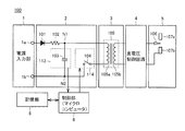
- FIG. It is a figure which shows the structure of the ion generator 100 of Embodiment 1.
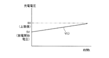
- FIG. It is a figure which shows the relationship between the charging voltage to the capacitor
- FIG. It is a figure which shows the structure of the ion generator 200 of Embodiment 2.
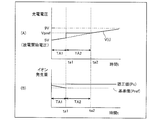
- FIG. It is a figure for demonstrating the relationship between the charging voltage to the capacitor
- FIG. 1 is a diagram illustrating a configuration of an ion generator 100 according to the first embodiment.
- ion generator 100 generates a high voltage generated by power input unit 1, step-up transformer drive circuit 2 connected to power input unit 1, step-up transformer circuit 3, and step-up transformer circuit 3.
- a high voltage control circuit 4 to be controlled, an ion generation unit 5 that generates ions using a corona discharge phenomenon, a control unit 6 that controls the step-up transformer drive circuit 2, and a storage unit 8 are included.
- the control unit 6 for example, a microcomputer is preferable.
- the step-up transformer drive circuit 2 includes a rectifier diode 101, an input resistance element 102, a charging circuit 113 that charges a charge applied to the step-up transformer circuit 3, and a switching unit 114 that switches connection between the step-up transformer circuit 3.
- the charging circuit 113 and the switching unit 114 are controlled by the control unit 6.
- the charging circuit 113 includes a capacitor 103, and the switching unit 114 includes a transformer driving switching element 104.
- the transformer driving switching element 104 can be realized by, for example, a triac or a two-terminal thyristor capable of bidirectional conduction.
- the power input unit 1 includes a terminal 1a and a terminal 1b, and the terminals 1a and 1b are electrically connected to nodes N1 and N2 of the step-up transformer driving circuit 2, respectively.
- the rectifier diode 101 and the input resistance element 102 are connected in series between the terminal 1a and the node N1.
- Capacitor 103 is connected between nodes N1 and N2.
- the primary winding 105a of the step-up transformer circuit 3 and the transformer driving switching element 104 are connected in parallel with the capacitor 103.
- Step-up transformer circuit 3 includes a primary winding 105a and a secondary winding 105b.
- the voltage applied from the power supply input unit 1 is boosted to a high voltage via the secondary winding 105b.
- the boosted voltage is controlled by the high voltage control circuit 4.
- the ion generator 5 includes a discharge electrode needle 106 that receives the boosted voltage from the high voltage control circuit 4 and dielectric electrodes 107 a and 107 b to which a high voltage is applied between the discharge electrode needle 106.
- the storage unit 8 stores in advance, for example, an increase amount of the charging voltage per unit time. These values are read by the control unit 6, and the control unit 6 can control the charging circuit 113 and the switching unit 114, and the ion generation unit 5 can control the amount of ions generated.
- the operation of the ion generator 100 of Embodiment 1 will be described. First, the steps until the high voltage is generated will be described. Specifically, the operation from the power supply input unit 1 to the primary winding 105a of the step-up transformer circuit 3 will be described. The terminal 1a of the power input unit 1 outputs an applied voltage, and the terminal 1b is connected to the ground potential. Charge is charged from the power supply input unit 1 to the capacitor 103 of the charging circuit 113 via the rectifier diode 101 and the input resistance element 102 of the step-up transformer driving circuit 2.
- the transformer driving switching element 104 of the switching unit 114 is opened as shown in FIG. 1, and the electric charge charged in the capacitor 103 of the charging circuit 113 is held.
- the transformer driving switching element 104 is switched from the open state to the closed state by the control unit 6, and the same potential as the potential difference of the capacitor 103 is also applied to the primary winding 105 a of the transformer 105 of the step-up transformer circuit 3.
- the transformer driving switching element 104 is controlled to switch from the closed state to the open state.
- control unit 6 switches the transformer driving switching element 104 of the step-up transformer driving circuit 2 from the open state to the closed state.
- the energy charged in the capacitor 103 is transmitted to the secondary winding 105b of the transformer 105, and a high-voltage potential difference is generated between both ends of the secondary winding 105b.
- the high voltage is applied between the dielectric electrodes 107a and 107b via the high voltage control circuit 4.
- the discharge electrode needle 106 and the dielectric electrodes 107a and 107b only the region where the electric field is strong is locally broken down, and an ionization phenomenon occurs at the pointed tip of the discharge electrode needle 106 to generate ions.
- the control unit 6 can control the level of the high voltage generated at both ends of the secondary winding 105b of the step-up transformer circuit 3 by controlling the potential difference of the capacitor 103 and controlling the open / close state of the transformer driving switching element 104.
- the applied voltage between the discharge electrode needle 106 and the dielectric electrodes 107a and 107b can be controlled.
- FIG. 2 is a diagram showing the relationship between the charging voltage to the capacitor 103 of the ion generator 100 of Embodiment 1 and the usage time.
- the vertical axis indicates the charging voltage (V)
- the horizontal axis indicates the usage time (t).
- the charge voltage shown in FIG. 2 is a function of the usage time t (for example, a linear function). ) ⁇ (use time t).
- V (t) 5 + K ⁇ t (formula 1) when the discharge start voltage is 5 (V).
- the charging voltage increases at a constant rate according to (Equation 1) to prevent aging degradation.
- the discharge start voltage and the coefficient K are stored in the storage unit 8 in advance.
- the controller 6 reads the discharge start voltage and the coefficient K from the storage unit 8.
- the capacitor 103 of the charging circuit 113 is applied with a discharge start voltage (5 V), and ions start to be generated by corona discharge at the tip of the discharge electrode needle 106 of the ion generator 5.
- the charging voltage continues to increase at a constant rate (K), and it is possible to prevent a decrease in the amount of ions due to deterioration over time.
- the storage unit 8 is used to increase the charging voltage according to the usage time. However, the storage unit 8 is not used, and the control unit 6 detects the aging deterioration state of the ion generation unit 5. However, the charging voltage can be increased according to the state.
- the amount of increase in the discharge start voltage and the charge voltage stored in advance in the storage unit 8 is maintained by maintaining the needle tip of the discharge electrode without any deposit or a small amount from the beginning of use.
- the relationship between the charging voltage and the usage time is defined as a linear function, but the present invention is not limited to this.
- FIG. 3 is a diagram illustrating a configuration of the ion generator 200 according to the second embodiment.
- ion generation apparatus 200 includes control unit 6 of ion generation apparatus 100, charging circuit 113 controlled by control unit 6, and switching unit. 114, the capacitor 103 included in the charging circuit 113, the transformer driving switching element 104 included in the switching unit 114, and the storage unit 8, instead of the control unit 6A and the charging circuit 213 controlled by the control unit 6A, and A switching unit 214, a capacitor 203 included in the charging circuit 213, a transformer driving switching element 204 included in the switching unit 214, an ion generation amount detection circuit 207 that detects an ion generation amount generated in the ion generation unit 5, And a storage unit 8A.
- the charging voltage applied to the capacitor 103 is actually increased by the control unit 6 according to the usage time regardless of the amount of ions generated.
- the ion generation amount generated by the ion generation amount detection circuit 207 is detected, and the ion generation amount is transmitted to the control unit 6A.
- the control unit 6A compares the reference ion generation amount (reference value) stored in advance in the storage unit 8A with the ion generation amount detected by the ion generation amount detection circuit 207, and does not satisfy the reference ion generation amount
- the control unit 6A controls the transformer driving switching element 204 of the charging circuit 214 to apply a charging voltage to the capacitor 203 so as to generate an appropriate ion amount Pc (appropriate value) or more.
- the appropriate ion amount Pc or more can be maintained based on the ion generation amount of the actual ion generation amount detection circuit 207.
- FIG. 4 is a diagram for explaining the relationship between the charging voltage to the capacitor 203 and the ion generation amount detected by the ion generation amount detection circuit 207 of the ion generation apparatus 200 of Embodiment 2 and the usage time.
- the waveform of FIG. 4A shows the relationship between the charging voltage of capacitor 203 and the usage time.
- the vertical axis represents the charging voltage (V), and the horizontal axis represents the usage time (t).
- the waveform of FIG. 4B shows the relationship between the ion generation amount detected by the ion generation amount detection circuit 207 corresponding to the charging voltage of the waveform of FIG. 4A and the usage time (t).
- the vertical axis represents the amount of ion generation (P), and the horizontal axis represents the usage time (t).
- the charging voltage V (t) increases with the increase amount K of the charging voltage per unit time as described in FIG.
- the ion generation amount continues to decrease at a constant rate and reaches the reference ion generation amount Pref at time ta1.
- the ion generation amount is larger than the reference ion generation amount Pref stored in the storage unit 8A, and thus the charging voltage is not increased.
- the control unit 6A determines that the ion generation amount is equal to the reference ion generation amount Pref stored in the storage unit 8A, and controls the transformer driving switching element 204 to generate the appropriate ion amount Pc. Vpref is applied to the capacitor 203. Thereby, the ion generation amount detected by the ion generation amount detection circuit 207 increases to the appropriate ion amount Pc.
- the amount of ions to be generated does not have to be the appropriate ion amount Pc, but may be more than the appropriate ion amount Pc.
- control unit 6A applies the voltage Vpref (a constant value) to the capacitor 203 until the time when the charging voltage V (t) and the voltage Vpref are equal (time ta2). After time ta2, control unit 6A causes capacitor 203 to apply a voltage of charging voltage V (t).
- time ta1 After time ta1, it is possible to prevent a decrease in the amount of ion generation and a decrease in the amount of ion generation due to deterioration over time, and the ion generation amount can be maintained at an appropriate ion amount Pc or more.
- control unit 6A applies the voltage based on the actual ion generation amount detected by the ion generation amount detection circuit 207 and the reference ion generation amount stored in the storage unit 8A.
- the ion generation amount is maintained to be equal to or more than the appropriate ion amount Pc.
- a reduction in power consumption can be expected by effectively controlling the charging voltage.
- FIG. 5 is a diagram illustrating another example for explaining the relationship between the charging voltage to the capacitor 203 of the ion generating apparatus 200 of Embodiment 2 and the ion generation amount of the ion generation amount detection circuit 207 and the usage time.
- the waveform of FIG. 5A shows the relationship between the charging voltage of capacitor 203 and the usage time.
- the vertical axis represents the charging voltage (V), and the horizontal axis represents the usage time (t).
- the waveform in FIG. 5B shows the relationship between the ion generation amount corresponding to the charging voltage in the waveform in FIG. 5A and the usage time (t).
- the vertical axis represents the amount of ion generation (P), and the horizontal axis represents the usage time (t).
- the reference ion generation amount is compared with the actual ion generation amount, and when the reference ion generation amount is not satisfied, a charging voltage for generating an appropriate ion amount Pc or more is applied to the capacitor 203. Apply.
- the ion generator 200 has an ion generation amount between the upper limit reference ion generation amount (hereinafter referred to as the upper limit reference value PA) and the lower limit reference ion generation amount (hereinafter referred to as the lower limit reference value PB) (allowable range). ) Can be controlled.
- the upper limit reference value PA the lower limit reference value PB, and coefficients K1, K2, and K3 (K1 ⁇ K2 ⁇ K3) indicating the amount of increase in voltage per unit time in order to prevent a decrease in the generation of ions due to aging. Is stored in advance in the storage unit 8A of FIG.
- the charging voltage can be expressed as a linear function of the usage time t, and the charging voltages are expressed as V1 (t) to V3 (t) for the times TB1 to TB3, respectively.
- K1 is a coefficient indicating the amount of increase in voltage per unit time.
- the discharge start voltage is 5V.
- the charging voltage increases at a constant rate according to (Equation 2) in order to prevent aged deterioration.
- the ion generation amount detected by the ion generation amount detection circuit 207 continues to decrease at a constant rate and reaches the lower limit reference value PB at time tb1. However, until time tb1, the amount of generated ions is larger than the lower limit reference value PB stored in the storage unit 8A, so the charging voltage is not increased.
- the control unit 6A determines that the ion generation amount is equal to the lower limit reference value PB stored in the storage unit 8A, and controls the transformer driving switching element 204 to increase the ion generation amount.
- the voltage value (Vpref1) of the charging voltage for generating the appropriate ion amount Pc stored in advance in the storage unit 8A is applied to the capacitor 203. Thereby, the ion generation amount detected by the ion generation amount detection circuit 207 increases to the appropriate ion amount Pc.
- the amount of ions to be generated does not have to be the appropriate ion amount Pc, but may be more than the appropriate ion amount Pc.
- the amount of generated ions decreases to the lower limit reference value PB at time tb1, although the charging voltage is increased according to the usage time in order to prevent deterioration over time.
- control unit 6A can prevent a decrease in the amount of generated ions by using K3, which is larger than the voltage increase amount K1 per unit time, after time tb1. That is, even when used in an environment deviating from the initial assumption, the control unit 6A can appropriately control the charging voltage so as to reduce the ion generation amount.
- the charging voltage increases at a constant rate according to (Equation 3) in order to prevent aged deterioration.
- the appropriate ion amount Pc at the time tb1 continues to increase at a constant rate, and reaches the upper limit reference value PA at the time tb2. However, until time tb2, the amount of generated ions is smaller than the upper limit reference value PA stored in the storage unit 8A, so the charging voltage is not reduced.
- the control unit 6A determines that the ion generation amount is equal to the upper limit reference value PA stored in the storage unit 8A, and controls the transformer driving switching element 204 to reduce the ion generation amount.
- the voltage value (Vpref2) of the charging voltage for generating the appropriate ion amount Pc stored in advance in the storage unit 8A is applied to the capacitor 203. Thereby, the ion generation amount detected by the ion generation amount detection circuit 207 decreases to the appropriate ion amount Pc.
- the ion generation amount increases to the upper limit reference value PA at time tb2, although the charging voltage is increased in accordance with the usage time in order to prevent deterioration over time.
- the amount of ions to be generated does not have to be the appropriate ion amount Pc, but may be more than the appropriate ion amount Pc.
- control unit 6A can prevent an increase in the amount of ion generation by using K2 having a smaller increase amount than the increase amount K3 of the voltage per unit time after time tb2. That is, even when used in an environment deviating from the initial assumption, the control unit 6A can properly control the charging voltage so that the amount of generated ions is not increased.
- the charging voltage rises more than necessary, a large amount of ozone harmful to the human body may be generated, so if the amount of dust is less than the expected amount, the discharge voltage is lowered to an appropriate value. This has a beneficial effect.
- the amount of generated ions can be kept within an allowable range by performing the same control. Further, dust adhering to the discharge electrode needle due to corona discharge can be suppressed, and ion performance can be continuously secured.
- K1 to K3 as the increase amounts
- a plurality of increase amounts K1, K2, K3,... (K1 ⁇ K2 ⁇ K3 ⁇ ...) are stored in the storage unit 8A in advance, so that more appropriate tolerances can be obtained.
- the amount of ion generation can be controlled within a range.
- FIG. 6 is a diagram for explaining an electric device 500 including the ion generator 100 shown in FIG. Referring to FIG. 6, electric device 500 includes ion generator 100 in FIG. 1 and blower fan 501.
- ions generated by the ion generator 5 can be sent out of the main body. And it can inactivate mold and fungi in the air by the action of ions and suppress their growth.
- the electric equipment include an air conditioner, a dehumidifier, a humidifier, an air purifier, a refrigerator, a fan heater, a microwave oven, a washing / drying machine, a vacuum cleaner, a sterilizer, and a fan.
- the present invention is not limited thereto, and the electrical device may include the ion generator 200 instead of the ion generator 100.
- the ion generator using the discharge electrode needle is used when the first to third embodiments are described with reference to FIGS. 1 to 6, but the present invention is not limited to this.
- the present invention can be similarly applied to an ion generator using creeping discharge.
- the present invention can be similarly applied to an ion generator that does not include a dielectric electrode and discharges ions from the discharge electrode needle into the atmosphere.
Landscapes
- Elimination Of Static Electricity (AREA)
- Disinfection, Sterilisation Or Deodorisation Of Air (AREA)
Abstract
使用時間の経過に伴いイオンの発生のための印加電圧が増加する電圧印加部(2,3)と、印加電圧によりイオンを発生させるイオン発生部(5)とを含む。電圧印加部(2,3)は、印加電圧を生成するための基礎電圧を駆動する昇圧トランス駆動回路(2)と、基礎電圧を印加電圧まで昇圧する昇圧トランス回路(3)とを含み、昇圧トランス駆動回路(2)は、使用時間の経過に伴い基礎電圧を増加させる。これにより、周囲帯電物が針先に付着するのを抑制し、従来の放電電極針と誘導電極間に一定の電圧を印加するイオン発生装置に比べ、イオン性能を継続的に確保できる。
Description
本発明は、イオン発生装置および電気機器に関するものであり、特に、イオンを空気中に発生させるイオン発生装置および電気機器に関する。
放電現象を利用した多くのイオン発生装置が実用化されている。標準的なイオン発生装置は、針電極と対向電極との間、又は放電電極と誘電電極との間に高電圧交流の駆動電圧を印加することにより、コロナ放電を発生させて正及び負のイオンを発生させる。
この方式のイオン発生装置の1つの例として、たとえば特開2010-015943号公報(特許文献1)に開示された装置がある。この特開2010-015943号公報(特許文献1)に開示された装置は、正イオンおよび負イオンの双方を効率よく装置外部へ放出でき、かつ容易に小型化・薄型化を図ることを目的としている。このため、正イオン発生部と、負イオン発生部とを本体内に備え、さらに第1基板と、第2基板と、回路部とを備えている。正イオン発生部は、正極放電電極と、その正極放電電極との間で正イオンを発生させるための第1誘導電極とを含んでいる。負イオン発生部は、負極放電電極と、その負極放電電極との間で負イオンを発生させるための第2誘導電極とを含んでいる。第1基板は、正極放電電極と第1誘導電極との双方を保持している。第2基板は、負極放電電極と第2誘導電極との双方を保持している。第1基板と第2基板とが互いに分離するように、第1誘導電極と第2誘導電極とを離間させて、正イオン発生部と負イオン発生部とが互いに夫々発生する正イオンおよび負イオンで互いに中和しあうことを抑制するためのスペースを挟んで配置されている。回路部は、スペースに配置された部分を有している。
しかしながら、特開2010-015943号公報(特許文献1)に開示されたイオン発生装置では、使用する環境によって、放電電極の針先に、帯電した塵埃などが付着することがある。針先に塵埃が付着して堆積した場合、コロナ放電が発生しにくくなり、イオンの発生量が減少することが避けられない。また、一定の電圧を印加しているイオン発生装置では経年劣化によるイオン発生量の減少を防止できない。
本発明の目的は、上記問題を解決するため、周囲帯電物が針先に付着するのを抑制し、従来の放電電極針と誘導電極間に一定の電圧を印加するイオン発生装置に比べ、イオン性能を継続的に確保できるイオン発生装置およびイオン発生装置を含む電気機器を提供することである。
この発明のある局面に従うと、イオン発生装置であって、使用時間の経過に伴いイオンの発生のための印加電圧が増加する電圧印加部と、印加電圧によりイオンを発生させるイオン発生部とを含む。
好ましくは、電圧印加部は、印加電圧を生成するための基礎電圧を駆動する昇圧トランス駆動回路と、基礎電圧を印加電圧まで昇圧する昇圧トランス回路とを含み、昇圧トランス駆動回路は、使用時間の経過に伴い基礎電圧を増加させる。
また好ましくは、使用時間の経過に伴い、基礎電圧が増加するように昇圧トランス駆動回路を制御する制御部をさらに含む。
さらに好ましくは、使用時間と基礎電圧との関係を示すデータを記憶する記憶部をさらに含む、制御部は、記憶部を参照して昇圧トランス駆動回路を制御する。
また好ましくは、イオン発生部は、イオンの発生量を検出するイオン発生量検出部を含み、制御部は、検出されたイオンの発生量が所望量になるように基礎電圧を制御する。
好ましくは、検出されたイオンの発生量を判断するための基準データが記憶される記憶部をさらに含む、制御部は検出されたイオンの発生量が基準データに対応するイオン発生量以下となった場合に、基礎電圧を増加させる。
この発明は、他の局面に従うと、電気機器であって、使用時間の経過に伴いイオンの発生のための印加電圧が増加する電圧印加部と、印加電圧によりイオンを発生させるイオン発生部と、イオンを空気中に送出する送出部とを含む。
好ましくは、電圧印加部は、印加電圧を生成するための基礎電圧を駆動する昇圧トランス駆動回路と、基礎電圧を印加電圧まで昇圧する昇圧トランス回路とを含み、昇圧トランス駆動回路は、使用時間の経過に伴い基礎電圧を増加させる。
また好ましくは、使用時間の経過に伴い、基礎電圧が増加するように昇圧トランス駆動回路を制御する制御部をさらに含む。
さらに好ましくは、使用時間と基礎電圧との関係を示すデータを記憶する記憶部をさらに含む、制御部は、記憶部を参照して昇圧トランス駆動回路を制御する。
また好ましくは、イオン発生部は、イオンの発生量を検出するイオン発生量検出部を含み、制御部は、検出されたイオンの発生量が所望量になるように基礎電圧を制御する。
好ましくは、検出されたイオンの発生量を判断するための基準データが記憶される記憶部をさらに含む、制御部は検出されたイオンの発生量が基準データに対応するイオン発生量以下となった場合に、基礎電圧を増加させる。
従って、本発明の主たる利点は、放電電極針と誘導電極間との印加電圧を時間の経過に合わせ印加電圧を上げることにより、コロナ放電により放電電極針に付着する塵埃を抑制することができ、イオン性能を継続的に確保できるイオン発生装置およびイオン発生装置を含む電気機器を提供することができる点である。
以下、本発明について図面を参照して詳しく説明する。なお、図中同一又は相当部分には同一の符号を付してその説明は繰り返さない。
[実施の形態1]
図1は、実施の形態1のイオン発生装置100の構成を示す図である。図1を参照して、イオン発生装置100は、電源入力部1と、電源入力部1に接続される昇圧トランス駆動回路2と、昇圧トランス回路3と、昇圧トランス回路3によって発生した高電圧を制御する高電圧制御回路4と、コロナ放電現象を利用してイオンを発生するイオン発生部5と、昇圧トランス駆動回路2を制御する制御部6と、記憶部8とを含む。制御部6として、たとえばマイクロコンピュータが好ましい。
図1は、実施の形態1のイオン発生装置100の構成を示す図である。図1を参照して、イオン発生装置100は、電源入力部1と、電源入力部1に接続される昇圧トランス駆動回路2と、昇圧トランス回路3と、昇圧トランス回路3によって発生した高電圧を制御する高電圧制御回路4と、コロナ放電現象を利用してイオンを発生するイオン発生部5と、昇圧トランス駆動回路2を制御する制御部6と、記憶部8とを含む。制御部6として、たとえばマイクロコンピュータが好ましい。
昇圧トランス駆動回路2は、整流ダイオード101と、入力抵抗素子102と、昇圧トランス回路3に印加する電荷を充電する充電回路113と、昇圧トランス回路3との接続を切り替える切替部114とを含む。この充電回路113および切替部114は、制御部6によって制御される。
充電回路113はコンデンサ103を含み、切替部114はトランス駆動用スイッチング素子104を含む。トランス駆動用スイッチング素子104は、たとえば双方向導通可能となるトライアックや2端子サイリスタなどで実現できる。
電源入力部1は、端子1aと端子1bを含み、端子1a、1bは、昇圧トランス駆動回路2のノードN1、N2にそれぞれ電気的に接続される。
整流ダイオード101および入力抵抗素子102は、端子1aとノードN1との間に直列に接続される。また、コンデンサ103は、ノードN1とノードN2との間に接続される。
コンデンサ103と並列に昇圧トランス回路3の1次巻線105aおよびトランス駆動用スイッチング素子104が接続される。
昇圧トランス回路3は、1次巻線105aと、2次巻線105bとを含む。電源入力部1から印加された電圧は、2次巻線105bを介して、高電圧に昇圧される。この昇圧された電圧は高電圧制御回路4によって制御される。
イオン発生部5は、高電圧制御回路4からの昇圧電圧を受ける放電電極針106と、放電電極針106との間に高電圧が印加される誘電電極107a、107bとを含む。
記憶部8は、たとえば、単位時間当たりの充電電圧の増加量を予め格納する。これらの値が制御部6に読み込まれ、制御部6は、充電回路113や切替部114を制御し、イオン発生部5においてイオンの発生量を制御できる。
次に、実施の形態1のイオン発生装置100の動作について説明する。
最初に、高電圧が生じる前までの段階について説明する。具体的には、電源入力部1から昇圧トランス回路3の1次巻線105aまでの動作について説明する。電源入力部1の端子1aは印加電圧を出力し、端子1bは接地電位に接続されている。電源入力部1から昇圧トランス駆動回路2の整流ダイオード101および入力抵抗素子102を介して、充電回路113のコンデンサ103に電荷が充電される。
最初に、高電圧が生じる前までの段階について説明する。具体的には、電源入力部1から昇圧トランス回路3の1次巻線105aまでの動作について説明する。電源入力部1の端子1aは印加電圧を出力し、端子1bは接地電位に接続されている。電源入力部1から昇圧トランス駆動回路2の整流ダイオード101および入力抵抗素子102を介して、充電回路113のコンデンサ103に電荷が充電される。
なお、このとき切替部114のトランス駆動用スイッチング素子104は、図1のように開状態とし、充電回路113のコンデンサ103に充電された電荷は保持されたままである。
その後、トランス駆動用スイッチング素子104が制御部6によって開状態から閉状態に切り替わり、昇圧トランス回路3のトランス105の1次巻線105aにおいてもコンデンサ103の電位差と同じ電位が印加される。
この電圧印加直後、コンデンサ103に蓄えられていた電荷は、トランス105の1次巻線105aを通じて放電される(放電動作)。放電された結果、コンデンサ103の電荷がなくなり、電位差が0(V)となる。
制御部6は、コンデンサ103の電位差レベルを制御し、電位差が0(V)と判定すると、トランス駆動用スイッチング素子104を制御され閉状態から開状態へ切り替える。
再び、電源入力部1から入力電圧が印加され、コンデンサ103へ電荷が蓄えられる充電動作が開始される。この充電動作と放電動作とが規定周期で繰り返される。
続いて、高電圧の発生後イオン発生までの段階について説明する。具体的には、昇圧トランス回路3のトランス105の2次巻線105b側以降の回路について説明する。
まず制御部6によって、昇圧トランス駆動回路2のトランス駆動用スイッチング素子104は開状態から閉状態へ切り替わる。
コンデンサ103に充電されたエネルギーがトランス105の2次巻線105bに伝達され、2次巻線105bの両端に高電圧の電位差が生じる。
この高電圧が高電圧制御回路4を介し、誘電電極107a、107bとの間に高電圧が印加される。放電電極針106と誘電電極107a、107bとの間において、電界の強い領域だけが局所的に絶縁破壊され、放電電極針106の尖った先端部で電離現象が起こり、イオンが発生する。
制御部6は、コンデンサ103の電位差を制御し、トランス駆動用スイッチング素子104の開閉状態を制御することで、昇圧トランス回路3の2次巻線105bの両端に発生する高電圧のレベルを制御でき、放電電極針106と誘電電極107a、107bとの間の印加電圧を制御できる。
図2は、実施の形態1のイオン発生装置100のコンデンサ103への充電電圧と使用時間との関係を示す図である。図2を参照して、縦軸に充電電圧(V)が示され、横軸に使用時間(t)が示される。
図2で示されている充電電圧が使用時間tの関数(たとえば、一次関数)として、充電電圧V(t)=(放電開始電圧)+(単位時間当たりの充電電圧の増加量を示す係数K)×(使用時間t)と表される。
そうすると、図2に示される充電電圧V(t)は、放電開始電圧を5(V)とすると、V(t)=5+K×t(式1)と表される。
使用時間に応じて、経年劣化防止のため、充電電圧は(式1)に従い一定の割合で増加する。なお、放電開始電圧および係数Kは、予め記憶部8に格納される。制御部6によって放電開始電圧および係数Kが記憶部8から読み込まれる。
時刻0において、充電回路113のコンデンサ103は、放電開始電圧(5V)を印加され、イオン発生部5の放電電極針106の先端においてコロナ放電によりイオンが発生し始める。
これにより、周囲帯電物の放電電極の針先への付着を抑制し、使用開始当初の放電電極の針先に付着物のないあるいは少量の状態を維持することができる。
その後使用時間が増加するにつれて、充電電圧は一定の割合(K)で増加し続け、経年劣化によるイオン量の減少を防止できる。
なお、上記の説明では、使用時間とともに増加し続けるが、これに限らず、充電電圧の最大値を9Vと設定し、充電電圧が9Vに達した場合には、その後は一定値(9V)が維持されるということもできる。
また、実施の形態1では、記憶部8を用いて、使用時間に応じて充電電圧を増加させたが、記憶部8を用いず、イオン発生部5の経年劣化の状態を制御部6が検出し、その状態に応じて充電電圧を増加させることもできる。
以上図2を用いて説明したように、使用開始当初から放電電極の針先に付着物のないあるいは少量の状態を維持させ、予め記憶部8に格納された放電開始電圧や充電電圧の増加量を示す係数を用いて、充電電圧を使用時間に応じて増加させることにより、経年劣化のイオン量の減少の防止し、一定のイオン量を発生させることができる。
なお、上記の説明では、充電電圧と使用時間との関係を一次関数として規定したが、これに限られるものではない。
[実施の形態2]
実施の形態1のイオン発生装置100との比較のために、実施の形態2のイオン発生装置200について説明する。図3は、実施の形態2のイオン発生装置200の構成を示す図である。
実施の形態1のイオン発生装置100との比較のために、実施の形態2のイオン発生装置200について説明する。図3は、実施の形態2のイオン発生装置200の構成を示す図である。
図3を参照して、このイオン発生装置200は、図1のイオン発生装置100の構成に加えて、イオン発生装置100の制御部6と、制御部6に制御される充電回路113および切替部114と、充電回路113に含まれるコンデンサ103と、切替部114に含まれるトランス駆動用スイッチング素子104と、記憶部8とに代えて、制御部6Aと制御部6Aに制御される充電回路213および切替部214と、充電回路213に含まれるコンデンサ203と、切替部214に含まれるトランス駆動用スイッチング素子204と、イオン発生部5において発生したイオン発生量を検知するイオン発生量検知回路207と、記憶部8Aとをさらに含む。
実施の形態1では、コンデンサ103に印加される充電電圧について実際にイオン発生量とは関係なく、制御部6によって充電電圧が使用時間に応じて増加される。
一方、実施の形態2では、イオン発生量検知回路207が発生したイオン発生量を検知し、そのイオン発生量を制御部6Aに送信する。制御部6Aは、記憶部8Aに予め格納されている基準イオン発生量(基準値)とイオン発生量検知回路207によって検知されたイオン発生量とを比較し、基準イオン発生量を満たしていない場合には、制御部6Aは、充電回路214のトランス駆動用スイッチング素子204を制御し、適正イオン量Pc(適正値)以上を発生させる充電電圧をコンデンサ203に印加させる。
これにより、周囲帯電物の放電電極の針先への付着を抑制し、使用開始当初の放電電極の針先に付着物のないあるいは少量の状態を維持することができる。また、経年劣化によるイオン発生量の減少を防止のために、実際のイオン発生量検知回路207のイオン発生量に基づき、適正イオン量Pc以上を維持することができる。
図4は、実施の形態2のイオン発生装置200のコンデンサ203への充電電圧およびイオン発生量検知回路207によって検知されたイオン発生量と使用時間との関係を説明するための図である。
図4を参照して、図4(A)の波形には、コンデンサ203の充電電圧と使用時間との関係が示される。縦軸に充電電圧(V)が示され、横軸に使用時間(t)が示される。図4(B)の波形には、図4(A)の波形の充電電圧に対応したイオン発生量検知回路207によって検知されたイオン発生量と使用時間(t)との関係が示される。縦軸にイオン発生量(P)が示され、横軸に使用時間(t)が示される。
時間TA1(時刻0~ta1)において、充電電圧V(t)は、図2で説明したのと同様に単位時間当たりの充電電圧の増加量Kで増加する。一方、イオン発生量は、一定の割合で減少し続け時刻ta1で基準イオン発生量Prefに至る。しかしながら、時刻ta1に至るまでは、イオン発生量は、記憶部8Aに格納されている基準イオン発生量Prefより多いため、充電電圧を増加することはない。
時刻ta1において、制御部6Aは、イオン発生量が記憶部8Aに格納されている基準イオン発生量Prefと等しいと判断し、トランス駆動用スイッチング素子204を制御し、適正イオン量Pcを発生させる電圧Vprefをコンデンサ203に印加させる。これにより、イオン発生量検知回路207によって検知されるイオン発生量は、適正イオン量Pcまで増加する。
なお、発生させるイオン量は、適正イオン量Pcである必要はなく、適正イオン量Pc以上であればよい。
その後、制御部6Aは、充電電圧V(t)と電圧Vprefとが等しい時刻(時刻ta2)まで、コンデンサ203に電圧Vpref(一定値)が印加される。時刻ta2以降は、制御部6Aは、コンデンサ203に充電電圧V(t)の電圧を印加させる。
時刻ta1以後は、イオン発生量の減少と経年劣化によるイオン量発生の減少を防止し、イオン発生量は、適正イオン量Pc以上を維持できる。
以上図4を用いて説明したように、イオン発生量検知回路207によって検知される実際のイオン発生量と記憶部8Aに格納されている基準イオン発生量とに基づき、制御部6Aは、印加する充電電圧を制御することで、イオン発生量は適正イオン量Pc以上となるように維持される。また、効果的に充電電圧を制御することにより、消費電力の減少も見込める。
図5は、実施の形態2のイオン発生装置200のコンデンサ203への充電電圧およびイオン発生量検知回路207のイオン発生量と使用時間との関係を説明するための別の一例の図である。
図5を参照して、図5(A)の波形には、コンデンサ203の充電電圧と使用時間との関係が示される。縦軸に充電電圧(V)が示され、横軸に使用時間(t)が示される。図5(B)の波形には、図5(A)の波形の充電電圧に対応したイオン発生量と使用時間(t)との関係が示される。縦軸にイオン発生量(P)が示され、横軸に使用時間(t)が示される。
上記図4で説明した例では、基準イオン発生量と実際のイオン発生量とを比較し、基準イオン発生量を満たしていない場合には、適正イオン量Pc以上を発生させる充電電圧をコンデンサ203に印加させる。
一方、上記に加えイオン発生装置200は、イオン発生量を上限基準イオン発生量(以下、上限基準値PAという)と下限基準イオン発生量(以下、下限基準値PBという)との間(許容範囲)に制御できる。
ここで、上限基準値PAと、下限基準値PBと、経年劣化のイオン発生の減少を防止するため単位時間あたりの電圧の増加量を示す係数K1、K2、K3(K1<K2<K3)とは図3の記憶部8Aに予め格納されている。
図2で説明したのと同様に、充電電圧は使用時間tの一次関数として表すことができ、時間TB1~TB3について充電電圧はそれぞれV1(t)~V3(t)と表される。
時間TB1(時刻0~時刻tb1)において、充電電圧V1(t)は、V1(t)=5+K1×t(式2)と表される。ここで、K1は単位時間あたりの電圧の増加量を示す係数である。また、放電開始電圧は5Vとする。使用時間に応じて、経年劣化防止のため、充電電圧は(式2)に従い一定の割合で増加する。
一方、イオン発生量検知回路207によって検知されるイオン発生量は、一定の割合で減少し続け時刻tb1で下限基準値PBに至る。しかしながら、時刻tb1に至るまでは、イオン発生量は記憶部8Aに格納されている下限基準値PBより多いため、充電電圧は増加されない。
時刻tb1において、制御部6Aは、イオン発生量が記憶部8Aに格納されている下限基準値PBと等しいと判断し、イオン発生量を増加させるために、トランス駆動用スイッチング素子204を制御し、記憶部8Aに予め格納された適正イオン量Pcを発生させるための充電電圧の電圧値(Vpref1)をコンデンサ203に印加させる。これにより、イオン発生量検知回路207によって検知されるイオン発生量は、適正イオン量Pcまで増加する。
なお、発生させるイオン量は、適正イオン量Pcである必要はなく、適正イオン量Pc以上であればよい。
さらに、時間TB1では、経年劣化を防止するために充電電圧は使用時間に応じて増加させているにも関わらず、時刻tb1においてイオン発生量が下限基準値PBまで減少している。
これは、放電電極針106に付着した塵埃の量が想定していた経年劣化による塵埃の量に比べて多く、イオン発生量が減少し、また、イオン発生装置の使用環境についても、想定している環境と比較すると、塵埃が付着しやすい環境での使用であることが考えられる。
したがって、制御部6Aは、単位時間あたりの電圧の増加量K1より増加量が大きいK3を時刻tb1以後使用することで、イオン発生量の減少を防止することができる。すなわち、当初の想定から外れた環境で使用されている場合でも、制御部6Aによって充電電圧が適正に制御され、イオン発生量を減少させるように制御できる。
次に、時間TB2(時刻tb1~tb2)において、充電電圧V2(t)は、上記のK3を用いてV2(t)=Vpref1+K3×(t-tb1)(式3)と表される。使用時間に応じて、経年劣化防止のため、充電電圧は(式3)に従い一定の割合で増加する。
一方、イオン発生量検知回路207によって検知されるイオン発生量は、時刻tb1での適正イオン量Pcは、一定の割合で増加し続け、時刻tb2で上限基準値PAに至る。しかしながら、時刻tb2に至るまでは、イオン発生量は記憶部8Aに格納されている上限基準値PAより少ないため、充電電圧は減少されない。
時刻tb2において、制御部6Aは、イオン発生量が記憶部8Aに格納されている上限基準値PAと等しいと判断し、イオン発生量を減少させるために、トランス駆動用スイッチング素子204を制御し、記憶部8Aに予め格納された適正イオン量Pcを発生させるための充電電圧の電圧値(Vpref2)がコンデンサ203に印加される。これにより、イオン発生量検知回路207によって検知されるイオン発生量は、適正イオン量Pcまで減少する。
さらに、時間TB2では、経年劣化を防止するために充電電圧は使用時間に応じて増加させているにも関わらず、時刻tb2においてイオン発生量が上限基準値PAまで増加している。
なお、発生させるイオン量は、適正イオン量Pcである必要はなく、適正イオン量Pc以上であればよい。
これは、放電電極針106に付着した塵埃の量が想定していた経年劣化による塵埃の量に比べて少なく、イオン発生量が増加し、また、イオン発生装置の使用環境についても、想定している環境と比較すると、塵埃が付着しにくい環境での使用であることが考えられる。
したがって、制御部6Aは、単位時間あたりの電圧の増加量K3より増加量が少ないK2を時刻tb2以後使用することで、イオン発生量の増加を防止することができる。すなわち、当初の想定から外れた環境で使用されている場合でも、制御部6Aによって充電電圧が適正に制御され、イオン発生量を増加させないように制御できる。
なお、充電電圧が必要以上に上昇してしまうと、人体に有害であるオゾンが大量に発生してしまうことがあるため、塵埃が想定量より少ない場合に、放電電圧を下げて適正値にすることは有益な効果をもたらすものである。
時刻tb2以後は、同様な制御をすることでイオン発生量を許容範囲内に収めることができる。また、コロナ放電により放電電極針に付着する塵埃を抑制することができ、イオン性能を継続的に確保できる。
また、増加量としてK1~K3を用いて説明したが、複数の増加量K1、K2,K3、…(K1<K2<K3<…)を予め記憶部8Aに格納することにより、さらに適切な許容範囲にイオン発生量を制御することができる。
以上図1~図5を用いて説明したように、放電電極針と誘電電極間の印加電圧を時間の経過に合わせ印加電圧を上げることにより、コロナ放電により放電電極針に付着する塵埃を抑制することができ、イオン性能を継続的に確保できる。
[実施の形態3]
図6は、図1で示したイオン発生装置100を含む電気機器500を説明するための図である。図6を参照して、電気機器500は、図1のイオン発生装置100と、送風ファン501とを含む。
図6は、図1で示したイオン発生装置100を含む電気機器500を説明するための図である。図6を参照して、電気機器500は、図1のイオン発生装置100と、送風ファン501とを含む。
電気機器500が送風ファン501を駆動することにより、イオン発生部5で発生したイオンを本体外に送り出すことができる。そして、イオンの作用により空気中のカビや菌を不活性化させ、それらの増殖を抑制することができる。電気機器としては、たとえば、空気調和機、除湿器、加湿器、空気清浄機、冷蔵庫、ファンヒータ、電子レンジ、洗濯乾燥機、掃除機、殺菌装置、扇風機がある。
ここでは、イオン発生装置100について説明したが、これに限らず、電気機器は、イオン発生装置100に代えて、イオン発生装置200を含むこともできる。
以上図1~図6を用いて実施の形態1~3を説明する際に放電電極針を用いたイオン発生装置を用いたがこれに限定されない。たとえば沿面放電によるイオン発生装置についても同様に適用できる。さらに、誘電電極を含まず、放電電極針から大気中にイオンが放電されるイオン発生装置についても同様に適用できる。
今回開示された実施の形態はすべての点で例示であって制限的なものではないと考えられるべきである。本発明の範囲は上記した説明ではなくて請求の範囲によって示され、請求の範囲と均等の意味および範囲内でのすべての変更が含まれることが意図される。
1 電源入力部、1a,1b 端子、2 昇圧トランス駆動回路、3 昇圧トランス回路、4 高電圧制御回路、5 イオン発生部、6,6A 制御部、8,8A 記憶部、100,200 イオン発生装置、101 整流ダイオード、102 入力抵抗素子、103,203 コンデンサ、104,204 トランス駆動用スイッチング素子、105 トランス、106 放電電極針、107a,107b 誘電電極、113,213 充電回路、114,214 切替部、207 イオン発生量検知回路、500 電気機器、501 送風ファン。
Claims (12)
- 使用時間の経過に伴いイオンの発生のための印加電圧が増加する電圧印加部(2,3)と、
前記印加電圧により前記イオンを発生させるイオン発生部(5)とを備えるイオン発生装置。 - 前記電圧印加部(2,3)は、
前記印加電圧を生成するための基礎電圧を駆動する昇圧トランス駆動回路(2)と、
前記基礎電圧を前記印加電圧まで昇圧する昇圧トランス回路(3)とを含み、
前記昇圧トランス駆動回路(2)は、前記使用時間の経過に伴い前記基礎電圧を増加させる、請求項1に記載のイオン発生装置。 - 前記使用時間の経過に伴い、前記基礎電圧が増加するように前記昇圧トランス駆動回路(2)を制御する制御部(6;6A)をさらに備える、請求項2に記載のイオン発生装置。
- 前記使用時間と前記基礎電圧との関係を示すデータを記憶する記憶部(8)をさらに備え、
前記制御部(6)は、前記記憶部(8)を参照して前記昇圧トランス駆動回路(2)を制御する、請求項3に記載のイオン発生装置。 - 前記イオン発生部(5)は、前記イオンの発生量を検出するイオン発生量検出部(207)を含み、
前記制御部(6A)は、前記検出された前記イオンの発生量が所望量になるように前記基礎電圧を制御する、請求項3に記載のイオン発生装置。 - 前記検出された前記イオンの発生量を判断するための基準データが記憶される記憶部(8A)をさらに備え、
前記制御部(6A)は前記検出された前記イオンの発生量が前記基準データに対応するイオン発生量以下となった場合に、前記基礎電圧を増加させる、請求項5に記載のイオン発生装置。 - 使用時間の経過に伴いイオンの発生のための印加電圧が増加する電圧印加部(2,3)と、
前記印加電圧により前記イオンを発生させるイオン発生部(5)と、
前記イオンを空気中に送出する送出部(501)とを備える電気機器。 - 前記電圧印加部(2,3)は、
前記印加電圧を生成するための基礎電圧を駆動する昇圧トランス駆動回路(2)と、
前記基礎電圧を前記印加電圧まで昇圧する昇圧トランス回路(3)とを含み、
前記昇圧トランス駆動回路(2)は、前記使用時間の経過に伴い前記基礎電圧を増加させる、請求項7に記載の電気機器。 - 前記使用時間の経過に伴い、前記基礎電圧が増加するように前記昇圧トランス駆動回路(2)を制御する制御部(6;6A)をさらに備える、請求項8に記載の電気機器。
- 前記使用時間と前記基礎電圧との関係を示すデータを記憶する記憶部(8)をさらに備え、
前記制御部(6)は、前記記憶部(8)を参照して前記昇圧トランス駆動回路(2)を制御する、請求項9に記載の電気機器。 - 前記イオン発生部(5)は、前記イオンの発生量を検出するイオン発生量検出部(207)を含み、
前記制御部(6A)は、前記検出された前記イオンの発生量が所望量になるように前記基礎電圧を制御する、請求項9に記載の電気機器。 - 前記検出された前記イオンの発生量を判断するための基準データが記憶される記憶部(8A)をさらに備え、
前記制御部(6A)は前記検出された前記イオンの発生量が前記基準データに対応するイオン発生量以下となった場合に、前記基礎電圧を増加させる、請求項11に記載の電気機器。
Applications Claiming Priority (2)
| Application Number | Priority Date | Filing Date | Title |
|---|---|---|---|
| JP2011-119070 | 2011-05-27 | ||
| JP2011119070A JP5175373B2 (ja) | 2011-05-27 | 2011-05-27 | イオン発生装置および電気機器 |
Publications (1)
| Publication Number | Publication Date |
|---|---|
| WO2012165114A1 true WO2012165114A1 (ja) | 2012-12-06 |
Family
ID=47258978
Family Applications (1)
| Application Number | Title | Priority Date | Filing Date |
|---|---|---|---|
| PCT/JP2012/061970 Ceased WO2012165114A1 (ja) | 2011-05-27 | 2012-05-10 | イオン発生装置および電気機器 |
Country Status (2)
| Country | Link |
|---|---|
| JP (1) | JP5175373B2 (ja) |
| WO (1) | WO2012165114A1 (ja) |
Cited By (2)
| Publication number | Priority date | Publication date | Assignee | Title |
|---|---|---|---|---|
| TWI495401B (zh) * | 2013-06-10 | 2015-08-01 | Yi Jing Technology Co Ltd | 具主動感測回饋之離子產生裝置 |
| EP2846118A4 (en) * | 2013-07-01 | 2016-01-13 | Hisense Ronshen Gd Refrig Co | FRESH HOLDING AND STERILIZATION DEVICE FOR REFRIGERATOR AND CONTROL PROCESS |
Families Citing this family (1)
| Publication number | Priority date | Publication date | Assignee | Title |
|---|---|---|---|---|
| JP6476067B2 (ja) * | 2015-05-26 | 2019-02-27 | シャープ株式会社 | イオン発生装置および電気機器 |
Citations (4)
| Publication number | Priority date | Publication date | Assignee | Title |
|---|---|---|---|---|
| JP2004127858A (ja) * | 2002-07-31 | 2004-04-22 | Sunx Ltd | 除電装置 |
| JP2005332774A (ja) * | 2004-05-21 | 2005-12-02 | Sharp Corp | イオン発生装置及びそれを備えた空気調節装置 |
| JP2009016062A (ja) * | 2007-06-29 | 2009-01-22 | Sunx Ltd | 除電装置 |
| JP2009295546A (ja) * | 2008-06-09 | 2009-12-17 | Sharp Corp | イオン発生装置 |
-
2011
- 2011-05-27 JP JP2011119070A patent/JP5175373B2/ja not_active Expired - Fee Related
-
2012
- 2012-05-10 WO PCT/JP2012/061970 patent/WO2012165114A1/ja not_active Ceased
Patent Citations (4)
| Publication number | Priority date | Publication date | Assignee | Title |
|---|---|---|---|---|
| JP2004127858A (ja) * | 2002-07-31 | 2004-04-22 | Sunx Ltd | 除電装置 |
| JP2005332774A (ja) * | 2004-05-21 | 2005-12-02 | Sharp Corp | イオン発生装置及びそれを備えた空気調節装置 |
| JP2009016062A (ja) * | 2007-06-29 | 2009-01-22 | Sunx Ltd | 除電装置 |
| JP2009295546A (ja) * | 2008-06-09 | 2009-12-17 | Sharp Corp | イオン発生装置 |
Cited By (2)
| Publication number | Priority date | Publication date | Assignee | Title |
|---|---|---|---|---|
| TWI495401B (zh) * | 2013-06-10 | 2015-08-01 | Yi Jing Technology Co Ltd | 具主動感測回饋之離子產生裝置 |
| EP2846118A4 (en) * | 2013-07-01 | 2016-01-13 | Hisense Ronshen Gd Refrig Co | FRESH HOLDING AND STERILIZATION DEVICE FOR REFRIGERATOR AND CONTROL PROCESS |
Also Published As
| Publication number | Publication date |
|---|---|
| JP2012248398A (ja) | 2012-12-13 |
| JP5175373B2 (ja) | 2013-04-03 |
Similar Documents
| Publication | Publication Date | Title |
|---|---|---|
| JP4489090B2 (ja) | イオン発生装置及び電気機器 | |
| JP2009016288A (ja) | 高電圧発生回路、イオン発生装置、および電気機器 | |
| TWI234330B (en) | Li-ion/Li-polymer battery charger configured to be DC-powered from multiple types of wall adapters | |
| EP2039434A1 (en) | Electrostatic atomizer and hot air blower having the same | |
| JP5175373B2 (ja) | イオン発生装置および電気機器 | |
| US9041245B2 (en) | Power supply apparatus and method to control the same | |
| JP5836108B2 (ja) | X線撮影装置 | |
| JP2009021110A (ja) | 高電圧発生回路、イオン発生装置、及び電気機器 | |
| US20060073085A1 (en) | Anion generator | |
| EP3292915B1 (en) | Voltage application device and discharge device | |
| CN103682990B (zh) | 离子发生器 | |
| JP2009193847A (ja) | 電圧印加回路と、それを用いたイオン発生装置および電気機器 | |
| JP4133086B2 (ja) | 除電装置 | |
| JP2007294180A (ja) | イオン発生装置及びこれを備えた電気機器 | |
| JP4127524B2 (ja) | イオン発生装置及びこれを備えた電気機器 | |
| CN1714495A (zh) | 具有延迟补偿电流模式控制的开关模式电源 | |
| JP6476067B2 (ja) | イオン発生装置および電気機器 | |
| CN104066264B (zh) | 一种直流自激脉冲大面积大气压沿面放电发生装置 | |
| JP2005038616A (ja) | イオン発生装置及びこれを備えた電気機器 | |
| JP4646796B2 (ja) | 電圧発生回路及びイオン発生器 | |
| JP4762759B2 (ja) | インパルス状電圧発生回路、イオン発生装置、及び電気機器 | |
| JP2017027848A (ja) | イオン発生装置 | |
| JP2013051183A (ja) | イオン発生装置 | |
| CN119196831A (zh) | 流光杀菌装置及其控制方法、电子设备和存储介质 | |
| US20070139009A1 (en) | Battery charge circuit with multi-charge stage and method thereof |
Legal Events
| Date | Code | Title | Description |
|---|---|---|---|
| 121 | Ep: the epo has been informed by wipo that ep was designated in this application |
Ref document number: 12792396 Country of ref document: EP Kind code of ref document: A1 |
|
| NENP | Non-entry into the national phase |
Ref country code: DE |
|
| 122 | Ep: pct application non-entry in european phase |
Ref document number: 12792396 Country of ref document: EP Kind code of ref document: A1 |