WO2012164602A1 - 放射線撮影装置 - Google Patents
放射線撮影装置 Download PDFInfo
- Publication number
- WO2012164602A1 WO2012164602A1 PCT/JP2011/002980 JP2011002980W WO2012164602A1 WO 2012164602 A1 WO2012164602 A1 WO 2012164602A1 JP 2011002980 W JP2011002980 W JP 2011002980W WO 2012164602 A1 WO2012164602 A1 WO 2012164602A1
- Authority
- WO
- WIPO (PCT)
- Prior art keywords
- proximity sensor
- fpd
- covering member
- approach
- proximity
- Prior art date
- Legal status (The legal status is an assumption and is not a legal conclusion. Google has not performed a legal analysis and makes no representation as to the accuracy of the status listed.)
- Ceased
Links
Images





Classifications
-
- A—HUMAN NECESSITIES
- A61—MEDICAL OR VETERINARY SCIENCE; HYGIENE
- A61B—DIAGNOSIS; SURGERY; IDENTIFICATION
- A61B6/00—Apparatus or devices for radiation diagnosis; Apparatus or devices for radiation diagnosis combined with radiation therapy equipment
- A61B6/44—Constructional features of apparatus for radiation diagnosis
- A61B6/4429—Constructional features of apparatus for radiation diagnosis related to the mounting of source units and detector units
- A61B6/4435—Constructional features of apparatus for radiation diagnosis related to the mounting of source units and detector units the source unit and the detector unit being coupled by a rigid structure
- A61B6/4441—Constructional features of apparatus for radiation diagnosis related to the mounting of source units and detector units the source unit and the detector unit being coupled by a rigid structure the rigid structure being a C-arm or U-arm
-
- A—HUMAN NECESSITIES
- A61—MEDICAL OR VETERINARY SCIENCE; HYGIENE
- A61B—DIAGNOSIS; SURGERY; IDENTIFICATION
- A61B6/00—Apparatus or devices for radiation diagnosis; Apparatus or devices for radiation diagnosis combined with radiation therapy equipment
- A61B6/10—Safety means specially adapted therefor
- A61B6/102—Protection against mechanical damage, e.g. anti-collision devices
Definitions
- the present invention relates to a radiation imaging apparatus that acquires an image by irradiating a subject with radiation, and particularly relates to a radiation imaging apparatus including a capacitive proximity sensor so that members of the apparatus do not collide with each other.
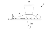
- the radiation imaging apparatus 51 includes a top plate 52 on which a subject is placed, a radiation source 53 provided so as to sandwich the top plate 52, and an FPD 54 that detects radiation.
- the radiation source 53 and the FPD 54 can move with respect to the top plate 52. If imaging is performed by moving the radiation source 53 and the FPD 54 to the position of the region of interest of the subject, an image in which the region of interest is reliably captured can be captured.
- the FPD 54 does not collide with an object M or an operator who operates the apparatus or peripheral equipment (hereinafter referred to as an object).
- an object an operator who operates the apparatus or peripheral equipment
- a capacitance type proximity sensor is provided. This proximity sensor is attached to the FPD 54 and can sense the approach of an object. As a result, when the target object abnormally approaches the FPD 54 or the like, the situation in which the FPD 54 collides with the target object can be avoided by stopping the movement of the FPD 54.
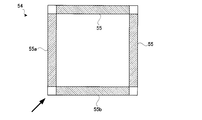
- the FPD 54 can move in any direction in the three-dimensional space. Therefore, in the conventional configuration, the abnormal approach of the object can be detected from which direction the FPD 54 approaches the object. That is, as shown in FIG. 13, one proximity sensor 55 is attached to each of the four sides of the rectangular FPD 54. Therefore, the FPD 54 is provided with four proximity sensors 55.
- proximity sensors 55 have different detection ranges.
- the detection range of the proximity sensor 55a provided on the left side in FIG. 13 is a space area on the left side of the page. Therefore, the proximity sensor 55a is in charge of detecting an object approaching toward the proximity sensor 55a.
- the space area on the lower side of the paper as viewed from the FPD 54 in FIG. 13 is not the detection range of the proximity sensor 55a. Therefore, the detection of an object approaching toward the proximity sensor 55b is handled by the proximity sensor 55b attached to the lower side of the drawing.
- the conventional configuration has the following problems. That is, according to the conventional configuration, a blind spot in which it is difficult to detect the approach of the object is generated by the portion of the FPD 54. For example, if an object approaches the FPD 54 toward the corner of the FPD 54 as indicated by an arrow in FIG. 13, the object is detected by the two proximity sensors 55a and 55b provided across the corner. It will be.
- the corner of the FPD 54 corresponds to the limit of the detection range of the two proximity sensors 55a and 55b. Therefore, the approach of the object cannot be detected with good sensitivity for any of the proximity sensors 55a and 55b. Therefore, when the object approaches toward the corner of the FPD 54, the approach of the object is not detected unless the object is closer than the other parts in the FPD 54.
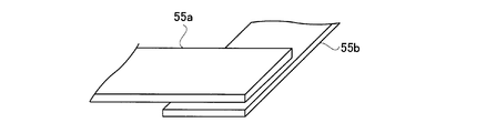
- the proximity sensors 55a and 55b cannot be arranged so as to simply overlap. This is because if another proximity sensor 55a is provided so as to cover the proximity sensor 55b, the covered proximity sensor 55b is obstructed by the proximity sensor 55a and cannot sense the approach of an object.
- the proximity sensor 55a exposed to the object is exclusively in charge of detecting the approach of the object for the portion where the proximity sensors 55a and 55b overlap.
- the present invention has been made in view of such circumstances, and an object of the present invention is to provide a radiation imaging apparatus with high safety by increasing the detection sensitivity of the proximity sensor.
- the radiographic apparatus detects a detection means for detecting radiation, a moving means for moving the detection means relative to the subject, a movement control means for controlling the moving means, and an approach of an object to the detection means.
- a plurality of proximity sensors that are provided so as to cover the proximity sensor and are not electrically connected to the object sensing electrode of the proximity sensor.
- the covering member is provided across the proximity sensors adjacent to each other.
- the detection means moves relative to the subject.
- the detection means is provided with a plurality of proximity sensors so as not to come into contact with the object during movement.
- a plurality of proximity sensors provided in the detection means, it is possible to know from which direction the object is approaching the detection means.
- the capacitive proximity sensor can sense the approach of an object by functioning as a capacitor with the approaching object.
- the covering member functions as an electrode of the capacitor. Therefore, the covering member can reliably increase the detection sensitivity of the proximity sensor.
- the proximity sensor is a capacitive type, the approach of the object may not be detected depending on the approaching direction of the object. Therefore, if the configuration of the present invention is applied to a capacitive proximity sensor, the direction in which the proximity sensor can detect the approach of an object increases. Specifically, the detection range in which the proximity sensor can recognize the approach of the object extends to the covering member, and the detection ranges of the proximity sensors adjacent to each other overlap. Thereby, the detection sensitivity of the approach of the object at the boundary between adjacent proximity sensors is enhanced.
- the covering member is made of carbon graphite.
- the above-described configuration shows a specific configuration of the radiation imaging apparatus of the present invention. If the covering member is made of a radiolucent carbon graphite, it is possible to provide a radiographic apparatus capable of acquiring a clear image without the covering member interfering with the radiation detection of the detecting means.
- the back surface for the detection means in the proximity sensor is not covered with another proximity sensor.
- the above-described configuration shows a specific configuration of the radiation imaging apparatus of the present invention. If the back surface for the detection means in the proximity sensor is not covered with another proximity sensor, one proximity sensor is not covered with the other proximity sensor and the detection sensitivity does not deteriorate.
- the proximity sensor is provided at the peripheral portion of the detection surface for detecting the radiation in the detection means.
- the above-described configuration shows a specific configuration of the radiation imaging apparatus of the present invention. If the proximity sensor is provided at the periphery of the detection surface for detecting radiation in the detection means, a radiation imaging apparatus that can reliably detect the approach of the object to the detection means can be provided.
- the above-described radiation imaging apparatus includes a radiation source for irradiating radiation and a C arm that supports the radiation source and the detection means, and the moving means operates by moving the C arm.
- the configuration of the present invention shows a specific configuration of the radiation imaging apparatus of the present invention. Since the radiographic apparatus in which the detection means is supported by the C arm has a higher degree of freedom of movement of the detection means than the type of apparatus in which the detection means moves in parallel with the top plate, the configuration of the present invention includes the C arm. It is more effective when applied to a radiographic apparatus.
- the detection means moves with respect to the subject.
- the detection means is provided with a plurality of proximity sensors so as not to come into contact with the object during movement.
- a plurality of proximity sensors provided in the detection means, it is possible to know from which direction the object is approaching the detection means.
- coated member is provided ranging over several proximity sensors. In this way, since the sensitivity with which the proximity sensor detects an object increases, it is possible to provide a radiation imaging apparatus that operates safely by more accurately detecting the approach of the object in the detection means.
- FIG. 1 is a functional block diagram illustrating a configuration of an X-ray imaging apparatus according to Embodiment 1.
- FIG. FIG. 6 is a schematic diagram for explaining the movement of the C-arm according to the first embodiment. It is a perspective view explaining the structure of the proximity sensor which concerns on Example 1.
- FIG. It is a perspective view explaining arrangement
- FIG. FIG. 3 is a perspective view illustrating the arrangement of the covering member according to the first embodiment.
- FIG. 3 is a plan view for explaining the arrangement of covering members according to the first embodiment. It is sectional drawing explaining the structure of the proximity sensor which concerns on Example 1.
- FIG. FIG. 6 is a cross-sectional view illustrating the operation of the proximity sensor according to the first embodiment.
- FIG. 6 is a schematic diagram illustrating a detection range of the proximity sensor according to Embodiment 1.
- FIG. 6 is a schematic diagram illustrating a detection range of the proximity sensor according to Embodiment 1.
- FIG. It is a mimetic diagram explaining one modification of the present invention. It is a schematic diagram explaining the structure of the X-ray imaging apparatus of a conventional structure. It is a top view explaining arrangement
- Top plate 3 X-ray tube (radiation source) 4 FPD (detection means) 5 proximity sensor 7 C arm 9 covering member 21 C arm moving mechanism (moving means) 22 C-arm movement control unit (movement control means)
- X-rays in the examples correspond to the radiation of the present invention.
- FPD is an abbreviation for flat panel detector.
- an X-ray imaging apparatus 1 includes a top plate 2 on which a subject M is placed, and an X-ray tube 3 that emits X-rays provided below the top plate 2.
- the FPD 4 for detecting X-rays provided on the upper side of the top plate 2, the X-ray tube control unit 6 for controlling the tube current and tube voltage of the X-ray tube 3, and the C-arm for supporting the X-ray tube 3 and the FPD 4 7, a support column 8 that supports the C arm 7, a C arm movement mechanism 21 that moves the C arm 7, and a C arm movement control unit 22 that controls the C arm movement mechanism 21.
- the X-ray tube 3 corresponds to the radiation source of the present invention
- the FPD 4 corresponds to the radiation detector of the present invention
- the C arm movement mechanism 21 corresponds to the movement means of the present invention
- the C arm movement control unit 22 corresponds to the movement control means of the present invention.
- the C-arm 7 can be moved in the vertical direction and the horizontal direction by the C-arm moving mechanism 21 or can be rotated. That is, the C-arm 7 can be rotated along a virtual circle VA along which the curved C-arm 7 is curved as shown on the left side of FIG.
- the C-arm 7 can also rotate so that both ends are along a virtual circle VB on a plane orthogonal to the projecting direction.
- the virtual circle VA exists on a plane orthogonal to the body side direction S of the subject.
- the proximity sensor 5 is a capacitive proximity sensor that can detect the approach of an object.
- the FPD 4 is provided with a plurality of proximity sensors 5.
- the proximity sensor 5 has a strip-shaped sensor module as shown in FIG. This sensor module sequentially generates a signal representing the degree of approach of the object.
- FIG. 4 shows a state in which the proximity sensor 5 is attached to the FPD 4.
- four proximity sensors 5 are provided in the FPD 4.
- one sensor module described in FIG. 3 is provided at one end of the peripheral portion of the detection surface 4 a of the FPD 4, and one sensor module is also provided on the side end surface of the FPD 4.
- the meeting parts of the side end surfaces adjacent to each other in the FPD 4 are chamfered, and each of the surfaces generated by the chamfering is provided with two sensor modules arranged in a direction perpendicular to the side that has disappeared due to the chamfering. Yes.
- one of the peripheral portions of the detection surface 4a is adjacent to a certain side end surface.
- Two of the surfaces generated by chamfering are adjacent to a certain side end surface. That is, each side end surface has three adjacent surfaces (adjacent surfaces).
- the proximity sensor 5 is comprised from the sensor module provided in the side end surface, and the three sensor modules provided in the three adjacent surfaces about the side end surface. Therefore, the proximity sensor 5 has four sensor modules.
- one proximity sensor 5 is provided on each of the four sides of the FPD 4, and one of the proximity sensors 5 is an object that approaches one of the four sensor modules constituting the proximity sensor 5. Can be sensed.
- Two sensor modules are provided on the surface generated by chamfering. These sensor modules form one proximity sensor 5 together with the sensor modules provided on the side end surfaces adjacent to each other.
- the detection surface 4a is provided with the four proximity sensors 5, by comparing the outputs of the four proximity sensors 5, it is possible to know from which direction the object is approaching the detection surface 4a.
- the opposite surface when viewed from the FPD 4 is a sensing surface that senses the approach of the object.
- the sensing surface is not covered with another proximity sensor 5. This is because if the proximity sensor 5 is provided so as to cover the sensing surface, the sensitivity of the covered proximity sensor 5 deteriorates. That is, the back surface for the FPD 4 among the surfaces of the proximity sensor 5 is not covered with the other proximity sensors 5.
- FIG. 5 is a diagram illustrating the conductive covering member 9 provided so as to cover the proximity sensor 5.
- the covering member 9 is provided across the two proximity sensors 5 adjacent to each other. Therefore, the covering member 9 is provided on a surface generated by chamfering the side of the FPD 4. By doing in this way, the sensitivity of the proximity sensor 5 in the corner
- the covering member 9 is made of a conductor, and is particularly made of carbon graphite that does not interfere with X-ray imaging due to the property of easily transmitting X-rays.
- the covering member 9 is not electrically connected to the object sensing electrode 5c of the proximity sensor 5 and is insulated through the protective cover 5d3 (see FIG. 7).
- FIG. 6 shows how the covering member 9 is arranged in the entire FPD 4.
- the covering member 9 is provided at four corners of the FPD 4 so as to cover the meeting portions of the proximity sensors 5 adjacent to each other.
- the covering member 9 is provided on a surface generated by chamfering at the corner of the FPD 4.
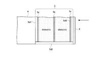
- FIG. 7 is a cross-sectional view showing the proximity sensor 5 (exactly one of the sensor modules included in the proximity sensor 5) and the covering member 9 provided on the detection surface 4a of the FPD 4. It is assumed that X-rays enter the FPD 4 from the direction of the arrow in FIG.
- the strip-shaped proximity sensor 5 is provided with three plate-like electrodes 5a, 5b, 5c laminated in the thickness direction in this order, and a dielectric is provided between the electrodes 5a, 5b, 5c. Intervene.
- Each electrode 5a, 5b, 5c is covered with a non-conductive protective cover 5d1, 5d2, 5d3 for protecting them.
- the electrode closer to the FPD 4 is 5a
- the electrode closer to the covering member 9 is 5c.
- the electrode 5a is referred to as a ground electrode
- the electrode 5b is referred to as a shield electrode
- the electrode 5c is referred to as a transmitting / receiving electrode.
- FIG. 8 shows a state in which the proximity sensor 5 which is a capacitance type detects the approach of the object Obj.
- the ground electrode 5a and the object Obj are grounded, and the potential is zero.
- An AC voltage is applied to the shield electrode 5b, and the potential of the shield electrode 5b varies with time.
- the potential of the shield electrode 5b is regarded as a time variable and expressed as V (t).
- the dual-purpose electrode 5c is V (t) having the same potential as the shield electrode 5b. The reason why two electrodes having the same potential are provided will be described later.
- the ground electrode 5a, the shield electrode 5b, and the dielectric interposed between the electrodes 5a and 5b can be regarded as one capacitor.
- the electrostatic capacity at this time is C1. Since the voltage of the shield electrode 5b varies with time, a weak current ⁇ flows between both electrodes.
- the combined electrode 5c, the covering member 9, and the non-conductive protective cover 5d3 that insulates them can be regarded as one capacitor.
- the electrostatic capacity at this time is C2.
- the covering member 9, the object Obj, and the dielectric interposed therebetween can be regarded as one capacitor.
- the electrostatic capacity at this time is defined as electrostatic capacity C3.
- two capacitors are electrically arranged in series between the dual-purpose electrode 5c and the object Obj. It can be seen that a capacitor having a total capacitance of the capacitance C2 and the capacitance C3 is interposed from the shared electrode 5c to the object Obj. If the voltage of the dual-purpose electrode 5c varies with time, a weak current ⁇ flows from the dual-purpose electrode 5c to the object Obj.
- the combined electrode 5c is provided for the purpose of measuring the current ⁇ .
- the shield electrode 5b is provided for the purpose of measuring the current ⁇ .
- the reason why two electrodes having the same potential are provided will be described.
- the potentials of the electrodes 5b and 5c are set to the same potential so that no electrostatic capacitance is generated between the electrodes 5b and 5c.
- an electrostatic capacity does not arise between both electrodes. That is, if the electrodes 5b and 5c are set to the same potential, the gap between the electrodes 5b and 5c can be narrowed, so that the proximity sensor 5 with a further reduced thickness can be configured.
- the manner in which the proximity sensor 5 senses the approach of the object Obj by measuring the current ⁇ and the current ⁇ will be described.
- the temporal changes in the current ⁇ and the current ⁇ have the same behavior. This is because the shield electrode 5b and the dual-purpose electrode 5c have the same potential, and the ground electrode 5a and the object Obj have the same potential.
- the electrostatic capacitance C3 that determines the magnitude of the current ⁇ changes. Then, the pattern of change with time of the current ⁇ does not match the pattern of change with time of the current ⁇ .
- the proximity sensor 5 can detect a change with time of the electrostatic capacitance C3 by simultaneously monitoring and comparing the current ⁇ and the current ⁇ . Since the electrostatic capacity C3 varies depending on the change in the distance between the proximity sensor 5 and the object Obj, if the electrostatic capacity C3 is continuously detected, the approach of the object Obj to the proximity sensor 5 can be detected.
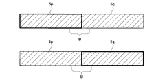
- FIG. 9 shows detection ranges of the proximity sensors 5p and 5q adjacent to each other.
- the dual-purpose electrode 5c of the proximity sensor 5 and the object Obj must face each other so as to serve as both poles of a capacitor.
- the upper part of FIG. 9 shows a range in which the proximity sensor 5p can detect the approach of an object.
- the proximity sensor 5p can detect the approach of an object that faces the area surrounded by a thick frame in the upper part of FIG.
- the proximity sensor 5q can detect the approach of an object that faces the area surrounded by a thick frame in the lower part of FIG.
- the boundary B When attention is paid to the boundary B in the proximity sensors 5p and 5q adjacent to each other, the boundary B is located at the limit of the detection range in the proximity sensors 5p and 5q adjacent to each other. Therefore, both the proximity sensors 5p and 5q are detected with low sensitivity for an object approaching toward the boundary B.
- FIG. 10 illustrates the detection range when the covering member 9 is provided across the proximity sensors 5p and 5q adjacent to each other.
- the upper part of FIG. 10 shows a state in which the covering member 9 is provided across the proximity sensors 5p and 5q.
- the proximity sensor 5p can detect the approach of an object.
- the proximity sensor 5p can detect the approach of an object that faces the area surrounded by a thick frame in the middle of FIG.
- the detection range of the proximity sensor 5p extends to the covering member 9. That is, in the case where the covering member 9 is interposed between the proximity sensor 5p and the object, the proximity sensor 5p only needs to face the object as long as the covering member 9 and the object face each other so as to serve as both poles of the capacitor. Can be detected.
- the lower part of FIG. 10 shows a range in which the proximity sensor 5q can detect the approach of an object.
- the proximity sensor 5q can detect the approach of an object that faces the area surrounded by a thick frame in the lower part of FIG.
- the detection range of the proximity sensor 5q extends to the covering member 9. That is, in the case where the covering member 9 is interposed between the proximity sensor 5q and the object, the proximity sensor 5q is only required to face the object as long as the covering member 9 and the object face each other so as to serve as the two poles of the capacitor. Can be detected.
- the boundary portion B of the proximity sensors 5p and 5q adjacent to each other belongs to any of the detection ranges of the proximity sensors 5p and 5q adjacent to each other. Accordingly, an object approaching toward the boundary B is detected with high sensitivity by both the proximity sensors 5p and 5q.
- the detection areas of the proximity sensors 5p and 5q adjacent to each other overlap. That is, the proximity sensor 5p can detect not only the approach of the object facing the proximity sensor 5p but also the approach of the object facing the covering member 9.
- the proximity sensor 5q can detect not only the approach of the object facing the proximity sensor 5q but also the approach of the object facing the covering member 9.
- the proximity sensors 5p and 5q are provided with exposed portions that are not covered by the covering member 9. If the entire proximity sensors 5p and 5q are covered with one covering member 9, the two proximity sensors 5p and 5q sense the approach of the object as if they were one proximity sensor, and the proximity sensor This is because the advantage of providing 5 independently is lost.
- the image generation unit 11 receives an X-ray detection signal from the FPD 4 and generates an image P0 in which a fluoroscopic image of the subject is reflected.
- the console 31 is used to input various instructions from the operator.
- the display unit 32 is provided for the purpose of displaying the image P0.
- the X-ray imaging apparatus 1 includes a main control unit 34 that comprehensively controls the units 6, 11, and 22.
- the main control unit 34 is configured by a CPU, and realizes each unit by executing various programs. Further, each of the above-described units may be divided and executed by an arithmetic device that takes charge of them.
- the output of the proximity sensor 5 is sent to the C-arm movement control unit 22.
- the C arm movement control unit 22 performs the movement of the C arm 7 while monitoring the output of the proximity sensor 5. That is, when the surgeon gives an instruction to move the C-arm 7 through the console 31, the C-arm movement control unit 22 moves the C-arm 7 in accordance with this instruction, and whether there is a report of abnormal approach by the proximity sensor 5. Is monitoring. As the C-arm 7 is moved, if an object abnormally approaches the FPD 4, the C-arm movement control unit 22 detects this through the proximity sensor 5 and stops the movement of the C-arm 7. Thereby, it is possible to prevent the C-arm 7 from contacting an object such as the subject M in advance.
- the monitoring of the abnormal object approach through the proximity sensor 5 in the C-arm movement control unit 22 is not limited to the case where the surgeon instructs the movement. That is, when taking a tomographic image of the subject M, the C-arm 7 is automatically rotated by the C-arm movement control unit 22 as shown on the right side of FIG. Even in this case, the C-arm movement control unit 22 detects the abnormal approach of the object through the proximity sensor 5 and stops the movement of the C-arm 7. At this time, the C-arm movement control unit 22 also sends data notifying the abnormal approach to the X-ray tube control unit 6. Upon receiving this data transmission, the X-ray tube control unit 6 interrupts X-ray irradiation.
- the C-arm movement control unit 22 may move the C-arm 7 so that the FPD 4 moves in the direction opposite to the approaching direction of the object detected by the approach sensor 5 when the object abnormally approaches.
- the FPD 4 moves relative to the subject M.
- the FPD 4 is provided with a plurality of proximity sensors 5 so as not to contact the subject M during movement.
- a plurality of proximity sensors 5 provided in the FPD 4 it is possible to know from which direction the top plate 2 is approaching the FPD 4.
- coated member 9 is provided ranging over the proximity sensor 5 which adjoins mutually.
- the capacitive proximity sensor 5 can sense the approach of an object by functioning as a capacitor together with the approaching object.
- the covering member 9 functions as an electrode of a capacitor, so that the covering member 9 can reliably increase the detection sensitivity of the proximity sensor 5.
- the proximity sensor 5 is a capacitance type. Then, depending on the direction in which the object approaches, the proximity sensor 5 may not be able to sense the approach of the object. Therefore, if the configuration of the first embodiment is applied to the capacitive proximity sensor 5, the direction in which the proximity sensor 5 can detect the approach of an object increases. Specifically, the detection range in which the proximity sensor 5 can recognize the approach of the object extends to the covering member 9, and the detection ranges of the proximity sensors 5 adjacent to each other overlap. Thereby, the detection sensitivity of the approach of the object at the boundary between the proximity sensors 5 adjacent to each other is enhanced.
- one proximity sensor 5 may be covered with the other proximity sensor 5 and the detection sensitivity may deteriorate. Absent.
- an X-ray imaging apparatus that can reliably detect the approach of the top 2 to the FPD 4. 1 can be provided.
- the X-ray imaging apparatus 1 in which the FPD 4 is supported by the C arm 7 has a higher degree of freedom of movement of the FPD 4 than the apparatus of the type in which the FPD 4 moves in parallel with the top plate 2. If the present invention is applied to the X-ray imaging apparatus 1 having 7, it is more effective.
- the present invention is not limited to the above-described configuration and can be modified as follows.
- the covering member 9 is provided across the two proximity sensors 5 provided in the FPD 4 illustrated in FIG. 4, but the present invention is not limited to this configuration. That is, as shown in FIG. 11, the covering member 9 may be provided so as to straddle the two proximity sensors 5 provided on the detection surface 4a of the FPD 4, or the proximity sensor 5 provided on the detection surface 4a and the side. The covering member 9 may be provided so as to straddle the proximity sensor 5 provided on the end face. At this time, the covering member 9 is disposed so as to cover a part of the detection surface 4 a of the FPD 4. Since the covering member 9 is made of carbon graphite that easily transmits X-rays, the covering member 9 does not obstruct X-ray transmission, and the shadow of the covering member 9 does not appear in the image.
- the covering member 9 is provided across the two proximity sensors 5 provided in the FPD 4 shown in FIG. 4, but the present invention is not limited to this configuration. That is, the covering member 9 may be provided so as to straddle three or more proximity sensors 5. As a specific example in this case, by providing the covering member 9 so as to cover the intersection between the detection surface 4a of the FPD 4 and the two side end surfaces, two approaches in which the covering member 9 is provided on the detection surface 4a. You may make it cover the sensor 5 and the two proximity sensors 5 provided in the side end surface.
- the X-ray referred to in the above-described embodiments is an example of radiation in the present invention. Therefore, the present invention can be applied to radiation other than X-rays.
- the present invention is suitable for a medical radiation imaging apparatus.
Landscapes
- Health & Medical Sciences (AREA)
- Life Sciences & Earth Sciences (AREA)
- Medical Informatics (AREA)
- Engineering & Computer Science (AREA)
- Radiology & Medical Imaging (AREA)
- Biomedical Technology (AREA)
- Biophysics (AREA)
- Nuclear Medicine, Radiotherapy & Molecular Imaging (AREA)
- Optics & Photonics (AREA)
- Pathology (AREA)
- Physics & Mathematics (AREA)
- High Energy & Nuclear Physics (AREA)
- Heart & Thoracic Surgery (AREA)
- Molecular Biology (AREA)
- Surgery (AREA)
- Animal Behavior & Ethology (AREA)
- General Health & Medical Sciences (AREA)
- Public Health (AREA)
- Veterinary Medicine (AREA)
- Apparatus For Radiation Diagnosis (AREA)
Abstract
FPD4が天板2に対して移動可能となっているとともに、移動中に天板2と接触しないようにFPD4に複数の接近センサ5が設けられている放射線撮影装置において、接近センサ5の検出感度を高めることによって安全性の高い放射線撮影装置を提供する。すなわち、本発明に係る放射線撮影装置には、被覆部材9が複数の接近センサ5に跨って設けられている。この様にすることで、接近センサ5が物体を検出する感度が増加するので、より安全に動作する放射線撮影装置が提供できる。
Description
本発明は、被検体に放射線を照射して、画像を取得する放射線撮影装置に関し、特に、装置の部材同士が衝突しないように静電容量式の接近センサを備える放射線撮影装置に関する。
医療機関には、被検体に放射線を照射して画像を取得する放射線撮影装置が配備されている。このような放射線撮影装置51は、図12に示すように、被検体を載置する天板52と、天板52を挟むようにして設けられた放射線源53および放射線を検出するFPD54を備えている。
放射線源53およびFPD54は天板52に対して移動できるようになっている。放射線源53およびFPD54を被検体の関心部位の位置に移動させて撮影を行うようにすれば、関心部位が確実に写り込んだ画像が撮影できる。
従来の放射線撮影装置51には、特許文献1,特許文献2に示すように、FPD54が被検体Mや装置を操作する操作者や周辺機器(以下これらを対象物と称する)に衝突しないようにする目的で静電容量式の接近センサを備えている。この接近センサはFPD54に付設して設けられており、対象物の接近を感知することができる。これにより対象物がFPD54などに異常接近した場合に、FPD54の移動を停止することで、FPD54が対象物に衝突する事態を免れることができる。
FPD54は、3次元空間内をどの方向にも移動することができる。したがって、従来構成においては、FPD54がどの方向から対象物に近づいても対象物の異常接近が検出できるようになっている。すなわち、接近センサ55は図13に示すように、矩形となっているFPD54の4辺の各々に1ずつ付設されている。したがって、FPD54には、接近センサ55が4つ設けられていることになる。
これら、接近センサ55は、それぞれ異なる検出範囲を有している。例えば図13において紙面左側に設けられている接近センサ55aの検出範囲は、紙面左側の空間領域である。したがって、接近センサ55aに向けて接近する物体の検出はこの接近センサ55aが担当する。一方、図13におけるFPD54からみて紙面下側の空間領域は、接近センサ55aの検出範囲ではない。そこで、接近センサ55bに向けて接近する物体の検出は、紙面下側に付設の接近センサ55bが担当することになる。
特開2001-336908号公報
特開2006-81739号公報
しかしながら、従来構成によれば次のような問題点がある。
すなわち、従来構成によれば、FPD54の部分によって物体の接近の検出が困難な死角が生じてしまう。例えば、図13の矢印の示すようにFPD54の角部に向けて物体がFPD54に接近したとすると、この物体は、この角部を挟んで設けられた2つの接近センサ55a,55bによって検出されることになる。FPD54の角部は、2つの接近センサ55a,55bにおける検出範囲の限界に当たる。したがって、いずれの接近センサ55a,55bにとっても良好な感度で物体の接近を検出することができない。したがって、FPD54の角部に向けて物体が接近すると、FPD54におけるその他の部分と比べてより物体が接近しなければ、物体の接近が検出されないことになる。
すなわち、従来構成によれば、FPD54の部分によって物体の接近の検出が困難な死角が生じてしまう。例えば、図13の矢印の示すようにFPD54の角部に向けて物体がFPD54に接近したとすると、この物体は、この角部を挟んで設けられた2つの接近センサ55a,55bによって検出されることになる。FPD54の角部は、2つの接近センサ55a,55bにおける検出範囲の限界に当たる。したがって、いずれの接近センサ55a,55bにとっても良好な感度で物体の接近を検出することができない。したがって、FPD54の角部に向けて物体が接近すると、FPD54におけるその他の部分と比べてより物体が接近しなければ、物体の接近が検出されないことになる。
この様な事態を回避するには、隣接する接近センサ55a,55bの検出範囲をオーバーラップさせる必要がある。しかし、図14に示すように、接近センサ55a,55bを単純にオーバーラップさせるように配置することはできない。接近センサ55bを覆うように別の接近センサ55a設けると、覆われた方の接近センサ55bは、接近センサ55aに邪魔されて、物体の接近を感知することができなくなってしまうからである。接近センサ55a,55bがオーバーラップしている部分についての物体接近の検出は、専ら物体に対して露出している接近センサ55aが担当することになる。
本発明は、この様な事情に鑑みてなされたものであって、その目的は、接近センサの検出感度を高めることによって安全性の高い放射線撮影装置を提供することにある。
本発明は上述の課題を解決するために次のような構成をとる。
すなわち、本発明に係る放射線撮影装置は、放射線を検出する検出手段と、被検体に対し検出手段を移動させる移動手段と、移動手段を制御する移動制御手段と、検出手段に対する物体の接近を検出する静電容量式の接近センサと、接近センサを覆うように設けられるとともに接近センサの有する物体感知用の電極に電気的に接続されていない導体の被覆部材とを備え、複数の接近センサが検出手段に設けられているとともに、被覆部材が互いに隣接する接近センサに跨って設けられていることを特徴とするものである。
すなわち、本発明に係る放射線撮影装置は、放射線を検出する検出手段と、被検体に対し検出手段を移動させる移動手段と、移動手段を制御する移動制御手段と、検出手段に対する物体の接近を検出する静電容量式の接近センサと、接近センサを覆うように設けられるとともに接近センサの有する物体感知用の電極に電気的に接続されていない導体の被覆部材とを備え、複数の接近センサが検出手段に設けられているとともに、被覆部材が互いに隣接する接近センサに跨って設けられていることを特徴とするものである。
[作用・効果]本発明の構成によれば、検出手段が被検体に対して移動するようになっている。そして、検出手段には移動中に対象物と接触しないように複数の接近センサが設けられている。検出手段に設ける接近センサを複数とすることで検出手段に対象物がどの方向から接近しているかが分かるようになっている。
静電容量式の接近センサは、接近する物体とともにコンデンサとして機能することにより物体の接近を感知できる。被覆部材を導体とすることで、被覆部材がコンデンサの電極として機能することになるので、被覆部材は確実に接近センサの検出感度を増加させることができる。
接近センサが静電容量式であるので、物体の近づく方向によっては、物体の接近を感知できない場合がある。従って、静電容量式の接近センサに本発明の構成を適用すれば、接近センサが物体の接近を検出可能な方向が増加する。具体的には、接近センサが有する物体の接近を認識できる検出範囲が被覆部材まで広がり、互いに隣接する接近センサの検出範囲がオーバーラップすることになる。これにより、互いに隣接する接近センサの境目における物体の接近の検出感度が強化される。
また、上述の放射線撮影装置において、被覆部材がカーボングラファイトで構成されればより望ましい。
[作用・効果]上述の構成は、本発明の放射線撮影装置の具体的構成を示すものとなっている。被覆部材を放射線透過性のカーボングラファイトで構成すれば、被覆部材が検出手段の放射線検出の邪魔をすることがなく、鮮明な画像が取得できる放射線撮影装置が提供できる。
また、上述の放射線撮影装置において、接近センサにおける検出手段にとっての裏面は、他の接近センサにより被覆されていなければより望ましい。
[作用・効果]上述の構成は、本発明の放射線撮影装置の具体的構成を示すものとなっている。接近センサにおける検出手段にとっての裏面が他の接近センサにより被覆されないようにすれば、一方の接近センサが他方の接近センサに覆われて検出感度が悪化してしまうことがない。
また、上述の放射線撮影装置において、接近センサは、検出手段における放射線を検出する検出面の周縁部に設けられていればより望ましい。
[作用・効果]上述の構成は、本発明の放射線撮影装置の具体的構成を示すものとなっている。接近センサが検出手段における放射線を検出する検出面の周縁部に設けられていれば、検出手段に対する対象物の接近を確実に検出することができる放射線撮影装置が提供できる。
また、上述の放射線撮影装置において、放射線を照射する放射線源と、放射線源および検出手段を支持するCアームとを備え、移動手段はCアームを移動させることにより動作すればより望ましい。
[作用・効果]上述の構成は、本発明の放射線撮影装置の具体的構成を示すものとなっている。検出手段がCアームで支持される放射線撮影装置は、検出手段が天板と平行移動するタイプの装置と比べて検出手段の移動の自由度がより高いので、本発明の構成をCアームを備えた放射線撮影装置に適用すれば、より効果的である。
本発明の構成によれば、検出手段が被検体に対して移動するようになっている。そして、検出手段には移動中に対象物と接触しないように複数の接近センサが設けられている。検出手段に設ける接近センサを複数とすることで検出手段に対象物がどの方向から接近しているかが分かるようになっている。そして、本発明においては、被覆部材が複数の接近センサに跨って設けられている。この様にすることで、接近センサが物体を検出する感度が増加するので、検出手段における物体の接近をより正確に検知して安全に動作する放射線撮影装置が提供できる。
2 天板
3 X線管(放射線源)
4 FPD(検出手段)
5 接近センサ
7 Cアーム
9 被覆部材
21 Cアーム移動機構(移動手段)
22 Cアーム移動制御部(移動制御手段)
3 X線管(放射線源)
4 FPD(検出手段)
5 接近センサ
7 Cアーム
9 被覆部材
21 Cアーム移動機構(移動手段)
22 Cアーム移動制御部(移動制御手段)
以降、本発明における最良の形態について説明する。実施例におけるX線は、本発明の放射線に相当する。また、FPDは、フラット・パネル・ディテクタの略である。
<X線撮影装置の構成>
実施例1に係るX線撮影装置1は、図1に示すように被検体Mを載置する天板2と、天板2の下側に設けられたX線を照射するX線管3と、天板2の上側に設けられたX線を検出するFPD4と、X線管3の管電流、管電圧を制御するX線管制御部6と、X線管3およびFPD4を支持するCアーム7と、Cアーム7を支持する支柱8と、Cアーム7を移動させるCアーム移動機構21と、これを制御するCアーム移動制御部22とを備えている。X線管3は、本発明の放射線源に相当し、FPD4は、本発明の放射線検出器に相当する。Cアーム移動機構21は、本発明の移動手段に相当し、Cアーム移動制御部22は、本発明の移動制御手段に相当する。
実施例1に係るX線撮影装置1は、図1に示すように被検体Mを載置する天板2と、天板2の下側に設けられたX線を照射するX線管3と、天板2の上側に設けられたX線を検出するFPD4と、X線管3の管電流、管電圧を制御するX線管制御部6と、X線管3およびFPD4を支持するCアーム7と、Cアーム7を支持する支柱8と、Cアーム7を移動させるCアーム移動機構21と、これを制御するCアーム移動制御部22とを備えている。X線管3は、本発明の放射線源に相当し、FPD4は、本発明の放射線検出器に相当する。Cアーム移動機構21は、本発明の移動手段に相当し、Cアーム移動制御部22は、本発明の移動制御手段に相当する。
Cアーム7は、Cアーム移動機構21により、鉛直方向、水平方向に移動することもできれば回転することもできる。すなわち、Cアーム7は、図2左側に示すように湾曲したCアーム7が沿う仮想円VAに沿って回転することもできれば、図2右側に示すように、Cアーム7の両端が支柱8から突き出す方向を突出方向(体軸方向A)としたとき、Cアーム7は、突出方向と直交する平面上の仮想円VBに両端が沿うように回転することもできる。仮想円VAは被検体の体側方向Sと直交する平面上に存在している。
接近センサ5は、物体の接近を検出できる静電容量式の接近センサである。FPD4には複数の接近センサ5が設けられている。接近センサ5は、図3に示すように、短冊状のセンサモジュールを有している。このセンサモジュールは物体の接近の程度を表す信号を逐次発生する。
図4は、接近センサ5がFPD4に付設される様子を示している。図4においては、4つ接近センサ5がFPD4に設けられている。図4に示すように、FPD4の検出面4aにおける周縁部の一端に図3で説明したセンサモジュールが1つ設けられており、FPD4の側端面にもセンサモジュールが1つ設けられている。FPD4における互いに隣接する側端面の会合部には面取りがされており、面取りによって生じた面の各々には、面取りにより消失した側辺と直交する方向に配列された2つのセンサモジュールが設けられている。
図4に示すように検出面4aの周縁部のうちの1つは、ある側端面に隣接している。また、面取りによって生じた面のうちの2つは、ある側端面の両隣となっている。つまり、側端面の各々には、3つの隣接する面(隣接面)があることになる。そして、接近センサ5は、側端面に設けられているセンサモジュールと、その側端面についての3つの隣接面に設けられている3つのセンサモジュールとから構成される。したがって、接近センサ5は、4つのセンサモジュールを有していることになる。また、図4においては、接近センサ5はFPD4の四辺の各々に1ずつ設けられており、うち1つの接近センサ5は、接近センサ5を構成する4つのセンサモジュールのいずれかに接近する物体を感知することができる。なお、面取りによって生じた面には2つのセンサモジュールが設けられている。これらのセンサモジュールは、それぞれに隣接する側端面に設けられたセンサモジュールとともに1つの接近センサ5を形成する。
検出面4aには、4つの接近センサ5が設けられているので、4つの接近センサ5の出力を比較すれば、物体がどの方向から検出面4aに近づこうとしているかを知ることができる。
また、接近センサ5の各面のうちFPD4から見たときの反対側の面は、物体の接近を感知する感知面となっている。実施例1の構成においては、感知面は、他の接近センサ5により被覆されていない。感知面を覆うように接近センサ5を設けてしまうと、覆われた方の接近センサ5の感度が悪化するからである。すなわち、接近センサ5が有する各面のうちFPD4にとっての裏面は、他の接近センサ5により被覆されていない。
図5は、接近センサ5を覆うように設けられる導電性の被覆部材9について説明する図である。被覆部材9は、図5に示すように、互いに隣接する2つの接近センサ5に跨って設けられている。したがって、被覆部材9は、FPD4の側辺を面取りすることによって生じた面に設けられている。この様にすることで、物体が接近しやすいFPD4の角部における接近センサ5の感度が改善される。この被覆部材9は、導体で構成され、特にX線を透過しやすい性質によりX線撮影の邪魔とならないカーボングラファイトで構成される。また、この被覆部材9は、接近センサ5の有する物体感知用の電極5cには電気的に接続されておらず保護カバー5d3を介して絶縁される(図7参照)。
図6は、FPD4全体において被覆部材9がどのように配置されているかを示している。被覆部材9は、互いに隣接する接近センサ5の会合部を被覆するようにFPD4における4つの角部に設けられている。図6においては、被覆部材9は、FPD4の角部における面取によって生じた面に設けられている。
図7は、FPD4の検出面4aに設けられた接近センサ5(正確には、接近センサ5が有するセンサモジュールのうちの1つ)および被覆部材9を示す断面図である。FPD4には、図7における矢印の方向からX線が入射するものとする。短冊状となっている接近センサ5は厚さ方向に積層された3つの板状の電極5a,5b,5cがこの順に設けられており、各電極5a,5b,5cの間には誘電体が介在する。各電極5a,5b,5cは、これらを保護する不導体の保護カバー5d1,5d2,5d3により覆われている。3つの電極5a,5b,5cのうちFPD4に近い側の電極を5aとし、被覆部材9に近い側の電極を5cとする。以降、電極5aを接地電極、電極5bをシールド電極、電極5cを送受信兼用の兼用電極と呼ぶことにする。
図8は、静電容量式となっている接近センサ5が物体Objの接近を検出する様子を示している。接地電極5aと物体Objとは接地されており、電位は0となっている。そして、シールド電極5bには、交流の電圧が印加されており、シールド電極5bの電位は時間的に変動する。図8においてはシールド電極5bの電位を時間変数と捉えてV(t)と表している。兼用電極5cは、シールド電極5bと同電位のV(t)である。同電位の電極を2つ設ける理由については後述とする。
接地電極5a,シールド電極5b,および両電極5a,5bに介在する誘電体は、これで1つのコンデンサと見ることができる。このときの静電気容量をC1とする。シールド電極5bの電圧は時間的に変動するので、両電極間には弱い電流αが流れる。
兼用電極5c,被覆部材9およびこれらを絶縁する不導体の保護カバー5d3はこれで一つのコンデンサと見ることができる。このときの静電気容量をC2とする。また、被覆部材9,物体Objおよびこれらに介在する誘電体は、これで1つのコンデンサと見ることができる。このときの静電気容量を静電気容量C3とする。つまり、兼用電極5cと物体Objとの間は電気的に2つのコンデンサが直列に配列されている状態となっている。そして、兼用電極5cから物体Objには電気容量C2と電気容量C3との合計の電気容量のコンデンサが介在していると見ることができる。兼用電極5cの電圧は時間的に変動することからすれば、兼用電極5cから物体Objにかけて微弱な電流βが流れることになる。
兼用電極5cは、電流βを測定する目的で設けられている。そして、シールド電極5bは、電流αを測定する目的で設けられている。この様にすると、電位の異なる2つの電極を介して物体の接近を検出するような構成とするよりも装置を小型化できるとともに、物体の接近が検出できる範囲が広いものとなる。
同電位の電極を2つ設ける理由について説明する。一般に2つの電極が対向すると、両電極間に静電容量が生じる。接近センサ5においてこの現象が起こると電流α、電流βが正確に測定できなくなる。そこで、実施例1の構成によれば、両電極5b,5cの間に静電容量が生じないように両電極5b,5cの電位を同電位としている。この様にすることで、両電極5b,5cを接近させても両電極間に静電容量が生じない。つまり、両電極5b,5cを同電位とすると両電極5b,5cの間の隙間を狭くすることができるので、より厚みが抑制された接近センサ5が構成できる。
接近センサ5が電流αと電流βとを測定することにより物体Objの接近を感知する様子について説明する。電流αと電流βとの時間的変化は互いに同じ挙動となる。シールド電極5b,兼用電極5cとが互いに同電位であり、接地電極5aと物体Objとが互いに同電位だからである。しかし、この状態から物体Objが接近センサ5に近づくと、電流βの大きさを決める静電気容量C3が変化する。すると、電流βの経時変化のパターンが電流αの経時変化のパターンと一致しなくなる。このように接近センサ5は電流αと電流βとを同時にモニタして比較することにより静電気容量C3の経時変化を検出することができる。静電気容量C3は、接近センサ5と物体Objとの距離の変化に依存して変動するので、静電気容量C3の検出を続ければ、接近センサ5に対する物体Objの接近が検出できることになる。
図9は、互いに隣接する接近センサ5p,5qの検出範囲を表している。図8で説明したように、接近センサ5が物体の接近を検出するには、接近センサ5の有する兼用電極5cと物体Objとがコンデンサの両極となるように向き合っていなければならない。図9の上段は、接近センサ5pが物体の接近を検出できる範囲を示している。接近センサ5pは、図9の上段において太枠で囲んだ領域に向き合って存在する物体の接近を検出できる。
図9の下段は、接近センサ5qが物体の接近を検出できる範囲を示している。接近センサ5qは、図9の下段において太枠で囲んだ領域に向き合って存在する物体の接近を検出できる。
互いに隣接する接近センサ5p,5qにおける境界部Bに注目すると、この境界部Bは、互いに隣接する接近センサ5p,5qにおける検出範囲の限界に位置している。したがって、境界部Bに向けて接近する物体は、接近センサ5p,5qのいずれも低感度で検出される。
図10は、互いに隣接する接近センサ5p,5qに跨って被覆部材9が設けられている場合における検出範囲を説明している。図10上段は、接近センサ5p,5qに被覆部材9が跨って設けられている様子を示すものである。
図10の中段は、接近センサ5pが物体の接近を検出できる範囲を示している。接近センサ5pは、図10の中段において太枠で囲んだ領域に向き合って存在する物体の接近を検出できる。ここで、注目すべきなのは、接近センサ5pの検出範囲が被覆部材9まで及んでいることにある。すなわち、被覆部材9が接近センサ5pと物体との間に介在している場合には、被覆部材9と物体とがコンデンサの両極となるように向き合ってさえいれば、接近センサ5pは物体の接近を感知することができるのである。
図10の下段は、接近センサ5qが物体の接近を検出できる範囲を示している。接近センサ5qは、図10の下段において太枠で囲んだ領域に向き合って存在する物体の接近を検出できる。ここでも、接近センサ5qの検出範囲が被覆部材9まで及んでいる。すなわち、被覆部材9が接近センサ5qと物体との間に介在している場合には、被覆部材9と物体とがコンデンサの両極となるように向き合ってさえいれば、接近センサ5qは物体の接近を感知することができる。
図10において、互いに隣接する接近センサ5p,5qにおける境界部Bに注目すると、この境界部Bは、互いに隣接する接近センサ5p,5qにおける検出範囲のいずれにも属している。したがって、境界部Bに向けて接近する物体は、接近センサ5p,5qのいずれも高感度に検出される。このように境界部Bにおいては、互いに隣接する接近センサ5p,5qの検出領域がオーバーラップしている。すなわち、接近センサ5pは、接近センサ5pに向き合っている物体の接近を検出できるのみならず、被覆部材9と向き合っている物体の接近をも検出できる。そして、接近センサ5qも同様に接近センサ5qに向き合っている物体の接近を検出できるのみならず、被覆部材9と向き合っている物体の接近をも検出できる。
なお、接近センサ5p,5qには、被覆部材9に覆われない露出部を設けるようにした方が望ましい。接近センサ5p,5qの全体を1つの被覆部材9で被覆してしまうと、2つの接近センサ5p,5qがあたかも1つの接近センサであるかのように物体の接近を感知してしまい、接近センサ5を独立に設けた有利性が失われるからである。
画像生成部11は、FPD4からX線の検出信号を受信して、被検体の透視像が写り込んだ画像P0を生成する。操作卓31は、術者の種々の指示を入力させるものである。表示部32は、画像P0を表示する目的で設けられている。
実施例1に係るX線撮影装置1は、各部6,11,22を統括的に制御する主制御部34を備えている。主制御部34は、CPUによって構成され、種々のプログラムを実行することにより、各部を実現している。また、上述の各部は、それらを担当する演算装置に分割されて実行されてもよい。
接近センサ5の出力は、Cアーム移動制御部22に送出されている。Cアーム移動制御部22は、接近センサ5の出力をモニタしながらCアーム7の移動を実行する。すなわち、術者が操作卓31を通じてCアーム7の移動の指示を与えると、Cアーム移動制御部22は、この指示通りCアーム7を移動させるとともに、接近センサ5による異常接近の通報がないかを監視している。Cアーム7が移動されるにつれ、FPD4に物体が異常接近すると、Cアーム移動制御部22は、接近センサ5を通じてこれを察知して、Cアーム7の移動を停止させる。これにより、Cアーム7が被検体Mなどの物体に接触することを事前に防止することができる。
Cアーム移動制御部22における接近センサ5を通じた物体異常接近の監視は、術者が移動を指示している場合に限られない。すなわち、被検体Mの断層画像を撮影する場合においては、Cアーム7がCアーム移動制御部22によって図2の右側に示すように、自動で回転される。この場合においても、Cアーム移動制御部22が接近センサ5を通じて物体の異常接近を察知して、Cアーム7の移動を停止させる。このとき、Cアーム移動制御部22は、X線管制御部6にも異常接近を知らせるデータを送出する。X線管制御部6は、このデータの送出を受けて、X線の照射を中断する。
また、Cアーム移動制御部22は物体異常接近の際に、接近センサ5が感知した物体の接近方向と逆方向にFPD4が移動するようにCアーム7を移動させるようにしてもよい。
以上のように、実施例1の構成によれば、FPD4が被検体Mに対して移動するようになっている。そして、FPD4には移動中に被検体Mなどと接触しないように複数の接近センサ5が設けられている。FPD4に設ける接近センサ5を複数とすることでFPD4に天板2がどの方向から接近しているかが分かるようになっている。そして、実施例1においては、被覆部材9が互いに隣接する接近センサ5に跨って設けられている。
静電容量式の接近センサ5は、接近する物体とともにコンデンサとして機能することにより物体の接近を感知できる。被覆部材9を導体とすることで、被覆部材9がコンデンサの電極として機能することになるので、被覆部材9は確実に接近センサ5の検出感度を増加させることができる。
上述の構成は、接近センサ5が静電容量式となっている。すると、物体の近づく方向によっては、接近センサ5が物体の接近を感知できない場合がある。従って、静電容量式の接近センサ5に実施例1の構成を適用すれば、接近センサ5が物体の接近を検出可能な方向が増加する。具体的には、接近センサ5が有する物体の接近を認識できる検出範囲が被覆部材9まで広がり、互いに隣接する接近センサ5の検出範囲がオーバーラップすることになる。これにより、互いに隣接する接近センサ5の境目における物体の接近の検出感度が強化される。
上述のように接近センサ5におけるFPD4にとっての裏面が他の接近センサ5により被覆されないようにすれば、一方の接近センサ5が他方の接近センサ5に覆われて検出感度が悪化してしまうことがない。
また、図6に示すように、接近センサ5がFPD4における放射線を検出する検出面の周縁部に設けられていれば、FPD4に対する天板2の接近を確実に検出することができるX線撮影装置1が提供できる。
FPD4がCアーム7で支持されるX線撮影装置1は、FPD4が天板2と平行移動するタイプの装置と比べてFPD4の移動の自由度がより高いので、実施例1の構成をCアーム7を備えたX線撮影装置1に適用すれば、より効果的である。
本発明は、上述の構成に限られず、下記のように変形実施することができる。
(1)上述の構成によれば、図4に示すFPD4に設けられた2つの接近センサ5に跨って被覆部材9が設けられていたが、本発明はこの構成に限られない。すなわち、図11に示すようにFPD4の検出面4aに設けられた2つの接近センサ5に跨るように被覆部材9を設けるようにしてもよいし、検出面4aに設けられた接近センサ5と側端面に設けられた接近センサ5とに跨るように被覆部材9を設けるようにしてもよい。このとき、被覆部材9はFPD4の検出面4aの一部を覆うように配置される。被覆部材9は、X線を透過しやすいカーボングラファイトで構成されるので、被覆部材9がX線の透過を邪魔することがなく、被覆部材9の影が画像に写り込むことがない。
(1)上述の構成によれば、図4に示すFPD4に設けられた2つの接近センサ5に跨って被覆部材9が設けられていたが、本発明はこの構成に限られない。すなわち、図11に示すようにFPD4の検出面4aに設けられた2つの接近センサ5に跨るように被覆部材9を設けるようにしてもよいし、検出面4aに設けられた接近センサ5と側端面に設けられた接近センサ5とに跨るように被覆部材9を設けるようにしてもよい。このとき、被覆部材9はFPD4の検出面4aの一部を覆うように配置される。被覆部材9は、X線を透過しやすいカーボングラファイトで構成されるので、被覆部材9がX線の透過を邪魔することがなく、被覆部材9の影が画像に写り込むことがない。
(2)上述の構成によれば、図4に示すFPD4に設けられた2つの接近センサ5に跨って被覆部材9が設けられていたが、本発明はこの構成に限られない。すなわち、3つ以上の接近センサ5に跨るように被覆部材9を設けるようにしてもよい。この場合の具体例としては、FPD4の検出面4aと2つの側端面との交点を覆うように被覆部材9を設けるようにすることで、被覆部材9が検出面4aに設けられた2つの接近センサ5と、側端面に設けられた2つの接近センサ5とを覆うようにしてもよい。
(3)上述した実施例は、医用の装置であったが、本発明は、工業用や、原子力用の装置に適用することもできる。
(4)上述した実施例のいうX線は、本発明における放射線の一例である。したがって、本発明は、X線以外の放射線にも適応できる。
本発明は、医用の放射線撮影装置に適している。
Claims (5)
- 放射線を検出する検出手段と、
被検体に対し前記検出手段を移動させる移動手段と、
前記移動手段を制御する移動制御手段と、
前記検出手段に対する物体の接近を検出する静電容量式の接近センサと、
前記接近センサを覆うように設けられるとともに接近センサの有する物体感知用の電極に電気的に接続されていない導体の被覆部材とを備え、
複数の前記接近センサが前記検出手段に設けられているとともに、前記被覆部材が互いに隣接する前記接近センサに跨って設けられていることを特徴とする放射線撮影装置。 - 請求項1に記載の放射線撮影装置において、
前記被覆部材がカーボングラファイトで構成されることを特徴とする放射線撮影装置。 - 請求項1または請求項2に記載の放射線撮影装置において、
前記接近センサにおける前記検出手段にとっての裏面は、他の接近センサにより被覆されていないことを特徴とする放射線撮影装置。 - 請求項1ないし請求項3のいずれかに記載の放射線撮影装置において、
前記接近センサは、前記検出手段における放射線を検出する検出面の周縁部に設けられていることを特徴とする放射線撮影装置。 - 請求項1ないし請求項4のいずれかに記載の放射線撮影装置において、
放射線を照射する放射線源と、
前記放射線源および前記検出手段を支持するCアームとを備え、
前記移動手段は前記Cアームを移動させることにより動作することを特徴とする放射線撮影装置。
Priority Applications (2)
| Application Number | Priority Date | Filing Date | Title |
|---|---|---|---|
| JP2013517684A JP5741684B2 (ja) | 2011-05-27 | 2011-05-27 | 放射線撮影装置 |
| PCT/JP2011/002980 WO2012164602A1 (ja) | 2011-05-27 | 2011-05-27 | 放射線撮影装置 |
Applications Claiming Priority (1)
| Application Number | Priority Date | Filing Date | Title |
|---|---|---|---|
| PCT/JP2011/002980 WO2012164602A1 (ja) | 2011-05-27 | 2011-05-27 | 放射線撮影装置 |
Publications (1)
| Publication Number | Publication Date |
|---|---|
| WO2012164602A1 true WO2012164602A1 (ja) | 2012-12-06 |
Family
ID=47258499
Family Applications (1)
| Application Number | Title | Priority Date | Filing Date |
|---|---|---|---|
| PCT/JP2011/002980 Ceased WO2012164602A1 (ja) | 2011-05-27 | 2011-05-27 | 放射線撮影装置 |
Country Status (2)
| Country | Link |
|---|---|
| JP (1) | JP5741684B2 (ja) |
| WO (1) | WO2012164602A1 (ja) |
Cited By (2)
| Publication number | Priority date | Publication date | Assignee | Title |
|---|---|---|---|---|
| JP2018089397A (ja) * | 2013-03-15 | 2018-06-14 | セント・ジュード・メディカル・インターナショナル・ホールディング・エスエーアールエルSt. Jude Medical International Holding S.a,r.l. | 医療装置誘導システム |
| JP2019513036A (ja) * | 2016-03-14 | 2019-05-23 | コーニンクレッカ フィリップス エヌ ヴェKoninklijke Philips N.V. | X線撮像用の丸平型検出器 |
Citations (4)
| Publication number | Priority date | Publication date | Assignee | Title |
|---|---|---|---|---|
| JP2006084318A (ja) * | 2004-09-16 | 2006-03-30 | Oki Electric Ind Co Ltd | 静電容量型距離センサ |
| JP2009000165A (ja) * | 2007-06-19 | 2009-01-08 | Shimadzu Corp | X線診断装置 |
| WO2009074953A2 (en) * | 2007-12-13 | 2009-06-18 | Koninklijke Philips Electronics N. V. | Capacitive type proximity sensor |
| JP2009213560A (ja) * | 2008-03-07 | 2009-09-24 | Shimadzu Corp | X線撮影装置 |
-
2011
- 2011-05-27 WO PCT/JP2011/002980 patent/WO2012164602A1/ja not_active Ceased
- 2011-05-27 JP JP2013517684A patent/JP5741684B2/ja active Active
Patent Citations (4)
| Publication number | Priority date | Publication date | Assignee | Title |
|---|---|---|---|---|
| JP2006084318A (ja) * | 2004-09-16 | 2006-03-30 | Oki Electric Ind Co Ltd | 静電容量型距離センサ |
| JP2009000165A (ja) * | 2007-06-19 | 2009-01-08 | Shimadzu Corp | X線診断装置 |
| WO2009074953A2 (en) * | 2007-12-13 | 2009-06-18 | Koninklijke Philips Electronics N. V. | Capacitive type proximity sensor |
| JP2009213560A (ja) * | 2008-03-07 | 2009-09-24 | Shimadzu Corp | X線撮影装置 |
Cited By (2)
| Publication number | Priority date | Publication date | Assignee | Title |
|---|---|---|---|---|
| JP2018089397A (ja) * | 2013-03-15 | 2018-06-14 | セント・ジュード・メディカル・インターナショナル・ホールディング・エスエーアールエルSt. Jude Medical International Holding S.a,r.l. | 医療装置誘導システム |
| JP2019513036A (ja) * | 2016-03-14 | 2019-05-23 | コーニンクレッカ フィリップス エヌ ヴェKoninklijke Philips N.V. | X線撮像用の丸平型検出器 |
Also Published As
| Publication number | Publication date |
|---|---|
| JP5741684B2 (ja) | 2015-07-01 |
| JPWO2012164602A1 (ja) | 2014-07-31 |
Similar Documents
| Publication | Publication Date | Title |
|---|---|---|
| JP5457834B2 (ja) | 検出器ヘッドとの近接を検知して衝突を回避する装置及び方法 | |
| JP4739341B2 (ja) | X線装置用の近接センサ | |
| CN103584873B (zh) | X射线检测器及其运行方法 | |
| JP6670659B2 (ja) | X線検出器装置及びx線ct装置 | |
| CN1695038A (zh) | 包括电容性传感器的邻近检测器 | |
| US12161493B2 (en) | Radiation imaging apparatus and radiation imaging system | |
| JP2014002114A (ja) | 放射線検出装置及び撮像システム | |
| CN106061392A (zh) | 能够防止对目标造成非故意x射线辐射的医学成像系统 | |
| EP3528011B1 (en) | Method and apparatus for beam energy measurement | |
| US7503693B2 (en) | Mobile x-ray receiver for an x-ray apparatus | |
| CN104515781A (zh) | X射线检查系统 | |
| JP5741684B2 (ja) | 放射線撮影装置 | |
| US20230034628A1 (en) | Systems and methods for monitoring feature sizes in digital x-ray imaging | |
| US7429131B2 (en) | Portable radiographic imaging apparatus | |
| JP5435860B2 (ja) | X線画像診断装置 | |
| US8475043B2 (en) | Radiation imaging apparatus and processing method therefor | |
| US20080031421A1 (en) | Method for displacing a superimposed measuring surface on a sensor surface of an x-ray detector and x-ray system for implementing said method | |
| JPWO2013140445A1 (ja) | 放射線撮影装置 | |
| JP4811044B2 (ja) | X線診断装置 | |
| US12478336B2 (en) | Systems and methods for compensating magnification and overlaying images in digital radiographic imaging | |
| JP5928043B2 (ja) | 放射線撮影装置 | |
| JP4640153B2 (ja) | X線装置 | |
| JP4631367B2 (ja) | 医用診断装置 | |
| US20210059621A1 (en) | X-ray image diagnostic apparatus | |
| JP2006081740A (ja) | 医用診断装置 |
Legal Events
| Date | Code | Title | Description |
|---|---|---|---|
| 121 | Ep: the epo has been informed by wipo that ep was designated in this application |
Ref document number: 11866552 Country of ref document: EP Kind code of ref document: A1 |
|
| ENP | Entry into the national phase |
Ref document number: 2013517684 Country of ref document: JP Kind code of ref document: A |
|
| NENP | Non-entry into the national phase |
Ref country code: DE |
|
| 122 | Ep: pct application non-entry in european phase |
Ref document number: 11866552 Country of ref document: EP Kind code of ref document: A1 |