WO2012161247A1 - 液体加熱器 - Google Patents
液体加熱器 Download PDFInfo
- Publication number
- WO2012161247A1 WO2012161247A1 PCT/JP2012/063272 JP2012063272W WO2012161247A1 WO 2012161247 A1 WO2012161247 A1 WO 2012161247A1 JP 2012063272 W JP2012063272 W JP 2012063272W WO 2012161247 A1 WO2012161247 A1 WO 2012161247A1
- Authority
- WO
- WIPO (PCT)
- Prior art keywords
- cooling
- liquid
- cooling medium
- flow path
- air
- Prior art date
- Legal status (The legal status is an assumption and is not a legal conclusion. Google has not performed a legal analysis and makes no representation as to the accuracy of the status listed.)
- Ceased
Links
Images





Classifications
-
- F—MECHANICAL ENGINEERING; LIGHTING; HEATING; WEAPONS; BLASTING
- F24—HEATING; RANGES; VENTILATING
- F24H—FLUID HEATERS, e.g. WATER OR AIR HEATERS, HAVING HEAT-GENERATING MEANS, e.g. HEAT PUMPS, IN GENERAL
- F24H1/00—Water heaters, e.g. boilers, continuous-flow heaters or water-storage heaters
- F24H1/10—Continuous-flow heaters, i.e. heaters in which heat is generated only while the water is flowing, e.g. with direct contact of the water with the heating medium
- F24H1/12—Continuous-flow heaters, i.e. heaters in which heat is generated only while the water is flowing, e.g. with direct contact of the water with the heating medium in which the water is kept separate from the heating medium
- F24H1/14—Continuous-flow heaters, i.e. heaters in which heat is generated only while the water is flowing, e.g. with direct contact of the water with the heating medium in which the water is kept separate from the heating medium by tubes, e.g. bent in serpentine form
- F24H1/142—Continuous-flow heaters, i.e. heaters in which heat is generated only while the water is flowing, e.g. with direct contact of the water with the heating medium in which the water is kept separate from the heating medium by tubes, e.g. bent in serpentine form using electric energy supply
-
- F—MECHANICAL ENGINEERING; LIGHTING; HEATING; WEAPONS; BLASTING
- F24—HEATING; RANGES; VENTILATING
- F24H—FLUID HEATERS, e.g. WATER OR AIR HEATERS, HAVING HEAT-GENERATING MEANS, e.g. HEAT PUMPS, IN GENERAL
- F24H1/00—Water heaters, e.g. boilers, continuous-flow heaters or water-storage heaters
- F24H1/10—Continuous-flow heaters, i.e. heaters in which heat is generated only while the water is flowing, e.g. with direct contact of the water with the heating medium
- F24H1/12—Continuous-flow heaters, i.e. heaters in which heat is generated only while the water is flowing, e.g. with direct contact of the water with the heating medium in which the water is kept separate from the heating medium
- F24H1/121—Continuous-flow heaters, i.e. heaters in which heat is generated only while the water is flowing, e.g. with direct contact of the water with the heating medium in which the water is kept separate from the heating medium using electric energy supply
-
- F—MECHANICAL ENGINEERING; LIGHTING; HEATING; WEAPONS; BLASTING
- F24—HEATING; RANGES; VENTILATING
- F24H—FLUID HEATERS, e.g. WATER OR AIR HEATERS, HAVING HEAT-GENERATING MEANS, e.g. HEAT PUMPS, IN GENERAL
- F24H9/00—Details
-
- F—MECHANICAL ENGINEERING; LIGHTING; HEATING; WEAPONS; BLASTING
- F24—HEATING; RANGES; VENTILATING
- F24H—FLUID HEATERS, e.g. WATER OR AIR HEATERS, HAVING HEAT-GENERATING MEANS, e.g. HEAT PUMPS, IN GENERAL
- F24H1/00—Water heaters, e.g. boilers, continuous-flow heaters or water-storage heaters
- F24H1/10—Continuous-flow heaters, i.e. heaters in which heat is generated only while the water is flowing, e.g. with direct contact of the water with the heating medium
-
- F—MECHANICAL ENGINEERING; LIGHTING; HEATING; WEAPONS; BLASTING
- F24—HEATING; RANGES; VENTILATING
- F24H—FLUID HEATERS, e.g. WATER OR AIR HEATERS, HAVING HEAT-GENERATING MEANS, e.g. HEAT PUMPS, IN GENERAL
- F24H9/00—Details
- F24H9/0005—Details for water heaters
- F24H9/001—Guiding means
- F24H9/0015—Guiding means in water channels
Definitions
- the present invention relates to a liquid heater that rapidly heats a liquid.
- a solution such as sulfuric acid is often used as a cleaning solution by heating at a high temperature.
- a sulfuric acid electrolyte containing persulfuric acid (peroxodisulfuric acid and peroxomonosulfuric acid) obtained by electrolyzing a sulfuric acid solution as an active ingredient
- the wafer resist is removed with a single wafer cleaning machine.
- the sulfuric acid electrolyte must be heated rapidly (in about 5 to 10 seconds) from about 100 ° C. to about 180 ° C. to 200 ° C., which is the operating temperature in the washing machine.
- a rapid heater using a near infrared heater has been proposed.
- heat transfer principles include (1) conduction, (2) convection, and (3) radiation.
- Rapid heaters need to transfer heat in a short time. In order to transfer heat to a fluid at a constant flow rate in a short time, the residence time in the equipment must be shortened. However, since the heat transfer area cannot be widened, (1) conduction and (2) convection transfer. The heat method cannot transfer a sufficient amount of heat. Therefore, the rapid heater emits light from a near-infrared heater and directly absorbs light into molecules in the fluid, here, sulfuric acid or water. Further, in order to shorten the liquid residence time, the thickness of the liquid flow path is kept small.
- a near infrared heater 101 is disposed outside the heating liquid channel 100, and a heat insulating material 102 is disposed on the opposite side of the near infrared heater 101.
- the heat rays output from the near-infrared heater 101 are irradiated toward the heating liquid channel 100, the sulfuric acid electrolyte flowing through the heating liquid channel 100 is rapidly heated by radiant heat, and the high-temperature sulfuric acid electrolyte is heated.
- the liquid is discharged from the channel 100.
- the heat rays that have not been absorbed by the sulfuric acid electrolyte solution will leak through the heating liquid flow path.
- the heating liquid flow path has a small internal volume and a small effective heat transfer area, the heat captured by the heat insulating material is not effectively transferred to the fluid in the radiant heat transfer by the near infrared heater, and the temperature of the heat insulating material increases. Then it reaches a high temperature. If the operation is continued in this state, it will lead to an accident such as melting of the device exceeding the heat resistance temperature of the heat insulating material.
- emits as it is, without thermally insulating there exists a problem that the housing
- the device main body and peripheral members receive radiant heat, become hot, and can be operated safely and continuously without burning or melting.
- An object is to provide a liquid heater that can be used.
- the first aspect of the present invention is arranged on one side of the heating liquid passage through which the heating liquid is passed and the heating liquid passage, and the heat radiation direction is A heating section capable of radiating heat toward the heating liquid flow path so as to cross the direction of liquid flow, a heat reflection section disposed on the other side of the heating liquid flow path, and the heat reflection section.
- a cooling unit for cooling The cooling unit includes a cooling medium flow path for cooling the cooling medium by flowing the cooling medium to the back side of the reflection surface of the heat reflecting unit and cooling the heat reflecting unit with the cooling medium.
- the liquid heater according to the second aspect of the present invention is the liquid heater according to the first aspect of the present invention, wherein an external cooling medium flow path is connected to the introduction side and the discharge side of the cooling cooling medium flow path, respectively, A second cooling unit for cooling the cooling medium is interposed in the cooling medium flow path.
- the heating liquid flow path is constituted by a double pipe, and one or more inside the inner pipe of the double pipe The heating unit is arranged, the heat reflecting unit is arranged outside the outer tube of the double tube, and the cooling unit is arranged outside the heat reflecting unit.
- the liquid heater according to any one of the first to third aspects of the present invention, wherein the cooling section includes a compression pump that compresses and blows air as a cooling medium into the cooling cooling medium flow path. And an air intake section for taking in ambient air between the blow-out side of the compression pump and the inlet side of the cooling coolant flow path.
- the liquid heater according to a fifth aspect of the present invention is the liquid heater according to the fourth aspect of the present invention, wherein an air fan that blows air sent through the external cooling medium flow path toward the compression pump side is supplied to the external cooling medium flow path. It is characterized by providing.
- the liquid heater according to a sixth aspect of the present invention is the liquid heater according to any one of the first to third aspects of the present invention, wherein the heating liquid flow path extends along the vertical direction with the liquid introduction side downward and the liquid discharge side upward. And an external cooling medium flow path that is connected to the liquid introduction side of the cooling cooling medium flow path and is provided with a pump that sends liquid as a cooling medium, and the pump is connected to the external cooling medium flow path.
- a cooling medium bypass path is provided for bypassing, and during the normal liquid feeding in the external cooling medium flow path, the cooling medium bypass path is closed, and during the liquid feeding stoppage or poor liquid feeding in the external cooling medium flow path Has a valve that opens.
- the liquid heater according to a seventh aspect of the present invention is the liquid heater according to any one of the first to sixth aspects of the present invention, wherein the heating liquid is 70 to 120 ° C. and is 140 while passing through the heating liquid flow path. The temperature is raised to below the boiling point of ⁇ 220 ° C.
- the liquid heater according to an eighth aspect of the present invention is characterized in that, in any one of the first to seventh aspects of the present invention, a thickness of the heating liquid channel in a heat radiation direction is 10 mm or less.
- the radiant heat that has not been absorbed by the liquid is reflected to prevent the heater body and peripheral members from receiving the radiant heat, resulting in high temperature and burning or melting, and further reflecting the radiant heat. Cooling the reflecting portion has an effect of maintaining the heater body and peripheral members at a predetermined temperature or lower.
- FIG. 1 It is a figure explaining the outline of the apparatus structure of this invention. Similarly, it is a lateral end view showing an example of an air-cooled liquid heater. Similarly, it is a longitudinal end view of an example of an air-cooled liquid heater. Similarly, it is an enlarged end view of the air blowing portion. Similarly, it is a figure which shows the structure which accommodates the liquid heater of one Embodiment and air-cools. Similarly, it is a lateral end view showing another example of a water-cooled liquid heater. Similarly, it is a longitudinal end view of an example of a water-cooled liquid heater. Similarly, it is a figure which shows the structure which includes the liquid heater of one Embodiment and performs water cooling.
- FIG. 1 is a diagram conceptually illustrating a liquid heater 1 according to the present invention, which will be described below.
- the liquid heater 1 is used for cleaning an electronic material substrate (not shown) by rapid heating while passing a sulfuric acid electrolyte, and the sulfuric acid electrolyte is obtained by electrolyzing sulfuric acid.
- the sulfuric acid electrolytic solution was obtained by electrolysis between 65 to 96 mass% sulfuric acid solution at a liquid temperature of 10 to 90 ° C. and at least an anode as a diamond electrode, and then preheated to 90 to 120 ° C.
- the liquid heater 1 is heated rapidly (for example, 0.5 to 10 seconds) and heated to a high temperature (for example, 140 to 220 ° C.) for cleaning.
- the liquid heater 1 has a flat heating liquid channel 2 and has a depth of 10 mm or less (preferably 1 mm to 5 mm) with respect to the heating surface.
- a near-infrared heater 3 is arranged as a heating part on the outer side of the flat surface of the heating liquid channel 2.
- the heating unit is not limited to a specific one as long as it can release radiant heat.
- the infrared rays are not limited to those in the near infrared region, and those using microwaves can also be used.
- the reflector 4 is disposed opposite to the heat radiation side by the liquid heater 1.
- the reflecting plate 4 corresponds to a heat reflecting portion of the present invention.
- the reflection surface of the reflection plate 4 faces the heat radiation side, and the cooling unit 5 is disposed on the back side thereof.
- the sulfuric acid electrolyte is passed through the heating liquid flow path 2, and radiant heat rays are emitted from the near infrared heater 3 at that time.
- the heat rays are applied to the sulfuric acid electrolyte flowing in the heating liquid flow path 2, absorbed by the sulfuric acid electrolyte, and rapidly heat the sulfuric acid electrolyte. Further, a part of the heat rays passes through the heating liquid flow path 2 without being absorbed by the sulfuric acid electrolyte, a part is absorbed by the reflector 4, and the other heat rays are reflected by the reflector 4 to be heated.
- the sulfuric acid electrolyte in the flow path 2 is heated again.
- a second reflecting plate (not shown) is further arranged on the opposite side of the heating liquid channel 2 with the near infrared heater 3 in between, the heat rays emitted to the opposite side of the reflecting plate 4 by the near infrared heater 3; A part of the heat rays reflected by the reflector 4 and reaching the second reflector (not shown) without being absorbed by the sulfuric acid electrolyte can be further reflected by the second reflector.
- the reflector 4 is heated by absorbing a part of the heat rays, but is cooled by the cooling medium introduced in the cooling unit 5 to suppress an excessive temperature rise, and is maintained below a predetermined temperature. That is, by providing a heat escape field, it is possible to avoid an excessive increase in temperature of the reflector and the surrounding members.
- Air cooling is a system that uses air as a cooling medium.
- Water cooling is a method using water as a cooling medium.
- Air-water cooling is a system that uses air as a cooling medium, cools the air with water, and circulates and uses the air. The features are as follows.
- Air cooling Although there is a drawback that the amount of exhaust air from the apparatus becomes large, the apparatus configuration is simple.
- Water cooling Although there is a merit that the apparatus is compact and the installation area can be reduced, it is necessary to devise measures to prevent the cooling water from boiling when the supply of the cooling water is stopped.
- Air-water cooling The exhaust air volume is small, which is advantageous in terms of utility usage, and there is no fear of boiling, but the apparatus configuration is complicated and the installation area is large. Since there are advantages and disadvantages in this way, it is necessary to select an appropriate method according to the situation. Below, the example of the liquid heater which employ
- the liquid heater 10 of one embodiment of an air cooling system is demonstrated.
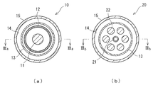
- the liquid heater 10 has a cylindrical shape as a whole, and a columnar near infrared heater 11 is placed at the center as shown in FIG.
- a path 12 a cylindrical reflecting plate 13, and a cylindrical outer protective tube 15 are arranged concentrically.
- the heating liquid channel 12 is formed by a gap between an outer tube and an inner tube having a double tube structure.
- the channel thickness (inside diameter / outside diameter difference) of the heating liquid channel 12 is desirably 1 to 5 mm.
- An air passage 14 through which air as a cooling medium is passed is secured between the reflector 13 and the external protective tube 15, and the air passage 14 corresponds to the cooling medium passage for cooling of the present invention.
- the heating liquid channel 12 has a ring shape in cross section, but a configuration in which a plurality of heating liquid channels are arranged on the circumference of the cross section is also possible.
- FIG.2 (b) shows the example of a change of the liquid heater 20, and the same code
- the liquid heater 20 has a cylindrical heating liquid channel 21 in the center by a cylindrical pipe line, and a plurality of columnar near infrared heaters 22 on the outer peripheral side of the heating liquid channel 21. Are arranged along the circumference.
- a cylindrical reflector 13 and a cylindrical external protective tube 15 are concentrically arranged in this order on the outer peripheral side of the circumference where the near infrared heater 22 is arranged.
- a large heater (when the liquid flow rate is large) requires a large number of heaters, and the heater may not be arranged in the center.
- the air passage 14 is secured between the reflecting plate 13 and the external protective tube 15.
- the width of the flow path is preferably 10 mm or less (more preferably 1 mm to 5 mm).
- the material of the reflection plate 13 for example, a quartz plate coated with gold can be used.
- Gold has an extremely high reflectance among various metals. However, if the temperature is too high, the vapor pressure increases and sublimates. Therefore, it is necessary to maintain an appropriate temperature. Metals other than gold can be used, but similar considerations are necessary.
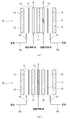
- FIG. 3A is an end view taken along line IIIa-IIIa through the near infrared heater 11 in FIG.
- the liquid heater 10 is arranged with the axial direction substantially up and down, and there is a gap penetrating vertically between the reflector 13 and the external protective tube 15, and the gap Is an air passage 14.
- an air nozzle 16 is disposed in the air passage 14 in the blowing direction, and an air passage 16 a is connected to the air nozzle 16.
- the space from the air flow path 16a, the air nozzle 16 and the air blowing portion of the air nozzle 16 to the ventilation path 14 constitutes the external cooling medium flow path of the present invention.
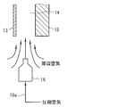
- the air nozzle 16 may be of a type that uses compressed air as power and entrains surrounding air to increase the air volume, as shown in FIG.
- the form is not limited as long as air is efficiently blown.
- the surrounding air is drawn from the outer peripheral side of the space between the air blowing portion of the air nozzle 16 and the air passage 14 by blowing the compressed air into the air passage 14, and the air passage 14.
- the reflector 13 is cooled in a large amount.
- the air that has cooled the reflecting plate 13 is discharged from the upper side of the air passage 14 to the surrounding space. Therefore, the space around the air nozzle 16 functions as an air intake portion of the present invention.
- a curtain or the like that communicates with the air passage 14 may be provided around the air nozzle 16 as an air intake portion so that air intake can be made more reliable.
- FIG. 3B is an end view taken along line IIIb-IIIb through the near infrared heater 11 in FIG.
- the liquid heater 20 is arranged with the axial direction substantially up and down, and there is a gap penetrating vertically between the reflector 13 and the external protective tube 15, and the gap serves as an air passage 14.
- an air nozzle 16 is disposed in the air passage 14 in the blowing direction, and an air passage 16 a is connected to the air nozzle 16.
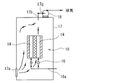
- FIG. 5 The example which installed the liquid heater 10 in the housing
- casing 17 is demonstrated based on FIG.
- the structure of the liquid heater 10 is simply described based on FIG. 3.
- a louver 17a is provided at a lower portion of the housing 17, an exhaust portion 17b is provided at an upper portion of the housing 17, and an exhaust fan 18 is connected to an exhaust passage 17c connected to the exhaust portion 17b.
- the housing 17 most of the cooling air is sucked from the gallery 17 a by the operation of the exhaust fan 18, and is discharged outside the housing 17 through the exhaust portion 17 b and the exhaust passage 17 c while passing through the housing 17.
- the exhaust passage 17c is made of a vinyl chloride resin tube, and the heat resistance (ordinary temperature) is up to 45 ° C. For this reason, it is necessary to reduce the exhaust temperature by sucking a large amount of air into the air passage 14 using an air intake portion that functions by the operation of the compressed air.
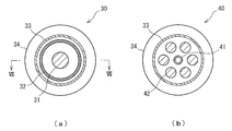
- the liquid heater 30 shown in FIG. 6A has a cylindrical near-infrared heater 31 at the center, and a ring-shaped heating liquid having a cross-sectional ring formed by a gap between the tubes of the double tube on the outer peripheral side thereof.
- the flow path 32, the cylindrical reflector 33, and the water-cooled jacket 34 having a ring-shaped cross section are arranged concentrically in this order.
- the water cooling jacket 34 is a passage through which cooling water flows, and corresponds to a cooling unit of the present invention.
- the reflector 33 and the water cooling jacket 34 may be manufactured separately and arranged so as to be in contact with each other, or a reflective material such as gold is plated inside the water cooling jacket 34 to form the reflector 33. May be.
- the reflecting plate 33 corresponds to the heat reflecting portion of the present invention.
- the liquid heater 40 shown in FIG. 6B shows a modification example of the water cooling method.
- symbol is attached
- the liquid heater 40 has a heating liquid channel 41 formed by a cylindrical pipe in the center, and a plurality of columnar near-infrared heaters 42 are arranged on the outer periphery side of the heating liquid channel 41. Arranged along the top. A cylindrical reflector 33 and a water cooling jacket 34 are concentrically arranged on the outer circumference side of the circumference where the near infrared heater 42 is arranged.
- FIG. 7 is an end view taken along line VII-VII through the near infrared heater 31 in FIG.
- a water cooling jacket 34 is disposed in close contact with the outer peripheral side of the reflector 33.
- the feed side of the external cooling water channel 35 is connected to the lower part of the water cooling jacket 34, and the return side of the external cooling water channel 35 is connected to the upper part of the water cooling jacket 34.
- the external cooling water channel 35 corresponds to the external cooling medium flow channel of the present invention.
- a cooling water tank 36 is provided in the external cooling water channel 35 and a pump 37 is provided downstream of the cooling water tank 36.
- the cooling water tank 36 is installed at a position higher than the liquid heater 30.
- a cooling water bypass path 38 that bypasses the pump 37 is provided in the external cooling water path 35 on the downstream side of the cooling water tank 36, and a valve 39 is provided in the cooling water bypass path 38.
- the valve 39 is closed when the cooling water normally flows through the external cooling water channel 35, and when the cooling water is not supplied to the water cooling jacket 34 due to a failure of the pump 37 or a power failure, or when the liquid feeding amount is abnormally reduced. open.
- the opening and closing of the valve 39 may be operated based on the amount and the water pressure of the cooling water flowing through the external cooling water channel 35, and can be operated by control by a control unit or the like. In the control by the control unit, it is possible to detect the amount of cooling water flowing through the external cooling water passage 35 and the like, and perform control based on the detection result. Further, in a normal energized state, a mechanism can be provided in which the valve 39 is closed and the valve is opened by an urging member or the like when the energization is interrupted unexpectedly due to a power failure. For example, a fail-open valve can be selected. it can.
- the valve 39 opens, and the cooling water whose temperature rises in the water cooling jacket 34 rises by buoyancy, and the cooling water can be circulated by natural circulation through the cooling water bypass path 38. .
- buoyancy can be increased by blowing air from the bottom of the water cooling jacket 34. Even if the supply of air is stopped, even if a part of the water in the water cooling jacket 34 boils, a large buoyancy works due to the boiling. Therefore, if there is water in the cooling water tank 36, it circulates. That is, the difference in water density between the descending side and the ascending side of the flow path is used. It is important that a sufficient amount of water is secured in the cooling water tank. In the above configuration, when the operation is continued, the temperature of the cooling water tank 36 increases, so that the cooling water can be received from the outside to the cooling water tank 36 and returned to the tank as needed.
- Air-water cooling method As a method that does not emit a large amount of exhaust as in the air-cooling method, and that does not have to worry about boiling when the utility is lost like water cooling, the air-water cooling method can be considered.
- the part that cools the liquid heater is the same as in the air cooling system, but the air that has become hot is cooled with cooling water and circulated for use. It is appropriate to use an air fin cooler as a device for efficiently cooling air.
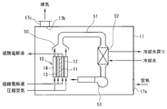
- This method is shown in FIG. In this embodiment, the liquid heater 10 will be described as an example.
- symbol is attached
- the liquid heater 10 is disposed in a housing 17 having a louver 17a, an exhaust port 17b, and an exhaust path 17c.
- a hood 50 is disposed above the liquid heater 10, and air released upward after passing through the air passage 14 is sucked.
- An external air passage 51 is connected to the hood 50, and an air fin cooler 52 is interposed in the external air passage 51.
- the air fin cooler 52 is supplied with cooling water and cools the air passing through the external air passage 51 with water.
- the external air passage 51 corresponds to the external cooling medium passage of the present invention, and the air fin cooler 52 corresponds to the second cooling section of the present invention.
- An air circulation fan 53 is connected to the downstream end of the external air passage 51.
- the air circulation fan 53 passes the external air passage 51, and the air cooled by the air fin cooler 52 is introduced to the air passage 14. Air is blown into the space. Thus, when the compressed air is introduced into the air passage 14, the air circulation fan 53 blows the air.
- the air circulation fan 53 corresponds to the air fan of the present invention. A large amount of the cooled air is taken into the air passage 14 to effectively cool the liquid heater 10, particularly the reflector 13.
- the heated air used for cooling in the liquid heater 10 is collected by the hood 50, cooled by the air fin cooler 52 through the external air passage 51, and then introduced to the air passage introduction side by the air circulation fan 53. Air-water cooling is performed continuously.
- Reflector temperature The reflector is a quartz plate coated with gold. The maximum use temperature of quartz is 1000 ° C., and gold sublimation (volatilization) does not become significant unless it exceeds 1000 ° C. Practically, if it is 800 degrees C or less, it is thought that there is no problem.
- External protective tube The material of the external protective tube is JIS SUS304 or ceramics. Therefore, there is no problem at 100 ° C. in terms of material. Since the radiant heat from the external protective tube to the housing is also radiation from 100 ° C., it is extremely small and does not cause a problem. 3. Exhaust temperature: below the normal temperature of the vinyl chloride resin tube, 45 ° C. From the above, it was found that long-term continuous operation is possible.
- Air-water cooling system The method of the present invention was carried out with the heater having the structure shown in FIG. 2B, the nozzle shown in FIG. 4, and the apparatus configuration shown in FIG.
- the implementation conditions and results were as follows.
- Comparative Example 1 As shown in FIGS. 11A and 11B, a liquid heater in which the outside of the reflecting plate was covered with a heat insulating material was used. As a heat insulating material, Gore-Tex (registered trademark) which is a kind of Teflon (registered trademark) was used. The configuration of the entire apparatus is as shown in FIG. Below, the structure of the liquid heater 60 of a comparative example is demonstrated easily. A near-infrared heater 61 is arranged at the center of the heating liquid flow path 62 formed by the gap between the tubes of the double pipe, and a reflection plate 63 is arranged on the outer peripheral side of the liquid flow path 62. A cylindrical heat insulating material 65 is disposed on the outer periphery to constitute a liquid heater 60, and the liquid heater 60 is accommodated in the casing 17 described above.
- Gore-Tex registered trademark
- Teflon registered trademark
- Condition Lamp input 18kW
- Thermal efficiency 50% (Efficiency calculated from temperature rise of sulfuric acid solution)
- Outside temperature 25 ° C
- Evaluation Materials with higher heat resistance must be used as insulation. Alternatively, the device needs to be cooled.
Landscapes
- Engineering & Computer Science (AREA)
- Physics & Mathematics (AREA)
- Thermal Sciences (AREA)
- Chemical & Material Sciences (AREA)
- Combustion & Propulsion (AREA)
- Mechanical Engineering (AREA)
- General Engineering & Computer Science (AREA)
- Heat-Pump Type And Storage Water Heaters (AREA)
- Resistance Heating (AREA)
- Instantaneous Water Boilers, Portable Hot-Water Supply Apparatuses, And Control Of Portable Hot-Water Supply Apparatuses (AREA)
Abstract
Description
加熱用液体流路100の外側に近赤外線ヒーター101が配置され、近赤外線ヒーター101の反対側に断熱材102が配置される。近赤外線ヒーター101から出力された熱線は加熱用液体流路100に向けて照射され、加熱用液体流路100を流れる硫酸電解液が輻射熱で急速に加熱され、高温の硫酸電解液が加熱用液体流路100から出液される。
前記冷却部は、前記熱反射部の反射面の裏面側に冷却媒体を通流して、前記熱反射部を前記冷却媒体によって冷却する冷却用冷却媒体流路を備えることを特徴とする。
第3の本発明の液体加熱器は、前記第1または第2の本発明において、前記加熱用液体流路が二重管で構成され、前記二重管の内管の内側に一または二以上の前記加熱部が配置され、前記二重管の外管の外側に前記熱反射部が配置され、さらに前記熱反射部の外側に前記冷却部が配置されていることを特徴とする。
第4の本発明の液体加熱器は、前記第1~第3の本発明のいずれかにおいて、前記冷却部は、前記冷却用冷却媒体流路に冷却媒体として空気を圧縮して吹き込む圧縮ポンプを備え、前記圧縮ポンプの吹き出し側と前記冷却用冷却媒体流路の入口側との間に、周囲の空気を取り込む空気取込部を有することを特徴とする。
第5の本発明の液体加熱器は、前記第4の本発明において、前記外部冷却媒体流路に、該外部冷却媒体流路で送られる空気を前記圧縮ポンプ側に向けて送風する空気ファンを備えることを特徴とする。
第6の本発明の液体加熱器は、前記第1~第3の本発明のいずれかにおいて、前記加熱用液体流路が液導入側を下方、液排出側を上方にして縦方向に沿って配置され、前記冷却用冷却媒体流路の液導入側に接続され、冷却媒体として液体を送るポンプが介設された外部冷却媒体流路を備え、さらに前記外部冷却媒体流路に、前記ポンプをバイパスする冷却媒体バイパス路を備え、該冷却媒体バイパス路に、前記外部冷却媒体流路での通常送液の間は閉となり、前記外部冷却媒体流路での送液停止または送液不良の間は開となるバルブを備えることを特徴とする。
第7の本発明の液体加熱器は、前記第1~第6の本発明のいずれかにおいて、前記加熱用液体が70~120℃であり、前記加熱用液体流路を通液する間に140~220℃の沸点未満まで昇温されるものであることを特徴とする。
第8の本発明の液体加熱器は、前記第1~第7の本発明のいずれかにおいて、前記加熱用液体流路の熱放射方向の厚みが10mm以下であることを特徴とする。
図1は、本発明の液体加熱器1を概念的に説明する図であり、以下に説明する。
液体加熱器1は、硫酸電解液を通液しつつ急速加熱して図示しない電子材料基板の洗浄に用いるものであり、硫酸電解液は、硫酸を電解して得られる。硫酸電解液は、65~96質量%の硫酸溶液を10~90℃の液温にして、少なくとも陽極をダイヤモンド電極とした電極間で電解して得られた後に90~120℃まで予備加熱されたものであり、液体加熱器1において急速(例えば0.5~10秒)、かつ高温(例えば140~220℃)に加熱して洗浄に供する。
(1)空冷は、冷却媒体として空気を用いる方式である。
(2)水冷は、冷却媒体として水を用いる方式である。
(3)空水冷は、冷却媒体として空気を用い、その空気を水で冷却して空気を循環使用する方式である。特徴は以下の通りである。
(2)水冷:装置がコンパクトで設置面積を小さくできるメリットがあるが、冷却水の供給が非常停止した時に冷却水が沸騰しないような工夫が必要である。
(3)空水冷:排気風量が小さく、ユーティリティ使用量の面で有利であり、かつ沸騰の心配も無いが、装置構成が複雑で設置面積が大きくなる。
このように利害得失があるので、状況に合わせて適切な方式を選ぶ必要がある。以下に、各冷却方式を採用した液体加熱器の例を説明する。
空冷方式の一実施形態の液体加熱器10を説明する。液体加熱器10は、全体が円筒形をしており、図2(a)に示すように中心部に円柱状の近赤外線ヒーター11を置き、順に外に向かって断面リング状の加熱用液体流路12、円筒状の反射板13、円筒状の外部保護管15が同心状に配置されている。
加熱用液体流路12は、二重管構造からなる外管および内管同士の間隙によって形成されている。加熱用液体流路12の流路厚み(内径外径差)は望ましくは1~5mmとされる。
反射板13と外部保護管15の間は、冷却媒体としての空気を通風する通気路14が確保されており、通気路14は本発明の冷却用冷却媒体流路に相当し、本発明の冷却部の一部を構成している。なお、この形態では加熱用液体流路12を断面リング状としたが、断面円周上に複数の加熱用液体流路が配置された構成とすることも可能である。
液体加熱器20は、円筒の管路によって中心部に円柱状の加熱用液体流路21を有しており、該加熱用液体流路21の外周側に、複数の円柱状の近赤外線ヒーター22が円周上に沿って配置されている。該近赤外線ヒーター22が配置された円周の外周側に円筒状の反射板13、円筒状の外部保護管15がこの順に同心状に配置されている。大型の加熱器(液流量が多い場合)では、ヒーター本数を多く必要とし、中心部にヒーター配置できないことがある。このような場合には、図2(b)のように、加熱用液体流路21の外周側にヒーターを配置するのが効果的である。
この形態においても、反射板13と外部保護管15との間に通気路14が確保されている。なお、円柱状の加熱用液体流路21では、外周から均等に加熱されているため、その流路幅を10mm以下(さらに望ましくは1mm~5mm)とするのが望ましい。
圧縮空気を利用する形態では、圧縮空気の通気路14内への吹き込みによって、空気ノズル16の空気吹き出し部分と通気路14との間にある空間外周側から周囲の空気が引き込まれて通気路14内に大量に導入され、反射板13が冷却される。反射板13を冷却した空気は、通気路14の上方側から周囲空間に排出される。したがって、空気ノズル16の周囲空間は本発明の空気取込部として機能する。なお、空気ノズル16の周囲に通気路14に連通するカーテンなどを空気取込部として設け、空気の取り込みをより確実にするように構成してもよい。
液体加熱器20は軸方向を略上下にして配置されており、反射板13と外部保護管15の間には上下に貫通する隙間を有し、該隙間が通気路14となっている。通気路14の下部の導入側には、通気路14内を吹き出し方向とする空気ノズル16が配置されており、該空気ノズル16に空気流路16aが接続されている。
筺体17の下方部にはガラリ17aが設けられ、筺体17の上方部に排気部17bが設けられており、排気部17bに接続した排気路17cに排気ファン18が接続されている。これにより、筺体17内では、排気ファン18の動作によって冷却用空気の大半はガラリ17aから吸い込まれ、筺体17内を通過しつつ、排気部17b、排気路17cを通して筺体17外に排出される。この空気を反射板13と外部保護管15との間の通気路14に通すための動力として上記のように圧縮空気を用いるのが望ましい。通常、排気路17cは塩化ビニール樹脂管でできており、耐熱性(常用温度)は45℃までである。このため、圧縮空気の動作によって機能する空気取込部を利用して通気路14に大量の空気を吸い込んで排気温度を下げる必要がある。
次に、冷却部を水冷方式とした液体加熱器について図6(a)、(b)および図7に基づいて説明する。
図6(a)に示す液体加熱器30では、中心部に円柱状の近赤外線ヒーター31を有し、その外周側に二重管の管同士の隙間によって形成された断面リング状の加熱用液体流路32、円筒状の反射板33、断面リング状の水冷ジャケット34をこの順にして同心状に配置されている。水冷ジャケット34は、冷却水が通水されるものであり、本発明の冷却部に相当する。なお、反射板33と水冷ジャケット34を個別に製作し、両者が接するように配置しても良いし、水冷ジャケット34の内側に反射性物質、例えば金などをメッキして反射板33を構成してもよい。反射板33は、本発明の熱反射部に相当する。
液体加熱器40は、中心部に円筒管路によって形成された加熱用液体流路41を有し、該加熱用液体流路41の外周側に、複数の円柱状の近赤外線ヒーター42が円周上に沿って配置されている。該近赤外線ヒーター42が配置された円周の外周側に円筒状の反射板33、水冷ジャケット34が同心状に配置されている。
そこで、例えば図8に示すような安全機構を備える構成にすることが考えられる。図8では、液体加熱器30の構成を簡略に示している。
上記構成では、運転を継続すると冷却水槽36の温度が上昇するので、随時冷却水を外部から冷却水槽36に受け入れ、また返送することにより一定温度を保つことができる。
空冷方式のように大量の排気を出さず、また、水冷のようにユーティリティ喪失時の沸騰の心配をしなくて良い方法として、空水冷方式が考えられる。
液体加熱器を冷却する部分は、空冷方式と同じであるが、高温になった空気を冷却水で冷やして循環使用するのである。空気を効率良く冷やす装置としてエアフィンクーラーを使用するのが妥当である。この方式を図9に示す。この実施形態では、液体加熱器10を例にして説明する。なお、前記実施形態と同様の構成については同一の符号を付して説明する。また、図9では、液体加熱器10の構成を簡略に示している。
液体加熱器10の上方には、フード50が配置され、通気路14を通過した上方に放出された空気が吸引される。フード50には、外部空気路51が接続され、外部空気路51には、エアフィンクーラー52が介設されている。エアフィンクーラー52は、冷却水が供給されており、外部空気路51を通る空気を水冷する。上記外部空気路51は、本発明の外部冷却媒体流路に相当し、エアフィンクーラー52は、本発明の第2冷却部に相当する。
これにより、通気路14に圧縮空気を導入する際に、空気循環ファン53で送風される。空気循環ファン53は、本発明の空気ファンに相当する。冷却された空気が通気路14内に大量に取り込まれ、液体加熱器10内、特に反射板13を効果的に冷却する。液体加熱器10内で冷却に用いられ、昇温した空気は、フード50で回収され、外部空気路51を通ってエアフィンクーラー52で冷却された後、空気循環ファン53で通気路導入側に供給されて、空水冷が継続して行われる。
発明例:
(1)空冷方式
図2(b)および図3(b)に示す構造の加熱器、図4に示すノズル、図5に示す装置構成で、本発明の方法を実施した。実施条件と結果は以下の通りであった。
条件
ランプ入力:18kW
熱効率:50% (硫酸溶液の温度上昇から計算される効率)
冷却負荷:9kW (= 18kW×(100-50)/100)
圧縮空気流量:500NL/min
筐体外温度:25℃
排気風量:25m3/min
結果
反射板温度=500℃
外部保護管温度=100℃
排気温度=44℃
1.反射板温度:反射板は石英板に金をコーティングしたものである。石英の最高使用温度は1000℃であり、金の昇華(揮散)は1000℃を超えなければ顕著にならない。実用的には800℃以下であれば問題ないと考えられる。
2.外部保護管:外部保護管の材質はJIS SUS304またはセラミックスである。よって、100℃は材質的には全く問題ない。外部保護管から筐体への輻射熱も100℃からの輻射であるので、極僅かであり、問題とならない。
3.排気温度:塩化ビニール樹脂管の常用温度45℃を下回る。
以上より、長期連続運転が可能であることが分かった。
図6(a)および図7に示す構造の加熱器、図8に示す装置構成で、本発明の方法を実施した。実施条件と結果は以下の通りであった。
ランプ入力:12kW
熱効率:60% (硫酸溶液の温度上昇から計算される効率)
冷却負荷:4.8kW (=12kW×(100-60)/100 )
冷却水入口温度:25℃
冷却水戻り温度:35℃
結果
反射板表面温度=100℃
冷却水流量=6.9L/min
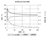
定常運転状態からランプを消灯すると同時に水冷ポンプを停止したところ、バルブが開いて水の自然循環が始まった。この時、冷却水槽の保有水量は20Lであった。温度変化を計測したところ、図10のようになった。ポンプ停止後約5分間は、水冷ジャケット出口水は沸騰状態であった。しかし、その後温度が下がり、約70℃になった。また、冷却水槽温度は徐々に上がり、3時間後には約65℃になった。
1.反射板温度:反射板は直接水冷ジャケットに接しているので温度が低く、表面で100℃であった。装置上の問題無し。
2.冷却水流量:6.9L/minは枚葉式洗浄機1台にとって大きな流量ではない。
3.保有水量が20Lあれば、ポンプが停止しても冷却水系統全体が沸騰することは無く、安全に停止できることが分かった。
以上より、長期連続運転が可能であること、および冷却水ポンプが停止しても安全に装置全体が停止できることが分かった。
図2(b)に示す構造の加熱器、図4に示すノズル、図9に示す装置構成で、本発明の方法を実施した。実施条件と結果は以下の通りであった。
ランプ入力:18kW
熱効率:50% (硫酸溶液の温度上昇から計算される効率)
冷却負荷:9kW (=18kW×(100-50)/100)
圧縮空気流量:500NL/min
筐体外温度:25℃
排気風量:2m3/min
冷却水入口温度:25℃
冷却水戻り温度:35℃
反射板温度=500℃
外部保護管温度=100℃
排気温度=40℃
冷却水流量=12.2L/min
1.反射板温度:空冷方式に同じ。
2.外部保護管:空冷方式に同じ。
3.排気温度:塩化ビニール樹脂管の常用温度45℃を下回る。
4.冷却水量:枚葉式洗浄機1台の使用量として、妥当な量である。
以上より、妥当なユーティリティ使用量で長期連続運転が可能であることが分かった。
(1)比較例1
図11(a)(b)に示すように、反射板の外側を断熱材で覆った液体加熱器を用いた。断熱材は、テフロン(登録商標)の一種であるゴアテックス(登録商標)を用いた。装置全体の構成は図12に示す通りである。
以下に、比較例の液体加熱器60の構造を簡略に説明する。
二重管の管同士の隙間で形成した加熱用液体流路62の中心部に、近赤外線ヒーター61を配置し、液体流路62の外周側に、反射板63が配置され、反射板63の外周に、筒状の断熱材65が配置されて、液体加熱器60が構成されており、該液体加熱器60は、前記した筺体17内に収納されている。
条件
ランプ入力:18kW
熱効率:50% (硫酸溶液の温度上昇から計算される効率)
冷却負荷:9kW (=18kW×(100-50)/100)
筐体外温度:25℃
定常状態に至る前に、ゴアテックス(登録商標)が溶損して煙が発生した。テフロン(登録商標)の耐熱温度は260℃であるが、これをはるかに超えたものと推定される。
耐熱温度がもっと高い材料を断熱材としなければならない。あるいは装置を冷却する必要がある。
比較例1と同様の液体加熱器を用い、断熱材を高温に耐える石英ウールに交換した。
条件
比較例1に同じ。
結果
石英ウールを輻射熱線が透過し、石英ウールを固定する鋼板製の外筒(図示せず。)が過熱し、鋼板に塗った塗料(テフロン(登録商標)コーティング)から発煙した。よって、テフロン(登録商標)の耐熱温度をはるかに超える温度に達したものと推定される。
例え、極めて高温に耐える断熱材を用いたとしても、熱が装置内にこもれば温度が上昇する。よって、断熱材の種類に拘わらず、流体に吸収されなかった熱線に相当するエネルギーを除去するために装置を冷却する必要があり、現実的でない。
2 加熱用液体流路
3 近赤外線ヒーター
4 反射板
5 冷却部
10 液体加熱器
11 近赤外線ヒーター
12 加熱用液体流路
13 反射板
14 通気路
15 外部保護管
20 液体加熱器
21 加熱用液体流路
22 近赤外線ヒーター
30 液体加熱器
31 近赤外線ヒーター
32 加熱用液体流路
33 反射板
34 水冷ジャケット
35 外部冷却水路
36 冷却水槽
38 冷却水バイパス路
39 バルブ
40 液体加熱器
41 加熱用液体流路
42 近赤外線ヒーター
Claims (8)
- 加熱用液体が通液される加熱用液体流路と、前記加熱用液体流路の一側に配置され、熱放射方向が前記通液の方向に交差するように前記加熱用液体流路に向けて熱放射が可能な加熱部と、前記加熱用液体流路の他側に配置される熱反射部と、前記熱反射部を冷却する冷却部と、を備え、
前記冷却部は、前記熱反射部の反射面の裏面側に冷却媒体を通流して、前記熱反射部を前記冷却媒体によって冷却する冷却用冷却媒体流路を備えることを特徴とする液体加熱器。 - 前記冷却用冷却媒体流路の導入側と排出側とにそれぞれ外部冷却媒体流路が接続され、前記排出側の前記外部冷却媒体流路に前記冷却媒体を冷却する第2冷却部が介設されていることを特徴とする請求項1記載の液体加熱器。
- 前記加熱用液体流路が二重管で構成され、前記二重管の内管の内側に一または二以上の前記加熱部が配置され、前記二重管の外管の外側に前記熱反射部が配置され、さらに前記熱反射部の外側に前記冷却部が配置されていることを特徴とする請求項1または2に記載の液体加熱器。
- 前記冷却部は、前記冷却用冷却媒体流路に冷却媒体として空気を圧縮して吹き込む圧縮ポンプを備え、前記圧縮ポンプの吹き出し側と前記冷却用冷却媒体流路の入口側との間に、周囲の空気を取り込む空気取込部を有することを特徴とする請求項1~3のいずれかに記載の液体加熱器。
- 前記外部冷却媒体流路に、該外部冷却媒体流路で送られる空気を前記圧縮ポンプ側に向けて送風する空気ファンを備えることを特徴とする請求項4記載の液体加熱器。
- 前記加熱用液体流路が液導入側を下方、液排出側を上方にして縦方向に沿って配置され、前記冷却用冷却媒体流路の液導入側に接続され、冷却媒体として液体を送るポンプが介設された外部冷却媒体流路を備え、
さらに前記外部冷却媒体流路に、前記ポンプをバイパスする冷却媒体バイパス路を備え、該冷却媒体バイパス路に、前記外部冷却媒体流路での通常送液の間は閉となり、前記外部冷却媒体流路での送液停止または送液不良の間は開となるバルブを備えることを特徴とする請求項1~3のいずれかに記載の液体加熱器。 - 前記加熱用液体が70~120℃であり、前記加熱用液体流路を通液する間に140~220℃の沸点未満まで昇温されるものであることを特徴とする請求項1~6のいずれかに記載の液体加熱器。
- 前記加熱用液体流路の熱放射方向の厚みが10mm以下であることを特徴とする請求項1~7のいずれかに記載の液体加熱器。
Priority Applications (4)
| Application Number | Priority Date | Filing Date | Title |
|---|---|---|---|
| KR1020137026101A KR20140016317A (ko) | 2011-05-26 | 2012-05-24 | 액체 가열기 |
| CN201280025410.0A CN103562649B (zh) | 2011-05-26 | 2012-05-24 | 液体加热器 |
| US14/088,693 US9791169B2 (en) | 2011-05-26 | 2012-05-24 | Liquid heater |
| TW101118711A TWI474421B (zh) | 2011-05-26 | 2012-05-25 | 液體加熱器 |
Applications Claiming Priority (2)
| Application Number | Priority Date | Filing Date | Title |
|---|---|---|---|
| JP2011117764A JP5812258B2 (ja) | 2011-05-26 | 2011-05-26 | 液体加熱器 |
| JP2011-117764 | 2011-05-26 |
Publications (1)
| Publication Number | Publication Date |
|---|---|
| WO2012161247A1 true WO2012161247A1 (ja) | 2012-11-29 |
Family
ID=47217320
Family Applications (1)
| Application Number | Title | Priority Date | Filing Date |
|---|---|---|---|
| PCT/JP2012/063272 Ceased WO2012161247A1 (ja) | 2011-05-26 | 2012-05-24 | 液体加熱器 |
Country Status (6)
| Country | Link |
|---|---|
| US (1) | US9791169B2 (ja) |
| JP (1) | JP5812258B2 (ja) |
| KR (1) | KR20140016317A (ja) |
| CN (1) | CN103562649B (ja) |
| TW (1) | TWI474421B (ja) |
| WO (1) | WO2012161247A1 (ja) |
Cited By (1)
| Publication number | Priority date | Publication date | Assignee | Title |
|---|---|---|---|---|
| CN111780455A (zh) * | 2020-06-12 | 2020-10-16 | 樊晓东 | 一种机体温度的调控方法 |
Citations (1)
| Publication number | Priority date | Publication date | Assignee | Title |
|---|---|---|---|---|
| US5054107A (en) * | 1989-05-19 | 1991-10-01 | Geoffrey Batchelder | Radiating lamp fluid heating system |
Family Cites Families (8)
| Publication number | Priority date | Publication date | Assignee | Title |
|---|---|---|---|---|
| JPS6288390A (ja) | 1985-10-15 | 1987-04-22 | Nec Corp | 半導体レ−ザ |
| JPS6288390U (ja) * | 1985-11-22 | 1987-06-05 | ||
| US5054108A (en) * | 1987-03-30 | 1991-10-01 | Arnold Gustin | Heater and method for deionized water and other liquids |
| DE19613411C1 (de) * | 1996-04-03 | 1997-08-21 | Steag Micro Tech Gmbh | Fluid-Heizeinrichtung mit einem von einem Fluid durchströmten Rohr |
| JP2005228237A (ja) | 2004-02-16 | 2005-08-25 | Hitachi Ltd | 液冷システム及びそれを備えた電子機器 |
| CN2752676Y (zh) * | 2004-12-22 | 2006-01-18 | 许秀贤 | 红外线加热器 |
| JP5610679B2 (ja) | 2008-09-01 | 2014-10-22 | 栗田工業株式会社 | 液体加熱器および液体加熱方法 |
| CN102147148A (zh) * | 2010-02-08 | 2011-08-10 | 清华大学 | 流体加热器及其使用方法 |
-
2011
- 2011-05-26 JP JP2011117764A patent/JP5812258B2/ja not_active Expired - Fee Related
-
2012
- 2012-05-24 US US14/088,693 patent/US9791169B2/en not_active Expired - Fee Related
- 2012-05-24 CN CN201280025410.0A patent/CN103562649B/zh active Active
- 2012-05-24 WO PCT/JP2012/063272 patent/WO2012161247A1/ja not_active Ceased
- 2012-05-24 KR KR1020137026101A patent/KR20140016317A/ko not_active Ceased
- 2012-05-25 TW TW101118711A patent/TWI474421B/zh not_active IP Right Cessation
Patent Citations (1)
| Publication number | Priority date | Publication date | Assignee | Title |
|---|---|---|---|---|
| US5054107A (en) * | 1989-05-19 | 1991-10-01 | Geoffrey Batchelder | Radiating lamp fluid heating system |
Cited By (1)
| Publication number | Priority date | Publication date | Assignee | Title |
|---|---|---|---|---|
| CN111780455A (zh) * | 2020-06-12 | 2020-10-16 | 樊晓东 | 一种机体温度的调控方法 |
Also Published As
| Publication number | Publication date |
|---|---|
| US20140079377A1 (en) | 2014-03-20 |
| JP5812258B2 (ja) | 2015-11-11 |
| JP2012247096A (ja) | 2012-12-13 |
| US9791169B2 (en) | 2017-10-17 |
| KR20140016317A (ko) | 2014-02-07 |
| TWI474421B (zh) | 2015-02-21 |
| TW201308484A (zh) | 2013-02-16 |
| CN103562649B (zh) | 2016-08-17 |
| CN103562649A (zh) | 2014-02-05 |
Similar Documents
| Publication | Publication Date | Title |
|---|---|---|
| US6621984B2 (en) | In-line fluid heating system | |
| KR100769694B1 (ko) | 물을 이용한 매트의 냉온수순환장치 | |
| KR101007960B1 (ko) | 적외선 방출 소자 | |
| JP5812258B2 (ja) | 液体加熱器 | |
| JP6043635B2 (ja) | 熱源機 | |
| CN104214932A (zh) | 水冷预热式加热体 | |
| KR20090006918A (ko) | 열매체유를 이용한 축열전기보일러 | |
| CN208459125U (zh) | 一种用于小试件快速热处理的聚光式红外辐射加热器 | |
| RU137092U1 (ru) | Модуль для электрического нагрева жидкостных сред (варианты) | |
| JP3033047B2 (ja) | 流体の温度制御装置 | |
| KR100767806B1 (ko) | 변류돌기를 구비한 가열로, 냉각로 및 롤러하스형 소둔로 | |
| CN206056316U (zh) | 一种耐高温玻璃熔炼炉水冷供电装置 | |
| US11957802B2 (en) | Fluid sterilization apparatus and fluid sterilization system | |
| KR100747743B1 (ko) | 와류방지가이드를 구비한 가열로와 냉각로 및 롤러하스형소둔로 | |
| JPH0685395B2 (ja) | 半導体製造装置等における加熱装置 | |
| KR20060008548A (ko) | 쿡탑용 복사 히터의 냉각 장치 | |
| KR200311734Y1 (ko) | 선형 근적외선 히터 모듈 | |
| CN207006514U (zh) | 一种循环水冷式电磁热水器 | |
| JP2020020555A (ja) | 高温水製造装置 | |
| CN222912382U (zh) | 一种冷却结构及预氧化炉火焰检测装置 | |
| CN105810534A (zh) | 一种微波干燥设备的磁控管用水冷散热装置 | |
| CN221449757U (zh) | 一种牛筋面生产中的能量恒温保护装置 | |
| CN210831891U (zh) | 一种循环水冷式防水光束灯 | |
| CN213334950U (zh) | 一种高效的导热油电加热器 | |
| CN216523027U (zh) | 具有循环冷却功能的辊道炉 |
Legal Events
| Date | Code | Title | Description |
|---|---|---|---|
| 121 | Ep: the epo has been informed by wipo that ep was designated in this application |
Ref document number: 12788796 Country of ref document: EP Kind code of ref document: A1 |
|
| ENP | Entry into the national phase |
Ref document number: 20137026101 Country of ref document: KR Kind code of ref document: A |
|
| WWE | Wipo information: entry into national phase |
Ref document number: 14088693 Country of ref document: US |
|
| NENP | Non-entry into the national phase |
Ref country code: DE |
|
| 122 | Ep: pct application non-entry in european phase |
Ref document number: 12788796 Country of ref document: EP Kind code of ref document: A1 |