WO2012161222A1 - 導光板、面光源装置及び透過型画像表示装置 - Google Patents
導光板、面光源装置及び透過型画像表示装置 Download PDFInfo
- Publication number
- WO2012161222A1 WO2012161222A1 PCT/JP2012/063200 JP2012063200W WO2012161222A1 WO 2012161222 A1 WO2012161222 A1 WO 2012161222A1 JP 2012063200 W JP2012063200 W JP 2012063200W WO 2012161222 A1 WO2012161222 A1 WO 2012161222A1
- Authority
- WO
- WIPO (PCT)
- Prior art keywords
- guide plate
- light guide
- layer
- light
- plate base
- Prior art date
- Legal status (The legal status is an assumption and is not a legal conclusion. Google has not performed a legal analysis and makes no representation as to the accuracy of the status listed.)
- Ceased
Links
Images



Classifications
-
- G—PHYSICS
- G02—OPTICS
- G02B—OPTICAL ELEMENTS, SYSTEMS OR APPARATUS
- G02B6/00—Light guides; Structural details of arrangements comprising light guides and other optical elements, e.g. couplings
- G02B6/0001—Light guides; Structural details of arrangements comprising light guides and other optical elements, e.g. couplings specially adapted for lighting devices or systems
- G02B6/0011—Light guides; Structural details of arrangements comprising light guides and other optical elements, e.g. couplings specially adapted for lighting devices or systems the light guides being planar or of plate-like form
- G02B6/0033—Means for improving the coupling-out of light from the light guide
- G02B6/0058—Means for improving the coupling-out of light from the light guide varying in density, size, shape or depth along the light guide
- G02B6/0061—Means for improving the coupling-out of light from the light guide varying in density, size, shape or depth along the light guide to provide homogeneous light output intensity
-
- G—PHYSICS
- G02—OPTICS
- G02B—OPTICAL ELEMENTS, SYSTEMS OR APPARATUS
- G02B6/00—Light guides; Structural details of arrangements comprising light guides and other optical elements, e.g. couplings
- G02B6/0001—Light guides; Structural details of arrangements comprising light guides and other optical elements, e.g. couplings specially adapted for lighting devices or systems
- G02B6/0011—Light guides; Structural details of arrangements comprising light guides and other optical elements, e.g. couplings specially adapted for lighting devices or systems the light guides being planar or of plate-like form
- G02B6/0033—Means for improving the coupling-out of light from the light guide
- G02B6/0035—Means for improving the coupling-out of light from the light guide provided on the surface of the light guide or in the bulk of it
-
- G—PHYSICS
- G02—OPTICS
- G02B—OPTICAL ELEMENTS, SYSTEMS OR APPARATUS
- G02B6/00—Light guides; Structural details of arrangements comprising light guides and other optical elements, e.g. couplings
- G02B6/0001—Light guides; Structural details of arrangements comprising light guides and other optical elements, e.g. couplings specially adapted for lighting devices or systems
- G02B6/0011—Light guides; Structural details of arrangements comprising light guides and other optical elements, e.g. couplings specially adapted for lighting devices or systems the light guides being planar or of plate-like form
- G02B6/0065—Manufacturing aspects; Material aspects
-
- G—PHYSICS
- G02—OPTICS
- G02B—OPTICAL ELEMENTS, SYSTEMS OR APPARATUS
- G02B6/00—Light guides; Structural details of arrangements comprising light guides and other optical elements, e.g. couplings
- G02B6/0001—Light guides; Structural details of arrangements comprising light guides and other optical elements, e.g. couplings specially adapted for lighting devices or systems
- G02B6/0011—Light guides; Structural details of arrangements comprising light guides and other optical elements, e.g. couplings specially adapted for lighting devices or systems the light guides being planar or of plate-like form
- G02B6/0033—Means for improving the coupling-out of light from the light guide
- G02B6/005—Means for improving the coupling-out of light from the light guide provided by one optical element, or plurality thereof, placed on the light output side of the light guide
- G02B6/0055—Reflecting element, sheet or layer
Definitions
- the present invention relates to a light guide plate, a surface light source device, and a transmissive image display device.
- a transmissive image display device such as a liquid crystal display device generally has a surface light source device as a backlight.
- a surface light source device As a method of the surface light source device, there are a direct type in which a light source is provided on the back side of the light guide plate and an edge light method in which a light source is provided along the side surface of the light guide plate.
- the edge light system is advantageous from the viewpoint of reducing the thickness of the image display device. Development of a high-luminance and large-sized surface light source device by an edge light method is strongly desired.
- Patent Document 1 Japanese Unexamined Patent Application Publication No. 2007-204536 discloses that a styrene resin molded into a plate shape is used as a light guide plate.
- Patent Document 2 Japanese Patent Laid-Open No. 9-020860
- Patent Document 3 Japanese Patent Laid-Open No. 11-158364 disclose that a polycarbonate resin molded into a plate shape is used as a light guide plate.
- JP 2007-204536 A JP-A-9-020860 JP-A-11-158364
- the entire light guide plate base material is yellowish, which may affect the image display of the light guide plate.
- a bluing agent to a styrenic resin and form it into a plate shape to form a light guide plate base material.
- the bluing agent is uniformly contained in the light guide plate base material, the yellowness of the entire light guide plate base material is suppressed, while the light transmittance tends to decrease.
- the present invention has been made in view of the above circumstances, and includes a light guide plate that includes a styrene-based resin or a polycarbonate resin, suppresses yellowness and suppresses a decrease in light transmittance, and the light guide plate.
- An object of the present invention is to provide a planar light source device and a transmissive image display device.
- the present invention is provided on the back side of the light guide plate base material portion having a light exit surface that emits light and a back surface opposite to the light exit surface, and reflects light to the light output surface side.
- the light guide plate base material part is a multilayer body in which at least one first layer and at least one second layer are laminated, and each of the first layer and the second layer is made of styrene.
- a light guide plate that contains a resin or a polycarbonate resin, wherein the content of the bluing agent in the first layer is 0.1 ppm to 10 ppm, and the content of the bluing agent in the second layer is less than 0.1 ppm .
- the light guide plate is made of styrene resin or polycarbonate resin. In the light guide plate, yellowness can be suppressed and a decrease in light transmittance can be suppressed.
- the present invention has a styrene monomer unit content of 50% by mass to 100% by mass, and a (meth) acrylic acid ester unit content. Is preferably applied in the case of 0 mass% to 50 mass%.
- d 1 / d satisfies 0.01 to 0.05, where d is the thickness of the light guide plate base material portion and d 1 is the thickness of the first layer.
- the outermost layer on the light exit surface side of the light guide plate base portion is the first layer.
- the outermost layer on the back side of the light guide plate base material portion is the first layer.
- the present invention provides a surface light source device including the light guide plate and a light source unit that supplies light to the side surface of the light guide plate base material.
- the present invention provides the light guide plate, the light source unit that supplies light to the side surface of the light guide plate base member, and the transmission surface that is provided on the light exit surface side of the light guide plate base member and is illuminated with light emitted from the light exit surface.
- a transmissive image display device comprising a mold image display unit is provided.
- a light guide plate using a styrene-based resin or a polycarbonate resin, the light guide plate that suppresses yellowness and suppresses a decrease in light transmittance, and a surface light source including the light guide plate An apparatus and a transmissive image display device can be provided.
- FIG. 1 is an end view showing an embodiment of a transmissive image display apparatus.
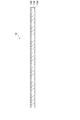
- FIG. 2 is a cross-sectional view showing an embodiment of the light guide plate base material portion according to this embodiment.
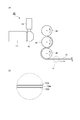
- FIG. 3 is a schematic diagram showing one process of manufacturing the light guide plate according to the present embodiment.
- FIG. 4 is a cross-sectional view showing another embodiment of the light guide plate substrate portion according to this embodiment.
- FIG. 5 is a schematic view showing a method for measuring the total light transmittance in Examples.
- the transmissive image display device 10 of FIG. 1 includes a surface light source device 22 having a light guide plate 11 and a transmissive image display portion 18 provided on the light exit surface 12b side of the light guide plate base material portion 12 of the light guide plate 11.
- the arrangement direction of the surface light source device 22 and the transmissive image display unit 18 is referred to as the z direction, which is two directions orthogonal to the z direction and two directions orthogonal to each other. Are referred to as x-direction and y-direction, respectively.
- the transmissive image display device 10 displays an image by illuminating the transmissive image display unit 18 with light emitted from the surface light source device 22.
- An example of the transmissive image display unit 18 is a liquid crystal display panel.
- the transmissive image display device 10 is a liquid crystal display device (or a liquid crystal television).
- the transmissive image display device 10 may further include a plurality of optical films 20 disposed between the light guide plate 11 and the transmissive image display unit 18.
- the optical film 20 are a diffusion film, a prism film, and a brightness enhancement film.
- the surface light source device 22 includes an edge light type surface light source device including a light guide plate 11 having a plate-shaped light guide plate base material portion 12 and a light source portion 14 disposed in the vicinity of a side surface 12 a of the light guide plate base material portion 12. 22.
- the surface light source device 22 may further include a reflection sheet 16 disposed on the back surface 12 c side of the light guide plate base material portion 12. By providing the reflection sheet 16, the light emitted from the light guide plate 11 toward the reflection sheet 16 can be returned to the light guide plate 11. As a result, the light from the light source unit 14 can be used more effectively.
- the optical film 20 may be a component of the surface light source device 22.
- the light source unit 14 includes a light source 14A.
- the light source 14 ⁇ / b> A is provided along the y direction of the side surface 12 a of the light guide plate base material portion 12.
- the side surface 12a is an incident surface.
- the light source 14A may be a point light source such as a light emitting diode, a halogen lamp, and a tungsten lamp, or may be a linear light source such as a fluorescent tube.
- An RGB type light emitting diode that emits red light, green light, and blue light is suitably used as the light source 14A.
- the distance between the light source 14A and the side surface (incident surface) 12a of the light guide plate base 12 is usually 1 mm to 15 mm, preferably 10 mm or less, more preferably 5 mm or less.
- the light source 14A is a point light source
- a plurality of point light sources are linearly arranged along the y direction of the side surface 12a.
- the interval between adjacent point light sources is usually 1 mm to 25 mm. From the viewpoint of power saving, the distance between adjacent point light sources is preferably 10 mm or more so that the number of point light sources can be reduced.
- the light source unit 14 may further include a reflector 14B that is provided on the side opposite to the light guide plate 11 and reflects light. By having the reflector 14B, the light from the light source 14A can be efficiently incident on the side surface 12a of the light guide plate base 12.
- the reflector 14B is formed from, for example, a white resin plate or a white resin film.
- the light source unit 14 is provided on only one side surface among the four side surfaces of the light guide plate substrate unit 12.
- the light source part 14 should just be provided in the side of the light-guide plate base-material part 12.
- the light source unit 14 may be provided for each of the pair of opposing side surfaces of the light guide plate base member 12, or may be provided on all four side surfaces that intersect the emission surface 12 b and the back surface 12 c (orthogonal in FIG. 1).
- the light source unit 14 may be provided.
- the light guide plate 11 has a light guide plate base material portion 12 and a reflection portion 24 provided on the back surface 12 c of the light guide plate base material portion 12.
- the light guide plate base material portion 12 is a plate-like body having a substantially rectangular shape in plan view when viewed from the z direction.
- the light guide plate base 12 has an exit surface 12b that emits light and a back surface 12c opposite to the exit surface 12b.
- the thickness of the light guide plate base 12 is preferably 1 mm to 30 mm, more preferably 1 mm to 10 mm.
- the side surface 12a of the light guide plate substrate portion 12 is preferably smoothed by a polishing process or the like.
- the light guide plate base material portion 12 can be produced by a method that is usually employed as a method for molding a resin plate.
- the light guide plate base material portion 12 can be manufactured by a hot press method, a melt extrusion method, an injection molding method, or the like.
- the reflection part 24 is provided on the back surface 12c side of the light guide plate base part 12.
- the reflection part 24 reflects the light that has reached the back surface 12c of the light guide plate base material part 12 to the emission surface 12b side.
- An example of the reflection unit 24 is a diffusion dot.
- the diffusion dots reflect the light propagating toward the back surface 12c while diffusing the light toward the exit surface 12b.
- the diffusing dots are typically white dots.
- the diffusion dots are formed in a pattern designed to make the emitted light uniform.
- the diffusing dots can be formed by, for example, screen printing or ink jet printing.
- the reflection part 24 is not limited to the diffusing dots.
- an uneven shape having a predetermined pattern may be formed on the back surface 12 c, and the back surface 12 c having the uneven shape may be the reflecting portion 24.
- lens-shaped transparent or semi-transparent dots may be provided on the back surface 12 c as the reflection part 24. The traveling direction of the light is changed by the effect of the lens, and the light can be emitted from the emission surface 12b.
- the light guide plate base 12 is a laminated body (multilayer body) in which the first layer 12d and the second layer 12e are laminated in the order of the first layer 12d, the second layer 12e, and the first layer 12d. That is, the light guide plate base material portion 12 has a two-type three-layer structure in which the second layer 12e that is an intermediate layer is sandwiched between the first layers 12d that are surface layers.
- the first layer 12d and the second layer 12e are layers made of styrene resin.
- An example of the styrenic resin is polystyrene.
- the content of the bluing agent in the first layer 12d is 0.1 ppm to 10 ppm, preferably 0.1 ppm to 1 ppm, based on the mass of the first layer 12d.
- the content of the bluing agent in the second layer 12e is less than 0.1 ppm, preferably 0.07 ppm or less, more preferably 0 ppm, based on the mass of the second layer 12e.
- the bluing agent there is no particular limitation on the bluing agent as long as it is a commonly used one.
- examples of the bluing agent include Macrolex Blue RR (trade name, manufactured by Bayer), Macrolex Blue 3R (trade name, manufactured by Bayer), and Polyslen Blue RLS (trade name, manufactured by Clariant).
- the thickness of the first layer 12d is such that d 1 / d satisfies 0.01 to 0.05, where d is the thickness of the light guide plate substrate portion 12 and d 1 is the thickness of the first layer 12d. 1 is preferable.
- the light guide plate substrate portion 12 if a plurality of the first layer 12d as the structure of the two-kind three-layer shown in FIG. 2, the thickness d 1 is the plurality of the first layer 12d with a thickness of d 1 when the total was used as a d 2, and further preferably d 2 / d is d 1 satisfying 0.02-0.1. If the thickness of the first layer 12d is smaller than the above range, the effect of suppressing the yellowness of the light guide plate base material portion 12 tends to be reduced.
- a specific example of the thickness (d) is 3.6 mm, and a specific example of the thickness (d 1 ) of each first layer 12 d is 50 ⁇ m. .
- the light guide plate base member 12 has various additions such as an ultraviolet absorber, a heat stabilizer, an antioxidant, a weathering agent, a light stabilizer, a fluorescent brightening agent, and a processing stabilizer within a range not departing from the gist of the present invention.
- An agent as well as light diffusing particles may be included.
- FIG. 3A is a diagram illustrating a schematic configuration of the manufacturing apparatus 40 for the light guide plate base material portion 12.
- FIG. 3B is an enlarged view of a region b surrounded by a broken line in FIG.
- the light guide plate 11 is produced by forming the light guide plate base material portion 12 by the manufacturing apparatus 40 shown in FIG.
- 3A includes a first extruder 41 connected to the multi-manifold die 43 and a second extruder 42 also connected to the multi-manifold die 43.
- the manufacturing apparatus 40 includes a first pressing roll 44, a second pressing roll 45, and a third pressing roll 46.
- the 1st press roll 44, the 2nd press roll 45, and the 3rd press roll 46 are arrange
- the surface of the 1st press roll 44, the 2nd press roll 45, and the 3rd press roll 46 is a mirror surface.
- a styrene resin and a bluing agent are prepared.
- the styrenic resin and the bluing agent are hand blended.
- the mixture is melt-kneaded at 190 ° C. to 230 ° C. to produce master batch pellets containing a bluing agent.
- the melt-kneaded styrene resin is supplied to the multi-manifold die 43.
- a pellet obtained by hand blending styrene resin and masterbatch pellets so that the concentration of the bluing agent is in the range exemplified above is melt-kneaded in the second extruder 42 having a temperature in the cylinder of 200 ° C. to 245 ° C. After that, the melt-kneaded pellets are supplied to the multi-manifold die 43.
- the multi-manifold is formed so that the resin supplied from the first extruder 41 becomes an intermediate layer (second layer 12e) and the resin supplied from the second extruder 42 becomes a surface layer (first layer 12d).
- Co-extrusion molding is performed by the die 43 at a die temperature of 245 ° C.
- the coextruded resin is clamped and cooled by the first pressing roll 44, the second pressing roll 45, and the third pressing roll 46.
- the light guide plate substrate portion 12 which is a laminated plate having a two-layer / three-layer structure in which surface layers are provided on both sides of the intermediate layer as shown in FIG. 3B is obtained.
- the thickness of the light guide plate base material portion 12 can be adjusted by adjusting the distance between the first pressing roll 44 and the second pressing roll 45 shown in FIG. By adjusting the distance between the second pressing roll 45 and the third pressing roll 46, the surface roughness of the surface of the light guide plate base material portion 12 can be adjusted.
- Diffusion dots are formed on the back surface 12c of the obtained light guide plate base material portion 12 by screen printing or ink jet printing, and the light guide plate 11 is obtained.
- the manufacturing method of the light-guide plate 11 is not limited to the method described until now.
- the light guide plate 11 in which the reflection portion 24 is formed on the back surface 12c of the light guide plate base material portion 12 may be directly manufactured by injection molding or the like.
- a second pressing roll having a concavo-convex shape having a predetermined pattern is provided on the surface.
- the light guide plate 11 may be produced directly.
- a transparent dot or a semi-transparent dot or the like is used as the reflecting portion 24 instead of the diffusion dot, the transparent dot or the semi-transparent dot can be formed in the same manner as in the case of the diffusion dot.
- the preparation method of the light guide plate 11 at the time of using the manufacturing apparatus 40 was demonstrated, the preparation method of the light guide plate 11 is not limited to the demonstrated method.
- the light guide plate base 12 can be manufactured by independently manufacturing sheets containing components (resin and bluing agent) constituting each layer, and superposing and hot pressing these sheets.
- the operation and effect of the light guide plate base material portion 12 according to the present embodiment will be described by taking as an example a case where it is applied to the transmissive image display device 10 as a part of the surface light source device 22, as shown in FIG.
- the light source 14A included in the light source unit 14 emits light
- the light from the light source 14A enters the light guide plate substrate unit 12 from the side surface 12a of the light guide plate substrate unit 12 facing the light source 14A.
- the light incident on the light guide plate base material portion 12 propagates while totally reflecting inside the light guide plate base material portion 12.
- a part of the light propagating through the light guide plate base material portion 12 is reflected by the reflecting portion 24 under conditions other than the total reflection condition. Therefore, the light reflected by the reflecting portion 24 is emitted from the emission surface 12b.
- the emission surface 12b can emit planar light.
- the light guide plate base portion 12 included in the light guide plate 11 is a laminate in which a first layer 12d and a second layer 12e are laminated, and the main component of the first layer 12d and the second layer 12e is a styrene resin. is there. Therefore, the light guide plate 11 can be manufactured at low cost.
- the first layer 12d constituting a part of the light guide plate substrate portion 12 contains 0.1 ppm to 10 ppm (hereinafter referred to as a predetermined amount) of a bluing agent based on the mass of the first layer 12d.
- the transmissive image display device 10 including the light guide plate 11 can display an image with a color closer to nature.
- the first layer 12d contains the predetermined amount of the bluing agent
- the content of the bluing agent in the second layer 12e is less than 0.1 ppm, and 0.1 ppm or more based on the mass of the second layer 12e. Since the bluing agent is not contained, a decrease in light transmittance due to the bluing agent can be suppressed. Therefore, even if the bluing agent is included in the light guide plate base material portion 12, the luminance of the light emitted from the emission surface 12b can be ensured.
- the light guide plate base material portion 12 has a structure in which the first layer 12 d as the surface layer is provided on both sides of the second layer 12 e as the intermediate layer, the light guide plate base material portion 12 is guided from the light source portion 14.
- the light incident on the side surface 12a of the optical plate base material portion 12 mainly propagates through the second layer 12e.
- the first layer 12d containing the bluing agent is disposed on the surface layer, which is the outermost layer in the laminated structure, so that yellowness due to the main component of the styrene resin is efficiently suppressed.
- the transmissive image display device 10 including the light guide plate 11 can display an image with a more natural hue.
- the amount of the bluing agent in the predetermined region is 0.1 ppm to 10 ppm.
- the predetermined region is a columnar region extending in the stacking direction of the light guide plate base material portion 12 and an area of a cross section perpendicular to the stacking direction is a unit area. The unit area is, for example, 1 mm 2 .
- the surface light source device 22 includes the light guide plate 11 having the light guide plate base material portion 12, the surface light source device 22 can emit planar light with a hue close to natural and with ensured luminance. Since the transmissive image display device 10 includes the light guide plate 11, the transmissive image display device 10 can display an image with a hue close to natural and with a sufficient luminance.
- the present invention is not limited to the embodiment described above, and can be appropriately modified without departing from the spirit of the present invention.
- the styrene resin that is the main component of the first layer 12d and the second layer 12e is not limited to the exemplified polystyrene, and may be a resin including a styrene monomer unit.
- the first layer 12d and the second layer 12e may be resins obtained by copolymerizing a styrene monomer and a (meth) acrylic acid ester, respectively.
- (meth) acrylic acid ester is meant to include methacrylic acid ester and acrylic acid ester.
- the main component of the first layer 12d or the second layer 12e is a resin in which a styrene monomer and a (meth) acrylic acid ester are copolymerized
- the amount of the styrene monomer unit is (meth) It is more than the amount of acrylate units. That is, the resin constituting the first layer 12d and the second layer 12e has a styrene monomer unit content of 50% by mass to 100% by mass and a (meth) acrylic acid ester unit content of 0% by mass. % To 50% by weight of resin is preferred.
- a styrene-based resin is derived from a styrene-based monomer unit or is likely to have a yellowish color
- the present invention is preferably applied.
- An example of a resin in which such a styrene monomer and a (meth) acrylic acid ester monomer are copolymerized is an MS resin in which styrene and methyl methacrylate are copolymerized.
- substituted styrene or the like can be used in addition to styrene.
- substituted styrene include halogenated styrene such as chlorostyrene and bromostyrene, and alkylstyrene such as vinyltoluene and ⁇ -methylstyrene.
- (meth) acrylic acid esters include methyl methacrylate, ethyl methacrylate, butyl methacrylate, cyclohexyl methacrylate, phenyl methacrylate, benzyl methacrylate, 2-ethylhexyl methacrylate and 2-hydroxyethyl methacrylate.
- methacrylates such as methyl acrylate, ethyl acrylate, butyl acrylate, cyclohexyl acrylate, phenyl acrylate, benzyl acrylate, 2-ethylhexyl acrylate, and 2-hydroxyethyl acrylate.
- a polycarbonate resin may be used as a main component of the first layer 12d and the second layer 12e.
- Polycarbonate resin is excellent in heat resistance. Therefore, heat resistance can be imparted to the first layer 12d or the second layer 12e.
- the molding temperature of the light guide plate base material portion 12 can be appropriately set according to the polycarbonate resin to be used.
- An example of the molding temperature of the light guide plate base 12 is 260 to 320 ° C.
- the polycarbonate resin include Iupilon (model number: H-3000, H-4000, HL-4000, HL-7001, HL-8000) manufactured by Mitsubishi Engineering Plastics, and Macrolon (model number: 2205, 2405) manufactured by Bayer.
- the main components of the first layer 12d and the second layer 12e may be the same or different.
- the main components of the first layer 12d and the second layer 12e may be both polystyrene-based resins or polycarbonate resins.
- the main component of the first layer 12d may be a polystyrene resin
- the main component of the second layer 12e may be a polycarbonate resin
- the main component of the first layer 12d is a polycarbonate resin
- the second layer 12e The main component may be a polystyrene resin.
- the main components of the plurality of first layers 12d may be the same or different.
- the main component of one first layer 12d may be a polystyrene-based resin
- the main component of the other first layer 12d may be a polycarbonate resin. .
- the configuration of the light guide plate base portion 12 includes a first layer 12 d and a second layer 12 e, and the first layer 12 d is an emission surface 12 b of the light guide plate base portion 12.
- the structure which is the outermost layer of the side may be sufficient.
- the first layer 12d may be an intermediate layer instead of the outermost layer of the light guide plate base material portion 12.
- the concentration of the bluing agent may change stepwise at the interface between the first layer 12d and the second layer 12e.
- Thermoplastic resin A Styrenic resin (manufactured by Toyo Styrene Co., Ltd., HRM-40)
- Coloring agent B Blueing agent (trade name “Macrolex Blue RR” manufactured by Bayer)
- thermoplastic resin A 100.0 parts by mass of thermoplastic resin A and 0.001 parts by mass of colorant B are hand-blended and then melt-kneaded at 190 ° C. to 230 ° C. in a granulator with a screw diameter of 30 mm ⁇ to include a bluing agent Master batch pellet C was produced.
- thermoplastic resin A was melt-kneaded at 200 ° C. to 245 ° C. in the first extruder 41 (single screw extruder having a screw diameter of 40 mm ⁇ ).
- a pellet obtained by hand blending 10 parts by mass of the master batch pellet C and 90 parts by mass of the thermoplastic resin A was melt-kneaded at 200 ° C. to 245 ° C. in the second extruder 42 (single screw extruder having a screw diameter of 20 mm ⁇ ).
- the melt-kneaded thermoplastic resin A and the pellets were continuously coextruded from a multi-manifold die 43 having a width of 250 mm as a resin sheet having a structure of two types and three layers at a die temperature of 245 ° C.
- the extruded resin sheet was pressed by the first pressing roll 44 and the second pressing roll 45 which are mirror surface cooling rolls. Thereafter, the resin sheet was conveyed along with the rotation of the second pressing roll 45 while being in close contact with the second pressing roll 45. Next, the resin sheet was pressed by the second pressing roll 45 and the third pressing roll 46.
- each roll at this time was 94 ° C for the first pressing roll 44, 97 ° C for the second pressing roll 45, and 102 ° C for the third pressing roll 46.
- the resin sheet as the light-guide plate base-material part 12 of Example 1 which has the surface layer (1st layer 12d) containing a bluing agent on both surfaces of a resin sheet was manufactured.
- Table 1 shows the form (layer structure) and thickness (d) of the resin sheet, the thickness (d 1 ) of the surface layer, and the concentration of the bluing agent contained in the surface layer.
- Example 2 The resin sheet was co-extruded from the multi-manifold die 43 in the same manner as in Example 1 except that the resin sheet having the structure of two types and two layers was continuously co-extruded from the multi-manifold die 43.
- This extruded resin sheet was molded with the first pressing roll 44, the second pressing roll 45 and the third pressing roll 46 in the same manner as in Example 1.
- the temperature of each roll at this time was the same as in Example 1.
- surface of the resin sheet was manufactured.
- Table 1 shows the form and thickness (d) of the resin sheet, the thickness (d 1 ) of the surface layer, and the concentration of the bluing agent contained in the surface layer.
- thermoplastic resin A 100 parts by mass of the thermoplastic resin A was melt kneaded at 200 ° C. to 245 ° C. in the first extruder 41.
- the melt-kneaded thermoplastic resin A was continuously extruded from a multi-manifold die 43 having a width of 250 mm as a resin sheet having a single-layer structure at a die temperature of 245 ° C.
- This extruded resin sheet was molded with the first pressing roll 44, the second pressing roll 45 and the third pressing roll 46 in the same manner as in Example 1.
- the temperature of each roll at this time was the same as in Example 1. Thereby, the resin sheet as a light-guide plate base-material part of the comparative example 1 was obtained.
- Table 1 shows the form and thickness (d) of the resin sheet, and the concentration of the bluing agent contained in the resin sheet.
- the four side surfaces of the sample were polished with a polishing machine (trade name, Plavity PB-500, manufactured by Megaro Technica Co., Ltd.) so as not to hinder measurement of light transmittance.
- a polishing machine (trade name, Plavity PB-500, manufactured by Megaro Technica Co., Ltd.) so as not to hinder measurement of light transmittance.
- FIG. 5 is a schematic diagram showing a method for measuring the total light transmittance (hereinafter sometimes simply referred to as transmittance).
- the slit plate 50 was first brought into close contact with the side surface (incident surface side) of the sample (light guide plate base material portion 12).
- the slit plate 50 was installed in parallel to the width direction of the sample (y direction in FIG. 1) so that the slit comes to the center of the side surface of the sample.
- a plate provided with a slit having a width w of 0.5 mm in the center as shown in FIG. 5B was used as the slit plate 50.
- the sample with the slit plate 50 was set in a spectrophotometer (U-4100 spectrophotometer, Hitachi High-Technology Corporation). Thereafter, the sample was irradiated with light L 1 having a wavelength of 300 to 800 nm through the slit plate 50. The light L2 that passed through the sample was detected by the light receiving unit 52 of the spectrophotometer at a measurement interval of 1 nm. Based on the luminosities of the lights L1 and L2, the total light transmittance was determined.
- a spectrophotometer U-4100 spectrophotometer, Hitachi High-Technology Corporation
- the transmittances of the resin sheets of Examples 1 and 2 according to the present invention are similar to those of Comparative Example 1 that does not contain a bluing agent. Therefore, it turned out that the fall of the transmittance
- SYMBOLS 10 Transmission type image display apparatus, 11 ... Light guide plate, 12 ... Light guide plate base material part, 12a ... Side surface, 12b ... Outgoing surface, 12c ... Back surface, 12d ... First layer, 12e ... Second layer, 14 ... Light source part , 16 ... reflective sheet, 18 ... transmissive image display unit, 20 ... optical film unit, 22 ... surface light source device, 24 ... reflective unit (diffusion dot).
Landscapes
- Physics & Mathematics (AREA)
- General Physics & Mathematics (AREA)
- Optics & Photonics (AREA)
- Engineering & Computer Science (AREA)
- Manufacturing & Machinery (AREA)
- Planar Illumination Modules (AREA)
Abstract
スチレン系樹脂又はポリカーボネート樹脂を含み、黄色味が抑制されるとともに光の透過率の低下を抑制した導光板、並びに、その導光板を備えた面光源装置及び透過型画像表示装置を提供する。導光板(11)は、光を出射する出射面(12b)及び出射面(12b)と反対側の背面(12c)を有する導光板基材部(12)と、導光板基材部(12)の背面(12c)側に設けられており光を出射面(12b)側に反射する反射部(24)と、を備える。導光板基材部(12)は、少なくとも1つの第1層(12d)と少なくとも1つの第2層(12e)とが積層されてなる多層体である。第1層(12d)及び第2層(12e)のそれぞれが、スチレン系樹脂又はポリカーボネート樹脂を含んで構成されている。第1層(12d)におけるブルーイング剤の含有量が0.1ppm~10ppmである。第2層(12e)におけるブルーイング剤の含有量が0.1ppm未満である。
Description
本発明は、導光板、面光源装置及び透過型画像表示装置に関する。
液晶表示装置等の透過型画像表示装置は、一般に、面光源装置をバックライトとして有する。面光源装置の方式としては、導光板の背面側に光源が設けられる直下式と、導光板の側面に沿って光源が設けられるエッジライト方式とがある。エッジライト方式は画像表示装置の薄型化の観点で有利である。エッジライト方式による高輝度且つ大型の面光源装置の開発が強く望まれている。
エッジライト方式の面光源装置の場合、導光板の側面から入射した光が、導光板の背面側に設けられた白色ドット等の反射部の作用により反射し、臨界角度以上の角度成分の光が導光板の出射面から出射する。
導光板の基材(導光板基材)を形成する透光性の材料としては、アクリル系樹脂のほか、スチレン系単量体単位を含む樹脂であるスチレン系樹脂が用いられている。特許文献1[特開2007-204536号公報]には、スチレン系樹脂を板状に成形したものを導光板として用いる旨が開示されている。
ポリカーボネート樹脂も導光板基材を形成する透光性の材料として用いられている。特許文献2[特開平9-020860号公報]及び特許文献3[特開平11-158364号公報]には、ポリカーボネート樹脂を板状に成形したものを導光板として用いる旨が開示されている。
スチレン系樹脂又はポリカーボネート樹脂を導光板基材に用いた場合、導光板基材全体に黄色味が出てしまい、導光板の画像表示に影響を及ぼすおそれがある。これに対処するために、例えば、特許文献1に開示されるように、スチレン系樹脂にブルーイング剤を添加して、これを板状に成形し導光板基材とすることが考えられる。しかしながら、導光板基材中にブルーイング剤を均一に含ませた場合、導光板基材全体の黄色味は抑制される一方、光の透過率が低下する傾向があった。
本発明は、上記事情に鑑みてなされたものであり、スチレン系樹脂又はポリカーボネート樹脂を含み、黄色味が抑制されるとともに光の透過率の低下を抑制した導光板、並びに、その導光板を備えた面光源装置及び透過型画像表示装置を提供することを目的とする。
すなわち、本発明は、光を出射する出射面及び出射面と反対側の背面を有する導光板基材部と、導光板基材部の背面側に設けられており出射面側に光を反射する反射部と、を備え、導光板基材部は、少なくとも1つの第1層と少なくとも1つの第2層とが積層されてなる多層体であり、第1層及び第2層のそれぞれが、スチレン系樹脂又はポリカーボネート樹脂を含み、第1層におけるブルーイング剤の含有量が0.1ppm~10ppmであり、第2層におけるブルーイング剤の含有量が0.1ppm未満である、導光板を提供する。
上記導光板は、スチレン系樹脂又はポリカーボネート樹脂を用いたものである。導光板において、黄色味が抑制されるとともに、光の透過率の低下が抑制され得る。
本発明は、上記第1層及び第2層に含まれるスチレン系樹脂における、スチレン系単量体単位の含有量が50質量%~100質量%であり、(メタ)アクリル酸エステル単位の含有量が0質量%~50質量%である場合に好ましく適用される。
本発明に係る導光板では、導光板基材部の厚さをdとして第1層の厚さをd1としたとき、d1/dが0.01~0.05を満たすことが好ましい。
本発明に係る導光板では、導光板基材部の出射面側の最外層が第1層であることが好ましい。
本発明に係る導光板では、導光板基材部の背面側の最外層が第1層であることも好ましい。
本発明は、上記導光板と、導光板基材部の側面に光を供給する光源部とを備える面光源装置を提供する。
本発明は、上記導光板と、導光板基材部の側面に光を供給する光源部と、導光板基材部の出射面側に設けられ、出射面から出射される光で照明される透過型画像表示部とを具備する透過型画像表示装置を提供する。
本発明によれば、スチレン系樹脂又はポリカーボネート樹脂を用いた導光板であって、黄色味が抑制されるとともに光の透過率の低下を抑制した導光板、並びに、その導光板を備えた面光源装置及び透過型画像表示装置が提供され得る。
以下、図面を参照して、本発明の導光板、面光源装置及び透過型画像表示装置の実施形態が説明される。図面の説明において、同一の要素には同一の符号が付され、重複する説明が省略される。図面の寸法比率は、説明のものと必ずしも一致していない。
図1の透過型画像表示装置10は、導光板11を有する面光源装置22と、導光板11が有する導光板基材部12の出射面12b側に設けられた透過型画像表示部18とを有する。以下の説明では、図1に示されるように、面光源装置22と透過型画像表示部18の配列方向がz方向と称され、z方向に直交する2方向であって、互いに直交する2方向がそれぞれx方向及びy方向と称される。
透過型画像表示装置10は、面光源装置22から出射される光が透過型画像表示部18に照明されることによって画像を表示する。透過型画像表示部18の例は液晶表示パネルである。この場合、透過型画像表示装置10は液晶表示装置(又は液晶テレビ)である。
透過型画像表示装置10は、導光板11と透過型画像表示部18との間に配置された複数枚の光学フィルム20を更に備えてもよい。光学フィルム20の例は、拡散フィルム、プリズムフィルム及び輝度向上フィルムである。
面光源装置22は、板状の導光板基材部12を有する導光板11と、導光板基材部12の側面12aの近傍に配置された光源部14とを備えるエッジライト方式の面光源装置22である。面光源装置22は、導光板基材部12の背面12c側に配置された反射シート16を更に備えてもよい。反射シート16を備えることで、導光板11から反射シート16側に出射された光が導光板11に戻され得る。その結果、光源部14からの光がより有効に利用され得る。上記光学フィルム20は、面光源装置22の構成要素であってもよい。
光源部14は、光源14Aを有する。光源14Aは、導光板基材部12の側面12aのy方向に沿って設けられる。側面12aは、入射面である。光源14Aは、発光ダイオード、ハロゲンランプ及びタングステンランプのような点光源であってもよいし、蛍光管のような線状光源であってもよい。赤色光、緑色光及び青色光を発光するRGBタイプの発光ダイオードが、光源14Aとして好適に用いられる。
光源14Aと導光板基材部12の側面(入射面)12aとの距離は、通常1mm~15mmであり、好ましくは10mm以下、より好ましくは5mm以下である。光源14Aが点光源である場合、側面12aのy方向に沿って複数の点光源が直線状に配列される。隣り合う点光源同士の間隔は、通常1mm~25mmである。省電力化の観点から、隣り合う点光源同士の間隔は、点光源の数を減らせるように好ましくは10mm以上である。
光源部14は、導光板11と反対側に設けられた、光を反射させるリフレクター14Bを更に有していてもよい。リフレクター14Bを有することにより、光源14Aからの光が効率良く導光板基材部12の側面12aに入射され得る。リフレクター14Bは、例えば、白色樹脂板又は白色樹脂フィルムから形成される。
図1に示された面光源装置22においては、導光板基材部12の4つの側面のうち1つの側面のみに光源部14が設けられている。しかしながら、光源部14は、導光板基材部12の側方に設けられていればよい。例えば、導光板基材部12の対向する一対の側面それぞれに対して光源部14が設けられてもよいし、出射面12b及び背面12cと交差する(図1では直交する)4つの側面全てに対して光源部14が設けられてもよい。
導光板11は、導光板基材部12と、導光板基材部12の背面12cに設けられた反射部24を有する。
導光板基材部12は、z方向から見た場合の平面視形状が略矩形の板状体である。導光板基材部12は、光を出射する出射面12b及び出射面12bと反対側の背面12cを有する。
導光板基材部12の厚さは、好ましくは1mm~30mm、より好ましくは1mm~10mmである。導光板基材部12の側面12aは、好ましくは、研磨処理等により平滑化されている。導光板基材部12は、樹脂板の成形方法として通常採用されている方法により作製され得る。例えば、導光板基材部12は、熱プレス法、溶融押出法及び射出成型法等により作製され得る。
反射部24は、導光板基材部12の背面12c側に設けられる。反射部24は、導光板基材部12の背面12cに到達した光を出射面12b側に反射させる。反射部24の例は、拡散ドットである。拡散ドットは、背面12c側に向けて伝搬してきた光を出射面12b側に拡散させながら反射する。拡散ドットは、典型的には白色ドットである。拡散ドットは、出射光が均一になるように設計されたパターンで形成される。拡散ドットは、例えば、スクリーン印刷又はインクジェット印刷により形成され得る。
反射部24は拡散ドットに限定されるものではない。例えば、背面12cに所定のパターンを有する凹凸形状を形成し、この凹凸形状を有する背面12cが反射部24であり得る。または、レンズ形状の透明又は半透明のドットが、反射部24として背面12c上に設けられてもよい。レンズの効果により光の進行方向が変えられて、光が出射面12bから出射され得る。
次に、導光板基材部12の構成が、図2を利用して詳細に説明される。導光板基材部12は、第1層12d及び第2層12eが、第1層12d、第2層12e及び第1層12dの順に積層されてなる積層体(多層体)である。すなわち、導光板基材部12は、中間層である第2層12eが表層である第1層12dによって挟まれた2種3層の構造を有する。
第1層12d及び第2層12eは、スチレン系樹脂で構成される層である。スチレン系樹脂の例は、ポリスチレンである。第1層12dにおけるブルーイング剤の含有量は、第1層12dの質量を基準として0.1ppm~10ppmであり、好ましくは、0.1ppm~1ppmである。第2層12eにおけるブルーイング剤の含有量は、第2層12eの質量を基準として0.1ppm未満であり、好ましくは0.07ppm以下、より好ましくは0ppmである。
ブルーイング剤は通常用いられているものであれば特に制限はない。ブルーイング剤の例は、マクロレックスブルーRR(バイエル社製、商品名)、マクロレックスブルー3R(バイエル社製、商品名)、及びポリシンスレンブルーRLS(クラリアント社製、商品名)を含む。
第1層12dの厚さは、導光板基材部12の厚さをdとして第1層12dの厚さをd1としたとき、d1/dが0.01~0.05を満たすd1であることが好ましい。導光板基材部12が、図2に示された2種3層の構造のように第1層12dを複数有する場合、厚さd1は、複数の第1層12dの厚さd1の合計をd2としたとき、d2/dが0.02~0.1を満たすd1であることが更に好ましい。第1層12dの厚さが上記範囲より小さいと、導光板基材部12の黄色味を抑制する効果が低下する傾向があり、上記範囲より大きいと、導光板基材部12の光の透過率が低下する傾向がある。上記2種3層の構造の導光板基材部12において、厚さ(d)の具体例は3.6mmであり、各第1層12dの厚さ(d1)の具体例は50μmである。
導光板基材部12は、本発明の趣旨を逸脱しない範囲内において、紫外線吸収剤、熱安定剤、酸化防止剤、耐候剤、光安定剤、蛍光増白剤及び加工安定剤等の各種添加剤、並びに、光拡散粒子を含んでもよい。
本実施形態に係る導光板11の作製方法の一例が、導光板11の作製の一工程を示す図3を利用して説明される。図3(a)は、導光板基材部12の製造装置40の概略構成を示す図である。図3(b)は、図3(a)の破線で囲まれた領域bの拡大図である。導光板11は、図3(a)に示す製造装置40で導光板基材部12を作製した後、反射部24としての拡散ドットを形成して作製される。
製造装置40の構成について説明する。図3(a)に示す製造装置40は、マルチマニホールドダイ43に接続される第1押出機41と、同じくマルチマニホールドダイ43に接続される第2押出機42とを備える。マルチマニホールドダイ43から押し出される樹脂シートを成形するために、製造装置40は、第一押圧ロール44と、第二押圧ロール45と、第三押圧ロール46とを備える。第一押圧ロール44、第二押圧ロール45及び第三押圧ロール46は、各ロールの軸が略平行になるように配置されている。第一押圧ロール44、第二押圧ロール45及び第三押圧ロール46の表面は鏡面である。
次に、導光板11の製造工程が説明される。まず、スチレン系樹脂及びブルーイング剤が準備される。次いで、スチレン系樹脂及びブルーイング剤がハンドブレンドされる。そして、その混合物を190℃~230℃で溶融混練することによって、ブルーイング剤を含むマスターバッチペレットが作製される。
スチレン系樹脂をシリンダー内の温度が200℃~245℃の第1押出機41で溶融混練した後、溶融混練されたスチレン系樹脂がマルチマニホールドダイ43に供給される。同様に、スチレン系樹脂及びマスターバッチペレットをブルーイング剤の濃度が上記例示した範囲となるようにハンドブレンドしたペレットを、シリンダー内の温度が200℃~245℃の第2押出機42で溶融混練した後、溶融混練されたペレットがマルチマニホールドダイ43に供給される。
そして、上記第1押出機41から供給される樹脂が中間層(第2層12e)となり、上記第2押出機42から供給される樹脂が表層(第1層12d)となるように、マルチマニホールドダイ43によりダイ温度245℃で共押出成形が行われる。共押出成形された樹脂が、第一押圧ロール44、第二押圧ロール45、及び第三押圧ロール46によって挟圧されると共に冷却される。その結果、図3(b)に示されるような中間層の両側に表層が設けられた2種3層の構造を有する積層板である導光板基材部12が得られる。
この製造方法では、図3(a)に示された第一押圧ロール44と第二押圧ロール45との間の間隔を調整することで、導光板基材部12の厚さが調整され得る。第二押圧ロール45と第三押圧ロール46の間の間隔を調整することによって、導光板基材部12の表面の表面粗さが調整され得る。
得られた導光板基材部12の背面12cに、スクリーン印刷又はインクジェット印刷によって拡散ドット(反射部24)が形成され、導光板11が得られる。なお、導光板11の作製方法は、これまで述べられた方法に限定されない。例えば、射出成形等により、反射部24が導光板基材部12の背面12cに形成された導光板11が直接作製されてもよい。例えば反射部24が背面12cに形成された凹凸形状である場合には、上記導光板基材部12を製造する工程において、表面に所定のパターンを有する凹凸形状が設けられた押圧ロールを第二押圧ロール45又は第三押圧ロール46として用いることで、導光板11が直接作製されてもよい。反射部24として、拡散ドットの代わりに透明ドット又は半透明ドット等が用いられる場合、透明ドット又は半透明ドットは拡散ドットの場合と同様にして形成され得る。
以上、製造装置40を用いた場合の導光板11の作製方法が説明されたが、導光板11の作製方法は、説明した方法に限定されない。例えば、上記導光板基材部12は、各層を構成する成分(樹脂及びブルーイング剤)を含むシートをそれぞれ独立に製造し、これらのシートを重ね合わせ、熱プレスすることにより製造され得る。
本実施形態に係る導光板基材部12の作用効果が、図1に示されるように、面光源装置22の一部として透過型画像表示装置10に適用した場合を例にして説明される。光源部14が有する光源14Aが発光すると、光源14Aからの光は、光源14Aに対向する導光板基材部12の側面12aから導光板基材部12に入射する。導光板基材部12に入射した光は、導光板基材部12内を全反射しながら伝播する。導光板基材部12内を伝播する光の一部は、反射部24によって、光が全反射条件以外の条件で反射する。そのため、反射部24で反射した光は出射面12bから出射する。これにより出射面12bが面状の光を出射し得る。
導光板11が有する導光板基材部12は、第1層12d及び第2層12eが積層されてなる積層体であり、第1層12d及び第2層12eの主成分は、スチレン系樹脂である。そのため、導光板11は、低コストで製造され得る。導光板基材部12の一部を構成する第1層12dは、第1層12dの質量を基準として0.1ppm~10ppm(以下、所定量と呼ぶ)のブルーイング剤を含む。そのため、導光板基材部12がスチレン系樹脂を主成分として構成されていても、スチレン系樹脂に起因する黄色味が抑制され得る。その結果、導光板11を備える透過型画像表示装置10は、自然により近い色合いで画像を表示し得る。更に、第1層12dが上記所定量のブルーイング剤を含む一方、第2層12eにおけるブルーイング剤の含有量は0.1ppm未満であり、第2層12eの質量を基準として0.1ppm以上のブルーイング剤は含まれていないので、ブルーイング剤による光の透過率の低下が抑制され得る。従って、ブルーイング剤が導光板基材部12に含まれていても、出射面12bから出射する光の輝度が確保され得る。
導光板基材部12が、図2に示されるように、中間層としての第2層12eの両側に、表層としての第1層12dがそれぞれ設けられた構成である場合、光源部14から導光板基材部12の側面12aに入射された光は、第2層12eを主に伝搬する。その結果、光の透過率の低下がより抑制され得る。更に、ブルーイング剤を含む第1層12dが、積層構造における最外層である表層に配置されていることで、スチレン系樹脂を主成分としたことによる黄色味が効率的に抑制される。その結果、導光板11を備える透過型画像表示装置10は、より自然に近い色合いで画像を表示し得る。
第1層12d及び第2層12eの積層方向(図1のz方向)から導光板基材部12がみられた場合において、所定領域内のブルーイング剤の量が0.1ppm~10ppmであることにより、導光板基材部12が第1層12dを複数有する場合や、第2層12eにおけるブルーイング剤の含有量が0.1ppm未満であったとしても、導光板基材部12の黄色味を抑制しながら、光の透過率の低下がより確実に抑制され得る。上記所定領域は、導光板基材部12の積層方向に延びる柱状領域であって積層方向に直交する断面の面積が単位面積である領域である。単位面積は、例えば1mm2である。
面光源装置22は、導光板基材部12を有する導光板11を備えるので、自然に近い色合いで、かつ、輝度が確保された面状の光を出射し得る。透過型画像表示装置10は、上記導光板11を備えるので、自然に近い色合いで、かつ、輝度が確保された画像を表示し得る。
本発明は、以上説明した実施形態に限定されるものではなく、本発明の趣旨を逸脱しない範囲で適宜変形が可能である。例えば、第1層12d及び第2層12eの主成分であるスチレン系樹脂は、例示したポリスチレンに限定されず、スチレン系単量体単位を含む樹脂であればよい。例えば、第1層12d及び第2層12eは、それぞれスチレン系単量体と(メタ)アクリル酸エステルとが共重合した樹脂であり得る。なお、本発明においては、(メタ)アクリル酸エステルは、メタクリル酸エステルとアクリル酸エステルとを含む意味である。
第1層12d又は第2層12eの主成分がスチレン系単量体と、(メタ)アクリル酸エステルとが共重合した樹脂である形態では、スチレン系単量体単位の量は、(メタ)アクリル酸エステル単位の量以上である。すなわち、第1層12d及び第2層12eを構成する樹脂は、スチレン系単量体単位の含有量が50質量%~100質量%であり、(メタ)アクリル酸エステル単位の含有量が0質量%~50質量%である樹脂が好ましい。このようなスチレン系樹脂は、スチレン系単量体単位に由来するためか、黄色味が出やすいので、本発明が好ましく適用される。このようなスチレン系単量体と、(メタ)アクリル酸エステル単量体とが共重合した樹脂の例は、スチレンとメタクリル酸メチルとが共重合したMS樹脂である。
スチレン系単量体としては、スチレンの他に、置換スチレン等が用いられ得る。置換スチレンは、例えば、クロロスチレン及びブロモスチレン等のハロゲン化スチレン、並びに、ビニルトルエン及びα-メチルスチレン等のアルキルスチレンが挙げられる。(メタ)アクリル酸エステルとしては、メタクリル酸メチルの他に、メタクリル酸エチル、メタクリル酸ブチル、メタクリル酸シクロヘキシル、メタクリル酸フェニル、メタクリル酸ベンジル、メタクリル酸2-エチルヘキシル及びメタクリル酸2-ヒドロキシエチル等のメタクリル酸エステル、並びに、アクリル酸メチル、アクリル酸エチル、アクリル酸ブチル、アクリル酸シクロヘキシル、アクリル酸フェニル、アクリル酸ベンジル、アクリル酸2-エチルヘキシル及びアクリル酸2-ヒドロキシエチル等のアクリル酸エステルが挙げられる。
第1層12d及び第2層12eの主成分としては、ポリカーボネート樹脂が用いられてもよい。ポリカーボネート樹脂は耐熱性に優れる。そのため、第1層12d又は第2層12eに耐熱性が付与され得る。導光板基材部12の成形温度は、用いるポリカーボネート樹脂に応じて適宜設定され得る。導光板基材部12の成形温度の例は260~320℃である。ポリカーボネート樹脂としては、例えば、三菱エンジニアリングプラスチック株式会社製のユーピロン(型番:H-3000、H-4000、HL-4000、HL-7001、HL-8000)、バイエル社製のマクロロン(型番:2205、2405、CD2605)、出光興産株式会社製のタフロン(型番:#1700、#1900、#2200)、帝人化成株式会社製のパンライト(型番:L-1225L、L-1225-Y、LV-2225Y)、帝人バイエルポリテック株式会社製のST-3000、GEプラスチックス社製のレキサン(型番:101R、103R、153R)及び住友ダウ株式会社製のカリバー(型番:301-15、301-22、301-30)が挙げられる。
第1層12d及び第2層12eのそれぞれの主成分は、同一であっても異なっていてもよい。例えば、第1層12d及び第2層12eの主成分が共にポリスチレン系樹脂であってもよいし、共にポリカーボネート樹脂であってもよい。第1層12dの主成分がポリスチレン系樹脂であって、第2層12eの主成分がポリカーボネート樹脂であってもよいし、第1層12dの主成分がポリカーボネート樹脂であって、第2層12eの主成分がポリスチレン系樹脂であってもよい。図2に示されるように第1層12dが複数ある場合、複数の第1層12dのそれぞれの主成分は、同一であっても異なっていてもよい。例えば、図2に示される導光板基材部12の場合、一方の第1層12dの主成分がポリスチレン系樹脂であって、他方の第1層12dの主成分がポリカーボネート樹脂であってもよい。
導光板基材部12の構成は、図4に示されるような、第1層12dと第2層12eとを1層ずつ有し、第1層12dが導光板基材部12の出射面12b側の最外層である構成でもよい。第1層12dが導光板基材部12の最外層ではなく、中間層であってもよい。更に、第1層12dと第2層12eとの界面において、ブルーイング剤の濃度が段階的に変化してもよい。
以下、実施例を挙げて本発明がより詳細に説明されるが、本発明はこれらに限定されるものではない。
<原材料>
本実施例及び比較例においては、樹脂シートを形成させるために以下の樹脂(原材料)が用いられた。
熱可塑性樹脂A:スチレン系樹脂(東洋スチレン(株)製、HRM-40)
着色剤B :ブルーイング剤(バイエル社製、商品名「マクロレックスブルーRR」)
本実施例及び比較例においては、樹脂シートを形成させるために以下の樹脂(原材料)が用いられた。
熱可塑性樹脂A:スチレン系樹脂(東洋スチレン(株)製、HRM-40)
着色剤B :ブルーイング剤(バイエル社製、商品名「マクロレックスブルーRR」)
100.0質量部の熱可塑性樹脂A及び0.001質量部の着色剤Bをハンドブレンドした後、スクリュー径30mmφの造粒機にて190℃~230℃で溶融混練し、ブルーイング剤を含むマスターバッチペレットCが作製された。
<実施例1>
図3(a)に示された製造装置40で導光板基材部12としての樹脂シートが製造された。100質量部の熱可塑性樹脂Aが第1押出機41(スクリュー径40mmφの単軸押出機)にて200℃~245℃で溶融混練された。10質量部のマスターバッチペレットCと90質量部の熱可塑性樹脂Aをハンドブレンドしたペレットが第2押出機42(スクリュー径20mmφの単軸押出機)にて200℃~245℃で溶融混練された。そして、溶融混練された上記熱可塑性樹脂A及び上記ペレットが、幅250mmのマルチマニホールドダイ43から、ダイ温度245℃で2種3層の構造の樹脂シートとして連続的に共押出しされた。この押出された樹脂シートが、鏡面冷却ロールである第一押圧ロール44と第二押圧ロール45とで押圧された。その後、この樹脂シートが、第二押圧ロール45に密着された状態で第二押圧ロール45の回転に伴って搬送された。次いで樹脂シートが、第二押圧ロール45と第三押圧ロール46とで押圧された。このときの各ロールの温度は、第一押圧ロール44が94℃、第二押圧ロール45が97℃、第三押圧ロール46が102℃であった。これにより、ブルーイング剤を含む表層(第1層12d)が樹脂シートの両面にある実施例1の導光板基材部12としての樹脂シートが製造された。樹脂シートの形態(層構造)及び厚み(d)、表層の厚み(d1)、並びに、表層に含まれるブルーイング剤の濃度が、表1に示される。
図3(a)に示された製造装置40で導光板基材部12としての樹脂シートが製造された。100質量部の熱可塑性樹脂Aが第1押出機41(スクリュー径40mmφの単軸押出機)にて200℃~245℃で溶融混練された。10質量部のマスターバッチペレットCと90質量部の熱可塑性樹脂Aをハンドブレンドしたペレットが第2押出機42(スクリュー径20mmφの単軸押出機)にて200℃~245℃で溶融混練された。そして、溶融混練された上記熱可塑性樹脂A及び上記ペレットが、幅250mmのマルチマニホールドダイ43から、ダイ温度245℃で2種3層の構造の樹脂シートとして連続的に共押出しされた。この押出された樹脂シートが、鏡面冷却ロールである第一押圧ロール44と第二押圧ロール45とで押圧された。その後、この樹脂シートが、第二押圧ロール45に密着された状態で第二押圧ロール45の回転に伴って搬送された。次いで樹脂シートが、第二押圧ロール45と第三押圧ロール46とで押圧された。このときの各ロールの温度は、第一押圧ロール44が94℃、第二押圧ロール45が97℃、第三押圧ロール46が102℃であった。これにより、ブルーイング剤を含む表層(第1層12d)が樹脂シートの両面にある実施例1の導光板基材部12としての樹脂シートが製造された。樹脂シートの形態(層構造)及び厚み(d)、表層の厚み(d1)、並びに、表層に含まれるブルーイング剤の濃度が、表1に示される。
<実施例2>
マルチマニホールドダイ43から2種2層の構造を有する樹脂シートが連続的に共押出しされた点以外は、実施例1の場合と同様にして、マルチマニホールドダイ43から樹脂シートが共押出しされた。この押出された樹脂シートが、実施例1と同様に第一押圧ロール44、第二押圧ロール45及び第三押圧ロール46で成形された。このときの各ロールの温度は、実施例1と同様であった。これにより、ブルーイング剤を含む表層(第1層12d)が樹脂シートの片面にある実施例2の導光板基材部12としての樹脂シートが製造された。樹脂シートの形態及び厚み(d)、表層の厚み(d1)、並びに、表層に含まれるブルーイング剤の濃度が、表1に示される。
マルチマニホールドダイ43から2種2層の構造を有する樹脂シートが連続的に共押出しされた点以外は、実施例1の場合と同様にして、マルチマニホールドダイ43から樹脂シートが共押出しされた。この押出された樹脂シートが、実施例1と同様に第一押圧ロール44、第二押圧ロール45及び第三押圧ロール46で成形された。このときの各ロールの温度は、実施例1と同様であった。これにより、ブルーイング剤を含む表層(第1層12d)が樹脂シートの片面にある実施例2の導光板基材部12としての樹脂シートが製造された。樹脂シートの形態及び厚み(d)、表層の厚み(d1)、並びに、表層に含まれるブルーイング剤の濃度が、表1に示される。
<比較例1>
100質量部の熱可塑性樹脂Aが、第1押出機41にて200℃~245℃で溶融混練された。そして、溶融混練された上記熱可塑性樹脂Aが、幅250mmのマルチマニホールドダイ43からダイ温度245℃で単層の構造の樹脂シートとして連続的に押出された。この押出された樹脂シートが実施例1と同様に第一押圧ロール44、第二押圧ロール45及び第三押圧ロール46で成形された。このときの各ロールの温度は、実施例1と同様であった。これにより、比較例1の導光板基材部としての樹脂シートが得られた。樹脂シートの形態及び厚み(d)、並びに、樹脂シートに含まれるブルーイング剤の濃度が、表1に示される。
100質量部の熱可塑性樹脂Aが、第1押出機41にて200℃~245℃で溶融混練された。そして、溶融混練された上記熱可塑性樹脂Aが、幅250mmのマルチマニホールドダイ43からダイ温度245℃で単層の構造の樹脂シートとして連続的に押出された。この押出された樹脂シートが実施例1と同様に第一押圧ロール44、第二押圧ロール45及び第三押圧ロール46で成形された。このときの各ロールの温度は、実施例1と同様であった。これにより、比較例1の導光板基材部としての樹脂シートが得られた。樹脂シートの形態及び厚み(d)、並びに、樹脂シートに含まれるブルーイング剤の濃度が、表1に示される。
<比較例2>
90質量部の熱可塑性樹脂Aと10質量部の上記マスターバッチペレットCをハンドブレンドしたペレットが、第1押出機41にて200℃~245℃で溶融混練された。そして、溶融混練された上記ペレットが、幅250mmのマルチマニホールドダイ43からダイ温度245℃で単層の構造の樹脂シートとして連続的に押出された。この押出された樹脂シートが実施例1と同様に第一押圧ロール44、第二押圧ロール45及び第三押圧ロール46で成形された。このときの各ロールの温度は、実施例1と同様であった。これにより、比較例2の導光板基材部としての樹脂シートが得られた。樹脂シートの形態及び厚み(d)、並びに、樹脂シートに含まれるブルーイング剤の濃度が、表1に示される。
90質量部の熱可塑性樹脂Aと10質量部の上記マスターバッチペレットCをハンドブレンドしたペレットが、第1押出機41にて200℃~245℃で溶融混練された。そして、溶融混練された上記ペレットが、幅250mmのマルチマニホールドダイ43からダイ温度245℃で単層の構造の樹脂シートとして連続的に押出された。この押出された樹脂シートが実施例1と同様に第一押圧ロール44、第二押圧ロール45及び第三押圧ロール46で成形された。このときの各ロールの温度は、実施例1と同様であった。これにより、比較例2の導光板基材部としての樹脂シートが得られた。樹脂シートの形態及び厚み(d)、並びに、樹脂シートに含まれるブルーイング剤の濃度が、表1に示される。
<光の透過率を測定するためのサンプルの作製方法>
実施例1、2及び比較例1、2の樹脂シートを長辺250mm、短辺50mmにパネルソーにて切出し、長さ250mm×幅50mm×厚み3.6mmの短冊状のサンプルが得られた。
実施例1、2及び比較例1、2の樹脂シートを長辺250mm、短辺50mmにパネルソーにて切出し、長さ250mm×幅50mm×厚み3.6mmの短冊状のサンプルが得られた。
次に、研磨機(メガロテクニカ社製、商品名、プラビューティー PB-500)にてサンプルの4つの側面が、光の透過率の測定に支障のないように研磨された。
<光の透過率の評価方法>
図5は、全光線透過率(以下、単に透過率と呼ぶ場合がある)の測定方法を示した模式図である。図5(a)に示されるように、まず上記サンプル(導光板基材部12)の側面(入射面側)に、スリット板50が密着された。スリット板50は、サンプルの幅方向(図1のy方向)に対して平行で、かつサンプルの側面の中央部にスリットがくるように設置された。図5(b)に示されるような幅wが0.5mmであるスリットが中央に設けられた板が、スリット板50として用いられた。つぎに、スリット板50付きのサンプルが分光光度計(日立ハイテクノロジー社 U-4100形分光光度計)に設置された。その後、波長300~800nmの光L1が、スリット板50を介してサンプルに照射された。サンプルの中を通過した光L2が、分光光度計の受光部52で、測定間隔1nmで検出された。光L1及びL2の光度をもとに、全光線透過率が求められた。
図5は、全光線透過率(以下、単に透過率と呼ぶ場合がある)の測定方法を示した模式図である。図5(a)に示されるように、まず上記サンプル(導光板基材部12)の側面(入射面側)に、スリット板50が密着された。スリット板50は、サンプルの幅方向(図1のy方向)に対して平行で、かつサンプルの側面の中央部にスリットがくるように設置された。図5(b)に示されるような幅wが0.5mmであるスリットが中央に設けられた板が、スリット板50として用いられた。つぎに、スリット板50付きのサンプルが分光光度計(日立ハイテクノロジー社 U-4100形分光光度計)に設置された。その後、波長300~800nmの光L1が、スリット板50を介してサンプルに照射された。サンプルの中を通過した光L2が、分光光度計の受光部52で、測定間隔1nmで検出された。光L1及びL2の光度をもとに、全光線透過率が求められた。
次に、上記のようにして得られた各樹脂シートにおける透過率及び側面12aに対応する側面からの目視の結果が、評価された。その評価結果が表1に示される。

表1に示されるように、本発明に係る実施例1及び2の樹脂シートの透過率は、ブルーイング剤を含まない比較例1と同程度である。よって、透過率の低下が抑制されていることが分かった。さらに、本発明に係る実施例1及び2の樹脂シートはブルーイング剤を含むので、樹脂シートの黄色味は樹脂シートの側面からの目視で確認されなかった。なお、ブルーイング剤を含む比較例2は、樹脂シートの黄色味は樹脂シートの側面からの目視で確認されなかったが、透過率が実施例1及び2の樹脂シートと比較して約30%減少していた。
従って、本発明に係る実施例1及び2の樹脂シートにおいて、表層のみがブルーイング剤を含むことによって、樹脂の黄色味が抑制され、かつ、光の透過率の低下が抑制されることが明らかとなった。
10…透過型画像表示装置、11…導光板、12…導光板基材部、12a…側面、12b…出射面、12c…背面、12d…第1層、12e…第2層、14…光源部、16…反射シート、18…透過型画像表示部、20…光学フィルム部、22…面光源装置、24…反射部(拡散ドット)。
Claims (7)
- 光を出射する出射面及び前記出射面と反対側の背面を有する導光板基材部と、
前記導光板基材部の背面側に設けられており前記出射面側に光を反射する反射部と、
を備え、
前記導光板基材部は、少なくとも1つの第1層と少なくとも1つの第2層とが積層されてなる多層体であり、
前記第1層及び前記第2層のそれぞれが、スチレン系樹脂又はポリカーボネート樹脂を含み、
前記第1層におけるブルーイング剤の含有量が0.1ppm~10ppmであり、
前記第2層におけるブルーイング剤の含有量が0.1ppm未満である、
導光板。 - 前記第1層及び前記第2層に含まれるスチレン系樹脂における、スチレン系単量体単位の含有量が50質量%~100質量%であり、(メタ)アクリル酸エステル単位の含有量が0質量%~50質量%である、請求項1に記載の導光板。
- 前記導光板基材部の厚さをdとして前記第1層の厚さをd1としたとき、d1/dが0.01~0.05を満たす、請求項1又は2に記載の導光板。
- 前記導光板基材部の前記出射面側の最外層が前記第1層である、請求項1~3のいずれか一項に記載の導光板。
- 前記導光板基材部の前記背面側の最外層が前記第1層である、請求項1~4のいずれか一項に記載の導光板。
- 請求項1~5のいずれか一項に記載の導光板と、
前記導光板基材部の側面に光を供給する光源部と、
を備える面光源装置。 - 請求項1~5のいずれか一項に記載の導光板と、
前記導光板基材部の側面に光を供給する光源部と、
前記導光板基材部の前記出射面側に設けられ、前記出射面から出射される光で照明される透過型画像表示部と、
を具備する透過型画像表示装置。
Priority Applications (2)
| Application Number | Priority Date | Filing Date | Title |
|---|---|---|---|
| KR1020137034106A KR20140035953A (ko) | 2011-05-24 | 2012-05-23 | 도광판, 면광원 장치 및 투과형 화상 표시 장치 |
| CN201280024281.3A CN103547852A (zh) | 2011-05-24 | 2012-05-23 | 导光板、面光源装置以及透射型图像显示装置 |
Applications Claiming Priority (4)
| Application Number | Priority Date | Filing Date | Title |
|---|---|---|---|
| JP2011116193 | 2011-05-24 | ||
| JP2011-116193 | 2011-05-24 | ||
| JP2011-285852 | 2011-12-27 | ||
| JP2011285852A JP5280513B2 (ja) | 2011-05-24 | 2011-12-27 | 導光板 |
Publications (1)
| Publication Number | Publication Date |
|---|---|
| WO2012161222A1 true WO2012161222A1 (ja) | 2012-11-29 |
Family
ID=47217298
Family Applications (1)
| Application Number | Title | Priority Date | Filing Date |
|---|---|---|---|
| PCT/JP2012/063200 Ceased WO2012161222A1 (ja) | 2011-05-24 | 2012-05-23 | 導光板、面光源装置及び透過型画像表示装置 |
Country Status (5)
| Country | Link |
|---|---|
| JP (1) | JP5280513B2 (ja) |
| KR (1) | KR20140035953A (ja) |
| CN (1) | CN103547852A (ja) |
| TW (1) | TW201307394A (ja) |
| WO (1) | WO2012161222A1 (ja) |
Cited By (1)
| Publication number | Priority date | Publication date | Assignee | Title |
|---|---|---|---|---|
| WO2025164509A1 (ja) * | 2024-01-30 | 2025-08-07 | デンカ株式会社 | スチレン系樹脂組成物、導光板及びエッジライト型面光源ユニット |
Families Citing this family (11)
| Publication number | Priority date | Publication date | Assignee | Title |
|---|---|---|---|---|
| JP5785046B2 (ja) * | 2011-10-07 | 2015-09-24 | 電気化学工業株式会社 | 導光体用スチレン系樹脂組成物及び導光体 |
| KR102090036B1 (ko) | 2013-09-16 | 2020-03-18 | 삼성디스플레이 주식회사 | 백라이트 어셈블리 및 이를 포함하는 표시 장치 |
| JP6250224B2 (ja) | 2014-07-16 | 2017-12-20 | ケイビーエイ−メタルプリント ゲゼルシャフト ミット ベシュレンクテル ハフツングKBA−MetalPrint GmbH | それぞれ中空体に印刷を行う複数の印刷部を備える装置 |
| JP2017050276A (ja) * | 2015-08-19 | 2017-03-09 | Jsr株式会社 | 導光板用組成物、導光板及びその製造方法、エッジライト型面発光装置 |
| JP2017050277A (ja) * | 2015-09-01 | 2017-03-09 | Jsr株式会社 | 導光板用組成物、導光板及びエッジライト型面発光装置 |
| JP2017107770A (ja) * | 2015-12-10 | 2017-06-15 | 住友化学株式会社 | 面発光導光体、面発光導光体の製造方法、面光源装置及び透過型画像表示装置 |
| CN107422532A (zh) * | 2017-08-16 | 2017-12-01 | 京东方科技集团股份有限公司 | 一种透明显示面板、其制作方法及显示系统 |
| WO2020016752A1 (en) * | 2018-07-20 | 2020-01-23 | 3M Innovative Properties Company | Optical film including polymeric optical reflector and discontinuous transparent coating |
| JP2020126239A (ja) * | 2019-02-05 | 2020-08-20 | 三菱ケミカル株式会社 | 画像表示用導光板 |
| KR102842856B1 (ko) | 2019-02-05 | 2025-08-05 | 미쯔비시 케미컬 주식회사 | 화상 표시용 도광판 |
| JP2020126162A (ja) * | 2019-02-05 | 2020-08-20 | 三菱ケミカル株式会社 | 画像表示用導光板 |
Citations (2)
| Publication number | Priority date | Publication date | Assignee | Title |
|---|---|---|---|---|
| JP2009059583A (ja) * | 2007-08-31 | 2009-03-19 | Mitsubishi Rayon Co Ltd | 側面漏光型照光装置 |
| JP2010037380A (ja) * | 2008-08-01 | 2010-02-18 | Teijin Chem Ltd | 導光板用芳香族ポリカーボネート樹脂組成物及び導光板 |
Family Cites Families (5)
| Publication number | Priority date | Publication date | Assignee | Title |
|---|---|---|---|---|
| CN1162757A (zh) * | 1995-03-06 | 1997-10-22 | 株式会社日立制作所 | 具有侧边型背照明系统的液晶显示器 |
| JP4104707B2 (ja) * | 1997-11-27 | 2008-06-18 | 出光興産株式会社 | ポリカーボネート樹脂組成物及び導光板 |
| JP2007204536A (ja) * | 2006-01-31 | 2007-08-16 | Ps Japan Corp | 導光板 |
| CN101334558B (zh) * | 2007-06-29 | 2011-04-20 | 群康科技(深圳)有限公司 | 背光模组及液晶显示器 |
| JP2009043565A (ja) * | 2007-08-08 | 2009-02-26 | Citizen Electronics Co Ltd | 導光板及び面状ライトユニット並びに表示装置 |
-
2011
- 2011-12-27 JP JP2011285852A patent/JP5280513B2/ja not_active Expired - Fee Related
-
2012
- 2012-05-23 CN CN201280024281.3A patent/CN103547852A/zh active Pending
- 2012-05-23 KR KR1020137034106A patent/KR20140035953A/ko not_active Withdrawn
- 2012-05-23 WO PCT/JP2012/063200 patent/WO2012161222A1/ja not_active Ceased
- 2012-05-24 TW TW101118452A patent/TW201307394A/zh unknown
Patent Citations (2)
| Publication number | Priority date | Publication date | Assignee | Title |
|---|---|---|---|---|
| JP2009059583A (ja) * | 2007-08-31 | 2009-03-19 | Mitsubishi Rayon Co Ltd | 側面漏光型照光装置 |
| JP2010037380A (ja) * | 2008-08-01 | 2010-02-18 | Teijin Chem Ltd | 導光板用芳香族ポリカーボネート樹脂組成物及び導光板 |
Cited By (2)
| Publication number | Priority date | Publication date | Assignee | Title |
|---|---|---|---|---|
| WO2025164509A1 (ja) * | 2024-01-30 | 2025-08-07 | デンカ株式会社 | スチレン系樹脂組成物、導光板及びエッジライト型面光源ユニット |
| JPWO2025164509A1 (ja) * | 2024-01-30 | 2025-08-07 |
Also Published As
| Publication number | Publication date |
|---|---|
| TW201307394A (zh) | 2013-02-16 |
| JP2013008657A (ja) | 2013-01-10 |
| CN103547852A (zh) | 2014-01-29 |
| JP5280513B2 (ja) | 2013-09-04 |
| KR20140035953A (ko) | 2014-03-24 |
Similar Documents
| Publication | Publication Date | Title |
|---|---|---|
| JP5280513B2 (ja) | 導光板 | |
| JP7323564B2 (ja) | 液晶表示装置及び偏光板 | |
| JP6950731B2 (ja) | 液晶表示装置及び偏光板 | |
| KR100885608B1 (ko) | 다층구조 광확산판 및 그를 포함하는 액정 디스플레이 장치 | |
| JP2013077538A (ja) | 導光板 | |
| US8789997B2 (en) | Light guide plate, surface light source device, and transmission image display device | |
| CN107850805B (zh) | 液晶显示装置和偏光板 | |
| JP5280124B2 (ja) | シート状導光体およびそれを用いた面光源装置 | |
| JP6859951B2 (ja) | 液晶表示装置及び偏光板 | |
| JP2014149967A (ja) | 導光板、バックライトユニット並びに画像表示装置 | |
| WO2013008589A1 (ja) | 光学シート、面光源装置及び透過型画像表示装置 | |
| JP2013176982A (ja) | 形状転写樹脂シートの製造方法及び樹脂シート | |
| JP2011112834A (ja) | シート状成形物、およびそれを用いた面光源装置用導光体 | |
| KR101715893B1 (ko) | 면광원 커버 제조방법 및 이로부터 제조된 평판 조명장치 | |
| JP2014029417A (ja) | 導光板 | |
| TWI554726B (zh) | 導光板及其製造方法 | |
| JP2012144033A (ja) | 樹脂シートの製造方法 | |
| KR20090091655A (ko) | 적층 수지판의 제조 방법 | |
| JP2014029416A (ja) | 光拡散板 |
Legal Events
| Date | Code | Title | Description |
|---|---|---|---|
| 121 | Ep: the epo has been informed by wipo that ep was designated in this application |
Ref document number: 12790134 Country of ref document: EP Kind code of ref document: A1 |
|
| NENP | Non-entry into the national phase |
Ref country code: DE |
|
| ENP | Entry into the national phase |
Ref document number: 20137034106 Country of ref document: KR Kind code of ref document: A |
|
| 122 | Ep: pct application non-entry in european phase |
Ref document number: 12790134 Country of ref document: EP Kind code of ref document: A1 |