WO2012160965A1 - 蓄電デバイスの製造方法 - Google Patents
蓄電デバイスの製造方法 Download PDFInfo
- Publication number
- WO2012160965A1 WO2012160965A1 PCT/JP2012/061816 JP2012061816W WO2012160965A1 WO 2012160965 A1 WO2012160965 A1 WO 2012160965A1 JP 2012061816 W JP2012061816 W JP 2012061816W WO 2012160965 A1 WO2012160965 A1 WO 2012160965A1
- Authority
- WO
- WIPO (PCT)
- Prior art keywords
- sealing
- negative electrode
- positive electrode
- storage device
- location
- Prior art date
- Legal status (The legal status is an assumption and is not a legal conclusion. Google has not performed a legal analysis and makes no representation as to the accuracy of the status listed.)
- Ceased
Links
Images



Classifications
-
- H—ELECTRICITY
- H01—ELECTRIC ELEMENTS
- H01M—PROCESSES OR MEANS, e.g. BATTERIES, FOR THE DIRECT CONVERSION OF CHEMICAL ENERGY INTO ELECTRICAL ENERGY
- H01M50/00—Constructional details or processes of manufacture of the non-active parts of electrochemical cells other than fuel cells, e.g. hybrid cells
- H01M50/50—Current conducting connections for cells or batteries
- H01M50/543—Terminals
- H01M50/547—Terminals characterised by the disposition of the terminals on the cells
- H01M50/548—Terminals characterised by the disposition of the terminals on the cells on opposite sides of the cell
-
- H—ELECTRICITY
- H01—ELECTRIC ELEMENTS
- H01G—CAPACITORS; CAPACITORS, RECTIFIERS, DETECTORS, SWITCHING DEVICES, LIGHT-SENSITIVE OR TEMPERATURE-SENSITIVE DEVICES OF THE ELECTROLYTIC TYPE
- H01G11/00—Hybrid capacitors, i.e. capacitors having different positive and negative electrodes; Electric double-layer [EDL] capacitors; Processes for the manufacture thereof or of parts thereof
- H01G11/78—Cases; Housings; Encapsulations; Mountings
-
- H—ELECTRICITY
- H01—ELECTRIC ELEMENTS
- H01G—CAPACITORS; CAPACITORS, RECTIFIERS, DETECTORS, SWITCHING DEVICES, LIGHT-SENSITIVE OR TEMPERATURE-SENSITIVE DEVICES OF THE ELECTROLYTIC TYPE
- H01G11/00—Hybrid capacitors, i.e. capacitors having different positive and negative electrodes; Electric double-layer [EDL] capacitors; Processes for the manufacture thereof or of parts thereof
- H01G11/78—Cases; Housings; Encapsulations; Mountings
- H01G11/80—Gaskets; Sealings
-
- H—ELECTRICITY
- H01—ELECTRIC ELEMENTS
- H01M—PROCESSES OR MEANS, e.g. BATTERIES, FOR THE DIRECT CONVERSION OF CHEMICAL ENERGY INTO ELECTRICAL ENERGY
- H01M10/00—Secondary cells; Manufacture thereof
- H01M10/04—Construction or manufacture in general
- H01M10/0436—Small-sized flat cells or batteries for portable equipment
-
- H—ELECTRICITY
- H01—ELECTRIC ELEMENTS
- H01M—PROCESSES OR MEANS, e.g. BATTERIES, FOR THE DIRECT CONVERSION OF CHEMICAL ENERGY INTO ELECTRICAL ENERGY
- H01M10/00—Secondary cells; Manufacture thereof
- H01M10/05—Accumulators with non-aqueous electrolyte
-
- H—ELECTRICITY
- H01—ELECTRIC ELEMENTS
- H01M—PROCESSES OR MEANS, e.g. BATTERIES, FOR THE DIRECT CONVERSION OF CHEMICAL ENERGY INTO ELECTRICAL ENERGY
- H01M10/00—Secondary cells; Manufacture thereof
- H01M10/05—Accumulators with non-aqueous electrolyte
- H01M10/058—Construction or manufacture
-
- H—ELECTRICITY
- H01—ELECTRIC ELEMENTS
- H01M—PROCESSES OR MEANS, e.g. BATTERIES, FOR THE DIRECT CONVERSION OF CHEMICAL ENERGY INTO ELECTRICAL ENERGY
- H01M50/00—Constructional details or processes of manufacture of the non-active parts of electrochemical cells other than fuel cells, e.g. hybrid cells
- H01M50/10—Primary casings; Jackets or wrappings
- H01M50/102—Primary casings; Jackets or wrappings characterised by their shape or physical structure
- H01M50/103—Primary casings; Jackets or wrappings characterised by their shape or physical structure prismatic or rectangular
-
- H—ELECTRICITY
- H01—ELECTRIC ELEMENTS
- H01M—PROCESSES OR MEANS, e.g. BATTERIES, FOR THE DIRECT CONVERSION OF CHEMICAL ENERGY INTO ELECTRICAL ENERGY
- H01M50/00—Constructional details or processes of manufacture of the non-active parts of electrochemical cells other than fuel cells, e.g. hybrid cells
- H01M50/10—Primary casings; Jackets or wrappings
- H01M50/172—Arrangements of electric connectors penetrating the casing
- H01M50/174—Arrangements of electric connectors penetrating the casing adapted for the shape of the cells
- H01M50/178—Arrangements of electric connectors penetrating the casing adapted for the shape of the cells for pouch or flexible bag cells
-
- H—ELECTRICITY
- H01—ELECTRIC ELEMENTS
- H01M—PROCESSES OR MEANS, e.g. BATTERIES, FOR THE DIRECT CONVERSION OF CHEMICAL ENERGY INTO ELECTRICAL ENERGY
- H01M50/00—Constructional details or processes of manufacture of the non-active parts of electrochemical cells other than fuel cells, e.g. hybrid cells
- H01M50/50—Current conducting connections for cells or batteries
- H01M50/543—Terminals
- H01M50/552—Terminals characterised by their shape
- H01M50/553—Terminals adapted for prismatic, pouch or rectangular cells
- H01M50/557—Plate-shaped terminals
-
- H—ELECTRICITY
- H01—ELECTRIC ELEMENTS
- H01M—PROCESSES OR MEANS, e.g. BATTERIES, FOR THE DIRECT CONVERSION OF CHEMICAL ENERGY INTO ELECTRICAL ENERGY
- H01M50/00—Constructional details or processes of manufacture of the non-active parts of electrochemical cells other than fuel cells, e.g. hybrid cells
- H01M50/10—Primary casings; Jackets or wrappings
- H01M50/116—Primary casings; Jackets or wrappings characterised by the material
- H01M50/117—Inorganic material
- H01M50/119—Metals
-
- H—ELECTRICITY
- H01—ELECTRIC ELEMENTS
- H01M—PROCESSES OR MEANS, e.g. BATTERIES, FOR THE DIRECT CONVERSION OF CHEMICAL ENERGY INTO ELECTRICAL ENERGY
- H01M50/00—Constructional details or processes of manufacture of the non-active parts of electrochemical cells other than fuel cells, e.g. hybrid cells
- H01M50/10—Primary casings; Jackets or wrappings
- H01M50/116—Primary casings; Jackets or wrappings characterised by the material
- H01M50/121—Organic material
-
- H—ELECTRICITY
- H01—ELECTRIC ELEMENTS
- H01M—PROCESSES OR MEANS, e.g. BATTERIES, FOR THE DIRECT CONVERSION OF CHEMICAL ENERGY INTO ELECTRICAL ENERGY
- H01M50/00—Constructional details or processes of manufacture of the non-active parts of electrochemical cells other than fuel cells, e.g. hybrid cells
- H01M50/10—Primary casings; Jackets or wrappings
- H01M50/116—Primary casings; Jackets or wrappings characterised by the material
- H01M50/124—Primary casings; Jackets or wrappings characterised by the material having a layered structure
- H01M50/126—Primary casings; Jackets or wrappings characterised by the material having a layered structure comprising three or more layers
- H01M50/129—Primary casings; Jackets or wrappings characterised by the material having a layered structure comprising three or more layers with two or more layers of only organic material
-
- H—ELECTRICITY
- H01—ELECTRIC ELEMENTS
- H01M—PROCESSES OR MEANS, e.g. BATTERIES, FOR THE DIRECT CONVERSION OF CHEMICAL ENERGY INTO ELECTRICAL ENERGY
- H01M50/00—Constructional details or processes of manufacture of the non-active parts of electrochemical cells other than fuel cells, e.g. hybrid cells
- H01M50/10—Primary casings; Jackets or wrappings
- H01M50/131—Primary casings; Jackets or wrappings characterised by physical properties, e.g. gas permeability, size or heat resistance
- H01M50/133—Thickness
-
- H—ELECTRICITY
- H01—ELECTRIC ELEMENTS
- H01M—PROCESSES OR MEANS, e.g. BATTERIES, FOR THE DIRECT CONVERSION OF CHEMICAL ENERGY INTO ELECTRICAL ENERGY
- H01M50/00—Constructional details or processes of manufacture of the non-active parts of electrochemical cells other than fuel cells, e.g. hybrid cells
- H01M50/10—Primary casings; Jackets or wrappings
- H01M50/131—Primary casings; Jackets or wrappings characterised by physical properties, e.g. gas permeability, size or heat resistance
- H01M50/136—Flexibility or foldability
-
- Y—GENERAL TAGGING OF NEW TECHNOLOGICAL DEVELOPMENTS; GENERAL TAGGING OF CROSS-SECTIONAL TECHNOLOGIES SPANNING OVER SEVERAL SECTIONS OF THE IPC; TECHNICAL SUBJECTS COVERED BY FORMER USPC CROSS-REFERENCE ART COLLECTIONS [XRACs] AND DIGESTS
- Y02—TECHNOLOGIES OR APPLICATIONS FOR MITIGATION OR ADAPTATION AGAINST CLIMATE CHANGE
- Y02E—REDUCTION OF GREENHOUSE GAS [GHG] EMISSIONS, RELATED TO ENERGY GENERATION, TRANSMISSION OR DISTRIBUTION
- Y02E60/00—Enabling technologies; Technologies with a potential or indirect contribution to GHG emissions mitigation
- Y02E60/10—Energy storage using batteries
-
- Y—GENERAL TAGGING OF NEW TECHNOLOGICAL DEVELOPMENTS; GENERAL TAGGING OF CROSS-SECTIONAL TECHNOLOGIES SPANNING OVER SEVERAL SECTIONS OF THE IPC; TECHNICAL SUBJECTS COVERED BY FORMER USPC CROSS-REFERENCE ART COLLECTIONS [XRACs] AND DIGESTS
- Y02—TECHNOLOGIES OR APPLICATIONS FOR MITIGATION OR ADAPTATION AGAINST CLIMATE CHANGE
- Y02P—CLIMATE CHANGE MITIGATION TECHNOLOGIES IN THE PRODUCTION OR PROCESSING OF GOODS
- Y02P70/00—Climate change mitigation technologies in the production process for final industrial or consumer products
- Y02P70/50—Manufacturing or production processes characterised by the final manufactured product
Definitions
- the present invention generally relates to a method for manufacturing an electricity storage device, and specifically, an electricity storage element such as a non-aqueous electrolyte secondary battery or an electric double layer capacitor is sealed by overlapping a plurality of outer packaging members.
- the present invention relates to a method for manufacturing an electricity storage device to be accommodated.
- the laminate film is positioned on the inner surface facing the electrode structure, and is positioned on the outer surface of the synthetic resin, the outer surface of the non-aqueous electrolyte secondary battery, the outer surface layer of the synthetic resin, the inner layer and the outer surface. It is comprised from the intermediate
- the inner surface layer is made of, for example, a thermoplastic resin excellent in electrolytic solution resistance and heat welding properties such as polyethylene and polypropylene.
- middle layer consists of a metal layer excellent in flexibility and intensity
- the outer surface layer is made of, for example, an insulating resin excellent in electrical insulation, such as nylon or polyamide.
- An electrode structure (also referred to as a battery element) is configured by winding a positive electrode member and a negative electrode member with a separator interposed therebetween or alternately laminating them.
- Patent Document 1 discloses a configuration of a film-covered battery as the non-aqueous electrolyte secondary battery.
- This film-clad battery includes an outer package that houses the electrode structure together with the electrolytic solution.
- the electrode structure is configured by alternately laminating a plurality of positive plates and a plurality of negative plates via separators.
- the outer package is composed of two laminated films that surround the electrode structure from both sides in the thickness direction. By sealing the outer peripheral edge portions (four sides in the case of a rectangular planar shape) of the two laminated laminate films by heat welding, the electrode structure is sealed inside the outer package.
- Such a configuration is a desirable form when accommodating an electrode structure having a thickness of 5 mm or more.
- the electrode structure is disposed between two laminated films, and then the three sides other than the opening for containing the electrolytic solution are sealed by thermal welding. And after inject
- the electrode structure when the electrode structure is disposed between two laminate films, the electrode structure may be misaligned.
- the separator constituting the electrode structure is laminated when sealing one side other than the side including the portion where the positive electrode terminal (also referred to as positive electrode tab) or the negative electrode terminal (also referred to as negative electrode tab) is arranged and led out. May be sealed with film.
- an object of the present invention is to provide a method for manufacturing an electricity storage device capable of preventing the separator from being sealed together with the outer packaging member.
- the power storage device targeted by the manufacturing method of the present invention includes an electrode structure formed by alternately arranging a positive electrode member and a negative electrode member with separators interposed between the electrode structure and the outer peripheral edge.
- the positive electrode member includes a positive electrode current collector
- the negative electrode member includes a negative electrode current collector.
- the electricity storage device is electrically connected to the end portion of the positive electrode current collector and electrically connected to the positive electrode terminal derived from the outer peripheral edge of the outer package and the end portion of the negative electrode current collector. And a negative electrode terminal derived from the outer peripheral edge of the outer package.
- the outer peripheral edge of the outer package has a first sealing location that does not include a location from which the positive electrode terminal and the negative electrode terminal are derived, and a second sealing location that includes a location from which the positive electrode terminal and the negative electrode terminal are derived.
- the method for manufacturing an electricity storage device configured as described above includes the following steps.
- (A) A first sealing step in which the first and second outer packaging members constituting the outer packaging body are overlapped and sealed at the first sealing location.
- the first and second outer packaging members constituting the outer packaging body are overlapped and sealed in advance at the first sealing location that does not include the location where the positive electrode terminal and the negative electrode terminal are led out.
- the electrode structure is disposed so as to be sandwiched between the superimposed first and second outer packaging members.
- the overlapped first and second outer packaging members are sealed at a second sealing location including a location where the positive electrode terminal and the negative electrode terminal are led out.
- the electrode structure is preferably formed by alternately laminating a plurality of positive electrode members and a plurality of negative electrode members with a separator interposed therebetween.
- the manufacturing method of the present invention further includes the following steps.
- the separator constituting the electrode structure it is possible to prevent the separator constituting the electrode structure from being sealed together with the outer packaging member at a sealing location that does not include a location where the positive electrode terminal and the negative electrode terminal are led out. It is possible to prevent a decrease in battery reliability due to a decrease in strength or sealing property, an internal short circuit due to a breakage of the separator, and the like.
- FIG. 1 is a schematic plan view showing an example of a laminated nonaqueous electrolyte secondary battery that is an embodiment of an electricity storage device of the present invention.
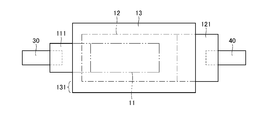
- FIG. 2 is a partial cross-sectional view showing, in an enlarged manner, a cross section viewed from a direction along the line II-II in FIG. 1 in a laminated nonaqueous electrolyte secondary battery before sealing.
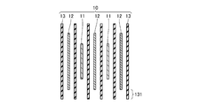
- FIG. 3 is a schematic partial cross-sectional view showing, in an enlarged manner, a cross section of the electrode structure viewed from the direction along the line III-III in FIG. 1 inside the laminated nonaqueous electrolyte secondary battery before sealing.
- FIG. 2 is an exploded perspective view of the laminate type nonaqueous electrolyte secondary battery shown in FIG. 1.
- a laminated nonaqueous electrolyte secondary battery 100 which is an example of a nonaqueous electrolyte secondary battery includes an electrode structure 10 and an illustrated structure.
- a non-aqueous electrolyte solution, a rectangular shape, and an outer packaging body 20 composed of an electrode structure 10 and two upper and lower flexible packaging members 20a and 20b that contain and seal the non-aqueous electrolyte solution, and an electrode
- the structure is composed of a positive electrode terminal 30 and a negative electrode terminal 40 that are electrically connected to the structure 10 by ultrasonic welding and led out from the outer peripheral edge of the outer package 20 in opposite directions.
- the outer peripheral edge of the outer package 20 is sealed by thermal welding (heat sealing) at four sealing locations 21a, 21a, 21b, and 21c.
- Either one of the sealing locations 21b or 21c is a first sealing location that does not include a location from which the positive electrode terminal 30 and the negative electrode terminal 40 are led out, and the other is a third sealing location.
- the sealing locations 21a and 21a are second sealing locations including a location where the positive electrode terminal 30 and the negative electrode terminal 40 are led out.
- Each of the positive electrode terminal 30 and the negative electrode terminal 40 is positioned at the center in the width direction of the electrode structure 10, but may be positioned at one end in the width direction.
- one outer packet member 20b constituting the outer packet body 20 has a cup-shaped convex part, but both outer packet members 20a and 20b are cup-shaped convex parts. May have a part.
- the electrode structure 10 includes a plurality of strip-shaped positive electrode members 11, a plurality of strip-shaped negative electrode members 12, and a plurality of strip-shaped separators 13.
- the positive electrode members 11 and the negative electrode members 12 are alternately stacked with the separators 13 interposed therebetween.
- the positive electrode member 11 includes a positive electrode current collector 111, and the plurality of positive electrode members 11 are electrically connected to the positive electrode terminal 30 by ultrasonic welding via end portions 111a in which the plurality of positive electrode current collectors 111 are integrated.
- the negative electrode member 12 includes a negative electrode current collector 121.
- the plurality of negative electrode members 12 are electrically connected to the negative electrode terminal 40 by ultrasonic welding through an end portion where the plurality of negative electrode current collectors 121 are integrated. It is connected.
- one separator 13 is interposed between the positive electrode member 11 and the negative electrode member 12 as a configuration of the electrode structure 10.
- a separator may be interposed.
- the material of the plurality of separators may be the same or different.
- a polyolefin resin such as polypropylene or polyethylene, or a combination thereof, a polyolefin resin added with a ceramic such as silica or alumina, polyethylene terephthalate, cellulose, nonwoven fabric, or the like is used.
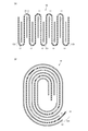
- the positive electrode member 11 may be disposed in a bag-shaped separator, and a separator may be interposed between the positive electrode member 12 and the long separator 13 may be replaced by 90 as shown in FIG. Nine folds may be interposed. 6B, a long separator 13 may be interposed between the long positive electrode member 11 and the negative electrode member 12 and wound.
- the outer packaging members 20 a and 20 b constituting the outer packaging body 20 are positioned on the inner surface side facing the electrode structure 10, and are positioned on the inner surface layer made of synthetic resin and the outer surface of the laminated nonaqueous electrolyte secondary battery 100.
- the inner surface layer is made of polypropylene which is a heat-sealable thermoplastic resin and has a thickness of 30 to 120 ⁇ m.
- the metal layer is made of an aluminum foil or an aluminum alloy foil and has a thickness of 30 to 50 ⁇ m.
- the outer surface layer is made of nylon (registered trademark) and has a thickness of 20 to 40 ⁇ m.
- the outer packaging members 20a and 20b configured in this way are easily deformable materials and have flexibility.
- the laminate film should just have an inner surface layer and the metal layer arrange
- the outer package 20 is heated at the four sides of the sealing locations 21a, 21a, 21b, and 21c by overlapping the outer peripheral edges of the two outer packaging members 20a and 20b made of a laminate film. It is formed by welding.
- each of the positive electrode terminal 30 and the negative electrode terminal 40 is a portion where the end portions of the positive electrode current collector 111 and the negative electrode current collector 121 are integrated.
- each of the positive electrode terminal 30 and the negative electrode terminal 40 may be connected by ultrasonic welding on the upper surface of the portion where the ends of the current collector are integrated, or It may be arranged so that the end of the current collector is inserted into the integrated portion and connected by ultrasonic welding.
- the positive electrode terminal 30 and the negative electrode terminal 40 are led out from the outer peripheral edge portion of the outer package 20 in opposite directions, but the positive electrode terminal 30 and the negative electrode terminal 40 are the outer peripheral edge portion of the outer packaging member. May be derived in the same direction.
- the positive terminal 30 is positioned at one end in the width direction of the electrode structure 10
- the negative terminal 40 is positioned at the other end opposite to the one end in the width direction of the electrode structure 10.
- the laminate type non-aqueous electrolyte secondary battery 100 of the present invention configured as described above is manufactured by housing and enclosing the electrode structure 10 in the outer package 20 in the following steps. .
- the positive electrode terminal 30 and the negative electrode terminal 40 are previously connected to the electrode structure 10 by ultrasonic welding.
- the outer packaging members 20a and 20b constituting the outer packaging body 20 are overlapped and heat-sealed at a sealing location 21b as a first sealing location (first sealing step).
- the electrode structure 10 is disposed so as to be sandwiched between the overlapped outer packaging members 20a and 20b (electrode structure accommodation step).
- the overlapped outer packaging members 20a and 20b are sealed as a second sealing location by heat welding at the sealing location 21a (second sealing step).
- the sealing part 21c (third sealing part) is sealed by thermal welding after injecting the electrolytic solution with the sealing part 21c facing upward (electrolyte injection process / third sealing). Process).
- the sealing part does not include the part from which the positive electrode terminal 30 and the negative electrode terminal 40 are led by overlapping the outer packaging members 20a and 20b.
- the electrode structure 10 is disposed so as to be sandwiched between the overwrapped outer packaging members 20a and 20b.
- the overlapped outer packaging members 20a and 20b are sealed at a sealing location 21a including a location where the positive electrode terminal 30 and the negative electrode terminal 40 are led out.
- the separator 13 which comprises the electrode structure 10 is sealed with the outer packaging members 20a and 20b in the sealing location 21b.
- the portion 131 (FIGS. 3, 4, and 6) of the separator 13 can be prevented from being sealed together with the outer packaging members 20a and 20b at the sealing location 21b.
- the separator 13 constituting the electrode structure 10 is sealed together with the outer packaging members 20a and 20b at the sealing portion 21b, and thus the reliability of the battery due to the decrease in the sealing strength or the sealing property. It is possible to prevent a decrease, an internal short circuit due to a breakage of the separator, and the like.
- the outer dimensions of the outer packaging members 20a and 20b are 160 mm ⁇ 160 mm, and the thickness of the laminated nonaqueous electrolyte secondary battery 100 is about 5 mm.
- the electrode structure 10 shown in FIGS. 2 and 3 is configured such that 20 positive electrode members 11 and 21 negative electrode members 12 are alternately stacked with separators 13 interposed therebetween.
- the positive electrode member 11 has a positive electrode mixture layer containing a positive electrode active material, except for an end portion on the side connected to the positive electrode terminal 30. It is configured by being formed on both surfaces of the body 111.
- the negative electrode member 12 is configured by forming a negative electrode mixture layer containing a negative electrode active material on both surfaces of the negative electrode current collector 121 except for an end portion on the side connected to the negative electrode terminal 40.
- the positive electrode member 11 includes a positive electrode current collector 111 made of an aluminum foil or a copper foil, and a positive electrode mixture slurry formed by kneading a positive electrode active material, a binder, and, if necessary, a conductive agent in an organic solvent. It is produced by coating uniformly on both surfaces of the substrate and drying to form a positive electrode mixture layer on both surfaces of the positive electrode current collector 111.
- the positive electrode active materials include lithium cobaltate composite oxide, lithium manganate composite oxide, lithium nickelate composite oxide, lithium-nickel-manganese-cobalt composite oxide, A lithium-manganese-nickel composite oxide, a lithium-manganese-cobalt composite oxide, a lithium-nickel-cobalt composite oxide, or the like can be used. Further, the positive electrode active material may be a mixture of the above materials.
- LiM x O 2 (in the chemical formula, M represents one or more transition metals, x represents a charge / discharge state of the battery, and is usually 0.05 or more as a positive electrode active material of a non-aqueous electrolyte secondary battery. Or a lithium composite oxide mainly composed of 1.10 or less).
- the transition metal M constituting this lithium composite oxide Co, Ni, Mn and the like are preferable.
- the positive electrode active material may be a lithium-containing phosphate compound having an olivine type structure such as lithium iron phosphate represented by LiFePO 4 . If it has an olivine type structure, in the lithium iron phosphate represented by LiFePO 4 , a part of Fe is replaced with Al, Ti, V, Cr, Mn, Co, Ni, Zr, Nb, etc. Also good. A part of P may be replaced with B, Si, or the like.
- binder contained in the positive electrode mixture a known binder that is usually used in the positive electrode mixture of a non-aqueous electrolyte secondary battery can be used.
- Known additives such as a conductive agent and an oxide can be added to the material.
- conductive agent contained in the positive electrode mixture carbon materials such as furnace black, acetylene black, carbon fiber, and carbon nanotube are used.
- a binder for binding the positive electrode active material and the conductive agent polyvinylidene fluoride (PVDF), polyamideimide (PAI), polyacrylonitrile (PAN), polyethylene (PE), polypropylene (PP), polytetrafluoro Ethylene (PTFE) or fluorine-based latex is used.
- the negative electrode member 12 is formed by uniformly applying a negative electrode slurry obtained by kneading a negative electrode active material, a binder, and, if necessary, a conductive agent in an organic solvent on both surfaces of a negative electrode current collector made of copper foil. It is produced by applying and drying to form a negative electrode mixture layer on both sides of the negative electrode current collector.
- a carbon material such as a non-graphitizable carbon material, a graphitizable carbon material (soft carbon), or a graphite-based carbon material can be used as the negative electrode active material.
- carbon materials such as pyrolytic carbons, cokes, graphites, glassy carbon fibers, organic polymer compound fired bodies, carbon fibers, carbon nanotubes, and activated carbon can be used.
- the cokes include pitch coke, needle coke, and petroleum coke.
- said organic polymer compound fired body means what carbonized by baking a phenol resin, furan resin, etc. at a suitable temperature.
- materials that can be doped or dedoped with lithium include polymers such as polyacetylene and polypyrrole, Sn oxides such as SnO 2 , Sn alloys such as Sn 5 Cu 6 , and SiMg 2.
- An oxide such as an alloy or Li 4 Ti 5 O 12 (lithium titanate) can also be used.
- binder contained in the negative electrode mixture a known binder that is usually used in a negative electrode mixture of a non-aqueous electrolyte secondary battery can be used.
- Known additives such as a conductive agent and an oxide can be added to the material.
- binder for binding the negative electrode active material polyvinylidene fluoride, polyacrylonitrile, polyamideimide, polyacrylonitrile, polyethylene, polypropylene or polytetrafluoroethylene is used, or a latex binder such as styrene butadiene rubber and the like.
- a mixture of thickeners such as carboxymethylcellulose is used.
- the nonaqueous electrolytic solution is prepared by dissolving the supporting electrolyte in a nonaqueous solvent.
- a nonaqueous electrolyte for example, a solution obtained by dissolving LiPF 6 in a non-aqueous solvent at a concentration of 1.0 mol / L is used.
- supporting electrolytes other than LiPF 6 include lithium salts such as LiBF 4 , LiAsF 6 , LiClO 4 , LiCF 3 SO 3 , LiN (SO 2 CF 3 ) 2 , LiC (SO 2 CF 3 ) 3 , LiAlCl 4 , and LiSiF 6. Can be mentioned.
- LiPF 6 and LiBF 4 are particularly preferably used as the supporting electrolyte from the viewpoint of oxidation stability.
- a supporting electrolyte is preferably used by being dissolved in a nonaqueous solvent at a concentration of 0.1 mol / L to 3.0 mol / L, and at a concentration of 0.5 mol / L to 2.0 mol / L. More preferably, it is used after being dissolved.
- the non-aqueous solvent include cyclic carbonates such as ethylene carbonate (EC) and propylene carbonate (PC), dimethyl carbonate (DMC), ethyl methyl carbonate (EMC), and diethyl carbonate (DEC), which are low viscosity solvents. And a lower chain carbonate of the above are used.
- the present invention is applied to the laminated nonaqueous electrolyte secondary battery 100 as an example of an electricity storage device.
- an electricity storage device using an outer packaging member to accommodate at least an electrode structure If so, the present invention can be applied.
- the present invention can be applied to an electric double layer capacitor in addition to a non-aqueous electrolyte secondary battery.
- the outer packaging member is not limited to a flexible member made of a laminate film having a three-layer structure.
- an electricity storage device for example, an electricity storage device that houses various electricity storage elements such as an electric double layer capacitor in addition to a non-aqueous electrolyte secondary battery as an electricity storage element.
- SYMBOLS 10 Electrode structure, 11: Positive electrode member, 12: Negative electrode member, 13: Separator, 20: Outer package, 20a, 20b: Outer package member, 21a, 21b, 21c: Sealing location, 30: Positive electrode terminal, 40: Negative electrode Terminal: 100: Laminated non-aqueous electrolyte secondary battery, 111: Positive electrode current collector, 121: Negative electrode current collector.
Landscapes
- Chemical & Material Sciences (AREA)
- Chemical Kinetics & Catalysis (AREA)
- Electrochemistry (AREA)
- General Chemical & Material Sciences (AREA)
- Engineering & Computer Science (AREA)
- Power Engineering (AREA)
- Manufacturing & Machinery (AREA)
- Microelectronics & Electronic Packaging (AREA)
- Secondary Cells (AREA)
- Sealing Battery Cases Or Jackets (AREA)
Abstract
セパレータが外包部材とともに封着されることを防止することが可能な蓄電デバイスの製造方法を提供する。ラミネート型非水電解液二次電池(100)の製造方法において、外包体(20)を構成する外包部材(20a、20b)を重ね合わせて、封着箇所(21b)にて熱溶着することにより、封着する。その後、重ね合わせられた外包部材(20a、20b)で電極構造体(10)を挟むようにして配置する。そして、重ね合わせられた外包部材(20a、20b)を封着箇所(21a)にて熱溶着することにより、封着する。
Description
本発明は、一般的には蓄電デバイスの製造方法に関し、特定的には、非水電解液二次電池、電気二重層キャパシタ等の蓄電要素を、複数の外包部材を重ね合わせて封着して収容する蓄電デバイスの製造方法に関するものである。
従来から、たとえば、非水電解液二次電池等の蓄電デバイスに関しては、多様な用途の拡大に伴って、軽量化、薄型化、形状の自由度等の要求が高まっている。
そこで、軽量化、薄型化に優れた非水電解液二次電池として、外包部材として可撓性のラミネートフィルム(積層シートともいう)を用いて電極構造体を収容した非水電解液二次電池が用いられている。ラミネートフィルムは、電極構造体に面する内面側に位置付けられ、合成樹脂からなる内面層と、非水電解液二次電池の外表面に位置付けられ、合成樹脂からなる外面層と、内面層と外面層との間に配置される中間層とから構成される。内面層は、たとえば、ポリエチレン、ポリプロピレン等の耐電解液性と熱溶着性に優れた熱可塑性樹脂からなる。中間層は、たとえば、アルミニウム箔等の可撓性と強度に優れた金属層からなる。外面層は、たとえば、ナイロン、ポリアミド等の電気絶縁性に優れた絶縁樹脂からなる。電極構造体(電池要素ともいう)は、セパレータを介して正極部材と負極部材とを巻回させて、または、交互に積層させて、構成される。
たとえば、国際公開第2005/086258号(以下、特許文献1という)には、上記の非水電解液二次電池として、フィルム外装電池の構成が開示されている。このフィルム外装電池は、電極構造体を電解液とともに収納する外包体を備えている。電極構造体は、複数の正極板と複数の負極板とをセパレータを介して交互に積層して構成されている。外包体は、電極構造体をその厚み方向両側から挟んで包囲する2枚のラミネートフィルムからなる。重ね合わせられた2枚のラミネートフィルムの外周縁部(矩形状の平面形状では四辺)を熱溶着により封着することによって、電極構造体を外包体の内部に封入している。なお、このような構成は、5mm以上の厚みを有する電極構造体を収容する場合に望ましい形態である。
特許文献1に記載のフィルム外装電池では、電極構造体を2枚のラミネートフィルムで挟んで配置した後、電解液を入れるための開口部以外の三辺を熱溶着により封着している。そして、電解液を注入した後に開口部の一辺を熱溶着により封着している。
しかしながら、電極構造体を2枚のラミネートフィルムで挟んで配置する際に、電極構造体の配置がずれる場合がある。この場合、正極端子(正極タブともいう)または負極端子(負極タブともいう)が配置されて導出される箇所を含む辺以外の一辺を封着する際に、電極構造体を構成するセパレータがラミネートフィルムとともに封着されることがある。
セパレータがラミネートフィルムとともに封着されると、ラミネートフィルムの溶着が不十分になる。このため、封着強度または封着性の低下による電池の信頼性の低下、セパレータの破損による内部短絡、等の問題を引き起こす恐れがある。
そこで、本発明の目的は、セパレータが外包部材とともに封着されることを防止することが可能な蓄電デバイスの製造方法を提供することである。
本発明の製造方法が対象とする蓄電デバイスは、セパレータを介在して正極部材と負極部材とを交互に配置することにより形成された電極構造体と、電極構造体を収容して外周縁部で封着された外包体とを備える。正極部材が正極集電体を含み、負極部材が負極集電体を含む。さらに、蓄電デバイスは、正極集電体の端部に電気的に接続されるとともに外包体の外周縁部から導出された正極端子と、負極集電体の端部に電気的に接続されるとともに外包体の外周縁部から導出された負極端子とを備える。外包体の外周縁部が、正極端子と負極端子が導出される箇所を含まない第1の封着箇所と、正極端子と負極端子が導出される箇所を含む第2の封着箇所とを有する。
上記のように構成された蓄電デバイスの製造方法は、以下の工程を備える。
(A)外包体を構成する第1と第2の外包部材を重ね合わせて第1の封着箇所で封着する第1の封着工程
(B)第1の封着工程の後、重ね合わせられた第1と第2の外包部材で電極構造体を挟むようにして配置する電極構造体収容工程
(C)電極構造体収容工程の後、重ね合わせられた第1と第2の外包部材を第2の封着箇所で封着する第2の封着工程
本発明の蓄電デバイスの製造方法では、外包体を構成する第1と第2の外包部材を重ね合わせて、正極端子と負極端子が導出される箇所を含まない第1の封着箇所で予め封着した後、重ね合わせられた第1と第2の外包部材で電極構造体を挟むようにして配置する。その後、重ね合わせられた第1と第2の外包部材を、正極端子と負極端子が導出される箇所を含む第2の封着箇所で封着する。これにより、電極構造体を構成するセパレータが第1の封着箇所で第1と第2の外包部材とともに封着されることを防止することができる。
本発明の製造方法が対象とする蓄電デバイスにおいて、電極構造体は、セパレータを介在して複数の正極部材と複数の負極部材とを交互に積層することにより形成されていることが好ましい。
また、本発明の製造方法は、さらに以下の工程を備える。
(D)第2の封着工程の後、未封着の第3の封着箇所を上にした状態で電解液を注入する電解液注入工程
(E)電解液注入工程の後、第3の封着箇所で封着する第3の封着工程
本発明によれば、電極構造体を構成するセパレータが、正極端子と負極端子が導出される箇所を含まない封着箇所で外包部材とともに封着されることを防止することができるので、封着強度または封着性の低下による電池の信頼性の低下、セパレータの破損による内部短絡、等を防止することができる。
以下、本発明の一つの実施の形態を図面に基づいて説明する。
図1~図5に示すように、蓄電デバイスの一つの実施の形態として、非水電解液二次電池の一例であるラミネート型非水電解液二次電池100は、電極構造体10と、図示しない非水電解液と、矩形状を有し、電極構造体10と非水電解液を収容して封止する上下二枚の可撓性の外包部材20a、20bからなる外包体20と、電極構造体10に超音波溶着により電気的に接続されるとともに外包体20の外周縁部から互いに対向する反対方向に導出された正極端子30および負極端子40とから構成される。外包体20の外周縁部は、四方の封着箇所21a、21a、21b、21cにて熱溶着(ヒートシール)によって封着されている。封着箇所21b、または21cのいずれか一方は、正極端子30と負極端子40が導出される箇所を含まない第1の封着箇所であり、他方は第3の封着箇所である。また、封着箇所21a、21aは、正極端子30と負極端子40が導出される箇所を含む第2の封着箇所である。正極端子30および負極端子40のそれぞれは、電極構造体10の幅方向の中央に位置づけられているが、幅方向の一方端部に位置づけられてもよい。また、この実施の形態では、図5に示すように外包体20を構成する一方の外包部材20bがカップ形状の凸部を有しているが、両方の外包部材20a、20bがカップ形状の凸部を有していてもよい。
図2と図3に示すように、電極構造体10は、複数の短冊状の正極部材11と、複数の短冊状の負極部材12と、複数の短冊状のセパレータ13とを含む。正極部材11と負極部材12がセパレータ13を間に介在して交互に積層されている。正極部材11は正極集電体111を含み、複数の正極部材11が、複数の正極集電体111を集積した端部111aを介して正極端子30に超音波溶着により電気的に接続されている。負極部材12は負極集電体121を含み、複数の負極部材12も正極部材と同様に、複数の負極集電体121を集積した端部を介して負極端子40に超音波溶着により電気的に接続されている。なお、上記のラミネート型非水電解液二次電池100の例では、電極構造体10の構成として正極部材11と負極部材12との間に一枚のセパレータ13を介在させているが、複数枚のセパレータを介在させてもよい。複数枚のセパレータの材質は同種でも異種でもよい。セパレータの材質としては、ポリプロピレン、ポリエチレン等のポリオレフィン系樹脂の単独またはその組み合わせ、ポリオレフィン系樹脂にシリカ、アルミナ等のセラミックを添加したもの、ポリエチレンテレフタレート、セルロース、不織布等が用いられる。また、たとえば、正極部材11を袋状のセパレータ内に配置して負極部材12との間にセパレータを介在させてもよく、図6(A)に示すように長尺状のセパレータ13を九十九折りにして介在させてもよい。なお、図6(B)に示すように長尺状の正極部材11と負極部材12との間に、長尺状のセパレータ13を介在させ、巻回させてもよい。
外包体20を構成する外包部材20a、20bは、電極構造体10に面する内面側に位置づけられ、合成樹脂からなる内面層と、ラミネート型非水電解液二次電池100の外表面に位置づけられ、合成樹脂からなる外面層と、内面層と外面層との間に配置される金属層とから構成される単一のフィルム、すなわち、三層構造のラミネートフィルムで形成されている(図2では三層構造は省略している)。内面層は、一例として、ヒートシール可能な熱可塑性樹脂であるポリプロピレンからなり、厚みが30~120μmである。金属層は、一例として、アルミニウム箔またはアルミニウム合金箔からなり、厚みが30~50μmである。外面層は、一例として、ナイロン(登録商標)からなり、厚みが20~40μmである。このように構成された外包部材20a、20bは、容易に変形しやすい材料であり、可撓性を有する。なお、ラミネートフィルムは、少なくとも内面層とその外側に配置される金属層とを有するものであればよく、必要に応じて外面層を設ければよい。また、必要に応じて層間にウレタン樹脂等の接着層、他の合成樹脂層等を設けてもよい。図1と図5に示すように、外包体20は、ラミネートフィルムからなる2枚の外包部材20a、20bの外周縁部を重ね合わせて四辺の封着箇所21a、21a、21b、21cにて熱溶着することによって形成される。
上記の実施形態では、図2と図4に示されるように、正極端子30と負極端子40のそれぞれは、正極集電体111と負極集電体121のそれぞれの端部が集積された箇所の下面にて超音波溶着により接続されるが、正極端子30と負極端子40のそれぞれは、集電体の端部が集積された箇所の上面にて超音波溶着により接続されてもよく、あるいは、集電体の端部が集積された箇所の内部に挿入されるように配置して超音波溶着により接続されてもよい。
また、上記の実施形態では、正極端子30および負極端子40は外包体20の外周縁部から互いに対向する反対方向に導出されているが、正極端子30および負極端子40が外包部材の外周縁部から同じ方向に導出されていてもよい。この場合、正極端子30が電極構造体10の幅方向の一方端部に位置づけられ、負極端子40が電極構造体10の幅方向の一方端部と反対側の他方端部に位置づけられる。
以上のように構成された本発明のラミネート型非水電解液二次電池100は、次のような工程にて、電極構造体10を外包体20内に収容して封入することにより製造される。なお、下記の製造工程を行う前には、正極端子30および負極端子40が超音波溶着により電極構造体10に予め接続されている。
まず、外包体20を構成する外包部材20a、20bを重ね合わせて、第1の封着箇所として封着箇所21bにて熱溶着することにより、封着する(第1の封着工程)。
その後、重ね合わせられた外包部材20a、20bで電極構造体10を挟むようにして配置する(電極構造体収容工程)。
そして、重ね合わせられた外包部材20a、20bを第2の封着箇所として封着箇所21aにて熱溶着することにより、封着する(第2の封着工程)。
なお、封着箇所21c(第3の封着箇所)は、封着箇所21cを上にした状態で電解液を注入した後に熱溶着により封着される(電解液注入工程・第3の封着工程)。
以上のように本発明のラミネート型非水電解液二次電池100の製造方法では、外包部材20a、20bを重ね合わせて、正極端子30と負極端子40が導出される箇所を含まない封着箇所21bで予め封着した後、重ね合わせられた外包部材20a、20bで電極構造体10を挟むようにして配置する。その後、重ね合わせられた外包部材20a、20bを、正極端子30と負極端子40が導出される箇所を含む封着箇所21aで封着する。これにより、電極構造体10を構成するセパレータ13が封着箇所21bで外包部材20a、20bとともに封着されることを防止することができる。具体的には、セパレータ13の部分131(図3、図4、図6)が封着箇所21bで外包部材20a、20bとともに封着されることを防止することができる。
したがって、電極構造体10を構成するセパレータ13が封着箇所21bで外包部材20a、20bとともに封着されることに起因して、封着強度または封着性が低下することによる電池の信頼性の低下、セパレータが破損することによる内部短絡、等を防止することができる。
一例として、図5に示される形態にて外包部材20a、20bの平面外形寸法は160mm×160mm、ラミネート型非水電解液二次電池100の厚みは約5mmである。図2と図3に示される形態の電極構造体10において、20枚の正極部材11と21枚の負極部材12がセパレータ13を間に介在して交互に積層されるように構成される。
なお、本発明のラミネート型非水電解液二次電池100において、正極部材11は、正極端子30に接続される側の端部を除いて、正極活物質を含む正極合材層が正極集電体111の両面上に形成されることによって構成される。負極部材12は、負極端子40に接続される側の端部を除いて、負極活物質を含む負極合材層が負極集電体121の両面上に形成されることによって構成される。
たとえば、正極部材11は、正極活物質と結着剤と必要に応じて導電剤とを有機溶媒中で混錬してなる正極合材スラリーを、アルミニウム箔または銅箔からなる正極集電体111の両面上に均一に塗布し、乾燥して、正極合材層を正極集電体111の両面上に形成することにより作製される。
非水電解液二次電池を構成する場合、正極活物質としては、コバルト酸リチウム複合酸化物、マンガン酸リチウム複合酸化物、ニッケル酸リチウム複合酸化物、リチウム‐ニッケル‐マンガン‐コバルト複合酸化物、リチウム‐マンガン‐ニッケル複合酸化物、リチウム‐マンガン‐コバルト複合酸化物、リチウム‐ニッケル‐コバルト複合酸化物等を用いることができる。さらに、正極活物質は、上記の材料を混合したものでもよい。具体的には、非水電解液二次電池の正極活物質としてLiMxO2(化学式中、Mは一種以上の遷移金属を表し、xは電池の充放電状態によって異なり、通常0.05以上、1.10以下である)を主体とするリチウム複合酸化物等を使用することができる。このリチウム複合酸化物を構成する遷移金属Mとしては、Co、Ni、Mn等が好ましい。このようなリチウム複合酸化物の具体例としてはLiCoO2、LiNiO2、LiNiyCo1-yO2(化学式中、0<y<1である)、Li1+a(NixMnyCoz)O2-b(化学式中、-0.1<a<0.2、x+y+z=1、-0.1<b<0.1)、LiMn2O4等を挙げることができる。これらのリチウム複合酸化物は、高電圧を発生でき、エネルギー密度が優れた正極活物質となる。正極部材11を作製するために、これらの正極活物質の複数種をあわせて使用してもよい。正極活物質は、LiFePO4で表わされるリン酸鉄リチウム等のオリビン型構造を有するリチウム含有リン酸化合物でもよい。オリビン型構造を有しているのであれば、LiFePO4で表わされるリン酸鉄リチウムにおいて、Feの一部をAl、Ti、V、Cr、Mn、Co、Ni、Zr、Nb等で置換してもよい。また、Pの一部をB、Si等で置換してもよい。
また、上記の正極合材に含有される結着剤としては、通常、非水電解液二次電池の正極合材に用いられている公知の結着剤を用いることができ、上記の正極合材には、導電剤、酸化物等、公知の添加剤を添加することができる。上記の正極合材に含有される導電剤としては、ファーネスブラック、アセチレンブラック、炭素繊維、カーボンナノチューブ等の炭素材料が用いられる。正極活物質と導電剤を結着させるための結着剤としては、ポリフッ化ビニリデン(PVDF)、ポリアミドイミド(PAI)、ポリアクリロニトリル(PAN)、ポリエチレン(PE)、ポリプロピレン(PP)、ポリテトラフルオロエチレン(PTFE)またはフッ素系ラテックスが用いられる。
たとえば、負極部材12は、負極活物質と結着剤と必要に応じて導電剤とを有機溶媒中で混錬してなる負極スラリーを、銅箔からなる負極集電体の両面上に均一に塗布し、乾燥して、負極合材層を負極集電体の両面上に形成することにより作製される。
非水電解液二次電池を構成する場合、負極活物質としては、難黒鉛化炭素材料、易黒鉛化炭素材料(ソフトカーボン)、グラファイト系炭素材料等の炭素材料を使用することができる。具体的には、熱分解炭素類、コークス類、黒鉛類、ガラス状炭素繊維、有機高分子化合物焼成体、炭素繊維、カーボンナノチューブ、活性炭等の炭素材料を使用することができる。上記のコークス類には、ピッチコークス、ニードルコークス、石油コークス等がある。また、上記の有機高分子化合物焼成体とは、フェノール樹脂、フラン樹脂等を適当な温度で焼成して炭素化したものをいう。上述した炭素材料のほか、リチウムをドープ、脱ドープできる材料としては、ポリアセチレン、ポリピロール等の高分子、SnO2等のSn酸化物系、Sn5Cu6等のSn合金系、SiMg2等のSi合金系、Li4Ti5O12(チタン酸リチウム)等の酸化物を使用することもできる。
また、上記の負極合材に含有される結着剤としては、通常、非水電解液二次電池の負極合材に用いられている公知の結着剤を用いることができ、上記の負極合材には、導電剤、酸化物等、公知の添加剤を添加することができる。負極活物質を結着させるための結着剤としては、ポリフッ化ビニリデン、ポリアクリロニトリル、ポリアミドイミド、ポリアクリロニトリル、ポリエチレン、ポリプロピレンまたはポリテトラフルオロエチレンが用いられ、あるいは、スチレンブタジエンラバー等のラテックスバインダーとカルボキシメチルセルロース等の増粘剤の混合物が用いられる。
非水電解液は、支持電解質を非水溶媒に溶解して調製される。非水電解液としては、たとえば、非水溶媒中にLiPF6を1.0mol/Lの濃度で溶解したものが使用される。LiPF6以外の支持電解質としては、LiBF4、LiAsF6、LiClO4、LiCF3SO3、LiN(SO2CF3)2、LiC(SO2CF3)3、LiAlCl4、LiSiF6等のリチウム塩を挙げることができる。これらの中でも、支持電解質として特にLiPF6、LiBF4を用いることが酸化安定性の点から望ましい。このような支持電解質は、非水溶媒中に、0.1mol/L~3.0mol/Lの濃度で溶解されて用いられることが好ましく、0.5mol/L~2.0mol/Lの濃度で溶解されて用いられることがさらに好ましい。上記の非水溶媒としては、エチレンカーボネート(EC)、プロピレンカーボネート(PC)等の環状炭酸エステルに、低粘性溶媒であるジメチルカーボネート(DMC)、エチルメチルカーボネート(EMC)、ジエチルカーボネート(DEC)等の低級鎖状炭酸エステルを加えたものが用いられる。
上記の実施の形態では、本発明を蓄電デバイスの一例としてラミネート型非水電解液二次電池100に適用した例について説明したが、少なくとも電極構造体を収容するために外包部材を用いた蓄電デバイスであれば、本発明を適用することができ、たとえば、非水電解液二次電池の他に、電気二重層キャパシタ等に本発明を適用することができる。なお、外包部材は、三層構造のラミネートフィルム等からなる可撓性を有するものに限定されない。
今回開示された実施の形態はすべての点で例示であって制限的なものではないと考慮されるべきである。本発明の範囲は以上の実施の形態ではなく、請求の範囲によって示され、請求の範囲と均等の意味および範囲内でのすべての修正または変形を含むものであることが意図される。
本発明によれば、封着強度または封着性の低下による電池の信頼性の低下、セパレータの破損による内部短絡、等を防止することができるので、可撓性を有する外包部材が使用可能な蓄電デバイス、たとえば、蓄電要素として非水電解液二次電池の他に、電気二重層キャパシタ等の種々の蓄電要素を収容する蓄電デバイスの信頼性の向上に寄与するものである。
10:電極構造体、11:正極部材、12:負極部材、13:セパレータ、20:外包体、20a,20b:外包部材、21a,21b,21c:封着箇所、30:正極端子、40:負極端子、100:ラミネート型非水電解液二次電池、111:正極集電体、121:負極集電体。
Claims (4)
- セパレータを介在して正極部材と負極部材とを交互に配置することにより形成された電極構造体と、前記電極構造体を収容して外周縁部で封着された外包体とを備え、前記正極部材が正極集電体を含み、前記負極部材が負極集電体を含み、さらに、前記正極集電体の端部に電気的に接続されるとともに前記外包体の外周縁部から導出された正極端子と、前記負極集電体の端部に電気的に接続されるとともに前記外包体の外周縁部から導出された負極端子とを備え、前記外包体の外周縁部が、前記正極端子と前記負極端子が導出される箇所を含まない第1の封着箇所と、前記正極端子と前記負極端子が導出される箇所を含む第2の封着箇所とを有する蓄電デバイスの製造方法であって、
前記外包体を構成する第1と第2の外包部材を重ね合わせて前記第1の封着箇所で封着する第1の封着工程と、
前記第1の封着工程の後、重ね合わせられた前記第1と第2の外包部材で前記電極構造体を挟むようにして配置する電極構造体収容工程と、
前記電極構造体収容工程の後、重ね合わせられた前記第1と第2の外包部材を前記第2の封着箇所で封着する第2の封着工程とを備えた、蓄電デバイスの製造方法。 - 前記電極構造体は、セパレータを介在して複数の正極部材と複数の負極部材とを交互に積層することにより形成されている、請求項1に記載の蓄電デバイスの製造方法。
- 前記正極端子および前記負極端子が、前記外包体の外周縁部から互いに反対方向に延びている、請求項1または請求項2のいずれか1項に記載の蓄電デバイスの製造方法。
- 前記第2の封着工程の後、未封着の第3の封着箇所を上にした状態で電解液を注入する電解液注入工程と、
前記電解液注入工程の後、前記第3の封着箇所で封着する第3の封着工程とを備えた、請求項1から請求項3までのいずれか1項に記載の蓄電デバイスの製造方法。
Applications Claiming Priority (2)
| Application Number | Priority Date | Filing Date | Title |
|---|---|---|---|
| JP2011-117173 | 2011-05-25 | ||
| JP2011117173 | 2011-05-25 |
Publications (1)
| Publication Number | Publication Date |
|---|---|
| WO2012160965A1 true WO2012160965A1 (ja) | 2012-11-29 |
Family
ID=47217046
Family Applications (1)
| Application Number | Title | Priority Date | Filing Date |
|---|---|---|---|
| PCT/JP2012/061816 Ceased WO2012160965A1 (ja) | 2011-05-25 | 2012-05-09 | 蓄電デバイスの製造方法 |
Country Status (1)
| Country | Link |
|---|---|
| WO (1) | WO2012160965A1 (ja) |
Cited By (1)
| Publication number | Priority date | Publication date | Assignee | Title |
|---|---|---|---|---|
| US11830672B2 (en) | 2016-11-23 | 2023-11-28 | KYOCERA AVX Components Corporation | Ultracapacitor for use in a solder reflow process |
Citations (5)
| Publication number | Priority date | Publication date | Assignee | Title |
|---|---|---|---|---|
| JP2009238508A (ja) * | 2008-03-26 | 2009-10-15 | Fdk Corp | 電気化学的デバイス、および電気化学的デバイスの製造方法 |
| JP2010192230A (ja) * | 2009-02-18 | 2010-09-02 | Murata Mfg Co Ltd | 非水電解液二次電池 |
| JP2010199281A (ja) * | 2009-02-25 | 2010-09-09 | Fuji Heavy Ind Ltd | 蓄電デバイスおよびその製造方法 |
| JP2010244930A (ja) * | 2009-04-08 | 2010-10-28 | Hitachi Maxell Ltd | ラミネート形電池の製造方法 |
| JP2010244725A (ja) * | 2009-04-01 | 2010-10-28 | Sony Corp | 非水電解質電池 |
-
2012
- 2012-05-09 WO PCT/JP2012/061816 patent/WO2012160965A1/ja not_active Ceased
Patent Citations (5)
| Publication number | Priority date | Publication date | Assignee | Title |
|---|---|---|---|---|
| JP2009238508A (ja) * | 2008-03-26 | 2009-10-15 | Fdk Corp | 電気化学的デバイス、および電気化学的デバイスの製造方法 |
| JP2010192230A (ja) * | 2009-02-18 | 2010-09-02 | Murata Mfg Co Ltd | 非水電解液二次電池 |
| JP2010199281A (ja) * | 2009-02-25 | 2010-09-09 | Fuji Heavy Ind Ltd | 蓄電デバイスおよびその製造方法 |
| JP2010244725A (ja) * | 2009-04-01 | 2010-10-28 | Sony Corp | 非水電解質電池 |
| JP2010244930A (ja) * | 2009-04-08 | 2010-10-28 | Hitachi Maxell Ltd | ラミネート形電池の製造方法 |
Cited By (1)
| Publication number | Priority date | Publication date | Assignee | Title |
|---|---|---|---|---|
| US11830672B2 (en) | 2016-11-23 | 2023-11-28 | KYOCERA AVX Components Corporation | Ultracapacitor for use in a solder reflow process |
Similar Documents
| Publication | Publication Date | Title |
|---|---|---|
| JP4659861B2 (ja) | 扁平型二次電池およびその製造方法 | |
| US20110244304A1 (en) | Stack type battery | |
| JP5591569B2 (ja) | 角形電池及びその製造方法ならびにこれを用いてなる組電池 | |
| JP5830953B2 (ja) | 二次電池、バッテリユニットおよびバッテリモジュール | |
| JP6504158B2 (ja) | 積層型電池及びその製造方法 | |
| US9614194B2 (en) | Battery | |
| CN103311574B (zh) | 非水电解质二次电池 | |
| CN112018447A (zh) | 锂离子二次电池元件、电池和制造该电池元件的方法 | |
| KR20120053463A (ko) | 비-수성 전해질 전지 | |
| JP2013206699A (ja) | 電気化学デバイス | |
| WO2013002058A1 (ja) | 蓄電デバイス | |
| WO2017039143A1 (ko) | 전극 조립체, 이를 포함하는 이차 전지 및 그 제조방법 | |
| US20150111095A1 (en) | Lithium-Ion Battery | |
| JP2005310588A (ja) | バイポーラ電池、バイポーラ電池の製造方法、組電池およびこれらを搭載した車両 | |
| CN106663839A (zh) | 非水电解质电池和电池组 | |
| JP2009187675A (ja) | 積層型二次電池およびその製造方法 | |
| JP4725578B2 (ja) | 電気化学デバイス、及び電気化学デバイスの製造方法 | |
| JP2010161249A (ja) | リチウムイオンキャパシタ | |
| US20160293921A1 (en) | Battery | |
| JP2012151036A (ja) | ラミネート形電池 | |
| WO2011070918A1 (ja) | 蓄電デバイスとその製造方法 | |
| US20150079448A1 (en) | Nonaqueous electrolyte battery | |
| KR20170014293A (ko) | 이차 전지 모듈 및 그 제조 방법과 이를 구비하는 전지 팩 | |
| KR101785573B1 (ko) | 이차 전지 모듈 및 그 제조 방법과 이를 구비하는 전지 팩 | |
| JP6149867B2 (ja) | 蓄電デバイスの製造方法 |
Legal Events
| Date | Code | Title | Description |
|---|---|---|---|
| 121 | Ep: the epo has been informed by wipo that ep was designated in this application |
Ref document number: 12790348 Country of ref document: EP Kind code of ref document: A1 |
|
| NENP | Non-entry into the national phase |
Ref country code: DE |
|
| 122 | Ep: pct application non-entry in european phase |
Ref document number: 12790348 Country of ref document: EP Kind code of ref document: A1 |
|
| NENP | Non-entry into the national phase |
Ref country code: JP |