WO2012160948A1 - 通報システムおよび通報装置 - Google Patents
通報システムおよび通報装置 Download PDFInfo
- Publication number
- WO2012160948A1 WO2012160948A1 PCT/JP2012/061361 JP2012061361W WO2012160948A1 WO 2012160948 A1 WO2012160948 A1 WO 2012160948A1 JP 2012061361 W JP2012061361 W JP 2012061361W WO 2012160948 A1 WO2012160948 A1 WO 2012160948A1
- Authority
- WO
- WIPO (PCT)
- Prior art keywords
- battery
- notification
- voltage
- equal
- unit
- Prior art date
- Legal status (The legal status is an assumption and is not a legal conclusion. Google has not performed a legal analysis and makes no representation as to the accuracy of the status listed.)
- Ceased
Links
Images


Classifications
-
- H—ELECTRICITY
- H04—ELECTRIC COMMUNICATION TECHNIQUE
- H04M—TELEPHONIC COMMUNICATION
- H04M1/00—Substation equipment, e.g. for use by subscribers
- H04M1/72—Mobile telephones; Cordless telephones, i.e. devices for establishing wireless links to base stations without route selection
- H04M1/724—User interfaces specially adapted for cordless or mobile telephones
- H04M1/72403—User interfaces specially adapted for cordless or mobile telephones with means for local support of applications that increase the functionality
- H04M1/72418—User interfaces specially adapted for cordless or mobile telephones with means for local support of applications that increase the functionality for supporting emergency services
Definitions
- the present invention relates to a notification system, and in particular, a notification system and a notification including a transmission terminal that transmits a notification command and a notification device that performs predetermined notification processing according to the notification command received from the transmission terminal It relates to the device.
- an emergency notification command is sent to a notification device that is wirelessly connected to the transmission terminal.
- An emergency notification system has been developed in which a notification device that transmits an emergency notification command and sends an emergency notification to an emergency notification reception center or the like via a telephone line or the like.
- an emergency notification command is sent to the notification device when the voltage of the battery falls below a predetermined threshold. It becomes impossible to send.
- the battery voltage is monitored, and when it is detected that the voltage has become equal to or lower than a predetermined threshold necessary for driving the transmission terminal, the notification device is informed that the battery has run out. There is something that has been.
- the internal impedance of the battery built in the transmitter terminal changes greatly depending on the environmental temperature used, and when the emergency notification command is transmitted to the reporting device, the voltage fluctuates greatly. It is difficult to detect in a stable state.
- Patent Document 1 Japanese Patent Laid-Open No. 2001-228221
- the charge of a lithium battery for driving a small wireless transmitter as a transmitting terminal is changed to a lithium battery. It is configured to detect the decrease in capacity of the lithium battery in a stable state with high accuracy by measuring the voltage of the lithium battery based on this electric charge.
- a battery capacity reduction detection circuit and a small wireless transmitter are disclosed.
- An object of the present invention is to eliminate the above-mentioned problems.
- the state is appropriately determined.
- the purpose is to provide a notification system and a notification device for reporting to the Internet.
- the first invention of the present application is a reporting system comprising: a transmitting terminal that transmits a notification command; and a reporting device that performs a reporting process according to the notification command received from the transmitting terminal.
- Voltage determination means for determining whether or not the voltage of the battery driving the transmitting terminal is equal to or lower than a predetermined threshold, and the number of times that the voltage is determined to be lower than or equal to the threshold in a predetermined time range
- a number-of-times determining means for determining whether or not the number of times is equal to or greater than a predetermined number of times, and a process of notifying that the battery is dead when the number of times that the voltage is equal to or less than the threshold is determined to be equal to or greater than the predetermined number of times
- a notification processing means for determining whether or not the voltage of the battery driving the transmitting terminal is equal to or lower than a predetermined threshold, and the number of times that the voltage is determined to be lower than or equal to the threshold in a predetermined time range
- the voltage determination means determines whether or not the voltage of the battery is equal to or lower than the threshold at a first time interval that is the time interval, When it is determined that the voltage is equal to or lower than the threshold value, it is determined whether the voltage of the battery is equal to or lower than the threshold value based on a second time interval that is the time interval shorter than the first time interval.
- the notification processing means performs a process of notifying that the battery is dead within a predetermined time zone. It is characterized by.
- the fourth invention of the present application is the notification system according to the third invention, wherein the time zone is a time zone excluding a specific time zone.
- the transmission terminal has a voltage of a battery that drives the transmission terminal equal to or lower than a predetermined threshold value.
- a transmission terminal comprising voltage determination means for determining whether or not there is a predetermined time interval, wherein the notification device has a predetermined number of times that the voltage is determined to be less than or equal to the threshold value within a predetermined time range.
- a number of times determination means for determining whether or not the number of times when the voltage is equal to or less than the threshold is determined to be greater than or equal to the predetermined number of times
- a notification processing means for performing a process of reporting that the battery is dead, It is characterized by providing.
- a sixth invention of the present application is a notification device that performs notification processing according to the notification command received from the transmission terminal that transmits the voltage of the battery that drives the transmission terminal and transmits the notification command
- the notification device includes the transmission Voltage determination means for determining whether or not the battery voltage received from the terminal is equal to or less than a predetermined threshold, and a predetermined number of times that the voltage is determined to be equal to or less than the threshold in a predetermined time range Number of times determination means for determining whether or not the number of times is not less than, and a notification process for performing a process of notifying that the battery is out of battery when the number of times that the voltage is equal to or less than the threshold is determined to be equal to or more than the predetermined number And means.
- the voltage determining means determines whether or not the voltage of the battery driving the transmitting terminal is equal to or lower than a predetermined threshold at a predetermined time interval, and the frequency determining means determines the voltage within a predetermined time range. Determining whether or not the number of times that the voltage is determined to be equal to or less than the threshold is greater than or equal to a predetermined number of times, and when the notification processing means determines that the number of times that the voltage is equal to or less than the threshold is equal to or greater than the predetermined number of times, A process for reporting that the battery is dead is performed.
- the voltage of the battery driving the transmitting terminal can be accurately determined in a stable state based on the averaged voltage. Can do. And when it determines with a voltage being below a predetermined threshold value, it can report appropriately that it is out of a battery.
- the battery voltage is determined at the first time interval, and when it is determined that the battery is dead, the battery is charged at a second time interval shorter than the first time interval.
- the reporting system when it is determined that the battery has run out, an inappropriate time is obtained by performing a process of reporting the battery running out within a predetermined time zone. It is possible to avoid the situation where the notification process is performed in the belt.
- the reporting time zone in the reporting system according to the third invention, by setting the reporting time zone to a specific time zone other than the time zone such as nighttime, for example, the notification is performed at night, so that it is sleeping The situation where the user's sleep is disturbed can be avoided.
- reporting apparatus which comprises the alerting
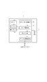
- FIG. 2 is a configuration block diagram of a receiving adapter constituting the notification system shown in FIG. 1.
- FIG. 2 is a configuration block diagram of a telephone unit constituting the notification system shown in FIG. 1.
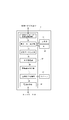
- It is a process flowchart of the pendant part which comprises the notification system shown in FIG.
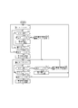
- It is a process flowchart of the telephone part which comprises the notification system shown in FIG.
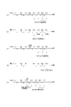
- It is a timing chart of a battery exhaustion notification process in the telephone part which comprises the notification system shown in FIG.
- FIG. 1 is a block diagram showing the configuration of a notification system 10 according to an embodiment of the present invention.
- the notification system 10 includes a pendant unit 11 that is a transmission terminal carried by a user, a reception adapter 12 that receives a command transmitted from the pendant unit 11 by wireless communication, and a USB connection to the reception adapter 12. Based on a command transmitted via the receiving adapter 12, a predetermined notification process is performed, and a telephone unit 13 which is a notification device having a function as an IP-TV telephone is provided.
- the telephone unit 13 is configured to be connectable to a transmission destination 15 set corresponding to the pendant unit 11 via a network 14 such as an optical communication network. Note that a plurality of pendant units 11 that can be individually identified by the ID information can be connected to the receiving adapter 12.
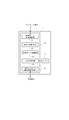
- FIG. 2 is a configuration block diagram of the pendant unit 11 constituting the notification system 10.
- the pendant unit 11 includes a control unit 17 that controls the operation of the pendant unit 11 with electric power supplied from a battery 16 such as a built-in lithium battery.
- the control unit 17 includes a button press monitoring unit 18, a timer monitoring unit 19, a voltage monitoring unit 20, and a data transmission control unit 21.
- the button press monitoring unit 18 monitors, for example, whether or not the button 22 is pressed by the user in an emergency.
- the timer monitoring unit 19 controls the start (time measurement start), reset, and switching of the first timer 23 and the second timer 24 having different set time over times T1 and T2, and monitors the time measurement.
- the voltage monitoring unit 20 is connected to the battery 16 when the battery 16 is inserted into the pendant unit 11, when the user presses the button 22, or when the time measured by the first timer 23 or the second timer 24 has expired. Monitor the voltage.
- the data transmission control unit 21 performs control to generate an emergency notification command together with ID information for specifying the pendant unit 11 and wirelessly transmit it to the reception adapter 12.
- the data transmission control unit 21 functions as a voltage determination unit that determines whether or not the voltage of the battery 16 monitored by the voltage monitoring unit 20 is equal to or lower than a predetermined threshold, and the voltage of the battery 16 is equal to or lower than the predetermined threshold. When it is determined, the battery control unit generates a battery deadline notification command together with the ID information and performs wireless transmission to the receiving adapter 12.
- FIG. 3 is a block diagram showing the configuration of the receiving adapter 12 constituting the notification system 10.
- the reception adapter 12 includes a control unit 25.
- the control unit 25 includes a wireless data reception control unit 26, an operation state monitoring unit 27, a setting data storage unit 28, an LED control unit 29, and a USB message transmission / reception control unit 30.
- the wireless data reception control unit 26 performs control to receive ID information, an emergency notification command, and a battery exhaustion notification command that are wirelessly transmitted from the pendant unit 11.
- the operation state monitoring unit 27 monitors the registration state of the reception adapter 12 with respect to the telephone unit 13, the registration state of the pendant unit 11 with respect to the reception adapter 12, and the transmission state of data from the pendant unit 11.
- the setting data storage unit 28 stores the ID information of the receiving adapter 12, the ID information of the pendant unit 11 connected to the receiving adapter 12, and the number of registered units.
- the LED control unit 29 performs control to display each state monitored by the operation state monitoring unit 27 according to lighting, blinking, lighting, and blinking time intervals of the LED 31.
- the USB message transmission / reception control unit 30 performs control to transmit the ID information, the emergency notification command, and the battery exhaustion notification command of the pendant unit 11 wirelessly transmitted from the pendant unit 11 to the telephone unit 13 via the USB cable.
- FIG. 4 is a configuration block diagram of the telephone unit 13 constituting the notification system 10.
- the telephone unit 13 includes a control unit 32.
- the control unit 32 includes a USB message transmission / reception control unit 33, a display / key control unit 34, a setting data storage unit 35, a log storage unit 36, a notification operation determination unit 37, a notification operation control unit 38 and a telephone control unit 39.
- the USB message transmission / reception control unit 33 transmits / receives a signal to / from the reception adapter 12, and transmits the ID information of the pendant unit 11, an emergency notification command, and a battery exhaustion notification command transmitted from the pendant unit 11 through the reception adapter 12. Control to receive.
- the display / key control unit 34 controls the display unit 40 and the key 41 to display various functions as an IP-TV telephone and to control key input, and also to an emergency call start command and / or a battery deadline report start command. Based on the notification image display control.
- the setting data storage unit 35 stores the ID information of the receiving adapter 12, the ID information of the pendant unit 11 connected to the receiving adapter 12, and the registered number of the same as the setting data storage unit 28 of the receiving adapter 12. In addition, the setting data storage unit 35 stores the telephone number of the transmission destination 15 that transmits an emergency call from the user carrying the pendant unit 11 in association with the ID information of the pendant unit 11.
- the log storage unit 36 includes an emergency notification command that is an operation request command transmitted from the pendant unit 11 via the reception adapter 12, a battery exhaustion notification command, and a log for the year, month, and date when the command is received. 11 together with ID information.
- the notification operation determination unit 37 and the notification operation control unit 38 operate as follows and function as notification processing means.
- the notification operation determination unit 37 analyzes the operation request command and determines whether the notification operation can be executed. For example, when an emergency notification command is transmitted from the pendant unit 11, the notification operation determination unit 37 issues an emergency notification start command to make an emergency notification. Further, the notification operation determination unit 37 checks the log of the battery exhaustion notification command transmitted from the pendant unit 11 and stored in the log storage unit 36, and the number (number of times) of battery exhaustion commands in a predetermined time range is predetermined.
- predetermined number it is determined whether or not the number (predetermined number) or more, and when it is equal to or greater than the predetermined number (predetermined number), it functions as a number-of-times determination unit that issues a battery deadline notification start command in order to report the battery dead.
- the notification operation control unit 38 controls the display / key control unit 34 according to the notification start command issued by the notification operation determination unit 37, and executes an emergency notification and / or a battery exhaustion notification control operation. Furthermore, the notification operation control unit 38 can perform notification according to the emergency notification and / or the battery exhaustion notification via the speaker 42.
- the telephone control unit 39 selects the destination 15 set corresponding to the ID information of the pendant unit 11 that has transmitted the emergency notification command from the setting data storage unit 35 in accordance with the emergency notification control operation by the notification operation control unit 38. Then, emergency information is sent to the destination 15 by telephone.
- FIG. 5 is a process flowchart in the pendant unit 11
- FIG. 6 is a process flowchart in the telephone unit 13.
- the timer monitoring unit 19 of the pendant unit 11 starts the first timer 23 and starts measuring time (step S101).
- step S102 the button pressing monitoring unit 18 detects that the emergency notification button 22 has been pressed by the user carrying the pendant unit 11 (step S102: YES)
- step S102 the button pressing monitoring unit 18 notifies the voltage monitoring unit 20 that the button 22 has been pressed.
- the voltage monitoring unit 20 supplies voltage data of the battery 16 at that time to the data transmission control unit 21.
- the data transmission control unit 21 determines whether or not the voltage of the battery 16 that is the data supplied from the voltage monitoring unit 20 is equal to or lower than a predetermined threshold that prevents the pendant unit 11 from operating normally. If it is determined that the value is higher than the threshold (step S103: YES), an emergency notification command based on pressing of the button 22 is generated and transmitted to the receiving adapter 12 together with the ID information of the pendant unit 11 (step S104).
- step S103 NO
- step S103 the data transmission control unit 21 determines that the voltage of the battery 16 is equal to or lower than the threshold
- step S105 the data transmission control unit 21 generates an emergency notification command and a battery exhaustion notification command, and displays these notification commands as a pendant.
- step S105 After being transmitted to the receiving adapter 12 together with the ID information of the unit 11 (step S105), the process proceeds to the process of step S109 described later (starting time measurement by the second timer 24).
- step S103 when the voltage of the battery 16 is higher than the predetermined threshold (step S103: YES), or when the button 22 is not pressed (step S102: NO), the processing from step S102 is repeated (step S106: NO). ).
- step S106 When the button 22 is not pressed and the time measured by the first timer 23 reaches the time over time T1 (for example, 168 hours) (step S106: YES), the data transmission control unit 21 monitors the voltage monitoring unit 20. The voltage of the battery 16 is compared with a predetermined threshold value. When it is determined that the voltage of the battery 16 is higher than the threshold (step S107: YES), the timer monitoring unit 19 resets the first timer 23 and then restarts the time measurement by the first timer 23 (step S101). ), The process from step S102 is repeated.
- step S106 When the time-over time T1 of the first timer 23 has elapsed (step S106: YES), the data transmission control unit 21 determines whether or not the voltage of the battery 16 is equal to or lower than a predetermined threshold, and is determined to be equal to or lower than the threshold. In such a case (step S107: NO), the data transmission control unit 21 generates a battery exhaustion notification command and transmits it to the reception adapter 12 together with the ID information of the pendant unit 11 (step S108).
- step S108 or S105 when the battery deadline notification command is transmitted to the receiving adapter 12, the timer monitoring unit 19 starts the second timer 24 and starts measuring time (step S109).
- the time over time T2 of the second timer 24 is set to a time shorter than the time over time T1 of the first timer 23 (for example, 12 hours).
- step S110: YES the voltage is monitored.
- the monitoring unit 20 is notified that the button 22 has been pressed, and the voltage monitoring unit 20 supplies the data of the voltage of the battery 16 at that time to the data transmission control unit 21.
- the data transmission control unit 21 determines whether or not the voltage of the battery 16 that is the data supplied from the voltage monitoring unit 20 is equal to or lower than a predetermined threshold that prevents the pendant unit 11 from operating normally. If it is determined that the value is higher than the threshold (step S111: YES), an emergency notification command based on pressing of the button 22 is generated and transmitted to the reception adapter 12 together with the ID information of the pendant unit 11 (step S112). Next, the timer monitoring unit 19 starts the first timer 23 again (step S101), and repeats the processing from step S102.
- step S111: NO when the data transmission control unit 21 determines that the voltage of the battery 16 is equal to or lower than the threshold (step S111: NO), the data transmission control unit 21 generates an emergency notification command and a battery exhaustion notification command, and sends these notification commands to the pendant unit 11.
- the ID information is transmitted to the receiving adapter 12 (step S113).
- step S109 the timer monitoring unit 19 restarts the time measurement by the second timer 24 (step S109), and repeats the processing from step S110. If the button 22 is not pressed after the second timer 24 is started (step S110: NO), the processing from step S110 is repeated (step S114: NO).
- step S114 When the button 22 is not pressed and the time measured by the second timer 24 reaches the time over time T2 (for example, 12 hours) (step S114: YES), the data transmission control unit 21 monitors the voltage monitoring unit 20. The voltage of the battery 16 is compared with a predetermined threshold value. When it is determined that the voltage of the battery 16 is higher than the threshold (step S115: YES), the timer monitoring unit 19 switches from the second timer 24 to the first timer 23, and starts the time measurement by the first timer 23 again. (Step S101), the processing from Step S102 is repeated.
- step S115 the case where it is determined in step S115 that the voltage of the battery 16 is higher than the threshold is, for example, the voltage of the battery 16 temporarily in a low-temperature environment or other fluctuation factors during the previous voltage check. Is lowered, and then the voltage returns to a normal value due to an increase in environmental temperature or the like.
- step S115 when it is determined that the voltage of the battery 16 is equal to or lower than the predetermined threshold (step S115: NO), the data transmission control unit 21 generates a battery deadline notification command and receives it together with the ID information of the pendant unit 11. It transmits to the adapter 12 (step S116). Next, the timer monitoring unit 19 restarts the second timer 24 (step S109) and repeats the processing from step S110.
- the notification operation determination unit 37 of the telephone unit 13 analyzes the operation request command transmitted from the reception adapter 12 and, based on pressing of the button 22 by the user carrying the pendant unit 11, the pendant unit via the reception adapter 12. If it is determined that an emergency notification command has been received from 11 (step S201: YES), the emergency notification command and the logs for the year, month, and date that received the emergency notification command are stored in the log storage unit 36 together with the ID information of the pendant unit 11 (step S201). S202). Next, the notification operation determination unit 37 issues an emergency notification start command according to the received emergency notification command (step S203), and supplies it to the notification operation control unit 38.
- the notification operation control unit 38 Upon receiving the emergency call start command, the notification operation control unit 38 executes an emergency call control operation. For example, the notification operation control unit 38 controls the display / key control unit 34 to notify that an emergency notification is transmitted from the user of the pendant unit 11 using the display unit 40 and drives the speaker 42. Then, an alarm for an emergency notification is notified. Furthermore, the notification operation control unit 38 selects the telephone number of the destination 15 stored in the setting data storage unit 35 according to the ID information of the pendant unit 11 that has transmitted the emergency notification command, and via the network 14, An emergency call is transmitted to the selected destination 15. The emergency notification may be sent to the family of the user who owns the pendant unit 11, or may be an emergency call reception server of a medical center provided in the area if the environment is in place.
- the notification operation determination unit 37 of the telephone unit 13 analyzes the operation request command transmitted from the reception adapter 12 and outputs a battery exhaustion notification command indicating that the voltage of the battery 16 of the pendant unit 11 is equal to or lower than the threshold value. If it is determined that it has been received (step S204: YES), the battery storage notification command and the logs for the year, month, and date that received it are stored in the log storage unit 36 together with the ID information of the pendant unit 11 (step S205). When the battery exhaustion notification command has not been received (step S204: NO), the processing from step S201 is repeated.
- the notification operation determination unit 37 determines whether or not the emergency notification command is received together with the battery running notification command. That is, the pendant unit 11 checks the voltage of the battery 16 when the user presses the button 22 (steps S103 and S111). Therefore, when both the emergency notification command and the battery exhaustion notification command are received (step S206: YES), the notification operation determination unit 37 issues a battery exhaustion notification start command according to the received battery exhaustion notification command (step S209). The notification operation control unit 38 is supplied.
- the notification operation control unit 38 that has received the battery low notification start command together with the emergency notification command executes a battery low notification control operation.
- the notification operation control unit 38 controls the display / key control unit 34 and uses the display unit 40 to notify that the battery 16 of the pendant unit 11 may run out of battery, and also drives the speaker 42. Then, the alarm of battery exhaustion is notified.
- the notification operation control unit 38 selects the telephone number of the call destination 15 stored in the setting data storage unit 35 according to the ID information of the pendant unit 11 that has transmitted the battery deadline notification command, and via the network 14. Then, a battery exhaustion notice is transmitted to the selected destination 15.
- step S201 when only the battery exhaustion notification command is received from the pendant unit 11 via the reception adapter 12 (step S201: NO, S206: NO), the notification operation determination unit 37 is a time zone in which the current time is a night time (for example, , 22:00 to 7:00).
- step S207 When it is determined that it is a night time zone (step S207: YES), the process from step S201 is repeated without performing the battery exhaustion notification process.
- step S207: NO the notification operation determination unit 37 logs the year, month, day, and time when the battery deadline notification command stored in the log storage unit 36 is received. Based on the above, it is determined whether or not the telephone unit 13 has received a battery exhaustion notification command N times or more (for example, four times or more) from the same pendant unit 11 within a predetermined time (for example, within 49 hours). If it is determined that the number of battery-out notification commands within the predetermined time is less than N (step S208: NO), the process from step S201 is repeated without performing the battery-out notification process.
- N for example, four times or more
- the notification operation determination unit 37 issues a battery deadline notification start command according to the received battery deadline notification command.
- the notification operation control unit 38 is supplied.
- the notification operation control unit 38 which has received the battery start notification start command controls the display / key control unit 34 and uses the display unit 40 to notify that the battery 16 of the pendant unit 11 may run out of battery,
- the speaker 42 is driven to notify a battery exhaustion alarm.
- the notification operation control unit 38 selects the telephone number of the call destination 15 stored in the setting data storage unit 35 according to the ID information of the pendant unit 11 that has transmitted the battery deadline notification command, and via the network 14. Then, a battery exhaustion notice is transmitted to the selected destination 15.
- FIG. 7 is a timing chart in the case where it is determined that the battery 16 has naturally deteriorated and the battery has run out, and a battery running notification is started.
- the pendant unit 11 checks the voltage of the battery 16 when the time measured by the first timer 23 has exceeded the time over time T1 (for example, 168 hours), and determines that the voltage is equal to or lower than a predetermined threshold value. Is sent to the telephone unit 13.
- This battery exhaustion notification command NG1 is stored in the log storage unit 36 of the telephone unit 13 together with the logs for the year, month, and date when the command is received.
- the pendant unit 11 checks the voltage of the battery 16 when a time-over time T2 (for example, 12 hours) shorter than the time-over time T1 elapses by the time measured by the second timer 24.
- a time-over time T2 for example, 12 hours
- T1 time-over time
- the voltage continues to be equal to or lower than the predetermined threshold value, and therefore the pendant unit 11 transmits a second battery exhaustion notification command NG2 to the telephone unit 13.
- This battery exhaustion notification command NG2 is stored in the log storage unit 36 together with a log for the year, month, and date when the command is received.
- the pendant unit 11 checks the voltage of the battery 16 every time the time-over time T2 elapses, determines that the voltage is not more than a predetermined threshold value, and notifies the third time, the fourth time,.
- Commands NG3, NG4,... Are transmitted to the telephone unit 13.
- These battery exhaustion notification commands NG3, NG4,... are sequentially stored in the log storage unit 36 together with the logs for the year, month, and date when the command is received.
- the telephone unit 13 determines whether or not the battery exhaustion notification commands NG1, NG2,... Received within a predetermined time are N times or more based on the logs for the year, month, day and time when the command is received, and N times When the above is reached (for example, four times or more), a battery exhaustion notification start command is issued, and then a battery exhaustion notification is made every time the battery exhaustion notification commands NG5, NG6,.
- (B) of FIG. 7 is a timing chart in the case of avoiding the time zone of the battery exhaustion notification at night, for example, 22:00 to 7:00.
- the telephone unit 13 receives the Nth battery exhaustion notification command within a predetermined time and reports the battery exhaustion, for example, the time when the fifth battery exhaustion notification command NG5 is received is 22:00 to When it is a night time zone in the range of 7:00, the battery exhaustion notification command NG5 is stored in the log storage unit 36, but the battery exhaustion notification based on the battery exhaustion notification command NG5 is not performed. Thereby, it is possible to avoid a situation in which a sleeping user or the like is bothered by reporting that the battery has run out at night. Note that the telephone unit 13 notifies the battery exhaustion when the sixth battery exhaustion notification command NG6 is received after the night time period has elapsed.
- (C) of FIG. 7 is a timing chart when reception of the battery exhaustion notification command from the pendant unit 11 fails.
- the telephone unit 13 allows a predetermined time for receiving the battery deadline notification command to be allowed to fail to receive one battery deadline notification command, and considers an error in signal transmission timing from the pendant unit 11,
- the battery exhaustion can be reported based on the received battery exhaustion notification commands NG4, NG5,... After the Nth (for example, the fourth) reception.
- (D) of FIG. 7 is a timing chart when the voltage of the battery 16 of the pendant unit 11 is restored in a low temperature environment and then recovered due to a temperature rise.
- the voltage of the battery 16 may temporarily decrease, and the pendant unit 11 may transmit a battery deadline notification command to the telephone unit 13.
- the pendant unit 11 determines that the battery has run out due to a voltage drop due to low temperature at the time when the time-over time T1 (for example, 168 hours) of the first timer 23 has elapsed, the pendant unit 11 transmits the battery running notification command NG1 to the telephone unit 13. .
- the pendant unit 11 switches the first timer 23 to the second timer 24 and checks the voltage of the battery 16 again after a time over time T2 (for example, 12 hours) by the second timer 24 has elapsed.
- the pendant unit 11 does not transmit a battery exhaustion notification command (OK).
- the voltage of the battery 16 is checked again. If it is determined that the battery has run out at this time, the pendant unit 11 transmits the battery running notification command NG1 to the telephone unit 13 and then switches to the second timer 24 to check the voltage in the same manner as described above.
- battery deadline notification commands NG2, NG3,... are sequentially transmitted to the telephone unit 13.
- the telephone unit 13 determines whether or not the battery exhaustion notification command NG1 (second battery exhaustion notification command NG1), NG2,. When it becomes N times or more (for example, 4 times or more), a battery low notification start command is issued, and then a battery low notification is received every time the battery low notification commands NG5, NG6,. I do.
- the telephone unit 13 subsequently increases the environmental temperature of the pendant unit 11 in the daytime and the voltage is increased.
- the first battery exhaustion notification command NG1 is excluded from the number of battery exhaustion notification commands received within (T2 ⁇ N + 1) hours. It is possible to avoid a situation where the battery is detected and an inappropriate battery exhaustion notification is made.
- (E) of FIG. 7 is a timing chart including the case where the button 22 of the pendant part 11 is pressed by the user.
- the pendant unit 11 checks the voltage of the battery 16, and when it is determined that the battery is exhausted, the pendant unit 11 transmits the battery exhaustion notification command to the telephone unit 13 together with the emergency notification command.
- the telephone unit 13 makes an emergency call and a battery deadline notification based on the battery deadline notification command transmitted together with the emergency notification command.
- the battery exhaustion notification since it is necessary to notify the emergency call even if the current time is midnight, it is not inconvenient to report the battery exhaustion at the same time.
- the number of times of the battery exhaustion notification command from the time when the time over time T1 switches to T2 is counted, and the battery exhaustion notification is notified when the number of times reaches N or more. The user can be notified without delay that the battery 16 of the pendant unit 11 is out of battery.
- this invention is not limited to the Example mentioned above, It can change in the range which does not deviate from the summary of this invention.
- the voltage check of the battery 16 in the pendant unit 11 is not performed when the user presses the button 22 or the first timer 23 and the second timer 24 are over, but the battery 16 is inserted into the pendant unit 11. It is preferable to do it on occasion.
- the voltage check of the battery 16 has been described as being performed by the pendant unit 11, but the voltage data monitored by the voltage monitoring unit 20 of the pendant unit 11 is transmitted to the telephone unit 13, and the voltage is checked by the telephone unit 13. You may make it check by comparing with a predetermined threshold value.
- the number N of battery-notification notification commands for reporting a battery exhaustion is as follows. May be set arbitrarily.
Landscapes
- Engineering & Computer Science (AREA)
- Business, Economics & Management (AREA)
- Emergency Management (AREA)
- Human Computer Interaction (AREA)
- Computer Networks & Wireless Communication (AREA)
- Signal Processing (AREA)
- Alarm Systems (AREA)
- Telephonic Communication Services (AREA)
- Telephone Function (AREA)
Abstract
送信端末を駆動する電池の電圧を安定した状態で精度良く判定し、電池切れと判定された場合、その状態を適切に通報する通報システムを提供する。 通報システムは、通知コマンドを送信する送信端末11と、前記送信端末11から受信した前記通知コマンドに従った通報処理を行う通報装置13とを備える通報システム10において、前記送信端末11を駆動する電池の電圧が所定の閾値以下であるか否かを、所定の時間間隔で判定する電圧判定手段と、所定の時間範囲で、前記電圧が前記閾値以下と判定された回数が所定回数以上であるか否かを判定する回数判定手段と、前記電圧が前記閾値以下となる回数が前記所定回数以上と判定されたとき、前記電池が電池切れであることを通報する処理を行う通報処理手段と、を備える。
Description
本発明は、通報システムに関するものであり、特に、通知コマンドを送信する送信端末と、前記送信端末から受信した前記通知コマンドに従った所定の通報処理を行う通報装置と、を備える通報システムおよび通報装置に関するものである。
例えば、ペンダント型や腕時計型の送信端末を利用者が常時携行し、緊急時等において、利用者が送信端末のボタンを操作することにより、送信端末に無線接続されている通報装置に緊急通知コマンドを送信し、緊急通知コマンドを受信した通報装置が、電話回線等を介して緊急通報受付センタ等に緊急通報するようにした緊急通報システムが開発されている。
ところで、このような緊急通報システムに用いられる送信端末は、内蔵されている電池によって駆動されるように構成されているため、電池の電圧が所定の閾値以下になると、緊急通知コマンドを通報装置に送信することができなくなってしまう。
このような事態を回避ため、電池の電圧を監視し、電圧が送信端末の駆動に必要な所定の閾値以下になったことを検出したとき、通報装置に対して電池切れを報知するように構成されているものがある。
しかしながら、送信端末に内蔵されている電池は、使用する環境温度によって内部インピーダンスが大きく変化し、また、緊急通知コマンドを通報装置に送信する際には、電圧が大きく変動するため、電池の電圧を安定した状態で検出することが困難である。
そこで、このような事態を回避するため、例えば、下記の特許文献1(特開2001-228221号公報)では、送信端末である小型無線送信機を駆動するためのリチウム電池の電荷を、リチウム電池の無負荷時又は微小負荷時においてコンデンサに蓄積し、この電荷に基づいてリチウム電池の電圧を測定することにより、リチウム電池の容量低下を、安定した状態で精度良く検出するように構成した「リチウム電池の容量低下検出回路及び小型無線送信機」を開示している。
しかしながら、上記の特許文献1の場合、リチウム電池の電荷をコンデンサに蓄積するタイミングによっては、安定した電圧を検出できないことがある。例えば、低温環境下では、リチウム電池の電圧が著しく低下してしまう問題があり、また、小型無線送信機が緊急通知コマンドを通報装置に送信しているときにも電圧が変動する。そのため、このような状況下でコンデンサに電荷を蓄積すると、リチウム電池の容量を正しく反映させた電圧を検出することができなくなってしまう。
また、低温環境下で使用する場合、ユーザが外気にさらされる状態にある時に、リチウム電池の電圧が閾値より低下したことを検出しても、ユーザが屋内に戻り環境温度が上昇するとリチウム電池の電圧が正常値に戻ることがあり、このような状態を繰り返した後に真の電池切れの状態になる。従って、最初の電圧低下の検出が電池交換の必要性をユーザに報知した場合、ユーザが屋内に戻り環境温度が上昇するとリチウム電池の電圧が正常値に戻った場合には、ユーザに対してシステムに不具合があるとの誤解を与え、真に電池交換が必要になった時に、ユーザに電池交換をためらわせる結果となりかねないという問題点も存在している。
本発明は、上記の問題点を解消することを課題とするものであり、送信端末を駆動する電池の電圧を安定した状態で精度良く判定し、電池切れと判定された場合、その状態を適切に通報する通報システムおよび通報装置を提供することを目的とするものである。
前記課題を解決するために、本願の第1発明は、通知コマンドを送信する送信端末と、前記送信端末から受信した前記通知コマンドに従った通報処理を行う通報装置とを備える通報システムにおいて、前記送信端末を駆動する電池の電圧が所定の閾値以下であるか否かを、所定の時間間隔で判定する電圧判定手段と、所定の時間範囲で、前記電圧が前記閾値以下と判定された回数が所定回数以上であるか否かを判定する回数判定手段と、前記電圧が前記閾値以下となる回数が前記所定回数以上と判定されたとき、前記電池が電池切れであることを通報する処理を行う通報処理手段と、を備えることを特徴とする。
本願の第2発明は、第1発明に係る通報システムにおいて、前記電圧判定手段は、前記電池の電圧が前記閾値以下であるか否かを、前記時間間隔である第1時間間隔で判定し、前記閾値以下と判定されたとき、前記電池の電圧が前記閾値以下であるか否かを、前記第1時間間隔よりも短い前記時間間隔である第2時間間隔で判定することを特徴とする。
本願の第3発明は、第1発明又は題2発明に係る通報システムにおいて、前記通報処理手段は、所定の時間帯の範囲内で、前記電池が 電池切れであることを通報する処理を行うことを特徴とする。
本願の第4発明は、第3発明に係る通報システムにおいて、前記時間帯は、特定の時間帯を除く時間帯であることを特徴とする。
本願の第5発明は、通知コマンドを送信する送信端末から受信した前記通知コマンドに従った通報処理を行う通報装置において、前記送信端末は、送信端末を駆動する電池の電圧が所定の閾値以下であるか否かを所定の時間間隔で判定する電圧判定手段を備える送信端末であり、前記通報装置は、所定の時間範囲で、前記電圧が前記閾値以下と判定された回数が所定回数以上であるか否かを判定する回数判定手段と、前記電圧が前記閾値以下となる回数が前記所定回数以上と判定されたとき、前記電池が電池切れであることを通報する処理を行う通報処理手段と、を備えることを特徴とする。
本願の第6発明は、送信端末を駆動する電池の電圧を送信するとともに通知コマンドを送信する送信端末から受信した前記通知コマンドに従った通報処理を行う通報装置において、前記通報装置は、前記送信端末から受信した電池の電圧が所定の閾値以下であるか否かを所定の時間間隔で判定する電圧判定手段と、所定の時間範囲で、前記電圧が前記閾値以下と判定された回数が所定回数以上であるか否かを判定する回数判定手段と、前記電圧が前記閾値以下となる回数が前記所定回数以上と判定されたとき、前記電池が電池切れであることを通報する処理を行う通報処理手段と、を備えることを特徴とする。
第1発明においては、電圧判定手段より、前記送信端末を駆動する電池の電圧が所定の閾値以下であるか否かを、所定の時間間隔で判定し、回数判定手段により、所定の時間範囲で、前記電圧が前記閾値以下と判定された回数が所定回数以上であるか否かを判定し、通報処理手段により、前記電圧が前記閾値以下となる回数が前記所定回数以上と判定されたとき、前記電池が電池切れであることを通報する処理を行う。
このように構成することにより、電圧が変動するような不安定な状況であっても、平均化された電圧に基づいて、送信端末を駆動する電池の電圧を安定した状態で精度良く判定することができる。そして、電圧が所定の閾値以下であると判定された場合、電池切れであることを適切に通報することができる。
第2発明においては、第1発明に係る通報システムにおいて、第1時間間隔で電池の電圧を判定し、電池切れと判定された場合、前記第1時間間隔よりも短い第2時間間隔で電池の電圧を判定することにより、電池切れをより確実且つ遅滞なく判定して通報することができる。
第3発明においては、第1発明又は第2発明に係る通報システムにおいて、電池切れと判定されたとき、所定の時間帯の範囲内で電池切れを通報する処理を行うことにより、不適切な時間帯で通報処理が行われる事態を回避することができる。
第4発明においては、第3発明に係る通報システムにおいて、通報する時間帯を夜間等の時間帯を除く特定の時間帯とすることにより、例えば夜間に通報が行われてしまうことで、就寝中の利用者の安眠を妨げるといった事態を回避することができる。
第5発明、第6発明においては、第1発明の通報システムを構成する通報装置を提供することができるようになる。
以下、本発明の具体例を実施例及び図面を用いて詳細に説明する。但し、以下に示す実施形態は、本発明の技術的思想を具体化するための通報システムおよび通報装置を例示するものであって、本発明をこの通報システムおよび通報装置に特定することを意図するものではなく、特許請求の範囲に含まれるその他の実施形態の通報システムおよび通報装置にも等しく適応し得るものである。
図1は、本発明の一実施例である通報システム10の構成ブロック図である。通報システム10は、利用者が携帯する送信端末であるペンダント部11と、ペンダント部11から送信されたコマンドを無線通信により受信する受信アダプタ12と、受信アダプタ12にUSB接続され、ペンダント部11から受信アダプタ12を介して送信されたコマンドに基づき、所定の通報処理を行うとともに、IP-TV電話機としての機能を有する通報装置である電話部13とを備える。電話部13は、光通信網等のネットワーク14を介して、ペンダント部11に対応して設定された発信先15と接続可能に構成される。なお、受信アダプタ12には、ID情報によって個別に識別可能な複数台のペンダント部11が接続可能である。
図2は、通報システム10を構成するペンダント部11の構成ブロック図である。ペンダント部11は、内蔵されたリチウム電池等の電池16から供給される電力により、ペンダント部11の動作制御を行う制御部17を備える。
制御部17は、ボタン押下監視部18、タイマ監視部19、電圧監視部20及びデータ送信制御部21を備える。ボタン押下監視部18は、例えば、緊急時において利用者により押下されるボタン22の押下の有無を監視する。タイマ監視部19は、設定されるタイムオーバ時間T1及びT2が異なる第1タイマ23及び第2タイマ24のスタート(計時開始)、リセット及び切り替えを制御するとともに、その計時時間を監視する。
電圧監視部20は、ペンダント部11に電池16が挿入された時、利用者がボタン22を押下した時、又は、第1タイマ23若しくは第2タイマ24による計時時間がタイムオーバした時の電池16の電圧を監視する。データ送信制御部21は、利用者がボタン22を押下した時、当該ペンダント部11を特定するID情報とともに、緊急通知コマンドを生成して受信アダプタ12に無線送信する制御を行う。
また、データ送信制御部21は、電圧監視部20により監視された電池16の電圧が所定の閾値以下であるか否かを判定する電圧判定手段として機能し、電池16の電圧が所定の閾値以下と判定されたとき、前記ID情報とともに、電池切れ通知コマンドを生成して受信アダプタ12に無線送信する制御を行う。
図3は、通報システム10を構成する受信アダプタ12の構成ブロック図である。受信アダプタ12は、制御部25を備える。制御部25は、無線データ受信制御部26、動作状態監視部27、設定データ記憶部28、LED制御部29及びUSBメッセージ送受信制御部30を備える。無線データ受信制御部26は、ペンダント部11から無線送信されるID情報、緊急通知コマンド及び電池切れ通知コマンドを受信する制御を行う。動作状態監視部27は、受信アダプタ12の電話部13に対する登録状態、ペンダント部11の受信アダプタ12に対する登録状態、ペンダント部11からのデータの送信状態を監視する。
設定データ記憶部28は、受信アダプタ12のID情報、受信アダプタ12に接続されるペンダント部11のID情報及びその登録台数を記憶する。LED制御部29は、動作状態監視部27により監視される各状態を、LED31の点灯、点滅、点灯及び点滅の時間間隔により表示する制御を行う。USBメッセージ送受信制御部30は、ペンダント部11から無線送信されるペンダント部11のID情報、緊急通知コマンド、電池切れ通知コマンドを、USBケーブルを介して電話部13に送信する制御を行う。
図4は、通報システム10を構成する電話部13の構成ブロック図である。電話部13は、制御部32を備える。制御部32は、USBメッセージ送受信制御部33、表示・キー制御部34、設定データ記憶部35、ログ記憶部36、通報動作判定部37、通報動作制御部38及び電話制御部39を備える。
USBメッセージ送受信制御部33は、受信アダプタ12との間で信号の送受信を行うとともに、受信アダプタ12を介してペンダント部11から送信されるペンダント部11のID情報、緊急通知コマンド、電池切れ通知コマンドを受信する制御を行う。表示・キー制御部34は、表示部40及びキー41を制御し、IP-TV電話機としての各種機能の表示やキー入力の制御を行うとともに、緊急通報開始コマンド及び/又は電池切れ通報開始コマンドに基づく通報画像の表示制御を行う。
設定データ記憶部35は、受信アダプタ12の設定データ記憶部28と同様に、受信アダプタ12のID情報、受信アダプタ12に接続されるペンダント部11のID情報及びその登録台数を記憶する。また、設定データ記憶部35は、ペンダント部11のID情報に対応させて、当該ペンダント部11を携帯する利用者からの緊急通報を発信する発信先15の電話番号等を記憶する。ログ記憶部36は、受信アダプタ12を介してペンダント部11から送信された動作要求コマンドである緊急通知コマンド、電池切れ通知コマンド、及び、そのコマンドを受信した年月日時分のログを、ペンダント部11のID情報とともに記憶する。
通報動作判定部37、通報動作制御部38は以下のように動作し、通報処理手段として機能する。通報動作判定部37は、前記動作要求コマンドを解析し、通報動作実行の可否を判定する。例えば、通報動作判定部37は、ペンダント部11から緊急通知コマンドが送信された場合、緊急通報をすべく、緊急通報開始コマンドを発行する。また、通報動作判定部37は、ペンダント部11から送信され、ログ記憶部36に記憶されている電池切れ通知コマンドのログをチェックし、所定の時間範囲における電池切れコマンドの数(回数)が所定数(所定回数)以上であるか否かを判定し、所定数(所定回数)以上である場合に、電池切れ通報をすべく、電池切れ通報開始コマンドを発行する回数判定手段として機能する。
通報動作制御部38は、通報動作判定部37により発行された通報開始コマンドに従い、表示・キー制御部34を制御し、緊急通報及び/又は電池切れ通報の制御動作を実行する。さらに、通報動作制御部38は、スピーカ42を介して、緊急通報及び/又は電池切れ通報に応じた報知を行うことができる。電話制御部39は、通報動作制御部38による緊急通報の制御動作に従い、緊急通知コマンドを送信したペンダント部11のID情報に対応して設定されている発信先15を設定データ記憶部35から選択し、前記発信先15に電話による緊急情報を発信する。
次に、図5及び図6に示す処理フローチャートに従い、本実施例の通報システム10の動作について説明する。ここで、図5は、ペンダント部11における処理フローチャートであり、図6は、電話部13における処理フローチャートである。
先ず、ペンダント部11の動作について説明する。ペンダント部11のタイマ監視部19は、ペンダント部11の電源が投入されると、第1タイマ23をスタートさせて計時を開始する(ステップS101)。ボタン押下監視部18は、ペンダント部11を携帯する利用者により緊急通知のボタン22が押下されたことを検知すると(ステップS102:YES)、電圧監視部20にボタン22が押下されたことを知らせ、電圧監視部20は、その時点における電池16の電圧のデータをデータ送信制御部21に供給する。
データ送信制御部21は、電圧監視部20から供給されたデータである電池16の電圧が、ペンダント部11を正常動作させることのできない所定の閾値以下であるか否かを判定し、電圧が前記閾値よりも高いと判定された場合(ステップS103:YES)、ボタン22の押下に基づく緊急通知コマンドを生成し、ペンダント部11のID情報とともに受信アダプタ12に送信する(ステップS104)。
また、データ送信制御部21は、電池16の電圧が前記閾値以下であると判定した場合には(ステップS103:NO)、緊急通知コマンド及び電池切れ通知コマンドを生成し、これらの通知コマンドをペンダント部11のID情報とともに受信アダプタ12に送信した後(ステップS105)、後述するステップS109の処理(第2タイマ24による計時のスタート)に移行する。
一方、電池16の電圧が所定の閾値よりも高い場合(ステップS103:YES)、又は、ボタン22が押下されない場合には(ステップS102:NO)、ステップS102からの処理を繰り返す(ステップS106:NO)。
ボタン22が押下されることがなく、第1タイマ23による計時がタイムオーバ時間T1(例えば、168時間)に達すると(ステップS106:YES)、データ送信制御部21は、電圧監視部20により監視されている電池16の電圧を所定の閾値と比較する。電池16の電圧が前記閾値よりも高いと判定された場合(ステップS107:YES)、タイマ監視部19は、第1タイマ23をリセットした後、第1タイマ23による計時を再スタートさせ(ステップS101)、ステップS102からの処理を繰り返す。
第1タイマ23のタイムオーバ時間T1が経過し(ステップS106:YES)、データ送信制御部21が、電池16の電圧が所定の閾値以下であるか否かを判定し、閾値以下と判定された場合には(ステップS107:NO)、データ送信制御部21は、電池切れ通知コマンドを生成し、ペンダント部11のID情報とともに受信アダプタ12に送信する(ステップS108)。
ステップS108又はS105において、電池切れ通知コマンドが受信アダプタ12に送信されると、タイマ監視部19は、第2タイマ24をスタートさせて計時を開始する(ステップS109)。なお、第2タイマ24のタイムオーバ時間T2は、第1タイマ23のタイムオーバ時間T1よりも短い時間(例えば、12時間)に設定されている。ボタン押下監視部18は、第2タイマ24が計時している間に、ペンダント部11を携帯する利用者により緊急通知のためボタン22が押下されたことを検知すると(ステップS110:YES)、電圧監視部20にボタン22が押下されたことを知らせ、電圧監視部20は、その時点における電池16の電圧のデータをデータ送信制御部21に供給する。
データ送信制御部21は、電圧監視部20から供給されたデータである電池16の電圧が、ペンダント部11を正常動作させることのできない所定の閾値以下であるか否かを判定し、電圧が前記閾値よりも高いと判定された場合(ステップS111:YES)、ボタン22の押下に基づく緊急通知コマンドを生成し、ペンダント部11のID情報とともに受信アダプタ12に送信する(ステップS112)。次いで、タイマ監視部19は、再び第1タイマ23をスタートさせ(ステップS101)、ステップS102からの処理を繰り返す。
一方、データ送信制御部21は、電池16の電圧が前記閾値以下であると判定した場合(ステップS111:NO)、緊急通知コマンド及び電池切れ通知コマンドを生成し、これらの通知コマンドをペンダント部11のID情報とともに受信アダプタ12に送信する(ステップS113)。次いで、タイマ監視部19は、第2タイマ24をリセットした後、第2タイマ24による計時を再スタートさせ(ステップS109)、ステップS110からの処理を繰り返す。第2タイマ24がスタートした後、ボタン22が押下されない場合には(ステップS110:NO)、ステップS110からの処理を繰り返す(ステップS114:NO)。
ボタン22が押下されることがなく、第2タイマ24による計時がタイムオーバ時間T2(例えば、12時間)に達すると(ステップS114:YES)、データ送信制御部21は、電圧監視部20により監視されている電池16の電圧を所定の閾値と比較する。電池16の電圧が前記閾値よりも高いと判定された場合(ステップS115:YES)、タイマ監視部19は、第2タイマ24から第1タイマ23に切り替え、再び第1タイマ23による計時をスタートさせ(ステップS101)、ステップS102からの処理を繰り返す。なお、ステップS115において、電池16の電圧が前記閾値よりも高いと判定される場合とは、例えば、前回の電圧チェックの際に、低温環境下又はその他の変動要因で一時的に電池16の電圧が低下し、その後、環境温度の上昇等により電圧が正常値に復帰するような場合である。
一方、電池16の電圧が所定の閾値以下であると判定された場合には(ステップS115:NO)、データ送信制御部21は、電池切れ通知コマンドを生成し、ペンダント部11のID情報とともに受信アダプタ12に送信する(ステップS116)。次いで、タイマ監視部19は、第2タイマ24を再スタートさせ(ステップS109)、ステップS110からの処理を繰り返す。
次に、電話部13の動作について説明する。電話部13の通報動作判定部37は、受信アダプタ12から送信された動作要求コマンドを解析し、ペンダント部11を携帯する利用者によるボタン22の押下に基づき、受信アダプタ12を介して、ペンダント部11から緊急通知コマンドを受信したと判定すると(ステップS201:YES)、緊急通知コマンド及びそれを受信した年月日時分のログを、ペンダント部11のID情報とともにログ記憶部36に記憶させる(ステップS202)。次いで、通報動作判定部37は、受信した緊急通知コマンドに従い、緊急通報開始コマンドを発行し(ステップS203)、通報動作制御部38に供給する。
緊急通報開始コマンドを受け取った通報動作制御部38は、緊急通報の制御動作を実行する。例えば、通報動作制御部38は、表示・キー制御部34を制御し、表示部40を用いて、ペンダント部11の利用者から緊急通知が送信された旨を報知し、また、スピーカ42を駆動して、緊急通知のアラームを報知する。さらに、通報動作制御部38は、緊急通知コマンドを送信したペンダント部11のID情報に従い、設定データ記憶部35に記憶されている発信先15の電話番号等を選択し、ネットワーク14を介して、選択された発信先15に緊急通報を送信する。緊急通知の発信先はペンダント部11を所持するユーザの家族であってよく、また、環境が整っていれば、地域に設けられた医療センタの緊急通報受付サーバなどとすることもできる。
また、電話部13の通報動作判定部37は、受信アダプタ12から送信された動作要求コマンドを解析し、ペンダント部11の電池16の電圧が閾値以下となっていることを示す電池切れ通知コマンドを受信したと判定すると(ステップS204:YES)、電池切れ通知コマンド及びそれを受信した年月日時分のログを、ペンダント部11のID情報とともにログ記憶部36に記憶させる(ステップS205)。電池切れ通知コマンドを受信していない場合には(ステップS204:NO)、ステップS201からの処理を繰り返す。
一方、電池切れ通知コマンドを受信した場合、通報動作判定部37は、電池切れ通知コマンドとともに緊急通知コマンドを受信しているか否かを判定する。すなわち、ペンダント部11では、利用者がボタン22を押下した際に、電池16の電圧もチェックしている(ステップS103、S111)。従って、緊急通知コマンド及び電池切れ通知コマンドの両方を受信した場合(ステップS206:YES)、通報動作判定部37は、受信した電池切れ通知コマンドに従い、電池切れ通報開始コマンドを発行し(ステップS209)、通報動作制御部38に供給する。
緊急通報コマンドとともに、電池切れ通報開始コマンドを受け取った通報動作制御部38は、電池切れ通報の制御動作を実行する。例えば、通報動作制御部38は、表示・キー制御部34を制御し、表示部40を用いて、ペンダント部11の電池16が電池切れのおそれがある旨を報知し、また、スピーカ42を駆動して、電池切れのアラームを報知する。また、通報動作制御部38は、電池切れ通知コマンドを送信したペンダント部11のID情報に従い、設定データ記憶部35に記憶されている発信先15の電話番号等を選択し、ネットワーク14を介して、選択された発信先15に電池切れ通報を送信する。
一方、受信アダプタ12を介して、ペンダント部11から電池切れ通知コマンドのみを受信した場合(ステップS201:NO、S206:NO)、通報動作判定部37は、現在の時刻が夜間の時間帯(例えば、22:00~7:00の時間帯)であるか否かを判定する。夜間の時間帯と判定された場合には(ステップS207:YES)、電池切れの通報処理を行わず、ステップS201からの処理を繰り返す。
現在の時刻が夜間の時間帯を除く時間帯である場合(ステップS207:NO)、通報動作判定部37は、ログ記憶部36に記憶された電池切れ通知コマンドを受信した年月日時分のログに基づき、所定の時間内(例えば、49時間以内)に、電話部13が同一のペンダント部11から電池切れ通知コマンドをN回以上(例えば、4回以上)受信したか否かを判定する。所定の時間内の電池切れ通知コマンドの回数がN回未満であると判定された場合には(ステップS208:NO)、電池切れの通報処理を行わず、ステップS201からの処理を繰り返す。
所定の時間内の電池切れ通知コマンドの回数がN回以上と判定された場合(ステップS208:YES)、通報動作判定部37は、受信した電池切れ通知コマンドに従い、電池切れ通報開始コマンドを発行し(ステップS209)、通報動作制御部38に供給する。電池切れ通報開始コマンドを受け取った通報動作制御部38は、表示・キー制御部34を制御し、表示部40を用いて、ペンダント部11の電池16が電池切れのおそれがある旨を報知し、また、スピーカ42を駆動して、電池切れのアラームを報知する。また、通報動作制御部38は、電池切れ通知コマンドを送信したペンダント部11のID情報に従い、設定データ記憶部35に記憶されている発信先15の電話番号等を選択し、ネットワーク14を介して、選択された発信先15に電池切れ通報を送信する。
次に、図7に示すタイミングチャートに基づき、ペンダント部11の電池16の電池切れ通報処理について具体的に説明する。
図7の(a)は、電池16が自然劣化し、電池切れになったと判定して電池切れ通報を開始する場合のタイミングチャートである。
ペンダント部11は、第1タイマ23による計時時間がタイムオーバ時間T1(例えば、168時間)を経過した時点で電池16の電圧をチェックし、電圧が所定の閾値以下であると判定すると、1回目の電池切れ通知コマンドNG1を電話部13に送信する。この電池切れ通知コマンドNG1は、コマンドを受信した年月日時分のログとともに電話部13のログ記憶部36に記憶される。
次いで、ペンダント部11は、第2タイマ24による計時時間がタイムオーバ時間T1よりも短いタイムオーバ時間T2(例えば、12時間)を経過した時点で電池16の電圧をチェックする。電池16が自然劣化している場合、電圧は、引き続き所定の閾値以下となるため、ペンダント部11は、2回目の電池切れ通知コマンドNG2を電話部13に送信する。この電池切れ通知コマンドNG2は、コマンドを受信した年月日時分のログとともにログ記憶部36に記憶される。
同様にして、ペンダント部11は、タイムオーバ時間T2が経過する毎に電池16の電圧をチェックし、電圧が所定の閾値以下であると判定して、3回目、4回目、…の電池切れ通知コマンドNG3、NG4、…を電話部13に送信する。これらの電池切れ通知コマンドNG3、NG4、…は、順次、コマンドを受信した年月日時分のログとともにログ記憶部36に記憶される。
一方、電話部13は、コマンドを受信した年月日時分のログに基づき、所定時間内に受信した電池切れ通知コマンドNG1、NG2、…がN回以上であるか否かを判定し、N回以上(例えば、4回以上)となったとき、電池切れ通報開始コマンドを発行し、その後、電池切れ通知コマンドNG5、NG6、…を受信する毎に電池切れの通報を行う。なお、前記所定時間は、後述するように、1回の電池切れ通知コマンドの受信失敗を許容し、且つ、ペンダント部11からの信号送信タイミングの誤差を考慮して、N回の電池切れ通知コマンドを確実に取得するため、(T2×N+1)時間(T2=12時間、N=4回とすると、49時間)に設定することが望ましい。
以上のように、電池16が自然劣化するのに応じて、所定時間内に受信したN回の電池切れ通知コマンドに基づき、安定した状態で電池切れを通報することができる。
図7の(b)は、電池切れ通報の時間帯が夜間、例えば、22:00~7:00を回避する場合のタイミングチャートである。
この場合、電話部13は、所定時間内のN回目の電池切れ通知コマンドを受信して電池切れを通報した後、例えば、5回目の電池切れ通知コマンドNG5を受信した時分が22:00~7:00の範囲である夜間の時間帯であるとき、電池切れ通知コマンドNG5をログ記憶部36に記憶させるが、電池切れ通知コマンドNG5に基づく電池切れの通報は行わない。これにより、夜間に電池切れを通報してしまうことで、就寝中の利用者等を煩わせてしまう、といった事態を回避することができる。なお、電話部13は、夜間の時間帯が経過した後、6回目の電池切れ通知コマンドNG6を受信した際、電池切れを通報する。
図7の(c)は、ペンダント部11からの電池切れ通知コマンドの受信に失敗した場合のタイミングチャートである。
この場合、電話部13は、電池切れ通知コマンドを受信する所定時間を、1回の電池切れ通知コマンドの受信失敗を許容し、且つ、ペンダント部11からの信号送信タイミングの誤差を考慮して、N回の電池切れ通知コマンドを確実に取得するため、(T2×N+1)時間(T2=12時間、N=4回とすると、49時間)に設定することにより、(T2×N+1)時間以内に受信した、N回目(例えば、4回目)以降の電池切れ通知コマンドNG4、NG5、…に基づいて、電池切れを通報することができる。
図7の(d)は、例えば、ペンダント部11の電池16の電圧が、低温環境下で低下した後、温度上昇によって復帰した場合のタイミングチャートである。
例えば、ペンダント部11の温度が、夜間や気象状況の変動によって低下すると、電池16の電圧が一時的に低下し、ペンダント部11が電池切れ通知コマンドを電話部13に送信する場合がある。ペンダント部11は、第1タイマ23のタイムオーバ時間T1(例えば、168時間)が経過した時点で、低温による電圧低下により電池切れと判定した場合、電池切れ通知コマンドNG1を電話部13に送信する。次いで、ペンダント部11は、第1タイマ23を第2タイマ24に切り替え、第2タイマ24によるタイムオーバ時間T2(例えば、12時間)が経過した後、再び、電池16の電圧をチェックする。
このとき、ペンダント部11の環境温度が上昇し、電圧が正常値に戻ると、ペンダント部11は、電池切れ通知コマンドを送信しない(OK)。次いで、第2タイマ24を第1タイマ23に切り替えた後、タイムオーバ時間T1が経過した後、再び、電池16の電圧をチェックする。この時点で電池切れと判定されると、ペンダント部11は、電池切れ通知コマンドNG1を電話部13に送信した後、上述した場合と同様にして、第2タイマ24に切り替えて電圧をチェックし、電池切れと判定されると、電池切れ通知コマンドNG2、NG3、…を電話部13に順次送信する。
電話部13は、コマンドを受信した年月日時分のログに基づき、所定時間内に受信した電池切れ通知コマンドNG1(2回目の電池切れ通知コマンドNG1)、NG2、…がN回以上であるか否かを判定し、N回以上(例えば、4回以上)となったとき、電池切れ通報開始コマンドを発行し、その後、電池切れ通知コマンドNG5、NG6、…を受信する毎に電池切れの通報を行う。
この場合、電話部13は、例えば、ペンダント部11の環境温度が夜間に低下して電池切れと判定された場合であっても、その後、ペンダント部11の環境温度が昼間に上昇し、電圧が正常値に戻った場合、1回目の電池切れ通知コマンドNG1が(T2×N+1)時間以内に受信した電池切れ通知コマンドの回数から除外されるため、昼夜の温度差等による一時的な電圧低下を検出して、不適切な電池切れ通報を行ってしまう事態を回避することができる。
図7の(e)は、ペンダント部11のボタン22が利用者によって押下された場合を含むタイミングチャートである。
ペンダント部11は、ボタン22が押下されると、電池16の電圧をチェックし、電池切れと判定すると、緊急通知コマンドとともに、電池切れ通知コマンドを電話部13に送信する。電話部13は、緊急通知コマンドとともに送信された電池切れ通知コマンドに基づき、緊急通報を行うとともに、電池切れ通報を行う。
この場合には、緊急通報は、現在の時間が夜中であっても通報する必要があるため、それと同時に電池切れを通報しても、何ら不都合はない。また、電池切れの通報に関しては、タイムオーバ時間T1がT2に切り替わる時点からの電池切れ通知コマンドの回数を計数し、その回数がN回以上となった時点から、電池切れ通報を報知することにより、利用者に対して、ペンダント部11の電池16が電池切れの状態であることを遅滞なく知らせることができる。
なお、本発明は、上述した実施例に限定されるものではなく、本発明の要旨を逸脱しない範囲で変更することが可能である。
例えば、ペンダント部11における電池16の電圧チェックは、利用者によるボタン22の押下時や、第1タイマ23及び第2タイマ24のタイムオーバ時以外であって、電池16をペンダント部11に挿入した際にも行うようにすることが好ましい。
また、電池16の電圧チェックは、ペンダント部11で行うものとして説明したが、ペンダント部11の電圧監視部20が監視している電圧のデータを電話部13に送信し、電話部13で電圧を所定の閾値と比較してチェックを行うようにしてもよい。
さらに、電池切れの通報を行うための電池切れ通知コマンドの回数N、第1タイマ23及び第2タイマ24に設定するタイムオーバ時間T1、T2、電池切れの通報を回避する時間帯は、利用者が任意に設定できるようにしてもよい。
10・・・通報システム
11・・・ペンダント部
12・・・受信アダプタ
13・・・電話部
14・・・ネットワーク
15・・・発信先
16・・・電池
17、25、32・・・制御部
18・・・ボタン押下監視部
19・・・タイマ監視部
20・・・電圧監視部
21・・・データ送信制御部
22・・・ボタン
23・・・第1タイマ
24・・・第2タイマ
26・・・無線データ受信制御部
27・・・動作状態監視部
28、35・・・設定データ記憶部
29・・・LED制御部
30、33・・・USBメッセージ送受信制御部
31・・・LED
34・・・表示・キー制御部
36・・・ログ記憶部
37・・・通報動作判定部
38・・・通報動作制御部
39・・・電話制御部
40・・・表示部
41・・・キー
42・・・スピーカ
Claims (6)
- 通知コマンドを送信する送信端末と、前記送信端末から受信した前記通知コマンドに従った通報処理を行う通報装置とを備える通報システムにおいて、
前記送信端末を駆動する電池の電圧が所定の閾値以下であるか否かを、所定の時間間隔で判定する電圧判定手段と、
所定の時間範囲で、前記電圧が前記閾値以下と判定された回数が所定回数以上であるか否かを判定する回数判定手段と、
前記電圧が前記閾値以下となる回数が前記所定回数以上と判定されたとき、前記電池が電池切れであることを通報する処理を行う通報処理手段と、
を備えることを特徴とする通報システム。 - 前記電圧判定手段は、前記電池の電圧が前記閾値以下であるか否かを、前記時間間隔である第1時間間隔で判定し、前記閾値以下と判定されたとき、前記電池の電圧が前記閾値以下であるか否かを、前記第1時間間隔よりも短い前記時間間隔である第2時間間隔で判定することを特徴とする請求項1に記載の通報システム。
- 前記通報処理手段は、所定の時間帯の範囲内で、前記電池が電池切れであることを通報する処理を行うことを特徴とする請求項1又は請求項2に記載の通報システム。
- 前記時間帯は、特定の時間帯を除く時間帯であることを特徴とする請求項3に記載の通報システム。
- 通知コマンドを送信する送信端末から受信した前記通知コマンドに従った通報処理を行う通報装置において、
前記送信端末は、送信端末を駆動する電池の電圧が所定の閾値以下であるか否かを所定の時間間隔で判定する電圧判定手段を備える送信端末であり、
前記通報装置は、所定の時間範囲で、前記電圧が前記閾値以下と判定された回数が所定回数以上であるか否かを判定する回数判定手段と、
前記電圧が前記閾値以下となる回数が前記所定回数以上と判定されたとき、前記電池が電池切れであることを通報する処理を行う通報処理手段と、
を備えることを特徴とする通報装置。 - 送信端末を駆動する電池の電圧を送信するとともに通知コマンドを送信する送信端末から受信した前記通知コマンドに従った通報処理を行う通報装置において、
前記通報装置は、前記送信端末から受信した電池の電圧が所定の閾値以下であるか否かを所定の時間間隔で判定する電圧判定手段と、
所定の時間範囲で、前記電圧が前記閾値以下と判定された回数が所定回数以上であるか否かを判定する回数判定手段と、
前記電圧が前記閾値以下となる回数が前記所定回数以上と判定されたとき、前記電池が電池切れであることを通報する処理を行う通報処理手段と、
を備えることを特徴とする通報装置。
Applications Claiming Priority (2)
| Application Number | Priority Date | Filing Date | Title |
|---|---|---|---|
| JP2011117978A JP2012247909A (ja) | 2011-05-26 | 2011-05-26 | 通報システム |
| JP2011-117978 | 2011-05-26 |
Publications (1)
| Publication Number | Publication Date |
|---|---|
| WO2012160948A1 true WO2012160948A1 (ja) | 2012-11-29 |
Family
ID=47217031
Family Applications (1)
| Application Number | Title | Priority Date | Filing Date |
|---|---|---|---|
| PCT/JP2012/061361 Ceased WO2012160948A1 (ja) | 2011-05-26 | 2012-04-27 | 通報システムおよび通報装置 |
Country Status (2)
| Country | Link |
|---|---|
| JP (1) | JP2012247909A (ja) |
| WO (1) | WO2012160948A1 (ja) |
Cited By (2)
| Publication number | Priority date | Publication date | Assignee | Title |
|---|---|---|---|---|
| US9616835B2 (en) | 2013-03-21 | 2017-04-11 | Denso Corporation | Vehicle-mounted emergency report device |
| US11374412B2 (en) * | 2017-04-14 | 2022-06-28 | Parker House Mfg. Co., Inc. | Furniture power management system |
Families Citing this family (2)
| Publication number | Priority date | Publication date | Assignee | Title |
|---|---|---|---|---|
| JP6825259B2 (ja) * | 2016-08-04 | 2021-02-03 | いすゞ自動車株式会社 | 異常通知装置及び異常通知方法 |
| JP6841353B2 (ja) * | 2020-02-05 | 2021-03-10 | カシオ計算機株式会社 | 情報通知方法、情報通知装置、及びプログラム |
Citations (2)
| Publication number | Priority date | Publication date | Assignee | Title |
|---|---|---|---|---|
| JPH0954885A (ja) * | 1995-08-16 | 1997-02-25 | Nohmi Bosai Ltd | 火災警報器 |
| JP2010121361A (ja) * | 2008-11-19 | 2010-06-03 | Denso Corp | 電子キーシステム及び携帯機 |
Family Cites Families (1)
| Publication number | Priority date | Publication date | Assignee | Title |
|---|---|---|---|---|
| JP5156563B2 (ja) * | 2008-09-25 | 2013-03-06 | パナソニック株式会社 | 警報器 |
-
2011
- 2011-05-26 JP JP2011117978A patent/JP2012247909A/ja active Pending
-
2012
- 2012-04-27 WO PCT/JP2012/061361 patent/WO2012160948A1/ja not_active Ceased
Patent Citations (2)
| Publication number | Priority date | Publication date | Assignee | Title |
|---|---|---|---|---|
| JPH0954885A (ja) * | 1995-08-16 | 1997-02-25 | Nohmi Bosai Ltd | 火災警報器 |
| JP2010121361A (ja) * | 2008-11-19 | 2010-06-03 | Denso Corp | 電子キーシステム及び携帯機 |
Cited By (2)
| Publication number | Priority date | Publication date | Assignee | Title |
|---|---|---|---|---|
| US9616835B2 (en) | 2013-03-21 | 2017-04-11 | Denso Corporation | Vehicle-mounted emergency report device |
| US11374412B2 (en) * | 2017-04-14 | 2022-06-28 | Parker House Mfg. Co., Inc. | Furniture power management system |
Also Published As
| Publication number | Publication date |
|---|---|
| JP2012247909A (ja) | 2012-12-13 |
Similar Documents
| Publication | Publication Date | Title |
|---|---|---|
| CN101413992B (zh) | 降低夜间安保服务的低电量电池报告的特征 | |
| JP2003115092A5 (ja) | ||
| WO2003032271A1 (en) | Method for managing sensor network system, program for managing sensor network system, record medium with recorded program for managing sensor network system, apparatus for managing sensor network system, method for managing relay network, program for managing relay network, record medium | |
| JP2013009531A (ja) | 蓄電池監視システム及び蓄電池監視方法、サーバ装置及び蓄電池制御装置並びにサーバ装置用プログラム及び蓄電池制御装置用プログラム | |
| US20130343202A1 (en) | Access point synchronization in wi-fi fire detection systems | |
| WO2006070895A1 (ja) | 遠隔センシングシステム及びセンサユニット | |
| CN111293742B (zh) | 带有充电提醒的通信设备及方法 | |
| JP4372800B2 (ja) | 電池切れ検出システム | |
| JP2012247909A (ja) | 通報システム | |
| JP2015162967A (ja) | エネルギー管理システム、及びプログラム | |
| JP6846894B2 (ja) | ネットワークシステム | |
| JP6641176B2 (ja) | 警備業務支援システムおよび警備装置 | |
| JP2009159679A (ja) | 管理システム及びそれに用いられるコンセント部 | |
| CN113064088A (zh) | 物联网装置及电池电量检测方法 | |
| JP2021089500A (ja) | サーバ装置及びプログラム | |
| JP2004275272A (ja) | 生体情報端末、情報管理装置、生体情報収集システム、及び生体情報異常評価方法 | |
| JP2010029006A (ja) | アンテナ整流装置対応充電器 | |
| JP2009156639A (ja) | 管理システム | |
| JP2009159102A (ja) | 管理システム | |
| JP2005258600A (ja) | 火災報知設備のリモート監視用インタフェース装置および顧客サービスセンタ | |
| JP2007108884A (ja) | ワイヤレスセンサ及びこれを用いたワイヤレス監視システム | |
| JP2014157440A (ja) | 火災報知設備 | |
| JP5251665B2 (ja) | 生活支援報知システム | |
| JP2009140457A (ja) | 無線式警報器 | |
| JP5662180B2 (ja) | 電池駆動装置及び該電池駆動装置を用いたセンサシステム |
Legal Events
| Date | Code | Title | Description |
|---|---|---|---|
| 121 | Ep: the epo has been informed by wipo that ep was designated in this application |
Ref document number: 12790295 Country of ref document: EP Kind code of ref document: A1 |
|
| NENP | Non-entry into the national phase |
Ref country code: DE |
|
| 122 | Ep: pct application non-entry in european phase |
Ref document number: 12790295 Country of ref document: EP Kind code of ref document: A1 |