WO2012160864A1 - 集電箱 - Google Patents
集電箱 Download PDFInfo
- Publication number
- WO2012160864A1 WO2012160864A1 PCT/JP2012/056806 JP2012056806W WO2012160864A1 WO 2012160864 A1 WO2012160864 A1 WO 2012160864A1 JP 2012056806 W JP2012056806 W JP 2012056806W WO 2012160864 A1 WO2012160864 A1 WO 2012160864A1
- Authority
- WO
- WIPO (PCT)
- Prior art keywords
- storage battery
- output
- voltage
- power
- solar cell
- Prior art date
- Legal status (The legal status is an assumption and is not a legal conclusion. Google has not performed a legal analysis and makes no representation as to the accuracy of the status listed.)
- Ceased
Links
Images


Classifications
-
- H—ELECTRICITY
- H02—GENERATION; CONVERSION OR DISTRIBUTION OF ELECTRIC POWER
- H02J—ELECTRIC POWER NETWORKS; CIRCUIT ARRANGEMENTS OR SYSTEMS FOR SUPPLYING OR DISTRIBUTING ELECTRIC POWER; SYSTEMS FOR STORING ELECTRIC ENERGY
- H02J7/00—Circuit arrangements for charging or discharging batteries or for supplying loads from batteries
- H02J7/34—Parallel operation in networks using both storage and other DC sources, e.g. providing buffering
- H02J7/35—Parallel operation in networks using both storage and other DC sources, e.g. providing buffering with light sensitive cells
-
- H—ELECTRICITY
- H02—GENERATION; CONVERSION OR DISTRIBUTION OF ELECTRIC POWER
- H02J—ELECTRIC POWER NETWORKS; CIRCUIT ARRANGEMENTS OR SYSTEMS FOR SUPPLYING OR DISTRIBUTING ELECTRIC POWER; SYSTEMS FOR STORING ELECTRIC ENERGY
- H02J3/00—Circuit arrangements for AC mains or AC distribution networks
- H02J3/38—Arrangements for feeding a single network from two or more generators or sources in parallel; Arrangements for feeding already energised networks from additional generators or sources in parallel
- H02J3/381—Dispersed generators
-
- H—ELECTRICITY
- H02—GENERATION; CONVERSION OR DISTRIBUTION OF ELECTRIC POWER
- H02J—ELECTRIC POWER NETWORKS; CIRCUIT ARRANGEMENTS OR SYSTEMS FOR SUPPLYING OR DISTRIBUTING ELECTRIC POWER; SYSTEMS FOR STORING ELECTRIC ENERGY
- H02J2101/00—Supply or distribution of decentralised, dispersed or local electric power generation
- H02J2101/20—Dispersed power generation using renewable energy sources
- H02J2101/22—Solar energy
- H02J2101/24—Photovoltaics
-
- Y—GENERAL TAGGING OF NEW TECHNOLOGICAL DEVELOPMENTS; GENERAL TAGGING OF CROSS-SECTIONAL TECHNOLOGIES SPANNING OVER SEVERAL SECTIONS OF THE IPC; TECHNICAL SUBJECTS COVERED BY FORMER USPC CROSS-REFERENCE ART COLLECTIONS [XRACs] AND DIGESTS
- Y02—TECHNOLOGIES OR APPLICATIONS FOR MITIGATION OR ADAPTATION AGAINST CLIMATE CHANGE
- Y02E—REDUCTION OF GREENHOUSE GAS [GHG] EMISSIONS, RELATED TO ENERGY GENERATION, TRANSMISSION OR DISTRIBUTION
- Y02E10/00—Energy generation through renewable energy sources
- Y02E10/50—Photovoltaic [PV] energy
- Y02E10/56—Power conversion systems, e.g. maximum power point trackers
Definitions
- the present invention relates to a current collection box through which energy generated by a solar cell passes, which is used in a preceding stage of a power conversion device that is superimposed on this system after converting the energy generated by the solar cell into AC power synchronized with the system.
- the present invention relates to a current collection box that can charge energy to a storage battery.
- power generated by a solar cell (string) is boosted by a DC / DC converter, converted to AC power by a DC / AC converter, and then superimposed on the system.
- a storage battery is connected to a power line connecting the DC / DC converter and the DC / AC converter via a switch such as a relay.
- the charging voltage of the storage battery is applied to the DC / AC converter as it is.
- the output voltage of the storage battery is boosted (for example, about 280 V for single-phase 100 V AC and about 560 V for single-phase 200 V AC).
- the DC / AC converter may not have a sufficient step-up ratio to boost the voltage. In some cases, the required voltage was not met.
- the rated voltage of the storage battery according to the AC power to be output such as at least 280V, 560V, etc.
- the storage battery itself needs to be increased in size and measures against high voltage, so it is not suitable for a small system. there were.
- the current collection box of the present invention is a reactor connected between the positive electrode side and the negative electrode side of a solar cell string in which solar cells are combined in series / parallel.
- the output of the boost circuit obtained from the boosting circuit having a switching element to be conducted to the negative side of the battery string, the storage battery, and the positive side terminal of the capacitor of the boosting circuit is made to output an alternating current output.
- the switching unit supplies the output of the booster circuit to the power converter side by controlling the ON / OFF of the switching element to charge the storage battery.
- Generated power of the output or solar cells in which a control unit for controlling the ON / OFF of the switching element so as to converge in the vicinity of the maximum value or the maximum value.
- the current collection box of the present invention is further configured so that the solar cell string can be further connected, and the generated power of the further connected solar cell string is different from the booster circuit through the booster circuit having the same configuration.
- the booster circuit is connected to the converter side and controls the ON / OFF of the switching element of the booster circuit so that the output of the booster circuit or the generated power of the solar cell converges to the maximum value or near the maximum value. Part.
- the switching unit is configured with a relay piece.
- the switching unit when the switching unit is supplying the output of the booster circuit to the storage battery side, the switching element is turned on / off to perform constant voltage charging of the storage battery.
- the reactor connected between the positive electrode side and the negative electrode side of the solar cell string in which the solar cells are combined in series / parallel, the reactor in the series circuit of the diode, the capacitor, and the diode between the diodes on the negative electrode side of the solar cell string A booster circuit having a switching element to be conducted, a storage battery, and an output of a booster circuit obtained from a positive terminal of the capacitor of the booster circuit on the storage battery side or on the power converter side that outputs an AC output unlike the storage battery side
- the switching unit for switching, and when the switching unit is supplying the output of the booster circuit to the storage battery side, the solar cell string has a voltage range that is a predetermined voltage value lower than the voltage at which the generated power of the solar cell string is maximum.
- the switch is set so that a voltage is applied to the storage battery so that the output or the generated power of the solar battery is at or near the maximum value.
- the switching unit supplies the output of the booster circuit to the power conversion device side by controlling the ON / OFF of the chucking element and the switching unit supplies the output to the power converter, the output or the generated power of the solar cell is the maximum value or near the maximum value
- a control unit that controls ON / OFF of the switching element so as to converge to the same, and the rated voltage of the storage battery is equal to or lower than a voltage lower than a voltage at which the generated power of the solar cell string is maximum by a predetermined voltage value.
- the controller turns ON / OFF the switching element so that the voltage applied to the storage battery does not exceed the set maximum voltage value when performing constant voltage charging with respect to the rated voltage of the storage battery. It is something to control.
- a current collection box configured to store a plurality of booster circuits having switching elements to be conducted and convert the outputs of the plurality of booster circuits to AC power and output the same, a connection portion to which a storage battery can be connected And a switching unit that switches the output of at least one boosting circuit among the plurality of boosting circuits to the connection unit side or the power conversion device side, and a configuration that supplies the output of the boosting circuit not connected to the switching unit only to the power conversion device.
- a current collection box characterized by comprising.
- the present invention constitutes a current collection box that can reduce the rated voltage of the storage battery to be used and enhance versatility even in a small-scale system.
- the power converter After storing the generated energy of the solar battery in the storage battery via the current collection box, the power converter boosts the discharge power of this storage battery and converts it to AC power, so the rated voltage of the storage battery, that is, the discharge voltage must be lowered. And a combination of low-voltage general-purpose batteries becomes possible.
- This AC power is superimposed on the power line of the system 25 through the two normally open contact pieces 23a and 23b and the two switching contact pieces 24a and 24b.
- the AC power of the system 25 and the AC power output from the power converter 3 are supplied to the load via this power line.
- the two switching contact pieces 24a and 24b are switched to the normally open contact side when the system 25 is not linked with the system 25 and outputs AC power to the load independently, and the AC output of the power converter 3 is independent. It is output via the outlet 26.
- the 28 is a current collection box that does not have a function of charging the storage battery, and includes a DC / DC converter that boosts the power generated by the solar cell strings 29 in the same configuration as the current collection box 1.
- Reference numerals 30 and 31 denote current collection boxes similar to the current collection box 28 and are connected to the solar cell strings 32 and 33, respectively.
- the output of the current collection boxes 28, 30, 31 is connected to the output terminal of the current collection box 1 via a diode 34 that prevents backflow of power, and the discharge of the storage battery 4 flows to the current collection boxes 28, 30, 31. To prevent that. That is, the output of the DC / DC converter (boost circuit) of the current collection boxes 28, 30, 31 is supplied only to the power converter 3.
- the diode 34 can be omitted when allowing discharge of the storage battery 4 to the current collecting boxes 28, 30, 31.
- the solar cell strings 2, 29, 32, and 33 can be associated in order of increasing average solar radiation, for example, in order of south side, east side, west side, and north side, and the solar cell string corresponding to the north side can be omitted. It is. Further, the current collection box 28 may be configured to be equivalent to the current collection box 1 so that the storage battery can be charged. In addition, you may comprise only using the solar cell string 2. FIG.
- FIG. 2 is an explanatory view showing another embodiment. The difference from FIG. 1 is that the current collection boxes 1, 28, 30, 31 shown in FIG. It is what.
- the current collection box 40 has the functions of the current collection boxes 1, 28, 30, and 31 shown in FIG. 1 and performs the same operation. By collecting the functions in the current collection box 40, the construction including the storage battery is performed. The property is improved. Components having the same operations as those in the configuration shown in FIG.
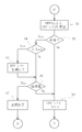
- FIG. 3 is a flowchart showing the operation of the storage battery 4 during charging.
- the relay contact piece 9 is on the storage battery side, the normally open contact piece 10 is open, and the power generation of the solar cell string 2 is sufficient for charging the storage battery 3.
- the ON duty of the switching cycle in which the switching element 8 is ON / OFF controlled so that the generated power of the solar cell string 2 is maximized in step S1 is based on MPPT (Maximum Power Point Tracking). Calculated. If this value is not charging in step S2, the process proceeds to step S3 and this value is set in the output unit.
- the switching element 8 is turned ON / OFF based on the set value. That is, the value of the ON duty is changed every cycle of this flowchart.
- step S4 determines whether or not the charging current I to the storage battery 4 exceeds the set current Iset. Then, the value of the ON duty calculated in step S1 is decreased by a predetermined value. That is, the voltage applied to the storage battery 4 is lowered and the charging current to the storage battery 4 is reduced.
- This set current Iset is arbitrarily set in consideration of the type, characteristics, and design of the storage battery 4.
- step S6 it is determined whether or not the storage battery 4 is fully charged. This determination of full charge is based on whether or not the terminal voltage of the storage battery 4 has reached a voltage indicating full charge or a voltage determined to be full charge set in advance, and if the charge capacity of the storage battery can be managed, the charge capacity is When the target charge capacity is reached, it is determined that the battery is fully charged.
- step S6 If the full charge is not determined in step S6, the process proceeds to step S3, and the ON duty value is set in the output section.
- step S7 charge termination processing is performed. That is, the relay contact piece 9 is switched to the power conversion device 3 side, and the determination during charging in step S2 is subsequently determined as “No”.
- the charging method of the storage battery 4 is not limited to such a charging method, and a charging method using a constant current or a charging method using a constant voltage can also be used.
- step S4 is changed to determination whether the applied voltage V of the storage battery 4 is not in the range of 360V to 400V. When this condition is satisfied, the value of the ON duty is corrected in step S5.
- the ON duty is increased, and when the applied voltage exceeds 400V, the ON duty is reduced.
- the process proceeds to step S6, and the storage battery 4 is determined to be fully charged.
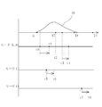
- FIG. 4 is an example of a time chart showing the driving operation, in which driving is performed by arbitrarily selecting the driving modes “mode A”, “mode B”, “mode C”, and “mode D”.
- Mode A is a mode that automatically charges the storage battery according to the power generation amount of the solar cell string
- Mode B is a mode in which an automatic discharge mode is added in addition to this automatic charging. This is indicated by “modes A and B”.
- Mode D is for starting the discharge of the storage battery 4 by closing the normally open contact piece 10 when this mode is selected or when a separate switch is operated in addition to this mode. This discharge is continued until the end of the discharge.
- mode C By using “mode C” and “mode D”, charging can be started at an arbitrary time by a leading operation and discharging can be started at an arbitrary time if a switch operation is taken into consideration.
- the selection of these modes and the operation of the switch can be configured so as to enable the remote operation using the operation in the main electrical box or the remote controller, and may be arbitrarily configured.
Landscapes
- Engineering & Computer Science (AREA)
- Power Engineering (AREA)
- Charge And Discharge Circuits For Batteries Or The Like (AREA)
- Control Of Electrical Variables (AREA)
Abstract
【課題】直流電力を交流電力へ変換する電力変換装置の前段に設けられ容易に蓄電池を利用したシステムを構成できるようにするものである。 【解決手段】太陽電池ストリング2の正極側と負極側との間に接続されるリアクタ5、ダイオード6、コンデンサ7の直列回路の当該リアクタ5、ダイオード6間を太陽電池ストリング2の負極側に導通させるスイッチング素子8を有する昇圧回路と、蓄電池4と、昇圧回路の前記コンデンサ7の正極側の端子から得られる昇圧回路の出力を蓄電池4側、又は蓄電池4側と異なり交流出力を出力させる電力変換装置3側に切り換える切換部9と、切換部9が昇圧回路の出力を蓄電池4側へ供給している際は蓄電池4の充電を行い、切換部9が昇圧回路の出力を電力変換装置3側へ供給している際は当該出力又は太陽電池の発 電電力が最大値又は最大値付近に収束するようにスイッチング素子8のON/OFFを制御する制御部27とを備える。
Description
本発明は太陽電池で発電されたエネルギーを系統に同期した交流電力に変換した後この系統へ重畳する電力変換装置の前段に用いられ太陽電池で発電されたエネルギーが経由する集電箱に関し、前記エネルギーを蓄電池に充電可能にする集電箱に関する。
近年、太陽電池で発電されたエネルギーを交流電力に変換して系統へ重畳する電力変換装置が普及している。この電力変換システムでは太陽電池の発電エネルギー量に依存して系統へ重畳される電力も変化するため、任意のタイミングでこの発電エネルギーを系統へ重畳するなどの活用ができないものであった。
そのため、電力変換装置内に蓄電池を設け、太陽電池の発電エネルギーをこの蓄電池に充電し任意のタイミングで放電して使用するものが考えられていた。(特許文献1参照)
システムでは、太陽電池(ストリング)で発電された電力がDC/DCコンバータで昇圧され、DC/ACコンバータで交流電力に変換された後、系統へ重畳されるように構成されていた。DC/DCコンバータとDC/ACコンバータとをつなぐ電力線にリレーなどの開閉器を介して蓄電池が接続され、この蓄電池の放電の際は蓄電池の充電電圧がそのままDC/ACコンバータに印加されていた。従って、蓄電池の放電エネルギーを系統へ重畳若しくは交流の独立電源として出力する際には、この蓄電池の出力電圧を昇圧(例えば、単相100Vの交流では約280V、単相200Vの交流では約560V)し安定化した後一般的なPWMに基づく疑似正弦波を生成する必要があるがDC/ACコンバータで昇圧を兼ねるにはその昇圧比が充分に取れない場合があり出力される交流電力の電圧が必要電圧に満たない場合があった。
よって、一般的には蓄電池の定格電圧を少なくともこの280V、560Vなど出力する交流電力に応じて構成する必要があり、蓄電池自体の大型化、高圧対策が必要となり小型のシステムには向かないものであった。
本発明の集電箱は、太陽電池セルを直列/並列に組み合わせた太陽電池ストリングの正極側と負極側との間に接続されるリアクタ、ダイオード、コンデンサの直列回路の当該リアクタ、ダイオード間を太陽電池ストリングの負極側に導通させるスイッチング素子を有する昇圧回路と、蓄電池と、昇圧回路のコンデンサの正極側の端子から得られる昇圧回路の出力を蓄電池側、又は当該蓄電池側と異なり交流出力を出力させる電力変換装置側に切り換える切換部と、当該切換部が昇圧回路の出力を前記蓄電池側へ供給している際は当該出力で前記蓄電池を交流のピーク電圧値の2倍超えない定格電圧に成るようにスイッチング素子のON/OFFを制御して当該蓄電池の充電を行い切換部が昇圧回路の出力を電力変換装置側へ供給している際は当該出力又は太陽電池の発電電力が最大値又は最大値付近に収束するように前記スイッチング素子のON/OFFを制御する制御部とを備えるものである。
また、本発明の集電箱はさらに、太陽電池ストリングをさらに接続可能に構成すると共に、このさらに接続される太陽電池ストリングの発電電力は昇圧回路と異なり同様の構成を有する昇圧回路を介して電力変換装置側へ接続されると共に、この昇圧回路は当該昇圧回路の出力又は太陽電池の発電電力が最大値又は最大値付近に収束するようにこの昇圧回路のスイッチング素子のON/OFFを制御する制御部とを備えるものである。
また、本発明の集電箱はさらに、切換部は予め定めた時刻に昇圧器の出力を蓄電池側又は電力変換装置側に切り替えると共に、昇圧器の出力が蓄電池側の際に当該蓄電池の所定量以上の充電を検知した際に切換部を電力変換装置側に切り替えるものである。
また、本発明の集電箱は、切換部はリレーの接片で構成されるものである。
また、本発明の集電箱は、電力変換装置は集電箱から出力される直流電力を昇圧回路で昇圧した後、インバータ回路部で交流電力に変換して出力させると共に、蓄電池の定格電圧はインバータ回路の入力電圧の1/2~2/3程度の電圧であるものである。
また、本発明の集電箱は、蓄電池の定格電圧は太陽電池ストリングの最大発電電圧を超えないものである。
また、切換部が昇圧回路の出力を蓄電池側へ供給している際は前記スイッチング素子のON/OFFを制御して当該蓄電池の定電圧充電を行うものである。
また、太陽電池セルを直列/並列に組み合わせた太陽電池ストリングの正極側と負極側との間に接続されるリアクタ、ダイオード、コンデンサの直列回路の当該リアクタ、ダイオード間を太陽電池ストリングの負極側に導通させるスイッチング素子を有する昇圧回路と、蓄電池と、昇圧回路の前記コンデンサの正極側の端子から得られる昇圧回路の出力を蓄電池側、又は当該蓄電池側と異なり交流出力を出力させる電力変換装置側に切り換える切換部と、当該切換部が昇圧回路の出力を蓄電池側へ供給している際は太陽電池ストリングの発電電力が最大となる電圧より所定電圧値低い電圧以上の電圧の範囲で太陽電池ストリングの当該出力又は太陽電池の発電電力が最大値又は最大値付近になるような電圧が蓄電池へ印加されるようにスイッチング素子のON/OFFを制御して当該蓄電池の充電を行い切換部が昇圧回路の出力を電力変換装置側へ供給している際は当該出力又は太陽電池の発電電力が最大値又は最大値付近に収束するようにスイッチング素子のON/OFFを制御する制御部とを備えると共に蓄電池の定格電圧が太陽電池ストリングの発電電力が最大となる電圧より所定電圧値低い電圧以下であるものである。
また、蓄電池の充電を行う際は、当該蓄電池へ印加される電圧が蓄電池の定格電圧に対し定電圧充電を行う際の設定最大電圧値を越えないようにスイッチング素子のON/OFFを制御部で制御するものである。
また、太陽電池セルを直列/並列に組み合わせた太陽電池ストリングの正極側と負極側との間に接続されるリアクタ、ダイオード、コンデンサの直列回路の当該リアクタ、ダイオード間を太陽電池ストリングの負極側に導通させるスイッチング素子を有する昇圧回路を複数収納しこれら複数の昇圧回路の出力を交流電力に変換して出力する電力変換装置へ供給可能に構成された集電箱において、蓄電池が接続可能な接続部と、複数の昇圧回路の内少なくとも1つの昇圧回路の出力を接続部側、又は電力変換装置側に切り換える切換部と、切換部とつながらない昇圧回路の出力を電力変換装置へのみ供給させる構成とを備えることを特徴とする集電箱。
本発明は、用いる蓄電池の定格電圧を下げ小規模なシステムでも汎用性を高めることができる集電箱を成したものである。
太陽電池の発電エネルギーを集電箱を介して蓄電池へ蓄電した後、電力変換装置はこの蓄電池の放電電力を昇圧した後交流電力に変換するので、蓄電池の定格電圧、すなわち放電電圧を低くすることができ、低電圧の汎用電池の組み合わせが可能になるものである。
図1は本発明の実施例を示す説明図であり、1は集電箱であり、太陽電池セル(図示せず)を複数個直列及び並列に組み合わせて所定の電圧と所定の出力が発電されるように成した太陽電池ストリング2から発電出力されたエネルギー(発電電力)を昇圧して電力変換装置3へ供給するか蓄電池4へ供給するかを切り替えることができるものである。
この太陽電池ストリング2は例えば家屋などの建物の屋根または屋上に南側に向けて設置されている。太陽電池ストリング2の発電電力は集電箱の正極端子Pにと負極端子Nとの間に出力され、端子Pと端子Nとの間にはリアクタ5、ダイオード6、コンデンサ7が直列に接続され、またリアクタ5とダイオード6との接続点と端子N(太陽電池ストリング2の負極側)との間にスイッチング素子が接続されている。
この太陽電池ストリング2は例えば家屋などの建物の屋根または屋上に南側に向けて設置されている。太陽電池ストリング2の発電電力は集電箱の正極端子Pにと負極端子Nとの間に出力され、端子Pと端子Nとの間にはリアクタ5、ダイオード6、コンデンサ7が直列に接続され、またリアクタ5とダイオード6との接続点と端子N(太陽電池ストリング2の負極側)との間にスイッチング素子が接続されている。
9は切り替え接片(切換部)でありダイオード6とコンデンサ7との接続点の出力を電力変換装置3の側若しくは蓄電池4の側のいずれかに切り替えるリレー接片であり、常閉状態(励磁されていない状態)で電力変換装置3の側であり、励磁状態で蓄電池4の側に切り替わるものである。10は常開接片であり励磁状態で蓄電池4の放電出力を電力変換装置3へ供給できるものである。
11は制御部であり、リレー接片9が電力変換装置3の側にあるときは、端子Pでの電圧と電流との積、すなわち太陽電池ストリング2の発電電力が最大になるようにスイッチング素子8をON/OFF制御しているスイッチング周期(例えば20Hz)のONデューティを可変するものである。この制御によりリアクタ5、ダイオード6、コンデンサ7、スイッチング素子8はDC/DCコンバータとして動作しその出力電圧はスイッチング素子に与えられるONデューティによって変わるものである。
リレー接片9が蓄電池4の側にあるときは、前記制御に加えて蓄電池4へ充電される電流が設定電流値を超えないようにまたは蓄電池4への印加電圧が設定電圧を超えないようにONデューティが補正(小さくなるように補正)される。また蓄電池4の端子電圧が設定電圧(満充電と判断する状態)に至った際に蓄電池4の充電を終了するものである。
電力変換装置3は正極入力端子Ppと負極入力端子Npとを備え、集電箱1の出力電力は端子Ppと端子Np間に供給される。端子Ppと端子Np間には集電箱1と同様にリアクタ12、ダイオード13、コンデンサ14、スイッチング素子15で構成されたDC/DCコンバータが接続されている。このDC/DCコンバータで昇圧された直流電力はスイッチング素子16~19で構成された単相ブリッジ回路(インバータ回路)でチョッピングされ擬似正弦波となりリアクタ20、21とコンデンサ22のローパスフィルターを経た後に交流電力に変換される。この交流電力は2連の常開接片23a、23b及び2連の切り替え接片24a、24bを介して系統25の電力ラインに重畳される。
この電力ラインを介して系統25の交流電力及び電力変換装置3から出力される交流電力が負荷へ供給されるものである。2連の切り替え接片24a、24bは系統25が停電の際や系統25とは連携せず単独で交流電力を負荷へ出力する際に常開接片側に切り替わり電力変換装置3の交流出力を独立コンセント26を介して出力するものである。
この電力ラインを介して系統25の交流電力及び電力変換装置3から出力される交流電力が負荷へ供給されるものである。2連の切り替え接片24a、24bは系統25が停電の際や系統25とは連携せず単独で交流電力を負荷へ出力する際に常開接片側に切り替わり電力変換装置3の交流出力を独立コンセント26を介して出力するものである。
27は電力変換装置3の制御部であり、系統の周波数と同じでありかつ系統と同期した擬似正弦波が得られるようにスイッチング素子16~19をPWM(pulse width modulation:パルス幅変調)制御に基づいてON/OFFさせるものであり、また系統25に重畳させる交流電力が最大になるように(系統の電圧は実質的に一定であるため、系統25に重畳させる交流電力の電流が最大になるように)DC/DCコンバータを構成するスイッチング素子15のONデューティを変える制御を行うものである。
例えば、系統25の電圧が単相200V(実効値)であれば、この交流電力の電圧波形はピーク電圧が約280Vの正弦波であり、当該正弦波を得るための擬似正弦波(ローパースフィルターの1次側)は直流560Vをチョッピングした波形である。従って、電力変換装置3から系統25へ交流電力を重畳させるには系統25の電圧(560V)以上の直流電圧を単相ブリッジ回路に印加する必要があり、この電力変換装置3のDC/DCコンバータの出力電圧には560V以上が必要になる。
尚、系統25への重畳させる電力を「0」にする必要が生じた場合はこのDC/DCコンバータの出力電圧は560V以下であれば良いがDC/DCコンバータの昇圧比は「1」以下とはならないため電力変換装置3の端子Ppと端子Npと間に供給される電圧は560V以下が好ましい。すなわち系統の交流のピーク電圧の2倍を超えない直流電圧が好ましい。また変換効率を重視しなければ、この電圧以下になるように降圧回路を設けることも可能である。
常開接片10を閉じると蓄電池4は電力変換装置3の端子Ppと端子Np間に接続されこれら端子間に放電が行われるが、これら端子間の電圧は系統の交流のピーク電圧の2倍を超えない値が好ましく、従って蓄電池4の定格電圧を、この蓄電池4の充電を終了する設定電圧とするとこの系統の交流のピーク電圧の2倍を超えない電圧が好ましい。例えば、太陽電池ストリング2からの充電を考慮し、この太陽電池ストリング2の定格電圧より高く560V以下の値で、蓄電池4の構成し易い値であり、例えば定格電圧は200V~450Vの程度が良く、両DC/DCコンバータの昇圧効率が良くなるような範囲で設定する。
尚、この電圧は一例であり系統の条件、太陽電池ストリングの条件、電力変換装置の条件等によって任意に設定されるものである。例えば、12Vの汎用電池があれば直列に25個接続した電圧が当てはまる。
28は蓄電池への充電機能を有さない集電箱であり太陽電池ストリングス29の発電力が最大になるように昇圧するDC/DCコンバータを集電箱1と同様な構成で備えるものである。30、31はそれぞれ集電箱28と同様な集電箱であり太陽電池ストリング32、33に繋がっている。集電箱28、30、31の出力は電力の逆流を防止するダイオード34を介して集電箱1の出力端子に接続されており、蓄電池4の放電が集電箱28、30、31へ流れることを防止している。すなわち、集電箱28、30、31のDC/DCコンバータ(昇圧回路)の出力を電力変換装置3へのみ供給させている。尚、このダイオード34は蓄電池4の集電箱28、30、31への放電を許容する際は省略することができるものである。
太陽電池ストリング2、29、32、33は例えば順に南側、東側、西側、北側のように平均日射量が多い順に対応させることが可能であり、北側に相当する太陽電池ストリングは省略することも可能である。また集電箱28を集電箱1と同等にして蓄電池への充電を可能に構成してもよい。尚、太陽電池ストリング2のみを用いて構成してもよいものである。
図2は他の実施例を示す説明図であり、図1との相違は図1に示す集電箱1、28、30、31を単一の筐体内に収納して1つの集電箱40としたものである。この集電箱40には図1に示した集電箱1、28、30、31の機能を備え同様の動作を行うものであり、集電箱40に機能をまとめることにより蓄電池を含めた施工性が向上するものである。
尚、図1に示した構成と同じ動作をするものは同じ記号を付して説明を省略する。
尚、図1に示した構成と同じ動作をするものは同じ記号を付して説明を省略する。
図3は蓄電池4の充電時の動作を示すフローチャートであり、リレー接片9が蓄電池側にあり、常開接片10が開状態であり太陽電池ストリング2の発電が蓄電池3の充電に充分である際に、ステップS1で太陽電池ストリング2の発電電力が最大になるようにスイッチング素子8をON/OFF制御しているスイッチング周期のONデューティをMPPT(Maximum Power Point Tracking)に基づいて新しい値が計算される。この値はステップS2で充電中でなければステップS3へ進み出力部にこの値がセットさせる。このセットされた値に基づいてスイッチング素子8のON/OFFが行われるものである。すなわちONデューティの値はこのフローチャートの1周期毎に変更されるものである。
ステップS2で蓄電池4が充電中である場合は、ステップS4へ進み、蓄電池4への充電電流Iが設定電流Isetを超えているか否かの判断を行い、ステップS4の条件を満たす際はステップS5へ進みステップS1で算出されたONデューティの値を所定値減らすものである。すなわち蓄電池4への印加電圧が低下し蓄電池4への充電電流が減少するものである。この設定電流Isetは蓄電池4の種類、特性、設計を考慮して任意に設定されるものである。
次いでステップS6で蓄電池4が満充電になっているか否かの判断を行うものである。この満充電の判断は蓄電池4の端子電圧が満充電を示す電圧、またはあらかじめ設定した満充電と判断する電圧に至ったか否か、さらには蓄電池の充電容量を管理できる場合にはその充電容量が目標充電容量に達した際に満充電と判断するものである。
ステップS6で満充電が判断されなかった場合はステップS3へ進みONデューティの値を出力部にセットする。満充電が判断された場合は、ステップS7へ進み充電終了の処理を行うものである。すなわちリレー接片9を電力変換装置3側へ切り替え、ステップS2の充電中の判断が以後「No」で判断させるものである。
尚、蓄電池4の充電方法はこのような充電方法に限るものではなく、定電流による充電方法や定電圧による充電方法などを用いることも可能である。
定電圧による充電を行う場合は、例えば、太陽電池ストリングの最大発電時の開放電圧が400Vとするとこの開放電圧の90%程度(太陽電池ストリングの出力に応じてこの限りではない。)の電圧になるように蓄電池4の定格電圧を構成する。この場合、定格12Vの汎用電池を30個直接に接続して蓄電池4を構成すれば、その定格電圧を360Vに構成することができる。図2に示すフローチャートにおいて、ステップS4を蓄電池4の印加電圧Vが360V~400Vの範囲にないかあるかの判断に変え、この条件を満たす際はステップS5でONデューティの値を補正する。印加電圧が360Vより低い場合はONデューティを増加させ、印加電圧が400Vを超えている場合はONデューティを減らす補正を行うものである。印加電圧が360V~400Vの範囲にあるときはステップS6へ進み、蓄電池4の満充電の判断を行うも用に構成する。
尚、ステップS4で蓄電池4を低電圧充電する際の最大電圧を太陽電池ストリング2の最大出力時の電圧と同じ400Vにしているがこれに限るものではなく太陽電池ストリング2の最大出力時の電圧はこれより低くてもよいものであり、前記各電圧値は太陽電池ストリングの構成(最大出力)や蓄電池の構成(定格電圧)などによって変わるものであり、その構成毎にそれぞれ設定されるものである。
図4は運転動作を示すタイムチャートの一例であり、運転モード「モードA」、「モードB」、「モードC」、「モードD」を任意に選択して運転が行われるものである。「モードA」は太陽電池ストリングの発電量に応じて自動的に蓄電池への充電を行うモードであり、「モードB」はこの自動充電に加えて自動放電を行うモードが加えたれたものであり「モードA、B」で示している。
1日の時刻に対する日射量の変化40に連動し、「モードA」では自動充電を行う時刻がt0~t2に設定されている。尚、t0の時刻は季節、地域によって任意に変更可能である。このt0の時刻では蓄電池4への充電を可能とする太陽電池ストリング2の出力がすでに得られているので時刻t0から充電が開始される。時刻t1で蓄電池4の満充電が判断され充電が終了している。尚、この充電動作は時刻t2を越えることはなく、充電が継続されている際は時刻t2でステップS7の満充電が強制的に判断され充電が終了するものである。また、時刻t0で太陽電池ストリング2の発電量が不十分のときは、発電量
が増加してから充電を開始するものである。
が増加してから充電を開始するものである。
「モードB」が選択されている際は、「モードA]での充電後の時刻t3から常開接片10が閉じられて蓄電池4の放電が開始される。時刻t4で蓄電池4の放電が終了している。すなわち蓄電池4の端子電圧が一定以下となり放電終了が判断され、または所定の放電量が判断された状態である。この放電を開始する時刻t3は任意に設定することができ、例えば午後2時、3時など夏場の電力消費が増加する時間帯に合わせると電力消費のピークカットが行えるものである。
「モードC」はこのモードを選択した時、またはこのモードに加えて別途スイッチを操作したときから充電を開始するものであり、満充電となり充電の終了する時刻t6まで充電が継続されるものである。尚、終了時刻には時刻t5から設定時間の上限を設けることも可能である。
「モードD」はこのモードを選択した時、またはこのモードに加えて別途スイッチを操作したときから常開接片10を閉じて蓄電池4の放電を開始するものである。この放電は放電終了まで継続されるものである。
「モードC」、「モードD」を用いることによって、スッチ操作を加味すれば主導操作で任意の時刻に充電を開始し、任意の時刻から放電を開始させることができるものである。
これらモードの選択、スイッチなどの操作は、主電箱での操作、またはリモートコントローラを用いて遠隔操作を可能とするように構成することも可能であり、任意に構成すればよい。
本発明に係る集電箱は、上記実施例に示した構成に限定されず、種々の形態のものに適用できるものであり、本発明の技術範囲において種々の形態を包含するものである。
1 集電箱
2 太陽電池ストリング
3 電力変換装置
4 蓄電池
5 リアクタ
6 ダイオード
7 コンデンサ
8 スイッチング素子
9 変換部
2 太陽電池ストリング
3 電力変換装置
4 蓄電池
5 リアクタ
6 ダイオード
7 コンデンサ
8 スイッチング素子
9 変換部
Claims (10)
- 太陽電池セルを直列/並列に組み合わせた太陽電池ストリングの正極側と負極側との間に接続されるリアクタ、ダイオード、コンデンサの直列回路の当該リアクタ、ダイオード間を前記太陽電池ストリングの負極側に導通させるスイッチング素子を有する昇圧回路と、蓄電池と、前記昇圧回路の前記コンデンサの前記正極側の端子から得られる前記昇圧回路の出力を前記蓄電池側、又は当該蓄電池側と異なり交流出力を出力させる電力変換装置側に切り換える切換部と、当該切換部が前記昇圧回路の出力を前記蓄電池側へ供給している際は当該出力で前記蓄電池を前記交流のピーク電圧値の2倍を超えない定格電圧に成るように前記スイッチング素子のON/OFFを制御して当該蓄電池の充電を行い前記切換部が前記昇圧回路の出力を前記電力変換装置側へ供給している際は当該出力又は太陽電池の発電電力が最大値又は最大値付近に収束するように前記スイッチング素子のON/OFFを制御する制御部とを備えることを特徴とする集電箱。
- 前記太陽電池ストリングをさらに接続可能に構成すると共に、このさらに接続される太陽電池ストリングの発電電力は前記昇圧回路と異なり同様の構成を有する昇圧回路を介して前記電力変換装置側へ接続されると共に、この昇圧回路は当該昇圧回路の出力又は太陽電池の発電電力が最大値又は最大値付近に収束するようにこの昇圧回路の前記スイッチング素子のON/OFFを制御する制御部とを備えることを特徴とする請求項1に記載の集電箱。
- 前記切換部は予め定めた時刻に前記昇圧器の出力を前記蓄電池側又は前記電力変換装置側に切り替えると共に、前記昇圧器の出力が前記蓄電池側の際に当該蓄電池の所定量以上の充電を検知した際に前記切換部を前記電力変換装置側に切り替えることを特徴とする請求項1又は請求項2のいずれか一方に記載の集電箱。
- 前記切換部はリレーの接片で構成されることを特徴とする請求項3に記載の集電箱。
- 前記電力変換装置は前記集電箱から出力される直流電力を昇圧回路で昇圧した後、インバータ回路部で交流電力に変換して出力させると共に、前記蓄電池の定格電圧は前記インバータ回路の入力電圧の1/2~2/3程度の電圧であることを特徴とする請求項1乃至請求項4のいずれか1項に記載の集電箱。
- 前記蓄電池の定格電圧は太陽電池ストリングの最大発電電圧を超えないことを特徴とする請求項5に記載の集電箱。
- 前記切換部が前記昇圧回路の出力を前記蓄電池側へ供給している際は前記スイッチング素子のON/OFFを制御して当該蓄電池の定電圧充電を行うことを特徴とする請求項1乃至請求項6のいずれかに記載の集電箱。
- 太陽電池セルを直列/並列に組み合わせた太陽電池ストリングの正極側と負極側との間に接続されるリアクタ、ダイオード、コンデンサの直列回路の当該リアクタ、ダイオード間を前記太陽電池ストリングの負極側に導通させるスイッチング素子を有する昇圧回路と、蓄電池と、前記昇圧回路の前記コンデンサの前記正極側の端子から得られる前記昇圧回路の出力を前記蓄電池側、又は当該蓄電池側と異なり交流出力を出力させる電力変換装置側に切り換える切換部と、当該切換部が前記昇圧回路の出力を前記蓄電池側へ供給している際は前記太陽電池ストリングの発電電力が最大となる電圧より所定電圧値低い電圧以上の電圧の範囲で前記太陽電池ストリングの当該出力又は太陽電池の発電電力が最大値又は最大値付近になるような電圧が前記蓄電池へ印加されるように前記スイッチング素子のON/OFFを制御して当該蓄電池の充電を行い前記切換部が前記昇圧回路の出力を前記電力変換装置側へ供給している際は当該出力又は太陽電池の発電電力が最大値又は最大値付近に収束するように前記スイッチング素子のON/OFFを制御する制御部とを備えると共に前記蓄電池の定格電圧が前記太陽電池ストリングの発電電力が最大となる電圧より所定電圧値低い電圧以下であることを特徴とする集電箱。
- 前記蓄電池の充電を行う際は、当該蓄電池へ印加される電圧が前記蓄電池の定格電圧に対し定電圧充電を行う際の設定最大電圧値を越えないように前記スイッチング素子のON/OFFを前記制御部で制御することを特徴とする請求項8に記載の集電箱。
- 太陽電池セルを直列/並列に組み合わせた太陽電池ストリングの正極側と負極側との間に接続されるリアクタ、ダイオード、コンデンサの直列回路の当該リアクタ、ダイオード間を前記太陽電池ストリングの負極側に導通させるスイッチング素子を有する昇圧回路を複数収納しこれら複数の昇圧回路の出力を交流電力に変換して出力する電力変換装置へ供給可能に構成された集電箱において、蓄電池が接続可能な接続部と、前記複数の昇圧回路の内少なくとも1つの昇圧回路の出力を前記接続部側、又は前記電力変換装置側に切り換える切換部と、前記切換部とつながらない昇圧回路の出力を前記電力変換装置へのみ供給させる構成とを備えることを特徴とする集電箱。
Priority Applications (1)
| Application Number | Priority Date | Filing Date | Title |
|---|---|---|---|
| JP2013516238A JP5895135B2 (ja) | 2011-05-24 | 2012-03-16 | 集電箱 |
Applications Claiming Priority (2)
| Application Number | Priority Date | Filing Date | Title |
|---|---|---|---|
| JP2011115926 | 2011-05-24 | ||
| JP2011-115926 | 2011-05-24 |
Publications (1)
| Publication Number | Publication Date |
|---|---|
| WO2012160864A1 true WO2012160864A1 (ja) | 2012-11-29 |
Family
ID=47216953
Family Applications (1)
| Application Number | Title | Priority Date | Filing Date |
|---|---|---|---|
| PCT/JP2012/056806 Ceased WO2012160864A1 (ja) | 2011-05-24 | 2012-03-16 | 集電箱 |
Country Status (2)
| Country | Link |
|---|---|
| JP (1) | JP5895135B2 (ja) |
| WO (1) | WO2012160864A1 (ja) |
Families Citing this family (1)
| Publication number | Priority date | Publication date | Assignee | Title |
|---|---|---|---|---|
| JP6519553B2 (ja) * | 2016-08-24 | 2019-05-29 | サンケン電気株式会社 | 太陽光発電システム |
Citations (3)
| Publication number | Priority date | Publication date | Assignee | Title |
|---|---|---|---|---|
| JP2003067065A (ja) * | 2001-08-28 | 2003-03-07 | Matsushita Electric Ind Co Ltd | バッテリ内蔵型電力変換装置 |
| JP2007133765A (ja) * | 2005-11-11 | 2007-05-31 | Sharp Corp | インバータ装置 |
| JP2011250673A (ja) * | 2010-04-26 | 2011-12-08 | Omron Corp | エネルギーコントローラおよび制御方法 |
-
2012
- 2012-03-16 JP JP2013516238A patent/JP5895135B2/ja not_active Expired - Fee Related
- 2012-03-16 WO PCT/JP2012/056806 patent/WO2012160864A1/ja not_active Ceased
Patent Citations (3)
| Publication number | Priority date | Publication date | Assignee | Title |
|---|---|---|---|---|
| JP2003067065A (ja) * | 2001-08-28 | 2003-03-07 | Matsushita Electric Ind Co Ltd | バッテリ内蔵型電力変換装置 |
| JP2007133765A (ja) * | 2005-11-11 | 2007-05-31 | Sharp Corp | インバータ装置 |
| JP2011250673A (ja) * | 2010-04-26 | 2011-12-08 | Omron Corp | エネルギーコントローラおよび制御方法 |
Also Published As
| Publication number | Publication date |
|---|---|
| JPWO2012160864A1 (ja) | 2014-07-31 |
| JP5895135B2 (ja) | 2016-03-30 |
Similar Documents
| Publication | Publication Date | Title |
|---|---|---|
| CN102170150B (zh) | 蓄电系统 | |
| JP5124114B2 (ja) | 蓄電機能を有するパワーコンディショナ | |
| JP5081596B2 (ja) | 電力供給システム | |
| JP4856069B2 (ja) | 三相ソーラー変換器回路および方法 | |
| US8907522B2 (en) | Grid-connected power storage system and method for controlling grid-connected power storage system | |
| Choe et al. | A Bi-directional battery charger for electric vehicles using photovoltaic PCS systems | |
| US9077202B1 (en) | Power converter with series energy storage | |
| US20110089886A1 (en) | Maximum Power Point Tracking Bidirectional Charge Controllers for Photovoltaic Systems | |
| WO2006112201A1 (ja) | 電源装置およびその制御方法 | |
| WO2012144358A1 (ja) | 電力供給装置、電力供給装置の制御方法、および直流給電システム | |
| JP2014128164A (ja) | パワーコンディショナ及び太陽光発電システム | |
| TW201251289A (en) | Integrated buck/boost converter of charging apparatus | |
| JP2020533931A (ja) | H5トポロジー構造を有するインバータ装置用の制御処理方法 | |
| JP5799210B2 (ja) | 蓄電システム、充放電回路、及び系統連系装置 | |
| JP2013165624A (ja) | 蓄電装置用パワーコンディショナ、蓄電装置 | |
| JP2009207234A (ja) | ハイブリッド系統連系システム | |
| KR101764651B1 (ko) | 태양광 발전 장치 연계형 전력공급장치 및 이의 제어 방법 | |
| US9142966B2 (en) | Method for controlling a grid-connected power supply system | |
| KR101130320B1 (ko) | 풍력발전장치의 대기전력 공급장치 | |
| Rasin et al. | Design and simulation of quasi-Z-source grid-connected PV inverter with bidirectional power flow for battery storage management | |
| JP2016201893A (ja) | 系統連系システム | |
| KR101587488B1 (ko) | 계통 연계형 시스템에서의 고효율 배터리 충방전 시스템 및 방법 | |
| JP5895143B2 (ja) | 蓄電装置 | |
| Andrade et al. | PV module-integrated single-switch DC/DC converter for PV energy harvest with battery charge capability | |
| JP5895135B2 (ja) | 集電箱 |
Legal Events
| Date | Code | Title | Description |
|---|---|---|---|
| 121 | Ep: the epo has been informed by wipo that ep was designated in this application |
Ref document number: 12789463 Country of ref document: EP Kind code of ref document: A1 |
|
| ENP | Entry into the national phase |
Ref document number: 2013516238 Country of ref document: JP Kind code of ref document: A |
|
| NENP | Non-entry into the national phase |
Ref country code: DE |
|
| 122 | Ep: pct application non-entry in european phase |
Ref document number: 12789463 Country of ref document: EP Kind code of ref document: A1 |