WO2012157381A1 - 作業機械のエンジン制御装置およびそのエンジン制御方法 - Google Patents
作業機械のエンジン制御装置およびそのエンジン制御方法 Download PDFInfo
- Publication number
- WO2012157381A1 WO2012157381A1 PCT/JP2012/060259 JP2012060259W WO2012157381A1 WO 2012157381 A1 WO2012157381 A1 WO 2012157381A1 JP 2012060259 W JP2012060259 W JP 2012060259W WO 2012157381 A1 WO2012157381 A1 WO 2012157381A1
- Authority
- WO
- WIPO (PCT)
- Prior art keywords
- engine
- speed
- target
- assist
- output
- Prior art date
- Legal status (The legal status is an assumption and is not a legal conclusion. Google has not performed a legal analysis and makes no representation as to the accuracy of the status listed.)
- Ceased
Links
Images










Classifications
-
- B—PERFORMING OPERATIONS; TRANSPORTING
- B60—VEHICLES IN GENERAL
- B60W—CONJOINT CONTROL OF VEHICLE SUB-UNITS OF DIFFERENT TYPE OR DIFFERENT FUNCTION; CONTROL SYSTEMS SPECIALLY ADAPTED FOR HYBRID VEHICLES; ROAD VEHICLE DRIVE CONTROL SYSTEMS FOR PURPOSES NOT RELATED TO THE CONTROL OF A PARTICULAR SUB-UNIT
- B60W10/00—Conjoint control of vehicle sub-units of different type or different function
- B60W10/04—Conjoint control of vehicle sub-units of different type or different function including control of propulsion units
- B60W10/06—Conjoint control of vehicle sub-units of different type or different function including control of propulsion units including control of combustion engines
-
- F—MECHANICAL ENGINEERING; LIGHTING; HEATING; WEAPONS; BLASTING
- F02—COMBUSTION ENGINES; HOT-GAS OR COMBUSTION-PRODUCT ENGINE PLANTS
- F02D—CONTROLLING COMBUSTION ENGINES
- F02D31/00—Use of speed-sensing governors to control combustion engines, not otherwise provided for
- F02D31/001—Electric control of rotation speed
-
- F—MECHANICAL ENGINEERING; LIGHTING; HEATING; WEAPONS; BLASTING
- F02—COMBUSTION ENGINES; HOT-GAS OR COMBUSTION-PRODUCT ENGINE PLANTS
- F02D—CONTROLLING COMBUSTION ENGINES
- F02D29/00—Controlling engines, such controlling being peculiar to the devices driven thereby, the devices being other than parts or accessories essential to engine operation, e.g. controlling of engines by signals external thereto
- F02D29/06—Controlling engines, such controlling being peculiar to the devices driven thereby, the devices being other than parts or accessories essential to engine operation, e.g. controlling of engines by signals external thereto peculiar to engines driving electric generators
-
- B—PERFORMING OPERATIONS; TRANSPORTING
- B60—VEHICLES IN GENERAL
- B60W—CONJOINT CONTROL OF VEHICLE SUB-UNITS OF DIFFERENT TYPE OR DIFFERENT FUNCTION; CONTROL SYSTEMS SPECIALLY ADAPTED FOR HYBRID VEHICLES; ROAD VEHICLE DRIVE CONTROL SYSTEMS FOR PURPOSES NOT RELATED TO THE CONTROL OF A PARTICULAR SUB-UNIT
- B60W10/00—Conjoint control of vehicle sub-units of different type or different function
- B60W10/04—Conjoint control of vehicle sub-units of different type or different function including control of propulsion units
- B60W10/08—Conjoint control of vehicle sub-units of different type or different function including control of propulsion units including control of electric propulsion units, e.g. motors or generators
-
- B—PERFORMING OPERATIONS; TRANSPORTING
- B60—VEHICLES IN GENERAL
- B60W—CONJOINT CONTROL OF VEHICLE SUB-UNITS OF DIFFERENT TYPE OR DIFFERENT FUNCTION; CONTROL SYSTEMS SPECIALLY ADAPTED FOR HYBRID VEHICLES; ROAD VEHICLE DRIVE CONTROL SYSTEMS FOR PURPOSES NOT RELATED TO THE CONTROL OF A PARTICULAR SUB-UNIT
- B60W20/00—Control systems specially adapted for hybrid vehicles
-
- E—FIXED CONSTRUCTIONS
- E02—HYDRAULIC ENGINEERING; FOUNDATIONS; SOIL SHIFTING
- E02F—DREDGING; SOIL-SHIFTING
- E02F9/00—Component parts of dredgers or soil-shifting machines, not restricted to one of the kinds covered by groups E02F3/00 - E02F7/00
- E02F9/20—Drives; Control devices
- E02F9/2058—Electric or electro-mechanical or mechanical control devices of vehicle sub-units
- E02F9/2062—Control of propulsion units
- E02F9/2075—Control of propulsion units of the hybrid type
-
- E—FIXED CONSTRUCTIONS
- E02—HYDRAULIC ENGINEERING; FOUNDATIONS; SOIL SHIFTING
- E02F—DREDGING; SOIL-SHIFTING
- E02F9/00—Component parts of dredgers or soil-shifting machines, not restricted to one of the kinds covered by groups E02F3/00 - E02F7/00
- E02F9/20—Drives; Control devices
- E02F9/22—Hydraulic or pneumatic drives
- E02F9/2278—Hydraulic circuits
- E02F9/2292—Systems with two or more pumps
-
- E—FIXED CONSTRUCTIONS
- E02—HYDRAULIC ENGINEERING; FOUNDATIONS; SOIL SHIFTING
- E02F—DREDGING; SOIL-SHIFTING
- E02F9/00—Component parts of dredgers or soil-shifting machines, not restricted to one of the kinds covered by groups E02F3/00 - E02F7/00
- E02F9/20—Drives; Control devices
- E02F9/22—Hydraulic or pneumatic drives
- E02F9/2278—Hydraulic circuits
- E02F9/2296—Systems with a variable displacement pump
-
- F—MECHANICAL ENGINEERING; LIGHTING; HEATING; WEAPONS; BLASTING
- F02—COMBUSTION ENGINES; HOT-GAS OR COMBUSTION-PRODUCT ENGINE PLANTS
- F02D—CONTROLLING COMBUSTION ENGINES
- F02D29/00—Controlling engines, such controlling being peculiar to the devices driven thereby, the devices being other than parts or accessories essential to engine operation, e.g. controlling of engines by signals external thereto
-
- F—MECHANICAL ENGINEERING; LIGHTING; HEATING; WEAPONS; BLASTING
- F02—COMBUSTION ENGINES; HOT-GAS OR COMBUSTION-PRODUCT ENGINE PLANTS
- F02D—CONTROLLING COMBUSTION ENGINES
- F02D45/00—Electrical control not provided for in groups F02D41/00 - F02D43/00
-
- B—PERFORMING OPERATIONS; TRANSPORTING
- B60—VEHICLES IN GENERAL
- B60W—CONJOINT CONTROL OF VEHICLE SUB-UNITS OF DIFFERENT TYPE OR DIFFERENT FUNCTION; CONTROL SYSTEMS SPECIALLY ADAPTED FOR HYBRID VEHICLES; ROAD VEHICLE DRIVE CONTROL SYSTEMS FOR PURPOSES NOT RELATED TO THE CONTROL OF A PARTICULAR SUB-UNIT
- B60W2300/00—Indexing codes relating to the type of vehicle
- B60W2300/17—Construction vehicles, e.g. graders, excavators
-
- B—PERFORMING OPERATIONS; TRANSPORTING
- B60—VEHICLES IN GENERAL
- B60W—CONJOINT CONTROL OF VEHICLE SUB-UNITS OF DIFFERENT TYPE OR DIFFERENT FUNCTION; CONTROL SYSTEMS SPECIALLY ADAPTED FOR HYBRID VEHICLES; ROAD VEHICLE DRIVE CONTROL SYSTEMS FOR PURPOSES NOT RELATED TO THE CONTROL OF A PARTICULAR SUB-UNIT
- B60W2710/00—Output or target parameters relating to a particular sub-units
- B60W2710/06—Combustion engines, Gas turbines
- B60W2710/0644—Engine speed
-
- F—MECHANICAL ENGINEERING; LIGHTING; HEATING; WEAPONS; BLASTING
- F02—COMBUSTION ENGINES; HOT-GAS OR COMBUSTION-PRODUCT ENGINE PLANTS
- F02D—CONTROLLING COMBUSTION ENGINES
- F02D31/00—Use of speed-sensing governors to control combustion engines, not otherwise provided for
- F02D31/001—Electric control of rotation speed
- F02D31/007—Electric control of rotation speed controlling fuel supply
-
- Y—GENERAL TAGGING OF NEW TECHNOLOGICAL DEVELOPMENTS; GENERAL TAGGING OF CROSS-SECTIONAL TECHNOLOGIES SPANNING OVER SEVERAL SECTIONS OF THE IPC; TECHNICAL SUBJECTS COVERED BY FORMER USPC CROSS-REFERENCE ART COLLECTIONS [XRACs] AND DIGESTS
- Y02—TECHNOLOGIES OR APPLICATIONS FOR MITIGATION OR ADAPTATION AGAINST CLIMATE CHANGE
- Y02T—CLIMATE CHANGE MITIGATION TECHNOLOGIES RELATED TO TRANSPORTATION
- Y02T10/00—Road transport of goods or passengers
- Y02T10/10—Internal combustion engine [ICE] based vehicles
- Y02T10/40—Engine management systems
-
- Y—GENERAL TAGGING OF NEW TECHNOLOGICAL DEVELOPMENTS; GENERAL TAGGING OF CROSS-SECTIONAL TECHNOLOGIES SPANNING OVER SEVERAL SECTIONS OF THE IPC; TECHNICAL SUBJECTS COVERED BY FORMER USPC CROSS-REFERENCE ART COLLECTIONS [XRACs] AND DIGESTS
- Y02—TECHNOLOGIES OR APPLICATIONS FOR MITIGATION OR ADAPTATION AGAINST CLIMATE CHANGE
- Y02T—CLIMATE CHANGE MITIGATION TECHNOLOGIES RELATED TO TRANSPORTATION
- Y02T10/00—Road transport of goods or passengers
- Y02T10/60—Other road transportation technologies with climate change mitigation effect
- Y02T10/62—Hybrid vehicles
Definitions
- the present invention relates to an engine control device for a work machine including a construction machine such as a hydraulic excavator, a bulldozer, a dump truck, a wheel loader, and the engine control method.
- a construction machine such as a hydraulic excavator, a bulldozer, a dump truck, a wheel loader, and the engine control method.
- engine controller In engine control of a diesel engine (hereinafter referred to as an engine) used in a work machine, when an operator of the work machine arbitrarily sets a fuel adjustment dial (throttle dial) provided in the cab, the engine controller is connected to the fuel injection system. On the other hand, a control signal for injecting the fuel injection amount corresponding to the setting to the engine is output. The engine controller then outputs to the fuel injection system a control signal corresponding to the load fluctuation of the work machine attached to the work machine so that the target engine speed set by the fuel adjustment dial (throttle dial) is maintained. Then adjust the engine speed. Further, the engine controller or the pump controller calculates a target absorption torque of the hydraulic pump according to the engine target rotational speed. This target absorption torque is set so that the output horsepower of the engine and the absorption horsepower of the hydraulic pump are balanced.
- the engine is controlled so as not to exceed the engine output torque line TL, which is composed of the engine maximum output torque line P1 and the engine droop line Fe drawn from the maximum engine speed.
- the engine controller for example, when the work machine is a hydraulic excavator or the like, determines the engine speed according to the operation amount of the operation lever operated for the turning operation of the upper-part turning body and the work machine operation and the load of the work machine etc.
- a control signal is generated for changing. For example, when excavation operation such as earth and sand is performed in a state where the engine target rotational speed is set to N2, the engine rotational speed when the engine is idling (idling rotational speed N1) is changed to the engine target rotational speed N2.
- the fuel injection system receives a control signal from the engine controller, injects fuel into the engine in accordance with this transition, and when the load increases due to operation of the work implement etc., the engine speed and engine output torque
- the engine speed shifts so that a matching point M1 corresponding to the intersection of the pump absorption torque line PL of the variable displacement hydraulic pump (typically a swash plate hydraulic pump) and the engine output torque line TL is reached. To do. At the rated point P, the engine output becomes maximum.
- a target engine operation line (target matching route) ML passing through a region with a good fuel consumption rate is provided, and this target matching route is provided.
- an engine control device that provides a matching point between the engine output and the pump absorption torque on the ML.
- a curve M shows an iso-fuel consumption curve of the engine, and the fuel consumption rate is more excellent as it goes to the center of the curve M (eyeball (M1)).
- Curve J represents an equal horsepower curve in which the horsepower absorbed by the hydraulic pump is equal horsepower.
- the fuel consumption rate is better when matching is performed at the matching point pt2 on the target matching route ML than when matching is performed at the matching point pt1 on the engine droop line Fe.
- a construction machine such as a hybrid hydraulic excavator in which the upper swing body is driven by an electric swing motor.
- electric power is supplied (discharged) from a power storage device such as a capacitor to the electric swing motor to accelerate the upper swing body, and when the upper swing body is rotated and decelerated, the electric swing motor regenerates power to the capacitor. Is supplied (charged) to achieve a lower fuel consumption rate than conventional hydraulic excavators.
- the generator driven by the engine in response to the load of the working machine, the generator driven by the engine is caused to generate power (power generation on), and the electric power generated by the generator is supplied to the capacitor (charging).
- the electric power generated by the generator is supplied for turning acceleration of the electric turning motor.
- the generator performs an assist operation to supplement the output of the engine according to the load of the hybrid excavator, and achieves a low fuel consumption rate.
- the engine speed before starting the work machine operation is the matching point MP0, which is a low idling speed, low load, small swash plate angle of the hydraulic pump, and pump capacity. It is in the lowest state.
- the pump capacity of the hydraulic pump cannot be increased immediately, but gradually increases, so immediately increase the engine speed to ensure the amount of hydraulic fluid discharged from the hydraulic pump.
- the target matching rotational speed (target assist rotational speed) np1 is controlled so that the engine rotational speed is low.
- the present invention has been made in view of the above, and is an engine of a working machine capable of sufficiently ensuring the responsiveness of the working machine by the assisting action of the engine by the generator while improving the fuel consumption and the pump efficiency. It is an object of the present invention to provide a control device and an engine control method thereof.
- an engine control device for a work machine includes an engine, a generator that assists the output of the engine, and a detection unit that detects an operating state of the work machine. And, based on the operating state, a no-load maximum rotational speed calculating means for calculating a maximum no-load rotational speed that is the maximum engine speed when the load is released, and based on the operating state , Target matching speed calculation means for calculating the target matching speed, which is the engine speed that is increased when a load is applied, separately from the no-load maximum speed, and maximum output based on the operating state Engine target output calculation means for calculating an engine target output that can be performed, and under the limitation of the engine target output, the no-load maximum rotation speed and the target matching rotation speed An engine control means for controlling the engine speed, an assist determination means for determining that an assist is required when a deviation between the target matching speed and the current engine speed exceeds a predetermined value; After it is determined that it is necessary, the target
- the assist rotational speed setting means sets the target assist rotational speed to an upper limit for a predetermined time from a point in time when the assist is determined to be necessary.
- the target assist rotational speed is set, and after a predetermined time has elapsed, the target assist rotational speed is set to decrease the engine rotational speed to the target matching rotational speed at a predetermined rotational speed reduction rate.
- the engine control device for a work machine further includes load calculation means for calculating an engine load based on the detection result of the detection means in the above invention, wherein the assist rotation speed setting means is the upper limit.
- the target assist rotational speed is set to decrease in accordance with an increase in the engine load at or below the target assist rotational speed.
- the upper limit target assist rotational speed is an engine rotational speed at an intersection of the no-load maximum rotational speed droop line and the target matching route. It is characterized by that.
- the engine control device for a work machine is characterized in that, in the above invention, the predetermined value of the deviation is determined according to an operating state of the work machine.
- the engine control method for a work machine includes a detection step for detecting an operation state of the work machine, and an engine speed that is maximized when a load is released based on the operation state.
- the no-load maximum rotation speed calculation step for calculating the no-load maximum rotation speed, and the target matching rotation speed that is the engine speed that is increased when a load is applied based on the operation state
- a target matching rotation speed calculation step that is calculated separately, an engine target output calculation step that calculates an engine target output that can be maximized based on the operating state, and under the limitation of the engine target output,
- An engine control step for controlling an engine speed between the no-load maximum speed and the target matching speed; and the target matching speed
- An assist determination step for determining that an assist is required when a deviation from a current engine speed exceeds a predetermined value; and after determining that an assist is required, a target assist speed is determined based on the target matching
- the assist rotation speed setting step sets the target assist rotation speed to an upper limit for a predetermined time from the time when it is determined that the assist is necessary.
- the target assist rotational speed is set, and after a predetermined time has elapsed, the target assist rotational speed is set to decrease the engine rotational speed to the target matching rotational speed at a predetermined rotational speed reduction rate.
- the engine control method for a work machine includes a load calculation step of calculating an engine load based on a detection result of the detection means in the above invention, wherein the assist rotation speed setting step includes the upper limit
- the target assist rotational speed is set to decrease in accordance with an increase in the engine load at or below the target assist rotational speed.
- the target assist rotational speed is set to a predetermined upper limit target assist rotational speed that is larger than the target matching rotational speed, and then gradually.
- the target assist speed close to the target matching speed is set, and the engine speed is controlled by outputting an assist torque command value to the generator so that the engine speed becomes the target assist speed. Therefore, the responsiveness of the work implement can be sufficiently ensured by the assisting action of the generator while improving the fuel consumption and the pump efficiency.
- FIG. 1 is a perspective view showing an overall configuration of a hybrid excavator according to an embodiment of the present invention.
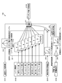
- FIG. 2 is a schematic diagram showing a configuration of a control system of the hybrid excavator shown in FIG.
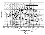
- FIG. 3 is a torque diagram for explaining the contents of engine control by the controller.
- FIG. 4 is a torque diagram for explaining the contents of engine control by the controller.
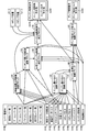
- FIG. 5 is a diagram showing an overall control flow by the controller.
- FIG. 6 is a diagram showing a detailed control flow of the no-load maximum rotation speed calculation block shown in FIG.
- FIG. 7 is a diagram showing a detailed control flow of the engine minimum output calculation block shown in FIG.
- FIG. 8 is a diagram showing a detailed control flow of the engine maximum output calculation block shown in FIG.
- FIG. 6 is a diagram showing a detailed control flow of the no-load maximum rotation speed calculation block shown in FIG.
- FIG. 7 is a diagram showing a detailed control flow of the engine minimum output calculation block shown in FIG
- FIG. 9 is a diagram showing a detailed control flow of the engine target output calculation block shown in FIG.
- FIG. 10 is a diagram showing a detailed control flow of the matching minimum rotation speed calculation block shown in FIG.
- FIG. 11 is a diagram showing a detailed control flow of the target matching rotation speed calculation block shown in FIG.
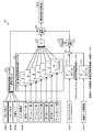
- FIG. 12 is a diagram showing a detailed control flow of the engine speed command value calculation block shown in FIG.
- FIG. 13 is a diagram showing a detailed control flow of the pump absorption torque command value calculation block shown in FIG.
- FIG. 14 is a torque diagram for explaining the contents of engine control by the controller.
- FIG. 15 is a torque diagram showing a setting state of the target matching rotational speed when power generation is turned on / off.
- FIG. 15 is a torque diagram showing a setting state of the target matching rotational speed when power generation is turned on / off.
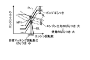
- FIG. 16 is a torque diagram showing a state of engine output variation due to pump variation in conventional engine control.
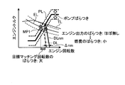
- FIG. 17 is a torque diagram showing a state of engine output variation due to pump variation in the embodiment of the present invention.
- FIG. 18 is a torque diagram showing an engine output transition state at the time of transition in conventional engine control.
- FIG. 19 is a torque diagram showing an engine output transition state at the time of transition in the embodiment of the present invention.
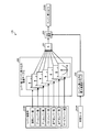
- FIG. 20 is a diagram illustrating a flow for determining the assist state.
- FIG. 21 is a time chart showing assist control at the start of work implement operation according to the embodiment of the present invention.
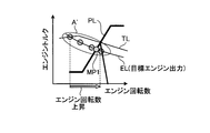
- FIG. 22 is a torque diagram showing changes in the operating point of the engine by the assist control shown in FIG. FIG.
- FIG. 23 is a diagram illustrating a control flow for setting the target assist rotational speed.
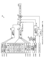
- FIG. 24 is a diagram illustrating a flow of calculating the assist torque from the target assist rotation speed.
- FIG. 25 is a diagram showing another setting control flow of the target assist rotation speed.
- FIG. 26 is a torque diagram illustrating conventional engine control.
- FIG. 27 is a torque diagram illustrating conventional engine control using a target matching route.
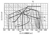
- FIG. 28 is a torque diagram showing the operating point of the engine by the conventional assist control at the start of work implement operation.
- FIG. 29 is a torque diagram showing an operating point of the engine by another conventional assist control at the start of the work machine operation.
- FIG. 1 and FIG. 2 have shown the whole structure of the hybrid hydraulic shovel 1 which is an example as a working machine.
- the hybrid excavator 1 includes a vehicle body 2 and a work implement 3.
- the vehicle main body 2 includes a lower traveling body 4 and an upper swing body 5.
- the lower traveling body 4 has a pair of traveling devices 4a.
- Each traveling device 4a has a crawler belt 4b.
- Each traveling device 4a travels or turns the hybrid excavator 1 by driving the crawler belt 4b with a right traveling motor and a left traveling motor (traveling motor 21).
- the upper turning body 5 is provided on the lower traveling body 4 so as to be turnable, and turns when the turning motor 24 is driven.
- the upper swing body 5 is provided with a cab 6.
- the upper swing body 5 includes a fuel tank 7, a hydraulic oil tank 8, an engine room 9, and a counterweight 10.
- the fuel tank 7 stores fuel for driving the engine 17.
- the hydraulic oil tank 8 stores hydraulic oil discharged from the hydraulic pump 18 to a hydraulic cylinder such as the boom cylinder 14 and hydraulic equipment such as the traveling motor 21.
- the engine room 9 houses devices such as the engine 17 and the hydraulic pump 18.
- the counterweight 10 is disposed behind the engine chamber 9.
- the work machine 3 is attached to the front center position of the upper swing body 5 and includes a boom 11, an arm 12, a bucket 13, a boom cylinder 14, an arm cylinder 15, and a bucket cylinder 16.
- a base end portion of the boom 11 is rotatably connected to the upper swing body 5. Further, the distal end portion of the boom 11 is rotatably connected to the proximal end portion of the arm 12.
- the tip of the arm 12 is rotatably connected to the bucket 13.
- the boom cylinder 14, the arm cylinder 15, and the bucket cylinder 16 are hydraulic cylinders that are driven by hydraulic oil discharged from the hydraulic pump 18.
- the boom cylinder 14 operates the boom 11.
- the arm cylinder 15 operates the arm 12.
- the bucket cylinder 16 operates the bucket 13.
- the hybrid excavator 1 includes an engine 17, a hydraulic pump 18, and a generator 19 as drive sources.
- a diesel engine is used as the engine 17, and a variable displacement hydraulic pump (for example, a swash plate hydraulic pump) is used as the hydraulic pump 18.
- a hydraulic pump 18 and a generator 19 are mechanically coupled to the output shaft of the engine 17, and the hydraulic pump 18 and the generator 19 are driven by driving the engine 17.
- the generator 19 may be mechanically coupled directly to the output shaft of the engine 17 or may be rotationally driven via a transmission means such as a belt or chain applied to the output shaft of the engine 17.
- the hydraulic drive system includes a control valve 20, a boom cylinder 14, an arm cylinder 15, a bucket cylinder 16, a traveling motor 21, and the like, and a hydraulic pump 18 is driven as a hydraulic source.
- the electric drive system includes a capacitor 22, an inverter 23, and a turning motor 24.
- the electric power generated by the generator 19 or the electric power discharged from the capacitor 22 is supplied to the turning motor 24 via the power cable to turn the upper turning body 5. That is, the turning motor 24 is driven to turn by the electric power supplied (electric power generation) supplied from the generator 19 or the electric energy supplied (discharged) from the capacitor 22, and the turning motor 24 is turned when the turning is decelerated. Electric energy is supplied (charged) to the capacitor 22 by the regenerative action.
- an SR switched reluctance
- the generator 19 is mechanically coupled to the output shaft of the engine 17, and the rotor shaft of the generator 19 is rotated by driving the engine 17.
- an electric double layer capacitor is used as the capacitor 22.
- a nickel metal hydride battery or a lithium ion battery may be used.
- the rotation motor 25 is provided with a rotation sensor 25, detects the rotation speed of the rotation motor 24, converts it into an electric signal, and outputs it to a hybrid controller 23a provided in the inverter 23.
- a hybrid controller 23a As the turning motor 24, for example, an embedded magnet synchronous motor is used.
- a resolver or a rotary encoder is used as the rotation sensor 25.
- the hybrid controller 23a includes a CPU (an arithmetic device such as a numerical arithmetic processor), a memory (a storage device), and the like.
- the hybrid controller 23a receives a signal of a detection value by a temperature sensor such as a thermistor or a thermocouple provided in the generator 19, the swing motor 24, the capacitor 22 and the inverter 23, and overheats each device such as the capacitor 22. In addition, the charging / discharging control of the capacitor 22, the power generation / engine assist control by the generator 19, and the power running / regeneration control of the turning motor 24 are performed.
- a temperature sensor such as a thermistor or a thermocouple provided in the generator 19
- the swing motor 24 the capacitor 22 and the inverter 23, and overheats each device such as the capacitor 22.
- the charging / discharging control of the capacitor 22, the power generation / engine assist control by the generator 19, and the power running / regeneration control of the turning motor 24 are performed.
- the hydraulic drive system and the electric drive system are driven according to the operation of operation levers 26 such as a work machine lever, a travel lever, and a turning lever provided in a cab 6 provided in the vehicle body 2.
- the operation amount of the operation lever 26 is converted into an electric signal by the lever operation amount detection unit 27.
- the lever operation amount detection unit 27 is configured by a pressure sensor. The pressure sensor detects the pilot oil pressure generated according to the operation of the operation lever, and the lever operation amount is obtained by converting the voltage output from the pressure sensor into the lever operation amount.
- the lever operation amount is output to the pump controller 33 as an electrical signal.
- the lever operation amount detection unit 27 is constituted by an electric detection means such as a potentiometer, and converts a voltage generated according to the lever operation amount into a lever operation amount. To obtain the lever operation amount.
- a fuel adjustment dial (throttle dial) 28 and a mode switching unit 29 are provided in the cab 6.
- the fuel adjustment dial (throttle dial) 28 is a switch for setting the fuel supply amount to the engine 17, and the set value of the fuel adjustment dial (throttle dial) 28 is converted into an electrical signal and output to the engine controller 30. Is done.
- the engine controller 30 includes an arithmetic device such as a CPU (numerical arithmetic processor) and a memory (storage device).
- the engine controller 30 generates a control command signal based on the set value of the fuel adjustment dial (throttle dial) 28, and the common rail control unit 32 receives the control signal to adjust the fuel injection amount to the engine 17.
- the engine 17 is an engine that can be electronically controlled by a common rail type, can output a target output by appropriately controlling the fuel injection amount, and can output at a certain engine speed. Torque can be set freely.
- the mode switching unit 29 is a part for setting the work mode of the hybrid excavator 1 to a power mode or an economy mode, and is configured by, for example, operation buttons and switches provided in the cab 6 or a touch panel. The operator can switch the work mode by operating those operation buttons.
- the power mode is a work mode that performs engine control and pump control with reduced fuel consumption while maintaining a large amount of work.
- the economy mode secures the operating speed of the work equipment 3 with light load work while further reducing fuel consumption. This is an operation mode in which engine control and pump control are performed.
- an electrical signal is output to the engine controller 30 and the pump controller 33.
- the output torque of the engine 17 and the absorption torque of the hydraulic pump 18 are matched in a region where the rotation speed and output torque of the engine 17 are relatively high.
- matching is performed with a lower engine output than in the power mode.
- the pump controller 33 receives signals transmitted from the engine controller 30, the mode switching unit 29, and the lever operation amount detection unit 27, controls the tilt of the swash plate angle of the hydraulic pump 18, and controls the hydraulic oil from the hydraulic pump 18. A control command signal for adjusting the discharge amount is generated.
- the pump controller 33 receives a signal from a swash plate angle sensor 18 a that detects the swash plate angle of the hydraulic pump 18. When the swash plate angle sensor 18a detects the swash plate angle, the pump displacement of the hydraulic pump 18 can be calculated.
- a pump pressure detection unit 20 a for detecting the pump discharge pressure of the hydraulic pump 18 is provided. The detected pump discharge pressure is converted into an electrical signal and input to the pump controller 33.
- the engine controller 30 and the pump controller 33 are connected via an in-vehicle LAN such as a CAN (Controller Area Network) so that information can be exchanged between them.
- the engine controller 30 acquires information such as a lever operation amount, a work mode, a turning speed, and a setting value of a fuel adjustment dial (throttle dial) 28 (a signal indicating an operation state) to obtain an engine output command value.
- the engine output command value is a constant horsepower curve (engine output command value curve) EL on the torque diagram, and is a curve that limits engine output.
- the engine output is not restrained by the droop line, and the engine output and the hydraulic pump output at the intersection (matching point) MP1 between the engine output command value curve EL and the pump absorption torque line PL. And the work machine 3 is operated.
- the matching point MP1 is preferably provided on the target matching route ML.
- the engine speed at the target matching point MP1 is the target matching speed np1, for example, in the vicinity of 1000 rpm in FIG. As a result, the work machine 3 can obtain a sufficient output, and the engine 17 is driven at a low speed, so that fuel consumption can be kept low.
- the engine controller 30 has a no-load maximum rotation speed np2 (for example, in the vicinity of 2050 rpm in FIG. 3) corresponding to information such as the lever operation amount, the rotation speed of the upper swing body 5 and the setting value of the fuel adjustment dial (throttle dial) And engine droop is controlled within the engine speed range between the target matching speed np1 and the no-load maximum speed np2, and the engine 17 is driven.
- np2 for example, in the vicinity of 2050 rpm in FIG. 3
- engine droop is controlled within the engine speed range between the target matching speed np1 and the no-load maximum speed np2, and the engine 17 is driven.
- the hydraulic fluid flow rate discharged from the hydraulic pump 18 can be sufficiently supplied to the hydraulic cylinders 14, 15, 16, and the operating speed of the work machine 3 can be ensured. Further, since the engine output is limited by the engine output command value curve EL, useless energy is not consumed.
- the no-load maximum rotation speed np2 is not limited to the maximum rotation speed that can be output by the engine.
- the hydraulic oil flow rate is required. Therefore, the droop line DL is shifted to a high rotation range to increase the engine speed, and the pump capacity is higher than the predetermined value. If it is detected that the flow rate is small, the flow rate of the hydraulic oil is not required, so the droop line DL is shifted to the low rotation range to lower the engine speed. By performing such control, it is possible to suppress wasteful fuel consumption due to engine driving in a high rotation range.
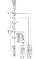
- FIG. 5 shows an overall control flow by the engine controller 30 or the pump controller 33.
- the engine controller 30 or the pump controller 33 finally calculates an engine speed command value and an engine output command value as engine control commands, and calculates a pump absorption torque command value as a pump control command.
- the no-load maximum rotation speed calculation block 110 calculates the no-load maximum rotation speed D210 (np2), which is a value that becomes the upper limit value of the engine rotation speed command value, according to the detailed control flow shown in FIG.
- D210 no-load maximum rotation speed
- the flow rate of the hydraulic pump 18 hydroaulic pump discharge flow rate
- the flow rate of the hydraulic pump 18 hydroaulic pump discharge flow rate
- the summation unit 212 obtains the total number of rotations obtained from each lever value signal D100 (lever operation amount) as a candidate value for the no-load maximum rotation number D210.
- Each lever value signal D100 (signal indicating each lever operation amount) includes a turning lever value, a boom lever value, an arm lever value, a bucket lever value, a traveling right lever value, a traveling left lever value, and a service lever value.
- This service lever value is a value indicating a lever operation amount for operating this hydraulic actuator when a hydraulic circuit to which a new hydraulic actuator can be connected is provided.
- Each lever value signal is converted into a no-load rotation speed by a lever value / no-load rotation speed conversion table 211 as shown in FIG. 6, and the total no-load rotation speed obtained by the summation unit 212 is obtained from the converted value.
- the data is output to the minimum value selection unit (MIN selection) 218.
- the no-load rotation speed limit value selection block 210 includes an operation amount of each operation lever value signal D100, pump pressures D105 and D106 which are discharge pressures of the hydraulic pump 18, and a work mode D104 set by the mode switching unit 29. Using the four pieces of information, the operator of the hybrid excavator 1 determines what operation pattern (work pattern) is currently being executed, and selects the no-load rotation speed limit value for the preset operation pattern. And decide. The determined no-load rotation speed limit value is output to the minimum value selection unit 218. For example, when the arm lever is tilted in the excavation direction and the pump pressure is higher than a certain set value, the hybrid excavator 1 is about to perform heavy excavation work.
- the hybrid excavator 1 determines that the hoist swing operation is about to be performed.
- the determination of the operation pattern is to estimate the operation that the operator is about to perform at that time.
- the hoist turning operation is an operation in which the upper turning body 5 is turned while raising the boom 11 with the earth and sand excavated by the bucket 13 and the earth and sand in the bucket 13 is discharged at a desired turning stop position.
- a candidate value for the no-load maximum rotational speed is also determined from the setting state (setting value) of the fuel adjustment dial 28 (throttle dial D103). That is, in response to a signal indicating the set value of the fuel adjustment dial 28 (throttle dial D103), the set value is converted into a no-load maximum rotation speed candidate value by the throttle dial / no-load rotation speed conversion table 213, and the minimum value The data is output to the selection unit 218.
- the hybrid hydraulic excavator 1 equipped with the electrically driven turning motor 24 does not require hydraulic pressure as a turning drive source. For this reason, among the hydraulic oil discharged from the hydraulic pump 18, the hydraulic oil discharge flow rate from the hydraulic pump 18 corresponding to the turning drive may be reduced. Accordingly, from the set value of the fuel adjustment dial 28 (throttle dial D103) and the no-load rotation speed obtained by the throttle dial / no-load rotation speed conversion table 213, the rotation motor rotation speed / no-load rotation speed is reduced from the rotation motor rotation speed D101. The no-load rotation speed reduction amount obtained by the amount conversion table 214 is reduced by the subtraction unit 215, and the obtained rotation speed is set as a candidate value for the no-load maximum rotation speed D210.
- the maximum value selection unit (MAX selection) 217 has a no-load rotation speed reduction amount larger than the no-load maximum rotation speed obtained from the set value of the fuel adjustment dial 28 (throttle dial D103), and the maximum value selection unit 217 The result of passing through the minimum value selection unit (MIN selection) 218 for comparison with the no-load rotation speed limit value output from the no-load rotation speed limit value selection block 210 when the input value becomes a negative value.
- the maximum value selection unit 217 selects the maximum value with the zero value 216 so that the no-load maximum rotation speed does not become a negative value, and the minimum value selection unit 218 is prevented from being given a negative value.
- the minimum value selection unit 218 determines the no-load rotational speed obtained from the lever value signal D100, the no-load rotational speed limit value obtained by the no-load rotational speed limit value selection block 210, and the no-rotation speed obtained from the swing motor rotational speed D101.
- the minimum value is selected from the three values of the no-load rotational speed obtained from the setting value of the throttle dial D103 in consideration of the load rotational speed limit value, and the no-load maximum rotational speed D210 (np2) is output.
- FIG. 7 is a detailed control flow of the engine minimum output calculation block 120.
- the engine minimum output calculation block 120 calculates an engine minimum output D220 that is a value that is a lower limit of the engine output command value.
- the lever value / engine minimum output conversion table 220 converts each lever value signal D100 to the engine minimum output in the same manner as the calculation of the no-load maximum rotation speed, and the summation unit 221 converts these sums into the minimum value selection unit (MIN selection unit). ) Output to 223.
- MIN selection unit minimum value selection unit
- the maximum value selection block 222 of the engine minimum output outputs the upper limit value corresponding to the work mode D104 set by the mode switching unit 29 to the minimum value selection unit 223.
- the minimum value selection unit 223 compares the sum of the engine minimum outputs corresponding to each lever value signal D100 and the upper limit value corresponding to the work mode D104, selects the minimum value, and outputs it as the engine minimum output D220.
- FIG. 8 is a detailed control flow of the engine maximum output calculation block 130.
- the engine maximum output calculation block 130 calculates an engine maximum output D230, which is a value that is an upper limit of the engine output command value.
- the pump output limit value selection block 231 uses the operation amount of each lever value signal D100 and the information on the set values of the pump pressures D105 and D106 and the work mode D104, similarly to the calculation by the no-load maximum rotation number calculation block 110.
- the current operation pattern is determined, and a pump output limit value is selected for each operation pattern.
- the adder 238 adds the fan horsepower calculated by the fan horsepower calculation block 234 to the selected pump output limit value from the engine rotation speed D108 detected by a rotation speed sensor (not shown).
- the turning horsepower calculation block 230 calculates the turning horsepower using the turning motor rotation speed D101 and the turning motor torque D102 as input parameters
- the fan horsepower calculation block 234 calculates the fan horsepower using the engine rotation speed D108.
- the turning horsepower and the fan horsepower are added to the pump output limit value via the subtraction unit 237 and the addition unit 238, respectively.
- the generator output D109 of the generator 19 is added to the pump output limit value via the subtraction unit 237.
- added values hereinafter referred to as added values
- the minimum value selection unit 239 selects the minimum value from the addition value and the engine output limit value, and outputs the minimum value as the engine maximum output D230.
- the fan is a fan provided in the vicinity of the radiator for cooling the engine 17, and blows air toward the radiator, and is driven to rotate in conjunction with the drive of the engine 17. .
- the hybrid hydraulic excavator 1 uses the turning motor 24 that is electrically driven by a driving source called electricity different from the driving source called the engine 17, it is necessary to obtain the turning horsepower and subtract the turning amount from the pump output limit value.
- the generator 19 When the generator 19 generates electric power, the sign of the value is defined as negative, and the minimum value selection unit 233 compares the value with the zero value 232, and the generator output is compared with the pump output limit value. Thus, since a negative value is subtracted, it is substantially an addition.
- the generator 19 assists the output of the engine 17, the value of the generator output is positive.
- the generator 19 generates power, since the generator output is a negative value, after selecting the minimum value with the zero value 232, the negative generator output is substantially subtracted from the pump output limit.
- the generator output is added to the pump output limit. That is, addition is performed only when the generator output D109 becomes a negative value.
- the assist of the engine 17 by the generator 19 is performed in order to increase the responsiveness of the work machine 3 when it is necessary to increase the engine speed from a certain predetermined speed to a high speed. If the output for the assist of the engine 17 is removed as an output, the responsiveness of the work machine 3 is not improved, and therefore the engine maximum output is not reduced just because the engine 17 is assisted. That is, even if a positive generator output is input to the minimum value selection unit 233, zero is output from the minimum value selection unit 233 by the minimum value selection with the zero value 232.
- the engine maximum output D230 is obtained without subtraction from the pump output limit.
- FIG. 9 is a detailed control flow of the engine target output calculation block 140.
- the engine target output calculation block 140 calculates an engine target output D240.
- the subtraction unit 243 subtracts the engine output addition offset value 241 set as a fixed value from the previous engine target output D240 obtained by the previous calculation.
- the subtraction unit 244 calculates a deviation obtained by subtracting the actual engine output calculated by the actual engine output calculation block 242 from the subtracted value.
- the multiplier 245 multiplies the deviation by a certain gain ( ⁇ Ki), and the integrator 246 integrates the multiplied value.
- the adder 247 adds the engine minimum output D220 calculated by the engine minimum output calculation block 120 to the integral value.
- the minimum value selection unit (MIN selection) 248 outputs, as the engine target output D240, the minimum value of the added value and the engine maximum output D230 calculated by the engine maximum output calculation block 130.
- the engine target output D240 is used as an engine output command value of the engine control command as shown in FIG. 5, and the engine target output D240 means the engine output command value curve EL shown in FIG. 3 or FIG.
- FIG. 10 is a detailed control flow of the matching minimum rotational speed calculation block 150.
- the minimum matching speed calculation block 150 calculates a minimum matching speed D150, which is the engine speed that must be increased at the minimum during work.
- a minimum matching speed D150 For the minimum matching rotation speed D150, each value obtained by converting each lever value signal D100 in the lever value / matching minimum rotation speed conversion table 251 becomes a candidate value for the minimum matching rotation speed D150, and each maximum value selection unit (MAX selection) 257 is used. Is output.
- MAX selection maximum value selection unit
- the no-load rotational speed / matching rotational speed conversion table 252 matches the engine rotational speed at the intersection of the droop line DL and the target matching route ML that intersect at the no-load maximum rotational speed np2, similarly to the target matching rotational speed np1.
- the rotation speed np2 ′ the no-load maximum rotation speed D210 (np2) obtained by the no-load maximum rotation speed calculation block 110 is converted and output (see FIG. 14).
- the low-speed offset rotational speed is subtracted from the matching rotational speed np2 ', and a value obtained as a result is output to the maximum value selection unit (MAX selection) 257 as a candidate value for the matching minimum rotational speed D150.
- MAX selection maximum value selection unit
- the swing motor rotation speed / matching minimum rotation speed conversion table 250 converts the swing motor rotation speed D101 as a candidate value of the matching minimum rotation speed D150 and outputs the converted value to the maximum value selection unit 257.
- the rotation motor rotation speed D101 is a value obtained by detecting the rotation motor rotation speed (speed) of the rotation motor 24 of FIG. 2 with a rotation sensor such as a resolver or a rotary encoder. Note that, as shown in FIG. 10, the turning motor rotation speed / matching minimum rotation speed conversion table 250 increases the minimum matching rotation speed when the rotation motor rotation speed D101 is zero, and increases as the rotation motor rotation speed D101 increases.
- the swing motor rotational speed D101 is converted with such a characteristic that the minimum matching rotational speed is reduced.
- the limit value of the torque that can be output to the maximum (generator maximum torque) is set for the generator 19, it is necessary to increase the engine speed in order to generate power with a somewhat large output. For this reason, the engine speed that must be increased at a minimum from the magnitude of the generator output that is required at any time is obtained using the generator output / matching speed conversion table 256, and the obtained engine speed. Is output to the maximum value selection unit (MAX selection) 257 as a candidate value for the minimum matching rotation speed D150. Note that the gate 255 arranged at the subsequent stage of the generator output D109 is provided to convert the generator output D109 into a positive value because the generator output D109 is negative.
- the maximum value selection unit 257 selects the maximum value among these minimum matching rotation speeds and outputs it as the minimum matching rotation speed D150.
- the engine speed when the load is removed, the engine speed increases up to the maximum no-load speed np2, and when the load is sufficient, the engine speed reaches the target matching speed np1. Go down.
- the engine speed greatly varies depending on the load. This large fluctuation in the engine speed may be perceived by the operator as a sense of discomfort (a feeling of lack of power) that the operator of the hybrid excavator 1 feels that the power of the hybrid excavator 1 is not exerted. Therefore, as shown in FIG. 14, it is possible to eliminate the uncomfortable feeling by using the low-speed offset rotational speed and changing the fluctuation range of the engine rotational speed depending on the magnitude of the set low-speed offset rotational speed.
- the low-speed offset rotational speed is reduced, the fluctuation range of the engine rotational speed is reduced, and if the low-speed offset rotational speed is increased, the fluctuation range of the engine rotational speed is increased.
- the operating state of the hybrid excavator 1 such as a state where the upper swing body 5 is turning and a state where the work implement 3 is performing excavation work
- the operator does not feel that the power is insufficient even if the engine speed is slightly lower than in the state where the work machine 3 is performing excavation work.
- HP1 to HP5 correspond to the equal horsepower line J shown in FIG. 27, ps indicates the horsepower unit (ps), and the horsepower increases as it goes to HP1 to HP5.
- An equal horsepower curve (engine output command value curve) EL is obtained and set according to the obtained engine output command value. Accordingly, the equal horsepower curve (engine output command value curve) EL is not limited to five HP1 to HP5, and is selected from among them.
- FIG. 14 shows a case where an equal horsepower curve (engine output command value curve) EL, whose horsepower is between 3 HP and 4 ps, is obtained and set.
- FIG. 11 is a detailed control flow of the target matching rotation speed calculation block 160.
- the target matching rotational speed calculation block 160 calculates the target matching rotational speed np1 (D260) shown in FIG.
- the target matching speed D260 is an engine speed at which the engine target output D240 (engine output command value curve EL) and the target matching route ML intersect. Since the target matching route ML is set so as to pass through a point where the fuel consumption rate is good when the engine 17 operates at a certain engine output, the target matching route ML is intersected with the engine target output D240 on the target matching route ML. It is preferable to determine the rotational speed D260.
- the engine target output / target matching rotation speed conversion table 267 receives the engine target output D240 (engine output command value curve EL) obtained by the engine target output calculation block 140 and receives the engine target output D240 (engine The target matching rotational speed at the intersection of the output command value curve EL) and the target matching route ML is obtained and output to the maximum value selection unit (MAX selection) 269.
- MAX selection maximum value selection unit
- the minimum matching speed D150 is obtained from the engine target output / target matching speed conversion table. It becomes larger than the matching rotational speed obtained in 267. Therefore, the maximum value selection unit (MAX selection) 269 compares the minimum matching rotation speed D150 with the matching rotation speed obtained from the engine target output D240, selects the maximum value, and sets it as a candidate value for the target matching rotation speed D260. Thus, the lower limit of the target matching rotational speed is limited.
- MAX selection compares the minimum matching rotation speed D150 with the matching rotation speed obtained from the engine target output D240, selects the maximum value, and sets it as a candidate value for the target matching rotation speed D260.
- the target matching route ML is deviated, but the target matching point is not MP1 but MP1 ′, and the target matching rotational speed D260 is not np1 but np1 ′.
- the upper limit of the target matching rotation speed D260 is also limited by the set value of the fuel adjustment dial 28 (throttle dial D103).
- the throttle dial / target matching rotation speed conversion table 268 receives the set value of the fuel adjustment dial 28 (throttle dial D103) and receives a droop line corresponding to the set value of the fuel adjustment dial 28 (throttle dial D103) ( The target matching rotational speed converted into the matching rotational speed at the intersection of the target matching route ML and the droop line that can be subtracted from the engine rotational speed corresponding to the set value of the fuel adjustment dial 28 (throttle dial D103) on the torque diagram.
- the candidate value of D260 is output, and the candidate value of the output target matching rotation number D260 and the candidate value of the target matching rotation number D260 selected by the maximum value selection unit 269 are the minimum value selection unit (MIN selection) 270. And the minimum value is selected and the final target map Ring rotational speed D260 is output.
- MIN selection minimum value selection unit
- the target matching rotational speed D260 is basically the rotational speed at the intersection of the engine target output and the target matching route ML, but the engine maximum output D230 is a fan output limit value as shown in FIG. It is a value obtained by adding the horsepower and the generator output, and the engine target output D240 is determined using the engine maximum output D230 as shown in FIG. Further, as shown in FIG. 11, the engine target output D240 is input to the target matching rotation speed calculation block 160, and the target matching rotation speed D260 is determined. Further, the value of the target matching rotational speed D260 changes depending on the generator output D109 required by the generator 19.
- the generator 19 is inefficient when it generates power with a small power generation torque. For this reason, when the power generator 19 performs power generation, control is performed so that power generation is performed at a preset minimum power generation torque or more. As a result, when the generator 19 is switched from a state where power is not generated (power generation is off) to a state where power is generated (power generation is on), power generation is switched on and off at the minimum power generation torque, so that the generator output changes discontinuously. . That is, since the matching point is determined at the intersection of the engine target output D240 and the target matching route ML, the target matching rotational speed D260 is increased by switching the power generation on / off in accordance with the discontinuous change in the generator output D109. It will fluctuate.
- Minimum power generation output (kW) 2 ⁇ ⁇ 60 ⁇ engine speed ⁇ minimum power generation torque (value is set to a negative value) ⁇ 1000
- the engine target output / target matching rotational speed conversion table 267 calculates the target matching rotational speed as a candidate value, thereby preventing the rotational speed fluctuation caused by power generation on / off.
- the minimum value selection unit (MIN selection) 262 following the generator output D109 has a zero value 261 in order to perform zero output when there is no required generator output (for example, when assisting the output of the engine 17). Compare with. Therefore, nothing is added to the engine target output D240. Further, the maximum value selection unit (MAX selection) 265 does not need to be added to the engine target output D240 because there is no shortage of the minimum power generation output when the required generator output is equal to or higher than the minimum power generation output. Therefore, a negative value is input to the maximum value selection unit 265, the maximum value zero is selected by comparison with the zero value 264, and the maximum value selection unit 265 outputs zero.
- FIG. 12 is a detailed control flow of the engine speed command value calculation block 170.
- the engine speed command value calculation block 170 is based on the pump capacities D110 and D111 obtained based on the swash plate angles detected by the swash plate angle sensors 18a of the two hydraulic pumps 18.
- the average unit 271 calculates an average pump capacity obtained by averaging the pump capacities D110 and D111, and the engine speed command selection block 273 generates an engine speed command value D270 (no-load maximum) according to the size of the average pump capacity.
- the rotation speed np2) is obtained.
- the engine speed command selection block 273 causes the engine speed command value D270 to approach the no-load maximum speed np2 (D210) when the average pump capacity is larger than a certain set value (threshold value). That is, the engine speed is increased.
- the average pump capacity is smaller than a certain set value, the engine speed is reduced so as to approach an engine speed nm1 described later.
- the engine speed corresponding to the position where the engine torque is reduced to zero along the droop line from the intersection of the target matching speed np1 (D260) and the torque on the target matching point MP1 is defined as the no-load speed np1a.
- the engine speed nm1 is obtained as a value obtained by adding the lower limit speed offset value ⁇ nm to the no-load speed np1a.
- the conversion to the no-load rotation speed corresponding to the target matching rotation speed D260 is performed by the matching rotation speed / no-load rotation speed conversion table 272. Therefore, the engine speed command value D270 is determined between the no-load minimum speed nm1 and the no-load maximum speed np2 depending on the pump capacity state.
- the lower limit rotational speed offset value ⁇ nm is a preset value and is stored in the memory of the engine controller 30.
- the set value q_com1 is a preset value and is stored in the memory of the pump controller 33.
- the set value q_com1 may be divided into an engine speed increasing side and an engine speed decreasing side, and two different set values may be provided to provide a range in which the engine speed does not change.
- FIG. 13 is a detailed control flow of the pump absorption torque command value calculation block 180.
- the pump absorption torque command value calculation block 180 obtains a pump absorption torque command value D280 using the current engine speed D108, engine target output D240, and target matching speed D260.
- the fan horsepower calculation block 280 calculates the fan horsepower using the engine speed D108.
- the fan horsepower is obtained using the above-described calculation formula.
- the subtraction unit 283 inputs an output (pump target absorption horsepower) obtained by subtracting the obtained fan horsepower from the engine target output D240 obtained in the engine target output calculation block 140 to the pump target matching rotation speed and torque calculation block 284. To do.
- the fan horsepower not only the fan horsepower but also the output (pump target absorption horsepower) obtained by subtracting the generator output D109 from the engine target output D240 is output to the pump target matching rotation speed and torque calculation block 284.
- the minimum value is selected by comparison with the zero value 281 in the minimum value selection unit (MIN selection) 282, and the selected value is calculated by the calculation unit.
- the addition to the engine target output D240 by 283 effectively subtracts the generator output D109 from the engine target output D240.
- the target matching rotation speed D260 obtained by the target matching rotation speed calculation block 160 is further input to the target matching rotation speed and torque calculation block 284.
- the target matching rotational speed D260 is the target matching rotational speed of the hydraulic pump 18 (pump target matching rotational speed).
- Pump target matching torque (60 x 1000 x (engine target output-fan horsepower)) / (2 ⁇ x target matching speed) Is calculated.
- the obtained pump target matching torque is output to the pump absorption torque calculation block 285.
- Pump absorption torque calculation block 285 receives pump target matching rotation speed and pump target matching torque output from torque calculation block 284, engine rotation speed D108 detected by the rotation sensor, and target matching rotation speed D260.
- pump absorption torque pump target matching torque ⁇ Kp ⁇ (target matching rotation speed ⁇ engine rotation speed) Is calculated, and a pump absorption torque command value D280 as a calculation result is output.
- Kp is a control gain.
- the target matching rotation speed D260 calculated by the target matching rotation speed calculation block 160 is an engine output command indicating an engine target output D240 when power generation is off, as shown in FIG.
- the intersection of the value curve ELa and the target matching route ML becomes the target matching point Ma, and at that time, the target matching rotation speed npa.
- the engine output command value curve ELb indicating the engine target output D240 for satisfying the minimum power generation output Pm is obtained, and the intersection of the engine output command value curve ELb and the target matching route ML. Becomes the target matching point Mb, at which time it becomes the target matching rotational speed npa ′.
- the target matching points Ma and Mb are frequently shifted by turning on / off the power generation.
- the target matching speed also changes frequently.
- the target matching rotation speed may vary depending on on / off of power generation. Absent.
- the target matching point when power generation is off is the intersection Ma ′ between the engine output command value curve ELa and the target matching rotational speed npa ′. Therefore, if the engine control shown in FIG.
- the matching point shifts as Ma ⁇ Mb ⁇ Mc as the generator output increases.
- the generator output increases.
- the matching point shifts in the order of Ma ′ ⁇ Mb ⁇ Mc, and there is no change in the target matching rotational speed when the generator output is such that the power generation is switched on and off, and the operator of the hybrid excavator 1 may feel uncomfortable. Disappear.
- Engine rotation speed command value rotation speed np1a obtained by converting target matching rotation speed np1 into no-load rotation speed + lower limit rotation speed offset value ⁇ nm
- the engine droop line is set at a high rotational speed with a minimum rotational speed offset value ⁇ nm added to the target matching rotational speed.
- the engine output is limited on the engine output command value curve EL and the engine target output is controlled to be constant, so that the actual absorption torque (pump actual absorption torque) is Even if variations occur in the pump absorption torque command, it is possible to reduce the fluctuation of the engine output.
- the fuel efficiency specification is, for example, a specification in which the fuel efficiency can be reduced by 10% compared to a conventional hybrid excavator.
- the intersection of the pump absorption torque line PL and the target matching rotational speed is set as the target matching point MP1
- the droop is accompanied accordingly.
- Variations in engine output also increase on line DL.
- the intersection of the pump absorption torque line PL and the engine output command value curve EL that is an equihorse power curve and indicates the upper limit of the engine output is a target matching.
- the target matching point MP1 varies along the engine output command value curve EL even when the variation in sequential performance of the hydraulic pump is large as the point MP1. For this reason, there is almost no variation in engine output, and as a result, there is almost no variation in fuel consumption.
- the capacitor 22 accumulates (charges) the electric energy generated by the regenerative action when the swing motor 24 is decelerated, and accumulates (charges) the electric energy generated by the generator 19.
- the engine 17 can be accelerated (assisted) by supplying (discharging) the accumulated electrical energy to the generator 19 according to the scene of work.
- Engine controller 30 first determines whether assistance to engine 17 is necessary or not by an assist state determination unit shown in FIG.
- the deviation calculation unit 310 obtains a rotational speed deviation ⁇ n obtained by subtracting the current engine rotational speed n from the target matching rotational speed np1.
- the current engine speed n is detected by a rotation sensor (not shown).
- the assist determination unit 320 determines and outputs an assist state D330 based on the deviation ⁇ n.
- the assist flag is set to “1”, and the assist state is set to be assisting.
- the assist flag is set to “0” and the assist flag is not set.
- Set the assist state to assist. That is, hysteresis characteristics are given to the setting of the assist state.
- the assist determination unit 320 forcibly determines that no assist is being performed when the electrical energy accumulated in the capacitor 22 is equal to or less than a predetermined value.
- sufficient responsiveness of the work implement 3 is ensured when shifting from the non-assist assist state before starting the work implement operation to the assist state during assist after the start of the work implement operation. Assist control is performed. That is, the responsiveness of the work implement at the time of rising from the non-assist assist state to the assist state during assist is sufficiently ensured.
- the engine controller 30 sets the target assist rotational speed AN to the target matching rotational speed as shown in FIG. 21 (a).
- a predetermined upper limit target assist rotational speed (high rotational target matching rotational speed) hAN larger than np1 is set.
- the engine controller 30 continues to set the high rotation target matching rotation speed hAN as the target assist rotation speed for a predetermined period T1 determined in advance from the time point t1. This predetermined period T1 is timed by a timer.
- the target assist rotational speed AN is decreased to the target matching rotational speed np1 at a predetermined rotational speed decrease rate ANr.
- the rotational speed reduction rate ANr is the amount of rotational speed (rpm) to be reduced per unit time. Note that a curve Ln in FIG. 21 (a) shows a temporal change in the actual engine speed.
- the target matching is determined from the engine speed at the matching point MP0 (state (1) in FIGS. 21 and 22) immediately after the start of the work operation and before the start of the work operation. Without being affected by the rotational speed np1, it rapidly increases to the high rotational target matching rotational speed hAN (state (2) in FIGS. 21 and 22). Thereafter, the high rotation target matching rotation speed hAN is maintained for a predetermined period T1, and the target assist rotation speed AN is temporarily set to the target matching rotation speed after the predetermined period T1 has elapsed (the state of (3) in FIGS. 21 and 22). It decreases to np1 and stabilizes at the target matching point MP1 as the load increases (state (4) in FIGS. 21 and 22). That is, the engine speed changes as shown by the arrow A3 and reaches the target matching point MP1.
- the assist state D330 is input to the determination units S101 and S102 from the assist state determination unit.
- the determination unit S101 outputs “T” to the switch SW1 if the assist state D330 is assisting and is within the predetermined period T1 from the time point t1 when the assist is being performed, and “F” if the predetermined period T1 has elapsed. Output to switch SW1.
- the determination unit S102 outputs “T” to the switch SW2 if the assist state D330 is assisting, and outputs “F” to the switch SW2 if not assisting.
- the switch SW1 receives a rotational speed obtained by subtracting the rotational speed reduction rate ANr (D310) from the target assist rotational speed AN (D320) fed back every minute time to the “F” terminal, and the high rotational target matching rotational speed hAN. (D311) is input to the “T” terminal. Therefore, the switch SW1 outputs the high rotation target matching rotation speed hAN (D311) to the “T” terminal of the switch SW2 within the predetermined period T1, and gradually decreases the rotation speed after the predetermined period T1 has elapsed. The target assist rotational speed decreased at the rate ANr (D310) is output to the “T” terminal.
- the switch SW2 In the switch SW2, the output from the switch SW1 is input to the “T” terminal, and the target matching rotational speed np1 (D260) is input to the “F” terminal. Therefore, the switch SW2 outputs one of the rotation speeds input from the switch SW1 when assisting, and outputs the target matching rotation speed np1 when not assisting. Then, the maximum value selection unit (MAX selection) 101 outputs the larger one of the rotation speeds input from the switch SW2 and the target matching rotation speed np1 to the minimum value selection unit (MIN selection) 102. The minimum value selection unit 102 outputs the smaller one of the input rotation speed and the high rotation target matching rotation speed hAN as the target assist rotation speed AN.
- MAX selection maximum value selection unit
- MIN selection minimum value selection unit
- the rotation speed between the high rotation target matching rotation speed hAN and the target matching rotation speed np1 is output as the target assist rotation speed AN (D230). Then, the change of the output of the target assist speed AN with the passage of time becomes like the waveform of the target assist speed shown in FIG.
- the target assist rotational speed AN set in this way is input to an assist torque calculation unit in the hybrid controller 23a shown in FIG.
- the assist torque calculation unit first subtracts the current engine speed n (D108) from the inputted target assist speed AN (D320) (calculation of the speed difference).
- the maximum value selection unit (MAX selection) 201 outputs the larger of the subtracted number of rotations and the zero value to the calculator 202.
- the comparison with the zero value is because there is no need to assist when the current engine speed n exceeds the target assist speed AN.
- the computing unit 202 multiplies the input rotational speed difference by the assist gain Kas and outputs an assist torque D340 converted into a torque value.
- the hybrid controller 23a assists the output of the engine 17 by supplying (discharging) the electrical energy accumulated in the capacitor 22 to the generator 19 according to the calculated assist torque D340.
- the target assist rotation speed AN is set to the high rotation target matching rotation speed hAN for a predetermined period T1 immediately after the assist is being performed, and after the predetermined period T1, the target matching rotation speed np1 is gradually decreased. I am doing so. Since such assist control is performed, high responsiveness of the work machine 3 can be ensured and useless energy consumption can be suppressed.
- the target assist speed AN (D320) may be set based on the engine load state as shown in FIG.
- the engine load is actually the pump load of the hydraulic pump 18.
- the target assist rotational speed AN (D320) is decreased, and when the pump load is small, the target assist rotational speed AN ( D320) is to be set large.
- the computing unit 302 multiplies the output obtained by subtracting the above-described engine load from the engine target output D240 by the gain Kp and outputs a value converted into the rotation speed.
- the converted value is added to the input target matching rotation speed np1 (D260), and the added rotation speed is input to the maximum value selection unit (MAX selection) 303.
- Maximum value selection section 303 outputs the larger of target matching rotation speed np1 (D260) and the added rotation speed to minimum value selection section (MIN selection) 304.
- the minimum value selection unit 304 outputs the smaller one of the input rotation speed and the high rotation target matching rotation speed hAN (D311) as the final target assist rotation speed AN (D320).
- the target assist rotational speed AN (D320) set by obtaining the engine load in this way is used, high responsiveness of the work implement 3 can be secured and wasteful energy consumption can be suppressed.
- the engine load calculated by the engine load calculation block 301 of FIG. 25 may be obtained using only the pump capacity information of the hydraulic pump 18 (detected value of the swash plate angle sensor 18a).
- the high-speed target matching speed hAN is preferably the engine speed np2 'at the intersection of the no-load maximum speed np2 droop line and the target matching route ML.
- the threshold value ⁇ n2 of the deviation ⁇ n described with reference to FIG. 20 is preferably determined in advance according to the operating state of the hybrid excavator 1 (work machine), particularly the work pattern and the work mode.
- the hybrid hydraulic excavator 1 is described as an example of the working machine, but the present invention can also be applied to a hybrid wheel loader in which the traveling hydraulic motor of the wheel loader is replaced with a traveling electric motor. That is, the hybrid wheel loader includes an engine, a generator, and a capacitor (power storage device), travels by supplying electric energy from the capacitor or electric energy from the generator to the electric motor for traveling, and electric motor for traveling at the time of deceleration.
- a work machine in which a motor regenerates and supplies (charges) electric energy to a capacitor.
- the generator assists the output of the engine according to the situation of the work by the hybrid wheel loader and operates the work machine by driving the hydraulic pump, thereby improving the fuel consumption and pump efficiency, and assisting As a result, the responsiveness of the work machine can be sufficiently secured.
Landscapes
- Engineering & Computer Science (AREA)
- Chemical & Material Sciences (AREA)
- Combustion & Propulsion (AREA)
- Mechanical Engineering (AREA)
- General Engineering & Computer Science (AREA)
- Structural Engineering (AREA)
- Mining & Mineral Resources (AREA)
- Civil Engineering (AREA)
- Transportation (AREA)
- Automation & Control Theory (AREA)
- Control Of Vehicle Engines Or Engines For Specific Uses (AREA)
- Operation Control Of Excavators (AREA)
- Combined Controls Of Internal Combustion Engines (AREA)
Abstract
Description
まず、図1および図2は、作業機械としての一例であるハイブリッド油圧ショベル1の全体構成を示している。このハイブリッド油圧ショベル1は、車両本体2と作業機3とを備えている。車両本体2は、下部走行体4と上部旋回体5とを有する。下部走行体4は、一対の走行装置4aを有する。各走行装置4aは、履帯4bを有する。各走行装置4aは、右走行モータおよび左走行モータ(走行モータ21)によって履帯4bを駆動することによってハイブリッド油圧ショベル1を走行あるいは旋回させる。
まず、図3に示すトルク線図を参照してエンジン制御の概要について説明する。エンジンコントローラ30は、レバー操作量、作業モード、旋回速度、燃料調整ダイヤル(スロットルダイヤル)28の設定値などの情報(運転状態を示す信号)を取得し、エンジン出力指令値を求める。このエンジン出力指令値は、トルク線図上の等馬力曲線(エンジン出力指令値曲線)ELとなり、エンジンの出力を制限する曲線である。
図5は、エンジンコントローラ30あるいはポンプコントローラ33による全体制御フローを示している。エンジンコントローラ30あるいはポンプコントローラ33は、最終的にエンジン制御指令としてのエンジン回転数指令値とエンジン出力指令値を演算し、ポンプ制御指令としてポンプ吸収トルク指令値を演算する。
旋回馬力(kW)=2π÷60×旋回モータ回転数×旋回モータトルク÷1000×係数(設定値)
を演算することで求めることができる。また、ファンとは、エンジン17を冷却するためのラジエータの近傍に設けられたファンであり、ラジエータに向かって空気を送風させるものであり、エンジン17の駆動に連動して回転駆動するものである。なお、ファン馬力は、次式、
ファン馬力=ファン定格馬力×(エンジン回転数/ファン定格時エンジン回転数)^3
を用いて簡易的に演算することで求められる。なお、旋回馬力および発電機出力のポンプ出力リミット値への加算は、図8に示すように減算となっている。ハイブリッド油圧ショベル1は、エンジン17という駆動源とは異なる電気という駆動源で電動駆動する旋回モータ24を用いるので、旋回馬力を求めてポンプ出力リミット値から旋回分を減算することが必要である。発電機出力は、発電機19が発電するときは、値の正負の符号を負と定義しており、最小値選択部233で、ゼロ値232との比較が行われ、ポンプ出力リミット値に対して、負の値を減算するから実質的に加算となる。発電機19がエンジン17の出力アシストを行う場合は、発電機出力は、値の正負は正となる。発電機19が発電する時は、発電機出力は、負の値であるため、ゼロ値232との最小値選択を行った後に、ポンプ出力リミットから負の発電機出力を減算し、実質的にポンプ出力リミットに発電機出力を加算することとなる。すなわち、発電機出力D109が負の値となったときのみに加算が行われる。発電機19によるエンジン17のアシストは、エンジン回転数を、ある所定の回転数から高い回転数に上昇させる必要があるときに作業機3の応答性を高めるために行われるが、このときのエンジン出力としてエンジン17のアシスト分の出力を抜いてしまうと、作業機3の応答性の改善に繋がらないため、エンジン17をアシストしたからといってエンジン最大出力を減じることは行わない。つまり、正の発電機出力が最小値選択部233に入力されても、ゼロ値232との最小値選択により、最小値選択部233からはゼロが出力され。ポンプ出力リミットから減算が行われることなく、エンジン最大出力D230が求められる。
エンジン実出力(kW)=2π÷60×エンジン回転数×エンジントルク÷1000
を用いて演算しエンジン実出力を求める。
最小発電出力(kW)=2π÷60×エンジン回転数×最小発電トルク(値が負の設定値)÷1000
を演算し最小発電出力を求めて、要求される発電機出力が求められた最小発電出力よりも小さい場合、最小発電出力に対して足りない出力分をエンジン目標出力に加算部266によって加算し、この加算したエンジン目標出力を用いて、エンジン目標出力・目標マッチング回転数変換テーブル267によって目標マッチング回転数の候補値として演算し、発電オン/オフに伴う回転数変動を防止する。なお、発電機出力D109の後段の最小値選択部(MIN選択)262は、要求される発電機出力がない場合(エンジン17の出力アシストを行う場合など)にゼロ出力を行うためにゼロ値261との比較を行う。したがって、エンジン目標出力D240に何も加算しないようになる。また、最大値選択部(MAX選択)265は、要求される発電機出力が最小発電出力以上である場合に最小発電出力に不足はないことから、エンジン目標出力D240に加算は不要となる。よって、最大値選択部265に負の値が入力され、ゼロ値264との比較で最大値であるゼロが選択されて、最大値選択部265はゼロ出力する。
エンジン回転数指令値D270=目標マッチング回転数np1を無負荷回転数に変換した回転数np1a+下限回転数オフセット値Δnm
を用いて求める値に近づけるようにする。このようにして求められたエンジン回転数指令値D270によってドループ線を制御することができ、ポンプ容量に余裕がある場合(平均ポンプ容量がある設定値より小の場合)には、図4に示すように、エンジン回転数を下げる(エンジン回転数をnm1(無負荷最小回転数)にする)ことが可能になり、燃料消費を抑えて燃費向上が可能になる。設定値q_com1は、あらかじめ設定した値であって、ポンプコントローラ33のメモリに記憶されている。なお、設定値q_com1は、エンジン回転数増加側とエンジン回転数減少側とに分けて2つの異なる設定値を設け、エンジン回転数が変化しない範囲を設けるようにしてもよい。
ポンプ目標マッチングトルク
=(60×1000×(エンジン目標出力-ファン馬力))
/(2π×目標マッチング回転数)
が演算される。求められたポンプ目標マッチングトルクは、ポンプ吸収トルク演算ブロック285に出力される。
ポンプ吸収トルク=ポンプ目標マッチングトルク
-Kp×(目標マッチング回転数-エンジン回転数)
が演算され、演算結果であるポンプ吸収トルク指令値D280が出力される。ここで、Kpは、制御ゲインである。
エンジン回転数指令値=目標マッチング回転数np1を無負荷回転数に変換した回転数np1a+下限回転数オフセット値Δnm
の演算によって求められる値となり、目標マッチング回転数に対してエンジンのドループ線は、最低でも下限回転数オフセット値Δnmが加味された高い回転数のところで設定される。このため、本実施の形態によれば、油圧ポンプ18の実際の吸収トルク(ポンプ実吸収トルク)がポンプ吸収トルク指令に対して多少ばらついた場合でも、ドループ線にはかからない範囲でマッチングすることになり、エンジン17のマッチング回転数が多少変動してもエンジン出力をエンジン出力指令値曲線EL上で制限しエンジン目標出力を一定に制御しているため、実際の吸収トルク(ポンプ実吸収トルク)がポンプ吸収トルク指令に対してばらつきを生じてもエンジン出力の変動を小さくすることが可能となる。この結果、燃費のばらつきも小さく抑えることができ、ハイブリッド油圧ショベル1の燃費に対する仕様を満たすことができる。燃費に対する仕様とは、例えば、従来のハイブリッド油圧ショベルに比べて、燃費を10%低減可能といった仕様である。
ここで、上述したように、キャパシタ22は、旋回モータ24の減速時の回生作用によって生じた電気エネルギーを蓄積(充電)し、発電機19により発電された電気エネルギーを蓄積(充電)する。蓄積された電気エネルギーを作業の場面に応じて発電機19に供給(放電)することによってエンジン17を加速(アシスト)することができる。
ポンプ吐出量[L/min]
=(エンジン回転数[rpm]×平均ポンプ容量[cc/rev])/60
として求め、このポンプ吐出量を用いてエンジン負荷を、次式を用いて求める。
エンジン負荷[kW]
=(ポンプ吐出量[L/min]×平均ポンプ圧力[MPa])/60
2 車両本体
3 作業機
4 下部走行体
5 上部旋回体
11 ブーム
12 アーム
13 バケット
14 ブームシリンダ
15 アームシリンダ
16 バケットシリンダ
17 エンジン
18 油圧ポンプ
18a 斜板角センサ
19 発電機
20 コントロールバルブ
20a ポンプ圧検出部
21 走行モータ
22 キャパシタ
23 インバータ
23a ハイブリッドコントローラ
24 旋回モータ
25 回転センサ
26 操作レバー
27 レバー操作量検出部
28 燃料調整ダイヤル
29 モード切替部
30 エンジンコントローラ
32 コモンレール制御部
33 ポンプコントローラ
Claims (8)
- エンジンと、
前記エンジンの出力をアシストする発電機と、
作業機械の運転状態を検出する検出手段と、
前記運転状態をもとに、負荷が抜けた場合に最大限上げられるエンジンの回転数である無負荷最大回転数を演算する無負荷最大回転数演算手段と、
前記運転状態をもとに、負荷が加わった場合に上げられるエンジンの回転数である目標マッチング回転数を前記無負荷最大回転数とは別に演算する目標マッチング回転数演算手段と、
前記運転状態をもとに、最大限出力することができるエンジン目標出力を演算するエンジン目標出力演算手段と、
前記エンジン目標出力の制限下で、前記無負荷最大回転数と前記目標マッチング回転数との間でエンジン回転数を制御するエンジン制御手段と、
前記目標マッチング回転数と現在のエンジン回転数との偏差が所定値以上となった場合にアシストが必要であると判定するアシスト判定手段と、
アシストが必要であると判定された後、目標アシスト回転数を、前記目標マッチング回転数よりも大きい予め決定された上限の目標アシスト回転数に設定し、その後漸次前記目標マッチング回転数に近づく目標アシスト回転数に設定するアシスト回転数設定手段と、
を備え、
前記エンジン制御手段は、前記エンジン回転数が前記目標アシスト回転数となるように前記発電機にアシストトルク指令値を出力して該エンジン回転数を制御することを特徴とする作業機械のエンジン制御装置。 - 前記アシスト回転数設定手段は、前記アシストが必要であると判定された時点から所定時間、前記目標アシスト回転数を上限の目標アシスト回転数に設定し、所定時間経過後、所定の回転数減少率で前記目標マッチング回転数までエンジン回転数を減少させる目標アシスト回転数に設定することを特徴とする請求項1に記載の作業機械のエンジン制御装置。
- 前記検出手段の検出結果をもとにエンジン負荷を演算する負荷演算手段を備え、
前記アシスト回転数設定手段は、前記上限の目標アシスト回転数以下で、前記エンジン負荷の増加に応じて前記目標アシスト回転数を減少する設定を行うことを特徴とする請求項1に記載の作業機械のエンジン制御装置。 - 前記上限の目標アシスト回転数は、前記無負荷最大回転数のドループ線と目標マッチングルートとの交点におけるエンジン回転数であることを特徴とする請求項1~3のいずれか一つに記載の作業機械のエンジン制御装置。
- 前記偏差の所定値は、作業機械の運転状態に応じて決定されることを特徴とする請求項1~4のいずれか一つに記載の作業機械のエンジン制御装置。
- 作業機械の運転状態を検出する検出ステップと、
前記運転状態をもとに、負荷が抜けた場合に最大限上げられるエンジンの回転数である無負荷最大回転数を演算する無負荷最大回転数演算ステップと、
前記運転状態をもとに、負荷が加わった場合に上げられるエンジンの回転数である目標マッチング回転数を前記無負荷最大回転数とは別に演算する目標マッチング回転数演算ステップと、
前記運転状態をもとに、最大限出力することができるエンジン目標出力を演算するエンジン目標出力演算ステップと、
前記エンジン目標出力の制限下で、前記無負荷最大回転数と前記目標マッチング回転数との間でエンジン回転数を制御するエンジン制御ステップと、
前記目標マッチング回転数と現在のエンジン回転数との偏差が所定値以上となった場合にアシストが必要であると判定するアシスト判定ステップと、
アシストが必要であると判定された後、目標アシスト回転数を、前記目標マッチング回転数よりも大きい上限の目標アシスト回転数に設定し、その後漸次前記目標マッチング回転数に近づく目標アシスト回転数に設定するアシスト回転数設定ステップと、
を含み、
前記エンジン制御ステップは、前記エンジン回転数が前記目標アシスト回転数となるようにエンジンの出力をアシストする発電機にアシストトルク指令値を出力して該エンジン回転数を制御することを特徴とする作業機械のエンジン制御方法。 - 前記アシスト回転数設定ステップは、前記アシストが必要であると判定された時点から所定時間、前記目標アシスト回転数を上限の目標アシスト回転数に設定し、所定時間経過後、所定の回転数減少率で前記目標マッチング回転数までエンジン回転数を減少させる目標アシスト回転数に設定することを特徴とする請求項6に記載の作業機械のエンジン制御方法。
- 前記検出手段の検出結果をもとにエンジン負荷を演算する負荷演算ステップを含み、
前記アシスト回転数設定ステップは、前記上限の目標アシスト回転数以下で、前記エンジン負荷の増加に応じて前記目標アシスト回転数を減少する設定を行うことを特徴とする請求項6に記載の作業機械のエンジン制御方法。
Priority Applications (4)
| Application Number | Priority Date | Filing Date | Title |
|---|---|---|---|
| CN201280002526.2A CN103080512B (zh) | 2011-05-18 | 2012-04-16 | 作业机械的发动机控制装置及其发动机控制方法 |
| KR1020137004314A KR101385807B1 (ko) | 2011-05-18 | 2012-04-16 | 작업 기계의 엔진 제어 장치 및 그 엔진 제어 방법 |
| US13/817,948 US9347389B2 (en) | 2011-05-18 | 2012-04-16 | Engine control device of work machine and engine control method therefor |
| DE112012000075T DE112012000075T5 (de) | 2011-05-18 | 2012-04-16 | Maschinensteuervorrichtung für eine Arbeitsmaschine und Maschinensteuerverfahren dafür |
Applications Claiming Priority (2)
| Application Number | Priority Date | Filing Date | Title |
|---|---|---|---|
| JP2011-111389 | 2011-05-18 | ||
| JP2011111389A JP5124033B2 (ja) | 2011-05-18 | 2011-05-18 | 作業機械のエンジン制御装置およびそのエンジン制御方法 |
Publications (1)
| Publication Number | Publication Date |
|---|---|
| WO2012157381A1 true WO2012157381A1 (ja) | 2012-11-22 |
Family
ID=47176721
Family Applications (1)
| Application Number | Title | Priority Date | Filing Date |
|---|---|---|---|
| PCT/JP2012/060259 Ceased WO2012157381A1 (ja) | 2011-05-18 | 2012-04-16 | 作業機械のエンジン制御装置およびそのエンジン制御方法 |
Country Status (6)
| Country | Link |
|---|---|
| US (1) | US9347389B2 (ja) |
| JP (1) | JP5124033B2 (ja) |
| KR (1) | KR101385807B1 (ja) |
| CN (1) | CN103080512B (ja) |
| DE (1) | DE112012000075T5 (ja) |
| WO (1) | WO2012157381A1 (ja) |
Cited By (8)
| Publication number | Priority date | Publication date | Assignee | Title |
|---|---|---|---|---|
| CN104837700A (zh) * | 2013-07-24 | 2015-08-12 | 株式会社小松制作所 | 混合动力作业机械 |
| GB2585901A (en) * | 2019-07-22 | 2021-01-27 | Caterpillar Inc | Method of reducing fuel consumption in loaders, excavators, backhoe loaders and the like |
| CN112282944A (zh) * | 2019-07-22 | 2021-01-29 | 卡特彼勒公司 | 减少装载机、挖掘机、反铲装载机等中的燃料消耗的方法 |
| CN114033564A (zh) * | 2021-11-22 | 2022-02-11 | 潍柴动力股份有限公司 | 一种发动机转速控制方法、装置、系统及存储介质 |
| US12024173B2 (en) | 2020-11-04 | 2024-07-02 | Deere & Company | System and method for work state estimation and control of self-propelled work vehicles |
| US12195942B2 (en) | 2022-10-11 | 2025-01-14 | Deere &Company | Work cycle identification for scrapers and corresponding feature automation |
| US12291840B2 (en) | 2023-01-25 | 2025-05-06 | Deere &Company | System and method of automated setting of elevation reference for continuous grade control |
| US12421695B2 (en) | 2023-08-23 | 2025-09-23 | Deere & Company | Scraper control method having variable operating modes corresponding to operator experience levels |
Families Citing this family (16)
| Publication number | Priority date | Publication date | Assignee | Title |
|---|---|---|---|---|
| JP5222975B2 (ja) * | 2011-05-18 | 2013-06-26 | 株式会社小松製作所 | 作業機械のエンジン制御装置およびそのエンジン制御方法 |
| JP5124033B2 (ja) * | 2011-05-18 | 2013-01-23 | 株式会社小松製作所 | 作業機械のエンジン制御装置およびそのエンジン制御方法 |
| US9567730B2 (en) * | 2013-08-30 | 2017-02-14 | Hitachi Construction Machinery Co., Ltd. | Work machine |
| JP6204866B2 (ja) * | 2014-03-31 | 2017-09-27 | 日立建機株式会社 | ハイブリッド建設機械 |
| WO2016041200A1 (en) * | 2014-09-19 | 2016-03-24 | Cummins, Inc. | Systems and methods for adaptive acceleration based speed control |
| WO2016129066A1 (ja) * | 2015-02-10 | 2016-08-18 | 日立建機株式会社 | 作業機械、動力ユニット及び作業機械のディーゼルエンジン |
| KR102223172B1 (ko) * | 2016-01-04 | 2021-03-04 | 엘에스엠트론 주식회사 | 토크 산출 기능을 구비하는 농업용 차량 |
| US10144409B2 (en) | 2016-01-20 | 2018-12-04 | Komatsu Ltd. | Engine control device of work machine, work machine, and engine control method of work machine |
| US10302027B2 (en) * | 2016-04-01 | 2019-05-28 | Clark Equipment Company | Variable engine speed control |
| DE102017206713A1 (de) * | 2017-04-21 | 2018-10-25 | Deere & Company | Verfahren zur Steuerung einer Motordrehzahl eines Nutzfahrzeugs |
| WO2019026154A1 (ja) * | 2017-07-31 | 2019-02-07 | 株式会社小松製作所 | 作業車両、及び作業車両の制御方法 |
| EP4123094A1 (en) | 2018-09-10 | 2023-01-25 | Artemis Intelligent Power Limited | Industrial machine with hydraulic pump/motor controller |
| EP3620582B1 (en) | 2018-09-10 | 2022-03-09 | Artemis Intelligent Power Limited | Apparatus comprising a hydraulic circuit |
| US11454003B2 (en) | 2018-09-10 | 2022-09-27 | Artemis Intelligent Power Limited | Apparatus with hydraulic machine controller |
| EP3882400B1 (en) * | 2018-11-14 | 2026-04-29 | Sumitomo Heavy Industries, Ltd. | Shovel and device for controlling shovel |
| CN111765012B (zh) * | 2020-06-23 | 2021-09-17 | 东风汽车集团有限公司 | 一种发动机怠速目标转速控制方法 |
Citations (5)
| Publication number | Priority date | Publication date | Assignee | Title |
|---|---|---|---|---|
| JP2003027985A (ja) * | 2001-07-18 | 2003-01-29 | Hitachi Constr Mach Co Ltd | ハイブリッド建設機械の駆動制御装置、ハイブリッド建設機械及びその駆動制御プログラム |
| JP2005081973A (ja) * | 2003-09-08 | 2005-03-31 | Komatsu Ltd | ハイブリッド作業機械の駆動制御装置 |
| JP2008049761A (ja) * | 2006-08-23 | 2008-03-06 | Shin Caterpillar Mitsubishi Ltd | ハイブリッド制御システム |
| WO2009157511A1 (ja) * | 2008-06-27 | 2009-12-30 | 住友重機械工業株式会社 | ハイブリッド式建設機械 |
| JP2011047342A (ja) * | 2009-08-28 | 2011-03-10 | Sumitomo Heavy Ind Ltd | ハイブリッド型作業機械、及び、その制御方法 |
Family Cites Families (16)
| Publication number | Priority date | Publication date | Assignee | Title |
|---|---|---|---|---|
| US1009887A (en) | 1909-10-12 | 1911-11-28 | C S Bell Co | Grinding-mill. |
| EP0110399B1 (en) * | 1982-12-01 | 1988-05-11 | Hitachi Construction Machinery Co., Ltd. | Load weight indicating system for load moving machine |
| JP3587957B2 (ja) * | 1997-06-12 | 2004-11-10 | 日立建機株式会社 | 建設機械のエンジン制御装置 |
| JP2004150304A (ja) * | 2002-10-29 | 2004-05-27 | Komatsu Ltd | エンジンの制御装置 |
| US7454282B2 (en) * | 2004-10-21 | 2008-11-18 | Komatsu Ltd. | Engine output control device and engine output control method for working machine |
| DE112006002935B4 (de) * | 2005-10-28 | 2013-09-05 | Komatsu Ltd. | Steuervorrichtung einer Maschine, Steuervorrichtung einer Maschine und einer Hydraulikpumpe, und Steuervorrichtung einer Maschine, einer Hydraulikpumpe und eines Generatormotors |
| JP4740761B2 (ja) | 2006-02-14 | 2011-08-03 | 株式会社小松製作所 | エンジン、油圧ポンプおよび発電電動機の制御装置 |
| JP5174809B2 (ja) * | 2007-03-29 | 2013-04-03 | 株式会社小松製作所 | 作業機械 |
| JP4862078B2 (ja) * | 2007-03-29 | 2012-01-25 | 株式会社小松製作所 | 建設機械および建設機械の制御方法 |
| JP5156312B2 (ja) * | 2007-09-19 | 2013-03-06 | 株式会社小松製作所 | エンジンの制御装置 |
| CN102037225B (zh) * | 2008-03-21 | 2014-05-07 | 株式会社小松制作所 | 发动机驱动机械、发动机驱动机械的控制装置及发动机的最大输出特性的控制方法 |
| JP2010173599A (ja) * | 2009-02-02 | 2010-08-12 | Sumitomo Heavy Ind Ltd | ハイブリッド式作業機械の制御方法、及びサーボ制御システムの制御方法 |
| JP5515446B2 (ja) * | 2009-06-19 | 2014-06-11 | トヨタ自動車株式会社 | 車両用制御装置および車両用制御方法 |
| JP5198661B2 (ja) | 2009-06-25 | 2013-05-15 | 住友重機械工業株式会社 | ハイブリッド型作業機械及び作業機械の制御方法 |
| JP5124033B2 (ja) * | 2011-05-18 | 2013-01-23 | 株式会社小松製作所 | 作業機械のエンジン制御装置およびそのエンジン制御方法 |
| US9561789B2 (en) * | 2012-03-28 | 2017-02-07 | Kubota Corporation | Hybrid work vehicle |
-
2011
- 2011-05-18 JP JP2011111389A patent/JP5124033B2/ja active Active
-
2012
- 2012-04-16 US US13/817,948 patent/US9347389B2/en not_active Expired - Fee Related
- 2012-04-16 DE DE112012000075T patent/DE112012000075T5/de not_active Ceased
- 2012-04-16 WO PCT/JP2012/060259 patent/WO2012157381A1/ja not_active Ceased
- 2012-04-16 KR KR1020137004314A patent/KR101385807B1/ko not_active Expired - Fee Related
- 2012-04-16 CN CN201280002526.2A patent/CN103080512B/zh not_active Expired - Fee Related
Patent Citations (5)
| Publication number | Priority date | Publication date | Assignee | Title |
|---|---|---|---|---|
| JP2003027985A (ja) * | 2001-07-18 | 2003-01-29 | Hitachi Constr Mach Co Ltd | ハイブリッド建設機械の駆動制御装置、ハイブリッド建設機械及びその駆動制御プログラム |
| JP2005081973A (ja) * | 2003-09-08 | 2005-03-31 | Komatsu Ltd | ハイブリッド作業機械の駆動制御装置 |
| JP2008049761A (ja) * | 2006-08-23 | 2008-03-06 | Shin Caterpillar Mitsubishi Ltd | ハイブリッド制御システム |
| WO2009157511A1 (ja) * | 2008-06-27 | 2009-12-30 | 住友重機械工業株式会社 | ハイブリッド式建設機械 |
| JP2011047342A (ja) * | 2009-08-28 | 2011-03-10 | Sumitomo Heavy Ind Ltd | ハイブリッド型作業機械、及び、その制御方法 |
Cited By (10)
| Publication number | Priority date | Publication date | Assignee | Title |
|---|---|---|---|---|
| CN104837700A (zh) * | 2013-07-24 | 2015-08-12 | 株式会社小松制作所 | 混合动力作业机械 |
| CN104837700B (zh) * | 2013-07-24 | 2016-10-12 | 株式会社小松制作所 | 混合动力作业机械 |
| GB2585901A (en) * | 2019-07-22 | 2021-01-27 | Caterpillar Inc | Method of reducing fuel consumption in loaders, excavators, backhoe loaders and the like |
| CN112282944A (zh) * | 2019-07-22 | 2021-01-29 | 卡特彼勒公司 | 减少装载机、挖掘机、反铲装载机等中的燃料消耗的方法 |
| US12024173B2 (en) | 2020-11-04 | 2024-07-02 | Deere & Company | System and method for work state estimation and control of self-propelled work vehicles |
| CN114033564A (zh) * | 2021-11-22 | 2022-02-11 | 潍柴动力股份有限公司 | 一种发动机转速控制方法、装置、系统及存储介质 |
| CN114033564B (zh) * | 2021-11-22 | 2023-09-26 | 潍柴动力股份有限公司 | 一种发动机转速控制方法、装置、系统及存储介质 |
| US12195942B2 (en) | 2022-10-11 | 2025-01-14 | Deere &Company | Work cycle identification for scrapers and corresponding feature automation |
| US12291840B2 (en) | 2023-01-25 | 2025-05-06 | Deere &Company | System and method of automated setting of elevation reference for continuous grade control |
| US12421695B2 (en) | 2023-08-23 | 2025-09-23 | Deere & Company | Scraper control method having variable operating modes corresponding to operator experience levels |
Also Published As
| Publication number | Publication date |
|---|---|
| KR20130041237A (ko) | 2013-04-24 |
| DE112012000075T5 (de) | 2013-08-22 |
| JP2012241587A (ja) | 2012-12-10 |
| CN103080512A (zh) | 2013-05-01 |
| CN103080512B (zh) | 2015-06-24 |
| US20140188373A1 (en) | 2014-07-03 |
| KR101385807B1 (ko) | 2014-04-16 |
| JP5124033B2 (ja) | 2013-01-23 |
| US9347389B2 (en) | 2016-05-24 |
Similar Documents
| Publication | Publication Date | Title |
|---|---|---|
| JP5124033B2 (ja) | 作業機械のエンジン制御装置およびそのエンジン制御方法 | |
| JP5244214B2 (ja) | 作業機械のエンジン制御装置およびそのエンジン制御方法 | |
| JP5222975B2 (ja) | 作業機械のエンジン制御装置およびそのエンジン制御方法 | |
| JP5727630B1 (ja) | 作業機械のエンジン制御装置およびそのエンジン制御方法 | |
| CN101861455B (zh) | 发动机的控制装置 | |
| JP5824071B2 (ja) | 内燃機関の制御装置、作業機械及び内燃機関の制御方法 | |
| JP5332051B2 (ja) | エンジン、油圧ポンプおよび発電電動機の制御装置 | |
| CN107249951A (zh) | 作业机械 | |
| JP5166806B2 (ja) | エンジンの制御装置 | |
| CN106121839B (zh) | 作业机械的发动机控制装置及其发动机控制方法 | |
| JP4157844B2 (ja) | ハイブリッドシステムにおけるモータジェネレータの制御方法 |
Legal Events
| Date | Code | Title | Description |
|---|---|---|---|
| WWE | Wipo information: entry into national phase |
Ref document number: 201280002526.2 Country of ref document: CN |
|
| 121 | Ep: the epo has been informed by wipo that ep was designated in this application |
Ref document number: 12786114 Country of ref document: EP Kind code of ref document: A1 |
|
| ENP | Entry into the national phase |
Ref document number: 20137004314 Country of ref document: KR Kind code of ref document: A |
|
| WWE | Wipo information: entry into national phase |
Ref document number: 13817948 Country of ref document: US Ref document number: 1120120000757 Country of ref document: DE Ref document number: 112012000075 Country of ref document: DE |
|
| 122 | Ep: pct application non-entry in european phase |
Ref document number: 12786114 Country of ref document: EP Kind code of ref document: A1 |