以下、添付の図面を参照しながら、本発明の実施形態について説明する。以下の実施形態は、本発明を具体化した一例であり、本発明の技術的範囲を限定する事例ではない。
Hereinafter, embodiments of the present invention will be described with reference to the accompanying drawings. The following embodiment is an example embodying the present invention, and is not an example of limiting the technical scope of the present invention.
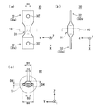
まず、図1~図4を参照しつつ、本発明の実施形態に係る電流検出装置1の構成について説明する。なお、図2(a)は平面図、図2(b)は側面図、図2(c)は正面図である。電流検出装置1は、電気自動車又はハイブリッド自動車などにおいて、バッテリとモータなどの機器とを電気的に接続するバスバーに流れる電流を検出する装置である。図1に示されるように、電流検出装置1は、磁性体コア10、ホール素子20、電流検出用バスバー30、絶縁筐体40及び電子基板50を備える。
First, the configuration of the current detection device 1 according to the embodiment of the present invention will be described with reference to FIGS. 2A is a plan view, FIG. 2B is a side view, and FIG. 2C is a front view. The current detection device 1 is a device that detects a current flowing in a bus bar that electrically connects a battery and a device such as a motor in an electric vehicle or a hybrid vehicle. As shown in FIG. 1, the current detection device 1 includes a magnetic core 10, a Hall element 20, a current detection bus bar 30, an insulating housing 40, and an electronic substrate 50.
<磁性体コア>
磁性体コア10は、パーマロイ、フェライト又はケイ素鋼などの磁性材料からなる粉体の焼結により成形された部材(磁性体)である。即ち、磁性体コア10は、磁性材料からなる固体粉末の集合体が、型枠内で圧縮され、さらに、その磁性体材料の融点よりも低い温度で加熱されることによって固化及び成形された部材である。
<Magnetic core>
The magnetic core 10 is a member (magnetic body) formed by sintering powder made of a magnetic material such as permalloy, ferrite, or silicon steel. That is, the magnetic core 10 is a member that is solidified and molded by compressing a solid powder aggregate made of a magnetic material in a mold and further heating it at a temperature lower than the melting point of the magnetic material. It is.
また、磁性体コア10は、両端が数ミリメートル程度のギャップ部12を介して対向し、中空部11の周囲を囲んで一連に形成された形状を有している。即ち、磁性体コア10は、狭いギャップ部12を有するものの概ね環状に形成されている。本実施形態における磁性体コア10は、円形状の中空部11を囲む円環状に形成されている。
Further, the magnetic core 10 has a shape in which both ends face each other via a gap portion 12 of about several millimeters and are formed in series around the periphery of the hollow portion 11. In other words, the magnetic core 10 has a narrow gap portion 12 but is formed in a generally annular shape. The magnetic core 10 in this embodiment is formed in an annular shape surrounding the circular hollow portion 11.
<ホール素子(磁電変換素子)>
ホール素子20は、磁性体コア10のギャップ部12に配置され、磁性体コア10の中空部11を通過する電流に応じて変化する磁束を検出し、磁束の検出信号を電気信号として出力する磁電変換素子の一例である。
<Hall element (magnetoelectric conversion element)>
The Hall element 20 is disposed in the gap portion 12 of the magnetic core 10, detects a magnetic flux that changes according to a current passing through the hollow portion 11 of the magnetic core 10, and outputs a magnetic flux detection signal as an electric signal. It is an example of a conversion element.
<電子基板>
電子基板50は、ホール素子20の端子21に接続される回路と、その回路と外部の他の回路とを接続するコネクタ51とが実装された基板である。従って、コネクタ51は、ホール素子20に対して電気的に接続されている。電子基板50に実装された回路は、例えば、ホール素子20から出力される磁束の検出信号を増幅する回路などである。ホール素子20は、コネクタ51を含む電子基板50を介して、外部の回路と接続される。
<Electronic board>
The electronic board 50 is a board on which a circuit connected to the terminal 21 of the Hall element 20 and a connector 51 for connecting the circuit and other external circuits are mounted. Accordingly, the connector 51 is electrically connected to the hall element 20. The circuit mounted on the electronic substrate 50 is, for example, a circuit that amplifies a magnetic flux detection signal output from the Hall element 20. The hall element 20 is connected to an external circuit through an electronic substrate 50 including a connector 51.
<電流検出用バスバー>
電流検出用バスバー30は、銅などの金属からなる導電体であり、バッテリと電装機器とを電気的に接続するバスバーの一部である。即ち、電流検出用バスバー30には、検出対象の電流が流れる。また、電流検出用バスバー30は、バッテリに対して予め接続されたバッテリ側のバスバーと、電装機器に対して予め接続された機器側のバスバーとは独立した部材である。そして、電流検出用バスバー30は、その両端が予め敷設された前段及び後段の他のバスバー(バッテリ側のバスバー及び機器側のバスバー)に対して連結される。電流検出用バスバー30と、これに連結された前段及び後段の他のバスバーとは、バッテリから電装機器へ至る電流伝送経路を形成する。なお、他のバスバーの端部は、電流伝送経路における電流検出用バスバー30の前段及び後段の導体の接続端の一例である。
<Bus bar for current detection>
The current detection bus bar 30 is a conductor made of a metal such as copper, and is a part of the bus bar that electrically connects the battery and the electrical equipment. That is, a current to be detected flows through the current detection bus bar 30. The current detection bus bar 30 is a member independent of the battery-side bus bar connected in advance to the battery and the device-side bus bar connected in advance to the electrical equipment. The current detection bus bar 30 is connected to the other bus bars (battery side bus bar and device side bus bar) of the front stage and the rear stage where both ends thereof are laid in advance. The current detection bus bar 30 and the other bus bars at the front stage and the rear stage connected thereto form a current transmission path from the battery to the electrical equipment. The end portions of the other bus bars are an example of connection ends of conductors at the front and rear stages of the current detection bus bar 30 in the current transmission path.
図1に示されるように、電流検出用バスバー30は、磁性体コア10の中空部11を貫通する棒状の導体の両端部分に加工が施された部材からなる。電流検出用バスバー30において、加工された両端部分は、電流伝送経路の前段及び後段各々の接続端と連結される端子部32である。即ち、電流検出用バスバー30は、概ね、中央部分において一定の範囲を占める棒状の貫通部31と、その貫通部31に対し中空部11を貫通する方向の両側各々に連なって形成された端子部32とを有する導体からなる部材である。
As shown in FIG. 1, the current detection bus bar 30 is made of a member in which both end portions of a rod-shaped conductor that penetrates the hollow portion 11 of the magnetic core 10 are processed. In the current detection bus bar 30, the processed both end portions are terminal portions 32 connected to the connection ends of the front and rear stages of the current transmission path. That is, the current detection bus bar 30 is generally formed of a rod-shaped through portion 31 that occupies a certain range in the central portion, and a terminal portion formed on both sides of the through portion 31 in the direction of passing through the hollow portion 11. 32, a member made of a conductor.
貫通部31は、磁性体コア10の中空部11を電流通過方向に沿って貫通する部分である。電流通過方向は、磁性体コア10の厚み方向であり、環状の磁性体コア10を筒とみなした場合におけるその筒の軸心方向であり、さらに、環状の磁性体コア10が形成する面に直交する方向でもある。各図において、電流通過方向は、X軸方向として記されている。以下の説明において、電流通過方向(X軸方向)を第1方向と称する。
The penetrating part 31 is a part that penetrates the hollow part 11 of the magnetic core 10 along the current passing direction. The current passing direction is the thickness direction of the magnetic core 10, the axial direction of the cylinder when the annular magnetic core 10 is regarded as a cylinder, and further on the surface formed by the annular magnetic core 10. It is also an orthogonal direction. In each figure, the current passing direction is indicated as the X-axis direction. In the following description, the current passing direction (X-axis direction) is referred to as a first direction.
本実施形態における端子部32は、平板状の端子部32aである。また、電流検出用バスバー30における貫通部31は、例えば、円柱状又は楕円柱状などの棒状に形成されている。各図において、平板状の端子部32aの幅方向及び厚み方向は、それぞれY軸方向及びZ軸方向として記されている。以下の説明において、平板状の端子部32aの幅方向(Y軸方向)及び厚み方向(Z軸方向)をそれぞれ第2方向及び第3方向と称する。
The terminal part 32 in the present embodiment is a flat terminal part 32a. Moreover, the penetration part 31 in the bus bar 30 for electric current detection is formed in rod shapes, such as column shape or elliptical column shape, for example. In each figure, the width direction and the thickness direction of the flat terminal portion 32a are described as a Y-axis direction and a Z-axis direction, respectively. In the following description, the width direction (Y-axis direction) and the thickness direction (Z-axis direction) of the flat terminal portion 32a are referred to as a second direction and a third direction, respectively.
図3は、電流検出用バスバー30の製造工程を模式的に示す斜視図である。電流検出用バスバー30は、棒状の金属部材30Xの両端部分に加工が施された構造を有する。棒状の金属部材30Xの断面の輪郭の最小幅は、磁性体コア10の両端の間隔であるギャップ高さD2よりも大きく形成されている。図3に示される金属部材30Xは円柱状であるため、金属部材30Xの断面の輪郭の最小幅は、金属部材30Xの直径である。
FIG. 3 is a perspective view schematically showing a manufacturing process of the current detection bus bar 30. The current detection bus bar 30 has a structure in which both end portions of a rod-shaped metal member 30X are processed. The minimum width of the cross-sectional contour of the rod-shaped metal member 30 </ b> X is formed to be larger than the gap height D <b> 2 that is the distance between both ends of the magnetic core 10. Since the metal member 30X shown in FIG. 3 has a cylindrical shape, the minimum width of the cross-sectional contour of the metal member 30X is the diameter of the metal member 30X.
より具体的には、電流検出用バスバー30は、磁性体コア10の中空部11を貫通する棒状の金属部材30Xの両端における一定範囲の部分が、プレス機60などを用いたプレス加工によって平板状に押しつぶされた構造を有する部材である。その際、棒状の金属部材30Xの両端のうちの少なくとも一方は、磁性体コア10の中空部11に棒状の金属部材30Xが挿通された後に、平板状にプレス加工される。
More specifically, the current detecting bus bar 30 has a plate-like portion formed by pressing using a press machine 60 or the like in a certain range at both ends of the rod-shaped metal member 30X that penetrates the hollow portion 11 of the magnetic core 10. It is the member which has the structure crushed by. At this time, at least one of both ends of the rod-shaped metal member 30X is pressed into a flat plate shape after the rod-shaped metal member 30X is inserted into the hollow portion 11 of the magnetic core 10.
即ち、電流検出装置1を製造する工程において、電流検出用バスバー30を製造する工程は、例えば、以下の手順で実行される。[1]まず、棒状の金属部材30Xを磁性体コア10の中空部11に貫通させる貫通工程が実行される。[2]次に、棒状の金属部材30Xの一方の端部を、プレス機60などによって他の部分よりも広い幅の平板状に押しつぶす第1のプレス工程が実行される。[3]最後に、棒状の金属部材30Xの他方の端部を、プレス機60などによって他の部分よりも広い幅の平板状に押しつぶす第2のプレス工程が実行される。
That is, in the process of manufacturing the current detection device 1, the process of manufacturing the current detection bus bar 30 is executed by the following procedure, for example. [1] First, a penetrating step for penetrating the rod-shaped metal member 30X through the hollow portion 11 of the magnetic core 10 is executed. [2] Next, a first pressing step is performed in which one end of the rod-shaped metal member 30X is crushed into a flat plate having a width wider than that of the other portion by the press machine 60 or the like. [3] Finally, a second pressing step is performed in which the other end of the rod-shaped metal member 30X is crushed into a flat plate having a width wider than that of the other portion by the press machine 60 or the like.
上記の製造工程において、[1]貫通工程は、[2]第1のプレス工程及び[3]第2のプレス工程のうちの一方又は両方が行われる前に実行されればよい。例えば、まず、[1]貫通工程が行われ、次に、[2]第1のプレス工程及び[3]第2のプレス工程が同時に行われてもよい。その他、まず、[2]第1のプレス工程が行われ、次に、[1]貫通工程が行われ、最後に[3]第2のプレス工程が行われてもよい。
[1] In the above manufacturing process, the [1] penetration process may be executed before one or both of [2] the first press process and [3] the second press process are performed. For example, first, [1] the penetration process may be performed, and then [2] the first pressing process and [3] the second pressing process may be performed simultaneously. In addition, [2] the first pressing process may be performed first, then [1] the penetration process may be performed, and finally [3] the second pressing process may be performed.
そして、平板状に押しつぶされた両端の部分が、電流検出用バスバー30における平板状の端子部32aを構成し、それらの間の棒状の部分が、電流検出用バスバー30の貫通部31を構成する。
Then, the portions of both ends crushed into a flat plate form a flat terminal portion 32 a in the current detection bus bar 30, and a bar-shaped portion between them forms a through portion 31 of the current detection bus bar 30. .
図3に示される金属部材30Xは円柱状の部材であり、このような金属部材30Xの両端の加工により製造される電流検出用バスバー30の貫通部31は円柱状である。なお、棒状の金属部材30Xは、断面が楕円の楕円棒状又は断面が矩形の角棒状であることも考えられる。また、棒状の金属部材30Xは、断面が四角形以外の多角形である棒状であることも考えられる。
The metal member 30X shown in FIG. 3 is a cylindrical member, and the through portion 31 of the current detection bus bar 30 manufactured by processing both ends of the metal member 30X is cylindrical. In addition, it is also conceivable that the rod-shaped metal member 30X has an elliptical bar shape with an elliptical cross section or a square bar shape with a rectangular cross section. Further, the rod-shaped metal member 30X may have a rod shape whose cross section is a polygon other than a quadrangle.
金属部材30Xの断面形状、即ち、貫通部31の断面形状は、磁性体コア10の中空部11の輪郭形状と相似な形状であることが望ましい。例えば、Nが3以上の整数であるとすると、磁性体コア10の中空部11の輪郭形状が正N角形である場合、金属部材30Xの形状が正N角柱であれば好適である。また、磁性体コア10の中空部11の輪郭形状が円形である場合、金属部材30Xの形状が円柱であれば好適である。また、磁性体コア10の中空部11の輪郭形状が、長軸と短軸との比がRである楕円形である場合、金属部材30Xの形状が、断面における長軸と短軸との比がRである楕円柱であれば好適である。
It is desirable that the cross-sectional shape of the metal member 30 </ b> X, that is, the cross-sectional shape of the penetrating portion 31 is similar to the contour shape of the hollow portion 11 of the magnetic core 10. For example, when N is an integer of 3 or more, when the contour shape of the hollow portion 11 of the magnetic core 10 is a regular N square, it is preferable that the shape of the metal member 30X is a regular N prism. Moreover, when the outline shape of the hollow part 11 of the magnetic body core 10 is circular, if the shape of the metal member 30X is a cylinder, it is suitable. Moreover, when the outline shape of the hollow part 11 of the magnetic body core 10 is an ellipse whose ratio of the major axis to the minor axis is R, the shape of the metal member 30X is the ratio of the major axis to the minor axis in the cross section. It is suitable if is an elliptic cylinder with R.
電流検出用バスバー30において、平板状の端子部32aの幅D5は、中空部11の直径D1(最大幅)よりも大きく形成されている。また、貫通部31の断面の輪郭の最小幅D4は、平板状の端子部32aの厚みD6よりも大きく形成されている。即ち、貫通部31の断面の輪郭の縦寸法と横寸法の比は、平板状の端子部32の断面の縦寸法と横寸法の比よりも1に近い。なお、貫通部31が円柱状である場合、貫通部31の断面の輪郭における最小幅D4と最大幅D3とは同じである。また、比が1に近いということは、比が1であることを含む。
In the current detection bus bar 30, the width D5 of the flat terminal portion 32a is larger than the diameter D1 (maximum width) of the hollow portion 11. Moreover, the minimum width D4 of the outline of the cross section of the penetration part 31 is formed larger than the thickness D6 of the flat terminal part 32a. In other words, the ratio of the vertical dimension and the horizontal dimension of the cross-sectional outline of the penetrating portion 31 is closer to 1 than the ratio of the vertical dimension and the horizontal dimension of the cross-section of the flat terminal portion 32. In addition, when the penetration part 31 is cylindrical, the minimum width D4 and the maximum width D3 in the outline of the cross section of the penetration part 31 are the same. Moreover, that the ratio is close to 1 includes that the ratio is 1.
また、電流検出用バスバー30において、貫通部31の断面の輪郭の最小幅D4は、磁性体コア10の両端の間隔であるギャップ高さD2よりも大きく形成されている。しかも、前述したように、平板状の端子部32aの幅D5は、磁性体コア10の中空部11の直径D1(最大幅)よりも大きい。そのため、予め製造された電流検出用バスバー30の貫通部31に対して磁性体コア10を装着することはできない。従って、磁性体コア10と、その磁性体コア10の中空部11に貫通した状態の電流検出用バスバー30とのセットが作られた後に、電流検出用バスバー30が前段及び後段の他のバスバーに接続される。
Further, in the current detection bus bar 30, the minimum width D4 of the contour of the cross section of the through portion 31 is formed to be larger than the gap height D2 that is the distance between both ends of the magnetic core 10. Moreover, as described above, the width D5 of the flat terminal portion 32a is larger than the diameter D1 (maximum width) of the hollow portion 11 of the magnetic core 10. Therefore, the magnetic core 10 cannot be mounted on the through-hole 31 of the current detection bus bar 30 manufactured in advance. Accordingly, after a set of the magnetic core 10 and the current detection bus bar 30 penetrating through the hollow portion 11 of the magnetic core 10 is made, the current detection bus bar 30 is connected to the other bus bars in the front and rear stages. Connected.
そこで、平板状の端子部32aには、ネジ止め用の貫通孔32Zが形成されており、これにより、平板状の端子部32aは、ネジにより前段及び後段の他のバスバーと連結される。図5は、電流検出装置1における平板状の端子部32aが、予め敷設された前段及び後段の他のバスバー9に対し、ネジ8によって連結される様子を模式的に示す斜視図である。
Therefore, a through hole 32Z for screwing is formed in the flat terminal portion 32a, whereby the flat terminal portion 32a is connected to the other bus bars in the front and rear stages by screws. FIG. 5 is a perspective view schematically showing a state in which the flat terminal portion 32a in the current detection device 1 is connected to the other bus bars 9 in the front stage and the rear stage that are laid in advance by screws 8.
なお、図5において、便宜上、絶縁筐体40の記載は省略されている。図5に示されるように、他のバスバー9における、平板状の端子部32aと連結される接続端は、例えば、端子台としての構造を備え、ネジ止め用の孔9Aが形成されている。なお、電流検出用バスバー30における端子部32は、ネジ止め用の貫通孔32Zが形成された平板状の端子部32aの他、他のバスバー9との嵌め合い機構などの他の構造を有することも考えられる。
In FIG. 5, the description of the insulating housing 40 is omitted for convenience. As shown in FIG. 5, the connection end of the other bus bar 9 connected to the flat terminal portion 32a has a structure as a terminal block, for example, and is formed with a screw hole 9A. The terminal portion 32 of the current detection bus bar 30 has other structures such as a fitting mechanism with another bus bar 9 in addition to the flat terminal portion 32a in which the through hole 32Z for screwing is formed. Is also possible.
<絶縁筐体>
絶縁筐体40は、絶縁体からなり、磁性体コア10とホール素子20と電流検出用バスバー30と電子基板50とを保持する部材であり、本体ケース41及び本体ケース41に取り付けられる蓋部材42とを含む。本体ケース41及び蓋部材42の各々は、例えば、ポリアミド(PA)、ポリプロピレン(PP)、ポリブチレンテレフタレート(PBT)又はABS樹脂などの絶縁性の樹脂からなる一体成形部材である。
<Insulated housing>
The insulating housing 40 is made of an insulator, and is a member that holds the magnetic core 10, the Hall element 20, the current detection bus bar 30, and the electronic substrate 50. Including. Each of the main body case 41 and the lid member 42 is an integrally formed member made of an insulating resin such as polyamide (PA), polypropylene (PP), polybutylene terephthalate (PBT), or ABS resin.
本体ケース41は、開口部を有する箱状に形成され、蓋部材42は、本体ケース41に取り付けられることによって本体ケース41の開口部を塞ぐ。本体ケース41には、その内側の面において突出する第1保持部43及び第2保持部44が形成されている。そして、本体ケース41は、第1保持部43及び第2保持部44により、磁性体コア10と、中空部11を貫通する電流検出用バスバー30と、ギャップ部12に配置されたホール素子20とを、それらが相互に接触しない状態で保持する。
The main body case 41 is formed in a box shape having an opening, and the lid member 42 is attached to the main body case 41 to close the opening of the main body case 41. The main body case 41 is formed with a first holding portion 43 and a second holding portion 44 that protrude on the inner surface thereof. The main body case 41 includes the first holding portion 43 and the second holding portion 44, the magnetic core 10, the current detection bus bar 30 penetrating the hollow portion 11, and the Hall element 20 disposed in the gap portion 12. Are held in a state where they are not in contact with each other.
より具体的には、第1保持部43は、磁性体コア10とその中空部11を貫通する電流検出用バスバー30の貫通部31との隙間に嵌り込むことにより、磁性体コア10と電流検出用バスバー30とを、それらが相互に接触しない状態で保持する。また、第2保持部44は、磁性体コア10とそのギャップ部12に配置されたホール素子20との隙間に嵌り込むことにより、磁性体コア10とホール素子20とを、それらが相互に接触しない状態で保持する。
More specifically, the first holding portion 43 is fitted into the gap between the magnetic core 10 and the through portion 31 of the current detection bus bar 30 that penetrates the hollow portion 11, thereby detecting the current detection of the magnetic core 10. The bus bars 30 are held in a state where they do not contact each other. Further, the second holding portion 44 fits into the gap between the magnetic core 10 and the Hall element 20 disposed in the gap portion 12, thereby bringing the magnetic core 10 and the Hall element 20 into contact with each other. Hold in a state that does not.
また、本体ケース41及び蓋部材42には、電流検出用バスバー30の両端の端子部32が内側から外側へ挿入されるスリット状の端子部通し孔45が形成されている。磁性体コア10の中空部11を貫通する電流検出用バスバー30における一方の端子部32が、本体ケース41の端子部通し孔45に通された状態において、本体ケース41の第1保持部43及び第2保持部44は、磁性体コア10、ホール素子20及び電流検出用バスバー30を保持する。
The main body case 41 and the lid member 42 are formed with slit-like terminal portion through holes 45 into which the terminal portions 32 at both ends of the current detection bus bar 30 are inserted from the inside to the outside. In a state where one terminal portion 32 of the current detection bus bar 30 penetrating through the hollow portion 11 of the magnetic core 10 is passed through the terminal portion through hole 45 of the main body case 41, the first holding portion 43 of the main body case 41 and The second holding unit 44 holds the magnetic core 10, the Hall element 20, and the current detection bus bar 30.
また、蓋部材42は、磁性体コア10、ホール素子20及び電流検出用バスバー30を保持する本体ケース41に対し、電子基板50を挟み込みつつ、本体ケース41の開口部を塞ぐように取り付けられる。その際、電流検出用バスバー30における他方の端子部32が、蓋部材42の端子部通し孔45に対して内側から外側へ通される。また、電子基板50が本体ケース41と蓋部材42との間に挟み込まれることにより、電子基板50に実装されたコネクタ51は、本体ケース41に形成された欠け部46に嵌り込んだ状態で保持される。
The lid member 42 is attached to the main body case 41 holding the magnetic core 10, the Hall element 20 and the current detection bus bar 30 so as to close the opening of the main body case 41 while sandwiching the electronic substrate 50. At this time, the other terminal portion 32 of the current detection bus bar 30 is passed from the inside to the outside with respect to the terminal portion through hole 45 of the lid member 42. Further, since the electronic board 50 is sandwiched between the main body case 41 and the lid member 42, the connector 51 mounted on the electronic board 50 is held in a state of being fitted into the chipped portion 46 formed in the main body case 41. Is done.
さらに、本体ケース41及び蓋部材42には、それらを組み合わせ状態で保持するロック機構47,48が設けられている。図1に示されるロック機構47,48は、本体ケース41の側面に突出して形成された爪部47と、蓋部材42の側方に形成された環状の枠部48とを備える。本体ケース41の爪部47が、蓋部材42の枠部48が形成する孔に嵌り込むことにより、本体ケース41及び蓋部材42は、それらが組み合わされた状態で保持される。
Furthermore, the main body case 41 and the lid member 42 are provided with lock mechanisms 47 and 48 for holding them in a combined state. The lock mechanisms 47 and 48 shown in FIG. 1 include a claw portion 47 formed to project from the side surface of the main body case 41 and an annular frame portion 48 formed on the side of the lid member 42. When the claw portion 47 of the main body case 41 is fitted into the hole formed by the frame portion 48 of the lid member 42, the main body case 41 and the lid member 42 are held in a state where they are combined.
図4は、本体ケース41及び蓋部材42が組み合わされた状態における電流検出装置1の平面図である。図4に示されるように、本体ケース41及び蓋部材42(絶縁筐体40)は、電流検出用バスバー30の端子部32における貫通孔32Zが形成された部分(端子部)と、電子基板50のコネクタ51とが外部に露出する状態で、磁性体コア10と電流検出用バスバー30の貫通部31とホール素子20とを覆いつつ保持する。
FIG. 4 is a plan view of the current detection device 1 in a state where the main body case 41 and the lid member 42 are combined. As shown in FIG. 4, the main body case 41 and the lid member 42 (insulating housing 40) include a portion (terminal portion) in which the through hole 32 </ b> Z is formed in the terminal portion 32 of the current detection bus bar 30, and the electronic substrate 50. With the connector 51 exposed to the outside, the magnetic core 10, the through-hole 31 of the current detection bus bar 30, and the Hall element 20 are covered and held.
<効果>
以上に示した電流検出装置1の電流検出用バスバー30において、貫通部31は、断面の輪郭の最大幅D3が端子部の幅D5(最大幅)よりも小さく形成されている。即ち、貫通部31の断面の輪郭形状は、端子部32に対し、第2方向においてくびれた形状を有している。その結果、電流検出装置1においては、前段及び後段の他のバスバーの幅との関係において比較的小さな磁性体コア10を採用することができ、磁性体コア10を含む装置全体を小型化できる。
<Effect>
In the current detection bus bar 30 of the current detection device 1 described above, the through portion 31 is formed so that the maximum width D3 of the cross-sectional contour is smaller than the width D5 (maximum width) of the terminal portion. That is, the outline shape of the cross section of the through portion 31 is constricted in the second direction with respect to the terminal portion 32. As a result, in the current detection device 1, the relatively small magnetic core 10 can be employed in relation to the widths of the other bus bars in the front and rear stages, and the entire apparatus including the magnetic core 10 can be downsized.
また、電流検出用バスバー30において、磁性体コア10の中空部11を貫通する貫通部31は、丸棒もしくは角棒など、平板状以外の形状で形成されている。そのため、その貫通部31は、平板状のバスバーに比べ、その最大幅が磁性体コア10の中空部11の直径D1(幅)よりも小さいという制約の中で、より大きな断面積で形成されることができる。従って、比較的小さな磁性体コア10が採用された場合でも、電流検出用バスバー30の過剰な発熱を防止できる。
Further, in the current detection bus bar 30, the penetrating portion 31 penetrating the hollow portion 11 of the magnetic core 10 is formed in a shape other than a flat shape such as a round bar or a square bar. Therefore, the through-hole 31 is formed with a larger cross-sectional area under the constraint that the maximum width thereof is smaller than the diameter D1 (width) of the hollow portion 11 of the magnetic core 10 compared to the flat bus bar. be able to. Therefore, even when a relatively small magnetic core 10 is employed, excessive heat generation of the current detection bus bar 30 can be prevented.
また、電流検出用バスバー30の貫通部31の断面形状が、磁性体コア10の中空部11の輪郭形状と相似な形状であれば、貫通部31と磁性体コア10との隙間をより小さくすることができる。その結果、より小さな磁性体コア10を採用することによる装置の小型化が可能となる。
Moreover, if the cross-sectional shape of the penetration part 31 of the current detection bus bar 30 is similar to the outline shape of the hollow part 11 of the magnetic core 10, the gap between the penetration part 31 and the magnetic core 10 is further reduced. be able to. As a result, the apparatus can be reduced in size by adopting a smaller magnetic core 10.
さらに、電流検出用バスバー30において、貫通部31の断面形状は、最小幅D4が端子部32の厚みD6(最小幅)よりも大きく形成されている。そして、棒状の金属部材30Xの両端が平板状に押しつぶされた構造を有する電流検出用バスバー30においては、貫通部31における導体の断面積は、端子部32における導体の断面積以上である。従って、貫通部31における過剰な発熱を防止できる。なお、端子部32は、それに圧接される連結用のネジ8及び他のバスバー9と併せた全体の熱容量が大きくなる部分であるため、孔32Yの存在による発熱の問題は生じない。
Further, in the current detection bus bar 30, the cross-sectional shape of the through portion 31 is formed such that the minimum width D4 is larger than the thickness D6 (minimum width) of the terminal portion 32. In the current detection bus bar 30 having a structure in which both ends of the rod-shaped metal member 30 </ b> X are flattened, the cross-sectional area of the conductor in the through portion 31 is greater than or equal to the cross-sectional area of the conductor in the terminal portion 32. Therefore, excessive heat generation in the penetration part 31 can be prevented. In addition, since the terminal part 32 is a part in which the overall heat capacity combined with the connecting screw 8 and the other bus bar 9 pressed against each other is increased, the problem of heat generation due to the presence of the hole 32Y does not occur.
また、棒状の金属部材30Xの両端部分が平板状に押しつぶされた構造を有する電流検出用バスバー30においては、棒状の金属部材30Xを磁性体コア10の中空部11に挿入した後に、中空部11の幅D1よりも広い幅の平板状の端子部32を作ることができる。即ち、貫通部31を磁性体コア10のギャップ部12に通過させることは必要とされない。従って、棒状の貫通部31の断面の幅D3(直径)が、磁性体コア10におけるギャップ高さD2よりも大きく形成された電流検出用バスバー30を容易に作製することができる。
Further, in the current detecting bus bar 30 having a structure in which both end portions of the rod-shaped metal member 30X are crushed into a flat plate shape, the hollow portion 11 is inserted after the rod-shaped metal member 30X is inserted into the hollow portion 11 of the magnetic core 10. The flat terminal portion 32 having a width wider than the width D1 can be formed. That is, it is not necessary to pass the through portion 31 through the gap portion 12 of the magnetic core 10. Therefore, the current detection bus bar 30 in which the cross-sectional width D3 (diameter) of the bar-shaped through portion 31 is larger than the gap height D2 in the magnetic core 10 can be easily manufactured.
なお、電流の検出感度を高めるためには、ギャップ高さD2を小さくし、ギャップ部12に配置されたホール素子20と磁性体コア10の両端との隙間を小さくすることが望ましい。
In order to increase the current detection sensitivity, it is desirable to reduce the gap height D2 and reduce the gap between the Hall element 20 disposed in the gap portion 12 and both ends of the magnetic core 10.
また、電流検出装置1においては、磁性体コア10とホール素子20と電流検出用バスバー30とが、露出されるべき部分である端子部32の貫通孔32Zの部分(端子部)及びコネクタ51以外を覆う絶縁筐体40によって所定の位置関係に保持される。これにより、予め敷設されたバスバー9に対して電流検出装置1を取り付ける作業が容易となる。
In the current detection device 1, the magnetic core 10, the Hall element 20, and the current detection bus bar 30 are other than the portion (terminal portion) of the through hole 32 </ b> Z of the terminal portion 32 and the connector 51 that should be exposed. Is held in a predetermined positional relationship by an insulating housing 40 covering the. Thereby, the operation | work which attaches the electric current detection apparatus 1 with respect to the bus bar 9 laid beforehand becomes easy.
また、電流検出装置1において、磁性体コア10は、磁性材料からなる粉体の焼結により成形された部材である。焼結タイプの磁性体コア10は、積層タイプの磁性体コアとは異なり、小型化された場合でも寸法誤差が生じにくい。そのため、電流検出装置1は、磁性体コア10の寸法誤差に起因する電流の検出誤差が生じにくい。さらに、焼結タイプの磁性体コア10は、積層タイプの磁性体コアに比べ、製造の工数及びコストを低減できる点においても優れている。
In the current detection device 1, the magnetic core 10 is a member formed by sintering powder made of a magnetic material. Unlike the laminated type magnetic core, the sintered type magnetic core 10 is less likely to cause a dimensional error even if it is downsized. Therefore, the current detection device 1 is less likely to cause a current detection error due to the dimensional error of the magnetic core 10. Further, the sintered type magnetic core 10 is superior in that the number of manufacturing steps and cost can be reduced as compared with the laminated type magnetic core.
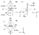
<電流検出用バスバー(第1応用例)>
次に、図6及び図7を参照しつつ、電流検出装置1に採用可能な第1応用例に係る電流検出用バスバー30Aについて説明する。図6は、電流検出用バスバー30Aの三面図である。また、図7は、電流検出用バスバー30Aの元となる平板状の金属部材30Yの平面図である。なお、図6において、電流検出用バスバー30Aと組み合わされる磁性体コア10が、仮想線(二点鎖線)により示されている。また、図6(a)は平面図、図6(b)は側面図、図6(c)は正面図である。
<Current detection bus bar (first applied example)>
Next, a current detection bus bar 30A according to a first application example that can be employed in the current detection device 1 will be described with reference to FIGS. 6 and 7. FIG. 6 is a three-side view of the current detection bus bar 30A. FIG. 7 is a plan view of a flat metal member 30Y that is a source of the current detection bus bar 30A. In FIG. 6, the magnetic core 10 combined with the current detection bus bar 30 </ b> A is indicated by a virtual line (two-dot chain line). 6A is a plan view, FIG. 6B is a side view, and FIG. 6C is a front view.
図6及び図7において、図1~図5に示される構成要素と同じ構成要素は、同じ参照符号が付されている。以下、電流検出用バスバー30Aにおける電流検出用バスバー30と異なる点についてのみ説明する。
6 and 7, the same components as those shown in FIGS. 1 to 5 are given the same reference numerals. Hereinafter, only the difference between the current detection bus bar 30A and the current detection bus bar 30 will be described.
電流検出用バスバー30Aも、電流検出用バスバー30と同様に、磁性体コア10の中空部11を第1方向(X軸方向)に沿って貫通する貫通部31Aと、その貫通部31Aに対し第1方向の両側各々に連なる平板状の端子部32aとが形成された導体からなる部材である。
Similarly to the current detection bus bar 30, the current detection bus bar 30 </ b> A penetrates the hollow portion 11 of the magnetic core 10 along the first direction (X-axis direction), and the current detection bus bar 30 </ b> A is It is a member made of a conductor in which flat terminal portions 32a connected to both sides in one direction are formed.
電流検出用バスバー30Aにおいても、端子部32aの幅D5は、中空部11の直径D1(最大幅)よりも大きく形成されている。また、貫通部31Aの断面の輪郭の最小幅D4は、端子部32aの厚みD6よりも大きく形成されている。
Also in the current detection bus bar 30 </ b> A, the width D <b> 5 of the terminal portion 32 a is formed larger than the diameter D <b> 1 (maximum width) of the hollow portion 11. Moreover, the minimum width D4 of the outline of the cross section of the penetration part 31A is formed larger than the thickness D6 of the terminal part 32a.
一方、電流検出用バスバー30Aにおいて、貫通部31Aの断面の輪郭の最小幅D4は、磁性体コア10の両端の間隔であるギャップ高さD2よりも小さく形成されている。そのため、予め製造された電流検出用バスバー30Aの貫通部31Aに対して磁性体コア10をそのギャップ部12を通じて装着することが可能である。
On the other hand, in the current detection bus bar 30A, the minimum width D4 of the contour of the cross section of the through portion 31A is formed smaller than the gap height D2 that is the distance between both ends of the magnetic core 10. Therefore, the magnetic core 10 can be mounted through the gap portion 12 with respect to the through portion 31A of the current detection bus bar 30A manufactured in advance.
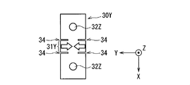
電流検出用バスバー30Aは、平板状の金属部材30Yにおける一部分31Yが、その一部分31Yの第1方向(X軸方向)における両側に形成された切り込み34に沿って、第2方向(Y軸方向)における両側から折り返された構造を有する部材である。
In the current detection bus bar 30A, the portion 31Y of the flat metal member 30Y is in the second direction (Y-axis direction) along the cuts 34 formed on both sides in the first direction (X-axis direction) of the portion 31Y. This is a member having a structure folded from both sides.
金属部材30Yにおける切り込み34は、一部分31Yの第1方向(X軸方向)における両側において、第2方向(Y軸方向)の両端から内側へ向けて形成されている。そして、折り返された一部分31Yが、電流検出用バスバー30Aの貫通部31Aを構成し、折り返された一部分31Yの両側の部分が端子部32aを構成する。このような電流検出用バスバー30Aの作製は容易である。
The notches 34 in the metal member 30Y are formed from both ends in the second direction (Y-axis direction) to the inside on both sides in the first direction (X-axis direction) of the portion 31Y. The folded portion 31Y constitutes the through portion 31A of the current detecting bus bar 30A, and the portions on both sides of the folded portion 31Y constitute the terminal portion 32a. Such a current detection bus bar 30A can be easily manufactured.
電流検出用バスバー30Aにおいても、貫通部31Aの断面の輪郭形状は、端子部32aに対し、第2方向(Y軸方向)においてくびれた形状を有している。その結果、電流検出装置1において、電流検出用バスバー30Aが採用された場合でも、バスバーの幅との関係において比較的小さな磁性体コア10を採用することができ、磁性体コア10を含む装置全体の大型化を回避できる。
Also in the current detection bus bar 30A, the outline shape of the cross section of the through portion 31A is constricted in the second direction (Y-axis direction) with respect to the terminal portion 32a. As a result, even when the current detection bus bar 30 </ b> A is employed in the current detection device 1, the relatively small magnetic core 10 can be employed in relation to the width of the bus bar, and the entire device including the magnetic core 10. Can be avoided.
さらに、電流検出用バスバー30Aにおいて、貫通部31Aの断面の輪郭形状は、最小幅D4が端子部32aの厚みD6(最小幅)よりも大きく形成されている。これにより、貫通部31Aにおける導体の断面積は、端子部32aにおける導体の断面積と比較して大幅に小さくならない。特に、平板状の金属部材30Yの一部が折り返された構造を有する電流検出用バスバー30Aにおいては、貫通部31Aにおける導体の断面積と、端子部32aにおける導体の断面積とは同じである。
Further, in the current detection bus bar 30A, the cross-sectional contour shape of the through portion 31A is formed such that the minimum width D4 is larger than the thickness D6 (minimum width) of the terminal portion 32a. Thereby, the cross-sectional area of the conductor in the penetration part 31A is not significantly reduced as compared with the cross-sectional area of the conductor in the terminal part 32a. In particular, in the current detection bus bar 30A having a structure in which a part of the flat metal member 30Y is folded, the cross-sectional area of the conductor in the through portion 31A and the cross-sectional area of the conductor in the terminal portion 32a are the same.
但し、電流検出用バスバー30Aにおいては、貫通部31Aと端子部32aとの間における切り込み34が形成された部分については、導体の断面積がその前後の部分の導体の断面積よりも小さくなる。しかしながら、実験の結果、切り込み34の幅がごく狭い幅である場合、切り込み34が形成された部分におけるインピーダンスの増大は、電流検出用バスバー30A全体としてはほとんど無視できる程度に小さいことがわかっている。そのため、電流検出用バスバー30Aにおいて、幅のごく狭い切り込み34が形成されている場合、貫通部31における過剰な発熱を防止できる。
However, in the current detection bus bar 30A, the cross-sectional area of the conductor is smaller than the cross-sectional area of the conductors in the front and rear portions of the portion where the notch 34 is formed between the through portion 31A and the terminal portion 32a. However, as a result of experiments, it has been found that when the width of the notch 34 is very narrow, the increase in impedance in the portion where the notch 34 is formed is small enough to be ignored for the entire current detection bus bar 30A. . For this reason, in the current detection bus bar 30 </ b> A, when the narrow cut 34 is formed, excessive heat generation in the through portion 31 can be prevented.
<電流検出用バスバー(第2応用例)>
次に、図8~図10を参照しつつ、電流検出装置1に採用可能な第2応用例に係る電流検出用バスバー30Bについて説明する。図8は、電流検出用バスバー30Bの三面図である。また、図9は、電流検出用バスバー30Bの元となる平板状の金属部材30Zの平面図である。また、図10は、電流検出用バスバー30Bが磁性体コア10の中空部11に挿入される様子を示す図である。なお、図8において、電流検出用バスバー30Bと組み合わされる磁性体コア10が、仮想線(二点鎖線)により示されている。また、図8(a)は平面図、図8(b)は側面図、図8(c)は正面図である。
<Bus bar for current detection (second application example)>
Next, a current detection bus bar 30B according to a second application example that can be employed in the current detection device 1 will be described with reference to FIGS. FIG. 8 is a three-side view of the current detection bus bar 30B. FIG. 9 is a plan view of a flat metal member 30Z that is the base of the current detection bus bar 30B. FIG. 10 is a diagram illustrating a state in which the current detection bus bar 30 </ b> B is inserted into the hollow portion 11 of the magnetic core 10. In FIG. 8, the magnetic core 10 combined with the current detection bus bar 30B is indicated by a virtual line (two-dot chain line). 8A is a plan view, FIG. 8B is a side view, and FIG. 8C is a front view.
図8~図10において、図1~図5に示される構成要素と同じ構成要素は、同じ参照符号が付されている。以下、電流検出用バスバー30Bにおける電流検出用バスバー30と異なる点についてのみ説明する。
8 to 10, the same components as those shown in FIGS. 1 to 5 are given the same reference numerals. Hereinafter, only the difference between the current detection bus bar 30B and the current detection bus bar 30 will be described.
電流検出用バスバー30Bも、電流検出用バスバー30と同様に、磁性体コア10の中空部11を第1方向(X軸方向)に沿って貫通する貫通部31Bと、その貫通部31Bに対し第1方向の両側各々に連なる平板状の端子部32aとが形成された導体からなる部材である。
Similarly to the current detection bus bar 30, the current detection bus bar 30 </ b> B has a through portion 31 </ b> B that penetrates the hollow portion 11 of the magnetic core 10 along the first direction (X-axis direction), and the second through the through portion 31 </ b> B. It is a member made of a conductor in which flat terminal portions 32a connected to both sides in one direction are formed.
電流検出用バスバー30Bにおいても、端子部32aの幅D5は、中空部11の直径D1(最大幅)よりも大きく形成されている。また、貫通部31Bの断面の輪郭の最小幅D4は、端子部32aの厚みD6よりも大きく形成されている。
Also in the current detection bus bar 30B, the width D5 of the terminal portion 32a is formed larger than the diameter D1 (maximum width) of the hollow portion 11. Moreover, the minimum width D4 of the outline of the cross section of the penetration part 31B is formed larger than the thickness D6 of the terminal part 32a.
電流検出用バスバー30Bは、平板状の金属部材30Zにおける一部分31Zが、その一部分31Zの第1方向(X軸方向)における両側に形成された切り込み34に沿って、第2方向(Y軸方向)における片側から折り返された構造を有する部材である。金属部材30Zにおける切り込み34は、一部分31Zの第1方向(X軸方向)における両側において、第2方向(Y軸方向)の一方の端から内側へ向けて形成されている。そして、折り返された一部分31Zが、電流検出用バスバー30Bの貫通部31Bを構成し、折り返された一部分31Zの両側の部分が端子部32aを構成する。このような電流検出用バスバー30Bの作製も容易である。
In the current detection bus bar 30B, the portion 31Z of the flat metal member 30Z has a second direction (Y-axis direction) along cuts 34 formed on both sides in the first direction (X-axis direction) of the portion 31Z. This is a member having a structure folded from one side. The notches 34 in the metal member 30Z are formed inward from one end in the second direction (Y-axis direction) on both sides of the portion 31Z in the first direction (X-axis direction). The folded portion 31Z constitutes the through portion 31B of the current detection bus bar 30B, and the portions on both sides of the folded portion 31Z constitute the terminal portion 32a. Such a current detection bus bar 30B can be easily manufactured.
また、電流検出用バスバー30Bにおいて、貫通部31Bの断面の輪郭の最小幅D4は、磁性体コア10の両端の間隔であるギャップ高さD2よりも大きく形成されている。さらに、電流検出用バスバー30Bにおいて、折り返された部分31Zである貫通部31Bは、第2方向(Y軸方向)における一方の端の側へ偏った位置に形成されている。図8~図10に示される例では、貫通部31Bは、Y軸の正方向の端へ偏った位置に形成されている。
Further, in the current detection bus bar 30B, the minimum width D4 of the cross-sectional contour of the through portion 31B is formed to be larger than the gap height D2 that is the distance between both ends of the magnetic core 10. Further, in the current detection bus bar 30B, the through portion 31B which is the folded portion 31Z is formed at a position biased toward one end in the second direction (Y-axis direction). In the example shown in FIGS. 8 to 10, the penetrating portion 31B is formed at a position deviated toward the positive end of the Y axis.
以上に示した構造を有する電流検出用バスバー30Bは、貫通部31Bの断面の輪郭の最小幅D4が磁性体コア10のギャップ高さD2よりも大きく形成されている場合であっても、貫通部31Bを磁性体コア10の中空部11に挿入することが可能となる。
Even if the current detection bus bar 30B having the above-described structure is formed so that the minimum width D4 of the contour of the cross section of the through portion 31B is larger than the gap height D2 of the magnetic core 10, the through portion 31B can be inserted into the hollow portion 11 of the magnetic core 10.
即ち、図10に示されるように、第1方向(X軸方向)から見た場合に、貫通部31B全体が中空部11と重なって位置し、かつ、端子部32aが中空部11及びギャップ部12の両方に重なるとともに磁性体コア10と重ならないように位置するように、電流検出用バスバー30B及び磁性体コア10を配置する。その状態で、電流検出用バスバー30B又は磁性体コア10が第1方向(X軸方向)に移動されることにより、貫通部31Bを磁性体コア10の中空部11に挿入することができる。そのため、予め製造された電流検出用バスバー30Bの貫通部31Bに対して磁性体コア10を装着することが可能である。
That is, as shown in FIG. 10, when viewed from the first direction (X-axis direction), the entire through portion 31B is positioned so as to overlap the hollow portion 11, and the terminal portion 32a is formed between the hollow portion 11 and the gap portion. The current detection bus bar 30 </ b> B and the magnetic core 10 are arranged so as to overlap both of the magnetic cores 10 and not to overlap the magnetic cores 10. In this state, the current detecting bus bar 30 </ b> B or the magnetic core 10 is moved in the first direction (X-axis direction), so that the penetrating portion 31 </ b> B can be inserted into the hollow portion 11 of the magnetic core 10. Therefore, it is possible to attach the magnetic core 10 to the through-hole 31B of the current detection bus bar 30B manufactured in advance.
<電流検出用バスバー(第3応用例)>
次に、図11を参照しつつ、電流検出装置1に採用可能な第3応用例に係る電流検出用バスバー30Cについて説明する。図11は、電流検出用バスバー30C及び磁性体コア10の斜視図である。図11において、図1~図5に示される構成要素と同じ構成要素は、同じ参照符号が付されている。以下、電流検出用バスバー30Cにおける電流検出用バスバー30と異なる点についてのみ説明する。
<Current detection bus bar (third applied example)>
Next, a current detection bus bar 30C according to a third application example that can be employed in the current detection device 1 will be described with reference to FIG. FIG. 11 is a perspective view of the current detection bus bar 30 </ b> C and the magnetic core 10. In FIG. 11, the same components as those shown in FIGS. 1 to 5 are given the same reference numerals. Hereinafter, only the differences between the current detection bus bar 30C and the current detection bus bar 30 will be described.
電流検出用バスバー30Cも、電流検出用バスバー30と同様に、磁性体コア10の中空部11を第1方向(X軸方向)に沿って貫通する貫通部31と、その貫通部31に対し第1方向の両側各々に連なる平板状の端子部32aが形成されている。
Similarly to the current detection bus bar 30, the current detection bus bar 30 </ b> C has a through portion 31 that penetrates the hollow portion 11 of the magnetic core 10 along the first direction (X-axis direction), and the second through the through portion 31. Flat terminal portions 32a are formed on both sides in one direction.
但し、電流検出用バスバー30Cにおける平板状の2つの端子部32aは、それぞれ非平行な面に沿って形成されている。図11に示される例では、平板状の2つの端子部32aのうちの一方は、X-Y平面に沿って形成され、他方は、X-Z平面に沿って形成されている。電流検出装置1において、図11に示されるような電流検出用バスバー30Cが、電流検出用バスバー30の代わりに採用されてもよい。
However, the two flat terminal portions 32a in the current detection bus bar 30C are formed along non-parallel surfaces. In the example shown in FIG. 11, one of the two plate-like terminal portions 32a is formed along the XY plane, and the other is formed along the XZ plane. In the current detection device 1, a current detection bus bar 30 </ b> C as shown in FIG. 11 may be employed instead of the current detection bus bar 30.
図11に示される電流検出用バスバー30Cの採用は、前段及び後段のバスバー各々が形成する面の角度が異なる場合に好適である。なお、平板状の2つの端子部32aは、図11に示されるように相互に90°で交差する2つの平面各々に沿って形成される他、他の角度で交差する2つの平面各々に沿って形成されることも考えられる。
The adoption of the current detection bus bar 30C shown in FIG. 11 is suitable when the angles of the surfaces formed by the front and rear bus bars are different. The two flat terminal portions 32a are formed along two planes intersecting each other at 90 ° as shown in FIG. 11, and along each of two planes intersecting at other angles. It is also possible that it is formed.
<電流検出用バスバー(第4応用例)>
次に、図12を参照しつつ、電流検出装置1に採用可能な第4応用例に係る電流検出用バスバー30Dについて説明する。図12は、電流検出用バスバー30D及び磁性体コア10の斜視図である。図12において、図1~図5に示される構成要素と同じ構成要素は、同じ参照符号が付されている。以下、電流検出用バスバー30Dにおける電流検出用バスバー30と異なる点についてのみ説明する。
<Current detection bus bar (fourth application example)>
Next, a current detection bus bar 30D according to a fourth application example that can be employed in the current detection device 1 will be described with reference to FIG. FIG. 12 is a perspective view of the current detection bus bar 30 </ b> D and the magnetic core 10. In FIG. 12, the same components as those shown in FIGS. 1 to 5 are given the same reference numerals. Hereinafter, only differences between the current detection bus bar 30D and the current detection bus bar 30 will be described.
電流検出用バスバー30Dは、電流検出用バスバー30,30Aと比較して、両端部における端子部32の形状が異なる。電流検出用バスバー30Dにおける端子部32は、棒状の金属部材30Xの端部における、据え込み加工により他の部分よりも太く加工された部分である。以下、このように加工された端子部32を、大径の端子部32bと称する。さらに、この大径の端子部32bには、前段及び後段の他のバスバーの接続端と連結するためのネジ8が締め込まれるねじ孔32Yが形成されている。
The current detection bus bar 30D is different from the current detection bus bars 30 and 30A in the shape of the terminal portions 32 at both ends. The terminal portion 32 in the current detection bus bar 30D is a portion that is processed to be thicker than the other portions by the upsetting process at the end of the rod-shaped metal member 30X. Hereinafter, the terminal portion 32 processed in this way is referred to as a large-diameter terminal portion 32b. Further, the large-diameter terminal portion 32b is formed with a screw hole 32Y into which a screw 8 for coupling with a connection end of another bus bar at the front stage and the rear stage is fastened.
図13は、電流検出用バスバー30Dの製造工程を模式的に示す斜視図である。電流検出用バスバー30Dも、電流検出用バスバー30と同様に、棒状の金属部材30Xの両端部分に加工が施された構造を有する。棒状の金属部材30Xの断面の輪郭の最小幅は、磁性体コア10の両端の間隔であるギャップ高さD2よりも大きく形成されている。
FIG. 13 is a perspective view schematically showing a manufacturing process of the current detection bus bar 30D. Similarly to the current detection bus bar 30, the current detection bus bar 30 </ b> D has a structure in which both end portions of the rod-shaped metal member 30 </ b> X are processed. The minimum width of the cross-sectional contour of the rod-shaped metal member 30 </ b> X is formed to be larger than the gap height D <b> 2 that is the distance between both ends of the magnetic core 10.
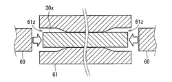
より具体的には、電流検出用バスバー30Dにおける大径の端子部32bは、磁性体コア10の中空部11を貫通する棒状の金属部材30Xの端部が、大径の端子部32bを形作る型枠部61zが形成された治具61及びプレス機60などを用いた据え込み加工によって成形された部分である。
More specifically, the large-diameter terminal portion 32b in the current detection bus bar 30D is a mold in which the end portion of the rod-shaped metal member 30X that penetrates the hollow portion 11 of the magnetic core 10 forms the large-diameter terminal portion 32b. This is a portion formed by upsetting using a jig 61 in which the frame portion 61z is formed, a press machine 60, and the like.
治具61は、棒状の金属部材30Xにおける端部以外の部分を元々の形状に沿って保持する。また、治具61の型枠部61zは、棒状の金属部材30Xの端部の周囲を間隔を隔てて取り囲む。そして、治具61に保持された棒状の金属部材30Xの端部は、プレス機60などにより、棒状の金属部材30Xの軸方向に沿って加圧される。これにより、棒状の金属部材30Xの端部は、他の部分よりも太く加工される。その際、棒状の金属部材30Xの両端のうちの少なくとも一方は、磁性体コア10の中空部11に棒状の金属部材30Xが挿通された後に、据え込み加工が施される。
The jig 61 holds portions other than the end portions of the rod-shaped metal member 30X along the original shape. Moreover, the mold part 61z of the jig 61 surrounds the periphery of the end part of the rod-shaped metal member 30X with an interval. And the edge part of the rod-shaped metal member 30X hold | maintained at the jig | tool 61 is pressurized along the axial direction of the rod-shaped metal member 30X with the press machine 60 grade | etc.,. Thereby, the edge part of the rod-shaped metal member 30X is processed thicker than another part. At that time, at least one of both ends of the rod-shaped metal member 30 </ b> X is subjected to upsetting after the rod-shaped metal member 30 </ b> X is inserted into the hollow portion 11 of the magnetic core 10.
即ち、電流検出装置1を製造する工程において、電流検出用バスバー30を製造する工程は、例えば、以下の手順で実行される。[1]まず、棒状の金属部材30Xを磁性体コア10の中空部11に貫通させる貫通工程が実行される。[2]次に、棒状の金属部材30Xの一方の端部について、プレス機60及び治具61などによって他の部分よりも太く加工する第1の据え込み加工の工程が実行される。[3]最後に、棒状の金属部材30Xの他方の端部について、プレス機60及び治具61などによって他の部分よりも太く加工する第2の据え込み加工の工程が実行される。
That is, in the process of manufacturing the current detection device 1, the process of manufacturing the current detection bus bar 30 is executed by the following procedure, for example. [1] First, a penetrating step for penetrating the rod-shaped metal member 30X through the hollow portion 11 of the magnetic core 10 is executed. [2] Next, a first upsetting process is performed in which one end of the rod-shaped metal member 30X is processed to be thicker than the other part by the press machine 60, the jig 61, and the like. [3] Finally, a second upsetting process is performed in which the other end of the rod-shaped metal member 30X is processed to be thicker than the other parts by the press machine 60, the jig 61, and the like.
上記の製造工程において、[1]貫通工程は、[2]第1の据え込み加工の工程及び[3]第2の据え込み加工の工程のうちの一方又は両方が行われる前に実行されればよい。例えば、まず、[1]貫通工程が行われ、次に、[2]第1の据え込み加工の工程及び[3]第2の据え込み加工の工程が同時に行われてもよい。その他、まず、[2]第1の据え込み加工の工程が行われ、次に、[1]貫通工程が行われ、最後に[3]第2の据え込み加工の工程が行われてもよい。
In the above manufacturing process, the [1] penetration process is performed before one or both of the [2] first upsetting process and the [3] second upsetting process are performed. That's fine. For example, first, [1] the penetration process may be performed, and then [2] the first upsetting process and [3] the second upsetting process may be performed simultaneously. In addition, first, [2] the first upsetting process may be performed, then [1] the penetration process may be performed, and finally [3] the second upsetting process may be performed. .
そして、他の部分よりも太く加工された両端の部分が、電流検出用バスバー30Dにおける大径の端子部32bを構成し、それらの間の棒状の部分が、電流検出用バスバー30Dの貫通部31を構成する。
Then, both end portions processed to be thicker than other portions constitute a large-diameter terminal portion 32b in the current detection bus bar 30D, and a rod-shaped portion between them forms the through portion 31 of the current detection bus bar 30D. Configure.
図12に示される電流検出用バスバー30Dの元となる金属部材30Xは円柱状の部材であり、このような金属部材30Xの両端の加工により製造される電流検出用バスバー30Dの貫通部31は円柱状である。なお、電流検出用バスバー30Dの元となる棒状の金属部材30Xも、電流検出用バスバー30,30Aの場合と同様に、断面が楕円の楕円棒状又は断面が多角形である棒状であることも考えられる。電流検出用バスバー30Dにおいても、その元となる金属部材30Xの断面形状、即ち、貫通部31の断面形状は、磁性体コア10の中空部11の輪郭形状と相似な形状であることが望ましい。
The metal member 30X that is the base of the current detection bus bar 30D shown in FIG. 12 is a cylindrical member, and the through-hole 31 of the current detection bus bar 30D manufactured by processing both ends of the metal member 30X is a circle. It is columnar. It should be noted that the rod-shaped metal member 30X that is the base of the current detection bus bar 30D may also be an elliptical bar having an elliptical cross section or a bar having a polygonal cross section, as in the case of the current detection bus bars 30 and 30A. It is done. Also in the current detection bus bar 30 </ b> D, it is desirable that the cross-sectional shape of the metal member 30 </ b> X as a base, that is, the cross-sectional shape of the through portion 31 is similar to the contour shape of the hollow portion 11 of the magnetic core 10.
また、図12に示される大径の端子部32bの最大幅D5は、貫通部31の最大幅D3及び中空部11の直径D1(最大幅)よりも大きく形成されている。これにより、貫通部31の太さ、即ち、元の棒状の金属部材30Xの太さが、ねじ孔32Yを形成するために十分な太さでなくてもよい。電流検出装置1において、図12に示されるような電流検出用バスバー30Dが、電流検出用バスバー30の代わりに採用されてもよい。
Further, the maximum width D5 of the large-diameter terminal portion 32b shown in FIG. 12 is formed larger than the maximum width D3 of the through portion 31 and the diameter D1 (maximum width) of the hollow portion 11. Thereby, the thickness of the penetration part 31, ie, the thickness of the original rod-shaped metal member 30X, does not have to be sufficient to form the screw hole 32Y. In the current detection device 1, a current detection bus bar 30 </ b> D as shown in FIG. 12 may be employed instead of the current detection bus bar 30.
<電流検出用バスバー(第5応用例)>
次に、図14を参照しつつ、電流検出装置1に採用可能な第5応用例に係る電流検出用バスバー30Eについて説明する。図14は、電流検出用バスバー30E及び磁性体コア10の斜視図である。図14において、図1~図12に示される構成要素と同じ構成要素は、同じ参照符号が付されている。以下、電流検出用バスバー30Eにおける電流検出用バスバー30Dと異なる点についてのみ説明する。
<Bus bar for current detection (fifth application example)>
Next, a current detection bus bar 30E according to a fifth application example that can be employed in the current detection device 1 will be described with reference to FIG. FIG. 14 is a perspective view of the current detection bus bar 30 </ b> E and the magnetic core 10. In FIG. 14, the same components as those shown in FIGS. 1 to 12 are given the same reference numerals. Hereinafter, only the difference between the current detection bus bar 30E and the current detection bus bar 30D will be described.
電流検出用バスバー30Eも、電流検出用バスバー30Dと同様に、磁性体コア10の中空部11を第1方向(X軸方向)に沿って貫通する貫通部31と、その貫通部31に対し第1方向の両側各々に連なる大径の端子部32bが形成されている。
Similarly to the current detection bus bar 30 </ b> D, the current detection bus bar 30 </ b> E has a through portion 31 that penetrates the hollow portion 11 of the magnetic core 10 along the first direction (X-axis direction), and the second through the through portion 31. Large-diameter terminal portions 32b are formed on both sides in one direction.
但し、電流検出用バスバー30Eは、貫通部31から大径の端子部32bに至る途中の部分に曲げ部33が形成されている。図14に示される電流検出用バスバー30Eは、貫通部31から大径の端子部32bに至る途中の部分において90°曲がる曲げ部33が形成されている。電流検出装置1において、図14に示されるような電流検出用バスバー30Eが、電流検出用バスバー30の代わりに採用されてもよい。
However, the current detection bus bar 30E has a bent portion 33 formed in the middle of the through portion 31 and the large-diameter terminal portion 32b. The current detection bus bar 30E shown in FIG. 14 is formed with a bent portion 33 that bends by 90 ° in the middle portion from the penetrating portion 31 to the large-diameter terminal portion 32b. In the current detection device 1, a current detection bus bar 30 </ b> E as shown in FIG. 14 may be employed instead of the current detection bus bar 30.
図14に示される電流検出用バスバー30Eの採用は、前段及び後段のバスバー各々が形成する面の角度が異なる場合に好適である。なお、曲げ部33の曲げ角度は、図14に示されるように90°である他、他の曲げ角度であることも考えられる。電流検出装置1において、図14に示されるような電流検出用バスバー30Eが、電流検出用バスバー30の代わりに採用されてもよい。また、電流検出用バスバー30,30Aが、電流検出用バスバー30Eと同様の曲げ部33を有することも考えられる。
The adoption of the current detection bus bar 30E shown in FIG. 14 is suitable when the angles of the surfaces formed by the front and rear bus bars are different. In addition, the bending angle of the bending part 33 is also considered to be other bending angles besides 90 degrees as FIG. 14 shows. In the current detection device 1, a current detection bus bar 30 </ b> E as shown in FIG. 14 may be employed instead of the current detection bus bar 30. It is also conceivable that the current detection bus bars 30 and 30A have the same bent portion 33 as the current detection bus bar 30E.
なお、以上に示した電流検出用バスバー30A,30B,30C,30D,30Eは、電流検出用バスバー30と同様に、磁性体コア10及びホール素子20とともに、絶縁筐体40により、相互に接触しない状態で保持される。但し、電流検出用バスバー30B,30C,30D,30Eが採用される場合、電流検出用バスバー30が採用される場合と比較して、絶縁筐体40の端子部通し孔45の位置又は形状が異なる。
Note that the current detection bus bars 30A, 30B, 30C, 30D, and 30E described above do not come into contact with each other by the insulating housing 40 together with the magnetic core 10 and the hall element 20, similarly to the current detection bus bar 30. Held in a state. However, when the current detection bus bars 30B, 30C, 30D, and 30E are employed, the position or shape of the terminal portion through hole 45 of the insulating housing 40 is different from that when the current detection bus bar 30 is employed. .
<電流検出用バスバー(第6応用例)>
次に、図15を参照しつつ、電流検出装置1に採用可能な第6応用例に係る電流検出用バスバーについて説明する。図15は、第6応用例に係る電流検出用バスバー30の製造工程を模式的に示す斜視図である。図15において、図1~図3に示される構成要素と同じ構成要素は、同じ参照符号が付されている。以下、第6応用例に係る電流検出用バスバーにおける電流検出用バスバー30と異なる点についてのみ説明する。
<Bus bar for current detection (sixth application example)>
Next, a current detection bus bar according to a sixth application example that can be employed in the current detection device 1 will be described with reference to FIG. FIG. 15 is a perspective view schematically showing a manufacturing process of the current detection bus bar 30 according to the sixth application example. In FIG. 15, the same components as those shown in FIGS. 1 to 3 are given the same reference numerals. Hereinafter, only differences from the current detection bus bar 30 in the current detection bus bar according to the sixth application example will be described.
第6応用例に係る電流検出用バスバーは、筒状の金属部材30Vの両端部分に加工が施された構造を有し、電流検出用バスバー30と同様の外形を有する。筒状の金属部材30Vの断面の輪郭の最小幅は、磁性体コア10の両端の間隔であるギャップ高さD2よりも大きく形成されている。図15に示される金属部材30Vは円筒状であるため、金属部材30Vの断面の輪郭の最小幅は、金属部材30Vの直径である。
The current detection bus bar according to the sixth application example has a structure in which both end portions of the cylindrical metal member 30V are processed, and has the same outer shape as the current detection bus bar 30. The minimum width of the contour of the cross section of the cylindrical metal member 30 </ b> V is formed to be larger than the gap height D <b> 2 that is the distance between both ends of the magnetic core 10. Since the metal member 30V shown in FIG. 15 is cylindrical, the minimum width of the cross-sectional contour of the metal member 30V is the diameter of the metal member 30V.
より具体的には、第6応用例に係る電流検出用バスバーは、磁性体コア10の中空部11を貫通する筒状の金属部材30Vの両端における一定範囲の部分が、プレス機60などを用いたプレス加工によって平板状に押しつぶされた構造を有する部材である。その際、筒状の金属部材30Vの両端のうちの少なくとも一方は、磁性体コア10の中空部11に筒状の金属部材30Vが挿通された後に、平板状にプレス加工される。
More specifically, in the current detection bus bar according to the sixth application example, a portion of a certain range at both ends of the cylindrical metal member 30V that penetrates the hollow portion 11 of the magnetic core 10 uses the press machine 60 or the like. It is a member having a structure crushed into a flat plate shape by press working. At that time, at least one of both ends of the cylindrical metal member 30 </ b> V is pressed into a flat plate shape after the cylindrical metal member 30 </ b> V is inserted into the hollow portion 11 of the magnetic core 10.
そして、平板状に押しつぶされた両端の部分が、第6応用例に係る電流検出用バスバーにおける平板状の端子部32aを構成し、それらの間の筒状の部分が、第6応用例に係る電流検出用バスバーの貫通部31を構成する。
And the part of the both ends crushed flat form the flat terminal part 32a in the bus bar for electric current detection which concerns on a 6th application example, The cylindrical part between them concerns on a 6th application example. A through portion 31 of the current detection bus bar is formed.
なお、第6応用例に係る電流検出用バスバーは、電流検出用バスバー30と同様に、磁性体コア10及びホール素子20とともに、絶縁筐体40により、相互に接触しない状態で保持される。
Note that the current detection bus bar according to the sixth application example is held in a state of not being in contact with each other by the insulating housing 40 together with the magnetic core 10 and the hall element 20, similarly to the current detection bus bar 30.
図15に示される金属部材30Vは円筒状の部材であり、このような金属部材30Vの両端の加工により製造される電流検出用バスバーの貫通部31は円筒状である。なお、筒状の金属部材30Vは、断面が楕円の楕円筒状又は断面が矩形の角筒状であることも考えられる。また、筒状の金属部材30Vは、断面が四角形以外の多角形である筒状であることも考えられる。
The metal member 30V shown in FIG. 15 is a cylindrical member, and the through-hole 31 of the current detection bus bar manufactured by processing both ends of the metal member 30V is cylindrical. Note that the cylindrical metal member 30V may be an elliptic cylinder having an elliptical cross section or a square cylinder having a rectangular cross section. Moreover, it is also conceivable that the cylindrical metal member 30V has a cylindrical shape whose cross section is a polygon other than a quadrangle.
金属部材30Vの断面形状、即ち、第6応用例に係る電流検出用バスバーにおける貫通部31の断面形状は、磁性体コア10の中空部11の輪郭形状と相似な形状であることが望ましい。電流検出装置1において、図14に示されるような電流検出用バスバー30Eが、電流検出用バスバー30の代わりに採用された場合も、電流検出用バスバー30が採用された場合と同様の効果が得られる。
It is desirable that the cross-sectional shape of the metal member 30V, that is, the cross-sectional shape of the through portion 31 in the current detection bus bar according to the sixth application example is similar to the contour shape of the hollow portion 11 of the magnetic core 10. In the current detection device 1, when the current detection bus bar 30E as shown in FIG. 14 is employed instead of the current detection bus bar 30, the same effect as that when the current detection bus bar 30 is employed is obtained. It is done.
<その他>
電流検出装置1の電流検出用バスバーにおいて、図1又は図11に示される平板状の端子部32aが一方の端子部32として採用され、図12又は図14に示される大径の端子部32bが他方の端子部32として採用されることも考えられる。
<Others>
In the current detection bus bar of the current detection device 1, the flat terminal portion 32a shown in FIG. 1 or 11 is adopted as one terminal portion 32, and the large-diameter terminal portion 32b shown in FIG. 12 or FIG. It is conceivable that the other terminal portion 32 is adopted.