WO2012157331A1 - Battery pack structure for electric vehicles - Google Patents
Battery pack structure for electric vehicles Download PDFInfo
- Publication number
- WO2012157331A1 WO2012157331A1 PCT/JP2012/057179 JP2012057179W WO2012157331A1 WO 2012157331 A1 WO2012157331 A1 WO 2012157331A1 JP 2012057179 W JP2012057179 W JP 2012057179W WO 2012157331 A1 WO2012157331 A1 WO 2012157331A1
- Authority
- WO
- WIPO (PCT)
- Prior art keywords
- battery
- battery pack
- harness
- temperature
- passage
- Prior art date
Links
Images


Classifications
-
- H—ELECTRICITY
- H01—ELECTRIC ELEMENTS
- H01M—PROCESSES OR MEANS, e.g. BATTERIES, FOR THE DIRECT CONVERSION OF CHEMICAL ENERGY INTO ELECTRICAL ENERGY
- H01M10/00—Secondary cells; Manufacture thereof
- H01M10/60—Heating or cooling; Temperature control
- H01M10/61—Types of temperature control
- H01M10/613—Cooling or keeping cold
-
- B—PERFORMING OPERATIONS; TRANSPORTING
- B60—VEHICLES IN GENERAL
- B60K—ARRANGEMENT OR MOUNTING OF PROPULSION UNITS OR OF TRANSMISSIONS IN VEHICLES; ARRANGEMENT OR MOUNTING OF PLURAL DIVERSE PRIME-MOVERS IN VEHICLES; AUXILIARY DRIVES FOR VEHICLES; INSTRUMENTATION OR DASHBOARDS FOR VEHICLES; ARRANGEMENTS IN CONNECTION WITH COOLING, AIR INTAKE, GAS EXHAUST OR FUEL SUPPLY OF PROPULSION UNITS IN VEHICLES
- B60K1/00—Arrangement or mounting of electrical propulsion units
- B60K1/04—Arrangement or mounting of electrical propulsion units of the electric storage means for propulsion
-
- B—PERFORMING OPERATIONS; TRANSPORTING
- B60—VEHICLES IN GENERAL
- B60K—ARRANGEMENT OR MOUNTING OF PROPULSION UNITS OR OF TRANSMISSIONS IN VEHICLES; ARRANGEMENT OR MOUNTING OF PLURAL DIVERSE PRIME-MOVERS IN VEHICLES; AUXILIARY DRIVES FOR VEHICLES; INSTRUMENTATION OR DASHBOARDS FOR VEHICLES; ARRANGEMENTS IN CONNECTION WITH COOLING, AIR INTAKE, GAS EXHAUST OR FUEL SUPPLY OF PROPULSION UNITS IN VEHICLES
- B60K11/00—Arrangement in connection with cooling of propulsion units
- B60K11/06—Arrangement in connection with cooling of propulsion units with air cooling
-
- B—PERFORMING OPERATIONS; TRANSPORTING
- B60—VEHICLES IN GENERAL
- B60L—PROPULSION OF ELECTRICALLY-PROPELLED VEHICLES; SUPPLYING ELECTRIC POWER FOR AUXILIARY EQUIPMENT OF ELECTRICALLY-PROPELLED VEHICLES; ELECTRODYNAMIC BRAKE SYSTEMS FOR VEHICLES IN GENERAL; MAGNETIC SUSPENSION OR LEVITATION FOR VEHICLES; MONITORING OPERATING VARIABLES OF ELECTRICALLY-PROPELLED VEHICLES; ELECTRIC SAFETY DEVICES FOR ELECTRICALLY-PROPELLED VEHICLES
- B60L50/00—Electric propulsion with power supplied within the vehicle
- B60L50/50—Electric propulsion with power supplied within the vehicle using propulsion power supplied by batteries or fuel cells
- B60L50/60—Electric propulsion with power supplied within the vehicle using propulsion power supplied by batteries or fuel cells using power supplied by batteries
- B60L50/64—Constructional details of batteries specially adapted for electric vehicles
-
- H—ELECTRICITY
- H01—ELECTRIC ELEMENTS
- H01M—PROCESSES OR MEANS, e.g. BATTERIES, FOR THE DIRECT CONVERSION OF CHEMICAL ENERGY INTO ELECTRICAL ENERGY
- H01M10/00—Secondary cells; Manufacture thereof
- H01M10/60—Heating or cooling; Temperature control
- H01M10/62—Heating or cooling; Temperature control specially adapted for specific applications
- H01M10/625—Vehicles
-
- H—ELECTRICITY
- H01—ELECTRIC ELEMENTS
- H01M—PROCESSES OR MEANS, e.g. BATTERIES, FOR THE DIRECT CONVERSION OF CHEMICAL ENERGY INTO ELECTRICAL ENERGY
- H01M10/00—Secondary cells; Manufacture thereof
- H01M10/60—Heating or cooling; Temperature control
- H01M10/65—Means for temperature control structurally associated with the cells
- H01M10/656—Means for temperature control structurally associated with the cells characterised by the type of heat-exchange fluid
- H01M10/6561—Gases
- H01M10/6562—Gases with free flow by convection only
-
- H—ELECTRICITY
- H01—ELECTRIC ELEMENTS
- H01M—PROCESSES OR MEANS, e.g. BATTERIES, FOR THE DIRECT CONVERSION OF CHEMICAL ENERGY INTO ELECTRICAL ENERGY
- H01M50/00—Constructional details or processes of manufacture of the non-active parts of electrochemical cells other than fuel cells, e.g. hybrid cells
- H01M50/20—Mountings; Secondary casings or frames; Racks, modules or packs; Suspension devices; Shock absorbers; Transport or carrying devices; Holders
- H01M50/204—Racks, modules or packs for multiple batteries or multiple cells
- H01M50/207—Racks, modules or packs for multiple batteries or multiple cells characterised by their shape
- H01M50/209—Racks, modules or packs for multiple batteries or multiple cells characterised by their shape adapted for prismatic or rectangular cells
-
- H—ELECTRICITY
- H01—ELECTRIC ELEMENTS
- H01M—PROCESSES OR MEANS, e.g. BATTERIES, FOR THE DIRECT CONVERSION OF CHEMICAL ENERGY INTO ELECTRICAL ENERGY
- H01M50/00—Constructional details or processes of manufacture of the non-active parts of electrochemical cells other than fuel cells, e.g. hybrid cells
- H01M50/20—Mountings; Secondary casings or frames; Racks, modules or packs; Suspension devices; Shock absorbers; Transport or carrying devices; Holders
- H01M50/249—Mountings; Secondary casings or frames; Racks, modules or packs; Suspension devices; Shock absorbers; Transport or carrying devices; Holders specially adapted for aircraft or vehicles, e.g. cars or trains
-
- B—PERFORMING OPERATIONS; TRANSPORTING
- B60—VEHICLES IN GENERAL
- B60K—ARRANGEMENT OR MOUNTING OF PROPULSION UNITS OR OF TRANSMISSIONS IN VEHICLES; ARRANGEMENT OR MOUNTING OF PLURAL DIVERSE PRIME-MOVERS IN VEHICLES; AUXILIARY DRIVES FOR VEHICLES; INSTRUMENTATION OR DASHBOARDS FOR VEHICLES; ARRANGEMENTS IN CONNECTION WITH COOLING, AIR INTAKE, GAS EXHAUST OR FUEL SUPPLY OF PROPULSION UNITS IN VEHICLES
- B60K1/00—Arrangement or mounting of electrical propulsion units
- B60K2001/003—Arrangement or mounting of electrical propulsion units with means for cooling the electrical propulsion units
- B60K2001/005—Arrangement or mounting of electrical propulsion units with means for cooling the electrical propulsion units the electric storage means
-
- B—PERFORMING OPERATIONS; TRANSPORTING
- B60—VEHICLES IN GENERAL
- B60K—ARRANGEMENT OR MOUNTING OF PROPULSION UNITS OR OF TRANSMISSIONS IN VEHICLES; ARRANGEMENT OR MOUNTING OF PLURAL DIVERSE PRIME-MOVERS IN VEHICLES; AUXILIARY DRIVES FOR VEHICLES; INSTRUMENTATION OR DASHBOARDS FOR VEHICLES; ARRANGEMENTS IN CONNECTION WITH COOLING, AIR INTAKE, GAS EXHAUST OR FUEL SUPPLY OF PROPULSION UNITS IN VEHICLES
- B60K1/00—Arrangement or mounting of electrical propulsion units
- B60K1/04—Arrangement or mounting of electrical propulsion units of the electric storage means for propulsion
- B60K2001/0405—Arrangement or mounting of electrical propulsion units of the electric storage means for propulsion characterised by their position
- B60K2001/0438—Arrangement under the floor
-
- H—ELECTRICITY
- H01—ELECTRIC ELEMENTS
- H01M—PROCESSES OR MEANS, e.g. BATTERIES, FOR THE DIRECT CONVERSION OF CHEMICAL ENERGY INTO ELECTRICAL ENERGY
- H01M2220/00—Batteries for particular applications
- H01M2220/20—Batteries in motive systems, e.g. vehicle, ship, plane
-
- H—ELECTRICITY
- H01—ELECTRIC ELEMENTS
- H01M—PROCESSES OR MEANS, e.g. BATTERIES, FOR THE DIRECT CONVERSION OF CHEMICAL ENERGY INTO ELECTRICAL ENERGY
- H01M50/00—Constructional details or processes of manufacture of the non-active parts of electrochemical cells other than fuel cells, e.g. hybrid cells
- H01M50/20—Mountings; Secondary casings or frames; Racks, modules or packs; Suspension devices; Shock absorbers; Transport or carrying devices; Holders
- H01M50/271—Lids or covers for the racks or secondary casings
-
- Y—GENERAL TAGGING OF NEW TECHNOLOGICAL DEVELOPMENTS; GENERAL TAGGING OF CROSS-SECTIONAL TECHNOLOGIES SPANNING OVER SEVERAL SECTIONS OF THE IPC; TECHNICAL SUBJECTS COVERED BY FORMER USPC CROSS-REFERENCE ART COLLECTIONS [XRACs] AND DIGESTS
- Y02—TECHNOLOGIES OR APPLICATIONS FOR MITIGATION OR ADAPTATION AGAINST CLIMATE CHANGE
- Y02E—REDUCTION OF GREENHOUSE GAS [GHG] EMISSIONS, RELATED TO ENERGY GENERATION, TRANSMISSION OR DISTRIBUTION
- Y02E60/00—Enabling technologies; Technologies with a potential or indirect contribution to GHG emissions mitigation
- Y02E60/10—Energy storage using batteries
Definitions
- the present invention relates to a battery pack structure for an electric vehicle in which a battery module, a junction box, and a battery controller are mounted in the internal space of the battery pack case.
- the battery pack of an electric vehicle includes a battery module that is an assembly of battery cells, a junction box that supplies / cuts off / distributes strong power using a relay circuit, a battery controller that performs battery management, and an internal space of the battery pack case, It is equipped with.
- a battery module that is an assembly of battery cells
- a junction box that supplies / cuts off / distributes strong power using a relay circuit
- a battery controller that performs battery management
- an internal space of the battery pack case It is equipped with.
- Patent Document 1 discloses a structure in which a battery module, a junction box, and a battery controller are connected to each other by a high-power harness that bundles strong wires or a weak-power harness that bundles weak wires.
- the internal space of the case is divided into three divided rectangular areas, and a battery module is mounted in each of the three divided rectangular areas.
- a T-shaped gap formed by the opposite side surfaces of the three battery modules is used as a mounting space for the junction box and a harness routing route.
- harness wiring workability is low and harness durability is lowered.
- the clearance secured when a plurality of battery modules are mounted in the internal space of the battery pack case is used as a temperature-controlled air passage for supplying temperature-controlled air for managing the battery temperature.
- the temperature adjustment air passage and the harness routing route the temperature adjustment air will bend in the gap where the temperature adjustment air flows.
- a harness is routed. As a result, there is a problem that the harness becomes passage resistance and a smooth flow of temperature-controlled air cannot be secured.
- An object of the present invention is to provide a battery pack structure for an electric vehicle.
- a battery pack structure for an electric vehicle is a junction box that supplies / cuts off / distributes high power by a battery module in a battery pack case and a relay circuit in an internal space of the battery pack case. And a battery controller that performs battery management.
- the gap that is secured when the battery module is mounted in the internal space of the battery pack case is defined as a temperature adjustment air passage through which the temperature adjustment air flows.
- the junction box and the battery controller are respectively arranged at positions separated from one of the temperature control air passages so as to face one straight passage portion.
- the harness which connects the said junction box and the said battery controller was routed along the said linear channel
- the junction box and the battery controller are respectively arranged at positions separated from one of the temperature-controlled air passages formed in the internal space of the battery pack case and facing the straight passage portion, and are routed along the straight passage portion. Connected by a harness. Therefore, when the junction box and the battery controller are connected to each other by a harness, a simplified harness routing operation is performed so as to be along one straight path portion. For this reason, compared with the harness wiring to the curved path
- FIG. 1 is a schematic side view showing a one-box type electric vehicle on which a battery pack BP employing the structure of Example 1 is mounted.
- 1 is a schematic bottom view showing a one-box type electric vehicle on which a battery pack BP employing the structure of Example 1 is mounted.
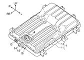
- 1 is an overall perspective view showing a battery pack BP of Example 1.
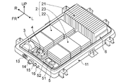
- FIG. 3 is a perspective view of the battery pack BP according to the first embodiment with a battery case upper cover removed.
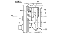
- FIG. 3 is a plan view of the battery pack BP according to the first embodiment with a battery case upper cover removed illustrating an internal configuration and a flow of temperature control air. It is the A section enlarged view of FIG.
- FIG. 3 is a plan view illustrating a region division configuration of a case internal space of the battery pack BP according to the first embodiment.
- FIG. 3 is a circuit diagram showing a bus bar connection configuration and a harness connection configuration of each pack component in the battery pack BP of the first embodiment.
- 3 is a plan view showing a bus bar connection configuration and a harness connection configuration of each pack component in a case internal space of the battery pack BP of Embodiment 1.
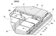
- FIG. FIG. 10 is a perspective view in the arrow B direction of FIG. 9 showing a harness connection configuration of each pack component in the case internal space of the battery pack BP of the first embodiment.
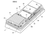
- FIG. 10 is a perspective view in the direction of arrow C in FIG. 9 showing the harness connection configuration of each pack component in the case internal space of the battery pack BP of the first embodiment.
- FIG. 3 is a perspective view illustrating an LB controller mounted on the battery pack BP according to the first embodiment.
- Example 1 shown in the drawings.
- the configuration of the battery pack structure of the electric vehicle according to the first embodiment is described as “in-vehicle configuration of battery pack BP”, “pack component of battery pack BP”, “region division configuration of case internal space of battery pack BP”, “ The description will be divided into “Bus bar connection configuration of battery high power circuit” and “Harness connection configuration between pack components”.
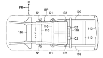
- FIGS. 1 and 2 are a schematic side view and a schematic bottom view showing a one-box type electric vehicle on which a battery pack BP employing the structure of the first embodiment is mounted.
- the in-vehicle configuration of the battery pack BP will be described with reference to FIGS. 1 and 2.
- the battery pack BP is disposed at the center of the wheel base at the lower part of the vehicle body floor 100 as shown in FIG.
- the vehicle body floor 100 is provided from the connection position between the motor chamber 101 and the dash panel 104 that defines the vehicle compartment 102 to the vehicle rear end position that secures the luggage compartment 103 communicating with the vehicle compartment 102, from the vehicle front to the vehicle rear.
- the vehicle compartment 102 includes an instrument panel 105, a center console box 106, an air conditioner unit 107, and an occupant seat 108.
- the battery pack BP is supported at eight points on a vehicle body member that is a vehicle body strength member.
- the vehicle body member includes a pair of side members 109, 109 extending in the vehicle front-rear direction and a plurality of cross members 110, 110,... Connecting the pair of side members 109, 109 in the vehicle width direction.
- Both sides of the battery pack BP are supported at six points by a pair of first side member support points S1, S1, a pair of first cross member support points C1, C1, and a pair of second side member support points S2, S2.
- the rear side of the battery pack BP is supported at two points by a pair of second cross member support points C2 and C2.
- the battery pack BP is connected to a high-power module 112 (DC / DC) disposed in the motor chamber 101 via a charge / discharge harness 111 that is arranged in a straight line in the vehicle longitudinal direction along the dash panel 104.
- DC converter + charger In addition to the high-power module 112, the motor chamber 101 includes an inverter 113 and a motor drive unit 114 (traveling motor + reduction gear + differential gear).
- a quick charging port 115 having a charging port lid and a normal charging port 116 are provided at the front position of the vehicle.
- the quick charge port 115 and the high voltage module 112 are connected by a quick charge harness 117.
- the normal charging port 116 and the high voltage module 112 are connected by a normal charging harness 118.
- the battery pack BP is connected to an air conditioning system including an air conditioner unit 107 disposed in the instrument panel 105. That is, the internal temperature of the battery pack BP on which a battery module, which will be described later, is mounted is managed by temperature control air (cold air, hot air). In addition, cold wind is produced by introducing a refrigerant into an evaporator through a branch refrigerant pipe from an air conditioning system. Hot air is generated by operating a PTC heater via a PTC harness from the air conditioning system.
- the battery pack BP is connected to an external electronic control system via a bidirectional communication line such as a CAN cable (not shown). That is, the battery pack BP performs discharge control (power running control), charge control (rapid charge control / normal charge control / regenerative control), and the like of the battery module through integrated control based on information exchange with an external electronic control system.
- a bidirectional communication line such as a CAN cable (not shown). That is, the battery pack BP performs discharge control (power running control), charge control (rapid charge control / normal charge control / regenerative control), and the like of the battery module through integrated control based on information exchange with an external electronic control system.
- FIGS. 3 to 6 are diagrams illustrating details of the battery pack BP of the first embodiment. Hereinafter, the pack components of the battery pack BP will be described with reference to FIGS.
- the battery pack BP of the first embodiment includes a battery pack case 1, a battery module 2, a temperature control unit 3, and a service disconnect switch 4 (hereinafter referred to as “SD switch”). ”), A junction box 5, and a lithium ion battery controller 6 (hereinafter referred to as“ LB controller ”).
- SD switch service disconnect switch 4
- LB controller lithium ion battery controller 6
- the battery pack case 1 is composed of two parts, a battery pack lower frame 11 and a battery pack upper cover 12, as shown in FIGS.
- the battery pack lower frame 11 is a frame member that is supported and fixed to the vehicle body member as shown in FIG.
- the battery pack lower frame 11 has a mounting space formed by a rectangular recess in which the battery module 2 and other pack components 3, 4, 5, and 6 are mounted.
- a refrigerant pipe connector terminal 13 At the frame front end edge of the battery pack lower frame 11, a refrigerant pipe connector terminal 13, a low-power connector terminal 16, a charge / discharge connector terminal 14, and a high-power connector terminal 15 for supplying high power for vehicle interior air conditioning are attached.
- the battery pack upper cover 12 is a cover member that is bolted to the outer peripheral portion of the battery pack lower frame 11 as shown in FIG.
- the battery pack upper cover 12 has an uneven step surface shape corresponding to the uneven height shape of the battery module 2 among the pack components 2, 3, 4, 5, 6 mounted on the battery pack lower frame 11. With a cover surface.
- the battery module 2 is mounted on the battery pack lower frame 11, and is configured by a three-part module including a first battery module 21, a second battery module 22, and a third battery module 23.
- the Each battery module 21, 22, 23 has an aggregate structure in which a plurality of battery cells are stacked with secondary batteries (such as lithium ion batteries), and the detailed configuration of each battery module 21, 22, 23 is as follows. is there.
- the first battery module 21 is mounted in the vehicle rear region of the battery pack lower frame 11 as shown in FIGS.
- the first battery module 21 is prepared by stacking a plurality of battery cells in the thickness direction with a rectangular parallelepiped battery cell having a thin thickness as a structural unit. And it is comprised by the vertical stacking (for example, 20 vertical stacking) mounted so that the stacking direction of a battery cell and a vehicle width direction may correspond.
- each of the second battery module 22 and the third battery module 23 has left and right in the vehicle width direction in the vehicle central region of the battery pack lower frame 11 in front of the first battery module 21. A pair is mounted separately.
- the second battery module 22 and the third battery module 23 have a flat stacked structure with exactly the same pattern. That is, a rectangular parallelepiped battery cell having a small thickness is used as a structural unit, and a plurality of (for example, four and five) battery cells stacked in the thickness direction are stacked (for example, a set of four sheets, one set, five Prepare two sets).
- what made the stacking state which made the stacking direction of a battery cell and the vehicle up-down direction correspond to, for example, 4 sheet flat stacking, 5 sheet flat stacking, and 5 sheet flat stacking in order from the vehicle rear toward the vehicle front.
- a plurality are arranged in the vehicle longitudinal direction.
- the temperature control air unit 3 is disposed in the right region of the vehicle front space in the battery pack lower frame 11, and the temperature control air (cold air, hot air) is supplied to the temperature control air passage of the battery pack BP.
- the temperature control air unit 3 includes a unit case 31, a blower fan 32, an evaporator 33, a PTC heater 34, and a temperature control air duct 35. Note that the refrigerant is introduced into the evaporator 33 via the refrigerant pipe connector terminal 13 attached to the front edge of the frame.
- the SD switch 4 is a switch that is disposed in the central region of the vehicle front space in the battery pack lower frame 11 and mechanically shuts off the battery high-power circuit by manual operation.
- the SD switch 4 can be switched on and off by manual operation when the high-power module 112, the inverter 113, etc. are inspected, repaired, or replaced.
- the junction box 5 is arranged in the left side region of the vehicle front space in the battery pack lower frame 11, and intensively supplies / cuts off / distributes high power by a relay circuit.
- the junction box 5 is provided with a temperature adjustment relay 51 and a temperature adjustment controller 52 for controlling the temperature adjustment air unit 3.
- the LB controller 6 is disposed at the left end surface position of the first battery module 21, and performs capacity management, temperature management, and voltage management of the battery modules 21, 22, and 23.
- This LB controller 6 performs battery capacity information and battery temperature by arithmetic processing based on the temperature detection signal from the temperature detection signal line, the battery voltage detection value from the battery voltage detection line, and the battery current detection signal from the battery current detection signal line. Get information and battery voltage information.
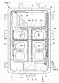
- FIG. 7 is a plan view showing a region division configuration of the case internal space of the battery pack BP of the first embodiment.
- an area division configuration of the case internal space of the battery pack BP will be described.
- the battery pack BP of the first embodiment has a battery module mounting area 7 on the vehicle rear side and a vehicle front side with the boundary line L drawn in the vehicle width direction as the internal space of the battery pack case 1. It is divided into two vehicle front-rear direction regions of the electrical component mounting region 8 on the side.
- the battery module mounting area 7 occupies most of the internal space of the case from the vehicle rear end to the boundary line L closer to the vehicle front.
- the electrical component mounting area 8 occupies an area narrower than the battery module mounting area 7 from the vehicle front end to the boundary line L closer to the vehicle front.
- the battery module mounting area 7 is divided into three divided rectangular areas of a first divided rectangular area 71, a second divided rectangular area 72, and a third divided rectangular area 73 by a T-shaped path (a central path 36 and a crossing path 37).
- the first battery module 21 having the LB controller 6 on one side surface is mounted on the first divided rectangular area 71.
- the second battery module 22 is mounted in the second divided rectangular area 72.
- the third battery module 23 is mounted in the third divided rectangular area 73.
- the electrical component mounting area 8 is divided into three divided areas, a first divided area 81, a second divided area 82, and a third divided area 83, which are divided in the vehicle width direction.
- the temperature control air unit 3 is mounted from the first section area 81 to the lower part of the second section area 82.
- the SD switch 4 is mounted on the upper part of the second section area 82.
- the junction box 5 is mounted in the third section area 83.
- a temperature adjustment air passage for ensuring the internal circulation of the temperature adjustment air produced by the temperature adjustment air unit 3 is provided, and each battery module 21, 22, 23 is divided into rectangular regions. It is formed using the gap when mounted.
- the temperature control air passage includes a central passage 36 where the temperature control air blown from the temperature control air unit 3 first flows, a cross passage 37 that divides the flow from the central passage 36 into both sides in the vehicle width direction, And an annular passage 38 for returning the temperature-controlled air flowing into the outer periphery of the space to the temperature-controlled air unit 3.
- the central passage 36 is formed by providing a gap between the opposing surfaces of the second battery module 22 and the third battery module 23.
- the crossing passage 37 is formed by providing a gap between the opposing surfaces of the first battery module 21 and the second and third battery modules 22 and 23.
- the annular passage 38 is formed by providing a clearance margin between the battery pack lower frame 11 and each pack component 2, 3, 4, 5, 6.
- the pack components 2, 3, 4, 5, 6 are mounted in the case internal space
- the gaps, intervals, and spaces formed by doing so are also included.
- the stack gap of the battery cells as the constituent elements becomes the temperature adjustment air passage by being in the same direction as the flow direction of the temperature adjustment air.
- the mounting interval of 4 flat battery cells and 5 flat battery cells, the mounting interval of 5 flat battery cells and 5 flat battery cells Becomes a temperature-controlled air passage.
- a space formed between the inner surface of the battery pack upper cover 12 and the components of the temperature control air unit 3 and the junction box 5 serves as a temperature control air passage.
- Bus bar connection configuration of battery high voltage circuit 8 and 9 show the bus bar connection configuration of the battery high-voltage circuit in the battery pack structure of the first embodiment. Hereinafter, the bus bar connection configuration of the battery high-voltage circuit will be described with reference to FIGS. 8 and 9.
- the battery high-voltage circuit of the battery pack BP of the first embodiment includes each battery module 21, 22, 23 having an internal bus bar (not shown), the junction box 5, and the SD switch 4. It is formed by a bus bar connection configuration in which connection is made via an external bus bar 90.
- the junction box 5 and the charge / discharge connector terminal 14 are connected via a high-voltage harness 91.
- the internal bus bar is a conductive plate connected to terminals of a plurality of battery cells constituting each battery module 21, 22, 23.
- the external bus bar 90 is a conductive plate that connects between the terminals of the internal bus bar so as to constitute a battery high-power circuit described below.
- the first external bus bar 90a, the second external bus bar 90b, and the third external bus bar 90c are connected to each other. Have. As shown in FIG. 9, the first external bus bar 90 a is provided at a side surface position along the intersecting passage 37 of the first battery module 21. As shown in FIG. 9, the second external bus bar 90 b and the third external bus bar 90 c are provided at both side surface positions along the central passage 36 of the second battery module 22 and the third battery module 23, respectively.
- the weak electrical harness connection configuration of the junction box 5 and the LB controller 6 As the harness connection configuration between the pack components of the battery pack BP of the first embodiment, the weak electrical harness connection configuration of the junction box 5 and the LB controller 6, the high electrical harness connection configuration of the battery module 2 and the LB controller 6, and the battery module 2 And a low-electricity harness connection configuration of the LB controller 6.
- the junction box 5 and the LB controller 6 include an annular passage 38 among the temperature-controlled air passages formed in the internal space of the battery pack case 1. It is arrange
- the weak electric harness 96 (harness) which connects the junction box 5 and the LB controller 6 is routed along the straight path part 38a extended in the vehicle front-back direction.
- the junction box 5 is disposed in the electric component mounting area 8 and at the end portion in the vehicle width direction facing the straight passage portion 38a.
- the LB controller 6 is in the first divided rectangular area 71 on which the first battery module 21 in which a plurality of battery cells are stacked vertically in the vehicle width direction is mounted, and the end position in the vehicle width direction facing the straight path portion 38a. Are arranged vertically.
- the light electrical harness 96 bundles the battery current detection signal line 96a from the current sensor 53 in the junction box 5 and also bundles the control signal line 96b from the LB controller 6 to the external electronic control system. It is a thing.
- the battery current detection signal line 96a supplies battery current information that changes with charge / discharge to the LB controller 6.
- the control signal line 96b sends battery capacity information, battery temperature information, and battery voltage information acquired by the LB controller 6 to an external electronic control system.
- the relay circuit in the junction box 5 opens and closes based on on / off information of the relay circuit sent from the external electronic control system via the control signal line 96b.
- the battery module 2 and the LB controller 6 include each battery module 21 in the temperature control air passage formed in the internal space of the battery pack case 1.
- the LB controller 6 is disposed at a position facing the crossing passage 37 where one side surfaces of the two, 23 and 23 are exposed.
- the high-voltage harness 97 which connects each external bus-bar 90a, 90b, 90c and LB controller 6 is routed along the cross path 37 extended in a vehicle width direction.
- the high-voltage harness 97 is a bundle of the first battery voltage detection line 97a, the second battery voltage detection line 97b, and the third battery voltage detection line 97c.
- the first battery voltage detection line 97a is connected to the end position of the first external bus bar 90a on the side close to the LB controller 6.
- the second battery voltage detection line 97b and the third battery voltage detection line 97c are connected to two end positions of the second external bus bar 90b and the third external bus bar 90c on the side close to the intersection passage 37.
- the high-voltage harness 97 protrudes upward from the upper surfaces of the second and third battery modules 22 and 23 among the three side surfaces of the battery modules 21, 22, and 23 that face each other via the cross passage 37.
- the first battery module 21 is routed along the upper side surface portion.
- the battery voltage detection lines 97a, 97b, and 97c of the high-voltage harness 97 supply the battery voltage values of the battery modules 21, 22, and 23 to the LB controller 6.
- the LB controller 6 not only acquires battery voltage information based on the supplied battery voltage value, but also acquires battery capacity information based on the relationship characteristics between the battery voltage value and the battery capacity. Incidentally, in the case of a lithium ion battery, the battery voltage value and the battery capacity have a linear relationship.
- the battery module 2 and the LB controller 6 are arranged in the battery module mounting area 7 in the internal space of the battery pack case 1 as shown in FIG. .
- the thermocouple temperature sensor contact 24 of the thermocouple temperature sensor provided in each battery module 21, 22, and 23 and the weak electric harness 98 that connects the LB controller 6 are routed by a route in the case space.
- the wiring path of the weak electrical harness 98 is along the path along both straight path portions 38a and 38b of the annular path 38 extending in the vehicle front-rear direction and along the stepwise surface of the second and third battery modules 22 and 23 in the vehicle width direction. The route is used.
- the temperature measuring contact 24 is provided on the outer peripheral side surface exposed to the annular passage 38 of each battery module 21, 22, 23 as shown in FIGS. 10 and 11. For example, two contact points are provided on the outer peripheral side surface of the first battery module 21 and four contact points are provided on the outer peripheral side surfaces of the second battery module 22 and the third battery module 23, respectively.
- a thermocouple temperature sensor in addition to the temperature measuring contact 24, it has a reference contact (cold junction) to which a reference voltage is applied by a conducting wire.
- the light electrical harness 98 is a bundle of temperature detection signal lines from a plurality of temperature measuring contacts 24, and supplies the temperature detection signals of the battery modules 21, 22, and 23 to the LB controller 6. To do.
- the LB controller 6 acquires battery temperature information from the supplied temperature detection signal.
- a battery pack BP equipped with a secondary battery such as a lithium ion battery corresponds to a fuel tank for an engine vehicle, and is repeatedly charged for increasing the battery capacity and discharged for decreasing the battery capacity.
- a secondary battery such as a lithium ion battery
- the charging port lid at the front of the vehicle is opened, and the quick charging connector on the stand side is inserted into the quick charging port 115 on the vehicle side.
- a direct current rapid charging voltage is transmitted to the DC / DC converter of the high voltage module 112 via the rapid charging harness 117, and is converted into a direct current charging voltage by voltage conversion in the DC / DC converter.
- This DC charging voltage is transmitted to the battery pack BP via the charging / discharging harness 111, passes through the junction box 5 and the bus bar in the battery pack BP, and is charged to the battery cells of the battery modules 21, 22, and 23.
- the charging port lid at the front of the vehicle is opened, and the normal charging connector on the home power supply side is inserted into the normal charging port 116 on the vehicle side.
- an AC normal charging voltage is transmitted to the charger of the high voltage module 112 via the normal charging harness 118, and a DC charging voltage is obtained by voltage conversion and AC / DC conversion in the charger.
- This DC charging voltage is transmitted to the battery pack BP via the charging / discharging harness 111, passes through the junction box 5 and the bus bar in the battery pack BP, and is charged to the battery cells of the battery modules 21, 22, and 23.
- the DC battery voltage from each of the battery modules 21, 22 and 23 is discharged from the battery pack BP via the bus bar and the junction box 5.
- the discharged DC battery voltage is transmitted to the DC / DC converter of the high voltage module 112 via the charge / discharge harness 111, and is converted into a DC drive voltage by voltage conversion in the DC / DC converter.
- This DC drive voltage is converted to an AC drive voltage by DC / AC conversion in the inverter 113.
- This AC drive voltage is applied to the travel motor of the motor drive unit 114, and rotationally drives the travel motor.
- the travel motor exhibits the generator function, and converts rotational energy input from the drive tire into generated energy.
- the AC generated voltage generated by the generated energy is converted into a DC generated voltage by AC / DC conversion at the inverter 113, and is converted into a DC charging voltage by voltage conversion at the DC / DC converter of the high voltage module 112.
- This DC charging voltage is transmitted to the battery pack BP via the charging / discharging harness 111, passes through the junction box 5 and the bus bar in the battery pack BP, and is charged to the battery cells of the battery modules 21, 22, and 23.
- the temperature control operation of the battery pack BP performed by the temperature controller 52 will be described.
- the PTC heater of the temperature control air unit is energized and the blower fan is turned on.
- the blower fan is turned on.
- heat is applied to the wind passing through the PTC heater to create warm air.
- the internal temperature of the battery pack BP can be maintained in the range of the first set temperature to the second set temperature at which high battery performance is obtained. At this time, it is important to circulate the temperature-controlled air uniformly and smoothly over the entire space inside the case so that there is no space where the amount of temperature-controlled air circulation is insufficient. The reason is that the internal temperature control of the battery pack BP uses the temperature of the first battery module 21, the second battery module 22, and the third battery module 23 mounted in the internal space of the case as the battery temperature at which high performance is exhibited. By aiming to maintain in the area.
- the internal space circulation action of the temperature-controlled air will be described.
- the temperature-controlled air (cold air, hot air) blown from the air outlet of the temperature-control air unit 3 first flows from the front of the vehicle toward the rear of the vehicle through the central passage 36 as indicated by an arrow D in FIG. And, as indicated by arrows E and E in FIG. 5, the flow from the central passage 36 is divided into both sides in the vehicle width direction by the intersection passage 37 that intersects the central passage 36. That is, the T-shaped passage formed by the central passage 36 and the intersection passage 37 is a main passage that allows temperature-controlled air to flow.
- the temperature-controlled air flowing through the T-shaped passage branches in multiple directions in the middle of the flow, and exchanges heat with the first battery module 21, the second battery module 22, and the third battery module 23 as described below.
- the heat exchange of the first battery module 21 is performed by using the temperature control air flowing separately on both sides in the vehicle width direction of the intersection passage 37 shown by arrows E and E in FIG. 5 and the cell stacking gap shown by arrow F in FIG. To the temperature control air flowing toward the rear of the vehicle.
- the heat exchange between the second battery module 22 and the third battery module 23 is indicated by the temperature-controlled air flowing from the front of the vehicle toward the rear of the vehicle through the central passage 36 indicated by the arrow D in FIG. 5 and arrows E and E in FIG. It is performed between the temperature control airflow that divides the intersection passage 37 on both sides in the vehicle width direction. In addition to this, it is performed between the four-packed battery cells indicated by arrows G and G in FIG.
- the wind after heat exchange between the first battery module 21, the second battery module 22, and the third battery module 23 flows into the annular passage 38 formed in the outer periphery of the internal space.
- the wind after heat exchange flowing into the annular passage 38 is divided into both sides in the vehicle width direction at the vehicle rear side passage portion along the first battery module 21 as shown by arrows I and I in FIG.
- the two divided winds after the heat exchange flow through the vehicle side passages from the vehicle rear toward the vehicle front, and merge at the vehicle front side passages. Then, it is returned to the suction side of the temperature control unit 3.
- the air after the heat exchange returned to the unit suction side passes through the evaporator 33 and the blower fan 32 in the unit case 31 as shown by the arrow in FIG. 6, and then the PTC provided in the temperature control air duct 35. After passing through the heater 34, the air is blown out from the duct outlet to the central passage 36. At this time, when the refrigerant is introduced into the evaporator 33, the energization of the PTC heater 34 is stopped, and the blower fan 32 is turned, heat is taken away by the evaporator 33 from the wind after heat exchange, and cold wind is created.
- the PTC heater 34 is energized, and the blower fan 32 is turned, heat is applied from the PTC heater 34 to the wind after the heat exchange passing through the PTC heater 34, and the warm air is generated. Produced.
- the central passage 36, the intersecting passage 37, and the annular passage 38 are formed in the internal space of the case, and the heat-controlled air that has been merged from the two systems is sucked into the central passage.
- positions the temperature control air unit 3 in the position which blows off to 36 was employ
- the internal temperature fluctuation range of the battery pack BP can be suppressed to a narrow range.
- the internal temperature of the battery pack BP can be maintained in the optimum temperature range that exhibits the intended high battery performance.
- the LB controller 6 includes four high-power connector terminals 61, 62, 63, 64 and two low-power connector terminals 65, 66 as shown in FIG. These connector terminals 61, 62, 63, 64, 65, 66 are connected with a weak electric harness 96, a high electric harness 97, and a low electric harness 98.
- the harness connecting action by the light electrical harness 96 will be described.
- the weak electric harness 96 is routed along the straight passage portion 38 a of the annular passage 38, and the weak electric harness 96 is stopped at a plurality of positions by a fixture. Then, one of the connectors provided at both ends of the light electrical harness 96 is connected to the connector on the junction box 5 side. The other of the connectors provided at both ends of the weak electric harness 96 is inserted into the low electric connector terminal 66 as shown in FIG. As a result, the junction box 5 and the LB controller 6 are connected via the weak electrical harness 96.
- the harness connecting action by the high-voltage harness 97 will be described.
- the high-voltage harness 97 is routed along the crossing passage 37, and the high-voltage harness 97 is stopped at a plurality of locations by fixtures. Then, one of the connectors provided at both ends of the high voltage harness 97 is connected to the connector provided at the end of each voltage detection line 97a, 97b, 97c.
- the other connector provided at both ends of the high-voltage harness 97 is inserted into the four high-voltage connector terminals 61, 62, 63, 64 as shown in FIG. Thereby, each battery module 21, 22, 23 and the LB controller 6 are connected via the high-voltage harness 97.
- the weak electric harness 98 has stepped surfaces in the vehicle width direction of the linear passage portions 38 a and 38 b of the annular passage 38 extending in the vehicle longitudinal direction and the second and third battery modules 22 and 23. And route along. Then, the weak electrical harness 98 is stopped at a plurality of positions by a fixture, and one of the connectors provided at both ends of the weak electrical harness 98 is connected to the connector provided at the end of each temperature detection signal line. The other of the connectors provided at both ends of the weak electric harness 98 is inserted into the low electric connector terminal 65 shown in FIG. As a result, the battery modules 21, 22, and 23 and the LB controller 6 are connected via the weak electrical harness 98.
- the weak electrical harness 96 simply routes a short harness in a straight line along the straight passage portion 38 a of the annular passage 38.
- the high-power harness 97 simply routes a short harness along the intersection passage 37 in a straight line.
- the weak electrical harness 98 is only routed in an H shape in plan view along the outer peripheral surface of each battery module 21, 22, 23. In other words, it is not necessary to route each harness while bending it in a complicated manner along corners and grooves, etc., and harness routing workability is improved and harness durability is improved compared to harness routing on a curved path. To do.
- the junction box 5 and the LB controller 6 that are respectively arranged at positions away from the straight passage portion 38a in the temperature-controlled air passage are arranged along the straight passage portion 38a.
- the structure connected by the harness 96 was employ
- the light electrical harness 96 routed in one straight passage portion 38a of the annular passage 38 in the temperature adjustment air passage follows the flow of the temperature adjustment air flowing through the straight passage portion 38a as shown in FIG. It becomes a harness that extends straight.
- the passage resistance of the temperature control air passage is suppressed low, and the smooth flow of temperature control air is ensured.
- the harness connection between the junction box 5 and the LB controller 6, as described above the smooth flow of the temperature-controlled air can be ensured while improving the harness routing workability and the harness durability.
- the internal space of the battery pack case 1 is divided in the vehicle front-rear direction to form a battery module mounting area 7 and an electrical component mounting area 8, and the junction box 5 is disposed in the electrical component mounting area 8.
- the configuration was adopted (FIG. 7).
- the junction box is disposed in the battery module mounting area and is located at a position at an interval between two battery modules arranged in the vehicle width direction (position corresponding to the central passage 36 in the first embodiment).
- the mounting width in the vehicle width direction of the two battery modules is the width excluding the occupied width of the junction box, and the battery mounting space is reduced.
- the junction box 5 by arranging the junction box 5 in the electrical component mounting area 8 separated from the battery module mounting area 7, the junction box 5 does not cause a reduction in the mounting width of the battery module 2 in the vehicle width direction. Battery mounting space is secured.
- a temperature control air passage is used as a comparative example in which two battery modules arranged in the vehicle width direction are opposed to each other.
- the junction box is arranged in the temperature-controlled air passage so that the junction box narrows the cross-sectional area of the passage through which the temperature-controlled air flows.
- the junction box 5 is arranged in the electrical component mounting area 8 separated from the battery module mounting area 7, in other words, the junction box 5 is arranged so as to be out of the temperature control air passage. For this reason, the junction box 5 does not become a factor of narrowing the passage cross-sectional area through which the temperature-controlled air flows, and the flow rate of the temperature-controlled air flowing through the battery module mounting region 7 is ensured.
- the battery module mounting area 7 is divided into a plurality of divided rectangular areas 71, 72, 73 on which a plurality of battery modules 21, 22, 23 are mounted.
- the LB controller 6 is vertically stacked in the first divided rectangular area 71 on which the first battery module 21 in which the battery cells are vertically stacked in the vehicle width direction is mounted among the plurality of divided rectangular areas 71, 72, 73.
- the structure to adopt was adopted (FIG. 9).
- the battery module mounting area is divided into a plurality of divided rectangular areas in which only a plurality of battery modules are mounted, and the LB controller is arranged in an area outside the plurality of divided rectangular areas as a comparative example.
- the LB controller arranged in the area outside the divided rectangular area becomes a factor for narrowing the temperature adjusting air passage.
- the LB controller 6 does not become a factor that narrows the passage sectional area through which the temperature-controlled air flows. A flow of temperature-controlled air flowing in the case internal space is ensured.
- a LB controller in a plurality of divided rectangular areas, but arranged in a flat stack is used as a comparative example.
- the area occupied by the stacked LB controllers is increased, and the battery mounting space is reduced accordingly.
- the LB controller 6 is vertically stacked with the battery cells, so that the area occupied by the LB controller 6 can be kept small, and the maximum battery mounting space can be achieved while the LB controller 6 is mounted in the battery module mounting area 7. Is secured.
- the annular passage 38 for returning the temperature adjustment air flowing into the outer periphery of the case internal space to the temperature adjustment air unit 3 is provided. It was a passage with. And the structure which makes the straight channel
- the case-circulating action of the temperature-controlled air in the case is that the T-shaped passage formed by the central passage 36 and the intersection passage 37 is a main passage through which the temperature-controlled air flows. Therefore, when the case where the light electrical harness 96 is routed in the central passage 36 or the crossing passage 37 is compared with the case where the light electrical harness 96 is routed in the annular passage 38, the case where the light electrical harness 96 is routed in the central passage 36 or the crossing passage 37. However, the reduction width of the case internal space circulation efficiency becomes large.
- the passage formed on one side of the case as a part of the annular passage 38 on one side of the vehicle width direction is a straight passage portion 38a for routing the light electrical harness 96, the internal space circulation efficiency of the case is improved. The decrease is kept small.
- an internal space of the battery module 2 includes a battery cell assembly, a junction box 5 that supplies / cuts off / distributes strong power using a relay circuit, and a battery controller (LB controller 6 that performs battery management).
- a gap that is secured when the battery module 2 is mounted in the internal space of the battery pack case 1 is a temperature-controlled air passage through which the temperature-controlled air flows.
- the junction box 5 and the battery controller (LB controller 6) are arranged at positions separated from each other so as to face one linear passage portion 38a in the temperature adjusting air passage, and the junction box 5 and the battery controller (LB controller 6) are arranged.
- the internal space of the battery pack case 1 is divided in the vehicle front-rear direction to form a battery module mounting area 7 and an electrical component mounting area 8, and the junction box 5 is disposed in the electrical component mounting area 8. did.
- the junction box 5 does not cause a reduction in the mounting width of the battery module 2 in the vehicle width direction, and a battery mounting space can be secured, and the junction box 5 can be temperature controlled.
- the flow rate of the temperature-controlled air flowing through the battery module mounting area 7 can be ensured without causing a reduction in the cross-sectional area of the passage through which the wind flows.
- the battery module mounting area 7 is divided into a plurality of divided rectangular areas 71, 72, 73 for mounting a plurality of battery modules 21, 22, 23, and the battery controller (LB controller 6) is Of the divided rectangular areas 71, 72, 73, the battery cells are vertically stacked in a divided rectangular area (first divided rectangular area 7) on which a battery module (first battery module 21) in which the battery cells are vertically stacked is mounted. did. For this reason, in addition to the effect of (2), the battery controller (LB controller 6) does not become a factor of narrowing the passage cross-sectional area through which the temperature adjustment air flows, and ensures the flow rate of the temperature adjustment air flowing in the case internal space. In addition, it is possible to secure the maximum battery mounting space while mounting the battery controller (LB controller 6) in the battery module mounting area 7.
- the temperature control air passage is a passage having an annular passage 38 for returning the temperature control air flowing into the outer periphery of the case internal space after heat exchange with the plurality of battery modules 21, 22, and 23.
- the passage portion 38a is a passage formed on one side of the case as a part of the annular passage 38 on both sides in the vehicle width direction.
- Example 1 As mentioned above, although the battery pack structure of the electric vehicle of this invention has been demonstrated based on Example 1, it is not restricted to this Example 1 about a concrete structure, It concerns on each claim of a claim Design changes and additions are allowed without departing from the scope of the invention.
- the battery modules 21, 22, and 23 are divided into three divided rectangular areas 71, 72, and 73, respectively.
- the battery module may be an example of one module, may be an example of a battery module that is divided into two, or may be an example of a battery module that is divided into four or more parts.
- the division method is not limited to the method of dividing by the T-shaped passage as in the first embodiment, and examples of various division methods may be used.
- Example 1 the case internal space is divided into the battery module mounting area 7 and the electrical component mounting area 8 in the vehicle front-rear direction, and the junction box 5 is arranged in the electrical component mounting area 8.
- the junction box is disposed away from the LB controller without dividing the battery module mounting area and the electrical component mounting area may be possible.
- the LB controller 6 is placed in the first divided rectangular area 71 in which the first battery module 71 in which the battery cells are stacked vertically in the vehicle width direction is mounted among the plurality of divided rectangular areas 71, 72, 73.
- An example of vertical stacking was shown.
- the LB controller is arranged away from the junction box without dividing the battery module mounting area and the electrical component mounting area may be possible.
- Example 1 shows an example in which the straight passage portion 38a is a passage formed on one side of the case among both sides in the vehicle width direction as a part of the annular passage 38 for returning the temperature-controlled air after heat exchange.
- the straight passage portion for routing the harness is not limited to a partial passage of the annular passage that returns the temperature-controlled air after heat exchange. It may be a passage in the width direction or a passage in the vehicle front-rear direction.
- Example 1 shows an example in which the battery pack structure of the present invention is applied to a one-box type electric vehicle equipped with only a traveling motor as a traveling drive source.
- the battery pack structure of the electric vehicle according to the present invention can be applied to various electric vehicles such as a sedan type, a wagon type, and an SUV type in addition to the one-box type.
- the present invention can also be applied to a hybrid type electric vehicle (hybrid electric vehicle) equipped with a traveling motor and an engine as a traveling drive source. In short, it can be applied to any electric vehicle including a battery pack equipped with a battery module, a junction box, and a battery controller.
Landscapes
- Engineering & Computer Science (AREA)
- Chemical & Material Sciences (AREA)
- General Chemical & Material Sciences (AREA)
- Electrochemistry (AREA)
- Chemical Kinetics & Catalysis (AREA)
- Manufacturing & Machinery (AREA)
- Transportation (AREA)
- Mechanical Engineering (AREA)
- Power Engineering (AREA)
- Aviation & Aerospace Engineering (AREA)
- Life Sciences & Earth Sciences (AREA)
- Sustainable Energy (AREA)
- Sustainable Development (AREA)
- Combustion & Propulsion (AREA)
- Secondary Cells (AREA)
- Battery Mounting, Suspending (AREA)
- Arrangement Or Mounting Of Propulsion Units For Vehicles (AREA)
- Electric Propulsion And Braking For Vehicles (AREA)
Abstract
A battery module (2), a junction box (5), and an LB controller (6) are mounted in the internal space of a battery pack case (1). A gap secured when the battery module (2) is installed in the internal space of the battery pack case (1) is used as a temperature adjustment air passage wherein temperature-adjusting air flows. The junction box (5) and the LB controller (6) are each arranged at separated positions facing one straight passage section (38a) of the temperature adjustment air passage. A weak-current harness (96) connecting the junction box (5) and the LB controller (6) is wired along the straight passage section (38a). As a result, smooth flow of temperature-adjusting air can be maintained in the harness connection of the junction box and the battery controller, while improving the workability of the harness wiring and the durability of the harness.
Description
本発明は、バッテリパックケースの内部空間に、バッテリモジュールとジャンクションボックスとバッテリコントローラを搭載した電気自動車のバッテリパック構造に関する。
The present invention relates to a battery pack structure for an electric vehicle in which a battery module, a junction box, and a battery controller are mounted in the internal space of the battery pack case.
電気自動車のバッテリパックは、バッテリパックケースの内部空間に、バッテリセルの集合体であるバッテリモジュールと、リレー回路により強電の供給/遮断/分配を行うジャンクションボックスと、バッテリ管理を行うバッテリコントローラと、を搭載している。このバッテリパックにおいて、バッテリモジュールとジャンクションボックスとバッテリコントローラを、強電線を束ねた強電ハーネスや弱電線を束ねた弱電ハーネスにより互いに接続した構造が例えば特許文献1として知られている。
The battery pack of an electric vehicle includes a battery module that is an assembly of battery cells, a junction box that supplies / cuts off / distributes strong power using a relay circuit, a battery controller that performs battery management, and an internal space of the battery pack case, It is equipped with. In this battery pack, for example, Patent Document 1 discloses a structure in which a battery module, a junction box, and a battery controller are connected to each other by a high-power harness that bundles strong wires or a weak-power harness that bundles weak wires.
しかしながら、特許文献1に記載されたバッテリパック構造にあっては、ケース内部空間を三つの分割矩形領域に区分し、三つの分割矩形領域のそれぞれにバッテリモジュールを搭載している。このとき三つのバッテリモジュールの対向側面によるT字状の隙間を、ジャンクションボックスの搭載スペースにすると共にハーネス配索経路としている。このため、互いに離れた位置に搭載されたジャンクションボックスとバッテリコントローラをハーネス接続する際、曲がった隙間経路に沿って曲げながらハーネスを配索する必要がある。この結果、ハーネス配索作業性が低いし、ハーネス耐久性を低下させてしまう、という問題があった。
However, in the battery pack structure described in Patent Document 1, the internal space of the case is divided into three divided rectangular areas, and a battery module is mounted in each of the three divided rectangular areas. At this time, a T-shaped gap formed by the opposite side surfaces of the three battery modules is used as a mounting space for the junction box and a harness routing route. For this reason, when connecting the junction box and the battery controller mounted at positions separated from each other by harness, it is necessary to route the harness while bending it along a bent clearance path. As a result, there is a problem that harness wiring workability is low and harness durability is lowered.
一方、バッテリパックケースの内部空間に複数のバッテリモジュールを搭載したときに確保される隙間は、バッテリ温度を管理する温調風を流す温調風通路として利用される。このように、複数のバッテリモジュールを搭載したときに確保される隙間を、温調風通路とハーネス配索経路として兼用すると、温調風が流れる隙間に、温調風の流れを乱すように曲がったハーネスが配索される。この結果、ハーネスが通路抵抗となって温調風のスムーズな流れを確保できない、という問題があった。
On the other hand, the clearance secured when a plurality of battery modules are mounted in the internal space of the battery pack case is used as a temperature-controlled air passage for supplying temperature-controlled air for managing the battery temperature. In this way, if the gap secured when multiple battery modules are mounted is used as the temperature adjustment air passage and the harness routing route, the temperature adjustment air will bend in the gap where the temperature adjustment air flows. A harness is routed. As a result, there is a problem that the harness becomes passage resistance and a smooth flow of temperature-controlled air cannot be secured.
本発明は、上記問題に着目してなされたもので、ジャンクションボックスとバッテリコントローラのハーネス接続において、ハーネス配索作業性やハーネス耐久性を向上させながら、温調風のスムーズな流れを確保することができる電気自動車のバッテリパック構造を提供することを目的とする。
The present invention has been made paying attention to the above-mentioned problem, and in the harness connection between the junction box and the battery controller, to ensure the smooth flow of the temperature-controlled air while improving the harness routing workability and the harness durability. An object of the present invention is to provide a battery pack structure for an electric vehicle.
上記目的を達成するため、本発明の電気自動車のバッテリパック構造は、バッテリパックケースの内部空間に、バッテリセルの集合体によるバッテリモジュールと、リレー回路により強電の供給/遮断/分配を行うジャンクションボックスと、バッテリ管理を行うバッテリコントローラと、を搭載したものを前提とする。
この電気自動車のバッテリパック構造において、前記バッテリパックケースの内部空間に前記バッテリモジュールを搭載したときに確保される隙間を、温調風が流れる温調風通路とした。前記ジャンクションボックスと前記バッテリコントローラを、前記温調風通路のうち一つの直線通路部に臨む離れた位置にそれぞれ配置した。また、前記ジャンクションボックスと前記バッテリコントローラを接続するハーネスを、前記直線通路部に沿って配索した。 In order to achieve the above object, a battery pack structure for an electric vehicle according to the present invention is a junction box that supplies / cuts off / distributes high power by a battery module in a battery pack case and a relay circuit in an internal space of the battery pack case. And a battery controller that performs battery management.
In the battery pack structure of the electric vehicle, the gap that is secured when the battery module is mounted in the internal space of the battery pack case is defined as a temperature adjustment air passage through which the temperature adjustment air flows. The junction box and the battery controller are respectively arranged at positions separated from one of the temperature control air passages so as to face one straight passage portion. Moreover, the harness which connects the said junction box and the said battery controller was routed along the said linear channel | path part.
よって、ジャンクションボックスとバッテリコントローラは、バッテリパックケースの内部空間に形成された温調風通路のうち一つの直線通路部に臨む離れた位置にそれぞれ配置され、この直線通路部に沿って配索されたハーネスにより接続される。
したがって、ジャンクションボックスとバッテリコントローラをハーネス接続する際、一つの直線通路部に沿わせるだけの簡素化されたハーネス配索作業となる。このため、曲がった経路へのハーネス配索に比べ、ハーネス配索作業性が向上するし、ハーネス耐久性が向上する。
さらに、温調風通路のうち一つの直線通路部に配索されるハーネスは、直線通路部を流れる温調風の流れに沿うように真っ直ぐに延びるハーネスになる。このため、温調風の流れを乱すように曲がったハーネスが配索される場合に比べ、温調風通路の通路抵抗が低く抑えられ、温調風のスムーズな流れが確保される。
この結果、ジャンクションボックスとバッテリコントローラのハーネス接続において、ハーネス配索作業性やハーネス耐久性を向上させながら、温調風のスムーズな流れを確保することができる。 Therefore, the junction box and the battery controller are respectively arranged at positions separated from one of the temperature-controlled air passages formed in the internal space of the battery pack case and facing the straight passage portion, and are routed along the straight passage portion. Connected by a harness.
Therefore, when the junction box and the battery controller are connected to each other by a harness, a simplified harness routing operation is performed so as to be along one straight path portion. For this reason, compared with the harness wiring to the curved path | route, harness wiring workability | operativity improves and harness durability improves.
Furthermore, the harness routed in one straight passage portion of the temperature control air passage is a harness that extends straight along the flow of the temperature control air flowing through the straight passage portion. For this reason, compared with the case where the harness bent so that the flow of temperature control air may be disturbed, the passage resistance of the temperature control air passage is suppressed low, and the smooth flow of temperature control air is ensured.
As a result, in the harness connection between the junction box and the battery controller, it is possible to ensure a smooth flow of temperature-controlled air while improving harness routing workability and harness durability.
以下、本発明の電気自動車のバッテリパック構造を実現する最良の形態を、図面に示す実施例1に基づいて説明する。
Hereinafter, the best mode for realizing the battery pack structure of an electric vehicle of the present invention will be described based on Example 1 shown in the drawings.
まず、実施例1の電気自動車のバッテリパック構造における構成を、「バッテリパックBPの車載構成」、「バッテリパックBPのパック構成要素」、「バッテリパックBPのケース内部空間の領域区分構成」、「バッテリ強電回路のバスバー接続構成」、「パック構成要素間のハーネス接続構成」に分けて説明する。
First, the configuration of the battery pack structure of the electric vehicle according to the first embodiment is described as “in-vehicle configuration of battery pack BP”, “pack component of battery pack BP”, “region division configuration of case internal space of battery pack BP”, “ The description will be divided into “Bus bar connection configuration of battery high power circuit” and “Harness connection configuration between pack components”.
[バッテリパックBPの車載構成]
図1及び図2は、実施例1の構造を採用したバッテリパックBPが搭載されたワンボックスタイプの電気自動車を示す概略側面図及び概略底面図である。以下、図1及び図2に基づき、バッテリパックBPの車載構成を説明する。 [In-vehicle configuration of battery pack BP]
1 and 2 are a schematic side view and a schematic bottom view showing a one-box type electric vehicle on which a battery pack BP employing the structure of the first embodiment is mounted. Hereinafter, the in-vehicle configuration of the battery pack BP will be described with reference to FIGS. 1 and 2.
前記バッテリパックBPは、図1に示すように、車体フロア100の下部のホイールベース中央部位置に配置される。車体フロア100は、モータ室101と車室102を画成するダッシュパネル104との接続位置から、車室102に連通する荷室103を確保する車両後端位置まで設けられ、車両前方から車両後方までのフロア面凹凸を抑えたフラット形状としている。車室102には、インストルメントパネル105と、センターコンソールボックス106と、エアコンユニット107と、乗員シート108と、を有する。
The battery pack BP is disposed at the center of the wheel base at the lower part of the vehicle body floor 100 as shown in FIG. The vehicle body floor 100 is provided from the connection position between the motor chamber 101 and the dash panel 104 that defines the vehicle compartment 102 to the vehicle rear end position that secures the luggage compartment 103 communicating with the vehicle compartment 102, from the vehicle front to the vehicle rear. Flat shape with reduced floor surface unevenness. The vehicle compartment 102 includes an instrument panel 105, a center console box 106, an air conditioner unit 107, and an occupant seat 108.
前記バッテリパックBPは、図2に示すように、車体強度部材である車体メンバに対して8点支持される。車体メンバは、車両前後方向に延びる一対のサイドメンバ109,109と、一対のサイドメンバ109,109を車幅方向に連結する複数のクロスメンバ110,110,…と、を有して構成される。バッテリパックBPの両側は、一対の第1サイドメンバ支持点S1,S1と一対の第1クロスメンバ支持点C1,C1と一対の第2サイドメンバ支持点S2,S2により6点支持される。バッテリパックBPの後側は、一対の第2クロスメンバ支持点C2,C2により2点支持されている。
As shown in FIG. 2, the battery pack BP is supported at eight points on a vehicle body member that is a vehicle body strength member. The vehicle body member includes a pair of side members 109, 109 extending in the vehicle front-rear direction and a plurality of cross members 110, 110,... Connecting the pair of side members 109, 109 in the vehicle width direction. . Both sides of the battery pack BP are supported at six points by a pair of first side member support points S1, S1, a pair of first cross member support points C1, C1, and a pair of second side member support points S2, S2. The rear side of the battery pack BP is supported at two points by a pair of second cross member support points C2 and C2.
前記バッテリパックBPは、図1に示すように、ダッシュパネル104に沿って車両前後方向に直線状に配索した充放電ハーネス111を介し、モータ室101に配置されている強電モジュール112(DC/DCコンバータ+充電器)と接続される。このモータ室101には、強電モジュール112以外に、インバータ113と、モータ駆動ユニット114(走行用モータ+減速ギヤ+デファレンシャルギヤ)と、を有する。また、車両前面位置には、充電ポートリッドを有する急速充電ポート115と普通充電ポート116が設けられる。急速充電ポート115と強電モジュール112は、急速充電ハーネス117により接続される。普通充電ポート116と強電モジュール112は、普通充電ハーネス118により接続される。
As shown in FIG. 1, the battery pack BP is connected to a high-power module 112 (DC / DC) disposed in the motor chamber 101 via a charge / discharge harness 111 that is arranged in a straight line in the vehicle longitudinal direction along the dash panel 104. DC converter + charger). In addition to the high-power module 112, the motor chamber 101 includes an inverter 113 and a motor drive unit 114 (traveling motor + reduction gear + differential gear). Further, a quick charging port 115 having a charging port lid and a normal charging port 116 are provided at the front position of the vehicle. The quick charge port 115 and the high voltage module 112 are connected by a quick charge harness 117. The normal charging port 116 and the high voltage module 112 are connected by a normal charging harness 118.
前記バッテリパックBPは、インストルメントパネル105内に配置されているエアコンユニット107を備えた空調システムと接続される。即ち、後述するバッテリモジュールが搭載されているバッテリパックBPの内部温度を温調風(冷風、温風)により管理する。なお、冷風は、空調システムから分岐冷媒管を介して冷媒をエバポレータに導入することで作り出す。温風は、空調システムからのPTCハーネスを介してPTCヒータを作動することで作り出す。
The battery pack BP is connected to an air conditioning system including an air conditioner unit 107 disposed in the instrument panel 105. That is, the internal temperature of the battery pack BP on which a battery module, which will be described later, is mounted is managed by temperature control air (cold air, hot air). In addition, cold wind is produced by introducing a refrigerant into an evaporator through a branch refrigerant pipe from an air conditioning system. Hot air is generated by operating a PTC heater via a PTC harness from the air conditioning system.
前記バッテリパックBPは、図外のCANケーブル等の双方向通信線を介し、外部の電子制御システムと接続される。即ち、バッテリパックBPは、外部の電子制御システムと情報交換に基づく統合制御により、バッテリモジュールの放電制御(力行制御)や充電制御(急速充電制御・普通充電制御・回生制御)等が行われる。
The battery pack BP is connected to an external electronic control system via a bidirectional communication line such as a CAN cable (not shown). That is, the battery pack BP performs discharge control (power running control), charge control (rapid charge control / normal charge control / regenerative control), and the like of the battery module through integrated control based on information exchange with an external electronic control system.
[バッテリパックBPのパック構成要素]
図3~図6は、実施例1のバッテリパックBPの詳細を示す図である。以下、図3~図6に基づき、バッテリパックBPのパック構成要素を説明する。 [Pack components of battery pack BP]
3 to 6 are diagrams illustrating details of the battery pack BP of the first embodiment. Hereinafter, the pack components of the battery pack BP will be described with reference to FIGS.
図3~図6は、実施例1のバッテリパックBPの詳細を示す図である。以下、図3~図6に基づき、バッテリパックBPのパック構成要素を説明する。 [Pack components of battery pack BP]
3 to 6 are diagrams illustrating details of the battery pack BP of the first embodiment. Hereinafter, the pack components of the battery pack BP will be described with reference to FIGS.
実施例1のバッテリパックBPは、図3及び図4に示すように、バッテリパックケース1と、バッテリモジュール2と、温調風ユニット3と、サービス・ディスコネクト・スイッチ4(以下、「SDスイッチ」という。)と、ジャンクションボックス5と、リチウムイオン・バッテリ・コントローラ6(以下、「LBコントローラ」という。)と、を備えていている。
As shown in FIGS. 3 and 4, the battery pack BP of the first embodiment includes a battery pack case 1, a battery module 2, a temperature control unit 3, and a service disconnect switch 4 (hereinafter referred to as “SD switch”). ”), A junction box 5, and a lithium ion battery controller 6 (hereinafter referred to as“ LB controller ”).
前記バッテリパックケース1は、図3及び図4に示すように、バッテリパックロアフレーム11とバッテリパックアッパーカバー12の2部品によって構成される。
The battery pack case 1 is composed of two parts, a battery pack lower frame 11 and a battery pack upper cover 12, as shown in FIGS.
前記バッテリパックロアフレーム11は、図4に示すように、車体メンバに対し支持固定されるフレーム部材である。このバッテリパックロアフレーム11には、バッテリモジュール2や他のパック構成要素3,4,5,6を搭載する方形凹部による搭載空間を有する。このバッテリパックロアフレーム11のフレーム前端縁には、冷媒管コネクタ端子13と弱電コネクタ端子16と充放電コネクタ端子14と車室内空調用に強電を供給する強電コネクタ端子15が取り付けられている。
The battery pack lower frame 11 is a frame member that is supported and fixed to the vehicle body member as shown in FIG. The battery pack lower frame 11 has a mounting space formed by a rectangular recess in which the battery module 2 and other pack components 3, 4, 5, and 6 are mounted. At the frame front end edge of the battery pack lower frame 11, a refrigerant pipe connector terminal 13, a low-power connector terminal 16, a charge / discharge connector terminal 14, and a high-power connector terminal 15 for supplying high power for vehicle interior air conditioning are attached.
前記バッテリパックアッパーカバー12は、図3に示すように、バッテリパックロアフレーム11の外周部位置にボルト固定されるカバー部材である。このバッテリパックアッパーカバー12には、バッテリパックロアフレーム11に搭載される各パック構成要素2,3,4,5,6のうち、特にバッテリモジュール2の凹凸高さ形状に対応した凹凸段差面形状によるカバー面を有する。
The battery pack upper cover 12 is a cover member that is bolted to the outer peripheral portion of the battery pack lower frame 11 as shown in FIG. The battery pack upper cover 12 has an uneven step surface shape corresponding to the uneven height shape of the battery module 2 among the pack components 2, 3, 4, 5, 6 mounted on the battery pack lower frame 11. With a cover surface.
前記バッテリモジュール2は、図4及び図5に示すように、バッテリパックロアフレーム11に搭載され、第1バッテリモジュール21と第2バッテリモジュール22と第3バッテリモジュール23との3分割モジュールにより構成される。各バッテリモジュール21,22,23は、二次電池(リチウムイオンバッテリ等)による複数のバッテリセルを積み重ねた集合体構造であり、各バッテリモジュール21,22,23の詳しい構成は、下記の通りである。
As shown in FIGS. 4 and 5, the battery module 2 is mounted on the battery pack lower frame 11, and is configured by a three-part module including a first battery module 21, a second battery module 22, and a third battery module 23. The Each battery module 21, 22, 23 has an aggregate structure in which a plurality of battery cells are stacked with secondary batteries (such as lithium ion batteries), and the detailed configuration of each battery module 21, 22, 23 is as follows. is there.
前記第1バッテリモジュール21は、図4及び図5に示すように、バッテリパックロアフレーム11のうち車両後部領域に搭載される。この第1バッテリモジュール21は、厚みが薄い直方体形状のバッテリセルを構成単位とし、複数個のバッテリセルを厚み方向に積み重ねたものを用意しておく。そして、バッテリセルの積み重ね方向と車幅方向を一致させて搭載する縦積み(例えば、20枚縦積み)により構成している。
The first battery module 21 is mounted in the vehicle rear region of the battery pack lower frame 11 as shown in FIGS. The first battery module 21 is prepared by stacking a plurality of battery cells in the thickness direction with a rectangular parallelepiped battery cell having a thin thickness as a structural unit. And it is comprised by the vertical stacking (for example, 20 vertical stacking) mounted so that the stacking direction of a battery cell and a vehicle width direction may correspond.
前記第2バッテリモジュール22と前記第3バッテリモジュール23のそれぞれは、図4に示すように、バッテリパックロアフレーム11のうち、第1バッテリモジュール21より前側の車両中央部領域に車幅方向に左右分かれて一対搭載される。この第2バッテリモジュール22と第3バッテリモジュール23は、全く同じパターンによる平積み構成としている。即ち、厚みが薄い直方体形状のバッテリセルを構成単位とし、複数枚(例えば、4枚と5枚)のバッテリセルを厚み方向に積み重ねたものを複数個(例えば、4枚積みを1組、5枚積みを2組)用意しておく。そして、バッテリセルの積み重ね方向と車両上下方向を一致させた平積み状態としたものを、例えば、車両後方から車両前方に向かって順に4枚平積み・5枚平積み・5枚平積みというように、車両前後方向に複数個整列させることで構成している。
As shown in FIG. 4, each of the second battery module 22 and the third battery module 23 has left and right in the vehicle width direction in the vehicle central region of the battery pack lower frame 11 in front of the first battery module 21. A pair is mounted separately. The second battery module 22 and the third battery module 23 have a flat stacked structure with exactly the same pattern. That is, a rectangular parallelepiped battery cell having a small thickness is used as a structural unit, and a plurality of (for example, four and five) battery cells stacked in the thickness direction are stacked (for example, a set of four sheets, one set, five Prepare two sets). And what made the stacking state which made the stacking direction of a battery cell and the vehicle up-down direction correspond to, for example, 4 sheet flat stacking, 5 sheet flat stacking, and 5 sheet flat stacking in order from the vehicle rear toward the vehicle front. In addition, a plurality are arranged in the vehicle longitudinal direction.
前記温調風ユニット3は、図5に示すように、バッテリパックロアフレーム11のうち車両前側空間の右側領域に配置され、バッテリパックBPの温調風通路に温調風(冷風、温風)を送風する。温調風ユニット3は、図6に示すように、ユニットケース31と、送風ファン32と、エバポレータ33と、PTCヒータ34と、温調風ダクト35と、を有して構成される。なお、エバポレータ33には、フレーム前端縁に取り付けられた冷媒管コネクタ端子13を介して冷媒が導入される。
As shown in FIG. 5, the temperature control air unit 3 is disposed in the right region of the vehicle front space in the battery pack lower frame 11, and the temperature control air (cold air, hot air) is supplied to the temperature control air passage of the battery pack BP. To blow. As shown in FIG. 6, the temperature control air unit 3 includes a unit case 31, a blower fan 32, an evaporator 33, a PTC heater 34, and a temperature control air duct 35. Note that the refrigerant is introduced into the evaporator 33 via the refrigerant pipe connector terminal 13 attached to the front edge of the frame.
前記SDスイッチ4は、図3及び図4に示すように、バッテリパックロアフレーム11のうち車両前側空間の中央部領域に配置され、手動操作によりバッテリ強電回路を機械的に遮断するスイッチである。このSDスイッチ4は、強電モジュール112やインバータ113等の点検や修理や部品交換等を行う際、手動操作によりスイッチ入とスイッチ断が切り替えられる。
3 and 4, the SD switch 4 is a switch that is disposed in the central region of the vehicle front space in the battery pack lower frame 11 and mechanically shuts off the battery high-power circuit by manual operation. The SD switch 4 can be switched on and off by manual operation when the high-power module 112, the inverter 113, etc. are inspected, repaired, or replaced.
前記ジャンクションボックス5は、図3及び図4に示すように、バッテリパックロアフレーム11のうち車両前側空間の左側領域に配置され、リレー回路により強電の供給/遮断/分配を集中的に行う。このジャンクションボックス5には、温調風ユニット3の制御を行う温調用リレー51と温調用コントローラ52が併設されている。
As shown in FIGS. 3 and 4, the junction box 5 is arranged in the left side region of the vehicle front space in the battery pack lower frame 11, and intensively supplies / cuts off / distributes high power by a relay circuit. The junction box 5 is provided with a temperature adjustment relay 51 and a temperature adjustment controller 52 for controlling the temperature adjustment air unit 3.
前記LBコントローラ6は、図4及び図5に示すように、第1バッテリモジュール21の左側端面位置に配置され、各バッテリモジュール21,22,23の容量管理・温度管理・電圧管理を行う。このLBコントローラ6は、温度検出信号線からの温度検出信号、バッテリ電圧検出線からのバッテリ電圧検出値、バッテリ電流検出信号線からのバッテリ電流検出信号に基づく演算処理により、バッテリ容量情報やバッテリ温度情報やバッテリ電圧情報を取得する。
As shown in FIGS. 4 and 5, the LB controller 6 is disposed at the left end surface position of the first battery module 21, and performs capacity management, temperature management, and voltage management of the battery modules 21, 22, and 23. This LB controller 6 performs battery capacity information and battery temperature by arithmetic processing based on the temperature detection signal from the temperature detection signal line, the battery voltage detection value from the battery voltage detection line, and the battery current detection signal from the battery current detection signal line. Get information and battery voltage information.
[バッテリパックBPのケース内部空間の領域区分構成]
図7は、実施例1のバッテリパックBPのケース内部空間の領域区分構成を示す平面図である。以下、図7に基づき、バッテリパックBPのケース内部空間の領域区分構成を説明する。 [Regional configuration of the battery pack BP case internal space]
FIG. 7 is a plan view showing a region division configuration of the case internal space of the battery pack BP of the first embodiment. Hereinafter, based on FIG. 7, an area division configuration of the case internal space of the battery pack BP will be described.
実施例1のバッテリパックBPは、図7に示すように、バッテリパックケース1の内部空間を、車幅方向に引かれる境界線Lを隔てて、車両後方側のバッテリモジュール搭載領域7と車両前方側の電装品搭載領域8の2つの車両前後方向領域に分けている。バッテリモジュール搭載領域7は、車両後方端から車両前方寄りの境界線Lまでのケース内部空間の大半の領域を占有する。電装品搭載領域8は、車両前方端から車両前方寄りの境界線Lまでのバッテリモジュール搭載領域7より狭い領域を占有する。
As shown in FIG. 7, the battery pack BP of the first embodiment has a battery module mounting area 7 on the vehicle rear side and a vehicle front side with the boundary line L drawn in the vehicle width direction as the internal space of the battery pack case 1. It is divided into two vehicle front-rear direction regions of the electrical component mounting region 8 on the side. The battery module mounting area 7 occupies most of the internal space of the case from the vehicle rear end to the boundary line L closer to the vehicle front. The electrical component mounting area 8 occupies an area narrower than the battery module mounting area 7 from the vehicle front end to the boundary line L closer to the vehicle front.
前記バッテリモジュール搭載領域7は、T字通路(中央通路36と交差通路37)により第1分割矩形領域71と第2分割矩形領域72と第3分割矩形領域73の三つの分割矩形領域に区分される。第1分割矩形領域71には、一側面にLBコントローラ6を有する第1バッテリモジュール21が搭載される。第2分割矩形領域72には、第2バッテリモジュール22が搭載される。第3分割矩形領域73には、第3バッテリモジュール23が搭載される。
The battery module mounting area 7 is divided into three divided rectangular areas of a first divided rectangular area 71, a second divided rectangular area 72, and a third divided rectangular area 73 by a T-shaped path (a central path 36 and a crossing path 37). The The first battery module 21 having the LB controller 6 on one side surface is mounted on the first divided rectangular area 71. The second battery module 22 is mounted in the second divided rectangular area 72. The third battery module 23 is mounted in the third divided rectangular area 73.
前記電装品搭載領域8は、車幅方向に分けられた第1区分領域81と第2区分領域82と第3区分領域83の三つの区分領域に分けられる。第1区分領域81から第2区分領域82の下部にかけては、温調風ユニット3が搭載される。第2区分領域82の上部には、SDスイッチ4が搭載される。第3区分領域83には、ジャンクションボックス5が搭載される。
The electrical component mounting area 8 is divided into three divided areas, a first divided area 81, a second divided area 82, and a third divided area 83, which are divided in the vehicle width direction. The temperature control air unit 3 is mounted from the first section area 81 to the lower part of the second section area 82. The SD switch 4 is mounted on the upper part of the second section area 82. The junction box 5 is mounted in the third section area 83.
前記バッテリパックBPの内部空間には、温調風ユニット3にて作り出された温調風の内部循環を確保するための温調風通路を、各バッテリモジュール21,22,23を分割矩形領域に搭載したときの隙間を利用して形成している。この温調風通路としては、温調風ユニット3から吹き出される温調風が最初に流れ出る中央通路36と、該中央通路36からの流れを車幅方向の両側に分ける交差通路37と、内部空間の外周に流れ込んできた温調風を温調風ユニット3に戻す環状通路38と、を有する。中央通路36は、第2バッテリモジュール22と第3バッテリモジュール23の対向面に隙間を持たせることで形成される。交差通路37は、第1バッテリモジュール21と第2,第3バッテリモジュール22,23の対向面に隙間を持たせることで形成される。環状通路38は、バッテリパックロアフレーム11と各パック構成要素2,3,4,5,6との間に隙間余裕を持たせることで形成される。
In the internal space of the battery pack BP, a temperature adjustment air passage for ensuring the internal circulation of the temperature adjustment air produced by the temperature adjustment air unit 3 is provided, and each battery module 21, 22, 23 is divided into rectangular regions. It is formed using the gap when mounted. The temperature control air passage includes a central passage 36 where the temperature control air blown from the temperature control air unit 3 first flows, a cross passage 37 that divides the flow from the central passage 36 into both sides in the vehicle width direction, And an annular passage 38 for returning the temperature-controlled air flowing into the outer periphery of the space to the temperature-controlled air unit 3. The central passage 36 is formed by providing a gap between the opposing surfaces of the second battery module 22 and the third battery module 23. The crossing passage 37 is formed by providing a gap between the opposing surfaces of the first battery module 21 and the second and third battery modules 22 and 23. The annular passage 38 is formed by providing a clearance margin between the battery pack lower frame 11 and each pack component 2, 3, 4, 5, 6.
前記温調風通路としては、温調風が主に流れる通路である中央通路36と交差通路37と環状通路38以外に、ケース内部空間にパック構成要素2,3,4,5,6を搭載することにより形成される隙間や間隔や空間も含まれる。例えば、第1バッテリモジュール21については、構成要素であるバッテリセルの積み重ね隙間は、温調風の流れ方向と同じ方向となることで温調風通路になる。第2バッテリモジュール22と第3バッテリモジュール23については、4枚平積みバッテリセルと5枚平積みバッテリセルの搭載間隔と、5枚平積みバッテリセルと5枚平積みバッテリセルの搭載間隔と、が温調風通路になる。電装品搭載領域8については、バッテリパックアッパーカバー12の内面と、温調風ユニット3及びジャンクションボックス5の構成部品と、の間に形成される空間が温調風通路になる。
As the temperature control air passage, in addition to the central passage 36, the cross passage 37 and the annular passage 38 which are the passages through which the temperature control air mainly flows, the pack components 2, 3, 4, 5, 6 are mounted in the case internal space The gaps, intervals, and spaces formed by doing so are also included. For example, with respect to the first battery module 21, the stack gap of the battery cells as the constituent elements becomes the temperature adjustment air passage by being in the same direction as the flow direction of the temperature adjustment air. About the 2nd battery module 22 and the 3rd battery module 23, the mounting interval of 4 flat battery cells and 5 flat battery cells, the mounting interval of 5 flat battery cells and 5 flat battery cells, Becomes a temperature-controlled air passage. In the electrical component mounting region 8, a space formed between the inner surface of the battery pack upper cover 12 and the components of the temperature control air unit 3 and the junction box 5 serves as a temperature control air passage.
[バッテリ強電回路のバスバー接続構成]
図8及び図9は、実施例1のバッテリパック構造におけるバッテリ強電回路のバスバー接続構成を示す。以下、図8及び図9に基づきバッテリ強電回路のバスバー接続構成を説明する。 [Bus bar connection configuration of battery high voltage circuit]
8 and 9 show the bus bar connection configuration of the battery high-voltage circuit in the battery pack structure of the first embodiment. Hereinafter, the bus bar connection configuration of the battery high-voltage circuit will be described with reference to FIGS. 8 and 9.
実施例1のバッテリパックBPのバッテリ強電回路は、図8に示すように、図外の内部バスバーを備えた各バッテリモジュール21,22,23と、ジャンクションボックス5と、SDスイッチ4と、を互いに外部バスバー90を介して接続するというバスバー接続構成により形成される。なお、ジャンクションボックス5と充放電コネクタ端子14は、強電ハーネス91を介して接続される。
As shown in FIG. 8, the battery high-voltage circuit of the battery pack BP of the first embodiment includes each battery module 21, 22, 23 having an internal bus bar (not shown), the junction box 5, and the SD switch 4. It is formed by a bus bar connection configuration in which connection is made via an external bus bar 90. The junction box 5 and the charge / discharge connector terminal 14 are connected via a high-voltage harness 91.
前記バッテリ強電回路において、内部バスバーとは、各バッテリモジュール21,22,23を構成する複数のバッテリセルの端子に接続された導電プレートである。外部バスバー90とは、内部バスバーによる各端子間を、下記に述べるバッテリ強電回路を構成するように接続する導電プレートであり、第1外部バスバー90aと第2外部バスバー90bと第3外部バスバー90cを有する。第1外部バスバー90aは、図9に示すように、第1バッテリモジュール21の交差通路37に沿う側面位置に設けている。第2外部バスバー90b及び第3外部バスバー90cは、図9に示すように、第2バッテリモジュール22及び第3バッテリモジュール23の中央通路36に沿う両側面位置にそれぞれ設けている。
In the battery high-power circuit, the internal bus bar is a conductive plate connected to terminals of a plurality of battery cells constituting each battery module 21, 22, 23. The external bus bar 90 is a conductive plate that connects between the terminals of the internal bus bar so as to constitute a battery high-power circuit described below. The first external bus bar 90a, the second external bus bar 90b, and the third external bus bar 90c are connected to each other. Have. As shown in FIG. 9, the first external bus bar 90 a is provided at a side surface position along the intersecting passage 37 of the first battery module 21. As shown in FIG. 9, the second external bus bar 90 b and the third external bus bar 90 c are provided at both side surface positions along the central passage 36 of the second battery module 22 and the third battery module 23, respectively.
前記バッテリ強電回路において、三分割された各バッテリモジュール21,22,23は、合計バッテリセル数(48枚)を二組みに分けた二分割バッテリセル数(24枚)による回路構成とする。そして、二分割バッテリセルに対して、ジャンクションボックス5とSDスイッチ4をそれぞれバスバー接続する。つまり、第1バッテリモジュール21(20枚)と第2バッテリモジュール22(2枚)と第3バッテリモジュール23(2枚)を合わせて1組(合計24枚)とする。そして、第2バッテリモジュール22(14枚-2枚=12枚)と第3バッテリモジュール23(14枚-2枚=12枚)を合わせて他の1組(合計24枚)とする。
In the battery high-power circuit, each of the three divided battery modules 21, 22, and 23 has a circuit configuration with the number of divided battery cells (24 sheets) obtained by dividing the total number of battery cells (48 sheets) into two sets. Then, the junction box 5 and the SD switch 4 are connected to the two-divided battery cell by bus bars. That is, the first battery module 21 (20 sheets), the second battery module 22 (2 sheets), and the third battery module 23 (2 sheets) are combined into one set (24 sheets in total). Then, the second battery module 22 (14-2 sheets = 12 sheets) and the third battery module 23 (14-2 sheets = 12 sheets) are combined to form another set (24 sheets in total).
[パック構成要素間のハーネス接続構成]
図8~図11は、実施例1のバッテリパック構造におけるパック構成要素間のハーネス接続構成を示す。以下、図8~図11に基づきパック構成要素間のハーネス接続構成を説明する。 [Harness connection configuration between pack components]
8 to 11 show a harness connection configuration between pack components in the battery pack structure of the first embodiment. Hereinafter, the harness connection configuration between the pack components will be described with reference to FIGS.
実施例1のバッテリパックBPのパック構成要素間のハーネス接続構成としては、ジャンクションボックス5とLBコントローラ6の弱電ハーネス接続構成と、バッテリモジュール2とLBコントローラ6の強電ハーネス接続構成と、バッテリモジュール2とLBコントローラ6の弱電ハーネス接続構成と、を備えている。
As the harness connection configuration between the pack components of the battery pack BP of the first embodiment, the weak electrical harness connection configuration of the junction box 5 and the LB controller 6, the high electrical harness connection configuration of the battery module 2 and the LB controller 6, and the battery module 2 And a low-electricity harness connection configuration of the LB controller 6.
・ジャンクションボックス5とLBコントローラ6の弱電ハーネス接続構成
前記ジャンクションボックス5とLBコントローラ6は、図9に示すように、バッテリパックケース1の内部空間に形成した温調風通路のうち、環状通路38の一部であるケース一側辺に沿う直線通路部38aに臨む離れた位置にそれぞれ配置している。そして、ジャンクションボックス5とLBコントローラ6とを接続する弱電ハーネス96(ハーネス)を、車両前後方向に延びる直線通路部38aに沿って配索している。
前記ジャンクションボックス5は、電装品搭載領域8内であって、直線通路部38aに臨む車幅方向端部位置に配置している。
前記LBコントローラ6は、複数のバッテリセルが車幅方向に縦積みされる第1バッテリモジュール21を搭載する第1分割矩形領域71内であって、直線通路部38aに臨む車幅方向端部位置に縦積み配置している。 Connection configuration of the weak electrical harness between thejunction box 5 and the LB controller 6 As shown in FIG. 9, the junction box 5 and the LB controller 6 include an annular passage 38 among the temperature-controlled air passages formed in the internal space of the battery pack case 1. It is arrange | positioned in the distant position which faces the linear channel | path part 38a along the case one side which is a part of each. And the weak electric harness 96 (harness) which connects the junction box 5 and the LB controller 6 is routed along the straight path part 38a extended in the vehicle front-back direction.
Thejunction box 5 is disposed in the electric component mounting area 8 and at the end portion in the vehicle width direction facing the straight passage portion 38a.
TheLB controller 6 is in the first divided rectangular area 71 on which the first battery module 21 in which a plurality of battery cells are stacked vertically in the vehicle width direction is mounted, and the end position in the vehicle width direction facing the straight path portion 38a. Are arranged vertically.
前記ジャンクションボックス5とLBコントローラ6は、図9に示すように、バッテリパックケース1の内部空間に形成した温調風通路のうち、環状通路38の一部であるケース一側辺に沿う直線通路部38aに臨む離れた位置にそれぞれ配置している。そして、ジャンクションボックス5とLBコントローラ6とを接続する弱電ハーネス96(ハーネス)を、車両前後方向に延びる直線通路部38aに沿って配索している。
前記ジャンクションボックス5は、電装品搭載領域8内であって、直線通路部38aに臨む車幅方向端部位置に配置している。
前記LBコントローラ6は、複数のバッテリセルが車幅方向に縦積みされる第1バッテリモジュール21を搭載する第1分割矩形領域71内であって、直線通路部38aに臨む車幅方向端部位置に縦積み配置している。 Connection configuration of the weak electrical harness between the
The
The
前記弱電ハーネス96は、図8に示すように、ジャンクションボックス5内の電流センサ53からのバッテリ電流検出信号線96aを束ねると共に、LBコントローラ6から外部の電子制御システムへの制御信号線96bを束ねたものである。バッテリ電流検出信号線96aは、充放電に伴い変化するバッテリ電流情報をLBコントローラ6に供給する。制御信号線96bは、LBコントローラ6により取得されたバッテリ容量情報やバッテリ温度情報やバッテリ電圧情報を外部の電子制御システムへ送出する。なお、ジャンクションボックス5内のリレー回路は、外部の電子制御システムから制御信号線96bを介して送られるリレー回路のオン/オフ情報に基づき開閉動作する。
As shown in FIG. 8, the light electrical harness 96 bundles the battery current detection signal line 96a from the current sensor 53 in the junction box 5 and also bundles the control signal line 96b from the LB controller 6 to the external electronic control system. It is a thing. The battery current detection signal line 96a supplies battery current information that changes with charge / discharge to the LB controller 6. The control signal line 96b sends battery capacity information, battery temperature information, and battery voltage information acquired by the LB controller 6 to an external electronic control system. The relay circuit in the junction box 5 opens and closes based on on / off information of the relay circuit sent from the external electronic control system via the control signal line 96b.
・バッテリモジュール2とLBコントローラ6の強電ハーネス接続構成
前記バッテリモジュール2とLBコントローラ6は、図9に示すように、バッテリパックケース1の内部空間に形成した温調風通路のうち各バッテリモジュール21,22,23の一側面が共に露出する交差通路37に臨む位置にLBコントローラ6を配置している。そして、各外部バスバー90a,90b,90cとLBコントローラ6を接続する強電ハーネス97を、車幅方向に延びる交差通路37に沿って配索している。 High-voltage harness connection configuration of thebattery module 2 and the LB controller 6 As shown in FIG. 9, the battery module 2 and the LB controller 6 include each battery module 21 in the temperature control air passage formed in the internal space of the battery pack case 1. The LB controller 6 is disposed at a position facing the crossing passage 37 where one side surfaces of the two, 23 and 23 are exposed. And the high-voltage harness 97 which connects each external bus- bar 90a, 90b, 90c and LB controller 6 is routed along the cross path 37 extended in a vehicle width direction.
前記バッテリモジュール2とLBコントローラ6は、図9に示すように、バッテリパックケース1の内部空間に形成した温調風通路のうち各バッテリモジュール21,22,23の一側面が共に露出する交差通路37に臨む位置にLBコントローラ6を配置している。そして、各外部バスバー90a,90b,90cとLBコントローラ6を接続する強電ハーネス97を、車幅方向に延びる交差通路37に沿って配索している。 High-voltage harness connection configuration of the
前記強電ハーネス97は、第1バッテリ電圧検出線97a、第2バッテリ電圧検出線97b及び第3バッテリ電圧検出線97cを束ねたものである。第1バッテリ電圧検出線97aは、第1外部バスバー90aのうちLBコントローラ6に近い側の端部位置に接続される。第2バッテリ電圧検出線97b及び第3バッテリ電圧検出線97cは、第2外部バスバー90b及び第3外部バスバー90cのうち交差通路37に近い側の2つの端部位置に接続される。
The high-voltage harness 97 is a bundle of the first battery voltage detection line 97a, the second battery voltage detection line 97b, and the third battery voltage detection line 97c. The first battery voltage detection line 97a is connected to the end position of the first external bus bar 90a on the side close to the LB controller 6. The second battery voltage detection line 97b and the third battery voltage detection line 97c are connected to two end positions of the second external bus bar 90b and the third external bus bar 90c on the side close to the intersection passage 37.
前記強電ハーネス97は、図10に示すように、交差通路37を介して対向するバッテリモジュール21,22,23の三つの側面うち、第2,第3バッテリモジュール22,23の上面から上方に突出する第1バッテリモジュール21の上部側面部分に沿って配索している。
As shown in FIG. 10, the high-voltage harness 97 protrudes upward from the upper surfaces of the second and third battery modules 22 and 23 among the three side surfaces of the battery modules 21, 22, and 23 that face each other via the cross passage 37. The first battery module 21 is routed along the upper side surface portion.
前記強電ハーネス97の各バッテリ電圧検出線97a,97b,97cは、各バッテリモジュール21,22,23のバッテリ電圧値をLBコントローラ6に供給する。LBコントローラ6は、供給されたバッテリ電圧値によりバッテリ電圧情報を取得するばかりでなく、バッテリ電圧値とバッテリ容量の関係特性に基づき、バッテリ容量情報を取得する。ちなみに、リチウムイオンバッテリの場合、バッテリ電圧値とバッテリ容量がリニアに対応する関係にある。
The battery voltage detection lines 97a, 97b, and 97c of the high-voltage harness 97 supply the battery voltage values of the battery modules 21, 22, and 23 to the LB controller 6. The LB controller 6 not only acquires battery voltage information based on the supplied battery voltage value, but also acquires battery capacity information based on the relationship characteristics between the battery voltage value and the battery capacity. Incidentally, in the case of a lithium ion battery, the battery voltage value and the battery capacity have a linear relationship.
・バッテリモジュール2とLBコントローラ6の弱電ハーネス接続構成
前記バッテリモジュール2とLBコントローラ6は、図7に示すように、バッテリパックケース1の内部空間のうち、バッテリモジュール搭載領域7に配置している。そして、各バッテリモジュール21,22,23にそれぞれ設けた熱電対温度センサの測温接点24と、LBコントローラ6を接続する弱電ハーネス98を、ケース空間内の経路により配索している。弱電ハーネス98の配索経路は、車両前後方向に延びる環状通路38の両直線通路部38a,38bの沿った経路と、第2,第3バッテリモジュール22,23の車幅方向段差面に沿った経路を用いている。 -Light-electric harness connection structure of thebattery module 2 and the LB controller 6 The battery module 2 and the LB controller 6 are arranged in the battery module mounting area 7 in the internal space of the battery pack case 1 as shown in FIG. . And the thermocouple temperature sensor contact 24 of the thermocouple temperature sensor provided in each battery module 21, 22, and 23 and the weak electric harness 98 that connects the LB controller 6 are routed by a route in the case space. The wiring path of the weak electrical harness 98 is along the path along both straight path portions 38a and 38b of the annular path 38 extending in the vehicle front-rear direction and along the stepwise surface of the second and third battery modules 22 and 23 in the vehicle width direction. The route is used.
前記バッテリモジュール2とLBコントローラ6は、図7に示すように、バッテリパックケース1の内部空間のうち、バッテリモジュール搭載領域7に配置している。そして、各バッテリモジュール21,22,23にそれぞれ設けた熱電対温度センサの測温接点24と、LBコントローラ6を接続する弱電ハーネス98を、ケース空間内の経路により配索している。弱電ハーネス98の配索経路は、車両前後方向に延びる環状通路38の両直線通路部38a,38bの沿った経路と、第2,第3バッテリモジュール22,23の車幅方向段差面に沿った経路を用いている。 -Light-electric harness connection structure of the
前記測温接点24は、図10及び図11に示すように、各バッテリモジュール21,22,23の環状通路38に露出する外周側面に設けられる。例えば、第1バッテリモジュール21の外周側面に対して2接点、第2バッテリモジュール22と第3バッテリモジュール23の外周側面に対してそれぞれ4接点というように複数設ける。なお、熱電対温度センサの場合、測温接点24以外に導線により基準電圧が印加される基準接点(冷接点)を有する。
The temperature measuring contact 24 is provided on the outer peripheral side surface exposed to the annular passage 38 of each battery module 21, 22, 23 as shown in FIGS. 10 and 11. For example, two contact points are provided on the outer peripheral side surface of the first battery module 21 and four contact points are provided on the outer peripheral side surfaces of the second battery module 22 and the third battery module 23, respectively. In the case of a thermocouple temperature sensor, in addition to the temperature measuring contact 24, it has a reference contact (cold junction) to which a reference voltage is applied by a conducting wire.
前記弱電ハーネス98は、図8に示すように、複数の測温接点24からの温度検出信号線を束ねたものであり、各バッテリモジュール21,22,23の温度検出信号をLBコントローラ6に供給する。LBコントローラ6は、供給された温度検出信号によりバッテリ温度情報を取得する。
As shown in FIG. 8, the light electrical harness 98 is a bundle of temperature detection signal lines from a plurality of temperature measuring contacts 24, and supplies the temperature detection signals of the battery modules 21, 22, and 23 to the LB controller 6. To do. The LB controller 6 acquires battery temperature information from the supplied temperature detection signal.
次に、実施例1の電気自動車のバッテリパック構造における作用を、「バッテリパックBPの充放電作用」、「バッテリパックBPの内部温度管理作用」、「パック構成要素間のハーネス接続作用」、「ジャンクションボックスとLBコントローラ間のハーネス接続作用」に分けて説明する。
Next, the effects of the battery pack structure of the electric vehicle according to the first embodiment are described as “charging / discharging action of battery pack BP”, “internal temperature management action of battery pack BP”, “harness connecting action between pack components”, “ The explanation will be divided into “Harness connection between junction box and LB controller”.
[バッテリパックBPの充放電作用]
リチウムイオンバッテリ等の二次電池を搭載したバッテリパックBPは、エンジン車にとっての燃料タンクに相当し、バッテリ容量を増加させる充電とバッテリ容量を減少させる放電が繰り返される。以下、バッテリパックBPの充放電作用を説明する。 [Charge / discharge action of battery pack BP]
A battery pack BP equipped with a secondary battery such as a lithium ion battery corresponds to a fuel tank for an engine vehicle, and is repeatedly charged for increasing the battery capacity and discharged for decreasing the battery capacity. Hereinafter, the charging / discharging action of the battery pack BP will be described.
急速充電スタンドに停車して急速充電を行う時には、車両前面位置の充電ポートリッドを開き、スタンド側の急速充電用コネクタを車両側の急速充電ポート115に差し込む。この急速充電操作を行うと、急速充電ハーネス117を介して強電モジュール112のDC/DCコンバータに直流急速充電電圧が送電され、DC/DCコンバータでの電圧変換により直流充電電圧とされる。この直流充電電圧は、充放電ハーネス111を介してバッテリパックBPに送電され、バッテリパックBP内のジャンクションボックス5及びバスバーを経過し、各バッテリモジュール21,22,23のバッテリセルに充電される。
When stopping at the quick charging stand and performing quick charging, the charging port lid at the front of the vehicle is opened, and the quick charging connector on the stand side is inserted into the quick charging port 115 on the vehicle side. When this quick charging operation is performed, a direct current rapid charging voltage is transmitted to the DC / DC converter of the high voltage module 112 via the rapid charging harness 117, and is converted into a direct current charging voltage by voltage conversion in the DC / DC converter. This DC charging voltage is transmitted to the battery pack BP via the charging / discharging harness 111, passes through the junction box 5 and the bus bar in the battery pack BP, and is charged to the battery cells of the battery modules 21, 22, and 23.
家庭等で駐車して普通充電を行う時には、車両前面位置の充電ポートリッドを開き、家庭電源側の普通充電用コネクタを車両側の普通充電ポート116に差し込む。この普通充電操作を行うと、普通充電ハーネス118を介して強電モジュール112の充電器に交流普通充電電圧が送電され、充電器での電圧変換及び交流/直流変換により直流充電電圧とされる。この直流充電電圧は、充放電ハーネス111を介してバッテリパックBPに送電され、バッテリパックBP内のジャンクションボックス5及びバスバーを経過し、各バッテリモジュール21,22,23のバッテリセルに充電される。
When parking at home and performing normal charging, the charging port lid at the front of the vehicle is opened, and the normal charging connector on the home power supply side is inserted into the normal charging port 116 on the vehicle side. When this normal charging operation is performed, an AC normal charging voltage is transmitted to the charger of the high voltage module 112 via the normal charging harness 118, and a DC charging voltage is obtained by voltage conversion and AC / DC conversion in the charger. This DC charging voltage is transmitted to the battery pack BP via the charging / discharging harness 111, passes through the junction box 5 and the bus bar in the battery pack BP, and is charged to the battery cells of the battery modules 21, 22, and 23.
モータ駆動力により走行するモータ力行時には、各バッテリモジュール21,22,23からの直流バッテリ電圧が、バスバー及びジャンクションボックス5を介してバッテリパックBPから放電される。この放電された直流バッテリ電圧は、充放電ハーネス111を介して強電モジュール112のDC/DCコンバータに送電され、DC/DCコンバータでの電圧変換により直流駆動電圧とされる。この直流駆動電圧は、インバータ113での直流/交流変換により交流駆動電圧とされる。この交流駆動電圧は、モータ駆動ユニット114の走行用モータに印加され、走行用モータを回転駆動する。
When the motor is driven by the motor driving force, the DC battery voltage from each of the battery modules 21, 22 and 23 is discharged from the battery pack BP via the bus bar and the junction box 5. The discharged DC battery voltage is transmitted to the DC / DC converter of the high voltage module 112 via the charge / discharge harness 111, and is converted into a DC drive voltage by voltage conversion in the DC / DC converter. This DC drive voltage is converted to an AC drive voltage by DC / AC conversion in the inverter 113. This AC drive voltage is applied to the travel motor of the motor drive unit 114, and rotationally drives the travel motor.
減速要求時に走行用モータをジェネレータとして用いるモータ回生時には、走行用モータがジェネレータ機能を発揮し、駆動タイヤから入力された回転エネルギーを発電エネルギーに変換する。この発電エネルギーにより発電された交流発電電圧は、インバータ113での交流/直流変換により直流発電電圧とされ、強電モジュール112のDC/DCコンバータでの電圧変換により直流充電電圧とされる。この直流充電電圧は、充放電ハーネス111を介してバッテリパックBPに送電され、バッテリパックBP内のジャンクションボックス5及びバスバーを経過し、各バッテリモジュール21,22,23のバッテリセルに充電される。
During motor regeneration that uses the travel motor as a generator when a deceleration request is made, the travel motor exhibits the generator function, and converts rotational energy input from the drive tire into generated energy. The AC generated voltage generated by the generated energy is converted into a DC generated voltage by AC / DC conversion at the inverter 113, and is converted into a DC charging voltage by voltage conversion at the DC / DC converter of the high voltage module 112. This DC charging voltage is transmitted to the battery pack BP via the charging / discharging harness 111, passes through the junction box 5 and the bus bar in the battery pack BP, and is charged to the battery cells of the battery modules 21, 22, and 23.
[バッテリパックBPの内部温度管理作用]
バッテリは温度依存度が高く、バッテリ温度が高いか低いかによりバッテリ性能に差が出る。このため、高いバッテリ性能を維持するには、バッテリパックBPの内部温度(=バッテリ温度)を管理することが必要である。以下、図5及び図6に基づき、これを反映するバッテリパックBPの内部温度管理作用を説明する。 [Internal temperature control function of battery pack BP]
The battery is highly temperature dependent, and the battery performance varies depending on whether the battery temperature is high or low. For this reason, in order to maintain high battery performance, it is necessary to manage the internal temperature (= battery temperature) of the battery pack BP. Hereinafter, based on FIG.5 and FIG.6, the internal temperature management effect | action of the battery pack BP which reflects this is demonstrated.
まず、温調用コントローラ52により行われるバッテリパックBPの温調制御作用を述べる。例えば、バッテリ充放電負荷の継続や高い外気温度の影響を受けて、バッテリパックBPの内部温度が第1設定温度より高くなると、冷媒を温調風ユニット3のエバポレータ33に導入し、送風ファン32を回す。これにより、エバポレータ33を通過する風から熱が奪われて冷風が作り出される。この冷風を第1バッテリモジュール21と第2バッテリモジュール22と第3バッテリモジュール23が搭載されているケース内部空間を循環させることにより、バッテリパックBPの内部温度(=バッテリ温度)を低下させる。
First, the temperature control operation of the battery pack BP performed by the temperature controller 52 will be described. For example, when the internal temperature of the battery pack BP becomes higher than the first set temperature due to the continuation of the battery charging / discharging load or the influence of a high outside air temperature, the refrigerant is introduced into the evaporator 33 of the temperature control air unit 3 and the blower fan 32. Turning the. As a result, heat is taken away from the wind passing through the evaporator 33 and cold air is created. By circulating this cold air through the case internal space in which the first battery module 21, the second battery module 22, and the third battery module 23 are mounted, the internal temperature (= battery temperature) of the battery pack BP is lowered.
これに対し、例えば、冷風循環や低い外気温度の影響を受けて、バッテリパックBPの内部温度が第2設定温度より低くなると、温調風ユニットのPTCヒータに通電し、送風ファンを回す。これにより、PTCヒータを通過する風に熱が与えられて温風が作り出される。この温風を、第1バッテリモジュールと第2バッテリモジュールと第3バッテリモジュールが搭載されているケース内部空間を循環させることにより、バッテリパックBPの内部温度(=バッテリ温度)を上昇させる。
On the other hand, for example, when the internal temperature of the battery pack BP becomes lower than the second set temperature due to the influence of cold air circulation or low outside air temperature, the PTC heater of the temperature control air unit is energized and the blower fan is turned on. As a result, heat is applied to the wind passing through the PTC heater to create warm air. By circulating this hot air through the case internal space in which the first battery module, the second battery module, and the third battery module are mounted, the internal temperature (= battery temperature) of the battery pack BP is raised.
このように、バッテリパックBPの温調制御を行うことで、バッテリパックBPの内部温度を、高いバッテリ性能が得られる第1設定温度~第2設定温度の範囲に維持することができる。このとき、温調風循環量が不足する空間ができないように、ケース内部空間の全体にわたって均等に、かつ、スムーズに温調風を循環させることが重要である。その理由は、バッテリパックBPの内部温度制御が、ケース内部空間に搭載されている第1バッテリモジュール21と第2バッテリモジュール22と第3バッテリモジュール23の温度を、高性能が発揮されるバッテリ温度域に維持することを目的とすることによる。以下、温調風のケース内部空間循環作用を述べる。
As described above, by controlling the temperature of the battery pack BP, the internal temperature of the battery pack BP can be maintained in the range of the first set temperature to the second set temperature at which high battery performance is obtained. At this time, it is important to circulate the temperature-controlled air uniformly and smoothly over the entire space inside the case so that there is no space where the amount of temperature-controlled air circulation is insufficient. The reason is that the internal temperature control of the battery pack BP uses the temperature of the first battery module 21, the second battery module 22, and the third battery module 23 mounted in the internal space of the case as the battery temperature at which high performance is exhibited. By aiming to maintain in the area. Hereinafter, the internal space circulation action of the temperature-controlled air will be described.
温調風ユニット3の吹き出し口から吹き出される温調風(冷風、温風)は、図5の矢印Dに示すように、まず中央通路36を車両前方から車両後方に向かって流れる。そして、中央通路36に交差する交差通路37により、図5の矢印E,Eに示すように、中央通路36からの流れが車幅方向の両側に分けられる。即ち、中央通路36と交差通路37によるT字通路を、温調風を流す幹線通路としている。そして、T字通路を流れる温調風は、流れの途中で多方向に分岐し、下記のように、第1バッテリモジュール21と第2バッテリモジュール22と第3バッテリモジュール23と熱交換する。
The temperature-controlled air (cold air, hot air) blown from the air outlet of the temperature-control air unit 3 first flows from the front of the vehicle toward the rear of the vehicle through the central passage 36 as indicated by an arrow D in FIG. And, as indicated by arrows E and E in FIG. 5, the flow from the central passage 36 is divided into both sides in the vehicle width direction by the intersection passage 37 that intersects the central passage 36. That is, the T-shaped passage formed by the central passage 36 and the intersection passage 37 is a main passage that allows temperature-controlled air to flow. The temperature-controlled air flowing through the T-shaped passage branches in multiple directions in the middle of the flow, and exchanges heat with the first battery module 21, the second battery module 22, and the third battery module 23 as described below.
第1バッテリモジュール21の熱交換は、図5の矢印E,Eに示す交差通路37を車幅方向の両側に分けて流れる温調風と、図5の矢印Fに示すセル積み重ね隙間を車両前方から車両後方に向かって流れる温調風と、の間で主に行われる。
第2バッテリモジュール22と第3バッテリモジュール23の熱交換は、図5の矢印Dに示す中央通路36を車両前方から車両後方に向かって流れる温調風と、図5の矢印E,Eに示す交差通路37を車幅方向の両側に分けて流れる温調風と、の間で行われる。これに加えて、図5の矢印G,Gに示す4枚平積みバッテリセルと5枚平積みバッテリセルの搭載間隔を車幅方向の両側に分けて流れる温調風と、の間で行われる。さらに、図5の矢印H,Hに示す5枚平積みバッテリセルと5枚平積みバッテリセルの搭載間隔を車幅方向の両側に分けて流れる温調風と、の間で行われる。 The heat exchange of thefirst battery module 21 is performed by using the temperature control air flowing separately on both sides in the vehicle width direction of the intersection passage 37 shown by arrows E and E in FIG. 5 and the cell stacking gap shown by arrow F in FIG. To the temperature control air flowing toward the rear of the vehicle.
The heat exchange between thesecond battery module 22 and the third battery module 23 is indicated by the temperature-controlled air flowing from the front of the vehicle toward the rear of the vehicle through the central passage 36 indicated by the arrow D in FIG. 5 and arrows E and E in FIG. It is performed between the temperature control airflow that divides the intersection passage 37 on both sides in the vehicle width direction. In addition to this, it is performed between the four-packed battery cells indicated by arrows G and G in FIG. 5 and the temperature-controlled air flowing while dividing the mounting interval between the five-packed battery cells on both sides in the vehicle width direction. . Further, it is performed between the five flat battery cells indicated by arrows H and H in FIG. 5 and the temperature-controlled air that flows by dividing the mounting interval of the five flat battery cells on both sides in the vehicle width direction.
第2バッテリモジュール22と第3バッテリモジュール23の熱交換は、図5の矢印Dに示す中央通路36を車両前方から車両後方に向かって流れる温調風と、図5の矢印E,Eに示す交差通路37を車幅方向の両側に分けて流れる温調風と、の間で行われる。これに加えて、図5の矢印G,Gに示す4枚平積みバッテリセルと5枚平積みバッテリセルの搭載間隔を車幅方向の両側に分けて流れる温調風と、の間で行われる。さらに、図5の矢印H,Hに示す5枚平積みバッテリセルと5枚平積みバッテリセルの搭載間隔を車幅方向の両側に分けて流れる温調風と、の間で行われる。 The heat exchange of the
The heat exchange between the
上記のように、第1バッテリモジュール21と第2バッテリモジュール22と第3バッテリモジュール23との熱交換を終えた風は、内部空間の外周に形成された環状通路38に流れ込む。環状通路38に流れ込んできた熱交換後の風は、図5の矢印I,Iに示すように、第1バッテリモジュール21に沿う車両後方側通路部にて車幅方向の両側に分けられる。そして、2つの分けられた熱交換後の風は、図5の矢印J,Jに示すように、車両両側通路部をそれぞれ車両後方から車両前方に向かって流れ、車両前方側通路部にて合流し、温調風ユニット3の吸入側に戻される。
As described above, the wind after heat exchange between the first battery module 21, the second battery module 22, and the third battery module 23 flows into the annular passage 38 formed in the outer periphery of the internal space. The wind after heat exchange flowing into the annular passage 38 is divided into both sides in the vehicle width direction at the vehicle rear side passage portion along the first battery module 21 as shown by arrows I and I in FIG. Then, as shown by arrows J and J in FIG. 5, the two divided winds after the heat exchange flow through the vehicle side passages from the vehicle rear toward the vehicle front, and merge at the vehicle front side passages. Then, it is returned to the suction side of the temperature control unit 3.
次に、ユニット吸入側に戻された熱交換後の風から温調風ユニット3にて冷風または温風を作り出す作用を説明する。ユニット吸入側に戻された熱交換後の風は、図6の矢印に示すように、ユニットケース31内のエバポレータ33と送風ファン32を経過し、次いで、温調風ダクト35に設けられたPTCヒータ34を経過し、ダクト吹き出し口から中央通路36に吹き出される。このとき、エバポレータ33に冷媒を導入し、PTCヒータ34の通電を停止し、送風ファン32を回すと、熱交換後の風からエバポレータ33により熱が奪われて冷風が作り出される。一方、エバポレータ33への冷媒導入を停止し、PTCヒータ34を通電し、送風ファン32を回すと、PTCヒータ34を通過する熱交換後の風にPTCヒータ34から熱が与えられて温風が作り出される。
Next, the action of generating cold air or hot air in the temperature control air unit 3 from the air after heat exchange returned to the unit suction side will be described. The air after the heat exchange returned to the unit suction side passes through the evaporator 33 and the blower fan 32 in the unit case 31 as shown by the arrow in FIG. 6, and then the PTC provided in the temperature control air duct 35. After passing through the heater 34, the air is blown out from the duct outlet to the central passage 36. At this time, when the refrigerant is introduced into the evaporator 33, the energization of the PTC heater 34 is stopped, and the blower fan 32 is turned, heat is taken away by the evaporator 33 from the wind after heat exchange, and cold wind is created. On the other hand, when the introduction of the refrigerant to the evaporator 33 is stopped, the PTC heater 34 is energized, and the blower fan 32 is turned, heat is applied from the PTC heater 34 to the wind after the heat exchange passing through the PTC heater 34, and the warm air is generated. Produced.
上記のように、実施例1では、ケース内部空間に中央通路36と交差通路37と環状通路38を形成し、二系統から合流した熱交換後の風を吸い込み、作り出した温調風を中央通路36に吹き出す位置に温調風ユニット3を配置する構成を採用した。この構成により、バッテリパックBPの内部温度を温調風(冷風、温風)により制御するとき、温調風循環量が不足する空間ができないように、ケース内部空間の全体にわたって均等に、かつ、スムーズに温調風が循環する。
このように、バッテリパックBPの温調制御において、制御精度や制御応答性が高まるため、バッテリパックBPの内部温度変動範囲を狭い範囲に抑えることができる。言い換えると、バッテリパックBPの内部温度を、意図する高いバッテリ性能を発揮する最適温度域に維持することができる。 As described above, in the first embodiment, thecentral passage 36, the intersecting passage 37, and the annular passage 38 are formed in the internal space of the case, and the heat-controlled air that has been merged from the two systems is sucked into the central passage. The structure which arrange | positions the temperature control air unit 3 in the position which blows off to 36 was employ | adopted. With this configuration, when the internal temperature of the battery pack BP is controlled by temperature-controlled air (cold air, hot air), so that there is no space where the amount of temperature-controlled air circulation is insufficient, and evenly over the entire interior space of the case, and Temperature control air circulates smoothly.
Thus, in the temperature control of the battery pack BP, since the control accuracy and control responsiveness are increased, the internal temperature fluctuation range of the battery pack BP can be suppressed to a narrow range. In other words, the internal temperature of the battery pack BP can be maintained in the optimum temperature range that exhibits the intended high battery performance.
このように、バッテリパックBPの温調制御において、制御精度や制御応答性が高まるため、バッテリパックBPの内部温度変動範囲を狭い範囲に抑えることができる。言い換えると、バッテリパックBPの内部温度を、意図する高いバッテリ性能を発揮する最適温度域に維持することができる。 As described above, in the first embodiment, the
Thus, in the temperature control of the battery pack BP, since the control accuracy and control responsiveness are increased, the internal temperature fluctuation range of the battery pack BP can be suppressed to a narrow range. In other words, the internal temperature of the battery pack BP can be maintained in the optimum temperature range that exhibits the intended high battery performance.
[パック構成要素間のハーネス接続作用]
バッテリパックBPは、ケース内部空間に搭載されているパック構成要素を互いにハーネス接続するが、できる限りハーネス接続作業を簡素化する必要がある。以下、これを反映するパック構成要素間のハーネス接続作用を説明する。
まず、LBコントローラ6は、図12に示すように、4つの強電コネクタ端子61,62,63,64と2つの弱電コネクタ端子65,66を備えている。これらのコネクタ端子61,62,63,64,65,66には、弱電ハーネス96と強電ハーネス97と弱電ハーネス98が接続される。 [Harness connection between pack components]
The battery pack BP harness-connects the pack components mounted in the internal space of the case, but it is necessary to simplify the harness connection work as much as possible. Hereinafter, the harness connecting action between the pack components reflecting this will be described.
First, theLB controller 6 includes four high- power connector terminals 61, 62, 63, 64 and two low- power connector terminals 65, 66 as shown in FIG. These connector terminals 61, 62, 63, 64, 65, 66 are connected with a weak electric harness 96, a high electric harness 97, and a low electric harness 98.
バッテリパックBPは、ケース内部空間に搭載されているパック構成要素を互いにハーネス接続するが、できる限りハーネス接続作業を簡素化する必要がある。以下、これを反映するパック構成要素間のハーネス接続作用を説明する。
まず、LBコントローラ6は、図12に示すように、4つの強電コネクタ端子61,62,63,64と2つの弱電コネクタ端子65,66を備えている。これらのコネクタ端子61,62,63,64,65,66には、弱電ハーネス96と強電ハーネス97と弱電ハーネス98が接続される。 [Harness connection between pack components]
The battery pack BP harness-connects the pack components mounted in the internal space of the case, but it is necessary to simplify the harness connection work as much as possible. Hereinafter, the harness connecting action between the pack components reflecting this will be described.
First, the
前記弱電ハーネス96によるハーネス接続作用を説明する。弱電ハーネス96を、図9に示すように、弱電ハーネス96を環状通路38の直線通路部38aに沿って配索し、弱電ハーネス96を固定具により複数箇所にて止める。そして、弱電ハーネス96の両端部に設けたコネクタの一方を、ジャンクションボックス5側のコネクタに接続する。弱電ハーネス96の両端部に設けたコネクタの他方を、図10に示すように、弱電コネクタ端子66に差し込む。これにより、ジャンクションボックス5とLBコントローラ6が、弱電ハーネス96を介して接続される。
The harness connecting action by the light electrical harness 96 will be described. As shown in FIG. 9, the weak electric harness 96 is routed along the straight passage portion 38 a of the annular passage 38, and the weak electric harness 96 is stopped at a plurality of positions by a fixture. Then, one of the connectors provided at both ends of the light electrical harness 96 is connected to the connector on the junction box 5 side. The other of the connectors provided at both ends of the weak electric harness 96 is inserted into the low electric connector terminal 66 as shown in FIG. As a result, the junction box 5 and the LB controller 6 are connected via the weak electrical harness 96.
前記強電ハーネス97によるハーネス接続作用を説明する。強電ハーネス97を、図9に示すように、強電ハーネス97を交差通路37に沿って配索し、強電ハーネス97を固定具により複数箇所にて止める。そして、強電ハーネス97の両端部に設けたコネクタの一方を、各電圧検出線97a,97b,97cの端部に設けたコネクタに接続する。強電ハーネス97の両端部に設けたコネクタの他方を、図10に示すように、4つの強電コネクタ端子61,62,63,64に差し込む。これにより、各バッテリモジュール21,22,23とLBコントローラ6が、強電ハーネス97を介して接続される。
The harness connecting action by the high-voltage harness 97 will be described. As shown in FIG. 9, the high-voltage harness 97 is routed along the crossing passage 37, and the high-voltage harness 97 is stopped at a plurality of locations by fixtures. Then, one of the connectors provided at both ends of the high voltage harness 97 is connected to the connector provided at the end of each voltage detection line 97a, 97b, 97c. The other connector provided at both ends of the high-voltage harness 97 is inserted into the four high- voltage connector terminals 61, 62, 63, 64 as shown in FIG. Thereby, each battery module 21, 22, 23 and the LB controller 6 are connected via the high-voltage harness 97.
前記弱電ハーネス98によるハーネス接続作用を説明する。弱電ハーネス98を、図9に示すように、弱電ハーネス98を車両前後方向に延びる環状通路38の両直線通路部38a,38bと、第2,第3バッテリモジュール22,23の車幅方向段差面と、に沿って配索する。そして、弱電ハーネス98を固定具により複数箇所にて止め、弱電ハーネス98の両端部に設けたコネクタの一方を、各温度検出信号線の端部に設けたコネクタに接続する。弱電ハーネス98の両端部に設けたコネクタの他方を、図12に示す、弱電コネクタ端子65に差し込む。これにより、各バッテリモジュール21,22,23とLBコントローラ6が、弱電ハーネス98を介して接続される。
The harness connecting action by the light electrical harness 98 will be described. As shown in FIG. 9, the weak electric harness 98 has stepped surfaces in the vehicle width direction of the linear passage portions 38 a and 38 b of the annular passage 38 extending in the vehicle longitudinal direction and the second and third battery modules 22 and 23. And route along. Then, the weak electrical harness 98 is stopped at a plurality of positions by a fixture, and one of the connectors provided at both ends of the weak electrical harness 98 is connected to the connector provided at the end of each temperature detection signal line. The other of the connectors provided at both ends of the weak electric harness 98 is inserted into the low electric connector terminal 65 shown in FIG. As a result, the battery modules 21, 22, and 23 and the LB controller 6 are connected via the weak electrical harness 98.
このように、弱電ハーネス96と強電ハーネス97と弱電ハーネス98の接続作業は、いずれもハーネス配索・ハーネス止め・コネクタ接続によりなされるが、これらの作業のうち、特に、ハーネス配索が簡素化される。つまり、弱電ハーネス96は、環状通路38の直線通路部38aに沿って短いハーネスを直線に配索するだけである。強電ハーネス97は、交差通路37に沿って短いハーネスを直線的に配索するだけである。弱電ハーネス98は、各バッテリモジュール21,22,23の外周面に沿って平面視でH字状に配索するだけである。即ち、各ハーネスをコーナーや溝等に沿って複雑に屈曲させながら配索する必要がなく、曲がった経路へのハーネス配索に比べ、ハーネス配索作業性が向上するし、ハーネス耐久性が向上する。
As described above, all of the connection work of the low-power harness 96, the high-power harness 97, and the low-power harness 98 is performed by harness wiring / harness stop / connector connection. Of these operations, the harness wiring is particularly simplified. Is done. That is, the weak electrical harness 96 simply routes a short harness in a straight line along the straight passage portion 38 a of the annular passage 38. The high-power harness 97 simply routes a short harness along the intersection passage 37 in a straight line. The weak electrical harness 98 is only routed in an H shape in plan view along the outer peripheral surface of each battery module 21, 22, 23. In other words, it is not necessary to route each harness while bending it in a complicated manner along corners and grooves, etc., and harness routing workability is improved and harness durability is improved compared to harness routing on a curved path. To do.
[ジャンクションボックスとLBコントローラ間のハーネス接続作用]
ケース内部空間で行われるハーネス接続において、ハーネス配索作業の簡素化に加え、温調風通路に配索されたハーネスが温調風の流れを阻害する要因にならないようにすることが必要である。以下、これを反映するジャンクションボックスとLBコントローラ間のハーネス接続作用を説明する。 [Harness connection between junction box and LB controller]
In harness connection performed in the case interior space, in addition to simplifying the harness routing work, it is necessary to prevent the harness routed in the temperature control air passage from obstructing the flow of temperature control air . Hereinafter, the harness connecting action between the junction box and the LB controller reflecting this will be described.
実施例1では、温調風通路のうち一つの直線通路部38aに臨む離れた位置にそれぞれ配置されたジャンクションボックス5とLBコントローラ6が、一つの直線通路部38aに沿って配索された弱電ハーネス96により接続される構成を採用した(図9)。この構成により、温調風通路のうち環状通路38の一つの直線通路部38aに配索される弱電ハーネス96は、図9に示すように、直線通路部38aを流れる温調風の流れに沿うように真っ直ぐに延びるハーネスになる。このため、温調風の流れを乱すように曲がったハーネスが配索される場合に比べ、温調風通路の通路抵抗が低く抑えられ、温調風のスムーズな流れが確保される。
このため、ジャンクションボックス5とLBコントローラ6のハーネス接続において、上記のように、ハーネス配索作業性やハーネス耐久性を向上させながら、温調風のスムーズな流れを確保することができる。 In the first embodiment, thejunction box 5 and the LB controller 6 that are respectively arranged at positions away from the straight passage portion 38a in the temperature-controlled air passage are arranged along the straight passage portion 38a. The structure connected by the harness 96 was employ | adopted (FIG. 9). With this configuration, the light electrical harness 96 routed in one straight passage portion 38a of the annular passage 38 in the temperature adjustment air passage follows the flow of the temperature adjustment air flowing through the straight passage portion 38a as shown in FIG. It becomes a harness that extends straight. For this reason, compared with the case where the harness bent so that the flow of temperature control air may be disturbed, the passage resistance of the temperature control air passage is suppressed low, and the smooth flow of temperature control air is ensured.
For this reason, in the harness connection between thejunction box 5 and the LB controller 6, as described above, the smooth flow of the temperature-controlled air can be ensured while improving the harness routing workability and the harness durability.
このため、ジャンクションボックス5とLBコントローラ6のハーネス接続において、上記のように、ハーネス配索作業性やハーネス耐久性を向上させながら、温調風のスムーズな流れを確保することができる。 In the first embodiment, the
For this reason, in the harness connection between the
実施例1では、バッテリパックケース1の内部空間を、車両前後方向に分割してバッテリモジュール搭載領域7と電装品搭載領域8を形成し、ジャンクションボックス5を、電装品搭載領域8内に配置する構成を採用した(図7)。
In the first embodiment, the internal space of the battery pack case 1 is divided in the vehicle front-rear direction to form a battery module mounting area 7 and an electrical component mounting area 8, and the junction box 5 is disposed in the electrical component mounting area 8. The configuration was adopted (FIG. 7).
例えば、ジャンクションボックスを、バッテリモジュール搭載領域であって、車幅方向に並んでいる2つのバッテリモジュールの対向する間隔の位置(実施例1の中央通路36に相当する位置)に配置したものを比較例とする。この比較例の場合、バッテリパックケース幅が予め決まっているとすると、2つのバッテリモジュールの車幅方向搭載幅は、ジャンクションボックスの占有幅を除いた幅となり、バッテリ搭載スペースが狭くなる。これに対し、バッテリモジュール搭載領域7から区分された電装品搭載領域8内にジャンクションボックス5を配置したことで、ジャンクションボックス5がバッテリモジュール2の車幅方向搭載幅を狭くする要因とはならず、バッテリ搭載スペースが確保される。
For example, a comparison is made in which the junction box is disposed in the battery module mounting area and is located at a position at an interval between two battery modules arranged in the vehicle width direction (position corresponding to the central passage 36 in the first embodiment). Take an example. In the case of this comparative example, if the battery pack case width is determined in advance, the mounting width in the vehicle width direction of the two battery modules is the width excluding the occupied width of the junction box, and the battery mounting space is reduced. On the other hand, by arranging the junction box 5 in the electrical component mounting area 8 separated from the battery module mounting area 7, the junction box 5 does not cause a reduction in the mounting width of the battery module 2 in the vehicle width direction. Battery mounting space is secured.
例えば、バッテリモジュール搭載領域であって、車幅方向に並んでいる2つのバッテリモジュールの対向する間隔を温調風通路にしたものを比較例とする。この比較例の場合、ジャンクションボックスが温調風通路に配置されることで、ジャンクションボックスが温調風の流れる通路断面積を狭くする。これに対し、バッテリモジュール搭載領域7から区分された電装品搭載領域8内にジャンクションボックス5を配置した、言い換えると、ジャンクションボックス5を温調風通路から外れる配置とした。このため、ジャンクションボックス5が温調風の流れる通路断面積を狭くする要因とならず、バッテリモジュール搭載領域7を流れる温調風の流量が確保される。
For example, in the battery module mounting area, a temperature control air passage is used as a comparative example in which two battery modules arranged in the vehicle width direction are opposed to each other. In the case of this comparative example, the junction box is arranged in the temperature-controlled air passage so that the junction box narrows the cross-sectional area of the passage through which the temperature-controlled air flows. On the other hand, the junction box 5 is arranged in the electrical component mounting area 8 separated from the battery module mounting area 7, in other words, the junction box 5 is arranged so as to be out of the temperature control air passage. For this reason, the junction box 5 does not become a factor of narrowing the passage cross-sectional area through which the temperature-controlled air flows, and the flow rate of the temperature-controlled air flowing through the battery module mounting region 7 is ensured.
実施例1では、バッテリモジュール搭載領域7を、複数のバッテリモジュール21,22,23を搭載する複数の分割矩形領域71,72,73に区分した。そして、LBコントローラ6を、複数の分割矩形領域71,72,73のうち、バッテリセルが車幅方向に縦積みされる第1バッテリモジュール21を搭載する第1分割矩形領域71内に縦積み配置する構成を採用した(図9)。
In Example 1, the battery module mounting area 7 is divided into a plurality of divided rectangular areas 71, 72, 73 on which a plurality of battery modules 21, 22, 23 are mounted. The LB controller 6 is vertically stacked in the first divided rectangular area 71 on which the first battery module 21 in which the battery cells are vertically stacked in the vehicle width direction is mounted among the plurality of divided rectangular areas 71, 72, 73. The structure to adopt was adopted (FIG. 9).
例えば、バッテリモジュール搭載領域を、複数のバッテリモジュールのみを搭載する複数の分割矩形領域に分け、LBコントローラを複数の分割矩形領域から外れた領域に配置したものを比較例とする。この比較例の場合、分割矩形領域が温調風通路を確保するように分けられるものである以上、分割矩形領域から外れた領域に配置したLBコントローラは、温調風通路を狭くする要因になる。これに対し、LBコントローラ6を、第1バッテリモジュール21を搭載する第1分割矩形領域71内に配置したことで、LBコントローラ6が温調風の流れる通路断面積を狭くする要因とならず、ケース内部空間内を流れる温調風の流量が確保される。
For example, the battery module mounting area is divided into a plurality of divided rectangular areas in which only a plurality of battery modules are mounted, and the LB controller is arranged in an area outside the plurality of divided rectangular areas as a comparative example. In the case of this comparative example, as long as the divided rectangular area is divided so as to secure the temperature adjusting air passage, the LB controller arranged in the area outside the divided rectangular area becomes a factor for narrowing the temperature adjusting air passage. . On the other hand, by arranging the LB controller 6 in the first divided rectangular area 71 on which the first battery module 21 is mounted, the LB controller 6 does not become a factor that narrows the passage sectional area through which the temperature-controlled air flows. A flow of temperature-controlled air flowing in the case internal space is ensured.
例えば、LBコントローラを複数の分割矩形領域内であるが、平積みにより配置したものを比較例とする。この比較例の場合、平積みされたLBコントローラの占有面積が広くなり、その分、バッテリ搭載スペースが狭くなる。これに対し、LBコントローラ6をバッテリセルと共に縦積み配置したことで、LBコントローラ6による占有面積が狭く抑えられ、LBコントローラ6をバッテリモジュール搭載領域7に搭載しながらも、最大限のバッテリ搭載スペースが確保される。
For example, a LB controller in a plurality of divided rectangular areas, but arranged in a flat stack is used as a comparative example. In the case of this comparative example, the area occupied by the stacked LB controllers is increased, and the battery mounting space is reduced accordingly. On the other hand, the LB controller 6 is vertically stacked with the battery cells, so that the area occupied by the LB controller 6 can be kept small, and the maximum battery mounting space can be achieved while the LB controller 6 is mounted in the battery module mounting area 7. Is secured.
実施例1では、温調風通路を、複数のバッテリモジュール21,22,23と熱交換した後、ケース内部空間の外周に流れ込んできた温調風を温調風ユニット3に戻す環状通路38を有する通路とした。そして、直線通路部38aを、環状通路38の一部として車幅方向両側辺のうちケース一側辺に形成された通路とする構成を採用した(図9)。
In the first embodiment, after the heat exchange of the temperature adjustment air passage with the plurality of battery modules 21, 22, 23, the annular passage 38 for returning the temperature adjustment air flowing into the outer periphery of the case internal space to the temperature adjustment air unit 3 is provided. It was a passage with. And the structure which makes the straight channel | path part 38a the channel | path formed in one side of the case among the both sides of a vehicle width as a part of the cyclic | annular channel | path 38 was employ | adopted (FIG. 9).
上記温調風のケース内部空間循環作用を述べたように、中央通路36と交差通路37によるT字通路を、温調風を流す幹線通路としている。したがって、弱電ハーネス96を中央通路36や交差通路37に配索した場合と、弱電ハーネス96を環状通路38に配索した場合を比べると、中央通路36や交差通路37に配索した場合の方がケース内部空間循環効率の低下幅が大きくなる。これに対し、環状通路38の一部として車幅方向両側辺のうちケース一側辺に形成された通路を、弱電ハーネス96を配索する直線通路部38aとしているため、ケース内部空間循環効率の低下が小さく抑えられる。
As described above, the case-circulating action of the temperature-controlled air in the case is that the T-shaped passage formed by the central passage 36 and the intersection passage 37 is a main passage through which the temperature-controlled air flows. Therefore, when the case where the light electrical harness 96 is routed in the central passage 36 or the crossing passage 37 is compared with the case where the light electrical harness 96 is routed in the annular passage 38, the case where the light electrical harness 96 is routed in the central passage 36 or the crossing passage 37. However, the reduction width of the case internal space circulation efficiency becomes large. On the other hand, since the passage formed on one side of the case as a part of the annular passage 38 on one side of the vehicle width direction is a straight passage portion 38a for routing the light electrical harness 96, the internal space circulation efficiency of the case is improved. The decrease is kept small.
次に、効果を説明する。
実施例1の電気自動車のバッテリパック構造にあっては、下記に列挙する効果を得ることができる。 Next, the effect will be described.
In the battery pack structure of the electric vehicle according to the first embodiment, the effects listed below can be obtained.
実施例1の電気自動車のバッテリパック構造にあっては、下記に列挙する効果を得ることができる。 Next, the effect will be described.
In the battery pack structure of the electric vehicle according to the first embodiment, the effects listed below can be obtained.
(1) バッテリパックケース1の内部空間に、バッテリセルの集合体によるバッテリモジュール2と、リレー回路により強電の供給/遮断/分配を行うジャンクションボックス5と、バッテリ管理を行うバッテリコントローラ(LBコントローラ6)と、を搭載した電気自動車のバッテリパック構造において、前記バッテリパックケース1の内部空間に前記バッテリモジュール2を搭載したときに確保される隙間を、温調風が流れる温調風通路とし、前記ジャンクションボックス5と前記バッテリコントローラ(LBコントローラ6)を、前記温調風通路のうち一つの直線通路部38aに臨む離れた位置にそれぞれ配置し、前記ジャンクションボックス5と前記バッテリコントローラ(LBコントローラ6)を接続するハーネス(弱電ハーネス96)を、前記直線通路部38aに沿って配索した。
このため、ジャンクションボックス5とバッテリコントローラ(LBコントローラ6)のハーネス接続において、ハーネス配索作業性やハーネス耐久性を向上させながら、温調風のスムーズな流れを確保することができる。 (1) In abattery pack case 1, an internal space of the battery module 2 includes a battery cell assembly, a junction box 5 that supplies / cuts off / distributes strong power using a relay circuit, and a battery controller (LB controller 6 that performs battery management). In the battery pack structure of an electric vehicle equipped with a battery pack structure 1, a gap that is secured when the battery module 2 is mounted in the internal space of the battery pack case 1 is a temperature-controlled air passage through which the temperature-controlled air flows, The junction box 5 and the battery controller (LB controller 6) are arranged at positions separated from each other so as to face one linear passage portion 38a in the temperature adjusting air passage, and the junction box 5 and the battery controller (LB controller 6) are arranged. Connect the harness (light electrical harness 96) to the front And routed along a straight passage portion 38a.
For this reason, in the harness connection between thejunction box 5 and the battery controller (LB controller 6), it is possible to ensure a smooth flow of the temperature-controlled air while improving the harness routing workability and the harness durability.
このため、ジャンクションボックス5とバッテリコントローラ(LBコントローラ6)のハーネス接続において、ハーネス配索作業性やハーネス耐久性を向上させながら、温調風のスムーズな流れを確保することができる。 (1) In a
For this reason, in the harness connection between the
(2) 前記バッテリパックケース1の内部空間を、車両前後方向に分割してバッテリモジュール搭載領域7と電装品搭載領域8を形成し、前記ジャンクションボックス5を、前記電装品搭載領域8内に配置した。
このため、(1)の効果に加え、ジャンクションボックス5がバッテリモジュール2の車幅方向搭載幅を狭くする要因とはならず、バッテリ搭載スペースを確保することができると共に、ジャンクションボックス5が温調風の流れる通路断面積を狭くする要因とならず、バッテリモジュール搭載領域7を流れる温調風の流量を確保することができる。 (2) The internal space of thebattery pack case 1 is divided in the vehicle front-rear direction to form a battery module mounting area 7 and an electrical component mounting area 8, and the junction box 5 is disposed in the electrical component mounting area 8. did.
For this reason, in addition to the effect of (1), thejunction box 5 does not cause a reduction in the mounting width of the battery module 2 in the vehicle width direction, and a battery mounting space can be secured, and the junction box 5 can be temperature controlled. The flow rate of the temperature-controlled air flowing through the battery module mounting area 7 can be ensured without causing a reduction in the cross-sectional area of the passage through which the wind flows.
このため、(1)の効果に加え、ジャンクションボックス5がバッテリモジュール2の車幅方向搭載幅を狭くする要因とはならず、バッテリ搭載スペースを確保することができると共に、ジャンクションボックス5が温調風の流れる通路断面積を狭くする要因とならず、バッテリモジュール搭載領域7を流れる温調風の流量を確保することができる。 (2) The internal space of the
For this reason, in addition to the effect of (1), the
(3) 前記バッテリモジュール搭載領域7を、複数のバッテリモジュール21,22,23を搭載する複数の分割矩形領域71,72,73に区分し、前記バッテリコントローラ(LBコントローラ6)を、前記複数の分割矩形領域71,72,73のうち、バッテリセルが車幅方向に縦積みされるバッテリモジュール(第1バッテリモジュール21)を搭載する分割矩形領域(第1分割矩形領域7)内に縦積み配置した。
このため、(2)の効果に加え、バッテリコントローラ(LBコントローラ6)が温調風の流れる通路断面積を狭くする要因とならず、ケース内部空間内を流れる温調風の流量を確保することができると共に、バッテリコントローラ(LBコントローラ6)をバッテリモジュール搭載領域7に搭載しながらも、最大限のバッテリ搭載スペースを確保することができる。 (3) The batterymodule mounting area 7 is divided into a plurality of divided rectangular areas 71, 72, 73 for mounting a plurality of battery modules 21, 22, 23, and the battery controller (LB controller 6) is Of the divided rectangular areas 71, 72, 73, the battery cells are vertically stacked in a divided rectangular area (first divided rectangular area 7) on which a battery module (first battery module 21) in which the battery cells are vertically stacked is mounted. did.
For this reason, in addition to the effect of (2), the battery controller (LB controller 6) does not become a factor of narrowing the passage cross-sectional area through which the temperature adjustment air flows, and ensures the flow rate of the temperature adjustment air flowing in the case internal space. In addition, it is possible to secure the maximum battery mounting space while mounting the battery controller (LB controller 6) in the batterymodule mounting area 7.
このため、(2)の効果に加え、バッテリコントローラ(LBコントローラ6)が温調風の流れる通路断面積を狭くする要因とならず、ケース内部空間内を流れる温調風の流量を確保することができると共に、バッテリコントローラ(LBコントローラ6)をバッテリモジュール搭載領域7に搭載しながらも、最大限のバッテリ搭載スペースを確保することができる。 (3) The battery
For this reason, in addition to the effect of (2), the battery controller (LB controller 6) does not become a factor of narrowing the passage cross-sectional area through which the temperature adjustment air flows, and ensures the flow rate of the temperature adjustment air flowing in the case internal space. In addition, it is possible to secure the maximum battery mounting space while mounting the battery controller (LB controller 6) in the battery
(4) 前記温調風通路を、前記複数のバッテリモジュール21,22,23と熱交換した後、ケース内部空間の外周に流れ込んできた温調風を戻す環状通路38を有する通路とし、前記直線通路部38aを、前記環状通路38の一部として車幅方向両側辺のうちケース一側辺に形成された通路とした。
このため、(3)の効果に加え、熱交換前の温調風を流す幹線通路にハーネス(弱電ハーネス96)を配索する場合に比べ、ケース内部空間循環効率の低下を小さく抑えることができる。 (4) The temperature control air passage is a passage having anannular passage 38 for returning the temperature control air flowing into the outer periphery of the case internal space after heat exchange with the plurality of battery modules 21, 22, and 23. The passage portion 38a is a passage formed on one side of the case as a part of the annular passage 38 on both sides in the vehicle width direction.
For this reason, in addition to the effect of (3), compared with the case where a harness (light electrical harness 96) is routed in the main passage that flows the temperature-controlled air before heat exchange, it is possible to suppress a decrease in the case internal space circulation efficiency. .
このため、(3)の効果に加え、熱交換前の温調風を流す幹線通路にハーネス(弱電ハーネス96)を配索する場合に比べ、ケース内部空間循環効率の低下を小さく抑えることができる。 (4) The temperature control air passage is a passage having an
For this reason, in addition to the effect of (3), compared with the case where a harness (light electrical harness 96) is routed in the main passage that flows the temperature-controlled air before heat exchange, it is possible to suppress a decrease in the case internal space circulation efficiency. .
以上、本発明の電気自動車のバッテリパック構造を実施例1に基づき説明してきたが、具体的な構成については、この実施例1に限られるものではなく、特許請求の範囲の各請求項に係る発明の要旨を逸脱しない限り、設計の変更や追加等は許容される。
As mentioned above, although the battery pack structure of the electric vehicle of this invention has been demonstrated based on Example 1, it is not restricted to this Example 1 about a concrete structure, It concerns on each claim of a claim Design changes and additions are allowed without departing from the scope of the invention.
実施例1では、バッテリモジュール2として、三分割によるバッテリモジュール21,22,23を三分割矩形領域71,72,73にそれぞれ搭載する例を示した。しかし、バッテリモジュールとしては、1つのモジュールの例であっても良いし、二分割によるバッテリモジュールの例であっても良いし、四分割以上の分割によるバッテリモジュールの例であっても良い。さらに、多分割の場合、分割手法も実施例1のように、T字通路により分割する手法に限られることなく、様々な分割手法による例としても良い。
In the first embodiment, as the battery module 2, the battery modules 21, 22, and 23 are divided into three divided rectangular areas 71, 72, and 73, respectively. However, the battery module may be an example of one module, may be an example of a battery module that is divided into two, or may be an example of a battery module that is divided into four or more parts. Further, in the case of multi-division, the division method is not limited to the method of dividing by the T-shaped passage as in the first embodiment, and examples of various division methods may be used.
実施例1では、ケース内部空間を、バッテリモジュール搭載領域7と電装品搭載領域8に車両前後方向に分割し、電装品搭載領域8にジャンクションボックス5を配置する例を示した。しかし、バッテリモジュール搭載領域と電装品搭載領域を分割することなく、ジャンクションボックスをLBコントローラから離れた位置に配置する例であっても良い。
In Example 1, the case internal space is divided into the battery module mounting area 7 and the electrical component mounting area 8 in the vehicle front-rear direction, and the junction box 5 is arranged in the electrical component mounting area 8. However, an example in which the junction box is disposed away from the LB controller without dividing the battery module mounting area and the electrical component mounting area may be possible.
実施例1では、LBコントローラ6を、複数の分割矩形領域71,72,73のうち、バッテリセルが車幅方向に縦積みされる第1バッテリモジュール71を搭載する第1分割矩形領域71内に縦積み配置する例を示した。しかし、バッテリモジュール搭載領域と電装品搭載領域を分割することなく、LBコントローラをジャンクションボックスから離れた位置に配置する例であっても良い。
In the first embodiment, the LB controller 6 is placed in the first divided rectangular area 71 in which the first battery module 71 in which the battery cells are stacked vertically in the vehicle width direction is mounted among the plurality of divided rectangular areas 71, 72, 73. An example of vertical stacking was shown. However, an example in which the LB controller is arranged away from the junction box without dividing the battery module mounting area and the electrical component mounting area may be possible.
実施例1では、直線通路部38aを、熱交換後の温調風を戻す環状通路38の一部として車幅方向両側辺のうちケース一側辺に形成された通路とする例を示した。しかし、ハーネスを配索する直線通路部は、熱交換後の温調風を戻す環状通路の一部通路には限られないし、温調風通路を構成する直線状の通路部であれば、車幅方向の通路であっても車両前後方向の通路であっても良い。
Example 1 shows an example in which the straight passage portion 38a is a passage formed on one side of the case among both sides in the vehicle width direction as a part of the annular passage 38 for returning the temperature-controlled air after heat exchange. However, the straight passage portion for routing the harness is not limited to a partial passage of the annular passage that returns the temperature-controlled air after heat exchange. It may be a passage in the width direction or a passage in the vehicle front-rear direction.
実施例1では、本発明のバッテリパック構造を走行用駆動源として走行用モータのみを搭載したワンボックスタイプの電気自動車に適用する例を示した。しかし、本発明の電気自動車のバッテリパック構造は、ワンボックスタイプ以外に、セダンタイプやワゴンタイプやSUVタイプ等の様々な電気自動車に適用できるのは勿論である。さらに、走行用駆動源として走行用モータとエンジンを搭載したハイブリッドタイプの電気自動車(ハイブリッド電気自動車)に対しても適用することができる。要するに、バッテリモジュールとジャンクションボックスとバッテリコントローラを搭載したバッテリパックを備えた電気自動車であれば適用できる。
Example 1 shows an example in which the battery pack structure of the present invention is applied to a one-box type electric vehicle equipped with only a traveling motor as a traveling drive source. However, the battery pack structure of the electric vehicle according to the present invention can be applied to various electric vehicles such as a sedan type, a wagon type, and an SUV type in addition to the one-box type. Furthermore, the present invention can also be applied to a hybrid type electric vehicle (hybrid electric vehicle) equipped with a traveling motor and an engine as a traveling drive source. In short, it can be applied to any electric vehicle including a battery pack equipped with a battery module, a junction box, and a battery controller.
Claims (4)
- バッテリパックケースの内部空間に、バッテリセルの集合体によるバッテリモジュールと、リレー回路により強電の供給/遮断/分配を行うジャンクションボックスと、バッテリ管理を行うバッテリコントローラと、を搭載した電気自動車のバッテリパック構造において、
前記バッテリパックケースの内部空間に前記バッテリモジュールを搭載したときに確保される隙間を、温調風が流れる温調風通路とし、
前記ジャンクションボックスと前記バッテリコントローラを、前記温調風通路のうち一つの直線通路部に臨む離れた位置にそれぞれ配置し、
前記ジャンクションボックスと前記バッテリコントローラを接続するハーネスを、前記直線通路部に沿って配索した電気自動車のバッテリパック構造。 A battery pack for an electric vehicle in which an internal space of the battery pack case includes a battery module including a battery cell assembly, a junction box that supplies / cuts off / distributes strong power using a relay circuit, and a battery controller that manages the battery. In structure
A gap that is secured when the battery module is mounted in the internal space of the battery pack case is a temperature-controlled air passage through which the temperature-controlled air flows,
The junction box and the battery controller are respectively arranged at positions separated from one of the temperature control air passages facing the straight passage portion,
The battery pack structure of the electric vehicle which wired the harness which connects the said junction box and the said battery controller along the said linear channel | path part. - 請求項1に記載された電気自動車のバッテリパック構造において、
前記バッテリパックケースの内部空間を、車両前後方向に分割してバッテリモジュール搭載領域と電装品搭載領域を形成し、
前記ジャンクションボックスを、前記電装品搭載領域内に配置した電気自動車のバッテリパック構造。 In the battery pack structure of the electric vehicle according to claim 1,
Dividing the internal space of the battery pack case in the longitudinal direction of the vehicle to form a battery module mounting area and an electrical component mounting area;
The battery pack structure of the electric vehicle which has arrange | positioned the said junction box in the said electrical component mounting area. - 請求項2に記載された電気自動車のバッテリパック構造において、
前記バッテリモジュール搭載領域を、複数のバッテリモジュールを搭載する複数の分割矩形領域に区分し、
前記バッテリコントローラを、前記複数の分割矩形領域のうち、バッテリセルが車幅方向に縦積みされるバッテリモジュールを搭載する分割矩形領域内に縦積み配置した電気自動車のバッテリパック構造。 In the battery pack structure of the electric vehicle according to claim 2,
The battery module mounting area is divided into a plurality of divided rectangular areas for mounting a plurality of battery modules,
The battery pack structure of the electric vehicle which arrange | positioned the said battery controller vertically in the division | segmentation rectangular area which mounts the battery module in which a battery cell is piled up vertically in a vehicle width direction among these division | segmentation rectangular areas. - 請求項3に記載された電気自動車のバッテリパック構造において、
前記温調風通路を、前記複数のバッテリモジュールと熱交換した後、ケース内部空間の外周に流れ込んできた温調風を戻す環状通路を有する通路とし、
前記直線通路部を、前記環状通路の一部として車幅方向両側辺のうちケース一側辺に形成された通路とした電気自動車のバッテリパック構造。 In the battery pack structure of the electric vehicle according to claim 3,
The temperature control air passage is a passage having an annular passage for returning the temperature control air flowing into the outer periphery of the case internal space after heat exchange with the plurality of battery modules,
The battery pack structure of the electric vehicle which made the said linear channel | path part the channel | path formed in one side of the case among the both sides of a vehicle width as a part of said annular channel.
Priority Applications (3)
| Application Number | Priority Date | Filing Date | Title |
|---|---|---|---|
| US14/117,977 US10109894B2 (en) | 2011-05-17 | 2012-03-21 | Battery pack structure for electric vehicles |
| EP12785127.7A EP2712005B1 (en) | 2011-05-17 | 2012-03-21 | Battery pack structure for electric vehicles |
| CN201280023459.2A CN103563123B (en) | 2011-05-17 | 2012-03-21 | The battery pack structure of electric automobile |
Applications Claiming Priority (2)
| Application Number | Priority Date | Filing Date | Title |
|---|---|---|---|
| JP2011-110194 | 2011-05-17 | ||
| JP2011110194A JP5853417B2 (en) | 2011-05-17 | 2011-05-17 | Battery pack structure for electric vehicles |
Publications (1)
| Publication Number | Publication Date |
|---|---|
| WO2012157331A1 true WO2012157331A1 (en) | 2012-11-22 |
Family
ID=47176673
Family Applications (1)
| Application Number | Title | Priority Date | Filing Date |
|---|---|---|---|
| PCT/JP2012/057179 WO2012157331A1 (en) | 2011-05-17 | 2012-03-21 | Battery pack structure for electric vehicles |
Country Status (5)
| Country | Link |
|---|---|
| US (1) | US10109894B2 (en) |
| EP (1) | EP2712005B1 (en) |
| JP (1) | JP5853417B2 (en) |
| CN (1) | CN103563123B (en) |
| WO (1) | WO2012157331A1 (en) |
Cited By (3)
| Publication number | Priority date | Publication date | Assignee | Title |
|---|---|---|---|---|
| WO2021215209A1 (en) * | 2020-04-21 | 2021-10-28 | 株式会社オートネットワーク技術研究所 | Vehicle-mounted electrical component internal circuit unit |
| CN113978305A (en) * | 2021-10-20 | 2022-01-28 | 厦门绿沃电子科技有限公司 | Self-service battery charging and replacing system of power-assisted standardized battery box |
| WO2023001474A1 (en) * | 2021-07-20 | 2023-01-26 | Psa Automobiles Sa | High-voltage battery pack and vehicle having the same |
Families Citing this family (45)
| Publication number | Priority date | Publication date | Assignee | Title |
|---|---|---|---|---|
| KR101478701B1 (en) | 2012-03-26 | 2015-01-02 | 주식회사 엘지화학 | Coupling Member Including Welding Connecting Portion and Coupling Recess Portion and Battery Module Assembly Employed with the Same |
| JP6220549B2 (en) * | 2012-10-24 | 2017-10-25 | 株式会社ヴァレオジャパン | Battery temperature adjustment unit and battery module using the same |
| CN104756305B (en) * | 2012-11-05 | 2016-07-20 | 日产自动车株式会社 | Battery register |
| CN103078373B (en) * | 2012-12-31 | 2016-02-24 | 青岛大学 | A kind of lithium battery group temperature equalization system |
| JP6098939B2 (en) | 2013-04-08 | 2017-03-22 | 株式会社Gsユアサ | Power storage module |
| KR101729553B1 (en) * | 2013-08-23 | 2017-04-24 | 주식회사 엘지화학 | Battery Pack for Electric Power Storage Device |
| JP6149610B2 (en) * | 2013-08-28 | 2017-06-21 | 株式会社デンソー | Battery cooling device |
| JP6245518B2 (en) * | 2014-02-27 | 2017-12-13 | 三菱自動車工業株式会社 | Electric connector mounting structure for battery pack for electric vehicle |
| JP6390285B2 (en) * | 2014-09-05 | 2018-09-19 | 株式会社豊田自動織機 | Battery pack |
| JP6167096B2 (en) * | 2014-11-18 | 2017-07-19 | 本田技研工業株式会社 | Battery unit for vehicle |
| JP6550247B2 (en) * | 2015-03-24 | 2019-07-24 | 本田技研工業株式会社 | Power supply for vehicles |
| JP6531268B2 (en) * | 2015-05-21 | 2019-06-19 | 株式会社エンビジョンAescジャパン | Vehicle battery pack |
| JP6220826B2 (en) * | 2015-06-04 | 2017-10-25 | 本田技研工業株式会社 | Vehicle power supply |
| DE102015119193A1 (en) * | 2015-11-07 | 2017-05-11 | Terex MHPS IP Management GmbH | Battery module for a traction drive and transport vehicle hereby |
| JP6352972B2 (en) * | 2016-05-19 | 2018-07-04 | 株式会社Subaru | Automotive battery |
| US10062876B2 (en) | 2016-07-07 | 2018-08-28 | Samsung Sdi Co., Ltd. | Battery module carrier, battery module, and vehicle with a battery system |
| US11018392B2 (en) * | 2016-07-07 | 2021-05-25 | Samsung Sdi Co., Ltd | Battery module carrier, battery module and vehicle with a battery system |
| KR102085344B1 (en) * | 2016-10-24 | 2020-04-23 | 주식회사 엘지화학 | Battery pack for a vehicle and Vehicle including the same |
| JP6610502B2 (en) * | 2016-10-26 | 2019-11-27 | トヨタ自動車株式会社 | Junction box manufacturing method |
| JP2018181782A (en) * | 2017-04-21 | 2018-11-15 | 積水化学工業株式会社 | Storage battery unit |
| JP6885191B2 (en) * | 2017-05-10 | 2021-06-09 | 株式会社デンソー | Control module |
| JP7359527B2 (en) * | 2017-05-31 | 2023-10-11 | トヨタ自動車株式会社 | Battery mounting structure |
| US11135910B2 (en) * | 2017-06-25 | 2021-10-05 | Brp-Rotax Gmbh & Co. Kg | Electric kart and battery |
| JP6936970B2 (en) | 2017-10-16 | 2021-09-22 | 住友電装株式会社 | Wire harness connection structure to the circuit inside the housing |
| JP7433748B2 (en) * | 2018-05-31 | 2024-02-20 | 矢崎総業株式会社 | power supply unit |
| US20210380001A1 (en) * | 2018-10-12 | 2021-12-09 | Volvo Truck Corporation | A battery pack arrangement for a vehicle |
| KR20210109018A (en) * | 2019-01-09 | 2021-09-03 | 비와이디 컴퍼니 리미티드 | Battery packs and electric vehicles |
| JP7153240B2 (en) * | 2019-04-25 | 2022-10-14 | マツダ株式会社 | vehicle battery system |
| JP7234774B2 (en) * | 2019-04-25 | 2023-03-08 | マツダ株式会社 | vehicle battery system |
| JP6944972B2 (en) | 2019-05-16 | 2021-10-06 | 本田技研工業株式会社 | Vehicle battery unit |
| CN110137404A (en) * | 2019-05-23 | 2019-08-16 | 成都特隆美储能技术有限公司 | A kind of novel battery modules |
| JP7314705B2 (en) * | 2019-08-08 | 2023-07-26 | スズキ株式会社 | vehicle battery pack |
| US11850970B2 (en) * | 2019-08-18 | 2023-12-26 | Board Of Regents, The University Of Texas System | J-type air-cooled battery thermal management system and method |
| US11515587B2 (en) * | 2019-10-10 | 2022-11-29 | Robert Bosch Gmbh | Physics-based control of battery temperature |
| JP7362108B2 (en) | 2019-10-24 | 2023-10-17 | 日本ケーブル株式会社 | cableway carrier |
| JP2021144826A (en) | 2020-03-11 | 2021-09-24 | スズキ株式会社 | Battery pack |
| JP2021150110A (en) * | 2020-03-18 | 2021-09-27 | 株式会社Subaru | Battery stack structure |
| CN113571826B (en) * | 2020-04-10 | 2023-05-30 | 北京昆兰新能源技术有限公司 | Battery module of alloy plastic shell |
| EP4015352A1 (en) * | 2020-12-17 | 2022-06-22 | Volvo Car Corporation | Motor vehicle with a combined scalable platform for either an internal combustion engine or a battery-powered electric vehicle |
| JP2022103529A (en) * | 2020-12-28 | 2022-07-08 | スズキ株式会社 | Cooling structure for battery pack |
| JP2022103534A (en) * | 2020-12-28 | 2022-07-08 | スズキ株式会社 | Cooling structure for battery pack |
| JP7396321B2 (en) | 2021-03-31 | 2023-12-12 | トヨタ自動車株式会社 | Energy storage units and vehicles |
| DE102021109353B3 (en) | 2021-04-14 | 2022-03-31 | Dr. Ing. H.C. F. Porsche Aktiengesellschaft | Battery device for a motor vehicle, motor vehicle and method for operating a battery device |
| JP2023017572A (en) * | 2021-07-26 | 2023-02-07 | マツダ株式会社 | Lower part structure of hybrid vehicle |
| FR3131454A1 (en) * | 2021-12-29 | 2023-06-30 | Safran Electrical & Power | Aircraft electrical box |
Citations (10)
| Publication number | Priority date | Publication date | Assignee | Title |
|---|---|---|---|---|
| JP2002134083A (en) * | 2000-10-25 | 2002-05-10 | Toyota Motor Corp | Cluster battery pack |
| JP2002313440A (en) * | 2001-04-13 | 2002-10-25 | Nissan Motor Co Ltd | Battery cooling device for electric automobile |
| JP2009099490A (en) * | 2007-10-19 | 2009-05-07 | Toyota Motor Corp | Battery pack structure |
| JP2009134900A (en) * | 2007-11-28 | 2009-06-18 | Sanyo Electric Co Ltd | Battery system |
| JP2009193942A (en) * | 2008-02-18 | 2009-08-27 | Nissan Motor Co Ltd | Battery-mounting structure for vehicle |
| JP2009289636A (en) * | 2008-05-30 | 2009-12-10 | Toyota Motor Corp | Temperature adjusting structure of power supply apparatus |
| JP2010123298A (en) * | 2008-11-17 | 2010-06-03 | Calsonic Kansei Corp | System for cooling vehicle battery |
| WO2010098270A1 (en) * | 2009-02-24 | 2010-09-02 | 日産自動車株式会社 | Battery installation structure |
| JP2011006051A (en) * | 2009-05-26 | 2011-01-13 | Nissan Motor Co Ltd | Vehicle battery assembly cooling structure, and battery assembly with water jacket |
| JP2011510433A (en) * | 2007-12-25 | 2011-03-31 | ビーワイディー カンパニー リミテッド | Battery system for a vehicle having a separable connection |
Family Cites Families (4)
| Publication number | Priority date | Publication date | Assignee | Title |
|---|---|---|---|---|
| KR100942985B1 (en) * | 2007-03-21 | 2010-02-17 | 주식회사 엘지화학 | Middle or Large-sized Battery Pack Case Providing Improved Distribution Uniformity in Coolant Flux |
| US8399116B2 (en) | 2007-12-25 | 2013-03-19 | Byd Co. Ltd. | Optimized dimensional relationships for an electrochemical cell having a coiled core |
| MX2011008831A (en) | 2009-02-24 | 2011-09-21 | Nissan Motor | Battery installation structure. |
| JP2010272251A (en) * | 2009-05-19 | 2010-12-02 | Sanyo Electric Co Ltd | Battery system |
-
2011
- 2011-05-17 JP JP2011110194A patent/JP5853417B2/en active Active
-
2012
- 2012-03-21 EP EP12785127.7A patent/EP2712005B1/en active Active
- 2012-03-21 WO PCT/JP2012/057179 patent/WO2012157331A1/en active Application Filing
- 2012-03-21 US US14/117,977 patent/US10109894B2/en active Active
- 2012-03-21 CN CN201280023459.2A patent/CN103563123B/en active Active
Patent Citations (10)
| Publication number | Priority date | Publication date | Assignee | Title |
|---|---|---|---|---|
| JP2002134083A (en) * | 2000-10-25 | 2002-05-10 | Toyota Motor Corp | Cluster battery pack |
| JP2002313440A (en) * | 2001-04-13 | 2002-10-25 | Nissan Motor Co Ltd | Battery cooling device for electric automobile |
| JP2009099490A (en) * | 2007-10-19 | 2009-05-07 | Toyota Motor Corp | Battery pack structure |
| JP2009134900A (en) * | 2007-11-28 | 2009-06-18 | Sanyo Electric Co Ltd | Battery system |
| JP2011510433A (en) * | 2007-12-25 | 2011-03-31 | ビーワイディー カンパニー リミテッド | Battery system for a vehicle having a separable connection |
| JP2009193942A (en) * | 2008-02-18 | 2009-08-27 | Nissan Motor Co Ltd | Battery-mounting structure for vehicle |
| JP2009289636A (en) * | 2008-05-30 | 2009-12-10 | Toyota Motor Corp | Temperature adjusting structure of power supply apparatus |
| JP2010123298A (en) * | 2008-11-17 | 2010-06-03 | Calsonic Kansei Corp | System for cooling vehicle battery |
| WO2010098270A1 (en) * | 2009-02-24 | 2010-09-02 | 日産自動車株式会社 | Battery installation structure |
| JP2011006051A (en) * | 2009-05-26 | 2011-01-13 | Nissan Motor Co Ltd | Vehicle battery assembly cooling structure, and battery assembly with water jacket |
Non-Patent Citations (1)
| Title |
|---|
| See also references of EP2712005A4 * |
Cited By (5)
| Publication number | Priority date | Publication date | Assignee | Title |
|---|---|---|---|---|
| WO2021215209A1 (en) * | 2020-04-21 | 2021-10-28 | 株式会社オートネットワーク技術研究所 | Vehicle-mounted electrical component internal circuit unit |
| JP7401851B2 (en) | 2020-04-21 | 2023-12-20 | 株式会社オートネットワーク技術研究所 | Circuit unit in vehicle electrical components |
| WO2023001474A1 (en) * | 2021-07-20 | 2023-01-26 | Psa Automobiles Sa | High-voltage battery pack and vehicle having the same |
| CN113978305A (en) * | 2021-10-20 | 2022-01-28 | 厦门绿沃电子科技有限公司 | Self-service battery charging and replacing system of power-assisted standardized battery box |
| CN113978305B (en) * | 2021-10-20 | 2023-07-25 | 厦门绿沃电子科技有限公司 | Power-assisted standardized battery box self-service charging and replacing system |
Also Published As
| Publication number | Publication date |
|---|---|
| EP2712005B1 (en) | 2015-06-24 |
| US10109894B2 (en) | 2018-10-23 |
| EP2712005A1 (en) | 2014-03-26 |
| CN103563123B (en) | 2016-10-12 |
| CN103563123A (en) | 2014-02-05 |
| JP5853417B2 (en) | 2016-02-09 |
| JP2012243449A (en) | 2012-12-10 |
| US20140072835A1 (en) | 2014-03-13 |
| EP2712005A4 (en) | 2014-10-29 |
Similar Documents
| Publication | Publication Date | Title |
|---|---|---|
| JP5853417B2 (en) | Battery pack structure for electric vehicles | |
| JP5673812B2 (en) | Battery pack structure for electric vehicles | |
| JP5803259B2 (en) | Battery pack structure for electric vehicles | |
| JP6245789B2 (en) | Electric vehicle battery pack temperature control structure | |
| JP5924025B2 (en) | Electric vehicle battery pack temperature control structure | |
| JP5967214B2 (en) | Battery temperature control device | |
| JP6303256B2 (en) | Battery temperature control device | |
| JP6186699B2 (en) | Battery temperature control device | |
| JP2019209717A (en) | Power supply unit | |
| WO2014069278A1 (en) | Battery temperature regulating device |
Legal Events
| Date | Code | Title | Description |
|---|---|---|---|
| 121 | Ep: the epo has been informed by wipo that ep was designated in this application |
Ref document number: 12785127 Country of ref document: EP Kind code of ref document: A1 |
|
| WWE | Wipo information: entry into national phase |
Ref document number: 14117977 Country of ref document: US |
|
| NENP | Non-entry into the national phase |
Ref country code: DE |
|
| WWE | Wipo information: entry into national phase |
Ref document number: 2012785127 Country of ref document: EP |