WO2012157327A1 - Rtm成形方法及びrtm成形装置 - Google Patents
Rtm成形方法及びrtm成形装置 Download PDFInfo
- Publication number
- WO2012157327A1 WO2012157327A1 PCT/JP2012/056696 JP2012056696W WO2012157327A1 WO 2012157327 A1 WO2012157327 A1 WO 2012157327A1 JP 2012056696 W JP2012056696 W JP 2012056696W WO 2012157327 A1 WO2012157327 A1 WO 2012157327A1
- Authority
- WO
- WIPO (PCT)
- Prior art keywords
- temperature
- mold
- reinforcing fiber
- thermosetting resin
- resin
- Prior art date
Links
Images


Classifications
-
- B—PERFORMING OPERATIONS; TRANSPORTING
- B29—WORKING OF PLASTICS; WORKING OF SUBSTANCES IN A PLASTIC STATE IN GENERAL
- B29C—SHAPING OR JOINING OF PLASTICS; SHAPING OF MATERIAL IN A PLASTIC STATE, NOT OTHERWISE PROVIDED FOR; AFTER-TREATMENT OF THE SHAPED PRODUCTS, e.g. REPAIRING
- B29C70/00—Shaping composites, i.e. plastics material comprising reinforcements, fillers or preformed parts, e.g. inserts
- B29C70/04—Shaping composites, i.e. plastics material comprising reinforcements, fillers or preformed parts, e.g. inserts comprising reinforcements only, e.g. self-reinforcing plastics
- B29C70/28—Shaping operations therefor
- B29C70/40—Shaping or impregnating by compression not applied
- B29C70/42—Shaping or impregnating by compression not applied for producing articles of definite length, i.e. discrete articles
- B29C70/46—Shaping or impregnating by compression not applied for producing articles of definite length, i.e. discrete articles using matched moulds, e.g. for deforming sheet moulding compounds [SMC] or prepregs
- B29C70/48—Shaping or impregnating by compression not applied for producing articles of definite length, i.e. discrete articles using matched moulds, e.g. for deforming sheet moulding compounds [SMC] or prepregs and impregnating the reinforcements in the closed mould, e.g. resin transfer moulding [RTM], e.g. by vacuum
-
- B—PERFORMING OPERATIONS; TRANSPORTING
- B29—WORKING OF PLASTICS; WORKING OF SUBSTANCES IN A PLASTIC STATE IN GENERAL
- B29C—SHAPING OR JOINING OF PLASTICS; SHAPING OF MATERIAL IN A PLASTIC STATE, NOT OTHERWISE PROVIDED FOR; AFTER-TREATMENT OF THE SHAPED PRODUCTS, e.g. REPAIRING
- B29C45/00—Injection moulding, i.e. forcing the required volume of moulding material through a nozzle into a closed mould; Apparatus therefor
- B29C45/0025—Preventing defects on the moulded article, e.g. weld lines, shrinkage marks
-
- B—PERFORMING OPERATIONS; TRANSPORTING
- B29—WORKING OF PLASTICS; WORKING OF SUBSTANCES IN A PLASTIC STATE IN GENERAL
- B29C—SHAPING OR JOINING OF PLASTICS; SHAPING OF MATERIAL IN A PLASTIC STATE, NOT OTHERWISE PROVIDED FOR; AFTER-TREATMENT OF THE SHAPED PRODUCTS, e.g. REPAIRING
- B29C35/00—Heating, cooling or curing, e.g. crosslinking or vulcanising; Apparatus therefor
- B29C35/02—Heating or curing, e.g. crosslinking or vulcanizing during moulding, e.g. in a mould
-
- B—PERFORMING OPERATIONS; TRANSPORTING
- B29—WORKING OF PLASTICS; WORKING OF SUBSTANCES IN A PLASTIC STATE IN GENERAL
- B29C—SHAPING OR JOINING OF PLASTICS; SHAPING OF MATERIAL IN A PLASTIC STATE, NOT OTHERWISE PROVIDED FOR; AFTER-TREATMENT OF THE SHAPED PRODUCTS, e.g. REPAIRING
- B29C37/00—Component parts, details, accessories or auxiliary operations, not covered by group B29C33/00 or B29C35/00
- B29C37/005—Compensating volume or shape change during moulding, in general
-
- B—PERFORMING OPERATIONS; TRANSPORTING
- B29—WORKING OF PLASTICS; WORKING OF SUBSTANCES IN A PLASTIC STATE IN GENERAL
- B29C—SHAPING OR JOINING OF PLASTICS; SHAPING OF MATERIAL IN A PLASTIC STATE, NOT OTHERWISE PROVIDED FOR; AFTER-TREATMENT OF THE SHAPED PRODUCTS, e.g. REPAIRING
- B29C37/00—Component parts, details, accessories or auxiliary operations, not covered by group B29C33/00 or B29C35/00
- B29C37/006—Degassing moulding material or draining off gas during moulding
- B29C37/0064—Degassing moulding material or draining off gas during moulding of reinforced material
-
- B—PERFORMING OPERATIONS; TRANSPORTING
- B29—WORKING OF PLASTICS; WORKING OF SUBSTANCES IN A PLASTIC STATE IN GENERAL
- B29C—SHAPING OR JOINING OF PLASTICS; SHAPING OF MATERIAL IN A PLASTIC STATE, NOT OTHERWISE PROVIDED FOR; AFTER-TREATMENT OF THE SHAPED PRODUCTS, e.g. REPAIRING
- B29C2791/00—Shaping characteristics in general
- B29C2791/001—Shaping in several steps
-
- B—PERFORMING OPERATIONS; TRANSPORTING
- B29—WORKING OF PLASTICS; WORKING OF SUBSTANCES IN A PLASTIC STATE IN GENERAL
- B29C—SHAPING OR JOINING OF PLASTICS; SHAPING OF MATERIAL IN A PLASTIC STATE, NOT OTHERWISE PROVIDED FOR; AFTER-TREATMENT OF THE SHAPED PRODUCTS, e.g. REPAIRING
- B29C35/00—Heating, cooling or curing, e.g. crosslinking or vulcanising; Apparatus therefor
- B29C35/02—Heating or curing, e.g. crosslinking or vulcanizing during moulding, e.g. in a mould
- B29C35/0266—Local curing
Definitions
- the present invention relates to an RTM molding method and an RTM molding apparatus for RTM (Resin Transfer Molding) molding by impregnating a reinforcing fiber base material with a thermosetting resin.
- RTM molding is a method in which a thermosetting resin is injected into a reinforcing fiber base disposed in a cavity formed inside a pair of molding dies, and the thermosetting resin is cured by heating. Since RTM molding is a hermetic molding method, very high shape accuracy can be expected.
- Patent Document 1 a reinforcing fiber cloth is placed in a mold composed of a lower mold and an upper mold, and a thermosetting resin is injected from one end side of the mold to impregnate the reinforcing fiber cloth, followed by thermosetting.
- An RTM molding apparatus is described that molds by heating and curing a functional resin.
- thermosetting resin is impregnated in the in-plane direction from one end side to the other end side of the reinforcing fiber base. For this reason, when a thick plate member is molded, it takes a long time to impregnate the thermosetting resin, and there is a risk of causing an unimpregnated region.
- Voids and porosity may be generated due to gasification of bubbles contained in the thermosetting resin and volatile components contained in the thermosetting resin during the curing reaction.
- sink marks may occur due to curing shrinkage of the thermosetting resin.
- Patent Document 1 a cooling / heat insulation mechanism is provided in the mold, a temperature gradient is created in the surface direction of the reinforcing fiber cloth, the resin reservoir outside the product is heated last, and thermosetting resin is always supplied. It has been proposed to prevent the generation of bubbles and unimpregnated regions. However, in this method, since the thermosetting resin is impregnated toward the surface of the reinforcing fiber base, the impregnation is not sufficient when a thick plate member having a thickness of 10 mm or more is used. There is a risk of causing an impregnation region.
- Patent Document 1 since a cooling pipe and a plurality of heat insulating holes are provided in a mold, there is a problem that a jig becomes complicated and control and maintenance become difficult.
- the present invention has been made in view of such circumstances, and even a thick plate member having a plate thickness of 10 mm or more is a molded product having no void or porosity inside while ensuring plate thickness accuracy. It aims at providing the method of shape
- the present invention comprises a step of impregnating a reinforcing fiber base disposed in a mold composed of two or more divided mold members with a thermosetting resin, A first temperature raising step of raising a temperature of any of the mold members to form a temperature gradient having a temperature difference of a predetermined value or more from one side of the reinforcing fiber base toward the other side;
- an RTM molding method comprising: a second temperature raising step for raising the temperature of the other mold member different from the mold member heated in the first temperature raising step.
- the temperature of the other mold member different from the mold member heated in the first temperature raising step after the first temperature raising step in the second temperature raising step is the first temperature raising step.
- the temperature of the other mold member may be raised so as not to become higher than the temperature of the mold member heated in step (b).
- thermosetting resin once decreases when heated, but when a predetermined heating condition is reached, the crosslinking reaction proceeds and the viscosity increases.
- the thermosetting resin is impregnated into the reinforcing fiber base material in a state where the viscosity is lowered, and then cured by further heating.
- any of the molds is heated to form a temperature gradient on the reinforcing fiber base impregnated with the thermosetting resin. This increases the viscosity of the thermosetting resin from the side where the mold is heated, while the viscosity of the thermosetting resin on the side where the mold is not heated remains low. A viscosity gradient occurs.
- Bubbles contained in the thermosetting resin and volatile components generated during the curing reaction of the thermosetting resin move to the low viscosity region or are generated in the low viscosity region.
- resin shrinkage at the time of curing can be collected on the low viscosity side (uncured side). Therefore, by forming a temperature gradient with a temperature difference of a predetermined value or more in the reinforcing fiber base, the temperature of bubbles contained in the thermosetting resin and volatile components generated during the curing reaction of the thermosetting resin are not raised. It can be brought close to the other mold member side. That is, it is possible to control the generation area of voids and porosity.
- an intermediate medium is disposed between the mold and the reinforcing fiber substrate, and then the reinforcing fiber substrate is impregnated with the thermosetting resin.
- thermosetting resin in the in-plane direction of the reinforcing fiber base by disposing the intermediate medium between the mold and the reinforcing fiber base. As a result, it becomes easy to impregnate the thermosetting resin in the thickness direction of the reinforcing fiber base material, so that it is possible to prevent the occurrence of an unimpregnated region. If the intermediate medium is placed between the mold member heated in the second temperature raising step and the reinforcing fiber base, and the intermediate medium side is the low temperature side, bubbles contained in the thermosetting resin and the thermosetting resin Volatile components generated during the curing reaction and resin shrinkage can be collected in an intermediate medium. As a result, it is possible to mold a molded product having no voids or porosity.
- the present invention provides any one of the mold members constituting the mold after impregnating the reinforcing fiber base disposed in the mold composed of the mold members divided into two or more with a thermosetting resin.
- the temperature is increased by heating, and a first heating control unit that forms a temperature gradient having a temperature difference of a predetermined value or more from one side of the reinforcing fiber base to the other side, and the first heating control unit Second heating control for raising the temperature of the other mold member so that the temperature of the other mold member different from the heated mold member does not become higher than the temperature of the mold member heated in the first temperature raising step.
- an RTM molding device is an RTM molding device.
- thermosetting resin by providing the 1st heating control part, one side of a shaping
- This increases the viscosity of the thermosetting resin from the side where the mold is heated, while the viscosity of the thermosetting resin on the side where the mold is not heated remains low.
- a viscosity gradient occurs. Bubbles contained in the thermosetting resin and volatile components generated during the curing reaction of the thermosetting resin move to the low viscosity region or are generated in the low viscosity region.
- resin shrinkage at the time of curing can be collected on the low viscosity side (uncured side). Therefore, the generation area of voids and porosity can be controlled.
- the temperature of the other mold member is raised after the temperature gradient is formed in the reinforcing fiber base, and is generated during the curing of the bubbles contained in the thermosetting resin and the thermosetting resin It is possible to bring the volatile component to be moved to the other mold side.
- an intermediate medium is disposed between the mold and the reinforcing fiber substrate.
- thermosetting resin By disposing an intermediate medium between the mold and the reinforcing fiber base, it becomes possible to diffuse the thermosetting resin in the surface direction of the reinforcing fiber base. As a result, it becomes easy to impregnate the thermosetting resin in the thickness direction of the reinforcing fiber base material, so that it is possible to prevent the occurrence of an unimpregnated region.
- the intermediate medium when the intermediate medium is placed between the mold member heated by the second heating control unit and the reinforcing fiber base, it is generated during the curing reaction of bubbles contained in the thermosetting resin or the thermosetting resin. Volatile components can be collected in an intermediate medium.
- An RTM molding method and an RTM molding apparatus according to the present invention are for molding a composite material, and are applied to a next-generation commercial aircraft, a spar for an ultra-high speed transport aircraft, and the like.
- an embodiment of an RTM molding method and an RTM molding apparatus according to the present invention will be described with reference to the drawings.
- the RTM molding apparatus includes a molding die and a heating control unit for raising the temperature of the molding die.
- the mold is composed of a mold member divided into two or more.
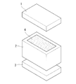
- a molding die in this embodiment is shown in FIG.
- the mold is composed of an upper mold 1, a middle mold 2, and a lower mold 3.
- the middle mold 2 has a cavity 4 inside, and a cavity is formed inside by joining the lower mold 3 and the upper mold 1 to the middle mold 2.
- a sealing member is disposed on the joint surface between the middle mold 2 and the lower mold 3 and the upper mold 1 so that the cavity is sealed when the middle mold 2 and the upper mold 1 and the lower mold 3 are joined. (Illustrated).
- a resin injection line and a suction line (not shown) are connected to the mold so as to communicate with the cavity. The resin injection line and the suction line are arranged so that the resin flows in the thickness direction of the reinforcing fiber substrate when the reinforcing fiber substrate is arranged in the mold.
- FIG. 2 shows an arrangement example of the heating control unit according to the present embodiment.
- the heating control unit includes a lower mold heating control unit 5 and an upper mold heating control unit 6.
- the heating control unit in the present embodiment is a heating plate capable of raising the temperature in a desired range by contacting the mold.
- the heating control unit is not limited to this, and may be embedded in a mold.
- the heating control unit may be arranged so as to heat only the portion containing the reinforcing fiber base material in order to prevent the heat from going around the mold.
- a heating control plate 7 made of a plate (for example, an aluminum alloy) for controlling heat transfer between the heating plate on the side to be heated first (high temperature side) and the mold. It is good to intervene.
- the method for controlling the amount of heat transfer is not limited to the above.
- the lower mold heating control unit 5 includes a lower mold heat source for raising the temperature of the lower mold 3 and can control the heating temperature of the lower mold heat source.
- the heat source for the lower mold may be singular or plural, and the surface facing the cavity direction of the lower mold 3 can be heated substantially uniformly.
- a plurality of heaters are embedded in the lower mold heating control unit 5 at intervals.
- the upper mold heating control unit 6 includes an upper mold heat source for raising the temperature of the upper mold 1 and can control the heating temperature of the upper mold heat source.
- the upper mold heat source may be singular or plural, and the surface of the upper mold 1 facing the cavity direction can be heated substantially uniformly.
- a plurality of heaters are embedded in the upper mold heating control unit 6 at intervals.
- each lower mold heat source may be individually controllable.
- the heating temperature of each upper mold heat source may be individually controllable. Thereby, it is possible to form a temperature difference not only in the thickness direction of the reinforcing fiber base 8 but also in the in-plane direction.
- an intermediate medium is disposed between the mold and the reinforcing fiber substrate 8 when the reinforcing fiber substrate 8 is disposed in the cavity.
- the intermediate medium is between the lower mold 3 and the reinforcing fiber substrate 8, between the upper mold 1 and the reinforcing fiber substrate 8, or between the lower mold 3 and the reinforcing fiber substrate 8, and between the upper mold 1 and the reinforcing fiber substrate 8. It may be disposed both between the substrate 8.
- the type and size of the intermediate medium are selected as appropriate.
- a perforated plate or a perforated film can be used as the intermediate medium.
- FIG. 3 shows an arrangement example of the intermediate medium. For simplification of explanation, description of the lower mold and the upper mold is omitted.
- the intermediate medium 9 is preferably disposed so as to be shifted from each other on both the resin injection part 10 side and the resin discharge part 11 side of the reinforcing fiber base 8.
- the intermediate medium 9 arranged on the resin injection part 10 side has a larger area than the intermediate medium 9 arranged on the resin discharge part 11 side. By doing so, it becomes easy to diffuse the resin injected into the cavity from the resin injection line 12 in the surface direction of the reinforcing fiber base 8.
- the reinforcing fiber substrate used in this embodiment is carbon fiber, glass fiber, aramid fiber, metal fiber, boron fiber, alumina fiber, silicon carbide high-strength synthetic fiber, etc., and carbon fiber is particularly preferable.
- the resin used in this embodiment is a thermosetting resin, such as an epoxy resin.
- a thermosetting resin such as an epoxy resin.
- a phenol resin, polyimide resin, bismaleimide resin, benzoxazine resin, or the like that contains a large amount of volatile components that are difficult to form by conventional RTM can also be used.
- FIG. 4 shows the relationship between time and viscosity / temperature in a thermosetting resin.
- the horizontal axis represents time
- the vertical axis represents viscosity / temperature
- the broken line represents the viscosity profile
- the solid line represents the temperature profile.
- the thermosetting resin once decreases in viscosity by heating, and when a predetermined heating condition is reached, the three-dimensional crosslinking reaction proceeds and the viscosity increases.
- the thermosetting resin is preliminarily heated to be in a low viscosity state that can be impregnated into the reinforcing fiber base material, and then injected into the cavity. Heating conditions are set
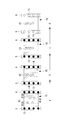
- FIG. 5 is a diagram illustrating the steps of the RTM molding method according to this embodiment.
- the reinforcing fiber base material is disposed in the cavity and then clamped.
- suction is performed from the suction line, and the pressure in the cavity is reduced.
- the mold is heated so that the thermosetting resin used can maintain a low viscosity state for a long time.
- the thermosetting resin is vacuum impregnated and pressurized into the cavity through the resin injection line, and impregnated in the thickness direction of the reinforcing fiber base.
- the resin suction is stopped after impregnating the whole of the reinforcing fiber base material with the thermosetting resin.
- the pressurization of the resin is preferably continued.
- the RTM molding method includes a first temperature raising step and a second temperature raising step in order to cure the thermosetting resin.
- first temperature raising step first, only one of the lower mold and the upper mold is heated at a predetermined rate by the heating control unit.
- the heating control unit In the present embodiment, it is assumed that the lower mold is heated by the lower mold heating control unit to raise the temperature.
- FIG. 6 is a schematic diagram for explaining how the thermosetting resin is cured by the RTM molding method according to this embodiment.
- the description of the mold is omitted for simplification of the drawing.
- the temperature difference is appropriately set according to the type of the thermosetting resin used, the heating profile of the lower mold heat source 13, the thickness of the reinforcing fiber substrate, the fiber density of the reinforcing fiber substrate, and the like.
- the temperature difference is preferably a predetermined value or more.
- the predetermined value is a temperature difference when the heat generated by the lower mold heat source 13 is transmitted to the upper mold heating control side of the reinforcing fiber base 16 including the thermosetting resin.
- the upper die heating control unit 6 After forming the temperature gradient, as the second temperature raising step, the upper die heating control unit 6 starts raising the upper die (C in FIG. 6).
- the upper mold heating control unit 6 controls the temperature of the upper mold heat source 14 so as not to be higher than the temperature of the lower mold heating control unit 5.
- the lower mold and the upper mold are finally heated up to the curing holding temperature of the resin, and the curing holding temperature is held for a predetermined time (D in FIG. 6). Thereafter, heating by each heat source is stopped (E in FIG. 6).
- thermosetting resin on the higher temperature side has a higher viscosity
- thermosetting resin on the lower temperature side has a lower viscosity.
- Bubbles 15 in the thermosetting resin are generated at a low viscosity. Further, the bubbles 15 contained in the thermosetting resin 16 impregnated in the reinforcing fiber base and the volatile components 15 generated by heating for the curing reaction are stabilized as the resin viscosity increases on the lower mold side. It moves to the low viscosity side that can exist. Or it occurs in the low viscosity region.
- the resin shrinkage when the resin is cured moves to the low viscosity side (uncured side).
- the resin shrinkage can be collected on the upper mold side in the mold. Therefore, even a thick plate member having a plate thickness of 10 mm or more can be RTM-molded without generating voids and porosity therein while ensuring plate thickness accuracy.
- the reinforcing fiber base is thick, when the mold is heated by the heating controller, heat is used to heat the resin and the mold is cooled by heat transfer to the atmosphere. Even without a cooling structure, a temperature gradient can be formed in the thickness direction of the reinforcing fiber substrate.
- the mold may be clamped after an intermediate member is disposed between the mold and the reinforcing fiber substrate.
- an intermediate member is disposed between the upper mold and the reinforcing fiber base, voids and porosity can be collected in the intermediate member.
- a 2 inch (50.4 mm) thick reinforcing fiber base made of carbon fiber is placed in the cavity, and impregnated with an epoxy resin from the upper mold side in the thickness direction of the reinforcing fiber base I let you.
- the reinforcing fiber base and the epoxy resin are present in a ratio of 55% by volume and 45% by volume, respectively.
- FIG. 7 shows a temperature profile during RTM molding according to this example.
- the horizontal axis represents time
- the vertical axis represents temperature
- the solid line represents the lower mold temperature profile
- the broken line represents the upper mold temperature profile.
- the temperature of the molds (lower mold, middle mold and upper mold) during resin impregnation was 110 ° C.
- the lower mold was heated and heated by raising the temperature of the lower mold heat source at 0.5 ° C./min by the lower mold heating controller.
- the lower mold was heated to a curing holding temperature of 185 ° C.
- the upper die also reached 185 ° C., and after maintaining the temperature for 2 hours, the heating was stopped.
- the upper mold heat control unit sets the upper mold heat source at a lower temperature rise rate of 0.38 ° C./min.
- the temperature was increased by heating.
- the upper mold was heated to a curing holding temperature of 185 ° C. to maintain the temperature, and then the heating was stopped simultaneously with the lower mold.
- time A the temperature near the lower mold heat source (T1) is raised, the temperature far from the lower mold heat source (T3), and the central area (T2) between T1 and T3 are heated.
- time C when the temperature of the lower mold is raised to 35 ° C. (time C), heat is transferred from the lower mold side to the upper mold side, and the entire reinforcing fiber base impregnated with the resin is heated. At this time, a temperature gradient is formed from T1 to T3, and the temperature has a relationship of t1> t2> t3.
- thermosetting resin exceeds a predetermined heating condition
- the cross-linking reaction proceeds and the viscosity increases, so the viscosity of the resin increases from the portion close to the lower mold heat source. Bubbles, volatile components, and resin shrinkage move to the low viscosity side as the resin temperature rises.
- the temperatures from T1 to T3 during RTM molding were measured.
- Thermocouples were installed on the lower mold side (T1), the central part (T2), and the upper mold side (T3) in the reinforcing fiber base, and the temperature during RTM molding was measured.
- the results are shown in FIG.
- the horizontal axis represents time and the vertical axis represents temperature.
- the temperature rise of the lower mold was started, and the temperature rise of the upper mold was started at 70 minutes.
- the temperature of the lower mold is raised by 35 ° C. and then the upper mold is heated, so that the reinforcing fiber base material including the resin is in the plate thickness direction (T1 to T3) until the upper mold reaches the curing holding temperature. ), It was confirmed that a temperature gradient was always formed.
- FIG. 9 is a schematic diagram for explaining how the thermosetting resin is cured by the RTM molding method according to the comparative example.
- the central part is heated most lastly. Therefore, since bubbles, volatile components, and resin shrinkage are likely to collect in the central portion, voids and porosity derived from the bubbles and volatile components are generated inside after the curing cycle.
Abstract
10mm以上の板厚を持つ厚板部材であっても,板厚精度を確保しつつ,表面及び内部にボイドやポロシティ,樹脂引けのない成形品を成形する方法を提供することを目的とする。RTM成形方法は、2以上に分割された型部材から構成される成形型内に配置された強化繊維基材に熱硬化性樹脂を含浸させた後,成形型を構成するいずれかの型部材を昇温させて,強化繊維基材の一方の側から他方の側へ向けて所定値以上の温度差を有する温度勾配を形成させる第1昇温工程と,第1昇温工程で昇温させた型部材とは異なる他方の型部材を昇温させる第2昇温工程と,を備える。
Description
本発明は,強化繊維基材に熱硬化性樹脂を含浸させてRTM(Resin Transfer Molding)成形するためのRTM成形方法及びRTM成形装置に関するものである。
RTM成形は,一対の成形型の内部に形成されたキャビティに配置した強化繊維基材に熱硬化性樹脂を注入し,該熱硬化性樹脂を加熱硬化させて成形する方法である。RTM成形は,密閉型成形法であるため,非常に高い形状精度が期待できる。
特許文献1に,下型と上型とからなる成形型内に強化繊維布を配置し,成形型内の一端側から熱硬化性樹脂を注入して強化繊維布に含浸させた後,熱硬化性樹脂を加熱及び硬化させて成形するRTM成形装置が記載されている。
従来のRTM成形法では,強化繊維基材の一端側から他端側へ向けて面内方向に熱硬化性樹脂を含浸させる。そのため,厚板部材を成形する場合,熱硬化性樹脂の含浸に多大な時間を要し,且つ,未含浸領域の発生を招く恐れがある。
上記課題の解決方法として,多孔板や穴あきフィルムなどの中間媒体を用いて,強化繊維基材の全面から板厚方向に樹脂を含浸させる方法が提案されている。しかしながら,この方法でも,10mm以上の板厚を持つ厚板部材を成形した場合に,内部にボイド及びポロシティの発生を招くという問題がある。
ボイド及びポロシティは,熱硬化性樹脂に含まれる気泡や,熱硬化性樹脂に含まれる揮発性成分が硬化反応時にガス化することに起因して発生する可能性がある。また,熱硬化性樹脂の硬化収縮などによりひけが発生する可能性もある。
特許文献1では,成形型内に冷却・断熱機構を設け,強化繊維布の面方向に温度傾斜を作り,製品外の樹脂溜り部を一番最後に加熱し,常に熱硬化性樹脂が供給される状態にしておくことで,気泡及び未含浸領域の発生を防ぐことが提案されている。しかしながら,この方法では,熱硬化性樹脂を強化繊維基材の面方向に向けて含浸させているため,10mm以上の板厚を持つ厚板部材を用いた場合に含浸が十分にできず,未含浸領域の発生を招く恐れがある。
特許文献1では,成形型内に冷却管路及び複数の断熱孔を設けているため,治具が複雑になり,制御及びメンテナンスが困難になるという問題がある。
本発明は,このような事情に鑑みてなされたものであって,10mm以上の板厚を持つ厚板部材であっても,板厚精度を確保しつつ,内部にボイドやポロシティのない成形品を成形する方法を提供することを目的とする。
上記課題を解決するために,本発明は,2以上に分割された型部材から構成される成形型内に配置された強化繊維基材に熱硬化性樹脂を含浸させた後,前記成形型を構成するいずれかの型部材を昇温させて,前記強化繊維基材の一方の側から他方の側へ向けて所定値以上の温度差を有する温度勾配を形成させる第1昇温工程と,第1昇温工程で昇温させた型部材とは異なる他方の型部材を昇温させる第2昇温工程と,を備えるRTM成形方法を提供する。
上記発明において,前記第2昇温工程が、前記第1昇温工程の後,第1昇温工程で昇温させた型部材とは異なる他方の型部材の温度が,前記第1昇温工程で昇温させた型部材の温度よりも高くならないよう,前記他方の型部材を昇温させることを含んでも良い。
上記発明において,前記第2昇温工程が、前記第1昇温工程の後,第1昇温工程で昇温させた型部材とは異なる他方の型部材の温度が,前記第1昇温工程で昇温させた型部材の温度よりも高くならないよう,前記他方の型部材を昇温させることを含んでも良い。
熱硬化性樹脂は,加熱することで一旦粘度が低下するが,所定の加熱条件に達すると架橋反応が進み粘度が増加する。熱硬化性樹脂は粘度が低下した状態で強化繊維基材に含浸され,その後更に加熱することで硬化される。上記発明によれば,まずいずれかの成形型を昇温させ,熱硬化性樹脂が含浸された強化繊維基材に温度勾配を形成させる。これによって,成形型を昇温させた側から熱硬化性樹脂の粘性が高くなる一方,成形型を昇温させていない側の熱硬化性樹脂の粘性は低いままとなり,強化繊維基材中で粘度勾配が生じる。熱硬化性樹脂に含まれる気泡や熱硬化性樹脂の硬化反応中に発生する揮発成分は,低粘度側の領域に移動する,もしくは,低粘度側の領域に発生する。また,硬化時の樹脂引けも同様に低粘度側(未硬化側)に集めることができる。そのため,強化繊維基材に所定値以上の温度差の温度勾配を形成させることで,熱硬化性樹脂に含まれる気泡や熱硬化性樹脂の硬化反応中に発生する揮発成分を昇温させていない他方の型部材側へと寄せることができる。すなわち,ボイドやポロシティなどの発生領域を制御することが可能となる。
上記発明の一態様において,前記成形型と前記強化繊維基材との間に中間媒体を配置した後,前記強化繊維基材に前記熱硬化性樹脂を含浸させることが好ましい。
成形型と強化繊維基材との間に中間媒体を配置することで,熱硬化性樹脂を強化繊維基材の面内方向へと拡散させることが可能となる。それにより,熱硬化性樹脂を強化繊維基材の板厚方向に含浸させやすくなるため,未含浸領域の発生を防止することができる。中間媒体を第2昇温工程で昇温される型部材と強化繊維基材との間に配置し,中間媒体側を低温側とすると,熱硬化性樹脂に含まれる気泡や熱硬化性樹脂の硬化反応中に発生する揮発成分,及び,樹脂引けを,中間媒体中に集めることができる。それにより,ボイドやポロシティのない成形品を成形することが可能となる。
本発明は,2以上に分割された型部材から構成される成形型内に配置された強化繊維基材に熱硬化性樹脂を含浸させた後,前記成形型を構成するいずれかの型部材を加熱により昇温させて,前記強化繊維基材の一方の側から他方の側へ向けて所定値以上の温度差を有する温度勾配を形成させる第1加熱制御部と,第1加熱制御部で昇温させた型部材とは異なる他方の型部材の温度が,前記第1昇温工程で昇温させた型部材の温度よりも高くならないよう,前記他方の型部材を昇温させる第2加熱制御部と,を備えるRTM成形装置を提供する。
上記発明によれば,第1加熱制御部を備えることで,成形型の一方を昇温させ,熱硬化性樹脂が含浸された強化繊維基材に温度勾配を形成させる。これによって,成形型を昇温させた側から熱硬化性樹脂の粘性が高くなる一方,成形型を昇温させていない側の熱硬化性樹脂の粘性は低いままとなり,強化繊維基材中に粘度勾配が生じる。熱硬化性樹脂に含まれる気泡や熱硬化性樹脂の硬化反応中に発生する揮発成分は,低粘度側の領域に移動する,もしくは,低粘度側の領域に発生する。また,硬化時の樹脂引けも同様に低粘度側(未硬化側)に集めることができる。よって,ボイドやポロシティなどの発生領域を制御することができる。
第2加熱制御部を備えることで,強化繊維基材に温度勾配が形成された後に,他方の型部材を昇温させ,熱硬化性樹脂に含まれる気泡や熱硬化性樹脂の硬化中に発生する揮発成分を他方の型側へと寄せることが可能となる。
第2加熱制御部を備えることで,強化繊維基材に温度勾配が形成された後に,他方の型部材を昇温させ,熱硬化性樹脂に含まれる気泡や熱硬化性樹脂の硬化中に発生する揮発成分を他方の型側へと寄せることが可能となる。
上記発明の一態様において,前記成形型と前記強化繊維基材との間に中間媒体が配置されることが好ましい。
成形型と強化繊維基材との間に中間媒体を配置することで,熱硬化性樹脂を強化繊維基材の面方向へと拡散させることが可能となる。それにより,熱硬化性樹脂を強化繊維基材の板厚方向に含浸させやすくなるため,未含浸領域の発生を防止することができる。また,中間媒体が第2加熱制御部によって昇温される型部材と強化繊維基材との間に配置された場合,熱硬化性樹脂に含まれる気泡や熱硬化性樹脂の硬化反応中に発生する揮発成分を,中間媒体中に集めることができる。
本発明によれば,10mm以上の板厚を持つ厚板部材であっても,樹脂の未含浸領域を防止し,板厚精度を確保しつつ内部にボイドやポロシティのない成形品を成形することができる。
本発明に係るRTM成形方法及びRTM成形装置は,複合材を成形するためのものであり,次世代民間航空機や超高速輸送機のスパーなどに適用される。
以下に,本発明に係るRTM成形方法及びRTM成形装置の一実施形態について,図面を参照して説明する。
以下に,本発明に係るRTM成形方法及びRTM成形装置の一実施形態について,図面を参照して説明する。
本実施形態に係るRTM成形装置は,成形型及び成形型を昇温させるための加熱制御部を備えている。
成形型は,2以上に分割された型部材から構成されている。本実施形態における成形型を図1に示す。成形型は,上型1,中型2,及び下型3から構成されている。中型2は内部に空洞4を有し,中型2に下型3及び上型1を接合させることで内部にキャビティが形成される。中型2と下型3及び上型1との接合面には,中型2と上型1及び下型3とを接合させた際にキャビティ内が密閉されるようシール部材が配置されている(不図示)。成形型には,キャビティ内に連通するよう樹脂注入ライン及び吸引ライン(不図示)が接続されている。樹脂注入ライン及び吸引ラインは,成形型内に強化繊維基材を配置した場合に,強化繊維基材の厚さ方向に樹脂が流動するよう配置されている。
成形型は,2以上に分割された型部材から構成されている。本実施形態における成形型を図1に示す。成形型は,上型1,中型2,及び下型3から構成されている。中型2は内部に空洞4を有し,中型2に下型3及び上型1を接合させることで内部にキャビティが形成される。中型2と下型3及び上型1との接合面には,中型2と上型1及び下型3とを接合させた際にキャビティ内が密閉されるようシール部材が配置されている(不図示)。成形型には,キャビティ内に連通するよう樹脂注入ライン及び吸引ライン(不図示)が接続されている。樹脂注入ライン及び吸引ラインは,成形型内に強化繊維基材を配置した場合に,強化繊維基材の厚さ方向に樹脂が流動するよう配置されている。
図2に,本実施形態に係る加熱制御部の配置例を示す。加熱制御部は,下型加熱制御部5と上型加熱制御部6とから構成されている。本実施形態における加熱制御部は,成形型に接触して所望の範囲を昇温可能な加熱板とされる。加熱制御部は,これに限定されず,成形型内に埋め込まれても良い。加熱制御部は,金型周囲からの熱の先回りを防ぐために,強化繊維基材の入っている部分だけを暖めるように配置されても良い。熱の伝達量を制御するため,先に昇温させる側(高温側)の加熱板と成形型との間には伝熱を制御するための板(例えば,アルミニウム合金)からなる加熱制御板7を介在させると良い。なお,熱の伝達量を制御する方法は,上記に限定されるものではない。
下型加熱制御部5は,下型3を昇温させるための下型用熱源を含み,該下型用熱源の加熱温度を制御することができる。下型用熱源は,単数または複数であってよく,下型3のキャビティ方向を向く面を略均一に加熱できるものとされる。本実施形態では,複数のヒータが間隔をあけて下型加熱制御部5に埋め込まれている。
上型加熱制御部6は,上型1を昇温させるための上型用熱源を含み,該上型用熱源の加熱温度を制御することができる。上型用熱源は,単数または複数であってよく,上型1のキャビティ方向を向く面を略均一に加熱できるものとされる。本実施形態では,複数のヒータが間隔をあけて上型加熱制御部6に埋め込まれている。
上型加熱制御部6は,上型1を昇温させるための上型用熱源を含み,該上型用熱源の加熱温度を制御することができる。上型用熱源は,単数または複数であってよく,上型1のキャビティ方向を向く面を略均一に加熱できるものとされる。本実施形態では,複数のヒータが間隔をあけて上型加熱制御部6に埋め込まれている。
なお,下型用熱源が複数である場合,各下型用熱源の加熱温度は個別に制御可能な構成とされても良い。上型用熱源が複数である場合,各上型用熱源の加熱温度は個別に制御可能な構成とされても良い。それによって,強化繊維基材8の厚さ方向だけでなく,面内方向にも温度差を形成することが可能となる。
本実施形態に係るRTM成形装置は,キャビティ内に強化繊維基材8を配置したときに,成形型と強化繊維基材8との間に中間媒体が配置されることが好ましい。中間媒体は,下型3と強化繊維基材8との間,上型1と強化繊維基材8との間,または下型3と強化繊維基材8との間及び上型1と強化繊維基材8との間の両方に配置されて良い。中間媒体の種類や大きさは,適宜選択される。例えば,中間媒体として,多孔板や穴あきフィルムなどを用いることができる。図3に中間媒体の配置例を示す。説明の簡略化のため,下型及び上型の記載は省略する。特に,図3において,中間媒体9は,強化繊維基材8の樹脂注入部10側と樹脂排出部11側の両方に,互いに位置をずらして配置すると良い。樹脂注入部10側に配置された中間媒体9は,樹脂排出部11側に配置された中間媒体9よりも面積が大きい。そうすることで,樹脂注入ライン12からキャビティ内に注入された樹脂を強化繊維基材8の面方向に拡散させやすくなる。
次に,本実施形態に係るRTM成形方法について説明する。
本実施形態で用いられる強化繊維基材は,炭素繊維,ガラス繊維,アラミド繊維,金属繊維,ボロン繊維,アルミナ繊維,炭化ケイ素高強度合成繊維等とされ,特に,炭素繊維が好ましい。
本実施形態で用いられる強化繊維基材は,炭素繊維,ガラス繊維,アラミド繊維,金属繊維,ボロン繊維,アルミナ繊維,炭化ケイ素高強度合成繊維等とされ,特に,炭素繊維が好ましい。
本実施形態で用いられる樹脂は,熱硬化性樹脂,例えばエポキシ系樹脂などとされる。本実施形態では,従来RTM成形が難しい揮発成分を多く含むフェノール系樹脂や,ポリイミド系樹脂,ビスマレイミド系樹脂,ベンゾオキサジン樹脂等を使用することもできる。図4に,熱硬化性樹脂における時間と粘度/温度との関係を示す。同図において,横軸が時間,縦軸が粘度/温度,破線が粘度プロファイル,実線が温度プロファイルである。熱硬化性樹脂は,加熱することで一旦粘度が低下し,所定の加熱条件に達すると3次元架橋反応が進み粘度が増加する。熱硬化性樹脂は,予め加熱して,強化繊維基材に含浸可能な程度の低粘度状態とした後にキャビティ内に注入されるものとする。加熱条件は販売元の推奨する条件を基に設定する。
図5に,本実施形態に係るRTM成形方法の工程を説明する図を示す。本実施形態に係るRTM成形方法では,キャビティ内に強化繊維基材を配置した後,型締めする。次に,吸引ラインから吸引し,キャビティ内を減圧する。同時に,使用する熱硬化性樹脂が低粘度状態を長時間維持できるよう成形型を昇温させる。次に,樹脂注入ラインを通してキャビティ内へ熱硬化性樹脂を真空含浸・加圧注入し,強化繊維基材の板厚方向に含浸させる。強化繊維基材の全体に熱硬化性樹脂を含浸させた後,樹脂吸引を停止する。このとき,樹脂の加圧を行い続けると樹脂引けや気泡発生を低減させる効果が得られるので,好ましくは,樹脂の加圧を続けたほうが良い。
次に,強化繊維基材に含浸させた熱硬化性樹脂を硬化させる。本実施形態に係るRTM成形方法は,熱硬化性樹脂を硬化させるために,第1昇温工程と第2昇温工程とを備えている。
第1昇温工程では,まず,加熱制御部によって下型または上型のいずれか一方のみを所定の割合で昇温させる。本実施形態では,下型加熱制御部で下型を加熱して昇温させたものとして説明する。
第1昇温工程では,まず,加熱制御部によって下型または上型のいずれか一方のみを所定の割合で昇温させる。本実施形態では,下型加熱制御部で下型を加熱して昇温させたものとして説明する。
図6に,本実施形態に係るRTM成形方法により熱硬化性樹脂が硬化していく様子を説明する概略図を示す。図6では,図の簡略化のため,成形型の記載を省略した。
下型3を昇温させると,まず,熱硬化性樹脂を含む強化繊維基材16の下型用熱源13に近い部分(下型側)の温度が上がる(図6のA)。このとき,下型用熱源13から離れた部分(上型側)にある熱硬化性樹脂を含む強化繊維基材16は低温(樹脂が低粘度を示す温度)のままである。下型加熱制御部5が昇温されるに従って,熱が上型加熱制御部側へと移動して強化繊維基材の厚さ方向xに温度勾配が形成される(図6のB)。下型加熱制御部5と上型加熱制御部6との間の温度差,すなわち,熱硬化性樹脂を含む強化繊維基材16の下型側と上型側との間に温度差を生じさせる。温度差は,使用した熱硬化性樹脂の種類,下型用熱源13の加熱プロファイル,強化繊維基材の厚さ,強化繊維基材の繊維密度などによって適宜設定する。温度差は所定値以上とすると良い。本実施形態では,所定値を,下型用熱源13で発せられた熱が熱硬化性樹脂を含む強化繊維基材16の上型加熱制御部側まで伝達されたときの温度差とする。
下型3を昇温させると,まず,熱硬化性樹脂を含む強化繊維基材16の下型用熱源13に近い部分(下型側)の温度が上がる(図6のA)。このとき,下型用熱源13から離れた部分(上型側)にある熱硬化性樹脂を含む強化繊維基材16は低温(樹脂が低粘度を示す温度)のままである。下型加熱制御部5が昇温されるに従って,熱が上型加熱制御部側へと移動して強化繊維基材の厚さ方向xに温度勾配が形成される(図6のB)。下型加熱制御部5と上型加熱制御部6との間の温度差,すなわち,熱硬化性樹脂を含む強化繊維基材16の下型側と上型側との間に温度差を生じさせる。温度差は,使用した熱硬化性樹脂の種類,下型用熱源13の加熱プロファイル,強化繊維基材の厚さ,強化繊維基材の繊維密度などによって適宜設定する。温度差は所定値以上とすると良い。本実施形態では,所定値を,下型用熱源13で発せられた熱が熱硬化性樹脂を含む強化繊維基材16の上型加熱制御部側まで伝達されたときの温度差とする。
温度勾配を形成した後に,第2昇温工程として,上型加熱制御部6によって上型の昇温を開始する(図6のC)。上型加熱制御部6は,下型加熱制御部5の温度よりも高くなることがないよう上型用熱源14の温度を制御する。上型加熱制御部6の昇温を開始する際には,熱硬化性樹脂を含む強化繊維基材16の下型側と上型側との間に,すでに所定値以上の温度差を有する温度勾配が存在するため,上型用熱源14の加熱を制御するだけで,上型加熱制御部6の温度を下型加熱制御部5の温度よりも高くならないようにすることができる。
下型及び上型は最終的に樹脂の硬化保持温度まで昇温させ,硬化保持温度を所定時間保持させる(図6のD)。その後,各熱源による加熱を停止する(図6のE)。
本実施形態によれば,熱硬化性樹脂を含浸させた強化繊維基材16の厚さ方向(x)に温度勾配を形成することで,実質的に粘度勾配も形成される。すなわち,温度が高い側の熱硬化性樹脂は粘度が高くなり,温度が低い側の熱硬化性樹脂は粘度が低いままである。熱硬化性樹脂中の気泡15は粘度の低いところで発生する。また,強化繊維基材に含浸させた熱硬化性樹脂16に含まれる気泡15や,硬化反応のための加熱にともない発生する揮発成分15は,下型側における樹脂粘度の増加に伴い,安定して存在できる低粘度側へと移動する。もしくは,低粘度側の領域に発生する。樹脂硬化時の樹脂引けも同様に低粘度側(未硬化側)へ移動する。これにより,気泡や揮発成分,樹脂引けを成形型内の上型側に集めることができる。よって,10mm以上の板厚を持つ厚板部材においても,板厚精度を確保しつつ,内部にボイド及びポロシティを発生させることなくRTM成形することができる。
本実施形態では,強化繊維基材の板厚が厚いため,加熱制御部で成形型を昇温させた場合,樹脂の加熱に熱が使われるとともに,大気への熱伝達で成形型が冷えるため,冷却構造がなくても強化繊維基材の厚さ方向へ温度勾配を形成することができる。
なお,本実施形態では,成形型と強化繊維基材との間に中間部材を配置してから型締めしても良い。上型と強化繊維基材との間に中間部材を配置すると,中間部材にボイドやポロシティを集めることができる。
(実施例)
上記実施形態に従い,炭素繊維からなる厚さ2インチ(50.4mm)の強化繊維基材をキャビティ内に配置し,上型側から強化繊維基材の厚さ方向に向けてエポキシ系樹脂を含浸させた。強化繊維基材及びエポキシ系樹脂は,それぞれ55体積%,45体積%の割合で存在する。
上記実施形態に従い,炭素繊維からなる厚さ2インチ(50.4mm)の強化繊維基材をキャビティ内に配置し,上型側から強化繊維基材の厚さ方向に向けてエポキシ系樹脂を含浸させた。強化繊維基材及びエポキシ系樹脂は,それぞれ55体積%,45体積%の割合で存在する。
図7に,本実施例に係るRTM成形中の温度プロファイルを示す。同図において,横軸が時間,縦軸が温度,実線が下型の温度プロファイル,破線が上型の温度プロファイルである。
樹脂含浸中の成形型(下型,中型及び上型)の温度は110℃とした。含浸終了後,下型加熱制御部により下型用熱源を0.5℃/分で昇温させることで,下型を加熱し昇温させた。下型は硬化保持温度185℃まで昇温させた。上型も185℃に達し,該温度を2時間保持させた後,加熱を停止した。
上型は,型内部に十分温度差ができるよう下型を35℃昇温させた後,上型加熱制御部により上型用熱源を下型よりも低い昇温速度0.38℃/分で昇温させることで加熱し昇温させた。上型は,硬化保持温度185℃まで昇温させて該温度を保持させた後,下型と同時に加熱を停止した。
下型加熱初期(A時点)では,下型用熱源に近い部分(T1)は昇温され,下型用熱源から遠い部分(T3)及び,T1とT3の中央部分(T2)は昇温されていない。本実施例では下型を35℃昇温させた時点(C時点)で下型側から上型側に熱が伝達され,樹脂を含浸させた強化繊維基材全体が加熱される。このとき,T1からT3では温度勾配が形成されており,その温度はt1>t2>t3の関係となる。
熱硬化性樹脂は所定の加熱条件を超えると架橋反応が進み粘性が高くなるため,下型用熱源に近い部分から樹脂の粘度が高くなっていく。気泡や揮発成分,樹脂引けは,樹脂の温度上昇に伴い低粘度側へ移動する。
上型の温度が硬化保持温度に達する(D時点)と,T1からT3での温度が均一化される(t1=t2=t3)。その後,加熱を停止することで樹脂を含む強化繊維基材は冷却される(E時点)。
本実施例について,RTM成形中のT1からT3における温度をそれぞれ測定した。熱電対を強化繊維基材中の下型側(T1),中央部(T2),上型側(T3)に設置してRTM成形中の温度を測定した。結果を図8に示す。同図において横軸が時間,縦軸が温度である。下型の昇温を開始し,上型の昇温を開始したのが70分の時点である。図8によれば,下型を35℃昇温させた後に上型の昇温させることで,上型が硬化保持温度に達するまで,樹脂を含む強化繊維基材の板厚方向(T1からT3)には,常に温度勾配が形成されていることが確認された。
実施例でRTM成形した成形品の断面を光学顕微鏡で観察したところ,成形品の内部にボイドやポロシティの発生はみられなかった。
(比較例)
上型を,実施例の下型と同じ温度プロファイルで昇温させた以外は,実施例と同様とした。比較例として成形した成形品の内部には,ボイドやポロシティが発生していた。
図9に,比較例に係るRTM成形方法により熱硬化性樹脂が硬化していく様子を説明する概略図を示す。比較例では,下型加熱制御部5と上型加熱制御部6とを同時に昇温させているため,中央部が一番最後に加熱されることになる。よって,気泡や揮発成分,樹脂引けが中央部に集まりやすくなるため,硬化サイクル終了後,気泡や揮発成分に由来するボイドやポロシティが内部に発生する。
上型を,実施例の下型と同じ温度プロファイルで昇温させた以外は,実施例と同様とした。比較例として成形した成形品の内部には,ボイドやポロシティが発生していた。
図9に,比較例に係るRTM成形方法により熱硬化性樹脂が硬化していく様子を説明する概略図を示す。比較例では,下型加熱制御部5と上型加熱制御部6とを同時に昇温させているため,中央部が一番最後に加熱されることになる。よって,気泡や揮発成分,樹脂引けが中央部に集まりやすくなるため,硬化サイクル終了後,気泡や揮発成分に由来するボイドやポロシティが内部に発生する。
1 上型
2 中型
3 下型
4 空洞
5 下型加熱制御部
6 上型加熱制御部
7 加熱制御板
8 強化繊維基材
9 中間媒体
10 樹脂注入部
11 樹脂排出部
12 樹脂注入ライン
13 下型用熱源
14 上型用熱源
15 気泡,揮発成分
16 熱硬化樹脂を含む強化繊維基材
2 中型
3 下型
4 空洞
5 下型加熱制御部
6 上型加熱制御部
7 加熱制御板
8 強化繊維基材
9 中間媒体
10 樹脂注入部
11 樹脂排出部
12 樹脂注入ライン
13 下型用熱源
14 上型用熱源
15 気泡,揮発成分
16 熱硬化樹脂を含む強化繊維基材
Claims (5)
- 2以上に分割された型部材から構成される成形型内に配置された強化繊維基材に熱硬化性樹脂を含浸させた後,前記成形型を構成するいずれかの型部材を昇温させて,前記強化繊維基材の一方の側から他方の側へ向けて所定値以上の温度差を有する温度勾配を形成させる第1昇温工程と,
第1昇温工程で昇温させた型部材とは異なる他方の型部材を昇温させる第2昇温工程と,
を備えるRTM成形方法。 - 前記第2昇温工程が、前記第1昇温工程の後,第1昇温工程で昇温させた型部材とは異なる他方の型部材の温度が,前記第1昇温工程で昇温させた型部材の温度よりも高くならないよう,前記他方の型部材を昇温させることを含む請求項1に記載のRTM成形方法。
- 前記成形型と前記強化繊維基材との間に中間媒体を配置した後,前記強化繊維基材に前記熱硬化性樹脂を含浸させる請求項1または請求項2に記載のRTM成形方法。
- 2以上に分割された型部材から構成される成形型内に配置された強化繊維基材に熱硬化性樹脂を含浸させた後,前記成形型を構成するいずれかの型部材を加熱により昇温させて,前記強化繊維基材の一方の側から他方の側へ向けて所定値以上の温度差を有する温度勾配を形成させる第1加熱制御部と,
第1加熱制御部で昇温させた型部材とは異なる他方の型部材の温度が,前記第1昇温工程で昇温させた型部材の温度よりも高くならないよう,前記他方の型部材を昇温させる第2加熱制御部と,
を備えるRTM成形装置。 - 前記成形型と前記強化繊維基材との間に中間媒体が配置された請求項4に記載のRTM成形装置。
Priority Applications (3)
| Application Number | Priority Date | Filing Date | Title |
|---|---|---|---|
| US14/117,497 US20140070452A1 (en) | 2011-05-16 | 2012-03-15 | Rtm method and rtm apparatus |
| CA2836015A CA2836015C (en) | 2011-05-16 | 2012-03-15 | Resin transfer molding method and resin transfer molding apparatus |
| EP20120785535 EP2711154A4 (en) | 2011-05-16 | 2012-03-15 | Artificial resin transfer molding method and resin transfer molding device |
Applications Claiming Priority (2)
| Application Number | Priority Date | Filing Date | Title |
|---|---|---|---|
| JP2011109670A JP5791365B2 (ja) | 2011-05-16 | 2011-05-16 | Rtm成形方法及びrtm成形装置 |
| JP2011-109670 | 2011-05-16 |
Publications (1)
| Publication Number | Publication Date |
|---|---|
| WO2012157327A1 true WO2012157327A1 (ja) | 2012-11-22 |
Family
ID=47176669
Family Applications (1)
| Application Number | Title | Priority Date | Filing Date |
|---|---|---|---|
| PCT/JP2012/056696 WO2012157327A1 (ja) | 2011-05-16 | 2012-03-15 | Rtm成形方法及びrtm成形装置 |
Country Status (5)
| Country | Link |
|---|---|
| US (1) | US20140070452A1 (ja) |
| EP (1) | EP2711154A4 (ja) |
| JP (1) | JP5791365B2 (ja) |
| CA (1) | CA2836015C (ja) |
| WO (1) | WO2012157327A1 (ja) |
Cited By (1)
| Publication number | Priority date | Publication date | Assignee | Title |
|---|---|---|---|---|
| JP2018140595A (ja) * | 2017-02-28 | 2018-09-13 | 株式会社Subaru | 繊維強化複合材料の製造方法 |
Families Citing this family (3)
| Publication number | Priority date | Publication date | Assignee | Title |
|---|---|---|---|---|
| US20170157804A1 (en) * | 2014-01-17 | 2017-06-08 | Toray Industries, Inc. | Coated fiber-reinforced resin molded article and manufacturing method of the same |
| ES2898785T3 (es) * | 2016-02-23 | 2022-03-08 | Toray Industries | Procedimiento de producción de material compuesto reforzado con fibra |
| JP6715226B2 (ja) | 2017-10-25 | 2020-07-01 | 株式会社Subaru | 複合材成形治具及び複合材成形方法 |
Citations (4)
| Publication number | Priority date | Publication date | Assignee | Title |
|---|---|---|---|---|
| JPH04144723A (ja) * | 1990-10-08 | 1992-05-19 | Mitsubishi Kasei Corp | 繊維強化樹脂成形体の製造方法 |
| JP2003025346A (ja) * | 2001-07-16 | 2003-01-29 | Toray Ind Inc | Rtm成形方法 |
| JP3421101B2 (ja) | 1993-12-09 | 2003-06-30 | 富士重工業株式会社 | 複合材の成形装置 |
| JP2005246902A (ja) * | 2004-03-08 | 2005-09-15 | Toray Ind Inc | Rtm成形方法 |
Family Cites Families (5)
| Publication number | Priority date | Publication date | Assignee | Title |
|---|---|---|---|---|
| US4784814A (en) * | 1985-07-11 | 1988-11-15 | Ciba-Geigy Corporation | Pressure reaction injection molding process for making molded bodies of thermosets optionally containing filler and/or reinforcing material |
| US5052906A (en) * | 1989-03-30 | 1991-10-01 | Seemann Composite Systems, Inc. | Plastic transfer molding apparatus for the production of fiber reinforced plastic structures |
| JP2781354B2 (ja) * | 1994-12-28 | 1998-07-30 | 日本碍子株式会社 | 加熱冷却機構付きセグメントおよびそれを用いた金型 |
| FR2740382B1 (fr) * | 1995-10-25 | 1997-12-05 | Snecma | Procede de moulage de pieces allongees a haute resistance en composite fibre-resine |
| DE102008014657B4 (de) * | 2008-03-17 | 2015-08-20 | Airbus Defence and Space GmbH | Verfahren zur Herstellung von Faserverbundbauteilen |
-
2011
- 2011-05-16 JP JP2011109670A patent/JP5791365B2/ja active Active
-
2012
- 2012-03-15 EP EP20120785535 patent/EP2711154A4/en not_active Withdrawn
- 2012-03-15 CA CA2836015A patent/CA2836015C/en not_active Expired - Fee Related
- 2012-03-15 WO PCT/JP2012/056696 patent/WO2012157327A1/ja active Application Filing
- 2012-03-15 US US14/117,497 patent/US20140070452A1/en not_active Abandoned
Patent Citations (4)
| Publication number | Priority date | Publication date | Assignee | Title |
|---|---|---|---|---|
| JPH04144723A (ja) * | 1990-10-08 | 1992-05-19 | Mitsubishi Kasei Corp | 繊維強化樹脂成形体の製造方法 |
| JP3421101B2 (ja) | 1993-12-09 | 2003-06-30 | 富士重工業株式会社 | 複合材の成形装置 |
| JP2003025346A (ja) * | 2001-07-16 | 2003-01-29 | Toray Ind Inc | Rtm成形方法 |
| JP2005246902A (ja) * | 2004-03-08 | 2005-09-15 | Toray Ind Inc | Rtm成形方法 |
Non-Patent Citations (1)
| Title |
|---|
| See also references of EP2711154A4 |
Cited By (2)
| Publication number | Priority date | Publication date | Assignee | Title |
|---|---|---|---|---|
| JP2018140595A (ja) * | 2017-02-28 | 2018-09-13 | 株式会社Subaru | 繊維強化複合材料の製造方法 |
| US11167452B2 (en) | 2017-02-28 | 2021-11-09 | Subaru Corporation | Method of manufacturing fiber-reinforced composite material |
Also Published As
| Publication number | Publication date |
|---|---|
| US20140070452A1 (en) | 2014-03-13 |
| EP2711154A1 (en) | 2014-03-26 |
| CA2836015A1 (en) | 2012-11-22 |
| JP2012240231A (ja) | 2012-12-10 |
| CA2836015C (en) | 2016-10-04 |
| EP2711154A4 (en) | 2015-03-04 |
| JP5791365B2 (ja) | 2015-10-07 |
Similar Documents
| Publication | Publication Date | Title |
|---|---|---|
| CA2662476C (en) | Forming-molding tool and process for producing preforms and fiber reinforced plastics with the tool | |
| RU2635623C2 (ru) | Способ формирования формованной заготовки | |
| RU2697451C2 (ru) | Способ изготовления композитного изделия | |
| JP6557972B2 (ja) | 繊維強化プラスチックの製造方法および製造装置 | |
| CN103192536B (zh) | 纤维增强树脂基复合材料的微波高压间歇固化法及模具 | |
| CN106457697B (zh) | 用于制造设有单向纤维稀松布的smc构件的方法 | |
| US20070120288A1 (en) | System, method, and apparatus for production-worthy, low cost composite tool fabrication | |
| EP2842711B1 (en) | Apparatus and method for producing a composite material aircraft component | |
| CN103687707A (zh) | 纤维强化树脂和轻量化芯的复合材料、制造该复合材料的方法以及装置 | |
| WO2000054949A2 (en) | Heated tooling apparatus and method for processing composite and plastic material | |
| WO2012157327A1 (ja) | Rtm成形方法及びrtm成形装置 | |
| EP3702155B1 (en) | Method for preparing a composite product and composite product | |
| CN109986799B (zh) | 用于制造纤维预制件的方法和设备 | |
| JP6384213B2 (ja) | 複合材料の製造方法、複合材料の製造装置 | |
| CN109397724B (zh) | 一种耐高温复合材料及其高温热膨胀成型方法 | |
| KR101447136B1 (ko) | 섬유 강화 복합재의 성형방법 | |
| US20220281184A1 (en) | Preform heating | |
| JP6750735B2 (ja) | 複合材料の成形方法および複合材料の成形装置 | |
| JP2016135575A (ja) | 複合材料の成形方法および成形装置 | |
| JPWO2017061146A1 (ja) | 繊維強化複合部材の成形装置 | |
| JP2020526414A (ja) | 製織された繊維プリフォームに樹脂を注入することによって部品を製造するための方法および装置 | |
| US20240025135A1 (en) | Method for producing composite molded body | |
| RU2742301C1 (ru) | Способ изготовления модельной оснастки для формования изделий из полимерных композиционных материалов (варианты) | |
| WO2020246622A1 (ja) | 熱可塑性繊維強化樹脂成形品の製造方法 | |
| JP2018039130A (ja) | 複合材料の成形方法および複合材料の成形装置 |
Legal Events
| Date | Code | Title | Description |
|---|---|---|---|
| 121 | Ep: the epo has been informed by wipo that ep was designated in this application |
Ref document number: 12785535 Country of ref document: EP Kind code of ref document: A1 |
|
| ENP | Entry into the national phase |
Ref document number: 2836015 Country of ref document: CA |
|
| WWE | Wipo information: entry into national phase |
Ref document number: 14117497 Country of ref document: US |
|
| WWE | Wipo information: entry into national phase |
Ref document number: 2012785535 Country of ref document: EP |
|
| NENP | Non-entry into the national phase |
Ref country code: DE |