WO2012157236A1 - Regenerative water softening device - Google Patents
Regenerative water softening device Download PDFInfo
- Publication number
- WO2012157236A1 WO2012157236A1 PCT/JP2012/003105 JP2012003105W WO2012157236A1 WO 2012157236 A1 WO2012157236 A1 WO 2012157236A1 JP 2012003105 W JP2012003105 W JP 2012003105W WO 2012157236 A1 WO2012157236 A1 WO 2012157236A1
- Authority
- WO
- WIPO (PCT)
- Prior art keywords
- water
- ion exchange
- exchange membrane
- inlet
- outlet
- Prior art date
Links
Images


Classifications
-
- C—CHEMISTRY; METALLURGY
- C02—TREATMENT OF WATER, WASTE WATER, SEWAGE, OR SLUDGE
- C02F—TREATMENT OF WATER, WASTE WATER, SEWAGE, OR SLUDGE
- C02F1/00—Treatment of water, waste water, or sewage
- C02F1/46—Treatment of water, waste water, or sewage by electrochemical methods
- C02F1/469—Treatment of water, waste water, or sewage by electrochemical methods by electrochemical separation, e.g. by electro-osmosis, electrodialysis, electrophoresis
- C02F1/4693—Treatment of water, waste water, or sewage by electrochemical methods by electrochemical separation, e.g. by electro-osmosis, electrodialysis, electrophoresis electrodialysis
-
- B—PERFORMING OPERATIONS; TRANSPORTING
- B01—PHYSICAL OR CHEMICAL PROCESSES OR APPARATUS IN GENERAL
- B01J—CHEMICAL OR PHYSICAL PROCESSES, e.g. CATALYSIS OR COLLOID CHEMISTRY; THEIR RELEVANT APPARATUS
- B01J47/00—Ion-exchange processes in general; Apparatus therefor
- B01J47/02—Column or bed processes
- B01J47/04—Mixed-bed processes
-
- B—PERFORMING OPERATIONS; TRANSPORTING
- B01—PHYSICAL OR CHEMICAL PROCESSES OR APPARATUS IN GENERAL
- B01J—CHEMICAL OR PHYSICAL PROCESSES, e.g. CATALYSIS OR COLLOID CHEMISTRY; THEIR RELEVANT APPARATUS
- B01J47/00—Ion-exchange processes in general; Apparatus therefor
- B01J47/02—Column or bed processes
- B01J47/06—Column or bed processes during which the ion-exchange material is subjected to a physical treatment, e.g. heat, electric current, irradiation or vibration
- B01J47/08—Column or bed processes during which the ion-exchange material is subjected to a physical treatment, e.g. heat, electric current, irradiation or vibration subjected to a direct electric current
-
- B—PERFORMING OPERATIONS; TRANSPORTING
- B01—PHYSICAL OR CHEMICAL PROCESSES OR APPARATUS IN GENERAL
- B01J—CHEMICAL OR PHYSICAL PROCESSES, e.g. CATALYSIS OR COLLOID CHEMISTRY; THEIR RELEVANT APPARATUS
- B01J47/00—Ion-exchange processes in general; Apparatus therefor
- B01J47/12—Ion-exchange processes in general; Apparatus therefor characterised by the use of ion-exchange material in the form of ribbons, filaments, fibres or sheets, e.g. membranes
-
- B—PERFORMING OPERATIONS; TRANSPORTING
- B01—PHYSICAL OR CHEMICAL PROCESSES OR APPARATUS IN GENERAL
- B01J—CHEMICAL OR PHYSICAL PROCESSES, e.g. CATALYSIS OR COLLOID CHEMISTRY; THEIR RELEVANT APPARATUS
- B01J49/00—Regeneration or reactivation of ion-exchangers; Apparatus therefor
- B01J49/20—Regeneration or reactivation of ion-exchangers; Apparatus therefor of membranes
-
- B—PERFORMING OPERATIONS; TRANSPORTING
- B01—PHYSICAL OR CHEMICAL PROCESSES OR APPARATUS IN GENERAL
- B01J—CHEMICAL OR PHYSICAL PROCESSES, e.g. CATALYSIS OR COLLOID CHEMISTRY; THEIR RELEVANT APPARATUS
- B01J49/00—Regeneration or reactivation of ion-exchangers; Apparatus therefor
- B01J49/30—Electrical regeneration
-
- B—PERFORMING OPERATIONS; TRANSPORTING
- B01—PHYSICAL OR CHEMICAL PROCESSES OR APPARATUS IN GENERAL
- B01J—CHEMICAL OR PHYSICAL PROCESSES, e.g. CATALYSIS OR COLLOID CHEMISTRY; THEIR RELEVANT APPARATUS
- B01J49/00—Regeneration or reactivation of ion-exchangers; Apparatus therefor
- B01J49/75—Regeneration or reactivation of ion-exchangers; Apparatus therefor of water softeners
-
- B—PERFORMING OPERATIONS; TRANSPORTING
- B01—PHYSICAL OR CHEMICAL PROCESSES OR APPARATUS IN GENERAL
- B01D—SEPARATION
- B01D61/00—Processes of separation using semi-permeable membranes, e.g. dialysis, osmosis or ultrafiltration; Apparatus, accessories or auxiliary operations specially adapted therefor
- B01D61/42—Electrodialysis; Electro-osmosis ; Electro-ultrafiltration; Membrane capacitive deionization
- B01D61/44—Ion-selective electrodialysis
- B01D61/445—Ion-selective electrodialysis with bipolar membranes; Water splitting
-
- C—CHEMISTRY; METALLURGY
- C02—TREATMENT OF WATER, WASTE WATER, SEWAGE, OR SLUDGE
- C02F—TREATMENT OF WATER, WASTE WATER, SEWAGE, OR SLUDGE
- C02F2201/00—Apparatus for treatment of water, waste water or sewage
- C02F2201/46—Apparatus for electrochemical processes
- C02F2201/461—Electrolysis apparatus
- C02F2201/46105—Details relating to the electrolytic devices
- C02F2201/4611—Fluid flow
-
- C—CHEMISTRY; METALLURGY
- C02—TREATMENT OF WATER, WASTE WATER, SEWAGE, OR SLUDGE
- C02F—TREATMENT OF WATER, WASTE WATER, SEWAGE, OR SLUDGE
- C02F2201/00—Apparatus for treatment of water, waste water or sewage
- C02F2201/46—Apparatus for electrochemical processes
- C02F2201/461—Electrolysis apparatus
- C02F2201/46105—Details relating to the electrolytic devices
- C02F2201/46115—Electrolytic cell with membranes or diaphragms
-
- C—CHEMISTRY; METALLURGY
- C02—TREATMENT OF WATER, WASTE WATER, SEWAGE, OR SLUDGE
- C02F—TREATMENT OF WATER, WASTE WATER, SEWAGE, OR SLUDGE
- C02F2201/00—Apparatus for treatment of water, waste water or sewage
- C02F2201/46—Apparatus for electrochemical processes
- C02F2201/461—Electrolysis apparatus
- C02F2201/46105—Details relating to the electrolytic devices
- C02F2201/4618—Supplying or removing reactants or electrolyte
-
- C—CHEMISTRY; METALLURGY
- C02—TREATMENT OF WATER, WASTE WATER, SEWAGE, OR SLUDGE
- C02F—TREATMENT OF WATER, WASTE WATER, SEWAGE, OR SLUDGE
- C02F2209/00—Controlling or monitoring parameters in water treatment
- C02F2209/03—Pressure
-
- C—CHEMISTRY; METALLURGY
- C02—TREATMENT OF WATER, WASTE WATER, SEWAGE, OR SLUDGE
- C02F—TREATMENT OF WATER, WASTE WATER, SEWAGE, OR SLUDGE
- C02F2209/00—Controlling or monitoring parameters in water treatment
- C02F2209/40—Liquid flow rate
-
- C—CHEMISTRY; METALLURGY
- C02—TREATMENT OF WATER, WASTE WATER, SEWAGE, OR SLUDGE
- C02F—TREATMENT OF WATER, WASTE WATER, SEWAGE, OR SLUDGE
- C02F2303/00—Specific treatment goals
- C02F2303/16—Regeneration of sorbents, filters
-
- C—CHEMISTRY; METALLURGY
- C02—TREATMENT OF WATER, WASTE WATER, SEWAGE, OR SLUDGE
- C02F—TREATMENT OF WATER, WASTE WATER, SEWAGE, OR SLUDGE
- C02F2303/00—Specific treatment goals
- C02F2303/22—Eliminating or preventing deposits, scale removal, scale prevention
Definitions
- the present invention relates to a regenerative water softener, and more particularly to a regenerative water softener that softens water by removing cations of hardness components such as calcium and magnesium.
- This water-splitting ion exchange membrane includes, for example, a cation exchange surface and an anion exchange surface.
- the water-splitting ion exchange membrane is disposed between the first electrode and the second electrode so that the cation exchange surface faces the first electrode.
- a voltage is applied so that the first electrode becomes an anode and the second electrode becomes a cathode.
- the cation in the solution is adsorbed on the cation exchange surface of the water-splitting ion exchange membrane, the cation is removed from the solution, and the solution is softened.
- a voltage is applied so that the first electrode becomes a cathode and the second electrode becomes an anode.
- Water decomposes into hydrogen ions and hydroxide ions at the interface between the cation exchange surface and the anion exchange surface of the water-splitting ion exchange membrane. Hydrogen ions are adsorbed on the cation exchange surface, and the cations adsorbed on the cation exchange surface are released. In this way, ion exchange is performed, and the water-splitting ion exchange membrane is regenerated.
- the present invention has been made to solve such a problem, and an object of the present invention is to provide a regenerative water softening device that suppresses power consumption compared to the prior art.
- a regenerative water softening device includes a cathode and an anode, a cation exchange surface on one surface, an anion exchange surface on the other surface, and the anion exchange surface.
- the regeneration pressure between the second inlet and the second outlet at the same flow rate as that of the processing water, the differential pressure of the processing water between the first inlet and the first outlet Greater than water differential pressure.
- the present invention has an effect that it is possible to suppress power consumption in the regenerative water softening device.
- FIG. 2 is a side view schematically showing a water-splitting porous ion exchange membrane used in the regenerative water softening device of FIG. 1.
- A) is the cross-sectional view which showed typically the regeneration-type water softening apparatus which concerns on Embodiment 2 of this invention
- (b) shows typically the regeneration-type water softening apparatus of (a).
- FIG. It is the perspective view which showed typically the regenerative water softening evaluation apparatus which concerns on Embodiment 3 of this invention.
- FIG. 6 is a cross-sectional view schematically showing the regenerative water softening device in FIG. 5. It is a top view which shows the spacer used for the regeneration-type water softening apparatus of FIG. It is a conceptual diagram showing the flow of the water for a process in the regenerative water softening process of FIG. It is a conceptual diagram showing the flow of the water for reproduction
- FIG. 1 It is sectional drawing which showed typically the 1st water softening evaluation apparatus used for Example 1.
- FIG. It is a graph which shows the relationship between calcium removal capability (water softening capability) and flowing water time. It is a graph which shows the relationship between calcium desorption capability (regeneration capability of an ion exchange membrane) and flowing water time.
- a regenerative water softening device includes a cathode and an anode, a cation exchange surface on one side, an anion exchange surface on the other side, and the anion exchange
- a differential pressure between the first inlet and the first outlet, the differential pressure of the processing water between the first inlet and the second outlet at the same flow rate as the processing water. Greater than the differential pressure of water for regeneration.
- a straight line connecting the first inlet and the first outlet of the treatment water and the second of the reclaimed water may be provided so that a straight line connecting the inlet and the second outlet is perpendicular.
- the differential pressure of the treatment water generated between the first inlet and the first outlet can be set larger than the differential pressure of the regeneration water generated between the second inlet and the second outlet.
- the water-splitting ion exchange membrane connects the first inlet and the first outlet of the treatment water. It may be provided perpendicular to a straight line and parallel to a straight line connecting the second inlet and the second outlet of the water for regeneration.
- the treatment water when the treatment water is softened, the treatment water flows perpendicular to the water-splitting ion exchange membrane. For this reason, the contact probability between the hardness component ions in the water for treatment and the water-splitting ion exchange membrane is increased, the hardness component ions are efficiently adsorbed, and the water softening efficiency is improved.
- the water for regeneration flows parallel to the water-splitting ion exchange membrane. For this reason, the desorbed hardness component ions do not pass through the inside of the membrane, but quickly flow along the surface of the water-splitting ion exchange by the regeneration water. Therefore, the hardness component ions are prevented from adsorbing again on the ion exchange membrane, and the regeneration efficiency is increased.
- the water-splitting ion exchange membrane has a rectangular shape, and its long side is the treatment water.
- the short side may be provided in parallel to a straight line connecting the second inlet and the second outlet of the water for regeneration.
- the water for regeneration flows along the short side of the water-splitting ion exchange membrane.
- the desorbed hardness component ions are prevented from flowing over the surface of the water-splitting ion-exchange membrane in a short time by the regeneration water and adsorbing to the ion-exchange membrane again.
- the regeneration efficiency of the water-splitting ion exchange membrane is improved.
- the water-splitting ion exchange membrane in the third regenerative water softening device, may be formed of a porous material.
- the processing water when the processing water is softened, the processing water that flows perpendicularly to the water-splitting ion exchange membrane passes through the water-splitting ion exchange membrane.
- the treatment water enters the inside of the water-splitting ion exchange membrane, so that the contact area between the hardness component ions in the treatment water and the water-splitting ion exchange membrane further increases, and the hardness component ions are efficiently adsorbed and softened. Efficiency is improved.
- a regenerative water softening device is the fifth regenerative water softening device according to the fifth regenerative water softening device, comprising a non-water-permeable sealing material covering the periphery of a laminate in which a plurality of the water-splitting ion exchange membranes are laminated. Further, it may be provided.
- the treatment water when the treatment water is softened, the treatment water does not escape between the laminate of the water-splitting ion exchange membrane and the casing by the non-water-permeable sealing material, and is perpendicular to the water-splitting ion exchange membrane. Flowing. For this reason, hardness component ions in the treatment water are efficiently adsorbed on the water-splitting ion exchange membrane, and the efficiency of softening the treatment water is increased.
- a regenerative water softening device is the fifth or sixth regenerative water softening device, wherein the plurality of water-splitting ion exchange membranes are laminated and the first inlet side is the above-mentioned
- a diffusion layer provided between the electrodes and having a greater water resistance than the water-splitting ion exchange membrane may be further provided.
- the treatment water when the treatment water is softened, the treatment water is diffused in the direction perpendicular to the water-splitting ion exchange membrane by the diffusion layer. For this reason, when the treatment water passes through a wide range of the water-splitting ion exchange membrane, the contact area between the hardness component ions and the water-splitting ion exchange membrane further increases, and the water softening efficiency of the treatment water is improved.
- the regenerative water softening device is the spacer member provided in the sixth or seventh regenerative water softening device so that the adjacent water-splitting ion exchange membranes are sandwiched between the laminates. May be further provided.
- the regeneration water passes through the space formed by the spacer member.
- the water for regeneration flows smoothly in parallel with the water-splitting ion exchange membrane, and the desorbed hardness component ions are quickly discharged. For this reason, it is suppressed that hardness component ion re-adsorbs to a water-splitting ion-exchange membrane, and a water-splitting ion-exchange membrane is reproduced
- the sealing material penetrates in the thickness direction, and the second inlet and the second outlet of the water for regeneration are used.
- the openings may be opposed to the spacer member.
- the second inlet and the second outlet of the regeneration water face the spacer member through the opening. For this reason, at the time of regeneration of the water-splitting ion exchange membrane, the regeneration water flows from the second inlet into the space of the spacer member through the opening, and flows out to the second outlet through the opening. Thus, the regeneration water flows smoothly and the ion exchange membrane can be efficiently regenerated.
- the sealing material can prevent the flow of the water for regeneration from being disturbed, and can be prevented from flowing into the gap between the laminate of the water-decomposing ion-exchange membrane for treatment water and the casing.
- the openings may be arranged one-to-one on the spacer member.
- the regeneration water that has flowed in from the second inlet flows into the space of the spacer member that faces the opening portion on a one-to-one basis without branching.
- regeneration which passed the space of the spacer member flows out from a 2nd exit through the opening part which faces on one-on-one without branching. For this reason, the water for reproduction
- a regenerative water softening device is the regenerative water softening device according to any one of the first to tenth aspects, wherein when the treatment water is passed, the first inlet and the first outlet of the treatment water. Is opened, and the second inlet and the second outlet of the regeneration water are closed, and when the regeneration water is passed, the second inlet and the second outlet of the regeneration water are opened, and the first inlet and the first of the treatment water are opened.
- the exit may be closed.
- the processing water when the processing water is softened, the processing water flows from the first inlet to the first outlet without flowing out from the second inlet and the second outlet. Further, when the water-splitting ion exchange membrane is regenerated, the regeneration water flows from the second inlet to the second outlet without flowing out from the first inlet and the first outlet. Water softening treatment and regeneration treatment are performed more efficiently.
- a direction parallel to the cation exchange surface and the anion exchange surface of the water-splitting porous ion exchange membrane is referred to as a vertical direction
- a direction orthogonal to the vertical direction is referred to as a horizontal direction.
- treatment water water to be softened
- regeneration water water used for regenerating the ion exchange membrane
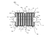
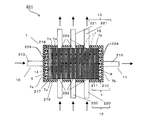
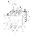
- FIG. 1 is a cross-sectional view schematically showing a regenerative water softening device according to Embodiment 1 of the present invention.
- FIG. 2A is a plan view schematically showing the main surface of the cathode.
- FIG. 2B is a plan view schematically showing the main surface of the anode.
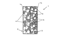
- FIG. 3 is a side view schematically showing a water-splitting porous ion exchange membrane.
- a regenerative water softening device (hereinafter referred to as “water softening device”) 201 is formed by a water-splitting porous ion exchange membrane (hereinafter referred to as “ion exchange membrane”) 1. It is an apparatus that removes cations of hardness components such as ions and magnesium ions (hereinafter referred to as “hardness component ions”) from the water for treatment, and softens the water for treatment.
- the water softening device 201 includes electrodes 8 and 9, an ion exchange membrane, and a casing 7 that houses the electrode and the ion exchange membrane 1.
- each electrode 8, 9 is a substantially rectangular flat plate, and has connection portions 8 a, 9 a and a large number of openings 224.
- the opening 224 penetrates the main surface of each electrode 8, 9.
- the size and number of the openings 224 are set so as not to obstruct the flow of processing water passing through the openings 224.
- Each electrode 8 and 9 is comprised with plate
- board materials such as a metal
- the metal titanium having corrosion resistance and mechanical durability is used.
- the protective layer platinum coating or the like is raised, and the thickness of the protective layer is, for example, 0.2 ⁇ m to 0.5 ⁇ m.
- the ion exchange membrane 1 has a cation exchange surface 1a on one surface and an anion exchange surface 1b on the other surface.
- the ion exchange membrane 1 is laminated between the cathode 8 and the anode 9 such that the anion exchange surface 1 b faces the anode 9 and the cation exchange surface 1 a faces the cathode 8.
- the ion exchange membrane 1 is formed by superposing and joining a cation exchange membrane 2 and an anion exchange membrane 3 in the thickness direction. For this reason, the cation exchange surface 1 a is formed on the surface of the cation exchange membrane 2, and the anion exchange surface 1 b is formed on the surface of the anion exchange membrane 3.
- the cation exchange membrane 2 is formed of a sintered body solidified by heating a mixture of the cation exchange resin particles 4 and the thermoplastic resin particles 5 in the vicinity of the melting point of the thermoplastic resin particles 5. For this reason, the cation exchange resin particles 4 are fixed in the matrix of the thermoplastic resin particles 5 so that a void is formed between the cation exchange resin particles 4 and the thermoplastic resin particles 5.
- the anion exchange membrane 3 is formed of a sintered body that is solidified by heating a mixture of the anion exchange resin particles 6 and the thermoplastic resin particles 5 in the vicinity of the melting point of the thermoplastic resin particles 5. For this reason, the anion exchange resin particles 6 are fixed in the matrix of the thermoplastic resin particles 5 so that a void is formed between the anion exchange resin particles 6 and the thermoplastic resin particles 5.
- the thermoplastic resin particles 5 are formed of, for example, a thermoplastic resin such as a polyolefin resin such as polyethylene and polypropylene, an ethylene-propylene copolymer, an ethylene-vinyl acetate copolymer, and an ethylene-acrylic acid copolymer.
- a thermoplastic resin such as a polyolefin resin such as polyethylene and polypropylene, an ethylene-propylene copolymer, an ethylene-vinyl acetate copolymer, and an ethylene-acrylic acid copolymer.
- the particle diameter of the thermoplastic resin particles 5 is set to several tens to several hundreds ⁇ m, for example. However, as the particle diameter of the thermoplastic resin particles 5 is smaller, the rate at which hardness component ions are adsorbed to the ion exchange membrane 1 is increased, and the efficiency of removing the hardness component ions is improved. However, the smaller the particle size of the thermoplastic resin particles 5, the greater the pressure loss when the treatment water passes through the ion exchange membrane 1. For this reason, the particle diameter of the thermoplastic resin particles 5 is set in consideration of the removal efficiency of hardness component ions and the pressure loss.
- the cation exchange resin particles 4 are formed of, for example, a strongly acidic cation exchange resin having an exchange group —SO 3 H.
- the anion exchange resin particles 6 are formed of, for example, a strongly basic ion exchange resin having an exchange group —NR 3 OH.
- the cation exchange resin particles 4 can also be formed from a weakly acidic cation exchange resin having an exchange group —RCOOH.
- the anion exchange resin particles 6 can be formed from a weakly basic ion exchange resin having —NR 2 .
- the content of the cation exchange resin particles 4 in the cation exchange membrane 2 and the content of the anion exchange resin particles 6 in the anion exchange membrane 3 are 10 to 60 wt% with respect to the weight of each ion exchange membrane 2 and 3. Thus, it is preferably 30 to 50 wt%.
- the content of each ion-exchange resin particle 4 or 6 is 60% or more, the amount of the thermoplastic resin particle 5 is reduced with respect to each ion-exchange resin particle 4 or 6. Is difficult to fix with the thermoplastic resin particles 5.
- the content of each ion exchange resin particle 4 or 6 is 10% or less, the capacity for exchanging ions in the unit volume of each ion exchange membrane 2 or 3 becomes small.
- each ion exchange membrane 2, 3 which leads to an increase in size and cost of the water softening device 201.
- the content of each of the ion exchange resin particles 4 and 6 is 30 to 50 wt%, the ion exchange capacity of the ion exchange membrane 1 can be maintained, and the ion exchange membrane 1 can be used stably over a long period of time. Can do.
- the casing 7 has a rectangular parallelepiped shape, and includes first to fourth side surfaces 7a to 7d, a first end surface, a second end surface, and a hollow portion surrounded by these.
- the second side surface 7b faces the first side surface 7a
- the fourth side surface 7d faces the third side surface 7c.
- the first and second side surfaces 7a and 7b are shorter than the third and fourth side surfaces 7c and 7d. For this reason, the space
- the casing 7 has a first inlet 10 and a first outlet 11 for water for treatment, and a second inlet 12 and a second outlet 13 for water for regeneration.
- the first inlet 10 and the second inlet 12 are each connected to piping (not shown) supplied from a water source such as a water pipe.
- the first outlet 11 is a faucet (not shown) that discharges the water for softening treatment, a water heater that uses the water for softening treatment, a hot water heating system, a washing machine, a water purification system, or the like (Not shown).
- the second outlet 13 is connected to a path (not shown) for discharging the regeneration water used for the regeneration process of the ion exchange membrane 1.
- a first inlet 10 into which the processing water flows is provided on the first side surface 7a, and a first outlet 11 through which the processing water flows out is provided on the second side surface 7b.
- a second inlet 12 through which the regeneration water flows is provided on the third side surface 7c, and a second outlet 13 through which the regeneration water flows out is provided on the fourth side surface 7d.
- the first inlet 10 and the first outlet are set so that the straight line connecting the first inlet 10 and the first outlet 11 of the treatment water and the straight line connecting the second inlet 12 and the second outlet 13 of the regeneration water are perpendicular to each other. 11, a second inlet 12 and a second outlet 13 are provided.
- the respective inlets 10 and 12 and the respective outlets 11 and 13 penetrate the respective side surfaces 7a to 7d.
- Solenoid valves 16a to 16d are provided at the first inlet 10, the first outlet 11, the second inlet 12, and the second outlet 13, respectively.
- a straight line connecting the first inlet 10 and the first outlet 11 of the processing water is formed by connecting the center of the first inlet 10 and the center of the first outlet 11.
- a straight line connecting the second inlet 12 and the second outlet 13 of the water for regeneration is formed by connecting the center of the second inlet 12 and the center of the second outlet 13.
- the first inlet 10 and the first outlet 11 are set so that the straight line connecting the first inlet 10 and the first outlet 11 of the treatment water and the straight line connecting the second inlet 12 and the second outlet 13 of the regeneration water are perpendicular to each other.
- a second inlet 12 and a second outlet 13 are provided, and the overall flow of treatment water from the first inlet 10 to the first outlet 11 is the overall flow of regeneration water from the second inlet 12 to the second outlet 13. Be perpendicular to the flow.
- the anode 9, the cathode 8, and one or more, in this embodiment, a laminate of seven ion exchange membranes 1 are accommodated.
- the anode 9, the cathode 8, and the ion exchange membrane 1 are arranged in parallel so that the cation exchange membrane 2 faces the cathode 8 and the anion exchange membrane 3 faces the anode 9.
- the ion exchange membrane 1 is provided perpendicular to a straight line connecting the first inlet 10 and the first outlet 11. For this reason, the flow path 14 of the processing water flowing in from the first inlet 10 and flowing out from the first outlet 11 extends in a direction orthogonal to the ion exchange membrane 1.
- the ion exchange membrane 1 Since the ion exchange membrane 1 is formed in substantially the same size as the longitudinal section of the hollow portion of the casing 7, the ion exchange membrane 1 is arranged so as to block the flow path 14 for the processing water.
- the ion exchange membrane 1 is provided in parallel to a straight line connecting the second inlet 12 and the second outlet 13. For this reason, the flow path 15 for regenerating water flowing in from the second inlet 12 and flowing out from the second outlet 13 extends along the ion exchange membrane 1.
- a gap is provided between the anode 9, the cathode 8, and the ion exchange membrane 1. This gap becomes a flow path 15 for water for regeneration.
- the treatment water channel 14 formed between the first inlet 10 and the first outlet 11 is longer than the regeneration water channel 15 formed between the second inlet 12 and the second outlet 13. For this reason, the differential pressure of the treatment water generated between the first inlet 10 and the first outlet 11 is greater than the differential pressure of the regeneration water generated between the second inlet 12 and the second outlet 13 at the same flow rate as the treatment water. growing.
- the casing 7 is further provided with an opening (not shown).
- the connecting portion 8a of the cathode 8 and the connecting portion 9a of the anode 9 protrude from the opening.
- a sealing material (not shown) is filled between the opening and each connection portion 8a, 9a, and the watertight performance of the casing 7 is maintained.
- Each connecting portion 8a, 9a is connected to a power source (not shown) by an electric wire (not shown), and a switch (not shown) is interposed in the electric wire.
- the treatment water flows from the first inlet 10, passes through the opening 224 of the cathode 8, and further passes through the ion exchange membrane 1. At this time, hardness component ions contained in the water for treatment are adsorbed on the cation exchange resin particles 4 of the cation exchange membrane 2. As a result, hardness component ions are removed from the treatment water, and the treatment water becomes soft water and is discharged from the first outlet 11.
- the flow rate of the treatment water is reduced by the drag. Moreover, since the treatment water receives resistance by the ion exchange membrane 1 when the treatment water passes through the ion exchange membrane 1, the flow rate of the treatment water further decreases. As a result, the time during which the treatment water stays in the casing 7 becomes long, and the treatment water comes into contact with the cation exchange resin particles 4 for a long time. Further, the treatment water passes through the cation exchange membrane 2 so that the treatment water also comes into contact with the cation exchange resin particles 4 inside the cation exchange membrane 2. Therefore, the hardness component ions in the water for treatment are adsorbed in contact with a large number of cation exchange resin particles 4 for a long time, thereby improving the adsorption efficiency of the hardness component ions.
- the adsorption efficiency of hardness component ions is high. As a result, it is not necessary to pass the hardness component ions through the ion exchange membrane 1 by applying a voltage to the electrodes 8 and 9 and moving the hardness component ions by electrophoresis. Therefore, electric power is not consumed in the water softening step, and overall power consumption is suppressed.
- the regeneration water in the casing 7 is electrolyzed at the interface between the cation exchange membrane 2 and the anion exchange membrane 3, and hydrogen ions are generated in the cation exchange membrane 2, and hydroxide ions Is generated in the anion exchange membrane 3.
- the electrolyzed hydrogen ions are replaced with the hardness component ions adsorbed on the cation exchange resin particles 4 of the cation exchange membrane 2.
- hardness component ions are removed from the cation exchange membrane 2, and the ion exchange membrane 1 is regenerated.
- the hardness component ions desorbed from the ion exchange membrane 1 are discharged from the second outlet 13 along with the flow through the regeneration water channel 15.
- the regeneration water channel 15 is parallel to the ion exchange membrane 1
- hardness component ions passing through the regeneration water channel 15 move along the surface of the ion exchange membrane 1.
- the hardness component is prevented from reattaching to the ion exchange membrane 1 without almost entering the inside of the ion exchange membrane 1, and the ion exchange membrane 1 is efficiently regenerated.
- hydrogen ions that replace hardness component ions attached to the ion exchange membrane 1 are generated at the interface between the cation exchange membrane 2 and the anion exchange membrane 3. Thereby, hardness component ions are removed from the inside of the ion exchange membrane 1 by hydrogen ions, and the entire ion exchange membrane 1 is regenerated.
- the regeneration water passage 15 is shorter than the treated raw water passage 14, the decrease in the regeneration water flow rate due to drag is small.
- the regeneration water passes along the surface of the ion exchange membrane 1, the resistance received from the ion exchange membrane 1 is small, and a decrease in the flow rate of the regeneration water is suppressed.
- the time for the regeneration water to stay in the casing 7 is short, and the time for the regeneration water to contact the cation exchange resin particles 4 is shortened.
- the regeneration water is along the surface of the cation exchange membrane 2, the cation exchange resin particles 4 inside the cation exchange membrane 2 and the treatment water hardly come into contact with each other. Therefore, the time and range in which the hardness component ions in the water for regeneration come into contact with the cation exchange resin particles 4 are short, and the hardness component ions are prevented from being re-adsorbed on the ion exchange membrane 1.
- the first inlet 10 and the first outlet 11 are opened, and the second inlet 12 and the second outlet 13 are closed.
- the treatment water flowing in from the first inlet 10 does not flow out of the second inlet 12 and the second outlet 13 but flows out of the first outlet 11.
- the process water flow path 14 extended from the 1st inlet 10 to the 1st outlet 11 is formed, and a water softening process is performed efficiently.
- the second inlet 12 and the second outlet 13 are opened, and the first inlet 10 and the first outlet 11 are closed.
- the regeneration water that has flowed in from the second inlet 12 does not flow out of the first inlet 10 and the first outlet 11 but flows out of the second outlet 13.
- the regeneration water flow path 15 extending from the second inlet 12 to the second outlet 13 is formed, and the regeneration process is performed efficiently.
- the ion exchange membrane 1 is provided perpendicular to the straight line connecting the first inlet 10 and the first outlet 11, that is, the processing water flow path 14.
- the ion exchange membrane 1 is provided in parallel to the straight line connecting the first inlet 10 and the first outlet 11, that is, to the treatment water flow path 14.
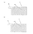
- FIG. 4A is a cross-sectional view schematically showing a water softening device according to Embodiment 2 of the present invention.
- FIG.4 (b) is a longitudinal cross-sectional view which shows typically the water softening apparatus of Fig.4 (a).
- the cathode 8 and the anode 9 are provided in parallel to the first end surface 7e and the second end surface 7f of the casing 7.
- the ion exchange membrane 1 is provided between the cathode 8 and the anode 9 such that the anion exchange membrane 3 faces the anode 9 and the cation exchange membrane 2 faces the cathode 8.
- the ion exchange membrane 1 has a rectangular shape including a long side 1a and a short side 1b. Each length of the long side 1a and the short side 1b is set based on the contact probability of hardness component ions to the ion exchange membrane 1.
- the ion exchange membrane 1 has a long side 1 a parallel to a straight line connecting the first inlet 10 and the first outlet 11, and a short side 1 a corresponding to a straight line connecting the second inlet 12 and the second outlet 13. Are provided in parallel. For this reason, the anode 9, the cathode 8, and one or more, in this embodiment, for example, two ion exchange membranes 1 are stacked in parallel with a gap therebetween.
- a treatment water channel 14 and a regeneration water channel 15 are formed in the gaps between the electrodes 8 and 9 and the ion exchange membrane 1 and in the gaps between adjacent ion exchange membranes 1.
- the treatment water flows along the ion exchange membrane 1, the treatment water does not enter the inside of the ion exchange membrane 1 compared to the case where the treatment water passes through the ion exchange membrane 1.
- the treatment water flow path 14 is long, the treatment water is in contact with the cation exchange resin particles 4 in the ion exchange membrane 1 for a long time. Therefore, the hardness component ions in the water for treatment are adsorbed by contacting with the cation exchange resin particles 4 for a long time, thereby improving the adsorption efficiency of the hardness component ions.
- the regeneration water flows along the ion exchange membrane 1, it is possible to prevent the desorbed hardness component ions from entering the ion exchange membrane 1 and reattaching.
- the regeneration water channel 15 is shorter than the treated raw water channel 14, the time for which the regeneration water is in contact with the cation exchange resin particles 4 is short, so that the hardness component ions are regenerated on the downstream side of the ion exchange membrane 1. Adsorption is prevented.
- hydrogen ions are generated at the interface between the cation exchange membrane 2 and the anion exchange membrane 3, the hardness component ions are totally removed from the inside of the ion exchange membrane 1, and the entire ion exchange membrane 1 is regenerated.
- the first inlet 10, the first outlet 11, the second inlet 12, and the second outlet 13 are provided one by one.
- a plurality of first inlets 10, first outlets 11, second inlets 12, and second outlets 13 are provided in the water softening device 201 of the third embodiment.
- the water softening device 201 of the third embodiment further includes a diffusion layer 218, a spacer member 217, and a sealing material 219.
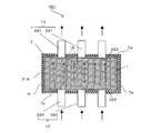
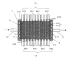
- FIG. 5 is a perspective view schematically showing a water softening device according to Embodiment 3 of the present invention.
- FIG. 6 is a longitudinal sectional view showing the water softening device cut along the line BB shown in FIG.
- FIG. 7 is a cross-sectional view showing the water softening device 201 cut along the line CC shown in FIG.
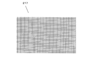
- FIG. 8 is a plan view schematically showing a spacer member used in the water softening device of FIG.
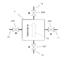
- FIG. 9 is a conceptual diagram showing the flow of processing water in the water softening step.
- FIG. 10 is a conceptual diagram showing the flow of water for regeneration in the regeneration process.
- a first inlet 10, a first outlet 11, a second inlet 12, and a second outlet 13 are provided in the casing 7.
- the first inlet 10 for example, three pipes 213 are connected to the first side surface 7a. These pipes 213 are collected into one main pipe (not shown) provided with an electromagnetic valve 225 (FIGS. 9 and 10).
- the first outlet 11 for example, three pipes 215 (FIG. 6) are connected to the second side surface 7b. These pipes 215 are collected into one main pipe (not shown) provided with an electromagnetic valve 226 (FIGS. 9 and 10).
- the second inlet 12 for example, nine pipes 220 are connected to the third side surface 7c.
- the casing 7 accommodates therein a pair of electrodes 8 and 9 and a laminated body in which a plurality of, in this embodiment, 10 ion exchange membranes 1 are laminated.
- the ion exchange membrane 1 is disposed between the anode 9 and the cathode 8 such that the cation exchange membrane 210 faces in parallel with the cathode 8 and the anion exchange membrane 211 faces in parallel with the anode 9.
- the ion exchange membrane 1 is formed by joining the cation exchange membrane 210 and the anion exchange membrane 211 so as to overlap each other in the thickness direction.
- the cation exchange membrane 210 is the same as the cation exchange membrane 2 shown in FIG. 3, and the anion exchange membrane 211 is the same as the anion exchange membrane 3 shown in FIG.
- the spacer member 217 is provided so as to sandwich the ion exchange membrane 1 in order to secure a flow path for flowing regeneration water between the adjacent ion exchange membranes 1 in the laminate.
- the spacer member 217 may be disposed between the anode 9 and the ion exchange membrane 1 and between the cathode 8 and the ion exchange membrane 1.
- As the spacer member 217 a plate-like body having a large number of through holes, for example, a mesh-like mesh sheet shown in FIG. 8 is used, and the size thereof is set to the same size as the surface of the ion exchange membrane 1, for example. .
- the spacer member 217 is formed of, for example, a fluororesin ETFE having water resistance and mechanical durability.
- the diffusion layer 218 is a layer that diffuses the processing water flowing from the first inlet 10 in a direction perpendicular to the processing water flow path 14.
- the diffusion layer 218 is formed from a resin having water resistance and mechanical durability, such as polyethylene and high-density polyethylene.
- the diffusion layer 218 is formed of, for example, a porous sheet that has a greater water resistance than the ion exchange membrane 1.
- the diffusion layer 218 is provided between the laminate of the ion exchange membrane 1 and the electrode on the first inlet 10 side, in this embodiment, the anode 9.
- the diffusion layer 218 is disposed perpendicular to the treatment water flow path 14 and parallel to the ion exchange membrane 1.
- the sealing material 219 is a non-water-permeable member that covers the periphery of the laminate of the ion exchange membrane 1 as shown in FIGS. 6 and 7.
- the sealing material 219 is filled between the end surface of the ion exchange membrane 1 and the inner surfaces 7c, 7d, 7e, and 7f of the casing 7, and prevents treatment water from passing therethrough.
- the end surface of the ion exchange membrane 1 is a surface that is perpendicular to the bonding surface of the ion exchange membrane 1 and is arranged in parallel with the treatment water flow path 14.
- the sealing material 219 is formed of, for example, a silicone resin having water permeability and water resistance.
- the sealing material 219 has a plurality of openings 222 and 223 on the side surfaces 7c and 7d of the casing 7, respectively.
- the plurality of openings 222 and 223 penetrate in the thickness direction of the sealing material 219.
- the number of the openings 222 is arranged so that the number thereof matches the number of the pipes 220 of the second inlet 12, and the positions thereof face the pipes 220 and the spacer member 217. For this reason, the regeneration water that has flowed from the pipe 220 flows into the regeneration water flow path 15 formed in the spacer member 217.
- the number of openings 223 is arranged so that the number thereof matches the number of pipes 221 of the second outlet 13 and the positions thereof face the pipes 221 and the spacer member 217, respectively. Therefore, the regeneration water that has passed through the regeneration water passage 15 in the spacer member 217 is discharged from the pipe 221.
- the treatment water flows uniformly from the entire diffusion layer 218 to the entire surface of the ion exchange membrane 1.
- the treatment water passes through the through holes of the spacer member 217 and the ion exchange membrane 1.
- the treatment water has a large resistance to pass through the inside of the ion exchange membrane 1, but the treatment water has passed through the ion exchange membrane 1 because the periphery of the laminate of the ion exchange membrane 1 is covered with the sealing material 219. pass.
- hardness component ions contained in the treatment water are adsorbed on the cation exchange membrane 210 of the ion exchange membrane 1, and the treatment water is softened.
- the treatment water passes through the laminated body of the ion exchange membrane 1 and then flows out through the opening 224 of the cathode 8 to the pipe 215 of the first outlet 11.
- the regeneration water flows along the ion exchange membrane 1 through the regeneration water channel 15 in the spacer member 217.
- a voltage of 100 V to 300 V is applied to each electrode 8, 9, so that the water for regeneration is hydrogen ion and water at the interface between the cation exchange membrane 210 and the anion exchange membrane 211 in the ion exchange membrane 1.
- the hydrogen ions are replaced with hardness component ions adsorbed on the cation exchange membrane 210, and the ion exchange membrane 1 is regenerated.
- the hardness component ions are desorbed from the cation exchange membrane 210 and discharged from the pipe 221 of the second outlet 13 through the opening 223 along with the regeneration water.
- the non-water-permeable sealing material 219 prevents the treatment water from flowing between the casing 7 and the ion exchange membrane 1. Thereby, it is suppressed that the quantity of the process water which passes the ion exchange membrane 1 reduces. Therefore, the contact probability between the cation exchange resin particles 4 of the cation exchange membrane 210 of the ion exchange membrane 1 and the hardness component ions is increased, and the hardness component ions are efficiently adsorbed to the cation exchange resin particles 4, so that The efficiency of water softening can be increased.
- the opening portions 222 and 223 of the sealing material 219 face the pipes 220 and 221 and the spacer member 217, respectively. For this reason, the regeneration water that has flowed in from the pipe 220 passes smoothly through the opening 222 into the regeneration water flow path 15 in the spacer member 217. Therefore, the hardness component ions desorbed from the ion exchange membrane 1 are almost parallel to the ion exchange membrane 1 while spreading along the surface of the ion exchange membrane 1 without almost entering the inside of the ion exchange membrane 1 by the regeneration water. Flowing. Therefore, hardness component ions can be prevented from adsorbing to the cation exchange resin particles 4, and the regeneration efficiency is increased.
- the spacer member 217 is disposed between the ion exchange membranes 1 adjacent to each other in the laminate, and forms a regeneration water flow path 15 extending in parallel with the ion exchange membrane 1. For this reason, the regeneration water flows smoothly in parallel with the ion exchange membrane 1, and the area and time for contacting the hardness component ions desorbed in the regeneration water with the ion exchange membrane 1 are reduced. Therefore, resorption of hardness component ions to the ion exchange membrane 1 is suppressed, and the regeneration efficiency of the ion exchange membrane 1 is improved.
- the diffusion layer 218 is disposed between the electrode 9 on the first inlet 10 side and the laminate of the ion exchange membrane 1.
- the treatment water flowing from the first inlet 10 is directed to the ion exchange membrane 1 while spreading in a direction perpendicular to the treatment water flow path 14. Therefore, the treatment water passes through the ion exchange membrane 1 as a whole, and hardness component ions contained in the treatment water are adsorbed in a wide range of the ion exchange membrane 1. Accordingly, the water softening performance of the treatment water is further improved.
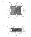
- FIG. 11 is a perspective view schematically showing a water softening device according to Embodiment 4 of the present invention.
- 12 is a longitudinal sectional view showing the water softening device cut along the line DD shown in FIG.
- the number of the pipe 220 at the second inlet 12, the pipe 221 at the second outlet 13, the spacer member 217, and the openings 222 and 223 of the sealing material 219 are equal.
- the opening 222 of the sealing material 219 faces the piping 220 and the spacer member 217 on a one-to-one basis
- the opening 223 faces the piping 221 and the spacer member 217 on a one-to-one basis.
- the pipe 220 at the second inlet 12 and the pipe 221 at the second outlet 13 penetrate the sealing material 219 through the openings 222 and 223.
- the pipe 220 at the second inlet 12 and the pipe 221 at the second outlet 13 are in contact with the space in which the spacer member 217 is disposed.
- the water for regeneration flows from the pipe 220 of the second inlet 12 through the opening 222 into the space member facing it. Then, the regeneration water flows into the regeneration water flow path 15 in the space member facing the opening 222 without branching to the regeneration water flow path 15 in the plurality of space members. Further, the regeneration water that has passed through the regeneration water flow path 15 flows out from the pipe 221 through the opening 223 that faces the space member. For this reason, the regeneration water passes smoothly through the regeneration water flow path 15 along the ion exchange membrane 1. As a result, the hardness component ions contained in the water for regeneration are reduced in time and range in contact with the ion exchange membrane 1 and are prevented from being re-adsorbed on the ion exchange membrane 1. As a result, the regeneration efficiency of the ion exchange membrane 1 by the regeneration water in the entire water softening device 201 is further improved.
- a DC voltage of, for example, 100 V to 300 V is applied between the electrodes 9 and 8 in the regeneration process.
- the value of the DC voltage is appropriately set according to the number of ion exchange membranes 1 disposed in the casing 7 and the hardness of the water for treatment.
- the electrodes 8 and 9 having the openings 224 are used, but electrodes having no openings may be used.
- the treatment water passes around the electrodes 8 and 9 in the first, third, and fourth embodiments, and passes between the electrodes 8 and 9 in the second embodiment.
- the ion exchange membrane 1 was formed by joining the cation exchange membrane 2 and the anion exchange membrane 3.
- an ion exchange membrane can also be formed by arranging the cation exchange membrane 2 and the anion exchange membrane 3 so as not to be joined.
- the cation exchange surface 1a is the surface of the cation exchange membrane 2.
- the anion exchange surface 1b was formed on the surface of the anion exchange membrane 3.
- the formation method of the cation exchange surface 1a and the anion exchange surface 1b is not limited to this.
- the cation exchange surface 1a may be formed on one surface of one ion exchange membrane, and the anion exchange surface 1b may be formed on the other surface.
- the water softening device 201 of the first, third, and fourth embodiments since the water for treatment is passed in the direction perpendicular to the ion exchange membrane 1 in the water softening step, the water-splitting porous ion exchange membrane having water permeability is used. 1 was used for the ion exchange membrane 1. However, when treatment water flows parallel to the surface of the ion exchange membrane 1 as in the second embodiment, the ion exchange membrane 1 having water permeability may not be used.
- both the diffusion layer 218 and the sealing material 219 are provided.
- only the sealing material 219 may be provided.
- At least one of the spacer member 217, the diffusion layer 218, and the sealing material 219 may be further provided.
- a spacer member 217 may be further provided.
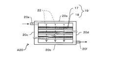
- FIG. 13 is a cross-sectional view schematically showing the first water softening evaluation device.
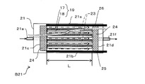
- FIG. 14 is a cross-sectional view schematically showing the second water softening evaluation apparatus.
- Example 1 Using the first water softening evaluation device A20 of FIG. 13 and the second water softening evaluation device B21 of FIG. 14, the water softening ability (hardness component ion removal ability) according to the direction of water flow with respect to the ion exchange membrane 1 was evaluated.
- a cation exchange membrane 17 was prepared using cation exchange resin particles of 100 to 150 ⁇ m and polyethylene resin particles as thermoplastic resin particles of several tens to several hundreds of ⁇ m.
- An anion exchange membrane 18 was prepared using anion exchange resin particles of 100 to 150 ⁇ m and polyethylene resin particles as thermoplastic resin particles of several tens to several 100 ⁇ m.
- the thickness of each ion exchange membrane 17, 18 is 1 mm.
- These cation exchange membrane 17 and anion exchange membrane 18 were bonded together to form an ion exchange membrane 19.
- the ion exchange membrane 19 had a thickness of 2 mm, a short side of 4 cm, and a long side of 10 cm.
- the 1st water softening evaluation apparatus A20 is an apparatus which evaluates water softening by the decreasing rate of the hardness component ion contained in water, when water is flowed perpendicularly with respect to the ion exchange membrane 1.
- the first water softening evaluation apparatus A20 includes first and second long sides 20a and 20b, first and second short sides 20c and 20d, an inlet 20e, and an outlet 20f.
- the inflow port 20e is disposed on the first short side 20c on the first long side 20a side
- the outflow port 20f is disposed on the second short side 20d on the second long side 20b side.
- the water flow path 22 in the first water softening evaluation device A20 is perpendicular to the long sides 20a and 20b from the first long side 20a side to the second long side 20b side, and each short side. The flow is parallel to 20c and 20d.
- the first water softening evaluation apparatus A20 a plurality of laminated bodies in which, for example, seven ion exchange membranes 19 are laminated are accommodated in this embodiment.
- the water flow distance of the flow path 22, that is, the length between the first long side 20a and the second long side 20b is about 14 mm, for example.
- Each ion exchange membrane 19 is arranged such that the cation exchange membrane 17 faces the first long side 20a in parallel and the anion exchange membrane 18 faces the second long side 20b in parallel.
- the ion exchange membrane 19 has a long side parallel to the long sides 20a and 20b, and is provided at an equal interval. For this reason, the ion exchange membrane 19 is arranged perpendicular to the flow of water.
- the long side of the ion exchange membrane 1 is between the first short side 20c and the second short side 20d. Fit in between.
- the gap may be filled with an adhesive, a leak-proof packing, or the like so that no gap is generated between the ion exchange membrane 19 and each of the short sides 20c and 20d.
- an adhesive or the like is disposed so that the flow of water from the inlet 20e to the outlet 20f is not hindered.
- the 2nd water softening evaluation apparatus B21 is an apparatus which evaluates water softening by the decreasing rate of the hardness component ion contained in water, when water is flowed in parallel with respect to the ion exchange membrane 1.
- the second water softening evaluation apparatus B21 includes first and second long sides 21a and 21b, first and second short sides 21c and 21d, an inlet 21e, and an outlet 21f.
- the inflow port 21e is disposed on the first short side 21c
- the outflow port 21f is disposed on the second short side 21d.
- the inflow port 21e and the outflow port 21f are disposed so as to face each other between the first long side 21a and the second long side 21b.
- the water flow path 23 in the second water softening evaluation apparatus B21 is parallel to the long sides 20a and 20b from the first short side 21c side to the second short side 21d side, and each short side 20c. , 20d.
- the water flow distance of the flow path 23, that is, the length between the first short side 21c and the second short side 21d is, for example, 10 cm.
- each ion exchange membrane 19 is arranged such that the cation exchange membrane 17 faces the first long side 21a in parallel and the anion exchange membrane 18 faces the second long side 21b in parallel.
- each ion exchange membrane 19 has a long side parallel to the long sides 21a and 21b and is provided at equal intervals. For this reason, the ion exchange membrane 19 is arranged in parallel to the flow of water.
- the long side of the ion exchange membrane 19 is between the first short side 21c and the second short side 21d. Fit in between.
- the gap may be filled with an adhesive, a leak-proof packing, or the like so that no gap is generated between the ion exchange membrane 19 and each of the short sides 21c and 21d.
- an adhesive or the like is arranged so that the flow of water from the inlet 21e to the outlet 21f is not hindered.
- the rectifying plate 24 is provided between the first short side 21c and the laminate of the ion exchange membrane 19 and the second short side 21d. And the laminated body of the ion exchange membranes 19.
- the concentration of hardness component ions of water flowing in from the inlets 20e and 21e was adjusted to about 190 ppm in terms of calcium carbonate (CaCO3).
- This water is, for example, 0.42 L / min. Flowed in from the inlets 20e and 21e. And water passes the flow paths 22 and 23, and flows out from the outflow ports 20f and 21f. Calcium ions contained in water at the outlets 20f and 21f were measured. And the calcium removal capacity
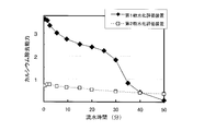
- FIG. 15 is a graph showing the relationship between calcium removal ability (water softening ability) and running time.
- the vertical axis represents the calcium removal ability in which the difference between the hardness component ion concentration at the inlets 20e and 21e and the hardness component ion concentration at the outlets 20f and 21f is normalized by a predetermined value.
- the calcium removal ability (water softening ability) of the first water softening evaluation device A20 is about 3 to 4 times as large as the calcium removal ability (water softening ability) of the second water softening evaluation device B21. From this result, when water passes perpendicularly to the ion exchange membrane 19 as in the first water softening evaluation apparatus A20, the water exchange membrane 19 efficiently adsorbs calcium ions contained in water, and the water is softened. It can be seen that
- Example 2 Regeneration capability of ion exchange membrane 1 of water softening device 201 (ability to desorb hardness component ions from ion exchange membrane 1) according to the length of the flow path using second water softening evaluation device B21 of FIG. was evaluated.
- an anode 25 and a cathode 26 are accommodated in the second water softening evaluation apparatus B21.
- a laminate of the ion exchange membrane 19 is sandwiched between the anode 25 and the cathode 26 such that the anode 25 faces the anion exchange membrane 18 in parallel and the cathode 26 faces the cation exchange membrane 17 in parallel.
- a voltage of 100 V is applied to the anode 25 and the cathode 26.
- about 50 ppm of water in terms of calcium carbonate (CaCO3) is 0.42 L / min.
- the concentration of calcium ions contained in the water at the outlet 21f was measured.
- the calcium desorption capacity in the channel 23 having a length of 10 cm (regeneration capacity of the ion exchange membrane 1).
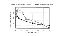
- FIG. 16 is a graph showing the relationship between calcium desorption capacity (regeneration capacity of the ion exchange membrane 1) and running water time.
- the vertical axis indicates the calcium desorption ability obtained by standardizing the difference between the hardness component ion concentration at the inlet 21e and the hardness component ion concentration at the outlet 21f with a predetermined value.
- the calcium desorption ability (regeneration ability of the ion exchange membrane 1) when the length of the flow path 23 is 10 cm is smaller than that when the length of the flow path 23 is 6 cm.
- the water softening device of the present invention is useful as a water softening device or the like that suppresses power consumption as compared with the prior art.
Abstract
This water softening device (201) is provided with: a negative electrode (8) and a positive electrode (9); at least one water-splitting ion exchange membrane (1) that has a positive ion exchange surface (1a) on one surface, has a negative ion exchange surface (1b) on the other surface, and is layered between the negative electrode and the positive electrode in a manner so that the negative ion exchange surface faces the positive electrode and the positive ion exchange surface faces the negative electrode; and a casing (7) that houses the negative electrode, the positive electrode, and the at least one water-splitting ion exchange membrane. The casing has: a first entrance (10) and a first exit (11) that are respectively the entrance and exit for water for processing; and a second entrance (12) and second exit (13) that are respectively the entrance and exit for water for regeneration. The differential pressure of the water for processing between the first entrance and the first exit is greater than the differential pressure of the water for regeneration between the second entrance and the second exit at the same flow rate as that of the water for processing.
Description
本発明は、再生式軟水化装置に関し、特に、カルシウムやマグネシウムなどの硬度成分の陽イオンを除去することにより水を軟水化する再生式軟水化装置に関する。
The present invention relates to a regenerative water softener, and more particularly to a regenerative water softener that softens water by removing cations of hardness components such as calcium and magnesium.
従来、薬剤を使用しない再生式の軟水化技術として、電気分解および水分解イオン交換膜を用いて硬度成分の陽イオンを除去し、かつ水分解イオン交換膜を再生することができる技術がある(たとえば、特許文献1参照)。
Conventionally, as a regenerative water softening technique that does not use a chemical, there is a technique that can remove cations of hardness components using electrolysis and a water-splitting ion exchange membrane, and regenerate the water-splitting ion exchange membrane ( For example, see Patent Document 1).
この水分解イオン交換膜は、たとえば、陽イオン交換面および陰イオン交換面を含む。陽イオン交換面が第1の電極に対向するように、水分解イオン交換膜が第1の電極と第2の電極との間に配置される。
This water-splitting ion exchange membrane includes, for example, a cation exchange surface and an anion exchange surface. The water-splitting ion exchange membrane is disposed between the first electrode and the second electrode so that the cation exchange surface faces the first electrode.
溶液中から陽イオンの除去する脱イオン工程では、第1の電極が陽極となり、第2の電極が陰極となるように、電圧が印加される。溶液中の陽イオンが水分解イオン交換膜の陽イオン交換面に吸着することにより、溶液中から陽イオンが除去されて、溶液が軟水化される。
In the deionization step of removing cations from the solution, a voltage is applied so that the first electrode becomes an anode and the second electrode becomes a cathode. When the cation in the solution is adsorbed on the cation exchange surface of the water-splitting ion exchange membrane, the cation is removed from the solution, and the solution is softened.
陽イオン交換面に陽イオンが吸着した水分解イオン交換膜を再生する再生工程では、第1の電極が陰極となり、第2の電極が陽極となるように、電圧が印加される。水分解イオン交換膜の陽イオン交換面と陰イオン交換面との界面で水が水素イオンおよび水酸化物イオンに分解する。水素イオンは陽イオン交換面に吸着し、この陽イオン交換面に吸着していた陽イオンが放出される。このようにイオン交換が行われ、水分解イオン交換膜が再生される。
In the regeneration step of regenerating the water-splitting ion exchange membrane in which cations are adsorbed on the cation exchange surface, a voltage is applied so that the first electrode becomes a cathode and the second electrode becomes an anode. Water decomposes into hydrogen ions and hydroxide ions at the interface between the cation exchange surface and the anion exchange surface of the water-splitting ion exchange membrane. Hydrogen ions are adsorbed on the cation exchange surface, and the cations adsorbed on the cation exchange surface are released. In this way, ion exchange is performed, and the water-splitting ion exchange membrane is regenerated.
しかし、上記従来技術の脱イオン工程では、電圧が印加されることにより陽イオンが陽イオン交換面に積極的に拡散されている。このため、再生行程に加えて脱イオン工程においても電力が消費される。
However, in the conventional deionization process, positive ions are actively diffused to the positive ion exchange surface by applying a voltage. For this reason, electric power is consumed in the deionization process in addition to the regeneration process.
本発明はこのような課題を解決するためになされたものであり、従来に比べて電力の消費を抑えた再生式軟水化装置を提供することを目的としている。
The present invention has been made to solve such a problem, and an object of the present invention is to provide a regenerative water softening device that suppresses power consumption compared to the prior art.
本発明のある態様に係る、再生式軟水化装置は、陰極および陽極と、一方の面に陽イオン交換面を有し、他方の面に陰イオン交換面を有し、かつ前記陰イオン交換面が前記陽極を向くとともに前記陽イオン交換面が前記陰極を向くように前記陰極と前記陽極との間に積層された1以上の水分解イオン交換膜と、前記陰極、前記陽極および1以上の前記水分解イオン交換膜を収容するケーシングと、を備え、前記ケーシングは、それぞれ処理用水の入り口及び出口である第1入口および第1出口と、それぞれ再生用水の入り口及び出口である第2入口および第2出口とを有し、前記第1入口と前記第1出口との間の前記処理用水の差圧が、前記処理用水と同流量における前記第2入口と前記第2出口との間の前記再生用水の差圧より大きい。
A regenerative water softening device according to an aspect of the present invention includes a cathode and an anode, a cation exchange surface on one surface, an anion exchange surface on the other surface, and the anion exchange surface. One or more water-splitting ion exchange membranes laminated between the cathode and the anode so that the cation exchange surface faces the cathode and the cation exchange surface faces the anode, the cathode, the anode, and the one or more of the one or more A casing containing a water-splitting ion exchange membrane, wherein the casing includes a first inlet and a first outlet, which are an inlet and an outlet, respectively, and a second inlet and a second, which are an inlet and an outlet, respectively. The regeneration pressure between the second inlet and the second outlet at the same flow rate as that of the processing water, the differential pressure of the processing water between the first inlet and the first outlet Greater than water differential pressure.
本発明は、再生式軟水化装置において電力の消費を抑えることが可能であるという効果を奏する。
The present invention has an effect that it is possible to suppress power consumption in the regenerative water softening device.
本発明の第1の発明に係る再生式軟水化装置は、陰極および陽極と、一方の面に陽イオン交換面を有し、他方の面に陰イオン交換面を有し、かつ前記陰イオン交換面が前記陽極を向くとともに前記陽イオン交換面が前記陰極を向くように前記陰極と前記陽極との間に積層された1以上の水分解イオン交換膜と、前記陰極、前記陽極および1以上の前記水分解イオン交換膜を収容するケーシングと、を備え、前記ケーシングは、それぞれ処理用水の入り口及び出口である第1入口および第1出口と、それぞれ再生用水の入り口及び出口である第2入口および第2出口とを有し、前記第1入口と前記第1出口との間の前記処理用水の差圧が、前記処理用水と同流量における前記第2入口と前記第2出口との間の前記再生用水の差圧より大きい。
A regenerative water softening device according to a first aspect of the present invention includes a cathode and an anode, a cation exchange surface on one side, an anion exchange surface on the other side, and the anion exchange One or more water-splitting ion exchange membranes laminated between the cathode and the anode such that the surface faces the anode and the cation exchange surface faces the cathode; the cathode, the anode, and one or more A casing containing the water-splitting ion exchange membrane, wherein the casing includes a first inlet and a first outlet, which are an inlet and an outlet, respectively, and a second inlet, which is an inlet and an outlet, respectively. A differential pressure between the first inlet and the first outlet, the differential pressure of the processing water between the first inlet and the second outlet at the same flow rate as the processing water. Greater than the differential pressure of water for regeneration.
この構成によれば、処理用水の軟水化時には、処理用水の差圧が大きいことから、処理用水に含まれる硬度成分イオンとイオン交換膜とが接触する時間および面積が大きくなる。このため、硬度成分イオンがイオン交換膜により効率的に除去されるため、電圧の印加が必要なく、電力の消費が抑えられる。
According to this configuration, since the differential pressure of the treatment water is large when the treatment water is softened, the time and area in which the hardness component ions contained in the treatment water come into contact with the ion exchange membrane are increased. For this reason, since hardness component ions are efficiently removed by the ion exchange membrane, it is not necessary to apply a voltage, and power consumption is suppressed.
また、再生用水によるイオン交換膜の再生時には、電極に電圧が印加されて、水分解イオン交換膜で水が分解されて、水素イオンが発生する。この水素イオンにより水分解イオン交換膜に吸着した硬度成分イオンが脱離し、水分解イオン交換膜が再生される。この時、再生用水の差圧が小さいことにより、再生用水はスムーズに流れて脱離した硬度成分イオンを排出する。よって、脱離した硬度成分が水分解イオン交換膜に再度吸着しづらく、イオン交換膜を再生する効率が向上する。
Also, at the time of regeneration of the ion exchange membrane with water for regeneration, a voltage is applied to the electrodes, water is decomposed at the water-splitting ion exchange membrane, and hydrogen ions are generated. This hydrogen ion desorbs hardness component ions adsorbed on the water-splitting ion exchange membrane, and the water-splitting ion exchange membrane is regenerated. At this time, since the differential pressure of the regeneration water is small, the regeneration water flows smoothly and discharges the hardness component ions that have been desorbed. Therefore, the desorbed hardness component is not easily adsorbed again on the water-splitting ion exchange membrane, and the efficiency of regenerating the ion exchange membrane is improved.
本発明の第2の発明に係る再生式軟水化装置では、第1の発明に係る再生式軟水化装置において、前記処理用水の第1入口および第1出口を結ぶ直線と前記再生用水の第2入口および第2出口を結ぶ直線とが垂直になるように、前記第1入口、前記第1出口、前記第2入口および前記第2出口が設けられてもよい。
In the regenerative water softening apparatus according to the second aspect of the present invention, in the regenerative water softening apparatus according to the first aspect of the present invention, a straight line connecting the first inlet and the first outlet of the treatment water and the second of the reclaimed water. The first inlet, the first outlet, the second inlet, and the second outlet may be provided so that a straight line connecting the inlet and the second outlet is perpendicular.
この構成によれば、第1入口と第1出口との間で生じる処理用水の差圧が、第2入口と第2出口との間で生じる再生用水の差圧より大きく設定することができる。これにより、電力消費が抑制されるとともに、イオン交換膜の生成効率が向上することができる。
According to this configuration, the differential pressure of the treatment water generated between the first inlet and the first outlet can be set larger than the differential pressure of the regeneration water generated between the second inlet and the second outlet. As a result, power consumption can be suppressed, and the ion exchange membrane production efficiency can be improved.
本発明の第3の発明に係る再生式軟水化装置では、第1または第2の再生式軟水化装置において、前記水分解イオン交換膜が、前記処理用水の第1入口および第1出口を結ぶ直線に対して垂直であって、前記再生用水の第2入口および第2出口を結ぶ直線に対して平行に設けられてもよい。
In the regenerative water softening device according to the third aspect of the present invention, in the first or second regenerative water softening device, the water-splitting ion exchange membrane connects the first inlet and the first outlet of the treatment water. It may be provided perpendicular to a straight line and parallel to a straight line connecting the second inlet and the second outlet of the water for regeneration.
この構成によれば、処理用水の軟水化時には、処理用水は水分解イオン交換膜に対して垂直に流れる。このため、処理用水中の硬度成分イオンと水分解イオン交換膜との接触確率が高まり、硬度成分イオンが効率よく吸着され、軟水化効率が向上する。
According to this configuration, when the treatment water is softened, the treatment water flows perpendicular to the water-splitting ion exchange membrane. For this reason, the contact probability between the hardness component ions in the water for treatment and the water-splitting ion exchange membrane is increased, the hardness component ions are efficiently adsorbed, and the water softening efficiency is improved.
また、水分解イオン交換膜の再生時には、再生用水は水分解イオン交換膜に対して平行に流れる。このため、脱離した硬度成分イオンは、膜の内部を通らず、再生用水により水分解イオン交換の表面に沿って速やかに流れる。よって、硬度成分イオンが再度イオン交換膜に吸着することが防がれ、再生効率が高まる。
Also, at the time of regeneration of the water-splitting ion exchange membrane, the water for regeneration flows parallel to the water-splitting ion exchange membrane. For this reason, the desorbed hardness component ions do not pass through the inside of the membrane, but quickly flow along the surface of the water-splitting ion exchange by the regeneration water. Therefore, the hardness component ions are prevented from adsorbing again on the ion exchange membrane, and the regeneration efficiency is increased.
本発明の第4の発明に係る再生式軟水化装置では、第1または第2の再生式軟水化装置において、前記水分解イオン交換膜は、長方形形状を有し、その長辺が前記処理用水の第1入口および第1出口を結ぶ直線に対して平行であって、その短辺が前記再生用水の第2入口および第2出口を結ぶ直線に対して平行に設けられてもよい。
In the regenerative water softening device according to the fourth aspect of the present invention, in the first or second regenerative water softening device, the water-splitting ion exchange membrane has a rectangular shape, and its long side is the treatment water. The short side may be provided in parallel to a straight line connecting the second inlet and the second outlet of the water for regeneration.
この構成によれば、処理用水の軟水化時には、処理用水は水分解イオン交換膜の長辺に沿って流れる。このため、処理用水中の硬度成分イオンと水分解イオン交換膜との接触時間が長くかつ接触面積が大きくなり、硬度成分イオンは水分解イオン交換膜により効率よく吸着されて除去される。
According to this configuration, when water for treatment is softened, the water for treatment flows along the long side of the water-splitting ion exchange membrane. For this reason, the contact time between the hardness component ions in the water for treatment and the water-splitting ion exchange membrane is long and the contact area increases, and the hardness component ions are efficiently adsorbed and removed by the water-splitting ion exchange membrane.
また、水分解イオン交換膜の再生時には、再生用水は水分解イオン交換膜の短辺に沿って流れる。このため、脱離した硬度成分イオンは、再生用水により水分解イオン交換膜の表面を短時間で流れすぎ、イオン交換膜に再度吸着することが抑制される。水分解イオン交換膜の再生効率が向上する。
In addition, when the water-splitting ion exchange membrane is regenerated, the water for regeneration flows along the short side of the water-splitting ion exchange membrane. For this reason, the desorbed hardness component ions are prevented from flowing over the surface of the water-splitting ion-exchange membrane in a short time by the regeneration water and adsorbing to the ion-exchange membrane again. The regeneration efficiency of the water-splitting ion exchange membrane is improved.
本発明の第5の発明に係る再生式軟水化装置では、第3の再生式軟水化装置において、前記水分解イオン交換膜が多孔質材料で形成されていてもよい。
In the regenerative water softening device according to the fifth aspect of the present invention, in the third regenerative water softening device, the water-splitting ion exchange membrane may be formed of a porous material.
この構成によれば、処理用水の軟水化時に、水分解イオン交換膜に対して垂直に流れる処理用水は水分解イオン交換膜を通過する。これにより、処理用水は水分解イオン交換膜の内部に侵入するため、処理用水中の硬度成分イオンと水分解イオン交換膜との接触面積がさらに広がり、硬度成分イオンが効率よく吸着され、軟水化効率が向上する。
According to this configuration, when the processing water is softened, the processing water that flows perpendicularly to the water-splitting ion exchange membrane passes through the water-splitting ion exchange membrane. As a result, the treatment water enters the inside of the water-splitting ion exchange membrane, so that the contact area between the hardness component ions in the treatment water and the water-splitting ion exchange membrane further increases, and the hardness component ions are efficiently adsorbed and softened. Efficiency is improved.
本発明の第6の発明に係る再生式軟水化装置は、第5の再生式軟水化装置において、複数の前記水分解イオン交換膜が積層した積層体の周囲を覆う非通水性のシーリング材をさらに備えてもよい。
A regenerative water softening device according to a sixth aspect of the present invention is the fifth regenerative water softening device according to the fifth regenerative water softening device, comprising a non-water-permeable sealing material covering the periphery of a laminate in which a plurality of the water-splitting ion exchange membranes are laminated. Further, it may be provided.
この構成によれば、処理用水の軟水化時に、処理用水は、非通水性のシーリング材により水分解イオン交換膜の積層体とケーシングとの間に逃げずに、水分解イオン交換膜に垂直に流れる。このため、処理用水中の硬度成分イオンが水分解イオン交換膜に効率的に吸着され、処理用水の軟水化の効率が高められる。
According to this configuration, when the treatment water is softened, the treatment water does not escape between the laminate of the water-splitting ion exchange membrane and the casing by the non-water-permeable sealing material, and is perpendicular to the water-splitting ion exchange membrane. Flowing. For this reason, hardness component ions in the treatment water are efficiently adsorbed on the water-splitting ion exchange membrane, and the efficiency of softening the treatment water is increased.
本発明の第7の発明に係る再生式軟水化装置は、第5または第6の再生式軟水化装置において、複数の前記水分解イオン交換膜が積層した積層体と前記第1入口側の前記電極との間に設けられた、前記水分解イオン交換膜よりも通水抵抗が大きい拡散層をさらに備えていてもよい。
A regenerative water softening device according to a seventh aspect of the present invention is the fifth or sixth regenerative water softening device, wherein the plurality of water-splitting ion exchange membranes are laminated and the first inlet side is the above-mentioned A diffusion layer provided between the electrodes and having a greater water resistance than the water-splitting ion exchange membrane may be further provided.
この構成によれば、処理用水の軟水化時に、処理用水は、拡散層により水分解イオン交換膜に対して垂直な方向に拡散される。このため、処理用水は水分解イオン交換膜の広い範囲を通過することにより、硬度成分イオンと水分解イオン交換膜の接触面積が更に広がり、処理用水の軟水化効率が向上する。
According to this configuration, when the treatment water is softened, the treatment water is diffused in the direction perpendicular to the water-splitting ion exchange membrane by the diffusion layer. For this reason, when the treatment water passes through a wide range of the water-splitting ion exchange membrane, the contact area between the hardness component ions and the water-splitting ion exchange membrane further increases, and the water softening efficiency of the treatment water is improved.
本発明の第8の発明に係る再生式軟水化装置は、第6または第7の再生式軟水化装置において、前記積層体において隣り合う前記水分解イオン交換膜が挟むように設けられたスペーサ部材をさらに備えていてもよい。
The regenerative water softening device according to an eighth aspect of the present invention is the spacer member provided in the sixth or seventh regenerative water softening device so that the adjacent water-splitting ion exchange membranes are sandwiched between the laminates. May be further provided.
この構成によれば、水分解イオン交換膜の再生時に、再生用水はスペーサ部材により形成された空間を通る。これにより、再生用水は、水分解イオン交換膜に対して平行にスムーズに流れ、脱離した硬度成分イオンを速やかに排出する。このため、硬度成分イオンが水分解イオン交換膜に再吸着することが抑制され、水分解イオン交換膜が効率よく再生される。
According to this configuration, during the regeneration of the water-splitting ion exchange membrane, the regeneration water passes through the space formed by the spacer member. As a result, the water for regeneration flows smoothly in parallel with the water-splitting ion exchange membrane, and the desorbed hardness component ions are quickly discharged. For this reason, it is suppressed that hardness component ion re-adsorbs to a water-splitting ion-exchange membrane, and a water-splitting ion-exchange membrane is reproduced | regenerated efficiently.
本発明の第9の発明に係る再生式軟水化装置では、第8の再生式軟水化装置において、前記シーリング材は、その厚み方向に貫通し、かつ前記再生用水の第2入口および第2出口のそれぞれと対向する開口部を有し、前記開口部は前記スペーサ部材に対向していてもよい。
In the regenerative water softening device according to the ninth aspect of the present invention, in the eighth regenerative water softening device, the sealing material penetrates in the thickness direction, and the second inlet and the second outlet of the water for regeneration are used. The openings may be opposed to the spacer member.
この構成によれば、再生用水の第2入口および第2出口は、開口部を介してスペーサ部材に対向する。このため、水分解イオン交換膜の再生時には、再生用水は、第2入口から開口部を介してスペーサ部材の空間に流入し、開口部を介して第2出口に流出する。このように、再生用水はスムーズに流れて、イオン交換膜を効率よく再生することができる。
According to this configuration, the second inlet and the second outlet of the regeneration water face the spacer member through the opening. For this reason, at the time of regeneration of the water-splitting ion exchange membrane, the regeneration water flows from the second inlet into the space of the spacer member through the opening, and flows out to the second outlet through the opening. Thus, the regeneration water flows smoothly and the ion exchange membrane can be efficiently regenerated.
また、シーリング材は、再生用水の流れを妨げることがなく、処理用水の水分解イオン交換膜の積層体とケーシングとの隙間に流入することを防止することができる。
Moreover, the sealing material can prevent the flow of the water for regeneration from being disturbed, and can be prevented from flowing into the gap between the laminate of the water-decomposing ion-exchange membrane for treatment water and the casing.
本発明の第10の発明に係る再生式軟水化装置では、第9の再生式軟水化装置において、前記開口部は、前記スペーサ部材に一対一で配されていてもよい。
In the regenerative water softening device according to the tenth aspect of the present invention, in the ninth regenerative water softening device, the openings may be arranged one-to-one on the spacer member.
この構成によれば、水分解イオン交換膜の再生時には、第2入口から流入した再生用水は、分岐することなく、開口部に一対一で対向するスペーサ部材の空間に流れ込む。また、スペーサ部材の空間を通過した再生用水は、分岐することなく、一対一で対向する開口部を介して第2出口から流出する。このため、再生用水は、乱れずにスムーズに流れ、脱離した硬度成分イオンを速やかに排除することができ、水分解イオン交換膜の再生効率が向上する。
According to this configuration, at the time of regeneration of the water-splitting ion exchange membrane, the regeneration water that has flowed in from the second inlet flows into the space of the spacer member that faces the opening portion on a one-to-one basis without branching. Moreover, the water for reproduction | regeneration which passed the space of the spacer member flows out from a 2nd exit through the opening part which faces on one-on-one without branching. For this reason, the water for reproduction | regeneration flows smoothly, without being disturbed, the hardness component ion which remove | eliminated can be excluded rapidly, and the reproduction | regeneration efficiency of a water-splitting ion-exchange membrane improves.
本発明の第11の発明に係る再生式軟水化装置は、第1~10のいずれか1つの再生式軟水化装置において、処理用水通水時は、前記処理用水の第1入口および第1出口が開き、かつ前記再生用水の第2入口および第2出口が閉じ、再生用水通水時は、前記再生用水の第2入口および第2出口が開き、かつ前記処理用水の第1入口および第1出口が閉じてもよい。
A regenerative water softening device according to an eleventh aspect of the present invention is the regenerative water softening device according to any one of the first to tenth aspects, wherein when the treatment water is passed, the first inlet and the first outlet of the treatment water. Is opened, and the second inlet and the second outlet of the regeneration water are closed, and when the regeneration water is passed, the second inlet and the second outlet of the regeneration water are opened, and the first inlet and the first of the treatment water are opened. The exit may be closed.
この構成によれば、処理用水の軟水化時には、処理用水は、第2入口および第2出口から流れ出ることなく、第1入口から第1出口に流れる。また、水分解イオン交換膜の再生時には、再生用水は、第1入口および第1出口から流れ出ることなく、第2入口から第2出口に流れる。より効率的に軟水化処理および再生処理が行われる。
According to this configuration, when the processing water is softened, the processing water flows from the first inlet to the first outlet without flowing out from the second inlet and the second outlet. Further, when the water-splitting ion exchange membrane is regenerated, the regeneration water flows from the second inlet to the second outlet without flowing out from the first inlet and the first outlet. Water softening treatment and regeneration treatment are performed more efficiently.
以下、本発明の実施の形態を、図面を参照しながら具体的に説明する。
Hereinafter, embodiments of the present invention will be specifically described with reference to the drawings.
なお、以下では全ての図面を通じて同一又は相当する要素には同一の参照符号を付して、その重複する説明を省略する。
In the following, the same or corresponding elements are denoted by the same reference symbols throughout all the drawings, and redundant description thereof is omitted.
また、説明の便宜上、水分解多孔質イオン交換膜の陽イオン交換面および陰イオン交換面に平行な方向を縦方向と称し、縦方向に直交する方向を横方向と称する。
For convenience of explanation, a direction parallel to the cation exchange surface and the anion exchange surface of the water-splitting porous ion exchange membrane is referred to as a vertical direction, and a direction orthogonal to the vertical direction is referred to as a horizontal direction.
さらに、説明の便宜上、軟水化処理する対象の水を「処理用水」と称し、イオン交換膜を再生するために用いられる水を「再生用水」と称する。
Further, for convenience of explanation, water to be softened is referred to as “treatment water”, and water used for regenerating the ion exchange membrane is referred to as “regeneration water”.
(実施の形態1)
[再生式軟水化装置の構成]
図1は、本発明の実施の形態1に係る再生式軟水化装置を模式的に示す横断面図である。図2(a)は、陰極の主面を模式的に示した平面図である。図2(b)は、陽極の主面を模式的に示した平面図である。図3は、水分解多孔質イオン交換膜を模式的に示す側面図である。 (Embodiment 1)
[Configuration of regenerative water softener]
FIG. 1 is a cross-sectional view schematically showing a regenerative water softening device according toEmbodiment 1 of the present invention. FIG. 2A is a plan view schematically showing the main surface of the cathode. FIG. 2B is a plan view schematically showing the main surface of the anode. FIG. 3 is a side view schematically showing a water-splitting porous ion exchange membrane.
[再生式軟水化装置の構成]
図1は、本発明の実施の形態1に係る再生式軟水化装置を模式的に示す横断面図である。図2(a)は、陰極の主面を模式的に示した平面図である。図2(b)は、陽極の主面を模式的に示した平面図である。図3は、水分解多孔質イオン交換膜を模式的に示す側面図である。 (Embodiment 1)
[Configuration of regenerative water softener]
FIG. 1 is a cross-sectional view schematically showing a regenerative water softening device according to
再生式軟水化装置(以下、「軟水化装置」と言う。)201は、図1に示すように、水分解多孔質イオン交換膜(以下、「イオン交換膜」と言う。)1によって、カルシウムイオンやマグネシウムイオンなどの硬度成分の陽イオン(以下、「硬度成分イオン」と言う。)を処理用水中から除去し、処理用水を軟水化する装置である。軟水化装置201は、電極8、9と、イオン交換膜と、電極およびイオン交換膜1を収容するケーシング7と、を備える。
As shown in FIG. 1, a regenerative water softening device (hereinafter referred to as “water softening device”) 201 is formed by a water-splitting porous ion exchange membrane (hereinafter referred to as “ion exchange membrane”) 1. It is an apparatus that removes cations of hardness components such as ions and magnesium ions (hereinafter referred to as “hardness component ions”) from the water for treatment, and softens the water for treatment. The water softening device 201 includes electrodes 8 and 9, an ion exchange membrane, and a casing 7 that houses the electrode and the ion exchange membrane 1.
電極は、陰極8および陽極9を含む。各電極8、9は、図2に示すように、略矩形状の平板であって、接続部8a、9aおよび多数の開口224を有す。開口224は、各電極8、9の主面を貫通する。開口224のサイズおよび数は、開口224を通過する処理用水の流れを阻害しないように設定される。各電極8、9は、金属などの板材と、この表面を覆う保護層とで構成される。金属には、耐食性および機械的耐久性を有するチタンなどが用いられる。保護層としては白金コーティングなどが上げられ、保護層の厚みは、たとえば、0.2μm~0.5μmである。このような金属および保護層で各電極8、9が構成されることにより、軟水化装置201の長期的な耐久性が確保される。
The electrode includes a cathode 8 and an anode 9. As shown in FIG. 2, each electrode 8, 9 is a substantially rectangular flat plate, and has connection portions 8 a, 9 a and a large number of openings 224. The opening 224 penetrates the main surface of each electrode 8, 9. The size and number of the openings 224 are set so as not to obstruct the flow of processing water passing through the openings 224. Each electrode 8 and 9 is comprised with plate | board materials, such as a metal, and the protective layer which covers this surface. As the metal, titanium having corrosion resistance and mechanical durability is used. As the protective layer, platinum coating or the like is raised, and the thickness of the protective layer is, for example, 0.2 μm to 0.5 μm. By configuring the electrodes 8 and 9 with such a metal and a protective layer, long-term durability of the water softening device 201 is ensured.
イオン交換膜1は、一方の面に陽イオン交換面1aを有し、他方の面に陰イオン交換面1bを有する。イオン交換膜1は、陰イオン交換面1bが陽極9を向くとともに陽イオン交換面1aが陰極8を向くように陰極8と陽極9との間に積層されている。
The ion exchange membrane 1 has a cation exchange surface 1a on one surface and an anion exchange surface 1b on the other surface. The ion exchange membrane 1 is laminated between the cathode 8 and the anode 9 such that the anion exchange surface 1 b faces the anode 9 and the cation exchange surface 1 a faces the cathode 8.
イオン交換膜1は、図3に示すように、陽イオン交換膜2および陰イオン交換膜3がその厚み方向に重ねられて接合されることにより形成される。このため、陽イオン交換面1aは陽イオン交換膜2の面に形成され、陰イオン交換面1bは陰イオン交換膜3の面に形成される。
As shown in FIG. 3, the ion exchange membrane 1 is formed by superposing and joining a cation exchange membrane 2 and an anion exchange membrane 3 in the thickness direction. For this reason, the cation exchange surface 1 a is formed on the surface of the cation exchange membrane 2, and the anion exchange surface 1 b is formed on the surface of the anion exchange membrane 3.
陽イオン交換膜2は、陽イオン交換樹脂粒子4と熱可塑性樹脂粒子5との混合体を熱可塑性樹脂粒子5の融点近傍で加熱して固まった焼結体により形成される。このため、陽イオン交換樹脂粒子4と熱可塑性樹脂粒子5との間に空隙が形成されるように、陽イオン交換樹脂粒子4は熱可塑性樹脂粒子5のマトリックス中に固定される。また、陰イオン交換膜3は、陰イオン交換樹脂粒子6と熱可塑性樹脂粒子5との混合体を熱可塑性樹脂粒子5の融点近傍で加熱して固まった焼結体により形成される。このため、陰イオン交換樹脂粒子6と熱可塑性樹脂粒子5との間に空隙が形成されるように、陰イオン交換樹脂粒子6は熱可塑性樹脂粒子5のマトリックス中に固定される。
The cation exchange membrane 2 is formed of a sintered body solidified by heating a mixture of the cation exchange resin particles 4 and the thermoplastic resin particles 5 in the vicinity of the melting point of the thermoplastic resin particles 5. For this reason, the cation exchange resin particles 4 are fixed in the matrix of the thermoplastic resin particles 5 so that a void is formed between the cation exchange resin particles 4 and the thermoplastic resin particles 5. The anion exchange membrane 3 is formed of a sintered body that is solidified by heating a mixture of the anion exchange resin particles 6 and the thermoplastic resin particles 5 in the vicinity of the melting point of the thermoplastic resin particles 5. For this reason, the anion exchange resin particles 6 are fixed in the matrix of the thermoplastic resin particles 5 so that a void is formed between the anion exchange resin particles 6 and the thermoplastic resin particles 5.
熱可塑性樹脂粒子5は、たとえば、ポリエチレンおよびポリプロピレンなどのポリオレフィン樹脂、エチレン-プロピレン共重合体、エチレン-酢酸ビニル共重合体、およびエチレン-アクリル酸共重合体などの熱可塑性樹脂により形成される。
The thermoplastic resin particles 5 are formed of, for example, a thermoplastic resin such as a polyolefin resin such as polyethylene and polypropylene, an ethylene-propylene copolymer, an ethylene-vinyl acetate copolymer, and an ethylene-acrylic acid copolymer.
熱可塑性樹脂粒子5の粒子径は、たとえば、数10~数100μmに設定される。ただし、熱可塑性樹脂粒子5の粒子径が小さいほど、イオン交換膜1に硬度成分イオンが吸着する速度が大きくなり、硬度成分イオンを除去する効率が向上する。しかし、熱可塑性樹脂粒子5の粒子径が小さいほど、処理用水がイオン交換膜1を通過する際の圧力損失が大きくなる。このため、硬度成分イオンの除去効率と圧力損失とを考慮して、熱可塑性樹脂粒子5の粒子径が設定される。
The particle diameter of the thermoplastic resin particles 5 is set to several tens to several hundreds μm, for example. However, as the particle diameter of the thermoplastic resin particles 5 is smaller, the rate at which hardness component ions are adsorbed to the ion exchange membrane 1 is increased, and the efficiency of removing the hardness component ions is improved. However, the smaller the particle size of the thermoplastic resin particles 5, the greater the pressure loss when the treatment water passes through the ion exchange membrane 1. For this reason, the particle diameter of the thermoplastic resin particles 5 is set in consideration of the removal efficiency of hardness component ions and the pressure loss.
陽イオン交換樹脂粒子4は、たとえば、交換基-SO3Hを有する強酸性陽イオン交換
樹脂により形成される。陰イオン交換樹脂粒子6は、たとえば、交換基-NR3OHを有する強塩基性イオン交換樹脂により形成される。ただし、交換基-RCOOHを有する弱酸性陽イオン交換樹脂により陽イオン交換樹脂粒子4を形成することもできる。また、-NR2を有する弱塩基性イオン交換樹脂により陰イオン交換樹脂粒子6を形成することもできる。 The cationexchange resin particles 4 are formed of, for example, a strongly acidic cation exchange resin having an exchange group —SO 3 H. The anion exchange resin particles 6 are formed of, for example, a strongly basic ion exchange resin having an exchange group —NR 3 OH. However, the cation exchange resin particles 4 can also be formed from a weakly acidic cation exchange resin having an exchange group —RCOOH. Alternatively, the anion exchange resin particles 6 can be formed from a weakly basic ion exchange resin having —NR 2 .
樹脂により形成される。陰イオン交換樹脂粒子6は、たとえば、交換基-NR3OHを有する強塩基性イオン交換樹脂により形成される。ただし、交換基-RCOOHを有する弱酸性陽イオン交換樹脂により陽イオン交換樹脂粒子4を形成することもできる。また、-NR2を有する弱塩基性イオン交換樹脂により陰イオン交換樹脂粒子6を形成することもできる。 The cation
陽イオン交換膜2における陽イオン交換樹脂粒子4の含有量、および陰イオン交換膜3における陰イオン交換樹脂粒子6の含有量は、各イオン交換膜2、3の重量に対し10~60wt%であって、好ましくは30~50wt%である。各イオン交換樹脂粒子4、6の含有量が60%以上であると、各イオン交換樹脂粒子4、6に対して熱可塑性樹脂粒子5の量が少なくなるため、各イオン交換樹脂粒子4、6を熱可塑性樹脂粒子5により固定することが難しくなる。一方、各イオン交換樹脂粒子4、6の含有量が10%以下であると、各イオン交換膜2、3の単位体積におけるイオンを交換する容量が小さくなる。このため、目的とするイオン交換性能を得るために、各イオン交換膜2、3のサイズを大きくする必要があり、軟水化装置201の大型化およびコストアップにつながる。特に、各イオン交換樹脂粒子4、6の含有量が30~50wt%であれば、イオン交換膜1のイオン交換容量を維持することができ、イオン交換膜1を長期間安定して使用することができる。
The content of the cation exchange resin particles 4 in the cation exchange membrane 2 and the content of the anion exchange resin particles 6 in the anion exchange membrane 3 are 10 to 60 wt% with respect to the weight of each ion exchange membrane 2 and 3. Thus, it is preferably 30 to 50 wt%. When the content of each ion- exchange resin particle 4 or 6 is 60% or more, the amount of the thermoplastic resin particle 5 is reduced with respect to each ion- exchange resin particle 4 or 6. Is difficult to fix with the thermoplastic resin particles 5. On the other hand, when the content of each ion exchange resin particle 4 or 6 is 10% or less, the capacity for exchanging ions in the unit volume of each ion exchange membrane 2 or 3 becomes small. For this reason, in order to obtain the target ion exchange performance, it is necessary to increase the size of each ion exchange membrane 2, 3, which leads to an increase in size and cost of the water softening device 201. In particular, if the content of each of the ion exchange resin particles 4 and 6 is 30 to 50 wt%, the ion exchange capacity of the ion exchange membrane 1 can be maintained, and the ion exchange membrane 1 can be used stably over a long period of time. Can do.
ケーシング7は、図1に示すように、直方体形状を有し、第1~第4側面7a~7d、第1端面、第2端面およびこれらに囲まれる中空部を含む。第2側面7bは第1側面7aに対向し、第4側面7dは第3側面7cに対向する。第1および第2側面7a、7bは第3および第4側面7c、7dより短い。このため、第1側面7aと第2側面7bとの間隔が、第3側面7cと第4側面7dとの間隔より長い。
As shown in FIG. 1, the casing 7 has a rectangular parallelepiped shape, and includes first to fourth side surfaces 7a to 7d, a first end surface, a second end surface, and a hollow portion surrounded by these. The second side surface 7b faces the first side surface 7a, and the fourth side surface 7d faces the third side surface 7c. The first and second side surfaces 7a and 7b are shorter than the third and fourth side surfaces 7c and 7d. For this reason, the space | interval of the 1st side surface 7a and the 2nd side surface 7b is longer than the space | interval of the 3rd side surface 7c and the 4th side surface 7d.
ケーシング7は、処理用水の第1入口10および第1出口11と、再生用水の第2入口12および第2出口13とを有する。第1入口10および第2入口12は、水道管などの水源から供給される配管(図示せず)にそれぞれ接続される。第1出口11は、軟水化処理された処理用水を排出する蛇口(図示せず)や、軟水化処理された処理用水を利用する給湯機、温水暖房システム、洗濯機、浄水システムなどの機器(図示せず)などに接続される。第2出口13は、イオン交換膜1の再生処理に利用された再生用水を排出ための経路(図示せず)などに接続される。
The casing 7 has a first inlet 10 and a first outlet 11 for water for treatment, and a second inlet 12 and a second outlet 13 for water for regeneration. The first inlet 10 and the second inlet 12 are each connected to piping (not shown) supplied from a water source such as a water pipe. The first outlet 11 is a faucet (not shown) that discharges the water for softening treatment, a water heater that uses the water for softening treatment, a hot water heating system, a washing machine, a water purification system, or the like ( (Not shown). The second outlet 13 is connected to a path (not shown) for discharging the regeneration water used for the regeneration process of the ion exchange membrane 1.
処理用水が流入する第1入口10が第1側面7aに設けられ、処理用水が流出する第1出口11が第2側面7bに設けられる。また、再生用水が流入する第2入口12が第3側面7cに設けられ、再生用水が流出する第2出口13が第4側面7dに設けられる。このため、処理用水の第1入口10および第1出口11を結ぶ直線と再生用水の第2入口12および第2出口13を結ぶ直線とが垂直になるように、第1入口10、第1出口11、第2入口12および第2出口13が設けられている。各入口10、12および各出口11、13は各側面7a~7dを貫通する。電磁弁16a~16dが、第1入口10、第1出口11、第2入口12および第2出口13のそれぞれに設けられる。なお、処理用水の第1入口10および第1出口11を結ぶ直線は、第1入口10の中心および第1出口11の中心を結ぶことにより形成される。再生用水の第2入口12および第2出口13を結ぶ直線は、第2入口12の中心および第2出口13の中心を結ぶことにより形成される。また、処理用水の第1入口10および第1出口11を結ぶ直線と再生用水の第2入口12および第2出口13を結ぶ直線とが垂直になるように、第1入口10、第1出口11、第2入口12および第2出口13が設けられ、第1入口10から第1出口11への処理用水の全体的な流れは第2入口12から第2出口13への再生用水の全体的な流れに対して垂直になる。
A first inlet 10 into which the processing water flows is provided on the first side surface 7a, and a first outlet 11 through which the processing water flows out is provided on the second side surface 7b. A second inlet 12 through which the regeneration water flows is provided on the third side surface 7c, and a second outlet 13 through which the regeneration water flows out is provided on the fourth side surface 7d. For this reason, the first inlet 10 and the first outlet are set so that the straight line connecting the first inlet 10 and the first outlet 11 of the treatment water and the straight line connecting the second inlet 12 and the second outlet 13 of the regeneration water are perpendicular to each other. 11, a second inlet 12 and a second outlet 13 are provided. The respective inlets 10 and 12 and the respective outlets 11 and 13 penetrate the respective side surfaces 7a to 7d. Solenoid valves 16a to 16d are provided at the first inlet 10, the first outlet 11, the second inlet 12, and the second outlet 13, respectively. A straight line connecting the first inlet 10 and the first outlet 11 of the processing water is formed by connecting the center of the first inlet 10 and the center of the first outlet 11. A straight line connecting the second inlet 12 and the second outlet 13 of the water for regeneration is formed by connecting the center of the second inlet 12 and the center of the second outlet 13. In addition, the first inlet 10 and the first outlet 11 are set so that the straight line connecting the first inlet 10 and the first outlet 11 of the treatment water and the straight line connecting the second inlet 12 and the second outlet 13 of the regeneration water are perpendicular to each other. , A second inlet 12 and a second outlet 13 are provided, and the overall flow of treatment water from the first inlet 10 to the first outlet 11 is the overall flow of regeneration water from the second inlet 12 to the second outlet 13. Be perpendicular to the flow.
ケーシング7内の中空部に、陽極9、陰極8、および1つ以上、この実施の形態では、7つのイオン交換膜1の積層体が収容される。陽イオン交換膜2が陰極8に対向し、陰イオン交換膜3が陽極9に対向するように、陽極9、陰極8、およびイオン交換膜1が平行に配置される。イオン交換膜1は、第1入口10および第1出口11を結ぶ直線に対して垂直に設けられる。このため、第1入口10から流入して第1出口11から流出する処理用水の流路14は、イオン交換膜1に対して直交する方向に延びる。イオン交換膜1はケーシング7の中空部の縦断面とほぼ同じサイズに形成されるため、イオン交換膜1は処理用水の流路14を遮るように配置される。また、イオン交換膜1は、第2入口12および第2出口13を結ぶ直線に平行に設けられる。このため、第2入口12から流入して第2出口13から流出する再生用水の流路15は、イオン交換膜1に沿って延びる。また、陽極9、陰極8、およびイオン交換膜1の間に間隙が設けられる。この間隙は、再生用水の流路15となる。さらに、第1入口10および第1出口11の間に形成される処理用水の流路14は、第2入口12および第2出口13の間に形成される再生用水の流路15より長い。このため、第1入口10と第1出口11との間で生じる処理用水の差圧が、処理用水と同流量における第2入口12と第2出口13との間で生じる再生用水の差圧より大きくなる。
In the hollow part in the casing 7, the anode 9, the cathode 8, and one or more, in this embodiment, a laminate of seven ion exchange membranes 1 are accommodated. The anode 9, the cathode 8, and the ion exchange membrane 1 are arranged in parallel so that the cation exchange membrane 2 faces the cathode 8 and the anion exchange membrane 3 faces the anode 9. The ion exchange membrane 1 is provided perpendicular to a straight line connecting the first inlet 10 and the first outlet 11. For this reason, the flow path 14 of the processing water flowing in from the first inlet 10 and flowing out from the first outlet 11 extends in a direction orthogonal to the ion exchange membrane 1. Since the ion exchange membrane 1 is formed in substantially the same size as the longitudinal section of the hollow portion of the casing 7, the ion exchange membrane 1 is arranged so as to block the flow path 14 for the processing water. The ion exchange membrane 1 is provided in parallel to a straight line connecting the second inlet 12 and the second outlet 13. For this reason, the flow path 15 for regenerating water flowing in from the second inlet 12 and flowing out from the second outlet 13 extends along the ion exchange membrane 1. A gap is provided between the anode 9, the cathode 8, and the ion exchange membrane 1. This gap becomes a flow path 15 for water for regeneration. Further, the treatment water channel 14 formed between the first inlet 10 and the first outlet 11 is longer than the regeneration water channel 15 formed between the second inlet 12 and the second outlet 13. For this reason, the differential pressure of the treatment water generated between the first inlet 10 and the first outlet 11 is greater than the differential pressure of the regeneration water generated between the second inlet 12 and the second outlet 13 at the same flow rate as the treatment water. growing.
ケーシング7にはさらに開口(図示せず)が設けられる。この開口から陰極8の接続部8aおよび陽極9の接続部9aがそれぞれ突き出る。開口と各接続部8a、9aとの間にはシーリング材(図示せず)が充填され、ケーシング7の水密性能が保持される。各接続部8a、9aは電線(図示せず)により電源(図示せず)に接続され、電線にスイッチ(図示せず)が介在する。
The casing 7 is further provided with an opening (not shown). The connecting portion 8a of the cathode 8 and the connecting portion 9a of the anode 9 protrude from the opening. A sealing material (not shown) is filled between the opening and each connection portion 8a, 9a, and the watertight performance of the casing 7 is maintained. Each connecting portion 8a, 9a is connected to a power source (not shown) by an electric wire (not shown), and a switch (not shown) is interposed in the electric wire.
[軟水化装置における軟水化工程]
処理用水中から硬度成分イオンを除去する軟水化工程では、スイッチが開かれ、各電極8、9は電源に接続されないため、各電極8、9に電圧は印加されない。そして、第1入口10および第1出口11における電磁弁16a、16bが開かれるとともに、第2入口12および第2出口13における電磁弁16c、16dが閉じられる。これにより、処理用水が、第1入口10からケーシング7内に流入し、中空部を均一に流れ、第1出口11から流出する。なお、電磁弁16aおよび16bを同時に開き、電磁弁16cおよび16dを同時に閉じることにより、ケーシング7内および処理用水の圧力変化などが抑えられる。 [Water softening process in water softener]
In the water softening step of removing hardness component ions from the treatment water, the switch is opened and the electrodes 8 and 9 are not connected to the power source, so that no voltage is applied to the electrodes 8 and 9. Then, the electromagnetic valves 16a and 16b at the first inlet 10 and the first outlet 11 are opened, and the electromagnetic valves 16c and 16d at the second inlet 12 and the second outlet 13 are closed. Thus, the treatment water flows into the casing 7 from the first inlet 10, flows uniformly through the hollow portion, and flows out from the first outlet 11. Note that, by simultaneously opening the electromagnetic valves 16a and 16b and simultaneously closing the electromagnetic valves 16c and 16d, changes in the pressure in the casing 7 and the water for treatment can be suppressed.
処理用水中から硬度成分イオンを除去する軟水化工程では、スイッチが開かれ、各電極8、9は電源に接続されないため、各電極8、9に電圧は印加されない。そして、第1入口10および第1出口11における電磁弁16a、16bが開かれるとともに、第2入口12および第2出口13における電磁弁16c、16dが閉じられる。これにより、処理用水が、第1入口10からケーシング7内に流入し、中空部を均一に流れ、第1出口11から流出する。なお、電磁弁16aおよび16bを同時に開き、電磁弁16cおよび16dを同時に閉じることにより、ケーシング7内および処理用水の圧力変化などが抑えられる。 [Water softening process in water softener]
In the water softening step of removing hardness component ions from the treatment water, the switch is opened and the
処理用水は、第1入口10から流入し、陰極8の開口224を通過し、さらにイオン交換膜1を透過する。この際、処理用水に含まれる硬度成分イオンは、陽イオン交換膜2の陽イオン交換樹脂粒子4に吸着される。この結果、処理用水中から硬度成分イオンが除去されて、処理用水は軟水となって第1出口11から排出される。
The treatment water flows from the first inlet 10, passes through the opening 224 of the cathode 8, and further passes through the ion exchange membrane 1. At this time, hardness component ions contained in the water for treatment are adsorbed on the cation exchange resin particles 4 of the cation exchange membrane 2. As a result, hardness component ions are removed from the treatment water, and the treatment water becomes soft water and is discharged from the first outlet 11.
この処理用水流路14は再生用水流路15より長いため、抗力によって処理用水の流速は低下する。その上、処理用水がイオン交換膜1を通過する際に処理用水はイオン交換膜1により抵抗を受けるため、処理用水の流速はさらに低下する。これにより、処理用水がケーシング7内に滞在する時間が長くなり、処理用水は陽イオン交換樹脂粒子4と長時間接触する。さらに、処理用水は陽イオン交換膜2を通過することにより、陽イオン交換膜2の内部の陽イオン交換樹脂粒子4とも処理用水が接触する。したがって、処理用水中の硬度成分イオンは長時間かつ多くの陽イオン交換樹脂粒子4と接触して吸着されることにより、硬度成分イオンの吸着効率が向上する。
Since the treatment water flow path 14 is longer than the regeneration water flow path 15, the flow rate of the treatment water is reduced by the drag. Moreover, since the treatment water receives resistance by the ion exchange membrane 1 when the treatment water passes through the ion exchange membrane 1, the flow rate of the treatment water further decreases. As a result, the time during which the treatment water stays in the casing 7 becomes long, and the treatment water comes into contact with the cation exchange resin particles 4 for a long time. Further, the treatment water passes through the cation exchange membrane 2 so that the treatment water also comes into contact with the cation exchange resin particles 4 inside the cation exchange membrane 2. Therefore, the hardness component ions in the water for treatment are adsorbed in contact with a large number of cation exchange resin particles 4 for a long time, thereby improving the adsorption efficiency of the hardness component ions.
また、このように硬度成分イオンの吸着効率が高い。この結果、各電極8、9に電圧を印加し、硬度成分イオンを電気泳動により移動させることにより、硬度成分イオンをイオン交換膜1に通過させる必要がない。よって、軟水化工程において電力が消費されず、全体的に電力の消費が抑制される。
Also, the adsorption efficiency of hardness component ions is high. As a result, it is not necessary to pass the hardness component ions through the ion exchange membrane 1 by applying a voltage to the electrodes 8 and 9 and moving the hardness component ions by electrophoresis. Therefore, electric power is not consumed in the water softening step, and overall power consumption is suppressed.
さらに、各電極8、9に電圧を印加しないことにより、軟水化工程では水の電気分解により各電極8、9に水素および酸素のガスが発生しない。よって、軟水化処理された処理用水が供給された機器において処理用水からガスが放出されて、下流側に設置される機器内にガスが蓄積することにより、機器の安全性に問題が生じることが防止される。
Furthermore, since no voltage is applied to the electrodes 8 and 9, hydrogen and oxygen gases are not generated in the electrodes 8 and 9 due to the electrolysis of water in the water softening step. Therefore, in the equipment to which the water for softening treatment is supplied, the gas is released from the water for treatment and the gas accumulates in the equipment installed on the downstream side, which may cause a problem in the safety of the equipment. Is prevented.
[軟水化装置における再生工程]
イオン交換膜1から硬度成分イオンを除去する再生工程では、スイッチが閉じられ、各電極8、9が電源に接続されることにより、各電極8、9に、たとえば、100V~300Vの直流電圧が印加される。そして、第1入口10および第1出口11における電磁弁16a、16bが閉じられるとともに、第2入口12および第2出口13における電磁弁16c、16dが開かれる。これにより、再生用水が、第2入口12からケーシング7内に流入する。再生用水は、互いに隣り合うイオン交換膜1の間に形成される再生用水流路15のそれぞれに流入する。そして再生用水は、各再生用水流路15においてイオン交換膜1の表面に沿って広がりながら移動して、第2出口13から排出される。 [Regeneration process in water softener]
In the regeneration process of removing hardness component ions from theion exchange membrane 1, the switch is closed and the electrodes 8 and 9 are connected to a power source, so that a DC voltage of, for example, 100V to 300V is applied to the electrodes 8 and 9. Applied. Then, the electromagnetic valves 16a and 16b at the first inlet 10 and the first outlet 11 are closed, and the electromagnetic valves 16c and 16d at the second inlet 12 and the second outlet 13 are opened. Accordingly, the regeneration water flows into the casing 7 from the second inlet 12. The regeneration water flows into each of the regeneration water flow paths 15 formed between the ion exchange membranes 1 adjacent to each other. Then, the regeneration water moves while spreading along the surface of the ion exchange membrane 1 in each regeneration water flow path 15 and is discharged from the second outlet 13.
イオン交換膜1から硬度成分イオンを除去する再生工程では、スイッチが閉じられ、各電極8、9が電源に接続されることにより、各電極8、9に、たとえば、100V~300Vの直流電圧が印加される。そして、第1入口10および第1出口11における電磁弁16a、16bが閉じられるとともに、第2入口12および第2出口13における電磁弁16c、16dが開かれる。これにより、再生用水が、第2入口12からケーシング7内に流入する。再生用水は、互いに隣り合うイオン交換膜1の間に形成される再生用水流路15のそれぞれに流入する。そして再生用水は、各再生用水流路15においてイオン交換膜1の表面に沿って広がりながら移動して、第2出口13から排出される。 [Regeneration process in water softener]
In the regeneration process of removing hardness component ions from the
このように、電圧の印加により、陽イオン交換膜2と陰イオン交換膜3との界面においてケーシング7内の再生用水が電気分解し、水素イオンが陽イオン交換膜2で発生し、水酸化イオンが陰イオン交換膜3で発生する。このため、再生用水が再生用水流路15を通過する際に、電気分解された水素イオンが、陽イオン交換膜2の陽イオン交換樹脂粒子4に吸着していた硬度成分イオンと置き換えられる。これにより、硬度成分イオンが陽イオン交換膜2から取り除かれて、イオン交換膜1は再生される。
In this way, by applying voltage, the regeneration water in the casing 7 is electrolyzed at the interface between the cation exchange membrane 2 and the anion exchange membrane 3, and hydrogen ions are generated in the cation exchange membrane 2, and hydroxide ions Is generated in the anion exchange membrane 3. For this reason, when the regeneration water passes through the regeneration water channel 15, the electrolyzed hydrogen ions are replaced with the hardness component ions adsorbed on the cation exchange resin particles 4 of the cation exchange membrane 2. Thereby, hardness component ions are removed from the cation exchange membrane 2, and the ion exchange membrane 1 is regenerated.
イオン交換膜1から脱離した硬度成分イオンは、再生用水流路15を通る流れに伴って第2出口13から排出される。この際、再生用水流路15はイオン交換膜1に平行であるため、再生用水流路15を通る硬度成分イオンはイオン交換膜1の表面に沿って移動する。これにより、硬度成分が、イオン交換膜1の内部にほとんど侵入せずにイオン交換膜1に再付着することが防止され、イオン交換膜1は効率的に再生される。
The hardness component ions desorbed from the ion exchange membrane 1 are discharged from the second outlet 13 along with the flow through the regeneration water channel 15. At this time, since the regeneration water channel 15 is parallel to the ion exchange membrane 1, hardness component ions passing through the regeneration water channel 15 move along the surface of the ion exchange membrane 1. As a result, the hardness component is prevented from reattaching to the ion exchange membrane 1 without almost entering the inside of the ion exchange membrane 1, and the ion exchange membrane 1 is efficiently regenerated.
また、イオン交換膜1に付着した硬度成分イオンを置換する水素イオンは陽イオン交換膜2と陰イオン交換膜3との界面において発生する。これにより、水素イオンによってイオン交換膜1の内部から硬度成分イオンが除去され、イオン交換膜1の全体が再生される。
Further, hydrogen ions that replace hardness component ions attached to the ion exchange membrane 1 are generated at the interface between the cation exchange membrane 2 and the anion exchange membrane 3. Thereby, hardness component ions are removed from the inside of the ion exchange membrane 1 by hydrogen ions, and the entire ion exchange membrane 1 is regenerated.
さらに、再生用水流路15は処理生水用流路14より短いため、抗力による再生用水の流速低下が小さい。その上、再生用水がイオン交換膜1の表面に沿って通過するため、イオン交換膜1から受ける抵抗は小さく、再生用水の流速低下は抑えられる。これにより、再生用水がケーシング7内に滞在する時間が短く、再生用水が陽イオン交換樹脂粒子4と接触する時間が短くなる。さらに、再生用水は陽イオン交換膜2の表面に沿うことにより、陽イオン交換膜2の内部の陽イオン交換樹脂粒子4と処理用水はほとんど接触しない。したがって、再生用水中の硬度成分イオンが陽イオン交換樹脂粒子4と接触する時間および範囲が少なく、硬度成分イオンがイオン交換膜1に再吸着することが防止される。
Furthermore, since the regeneration water passage 15 is shorter than the treated raw water passage 14, the decrease in the regeneration water flow rate due to drag is small. In addition, since the regeneration water passes along the surface of the ion exchange membrane 1, the resistance received from the ion exchange membrane 1 is small, and a decrease in the flow rate of the regeneration water is suppressed. Thereby, the time for the regeneration water to stay in the casing 7 is short, and the time for the regeneration water to contact the cation exchange resin particles 4 is shortened. Further, since the regeneration water is along the surface of the cation exchange membrane 2, the cation exchange resin particles 4 inside the cation exchange membrane 2 and the treatment water hardly come into contact with each other. Therefore, the time and range in which the hardness component ions in the water for regeneration come into contact with the cation exchange resin particles 4 are short, and the hardness component ions are prevented from being re-adsorbed on the ion exchange membrane 1.
また、処理用水の通水時には、第1入口10と第1出口11が開口するとともに、第2入口12および第2出口13が閉鎖される。これにより、第1入口10から流入した処理用水は、第2入口12および第2出口13から流れ出さず、第1出口11から流出する。このため、第1入口10から第1出口11へ延びる処理用水流路14が形成され、軟水化処理が効率的に行われる。
Further, when the treatment water is passed, the first inlet 10 and the first outlet 11 are opened, and the second inlet 12 and the second outlet 13 are closed. As a result, the treatment water flowing in from the first inlet 10 does not flow out of the second inlet 12 and the second outlet 13 but flows out of the first outlet 11. For this reason, the process water flow path 14 extended from the 1st inlet 10 to the 1st outlet 11 is formed, and a water softening process is performed efficiently.
さらに、再生用水の通水時には、第2入口12および第2出口13が開口するとともに、第1入口10と第1出口11が閉鎖さている。これにより、第2入口12から流入した再生用水は、第1入口10および第1出口11から流れ出さず、第2出口13から流出する。このため、第2入口12から第2出口13へ延びる再生用水流路15が形成され、再生処理が効率的に行われる。
Furthermore, when water for regeneration is passed, the second inlet 12 and the second outlet 13 are opened, and the first inlet 10 and the first outlet 11 are closed. Thus, the regeneration water that has flowed in from the second inlet 12 does not flow out of the first inlet 10 and the first outlet 11 but flows out of the second outlet 13. For this reason, the regeneration water flow path 15 extending from the second inlet 12 to the second outlet 13 is formed, and the regeneration process is performed efficiently.
(実施の形態2)
実施の形態1では、イオン交換膜1が、第1入口10および第1出口11を結ぶ直線、つまり処理用水流路14に対して垂直に設けられた。これに対し、実施の形態2では、イオン交換膜1が第1入口10および第1出口11を結ぶ直線、つまり、処理用水流路14に対して平行に設けられる。 (Embodiment 2)
In the first embodiment, theion exchange membrane 1 is provided perpendicular to the straight line connecting the first inlet 10 and the first outlet 11, that is, the processing water flow path 14. In contrast, in the second embodiment, the ion exchange membrane 1 is provided in parallel to the straight line connecting the first inlet 10 and the first outlet 11, that is, to the treatment water flow path 14.
実施の形態1では、イオン交換膜1が、第1入口10および第1出口11を結ぶ直線、つまり処理用水流路14に対して垂直に設けられた。これに対し、実施の形態2では、イオン交換膜1が第1入口10および第1出口11を結ぶ直線、つまり、処理用水流路14に対して平行に設けられる。 (Embodiment 2)
In the first embodiment, the
図4(a)は、本発明の実施の形態2に係る軟水化装置を模式的に示す横断面図である。図4(b)は、図4(a)の軟水化装置を模式的に示す縦断面図である。
FIG. 4A is a cross-sectional view schematically showing a water softening device according to Embodiment 2 of the present invention. FIG.4 (b) is a longitudinal cross-sectional view which shows typically the water softening apparatus of Fig.4 (a).
陰極8および陽極9は、ケーシング7の第1端面7eおよび第2端面7fに対して平行に設けられる。
The cathode 8 and the anode 9 are provided in parallel to the first end surface 7e and the second end surface 7f of the casing 7.
イオン交換膜1は、陰イオン交換膜3が陽極9に対向し、陽イオン交換膜2が陰極8に対向するように、陰極8と陽極9との間に設けられる。イオン交換膜1は、長辺1aおよび短辺1bを含む長方形形状を有する。長辺1aおよび短辺1bの各長さは、イオン交換膜1への硬度成分イオンの接触確率に基づいて設定される。
The ion exchange membrane 1 is provided between the cathode 8 and the anode 9 such that the anion exchange membrane 3 faces the anode 9 and the cation exchange membrane 2 faces the cathode 8. The ion exchange membrane 1 has a rectangular shape including a long side 1a and a short side 1b. Each length of the long side 1a and the short side 1b is set based on the contact probability of hardness component ions to the ion exchange membrane 1.
イオン交換膜1は、その長辺1aが第1入口10および第1出口11を結ぶ直線に対して平行であって、その短辺1aが第2入口12および第2出口13を結ぶ直線に対して平行に設けられる。このため、陽極9、陰極8、および1つ以上、この実施の形態では、たとえば、2つのイオン交換膜1が間隙を隔てて平行に積層される。各電極8、9とイオン交換膜1との間隙、および隣り合うイオン交換膜1の間隙に、処理用水流路14および再生用水流路15が形成される。これらの流路14、15はイオン交換膜1などの間隙と同じであって、これらの流路14、15を通る水は共にイオン交換膜1の表面に沿っている。しかし、これらの流路14、15を通る水の流れは異なる。処理用水流路14における処理用水の流れはイオン交換膜1の長辺1aと平行であって、再生用水流路15における再生用水の流れはイオン交換膜1の短辺1bと平行である。よって、処理用水流路14における第1入口10と第1出口11との処理用水の差圧は、再生用水流路15における第2入口12と第2出口13との再生用水の差圧より大きくなる。
The ion exchange membrane 1 has a long side 1 a parallel to a straight line connecting the first inlet 10 and the first outlet 11, and a short side 1 a corresponding to a straight line connecting the second inlet 12 and the second outlet 13. Are provided in parallel. For this reason, the anode 9, the cathode 8, and one or more, in this embodiment, for example, two ion exchange membranes 1 are stacked in parallel with a gap therebetween. A treatment water channel 14 and a regeneration water channel 15 are formed in the gaps between the electrodes 8 and 9 and the ion exchange membrane 1 and in the gaps between adjacent ion exchange membranes 1. These flow paths 14 and 15 are the same as the gaps of the ion exchange membrane 1 and the like, and the water passing through these flow paths 14 and 15 is along the surface of the ion exchange membrane 1. However, the flow of water through these channels 14, 15 is different. The flow of treatment water in the treatment water flow path 14 is parallel to the long side 1 a of the ion exchange membrane 1, and the flow of regeneration water in the regeneration water flow path 15 is parallel to the short side 1 b of the ion exchange membrane 1. Therefore, the differential pressure of the treatment water between the first inlet 10 and the first outlet 11 in the treatment water channel 14 is larger than the differential pressure of the regeneration water between the second inlet 12 and the second outlet 13 in the regeneration water channel 15. Become.
[軟水化装置における軟水化工程]
軟水化工程では、電磁弁16a、16bが開かれ、電磁弁16c、16dが閉じられる。これにより、処理用水が、第1入口10から、イオン交換膜1などの間隙に形成される処理水用流路14に流入し、イオン交換膜1に沿って流れる。このため、処理用水に含まれる硬度成分イオンは、イオン交換膜1の陽イオン交換膜2に接し、陽イオン交換膜2の陽イオン交換樹脂粒子4に吸着される。このため、処理用水中から硬度成分イオンが除去されて、処理用水は軟水になって、第1出口11から排出される。 [Water softening process in water softener]
In the water softening process, the electromagnetic valves 16a and 16b are opened, and the electromagnetic valves 16c and 16d are closed. Thus, the treatment water flows from the first inlet 10 into the treatment water flow path 14 formed in the gap such as the ion exchange membrane 1 and flows along the ion exchange membrane 1. For this reason, hardness component ions contained in the treatment water are in contact with the cation exchange membrane 2 of the ion exchange membrane 1 and are adsorbed by the cation exchange resin particles 4 of the cation exchange membrane 2. For this reason, hardness component ions are removed from the treatment water, and the treatment water becomes soft water and is discharged from the first outlet 11.
軟水化工程では、電磁弁16a、16bが開かれ、電磁弁16c、16dが閉じられる。これにより、処理用水が、第1入口10から、イオン交換膜1などの間隙に形成される処理水用流路14に流入し、イオン交換膜1に沿って流れる。このため、処理用水に含まれる硬度成分イオンは、イオン交換膜1の陽イオン交換膜2に接し、陽イオン交換膜2の陽イオン交換樹脂粒子4に吸着される。このため、処理用水中から硬度成分イオンが除去されて、処理用水は軟水になって、第1出口11から排出される。 [Water softening process in water softener]
In the water softening process, the
この処理用水はイオン交換膜1に沿って流れるため、処理用水がイオン交換膜1を通過する場合に比べて、処理用水はイオン交換膜1の内部まで侵入しない。ただし、処理用水流路14が長いため、処理用水はイオン交換膜1内の陽イオン交換樹脂粒子4と接触する時間が長くなる。よって、処理用水中の硬度成分イオンは陽イオン交換樹脂粒子4と長時間接触して吸着されることにより、硬度成分イオンの吸着効率が向上する。
Since the treatment water flows along the ion exchange membrane 1, the treatment water does not enter the inside of the ion exchange membrane 1 compared to the case where the treatment water passes through the ion exchange membrane 1. However, since the treatment water flow path 14 is long, the treatment water is in contact with the cation exchange resin particles 4 in the ion exchange membrane 1 for a long time. Therefore, the hardness component ions in the water for treatment are adsorbed by contacting with the cation exchange resin particles 4 for a long time, thereby improving the adsorption efficiency of the hardness component ions.
また、硬度成分イオンの吸着効率が高いため、各電極8、9に電圧を印加する必要がない。よって、電力の消費が抑制されるとともに、電気分解によるガスの放出がなく、下流側に設置される機器内にガスが蓄積することにより、機器の安全性に問題が生じることが防止される。
In addition, since the adsorption efficiency of hardness component ions is high, it is not necessary to apply a voltage to the electrodes 8 and 9. Therefore, power consumption is suppressed, gas is not released by electrolysis, and gas is accumulated in the device installed on the downstream side, thereby preventing a problem in the safety of the device.
[軟水化装置201における再生工程]
再生工程では、電磁弁16a、16bが閉じられ、電磁弁16c、16dが開かれる。これにより、再生用水が第2入口12から、イオン交換膜1などの間隙に形成される再生用水流路15に流入する。また、各電極8、9に直流電圧が印加されて、再生用水は電気分解する。これにより、再生用水が再生用水流路15を通過する際に、陽イオン交換膜2の陽イオン交換樹脂粒子4に吸着していた硬度成分イオンが脱離し、電気分解された水素イオンが陽イオン交換樹脂粒子4に吸着する。よって、硬度成分イオンが陽イオン交換膜2から取り除かれて、イオン交換膜1は再生される。 [Regeneration process in water softening device 201]
In the regeneration process, the electromagnetic valves 16a and 16b are closed and the electromagnetic valves 16c and 16d are opened. As a result, the regeneration water flows from the second inlet 12 into the regeneration water flow path 15 formed in the gap such as the ion exchange membrane 1. Further, a DC voltage is applied to the electrodes 8 and 9, and the water for regeneration is electrolyzed. Thereby, when the regeneration water passes through the regeneration water flow path 15, the hardness component ions adsorbed on the cation exchange resin particles 4 of the cation exchange membrane 2 are desorbed, and the electrolyzed hydrogen ions are converted into cations. Adsorbed on the exchange resin particles 4. Therefore, hardness component ions are removed from the cation exchange membrane 2 and the ion exchange membrane 1 is regenerated.
再生工程では、電磁弁16a、16bが閉じられ、電磁弁16c、16dが開かれる。これにより、再生用水が第2入口12から、イオン交換膜1などの間隙に形成される再生用水流路15に流入する。また、各電極8、9に直流電圧が印加されて、再生用水は電気分解する。これにより、再生用水が再生用水流路15を通過する際に、陽イオン交換膜2の陽イオン交換樹脂粒子4に吸着していた硬度成分イオンが脱離し、電気分解された水素イオンが陽イオン交換樹脂粒子4に吸着する。よって、硬度成分イオンが陽イオン交換膜2から取り除かれて、イオン交換膜1は再生される。 [Regeneration process in water softening device 201]
In the regeneration process, the
この再生用水はイオン交換膜1に沿って流れるため、脱離した硬度成分イオンがイオン交換膜1の内部に侵入して再付着することが防止される。また、再生用水流路15は処理生水用流路14より短いことにより、再生用水が陽イオン交換樹脂粒子4と接触する時間が短いため、硬度成分イオンがイオン交換膜1の下流側で再吸着することが防止される。さらに、陽イオン交換膜2と陰イオン交換膜3との界面において水素イオンが発生するため、イオン交換膜1の内部から全体的に硬度成分イオンが除去され、イオン交換膜1の全体が再生される。
Since the regeneration water flows along the ion exchange membrane 1, it is possible to prevent the desorbed hardness component ions from entering the ion exchange membrane 1 and reattaching. In addition, since the regeneration water channel 15 is shorter than the treated raw water channel 14, the time for which the regeneration water is in contact with the cation exchange resin particles 4 is short, so that the hardness component ions are regenerated on the downstream side of the ion exchange membrane 1. Adsorption is prevented. Furthermore, since hydrogen ions are generated at the interface between the cation exchange membrane 2 and the anion exchange membrane 3, the hardness component ions are totally removed from the inside of the ion exchange membrane 1, and the entire ion exchange membrane 1 is regenerated. The
(実施の形態3)
実施の形態1および2の軟水化装置201では、第1入口10、第1出口11、第2入口12および第2出口13が1つずつ設けられていた。これに対し、実施の形態3の軟水化装置201では、第1入口10、第1出口11、第2入口12および第2出口13がそれぞれ複数設けられている。また、実施の形態3の軟水化装置201は、拡散層218、スペーサ部材217およびシーリング材219をさらに備える。 (Embodiment 3)
In thewater softening device 201 according to the first and second embodiments, the first inlet 10, the first outlet 11, the second inlet 12, and the second outlet 13 are provided one by one. In contrast, in the water softening device 201 of the third embodiment, a plurality of first inlets 10, first outlets 11, second inlets 12, and second outlets 13 are provided. The water softening device 201 of the third embodiment further includes a diffusion layer 218, a spacer member 217, and a sealing material 219.
実施の形態1および2の軟水化装置201では、第1入口10、第1出口11、第2入口12および第2出口13が1つずつ設けられていた。これに対し、実施の形態3の軟水化装置201では、第1入口10、第1出口11、第2入口12および第2出口13がそれぞれ複数設けられている。また、実施の形態3の軟水化装置201は、拡散層218、スペーサ部材217およびシーリング材219をさらに備える。 (Embodiment 3)
In the
図5は、本発明の実施の形態3に係る軟水化装置を模式的に示す斜視図である。図6は、図5に示すB―B線に沿って切断した軟水化装置を示す縦断面図である。図7は、図5に示すC―C線に沿って切断した軟水化装置201を示す横断面図である。図8は、図5の軟水化装置に用いられるスペーサ部材を模式的に示す平面図である。図9は、軟水化工程における処理用水の流れを表す概念図である。図10は、再生行程における再生用水の流れを表す概念図である。
FIG. 5 is a perspective view schematically showing a water softening device according to Embodiment 3 of the present invention. FIG. 6 is a longitudinal sectional view showing the water softening device cut along the line BB shown in FIG. FIG. 7 is a cross-sectional view showing the water softening device 201 cut along the line CC shown in FIG. FIG. 8 is a plan view schematically showing a spacer member used in the water softening device of FIG. FIG. 9 is a conceptual diagram showing the flow of processing water in the water softening step. FIG. 10 is a conceptual diagram showing the flow of water for regeneration in the regeneration process.
[軟水化装置の構成]
軟水化装置201では、図5に示すように、第1入口10、第1出口11、第2入口12および第2出口13がケーシング7に設けられている。第1入口10として、たとえば、3つの配管213が第1側面7aに接続されている。これらの配管213は、電磁弁225(図9および図10)が設けられた1本の主管(図示せず)にまとめられる。第1出口11として、たとえば、3つの配管215(図6)が第2側面7bに接続されている。これらの配管215は、電磁弁226(図9および図10)が設けられた1本の主管(図示せず)にまとめられる。第2入口12として、たとえば、9つの配管220が第3側面7cに接続されている。これらの配管220は、電磁弁227(図9および図10)が設けられた1本の主管(図示せず)にまとめられる。第2出口13として、たとえば、9つの配管221が第4側面7dに接続されている。これらの配管221は、電磁弁228(図9および図10)が設けられた1本の主管(図示せず)にまとめられる。ただし、電磁弁225~228は各主管ではなく配管のそれぞれに接続されていてもよい。 [Configuration of water softener]
In thewater softening device 201, as shown in FIG. 5, a first inlet 10, a first outlet 11, a second inlet 12, and a second outlet 13 are provided in the casing 7. As the first inlet 10, for example, three pipes 213 are connected to the first side surface 7a. These pipes 213 are collected into one main pipe (not shown) provided with an electromagnetic valve 225 (FIGS. 9 and 10). As the first outlet 11, for example, three pipes 215 (FIG. 6) are connected to the second side surface 7b. These pipes 215 are collected into one main pipe (not shown) provided with an electromagnetic valve 226 (FIGS. 9 and 10). As the second inlet 12, for example, nine pipes 220 are connected to the third side surface 7c. These pipes 220 are combined into one main pipe (not shown) provided with an electromagnetic valve 227 (FIGS. 9 and 10). As the second outlet 13, for example, nine pipes 221 are connected to the fourth side surface 7d. These pipes 221 are collected into one main pipe (not shown) provided with an electromagnetic valve 228 (FIGS. 9 and 10). However, the solenoid valves 225 to 228 may be connected to the pipes instead of the main pipes.
軟水化装置201では、図5に示すように、第1入口10、第1出口11、第2入口12および第2出口13がケーシング7に設けられている。第1入口10として、たとえば、3つの配管213が第1側面7aに接続されている。これらの配管213は、電磁弁225(図9および図10)が設けられた1本の主管(図示せず)にまとめられる。第1出口11として、たとえば、3つの配管215(図6)が第2側面7bに接続されている。これらの配管215は、電磁弁226(図9および図10)が設けられた1本の主管(図示せず)にまとめられる。第2入口12として、たとえば、9つの配管220が第3側面7cに接続されている。これらの配管220は、電磁弁227(図9および図10)が設けられた1本の主管(図示せず)にまとめられる。第2出口13として、たとえば、9つの配管221が第4側面7dに接続されている。これらの配管221は、電磁弁228(図9および図10)が設けられた1本の主管(図示せず)にまとめられる。ただし、電磁弁225~228は各主管ではなく配管のそれぞれに接続されていてもよい。 [Configuration of water softener]
In the
ケーシング7は、図6に示すように、その内部に一対の電極8、9と、複数、この実施の形態では、10枚のイオン交換膜1が積層した積層体とを収容する。イオン交換膜1は、陽イオン交換膜210が陰極8と平行に向き合い、陰イオン交換膜211が陽極9と平行に向き合うように、陽極9と陰極8との間に配置される。
As shown in FIG. 6, the casing 7 accommodates therein a pair of electrodes 8 and 9 and a laminated body in which a plurality of, in this embodiment, 10 ion exchange membranes 1 are laminated. The ion exchange membrane 1 is disposed between the anode 9 and the cathode 8 such that the cation exchange membrane 210 faces in parallel with the cathode 8 and the anion exchange membrane 211 faces in parallel with the anode 9.
イオン交換膜1は、陽イオン交換膜210および陰イオン交換膜211がその厚み方向に重ねられて接合されることにより形成される。この陽イオン交換膜210は図3に示す陽イオン交換膜2と同様のものであって、陰イオン交換膜211は図3に示す陰イオン交換膜3と同様のものである。
The ion exchange membrane 1 is formed by joining the cation exchange membrane 210 and the anion exchange membrane 211 so as to overlap each other in the thickness direction. The cation exchange membrane 210 is the same as the cation exchange membrane 2 shown in FIG. 3, and the anion exchange membrane 211 is the same as the anion exchange membrane 3 shown in FIG.
スペーサ部材217は、積層体において隣り合うイオン交換膜1の間に再生用水を流す流路を確保するために、イオン交換膜1を挟むように設けられている。また、スペーサ部材217は、陽極9とイオン交換膜1との間、および陰極8とイオン交換膜1との間に配されてもよい。スペーサ部材217には、多数の貫通孔を有する板状体、たとえば、図8に示す網目状のメッシュシートが用いられ、そのサイズは、たとえば、イオン交換膜1の面と同じサイズに設定される。スペーサ部材217は、耐水性および機械的耐久性などを有する、たとえば、フッ素樹脂ETFEで形成される。
The spacer member 217 is provided so as to sandwich the ion exchange membrane 1 in order to secure a flow path for flowing regeneration water between the adjacent ion exchange membranes 1 in the laminate. The spacer member 217 may be disposed between the anode 9 and the ion exchange membrane 1 and between the cathode 8 and the ion exchange membrane 1. As the spacer member 217, a plate-like body having a large number of through holes, for example, a mesh-like mesh sheet shown in FIG. 8 is used, and the size thereof is set to the same size as the surface of the ion exchange membrane 1, for example. . The spacer member 217 is formed of, for example, a fluororesin ETFE having water resistance and mechanical durability.
拡散層218は、第1入口10から流入する処理用水を処理用水流路14に対して垂直な方向に拡散する層である。拡散層218は、耐水性および機械的耐久性を有する樹脂、たとえばポチエチレン、高密度ポリエチレンから形成される。拡散層218は、イオン交換膜1よりも通水抵抗が大きい、たとえば、多孔質シートで形成される。拡散層218は、イオン交換膜1の積層体と第1入口10側の電極、この実施の形態では、陽極9との間に設けられる。拡散層218は、処理用水流路14に垂直であってイオン交換膜1に平行に配される。
The diffusion layer 218 is a layer that diffuses the processing water flowing from the first inlet 10 in a direction perpendicular to the processing water flow path 14. The diffusion layer 218 is formed from a resin having water resistance and mechanical durability, such as polyethylene and high-density polyethylene. The diffusion layer 218 is formed of, for example, a porous sheet that has a greater water resistance than the ion exchange membrane 1. The diffusion layer 218 is provided between the laminate of the ion exchange membrane 1 and the electrode on the first inlet 10 side, in this embodiment, the anode 9. The diffusion layer 218 is disposed perpendicular to the treatment water flow path 14 and parallel to the ion exchange membrane 1.
シーリング材219は、図6および図7に示すように、イオン交換膜1の積層体の周囲を覆う非通水性の部材である。シーリング材219は、イオン交換膜1の端面とケーシング7の内面7c、7d、7e、7fとの間に充填され、この間に処理用水が通ることを防止する。このイオン交換膜1の端面は、イオン交換膜1の接合面に垂直であって、処理用水流路14に平行に配される面である。シーリング材219は、たとえば、非通水性および耐水性を有する、たとえば、シリコン樹脂で形成される。
The sealing material 219 is a non-water-permeable member that covers the periphery of the laminate of the ion exchange membrane 1 as shown in FIGS. 6 and 7. The sealing material 219 is filled between the end surface of the ion exchange membrane 1 and the inner surfaces 7c, 7d, 7e, and 7f of the casing 7, and prevents treatment water from passing therethrough. The end surface of the ion exchange membrane 1 is a surface that is perpendicular to the bonding surface of the ion exchange membrane 1 and is arranged in parallel with the treatment water flow path 14. The sealing material 219 is formed of, for example, a silicone resin having water permeability and water resistance.
シーリング材219は、ケーシング7の側面7c、7dのそれぞれに、複数の開口部222、223を有する。複数の開口部222、223は、シーリング材219の厚み方向に貫通する。開口部222は、その数が、第2入口12の配管220の数に一致し、かつ、その位置が配管220およびスペーサ部材217のそれぞれに対向するように配される。このため、配管220から流入した再生用水は、スペーサ部材217に形成される再生用水流路15に流入する。また、開口部223は、その数が、第2出口13の配管221の数に一致し、かつ、その位置が配管221およびスペーサ部材217のそれぞれに対向するように配される。このため、スペーサ部材217内の再生用水流路15を通過した再生用水は、配管221から排出される。
The sealing material 219 has a plurality of openings 222 and 223 on the side surfaces 7c and 7d of the casing 7, respectively. The plurality of openings 222 and 223 penetrate in the thickness direction of the sealing material 219. The number of the openings 222 is arranged so that the number thereof matches the number of the pipes 220 of the second inlet 12, and the positions thereof face the pipes 220 and the spacer member 217. For this reason, the regeneration water that has flowed from the pipe 220 flows into the regeneration water flow path 15 formed in the spacer member 217. Further, the number of openings 223 is arranged so that the number thereof matches the number of pipes 221 of the second outlet 13 and the positions thereof face the pipes 221 and the spacer member 217, respectively. Therefore, the regeneration water that has passed through the regeneration water passage 15 in the spacer member 217 is discharged from the pipe 221.
[軟水化装置の軟水化工程]
軟水化工程では、図9に示すように、電磁弁225および226が開かれ、第1入口10および第1出口11を繋ぐ処理用水流路14が開放される。また、電磁弁228および227が閉じられ、第2入口12および第2出口13を繋ぐ再生用水流路15は閉鎖される。これにより、処理用水は、図6に示すように、第1入口10の配管213からケーシング7内に流入し、陽極9の開口部224を通過し、拡散層218に達する。処理用水は、拡散層218において処理用水流路14に対して垂直な方向に拡散し、拡散層218の面全体に広がっていく。処理用水は、拡散層218の全体からイオン交換膜1の全面へ均一に流れていく。処理用水は、スペーサ部材217の貫通孔およびイオン交換膜1を通過していく。ここで、処理用水は、イオン交換膜1の内部を通過する抵抗が大きいが、シーリング材219によりイオン交換膜1の積層体の周囲が覆われていることにより、処理用水はイオン交換膜1を通過する。これにより、処理用水に含まれる硬度成分イオンがイオン交換膜1の陽イオン交換膜210に吸着し、処理用水は軟水化される。そして、処理用水は、イオン交換膜1の積層体を通過した後、陰極8の開口部224を通り、第1出口11の配管215へ流出する。 [Water softening process of water softener]
In the water softening step, as shown in FIG. 9, the electromagnetic valves 225 and 226 are opened, and the processing water flow path 14 connecting the first inlet 10 and the first outlet 11 is opened. In addition, the electromagnetic valves 228 and 227 are closed, and the regeneration water flow path 15 connecting the second inlet 12 and the second outlet 13 is closed. As a result, as shown in FIG. 6, the processing water flows into the casing 7 from the pipe 213 of the first inlet 10, passes through the opening 224 of the anode 9, and reaches the diffusion layer 218. The treatment water diffuses in the diffusion layer 218 in a direction perpendicular to the treatment water flow path 14 and spreads over the entire surface of the diffusion layer 218. The treatment water flows uniformly from the entire diffusion layer 218 to the entire surface of the ion exchange membrane 1. The treatment water passes through the through holes of the spacer member 217 and the ion exchange membrane 1. Here, the treatment water has a large resistance to pass through the inside of the ion exchange membrane 1, but the treatment water has passed through the ion exchange membrane 1 because the periphery of the laminate of the ion exchange membrane 1 is covered with the sealing material 219. pass. Thereby, hardness component ions contained in the treatment water are adsorbed on the cation exchange membrane 210 of the ion exchange membrane 1, and the treatment water is softened. Then, the treatment water passes through the laminated body of the ion exchange membrane 1 and then flows out through the opening 224 of the cathode 8 to the pipe 215 of the first outlet 11.
軟水化工程では、図9に示すように、電磁弁225および226が開かれ、第1入口10および第1出口11を繋ぐ処理用水流路14が開放される。また、電磁弁228および227が閉じられ、第2入口12および第2出口13を繋ぐ再生用水流路15は閉鎖される。これにより、処理用水は、図6に示すように、第1入口10の配管213からケーシング7内に流入し、陽極9の開口部224を通過し、拡散層218に達する。処理用水は、拡散層218において処理用水流路14に対して垂直な方向に拡散し、拡散層218の面全体に広がっていく。処理用水は、拡散層218の全体からイオン交換膜1の全面へ均一に流れていく。処理用水は、スペーサ部材217の貫通孔およびイオン交換膜1を通過していく。ここで、処理用水は、イオン交換膜1の内部を通過する抵抗が大きいが、シーリング材219によりイオン交換膜1の積層体の周囲が覆われていることにより、処理用水はイオン交換膜1を通過する。これにより、処理用水に含まれる硬度成分イオンがイオン交換膜1の陽イオン交換膜210に吸着し、処理用水は軟水化される。そして、処理用水は、イオン交換膜1の積層体を通過した後、陰極8の開口部224を通り、第1出口11の配管215へ流出する。 [Water softening process of water softener]
In the water softening step, as shown in FIG. 9, the
[軟水化装置201の再生工程]
再生工程では、図10に示すように、電磁弁225および226が閉じられ、第1入口10および第1出口11を繋ぐ処理用水流路14が閉鎖される。また、電磁弁228および227が開かれ、第2入口12および第2出口13を繋ぐ再生用水流路15は開放される。これにより、再生用水は、図6および図7に示すように、第2入口12の配管220からケーシング7内に流入する。この際、シーリング材219の開口部222が配管220およびスペーサ部材217に対向することから、配管220から流入する再生用水は開口部222を介してスペーサ部材217に流れ込む。また、そして、再生用水は、イオン交換膜1に沿ってスペーサ部材217内の再生用水流路15を流れる。この際、各電極8、9に、たとえば、100V~300Vの電圧が印加されるため、再生用水はイオン交換膜1において陽イオン交換膜210と陰イオン交換膜211との界面で水素イオンおよび水酸化イオンに電気分解される。この水素イオンが陽イオン交換膜210に吸着している硬度成分イオンと置換され、イオン交換膜1は再生する。そして、硬度成分イオンは、陽イオン交換膜210から脱離して、再生用水と伴って開口部223を介して第2出口13の配管221から排出される。 [Regeneration process of water softening device 201]
In the regeneration process, as shown in FIG. 10, the electromagnetic valves 225 and 226 are closed, and the processing water flow path 14 connecting the first inlet 10 and the first outlet 11 is closed. In addition, the electromagnetic valves 228 and 227 are opened, and the regeneration water flow path 15 connecting the second inlet 12 and the second outlet 13 is opened. Thereby, the water for regeneration flows into the casing 7 from the pipe 220 of the second inlet 12 as shown in FIGS. 6 and 7. At this time, since the opening 222 of the sealing material 219 faces the pipe 220 and the spacer member 217, the regeneration water flowing from the pipe 220 flows into the spacer member 217 through the opening 222. Further, the regeneration water flows along the ion exchange membrane 1 through the regeneration water channel 15 in the spacer member 217. At this time, for example, a voltage of 100 V to 300 V is applied to each electrode 8, 9, so that the water for regeneration is hydrogen ion and water at the interface between the cation exchange membrane 210 and the anion exchange membrane 211 in the ion exchange membrane 1. Electrolyzed to oxide ions. The hydrogen ions are replaced with hardness component ions adsorbed on the cation exchange membrane 210, and the ion exchange membrane 1 is regenerated. Then, the hardness component ions are desorbed from the cation exchange membrane 210 and discharged from the pipe 221 of the second outlet 13 through the opening 223 along with the regeneration water.
再生工程では、図10に示すように、電磁弁225および226が閉じられ、第1入口10および第1出口11を繋ぐ処理用水流路14が閉鎖される。また、電磁弁228および227が開かれ、第2入口12および第2出口13を繋ぐ再生用水流路15は開放される。これにより、再生用水は、図6および図7に示すように、第2入口12の配管220からケーシング7内に流入する。この際、シーリング材219の開口部222が配管220およびスペーサ部材217に対向することから、配管220から流入する再生用水は開口部222を介してスペーサ部材217に流れ込む。また、そして、再生用水は、イオン交換膜1に沿ってスペーサ部材217内の再生用水流路15を流れる。この際、各電極8、9に、たとえば、100V~300Vの電圧が印加されるため、再生用水はイオン交換膜1において陽イオン交換膜210と陰イオン交換膜211との界面で水素イオンおよび水酸化イオンに電気分解される。この水素イオンが陽イオン交換膜210に吸着している硬度成分イオンと置換され、イオン交換膜1は再生する。そして、硬度成分イオンは、陽イオン交換膜210から脱離して、再生用水と伴って開口部223を介して第2出口13の配管221から排出される。 [Regeneration process of water softening device 201]
In the regeneration process, as shown in FIG. 10, the
[作用、効果]
本実施の形態の軟水化装置201において、非通水性のシーリング材219は、ケーシング7とイオン交換膜1との間に処理用水が流れることを防止する。これにより、イオン交換膜1を通過する処理用水の量が減少することが抑制される。よって、イオン交換膜1の陽イオン交換膜210の陽イオン交換樹脂粒子4と硬度成分イオンとの接触確率が上がり、硬度成分イオンが陽イオン交換樹脂粒子4に効率的に吸着されて、処理用水の軟水化の効率を高めることできる。 [Action, effect]
In thewater softening device 201 of the present embodiment, the non-water-permeable sealing material 219 prevents the treatment water from flowing between the casing 7 and the ion exchange membrane 1. Thereby, it is suppressed that the quantity of the process water which passes the ion exchange membrane 1 reduces. Therefore, the contact probability between the cation exchange resin particles 4 of the cation exchange membrane 210 of the ion exchange membrane 1 and the hardness component ions is increased, and the hardness component ions are efficiently adsorbed to the cation exchange resin particles 4, so that The efficiency of water softening can be increased.
本実施の形態の軟水化装置201において、非通水性のシーリング材219は、ケーシング7とイオン交換膜1との間に処理用水が流れることを防止する。これにより、イオン交換膜1を通過する処理用水の量が減少することが抑制される。よって、イオン交換膜1の陽イオン交換膜210の陽イオン交換樹脂粒子4と硬度成分イオンとの接触確率が上がり、硬度成分イオンが陽イオン交換樹脂粒子4に効率的に吸着されて、処理用水の軟水化の効率を高めることできる。 [Action, effect]
In the
また、シーリング材219の開口部222、223は、配管220、221とスペーサ部材217とのそれぞれに対向する。このため、配管220から流入した再生用水は、開口部222を介してスペーサ部材217内の再生用水流路15にスムーズに通過する。よって、イオン交換膜1から脱離した硬度成分イオンは、再生用水によりイオン交換膜1の内部にほとんど侵入せずにイオン交換膜1の表面に沿って広がりながらイオン交換膜1に対して平行に流れる。よって、硬度成分イオンが、陽イオン交換樹脂粒子4に吸着することが防止でき、再生効率は高くなる。
Also, the opening portions 222 and 223 of the sealing material 219 face the pipes 220 and 221 and the spacer member 217, respectively. For this reason, the regeneration water that has flowed in from the pipe 220 passes smoothly through the opening 222 into the regeneration water flow path 15 in the spacer member 217. Therefore, the hardness component ions desorbed from the ion exchange membrane 1 are almost parallel to the ion exchange membrane 1 while spreading along the surface of the ion exchange membrane 1 without almost entering the inside of the ion exchange membrane 1 by the regeneration water. Flowing. Therefore, hardness component ions can be prevented from adsorbing to the cation exchange resin particles 4, and the regeneration efficiency is increased.
さらに、スペーサ部材217は、積層体において互いに隣り合うイオン交換膜1の間に配置され、イオン交換膜1に平行に延びる再生用水流路15を形成する。このため、再生用水はイオン交換膜1に平行にスムーズに流され、再生用水に脱離した硬度成分イオンがイオン交換膜1に接触する面積および時間は小さくなる。よって、硬度成分イオンがイオン交換膜1に再吸着することが抑えられ、イオン交換膜1の再生効率が向上する。
Furthermore, the spacer member 217 is disposed between the ion exchange membranes 1 adjacent to each other in the laminate, and forms a regeneration water flow path 15 extending in parallel with the ion exchange membrane 1. For this reason, the regeneration water flows smoothly in parallel with the ion exchange membrane 1, and the area and time for contacting the hardness component ions desorbed in the regeneration water with the ion exchange membrane 1 are reduced. Therefore, resorption of hardness component ions to the ion exchange membrane 1 is suppressed, and the regeneration efficiency of the ion exchange membrane 1 is improved.
また、拡散層218が第1入口10側の電極9とイオン交換膜1の積層体との間に配置されている。これにより、第1入口10から流入した処理用水は処理用水流路14と垂直な方向に広がりながら、イオン交換膜1に向かう。よって、処理用水はイオン交換膜1を全体的に通過し、処理用水に含まれる硬度成分イオンがイオン交換膜1の広い範囲に吸着される。したがって、処理用水の軟水化性能はさらに向上する。
Further, the diffusion layer 218 is disposed between the electrode 9 on the first inlet 10 side and the laminate of the ion exchange membrane 1. As a result, the treatment water flowing from the first inlet 10 is directed to the ion exchange membrane 1 while spreading in a direction perpendicular to the treatment water flow path 14. Therefore, the treatment water passes through the ion exchange membrane 1 as a whole, and hardness component ions contained in the treatment water are adsorbed in a wide range of the ion exchange membrane 1. Accordingly, the water softening performance of the treatment water is further improved.
(実施の形態4)
実施の形態3の軟水化装置201では、第2入口12の配管220の数および第2出口13の配管221の数は、スペーサ部材217の数より少なかった。これに対し、実施の形態4の軟水化装置201では、第2入口12の配管220の数および第2出口13の配管221の数は、スペーサ部材217の数と等しい。 (Embodiment 4)
In thewater softening device 201 of the third embodiment, the number of pipes 220 at the second inlet 12 and the number of pipes 221 at the second outlet 13 were smaller than the number of spacer members 217. On the other hand, in the water softening device 201 of the fourth embodiment, the number of the pipes 220 at the second inlet 12 and the number of the pipes 221 at the second outlet 13 are equal to the number of the spacer members 217.
実施の形態3の軟水化装置201では、第2入口12の配管220の数および第2出口13の配管221の数は、スペーサ部材217の数より少なかった。これに対し、実施の形態4の軟水化装置201では、第2入口12の配管220の数および第2出口13の配管221の数は、スペーサ部材217の数と等しい。 (Embodiment 4)
In the
図11は、本発明の実施の形態4に係る軟水化装置を模式的に示す斜視図である。図12は、図11に示すD―D線に沿って切断した軟水化装置を示す縦断面図である。
FIG. 11 is a perspective view schematically showing a water softening device according to Embodiment 4 of the present invention. 12 is a longitudinal sectional view showing the water softening device cut along the line DD shown in FIG.
第2入口12の配管220、第2出口13の配管221、スペーサ部材217、シーリング材219の開口部222、223のそれぞれの数は等しい。シーリング材219の開口部222は配管220およびスペーサ部材217のそれぞれに一対一で対向し、開口部223は、配管221およびスペーサ部材217のそれぞれに一対一で対向する。そして、第2入口12の配管220および第2出口13の配管221は、開口部222、223を介してシーリング材219を貫通する。第2入口12の配管220および第2出口13の配管221は、スペーサ部材217を配置した空間に接している。
The number of the pipe 220 at the second inlet 12, the pipe 221 at the second outlet 13, the spacer member 217, and the openings 222 and 223 of the sealing material 219 are equal. The opening 222 of the sealing material 219 faces the piping 220 and the spacer member 217 on a one-to-one basis, and the opening 223 faces the piping 221 and the spacer member 217 on a one-to-one basis. The pipe 220 at the second inlet 12 and the pipe 221 at the second outlet 13 penetrate the sealing material 219 through the openings 222 and 223. The pipe 220 at the second inlet 12 and the pipe 221 at the second outlet 13 are in contact with the space in which the spacer member 217 is disposed.
再生工程では、再生用水は、第2入口12の配管220から開口部222を介してこれに対向するスペース部材に流れ込む。そして、再生用水は、複数のスペース部材内の再生用水流路15に分岐することなく、開口部222に対向するスペース部材内の再生用水流路15に流入する。さらに、再生用水流路15を通過した再生用水は、スペース部材に対向する開口部223を介して配管221から流出する。このため、再生用水は、イオン交換膜1に沿ってスムーズに再生用水流路15を通過する。これにより、再生用水に含まれる硬度成分イオンは、イオン交換膜1に接する時間および範囲が小さくなり、イオン交換膜1に再吸着することが防止される。この結果、軟水化装置201の全体における、再生用水によるイオン交換膜1の再生効率はさらに向上する。
In the regeneration process, the water for regeneration flows from the pipe 220 of the second inlet 12 through the opening 222 into the space member facing it. Then, the regeneration water flows into the regeneration water flow path 15 in the space member facing the opening 222 without branching to the regeneration water flow path 15 in the plurality of space members. Further, the regeneration water that has passed through the regeneration water flow path 15 flows out from the pipe 221 through the opening 223 that faces the space member. For this reason, the regeneration water passes smoothly through the regeneration water flow path 15 along the ion exchange membrane 1. As a result, the hardness component ions contained in the water for regeneration are reduced in time and range in contact with the ion exchange membrane 1 and are prevented from being re-adsorbed on the ion exchange membrane 1. As a result, the regeneration efficiency of the ion exchange membrane 1 by the regeneration water in the entire water softening device 201 is further improved.
(その他の実施の形態)
上記全ての実施の形態の軟水化装置201では、再生行程において、たとえば100V~300Vの直流電圧を電極9、8間に印加している。ただし、ケーシング7内に配置したイオン交換膜1の枚数や処理用水の硬度などに応じて、直流電圧の値は適宜に設定される。 (Other embodiments)
In thewater softening device 201 of all the above embodiments, a DC voltage of, for example, 100 V to 300 V is applied between the electrodes 9 and 8 in the regeneration process. However, the value of the DC voltage is appropriately set according to the number of ion exchange membranes 1 disposed in the casing 7 and the hardness of the water for treatment.
上記全ての実施の形態の軟水化装置201では、再生行程において、たとえば100V~300Vの直流電圧を電極9、8間に印加している。ただし、ケーシング7内に配置したイオン交換膜1の枚数や処理用水の硬度などに応じて、直流電圧の値は適宜に設定される。 (Other embodiments)
In the
さらに、上記全ての実施の形態の軟水化装置201では、開口224が形成された電極8、9は用いられたが、開口がない電極が用いられてもよい。この場合、実施の形態1、3、4では処理用水が、電極8、9の周囲を通り、実施の形態2では電極8、9の間を通る。
Furthermore, in the water softening device 201 of all the above embodiments, the electrodes 8 and 9 having the openings 224 are used, but electrodes having no openings may be used. In this case, the treatment water passes around the electrodes 8 and 9 in the first, third, and fourth embodiments, and passes between the electrodes 8 and 9 in the second embodiment.
また、上記全ての実施の形態の軟水化装置201では、陽イオン交換膜2および陰イオン交換膜3を接合することによりイオン交換膜1が形成された。ただし、陽イオン交換膜2および陰イオン交換膜3を接合せずに重ねて配置することによりイオン交換膜を形成することもできる。
Moreover, in the water softening device 201 of all the embodiments described above, the ion exchange membrane 1 was formed by joining the cation exchange membrane 2 and the anion exchange membrane 3. However, an ion exchange membrane can also be formed by arranging the cation exchange membrane 2 and the anion exchange membrane 3 so as not to be joined.
さらに、上記全ての実施の形態の軟水化装置201では、陽イオン交換膜2および陰イオン交換膜3を重ね合わせたイオン交換膜1において、陽イオン交換面1aを陽イオン交換膜2の面に形成し、陰イオン交換面1bを陰イオン交換膜3の面に形成した。ただし、陽イオン交換面1aおよび陰イオン交換面1bの形成方法はこれに限定されない。たとえば、1枚のイオン交換膜の一方の面に陽イオン交換面1aが形成され、他方の面に陰イオン交換面1bが形成されてもよい。
Furthermore, in the water softening device 201 of all the embodiments described above, in the ion exchange membrane 1 in which the cation exchange membrane 2 and the anion exchange membrane 3 are overlapped, the cation exchange surface 1a is the surface of the cation exchange membrane 2. The anion exchange surface 1b was formed on the surface of the anion exchange membrane 3. However, the formation method of the cation exchange surface 1a and the anion exchange surface 1b is not limited to this. For example, the cation exchange surface 1a may be formed on one surface of one ion exchange membrane, and the anion exchange surface 1b may be formed on the other surface.
また、上記実施の形態1、3および4の軟水化装置201では、軟水化工程ではイオン交換膜1に対して垂直方向に処理用水を通過させたため、通水性を有する水分解多孔質イオン交換膜1をイオン交換膜1に用いた。ただし、実施の形態2のように、イオン交換膜1の表面に平行に処理用水が流れる場合、通水性を有するイオン交換膜1を用いなくてもよい。
In the water softening device 201 of the first, third, and fourth embodiments, since the water for treatment is passed in the direction perpendicular to the ion exchange membrane 1 in the water softening step, the water-splitting porous ion exchange membrane having water permeability is used. 1 was used for the ion exchange membrane 1. However, when treatment water flows parallel to the surface of the ion exchange membrane 1 as in the second embodiment, the ion exchange membrane 1 having water permeability may not be used.
さらに、上記実施の形態3および4の軟水化装置201では、拡散層218およびシーリング材219の両方が設けられた。ただし、シーリング材219だけが設けられてもよい。
Furthermore, in the water softening device 201 of the third and fourth embodiments, both the diffusion layer 218 and the sealing material 219 are provided. However, only the sealing material 219 may be provided.
また、上記実施の形態1の軟水化装置201において、スペーサ部材217、拡散層218およびシーリング材219の少なくともいずれか1つがさらに設けられてもよい。
Moreover, in the water softening device 201 of the first embodiment, at least one of the spacer member 217, the diffusion layer 218, and the sealing material 219 may be further provided.
さらに、上記実施の形態2の軟水化装置201において、スペーサ部材217がさらに設けられてもよい。
Furthermore, in the water softening device 201 of the second embodiment, a spacer member 217 may be further provided.
また、上記全実施の形態は、互いに相手を排除しない限り、互いに組み合わせてもよい。
Further, all the above embodiments may be combined with each other as long as they do not exclude each other.
図13は、第1軟水化評価装置を模式的に示した断面図である。図14は、第2軟水化評価装置を模式的に示した断面図である。
FIG. 13 is a cross-sectional view schematically showing the first water softening evaluation device. FIG. 14 is a cross-sectional view schematically showing the second water softening evaluation apparatus.
(実施例1)
図13の第1軟水化評価装置A20および図14の第2軟水化評価装置B21を用いて、イオン交換膜1に対して水が流れる方向に応じた、軟水化能力(硬度成分イオン除去能力)が評価された。 Example 1
Using the first water softening evaluation device A20 of FIG. 13 and the second water softening evaluation device B21 of FIG. 14, the water softening ability (hardness component ion removal ability) according to the direction of water flow with respect to theion exchange membrane 1 Was evaluated.
図13の第1軟水化評価装置A20および図14の第2軟水化評価装置B21を用いて、イオン交換膜1に対して水が流れる方向に応じた、軟水化能力(硬度成分イオン除去能力)が評価された。 Example 1
Using the first water softening evaluation device A20 of FIG. 13 and the second water softening evaluation device B21 of FIG. 14, the water softening ability (hardness component ion removal ability) according to the direction of water flow with respect to the
100~150μmの陽イオン交換樹脂粒子と数10~数100μmの熱可塑性樹脂粒子としてポリエチレン樹脂粒子とを用いて、陽イオン交換膜17が作成された。また、100~150μmの陰イオン交換樹脂粒子と数10~数100μmの熱可塑性樹脂粒子としてポリエチレン樹脂粒子とを用いて、陰イオン交換膜18が作成された。各イオン交換膜17、18の厚みは1mmである。これらの陽イオン交換膜17と陰イオン交換膜18とが貼り合せられ、イオン交換膜19が形成された。このイオン交換膜19は、その厚みが2mmであり、短辺が4cmであり、長辺が10cmであった。
A cation exchange membrane 17 was prepared using cation exchange resin particles of 100 to 150 μm and polyethylene resin particles as thermoplastic resin particles of several tens to several hundreds of μm. An anion exchange membrane 18 was prepared using anion exchange resin particles of 100 to 150 μm and polyethylene resin particles as thermoplastic resin particles of several tens to several 100 μm. The thickness of each ion exchange membrane 17, 18 is 1 mm. These cation exchange membrane 17 and anion exchange membrane 18 were bonded together to form an ion exchange membrane 19. The ion exchange membrane 19 had a thickness of 2 mm, a short side of 4 cm, and a long side of 10 cm.
第1軟水化評価装置A20は、水をイオン交換膜1に対して垂直に流した際に、水に含まれる硬度成分イオンの減少率によって軟水化を評価する装置である。第1軟水化評価装置A20は、第1および第2長辺20a、20b、第1および第2短辺20c、20d、流入口20eおよび流出口20fを含む。流入口20eは第1長辺20a側の第1短辺20cに配置され、流出口20fは第2長辺20b側の第2短辺20dに配置される。このため、第1軟水化評価装置A20における水の流路22は、第1長辺20a側から第2長辺20b側に向かって、各長辺20a、20bに垂直であって、各短辺20c、20dに平行な流れとなる。
1st water softening evaluation apparatus A20 is an apparatus which evaluates water softening by the decreasing rate of the hardness component ion contained in water, when water is flowed perpendicularly with respect to the ion exchange membrane 1. The first water softening evaluation apparatus A20 includes first and second long sides 20a and 20b, first and second short sides 20c and 20d, an inlet 20e, and an outlet 20f. The inflow port 20e is disposed on the first short side 20c on the first long side 20a side, and the outflow port 20f is disposed on the second short side 20d on the second long side 20b side. For this reason, the water flow path 22 in the first water softening evaluation device A20 is perpendicular to the long sides 20a and 20b from the first long side 20a side to the second long side 20b side, and each short side. The flow is parallel to 20c and 20d.
第1軟水化評価装置A20に、複数、この実施例では、たとえば、7枚のイオン交換膜19が積層された積層体が収容される。このため、流路22の通水距離、つまり、第1長辺20aと第2長辺20bとの間の長さは、たとえば、約14mmとなった。各イオン交換膜19は、陽イオン交換膜17が第1長辺20aに平行に向かい合い、陰イオン交換膜18が第2長辺20bに平行に向かい合うように配される。また、イオン交換膜19は、その長辺が各長辺20a、20bと平行であって、互いに均等な間隔を隔てて設けられる。このため、イオン交換膜19は水の流れに対して垂直に配される。また、この第1短辺20cと第2短辺20dとの間の長さは、たとえば、10cmであるため、イオン交換膜1の長辺は第1短辺20cと第2短辺20dとの間に嵌る。このイオン交換膜19と各短辺20c、20dとの間に隙間が生じないように、隙間に接着剤や漏れ防止パッキンなどが充填されてもよい。この場合、流入口20eから流出口20fへの水の流れが妨げられないように、接着剤などが配される。
In the first water softening evaluation apparatus A20, a plurality of laminated bodies in which, for example, seven ion exchange membranes 19 are laminated are accommodated in this embodiment. For this reason, the water flow distance of the flow path 22, that is, the length between the first long side 20a and the second long side 20b is about 14 mm, for example. Each ion exchange membrane 19 is arranged such that the cation exchange membrane 17 faces the first long side 20a in parallel and the anion exchange membrane 18 faces the second long side 20b in parallel. Further, the ion exchange membrane 19 has a long side parallel to the long sides 20a and 20b, and is provided at an equal interval. For this reason, the ion exchange membrane 19 is arranged perpendicular to the flow of water. In addition, since the length between the first short side 20c and the second short side 20d is, for example, 10 cm, the long side of the ion exchange membrane 1 is between the first short side 20c and the second short side 20d. Fit in between. The gap may be filled with an adhesive, a leak-proof packing, or the like so that no gap is generated between the ion exchange membrane 19 and each of the short sides 20c and 20d. In this case, an adhesive or the like is disposed so that the flow of water from the inlet 20e to the outlet 20f is not hindered.
第2軟水化評価装置B21は、水をイオン交換膜1に対して平行に流した際に、水に含まれる硬度成分イオンの減少率によって軟水化を評価する装置である。第2軟水化評価装置B21は、第1および第2長辺21a、21b、第1および第2短辺21c、21d、流入口21eおよび流出口21fを含む。流入口21eは第1短辺21cに配置され、流出口21fは第2短辺21dに配置される。流入口21eおよび流出口21fは、第1長辺21aと第2長辺21bとの間に、互いに対向するように配置される。このため、第2軟水化評価装置B21内の水流路23は、第1短辺21c側から第2短辺21d側に向かって、各長辺20a、20bに平行であって、各短辺20c、20dに垂直な流れとなる。この流路23の通水距離、つまり、第1短辺21cと第2短辺21dとの間の長さは、たとえば、10cmとなった。
2nd water softening evaluation apparatus B21 is an apparatus which evaluates water softening by the decreasing rate of the hardness component ion contained in water, when water is flowed in parallel with respect to the ion exchange membrane 1. The second water softening evaluation apparatus B21 includes first and second long sides 21a and 21b, first and second short sides 21c and 21d, an inlet 21e, and an outlet 21f. The inflow port 21e is disposed on the first short side 21c, and the outflow port 21f is disposed on the second short side 21d. The inflow port 21e and the outflow port 21f are disposed so as to face each other between the first long side 21a and the second long side 21b. For this reason, the water flow path 23 in the second water softening evaluation apparatus B21 is parallel to the long sides 20a and 20b from the first short side 21c side to the second short side 21d side, and each short side 20c. , 20d. The water flow distance of the flow path 23, that is, the length between the first short side 21c and the second short side 21d is, for example, 10 cm.
第2軟水化評価装置B21に、複数、この実施例では、たとえば、7枚のイオン交換膜19が積層された積層体が収容される。各イオン交換膜19は、陽イオン交換膜17が第1長辺21aに平行に向かい合い、陰イオン交換膜18が第2長辺21bに平行に向かい合うように配される。また、各イオン交換膜19は、その長辺が各長辺21a、21bと平行であって、互いに均等な間隔を開けて設けられる。このため、イオン交換膜19は水の流れに対して平行に配される。また、この第1短辺21cと第2短辺21dとの間の長さは、たとえば、10cmであるため、イオン交換膜19の長辺は第1短辺21cと第2短辺21dとの間に嵌る。このイオン交換膜19と各短辺21c、21dとの間に隙間が生じないように、隙間に接着剤や漏れ防止パッキンなどが充填されてもよい。この場合、流入口21eから流出口21fへの水の流れが妨げられないように、接着剤などが配される。また、積層体において各イオン交換膜19の間に処理用水を均等に流すために、整流板24が、第1短辺21cとイオン交換膜19の積層体との間および、第2短辺21dとイオン交換膜19の積層体との間に配置されている。
In the second water softening evaluation apparatus B21, a plurality of stacked bodies in which, for example, seven ion exchange membranes 19 are stacked are accommodated in this embodiment. Each ion exchange membrane 19 is arranged such that the cation exchange membrane 17 faces the first long side 21a in parallel and the anion exchange membrane 18 faces the second long side 21b in parallel. In addition, each ion exchange membrane 19 has a long side parallel to the long sides 21a and 21b and is provided at equal intervals. For this reason, the ion exchange membrane 19 is arranged in parallel to the flow of water. In addition, since the length between the first short side 21c and the second short side 21d is, for example, 10 cm, the long side of the ion exchange membrane 19 is between the first short side 21c and the second short side 21d. Fit in between. The gap may be filled with an adhesive, a leak-proof packing, or the like so that no gap is generated between the ion exchange membrane 19 and each of the short sides 21c and 21d. In this case, an adhesive or the like is arranged so that the flow of water from the inlet 21e to the outlet 21f is not hindered. Further, in order to allow the treatment water to flow evenly between the ion exchange membranes 19 in the laminate, the rectifying plate 24 is provided between the first short side 21c and the laminate of the ion exchange membrane 19 and the second short side 21d. And the laminated body of the ion exchange membranes 19.
軟水化評価では、まず、流入口20e、21eから流入する水の硬度成分イオンの濃度は、炭酸カルシウム(CaCO3)換算で、約190ppmに調整された。この水は、たとえば、0.42L/min.の流量で流入口20e、21eから流入した。そして、水は、流路22、23を通過し、流出口20f、21fから流出する。この流出口20f、21fにおける水に含まれるカルシウムイオンが測定された。そして、流入口20e、21eにおける硬度成分イオン濃度、約190ppmと、流出口20f、21fにおける硬度成分イオン濃度との差により、各通水時間におけるカルシウム除去能力(軟水化能力)が図15に示すように求められた。
In the water softening evaluation, first, the concentration of hardness component ions of water flowing in from the inlets 20e and 21e was adjusted to about 190 ppm in terms of calcium carbonate (CaCO3). This water is, for example, 0.42 L / min. Flowed in from the inlets 20e and 21e. And water passes the flow paths 22 and 23, and flows out from the outflow ports 20f and 21f. Calcium ions contained in water at the outlets 20f and 21f were measured. And the calcium removal capacity | capacitance (water softening capacity | capacitance) in each water passage time is shown in FIG. Was asked.
図15は、カルシウム除去能力(軟水化能力)と、流水時間との関係を示すグラフである。なお、縦軸は、流入口20e、21eにおける硬度成分イオン濃度と流出口20f、21fにおける硬度成分イオン濃度との差の値を所定値で規格化したカルシウム除去能力を示している。
FIG. 15 is a graph showing the relationship between calcium removal ability (water softening ability) and running time. The vertical axis represents the calcium removal ability in which the difference between the hardness component ion concentration at the inlets 20e and 21e and the hardness component ion concentration at the outlets 20f and 21f is normalized by a predetermined value.
第1軟水化評価装置A20のカルシウム除去能力(軟水化能力)は、第2軟水化評価装置B21のカルシウム除去能力(軟水化能力)より約3~4倍と非常に大きい。この結果から、第1軟水化評価装置A20のようにイオン交換膜19に対して垂直に水が通過することにより、水に含まれるカルシウムイオンを水交換膜19は効率よく吸着し、水を軟水化することができることがわかる。
The calcium removal ability (water softening ability) of the first water softening evaluation device A20 is about 3 to 4 times as large as the calcium removal ability (water softening ability) of the second water softening evaluation device B21. From this result, when water passes perpendicularly to the ion exchange membrane 19 as in the first water softening evaluation apparatus A20, the water exchange membrane 19 efficiently adsorbs calcium ions contained in water, and the water is softened. It can be seen that
(実施例2)
図14の第2軟水化評価装置B21を用いて、流路の長さに応じた、軟水化装置201のイオン交換膜1の再生能力(イオン交換膜1から硬度成分イオンを脱離する能力)が評価された。 (Example 2)
Regeneration capability ofion exchange membrane 1 of water softening device 201 (ability to desorb hardness component ions from ion exchange membrane 1) according to the length of the flow path using second water softening evaluation device B21 of FIG. Was evaluated.
図14の第2軟水化評価装置B21を用いて、流路の長さに応じた、軟水化装置201のイオン交換膜1の再生能力(イオン交換膜1から硬度成分イオンを脱離する能力)が評価された。 (Example 2)
Regeneration capability of
第2軟水化評価装置B21に、イオン交換膜19の積層体に加えて、陽極25および陰極26が収容される。陽極25が陰イオン交換膜18と平行に向かい合い、陰極26が陽イオン交換膜17と平行に向かい合うように、イオン交換膜19の積層体が陽極25と陰極26との間に挟まれる。
In addition to the laminated body of the ion exchange membrane 19, an anode 25 and a cathode 26 are accommodated in the second water softening evaluation apparatus B21. A laminate of the ion exchange membrane 19 is sandwiched between the anode 25 and the cathode 26 such that the anode 25 faces the anion exchange membrane 18 in parallel and the cathode 26 faces the cation exchange membrane 17 in parallel.
まず、流入口21eにおける硬度成分イオン濃度と流出口21fにおける硬度成分イオン濃度との差が0(ゼロ)になるまで、流入口21eから第2軟水化評価装置B21に水が流入される。これにより、イオン交換膜19のカルシウムイオン交換容量が飽和し、イオン交換膜19がカルシウムイオンをさらに吸着できない状態になる。
First, water flows into the second water softening evaluation device B21 from the inlet 21e until the difference between the hardness component ion concentration at the inlet 21e and the hardness component ion concentration at the outlet 21f becomes 0 (zero). Thereby, the calcium ion exchange capacity of the ion exchange membrane 19 is saturated, and the ion exchange membrane 19 becomes in a state where it cannot further adsorb calcium ions.
この第2軟水化評価装置B21において、陽極25および陰極26に、100Vの電圧が印加される。また、炭酸カルシウム(CaCO3)換算で約50ppmの水が、0.42L/min.の流量で流入口21eから流入された。水は、流路23においてイオン交換膜19に平行に流れて、流出口21fから流出する。この流出口21fにおける水に含まれるカルシウムイオン濃度が測定された。そして、流入口21eにおける硬度成分イオン濃度、約50ppmと、流出口21fにおける硬度成分イオン濃度との差により、長さが10cmの流路23におけるカルシウム脱離能力(イオン交換膜1の再生能力)が図16に示すように求められた。
In the second water softening evaluation apparatus B21, a voltage of 100 V is applied to the anode 25 and the cathode 26. In addition, about 50 ppm of water in terms of calcium carbonate (CaCO3) is 0.42 L / min. Was introduced from the inlet 21e. Water flows in parallel to the ion exchange membrane 19 in the flow path 23 and flows out from the outlet 21f. The concentration of calcium ions contained in the water at the outlet 21f was measured. Then, due to the difference between the hardness component ion concentration at the inflow port 21e of about 50 ppm and the hardness component ion concentration at the outflow port 21f, the calcium desorption capacity in the channel 23 having a length of 10 cm (regeneration capacity of the ion exchange membrane 1). Was obtained as shown in FIG.
次に、長さが6cmの流路23におけるカルシウム脱離能力(イオン交換膜1の再生能力)を求めるために、再度、190ppmのカルシウムイオン濃度の水を流入口21eから流入し、イオン交換膜19のカルシウムイオン交換容量を飽和状態とした。この長辺が10cmから6cmになるように各イオン交換膜19が切断された。切断されたイオン交換膜19は第2軟水化評価装置B21に収容された。これにより、流路23の長さが10cmから6cmに短縮された。
Next, in order to obtain the calcium desorption ability (regeneration ability of the ion exchange membrane 1) in the channel 23 having a length of 6 cm, water having a calcium ion concentration of 190 ppm is again introduced from the inlet 21e, and the ion exchange membrane is obtained. Nineteen calcium ion exchange capacities were saturated. Each ion exchange membrane 19 was cut so that the long side was 10 cm to 6 cm. The cut ion exchange membrane 19 was accommodated in the second water softening evaluation apparatus B21. Thereby, the length of the flow path 23 was shortened from 10 cm to 6 cm.
この第2軟水化評価装置B21に炭酸カルシウム(CaCO3)換算で約50ppmの水が、0.25L/min.の流量で流入した。この流量L/min.の空間速度1/cmは、10cmの流路23における流量0.42L/min.の空間速度1/cmと等しくなる。そして、流出口21fから流出した水が採取され、この水に含まれるカルシウムイオン濃度が測定された。長さが6cmの流路23におけるカルシウム脱離能力(イオン交換膜1の再生能力)が図16に示すように求められた。
In this second water softening evaluation apparatus B21, about 50 ppm water in terms of calcium carbonate (CaCO 3) is added at 0.25 L / min. Flowed in. This flow rate L / min. Space velocity of 1 / cm is a flow rate of 0.42 L / min. The space velocity is equal to 1 / cm. And the water which flowed out from the outflow port 21f was extract | collected, and the calcium ion concentration contained in this water was measured. The calcium desorption ability (regeneration ability of the ion exchange membrane 1) in the channel 23 having a length of 6 cm was determined as shown in FIG.
図16は、カルシウム脱離能力(イオン交換膜1の再生能力)と、流水時間との関係を示すグラフである。なお、縦軸は、流入口21eにおける硬度成分イオン濃度と流出口21fにおける硬度成分イオン濃度との差の値を所定値で規格化したカルシウム脱離能力を示している。
FIG. 16 is a graph showing the relationship between calcium desorption capacity (regeneration capacity of the ion exchange membrane 1) and running water time. The vertical axis indicates the calcium desorption ability obtained by standardizing the difference between the hardness component ion concentration at the inlet 21e and the hardness component ion concentration at the outlet 21f with a predetermined value.
この結果、流路23の長さが10cmである場合のカルシウム脱離能力(イオン交換膜1の再生能力)は、流路23の長さが6cmである場合に比べて小さい。このように、流路23が短い方がカルシウムイオンの再吸着が防止されて、イオン交換膜1が効率的に再生することがわかる。
As a result, the calcium desorption ability (regeneration ability of the ion exchange membrane 1) when the length of the flow path 23 is 10 cm is smaller than that when the length of the flow path 23 is 6 cm. Thus, it can be seen that the shorter the flow path 23, the calcium ion re-adsorption is prevented and the ion exchange membrane 1 is efficiently regenerated.
なお、上記説明から、当業者にとっては、本発明の多くの改良や他の実施形態が明らかである。従って、上記説明は、例示としてのみ解釈されるべきであり、本発明を実行する最良の態様を当業者に教示する目的で提供されたものである。本発明の精神を逸脱することなく、その構造及び/又は機能の詳細を実質的に変更できる。
It should be noted that many improvements and other embodiments of the present invention will be apparent to those skilled in the art from the above description. Accordingly, the foregoing description should be construed as illustrative only and is provided for the purpose of teaching those skilled in the art the best mode of carrying out the invention. The details of the structure and / or function may be substantially changed without departing from the spirit of the invention.
本発明の軟水化装置は、従来に比べて電力の消費を抑えた軟水化装置等として有用である。
The water softening device of the present invention is useful as a water softening device or the like that suppresses power consumption as compared with the prior art.
8 陰極
9 陽極
1 水分解イオン交換膜
1a 陽イオン交換面
1b 陰イオン交換面
7 ケーシング
10 第1入口
11 第1出口
12 第2入口
13 第2出口
201 軟水化装置
217 スペーサ部材
218 拡散層
219 シーリング材
222 開口部
223 開口部
8Cathode 9 Anode 1 Water splitting ion exchange membrane 1a Cation exchange surface 1b Anion exchange surface 7 Casing 10 First inlet 11 First outlet 12 Second inlet 13 Second outlet 201 Water softening device 217 Spacer member 218 Diffusion layer 219 Sealing Material 222 Opening 223 Opening
9 陽極
1 水分解イオン交換膜
1a 陽イオン交換面
1b 陰イオン交換面
7 ケーシング
10 第1入口
11 第1出口
12 第2入口
13 第2出口
201 軟水化装置
217 スペーサ部材
218 拡散層
219 シーリング材
222 開口部
223 開口部
8
Claims (11)
- 陰極および陽極と、
一方の面に陽イオン交換面を有し、他方の面に陰イオン交換面を有し、かつ前記陰イオン交換面が前記陽極を向くとともに前記陽イオン交換面が前記陰極を向くように前記陰極と前記陽極との間に積層された1以上の水分解イオン交換膜と、
前記陰極、前記陽極および1以上の前記水分解イオン交換膜を収容するケーシングと、を備え、
前記ケーシングは、それぞれ処理用水の入り口及び出口である第1入口および第1出口と、それぞれ再生用水の入り口及び出口である第2入口および第2出口とを有し、
前記第1入口と前記第1出口との間の前記処理用水の差圧が、前記処理用水と同流量における前記第2入口と前記第2出口との間の前記再生用水の差圧より大きい、再生式軟水化装置。 A cathode and an anode,
The cathode has a cation exchange surface on one surface, an anion exchange surface on the other surface, and the anion exchange surface faces the anode and the cation exchange surface faces the cathode. And one or more water-splitting ion exchange membranes laminated between the anode and the anode;
A casing containing the cathode, the anode and one or more of the water-splitting ion exchange membranes,
The casing has a first inlet and a first outlet which are an inlet and an outlet for treatment water, respectively, and a second inlet and a second outlet which are an inlet and an outlet for regeneration water, respectively.
The differential pressure of the treatment water between the first inlet and the first outlet is greater than the differential pressure of the regeneration water between the second inlet and the second outlet at the same flow rate as the treatment water. Regenerative water softener. - 前記処理用水の第1入口および第1出口を結ぶ直線と前記再生用水の第2入口および第2出口を結ぶ直線とが垂直になるように、前記第1入口、前記第1出口、前記第2入口および前記第2出口が設けられた、請求項1記載の再生式軟水化装置。 The first inlet, the first outlet, the second, and the straight line connecting the first inlet and the first outlet of the treatment water and the straight line connecting the second inlet and the second outlet of the regeneration water are perpendicular to each other. The regenerative water softening device according to claim 1, wherein an inlet and the second outlet are provided.
- 前記水分解イオン交換膜が、前記処理用水の第1入口および第1出口を結ぶ直線に対して垂直であって、前記再生用水の第2入口および第2出口を結ぶ直線に対して平行に設けられた、請求項1または2記載の再生式軟水化装置。 The water-splitting ion exchange membrane is provided perpendicular to the straight line connecting the first inlet and the first outlet of the treatment water and parallel to the straight line connecting the second inlet and the second outlet of the regeneration water. The regenerative water softener according to claim 1 or 2.
- 前記水分解イオン交換膜は、長方形形状を有し、その長辺が前記処理用水の第1入口および第1出口を結ぶ直線に対して平行であって、その短辺が前記再生用水の第2入口および第2出口を結ぶ直線に対して平行に設けられた、請求項1または2記載の再生式軟水化装置。 The water-splitting ion exchange membrane has a rectangular shape, its long side is parallel to a straight line connecting the first inlet and the first outlet of the treatment water, and its short side is the second of the regeneration water. The regenerative water softener according to claim 1 or 2, provided in parallel to a straight line connecting the inlet and the second outlet.
- 前記水分解イオン交換膜が多孔質材料で形成されている、請求項3に記載の再生式軟水化装置。 The regenerative water softening device according to claim 3, wherein the water-splitting ion exchange membrane is formed of a porous material.
- 複数の前記水分解イオン交換膜が積層した積層体の周囲を覆う非通水性のシーリング材をさらに備える、請求項5に記載の再生式軟水化装置。 The regenerative water softening device according to claim 5, further comprising a water-impermeable sealing material that covers a periphery of a laminate in which a plurality of the water-splitting ion exchange membranes are laminated.
- 複数の前記水分解イオン交換膜が積層した積層体と前記第1入口側の前記電極との間に設けられた、前記水分解イオン交換膜よりも通水抵抗が大きい拡散層をさらに備える、請求項5または6に記載の再生式軟水化装置。 A diffusion layer provided between a laminate in which a plurality of the water-splitting ion exchange membranes are stacked and the electrode on the first inlet side further includes a diffusion layer having a greater water resistance than the water-splitting ion exchange membrane. Item 7. The regenerative water softening device according to Item 5 or 6.
- 前記積層体において隣り合う前記水分解イオン交換膜が挟むように設けられたスペーサ部材をさらに備える、請求項6または7に記載の再生式軟水化装置。 The regenerative water softening device according to claim 6 or 7, further comprising a spacer member provided so that adjacent water-splitting ion exchange membranes are sandwiched in the laminate.
- 前記シーリング材は、その厚み方向に貫通し、かつ前記再生用水の第2入口および第2出口のそれぞれと対向する開口部を有し、
前記開口部は前記スペーサ部材に対向する、請求項8に記載の再生式軟水化装置。 The sealing material has an opening that penetrates in the thickness direction and faces each of the second inlet and the second outlet of the water for regeneration,
The regenerative water softening device according to claim 8, wherein the opening is opposed to the spacer member. - 前記開口部は、前記スペーサ部材と一対一で配される、請求項9に記載の再生式軟水化装置。 The regenerative water softening device according to claim 9, wherein the opening is arranged one-on-one with the spacer member.
- 処理用水通水時は、前記処理用水の第1入口および第1出口が開き、かつ前記再生用水の第2入口および第2出口が閉じ、
再生用水通水時は、前記再生用水の第2入口および第2出口が開き、かつ前記処理用水の第1入口および第1出口が閉じる、請求項1~10のいずれか一項に記載の再生式軟水化装置。 During treatment water flow, the first inlet and the first outlet of the treatment water are opened, and the second inlet and the second outlet of the regeneration water are closed,
The regeneration according to any one of claims 1 to 10, wherein when the regeneration water is passed, the second inlet and the second outlet of the regeneration water are opened and the first inlet and the first outlet of the treatment water are closed. Water softener.
Priority Applications (3)
| Application Number | Priority Date | Filing Date | Title |
|---|---|---|---|
| EP12785473.5A EP2708514B8 (en) | 2011-05-13 | 2012-05-11 | Regenerative demineralizer apparatus |
| CN201280019301.8A CN103502155B (en) | 2011-05-13 | 2012-05-11 | Regenerative softening device |
| JP2013514985A JP5935079B2 (en) | 2011-05-13 | 2012-05-11 | Regenerative water softener |
Applications Claiming Priority (4)
| Application Number | Priority Date | Filing Date | Title |
|---|---|---|---|
| JP2011108013 | 2011-05-13 | ||
| JP2011-108013 | 2011-05-13 | ||
| JP2011-108011 | 2011-05-13 | ||
| JP2011108011 | 2011-05-13 |
Publications (1)
| Publication Number | Publication Date |
|---|---|
| WO2012157236A1 true WO2012157236A1 (en) | 2012-11-22 |
Family
ID=47176588
Family Applications (1)
| Application Number | Title | Priority Date | Filing Date |
|---|---|---|---|
| PCT/JP2012/003105 WO2012157236A1 (en) | 2011-05-13 | 2012-05-11 | Regenerative water softening device |
Country Status (4)
| Country | Link |
|---|---|
| EP (1) | EP2708514B8 (en) |
| JP (1) | JP5935079B2 (en) |
| CN (1) | CN103502155B (en) |
| WO (1) | WO2012157236A1 (en) |
Cited By (5)
| Publication number | Priority date | Publication date | Assignee | Title |
|---|---|---|---|---|
| CN103253746A (en) * | 2013-05-21 | 2013-08-21 | 浙江斯科能科技股份有限公司 | Anti-scaling electrodeionization device in concentrated water distribution design and electrodeionization method |
| WO2014091726A1 (en) * | 2012-12-14 | 2014-06-19 | パナソニック株式会社 | Ion exchanger, water treatment device provided with same, and hot water supply device |
| JP2015029920A (en) * | 2013-07-31 | 2015-02-16 | パナソニック株式会社 | Water treatment apparatus and hot water supply device including the same |
| WO2015162844A1 (en) * | 2014-04-24 | 2015-10-29 | パナソニックIpマネジメント株式会社 | Ion exchange membrane, ion exchange membrane laminated body provided with ion exchange membrane, electrochemical cell provided with ion exchange membrane laminated body, and water treatment apparatus provided with electrochemical cell |
| WO2018008235A1 (en) * | 2016-07-07 | 2018-01-11 | パナソニックIpマネジメント株式会社 | Water treatment device |
Families Citing this family (4)
| Publication number | Priority date | Publication date | Assignee | Title |
|---|---|---|---|---|
| WO2012039127A1 (en) * | 2010-09-21 | 2012-03-29 | パナソニック株式会社 | Porous ion exchanger, water treatment device, hot-water supply device, and process for producing porous ion exchanger |
| US10662082B2 (en) | 2014-10-03 | 2020-05-26 | The Regents Of The University Of California | Devices and methods for removing dissolved ions from water using composite resin electrodes |
| WO2016054659A1 (en) * | 2014-10-03 | 2016-04-07 | The Regents Of The University Of California | Devices and methods for removing dissolved ions from water using composite resin electrodes |
| KR102200926B1 (en) * | 2020-04-21 | 2021-01-11 | 한국해양과학기술원 | Remediation treatment metods for deep-sea mining tailings and their system |
Citations (5)
| Publication number | Priority date | Publication date | Assignee | Title |
|---|---|---|---|---|
| JP2001509074A (en) * | 1997-01-28 | 2001-07-10 | パイオネティクス コーポレイション | Ion exchange using electrochemistry |
| JP2007501702A (en) * | 2003-08-08 | 2007-02-01 | パイオネティックス, インコーポレイテッド | Selectable ion concentration with electrolytic ion exchange |
| JP2009233556A (en) * | 2008-03-26 | 2009-10-15 | Panasonic Electric Works Co Ltd | Method of recycling ion exchange resin |
| JP2010069408A (en) * | 2008-09-18 | 2010-04-02 | Panasonic Corp | Water softener and hot water supply apparatus equipped with the same |
| JP2010201346A (en) * | 2009-03-04 | 2010-09-16 | Panasonic Corp | Water softener and water heater using the same |
Family Cites Families (10)
| Publication number | Priority date | Publication date | Assignee | Title |
|---|---|---|---|---|
| GB702316A (en) * | 1951-06-19 | 1954-01-13 | Tno | Process and apparatus for desalting liquids by means of ion-exchangers, and for regenerating said exchangers |
| US4032452A (en) * | 1975-11-13 | 1977-06-28 | Sybron Corporation | Electrically regenerated ion exchange system |
| ITTO20010847A1 (en) * | 2001-09-05 | 2003-03-05 | Eltek Spa | DOMESTIC APPARATUS WITH ELECTROCHEMICAL DEVICE FOR THE TREATMENT OF A LIQUID, IN PARTICULAR FOR WATER SOFTENING, AND RELATED METHOD |
| JP3794354B2 (en) * | 2002-07-08 | 2006-07-05 | 栗田工業株式会社 | Electrodeionization equipment |
| US7959780B2 (en) * | 2004-07-26 | 2011-06-14 | Emporia Capital Funding Llc | Textured ion exchange membranes |
| WO2009051612A1 (en) * | 2007-10-18 | 2009-04-23 | Kinetico Incorporated | Electroregeneration apparatus and water treatment method |
| CN101945693A (en) * | 2007-12-17 | 2011-01-12 | 奈格夫研究与发展管理局本古里安大学 | Be used for deionized device and system |
| CN201148367Y (en) * | 2008-01-11 | 2008-11-12 | 孟广祯 | Electric softening installation |
| KR20090093323A (en) * | 2008-02-29 | 2009-09-02 | 삼성전자주식회사 | Deionization apparatus and method of producing the same |
| JP4868006B2 (en) * | 2009-02-24 | 2012-02-01 | パナソニック株式会社 | Washing machine |
-
2012
- 2012-05-11 JP JP2013514985A patent/JP5935079B2/en not_active Expired - Fee Related
- 2012-05-11 EP EP12785473.5A patent/EP2708514B8/en not_active Not-in-force
- 2012-05-11 CN CN201280019301.8A patent/CN103502155B/en not_active Expired - Fee Related
- 2012-05-11 WO PCT/JP2012/003105 patent/WO2012157236A1/en active Application Filing
Patent Citations (6)
| Publication number | Priority date | Publication date | Assignee | Title |
|---|---|---|---|---|
| JP2001509074A (en) * | 1997-01-28 | 2001-07-10 | パイオネティクス コーポレイション | Ion exchange using electrochemistry |
| JP4044148B2 (en) | 1997-01-28 | 2008-02-06 | パイオネティクス コーポレイション | Ion exchange using electrochemistry |
| JP2007501702A (en) * | 2003-08-08 | 2007-02-01 | パイオネティックス, インコーポレイテッド | Selectable ion concentration with electrolytic ion exchange |
| JP2009233556A (en) * | 2008-03-26 | 2009-10-15 | Panasonic Electric Works Co Ltd | Method of recycling ion exchange resin |
| JP2010069408A (en) * | 2008-09-18 | 2010-04-02 | Panasonic Corp | Water softener and hot water supply apparatus equipped with the same |
| JP2010201346A (en) * | 2009-03-04 | 2010-09-16 | Panasonic Corp | Water softener and water heater using the same |
Cited By (11)
| Publication number | Priority date | Publication date | Assignee | Title |
|---|---|---|---|---|
| WO2014091726A1 (en) * | 2012-12-14 | 2014-06-19 | パナソニック株式会社 | Ion exchanger, water treatment device provided with same, and hot water supply device |
| JP2014133228A (en) * | 2012-12-14 | 2014-07-24 | Panasonic Corp | Ion exchanger, water treatment apparatus using the same, and hot water feeder |
| US9701547B2 (en) | 2012-12-14 | 2017-07-11 | Panasonic Intellectual Property Management Co., Ltd. | Ion exchanger, water treatment device provided with same, and hot water supply device |
| CN103253746A (en) * | 2013-05-21 | 2013-08-21 | 浙江斯科能科技股份有限公司 | Anti-scaling electrodeionization device in concentrated water distribution design and electrodeionization method |
| CN103253746B (en) * | 2013-05-21 | 2015-06-17 | 浙江斯科能科技股份有限公司 | Anti-scaling electrodeionization device in concentrated water distribution design and electrodeionization method |
| JP2015029920A (en) * | 2013-07-31 | 2015-02-16 | パナソニック株式会社 | Water treatment apparatus and hot water supply device including the same |
| WO2015162844A1 (en) * | 2014-04-24 | 2015-10-29 | パナソニックIpマネジメント株式会社 | Ion exchange membrane, ion exchange membrane laminated body provided with ion exchange membrane, electrochemical cell provided with ion exchange membrane laminated body, and water treatment apparatus provided with electrochemical cell |
| JP2016000391A (en) * | 2014-04-24 | 2016-01-07 | パナソニックIpマネジメント株式会社 | Ion exchange membrane, ion exchange membrane laminated body provided with ion exchange membrane, electrochemical cell provided with ion exchange membrane laminated body, and water treatment apparatus provided with electrochemical cell |
| CN106029230A (en) * | 2014-04-24 | 2016-10-12 | 松下知识产权经营株式会社 | Ion exchange membrane, ion exchange membrane laminated body provided with ion exchange membrane, electrochemical cell provided with ion exchange membrane laminated body, and water treatment apparatus provided with electrochemical cell |
| US10392273B2 (en) | 2014-04-24 | 2019-08-27 | Panasonic Intellectual Property Management Co., Ltd. | Ion exchange membrane, ion exchange membrane laminated body provided with ion exchange membrane, electrochemical cell provided with ion exchange membrane laminated body, and water treatment apparatus provided with electrochemical cell |
| WO2018008235A1 (en) * | 2016-07-07 | 2018-01-11 | パナソニックIpマネジメント株式会社 | Water treatment device |
Also Published As
| Publication number | Publication date |
|---|---|
| JP5935079B2 (en) | 2016-06-15 |
| EP2708514A4 (en) | 2014-06-04 |
| CN103502155B (en) | 2015-12-23 |
| JPWO2012157236A1 (en) | 2014-07-31 |
| EP2708514B1 (en) | 2018-09-12 |
| EP2708514A1 (en) | 2014-03-19 |
| CN103502155A (en) | 2014-01-08 |
| EP2708514B8 (en) | 2018-11-07 |
Similar Documents
| Publication | Publication Date | Title |
|---|---|---|
| JP5935079B2 (en) | Regenerative water softener | |
| JP6175647B2 (en) | Ion exchanger, water treatment apparatus equipped with the same, and hot water supply apparatus | |
| WO2015162844A1 (en) | Ion exchange membrane, ion exchange membrane laminated body provided with ion exchange membrane, electrochemical cell provided with ion exchange membrane laminated body, and water treatment apparatus provided with electrochemical cell | |
| JP2009539578A (en) | Method and apparatus for shifting current distribution in an electrodeionization system | |
| KR101765331B1 (en) | Cross-flow electrochemical separation devices and methods of assembling same | |
| WO2012039127A1 (en) | Porous ion exchanger, water treatment device, hot-water supply device, and process for producing porous ion exchanger | |
| WO1999020567A1 (en) | Apparatus for electrically producing deionized water | |
| WO2011043062A1 (en) | Water treatment device and water heater | |
| JP2012236171A (en) | Water softening device | |
| JP2011088085A (en) | Electric deionized water making apparatus | |
| WO2005066079A1 (en) | Electric deionization device and electric deionization method | |
| JP2010201346A (en) | Water softener and water heater using the same | |
| JP5145305B2 (en) | Electric deionized water production equipment | |
| JP5940387B2 (en) | Electric deionized water production apparatus and deionized water production method | |
| JP2012236172A (en) | Regenerative water softening device | |
| GB2403166A (en) | Electrodeionisation process | |
| US20200094242A1 (en) | Ion exchange membrane, ion exchange membrane laminate provided with same, and water treatment device | |
| KR102220165B1 (en) | Electro deionization-type water treatment apparatus | |
| JP2012081373A (en) | Water softener and hot water supplying device including the same | |
| KR102528672B1 (en) | filter for water treatment apparatus | |
| KR102341495B1 (en) | CDI device with improved recovery rate by separating the discharge path of treated water and concentrated water | |
| CN111615497A (en) | Electric deionizing device for producing deionized water | |
| JP4006388B2 (en) | Electrostatic deionization apparatus and electrostatic deionization method | |
| KR20130121581A (en) | Deionization device | |
| KR20220148506A (en) | Filter for water treatment apparatus |
Legal Events
| Date | Code | Title | Description |
|---|---|---|---|
| 121 | Ep: the epo has been informed by wipo that ep was designated in this application |
Ref document number: 12785473 Country of ref document: EP Kind code of ref document: A1 |
|
| ENP | Entry into the national phase |
Ref document number: 2013514985 Country of ref document: JP Kind code of ref document: A |
|
| WWE | Wipo information: entry into national phase |
Ref document number: 2012785473 Country of ref document: EP |
|
| NENP | Non-entry into the national phase |
Ref country code: DE |