WO2012153853A1 - 2眼撮像装置、その制御方法、および、制御プログラムおよびコンピュータ読み取り可能な記録媒体 - Google Patents
2眼撮像装置、その制御方法、および、制御プログラムおよびコンピュータ読み取り可能な記録媒体 Download PDFInfo
- Publication number
- WO2012153853A1 WO2012153853A1 PCT/JP2012/062225 JP2012062225W WO2012153853A1 WO 2012153853 A1 WO2012153853 A1 WO 2012153853A1 JP 2012062225 W JP2012062225 W JP 2012062225W WO 2012153853 A1 WO2012153853 A1 WO 2012153853A1
- Authority
- WO
- WIPO (PCT)
- Prior art keywords
- posture
- display
- sign
- imaging
- mode
- Prior art date
- Legal status (The legal status is an assumption and is not a legal conclusion. Google has not performed a legal analysis and makes no representation as to the accuracy of the status listed.)
- Ceased
Links
Images



Classifications
-
- H—ELECTRICITY
- H04—ELECTRIC COMMUNICATION TECHNIQUE
- H04N—PICTORIAL COMMUNICATION, e.g. TELEVISION
- H04N13/00—Stereoscopic video systems; Multi-view video systems; Details thereof
- H04N13/20—Image signal generators
- H04N13/204—Image signal generators using stereoscopic image cameras
- H04N13/239—Image signal generators using stereoscopic image cameras using two two-dimensional [2D] image sensors having a relative position equal to or related to the interocular distance
-
- G—PHYSICS
- G03—PHOTOGRAPHY; CINEMATOGRAPHY; ANALOGOUS TECHNIQUES USING WAVES OTHER THAN OPTICAL WAVES; ELECTROGRAPHY; HOLOGRAPHY
- G03B—APPARATUS OR ARRANGEMENTS FOR TAKING PHOTOGRAPHS OR FOR PROJECTING OR VIEWING THEM; APPARATUS OR ARRANGEMENTS EMPLOYING ANALOGOUS TECHNIQUES USING WAVES OTHER THAN OPTICAL WAVES; ACCESSORIES THEREFOR
- G03B17/00—Details of cameras or camera bodies; Accessories therefor
- G03B17/18—Signals indicating condition of a camera member or suitability of light
-
- G—PHYSICS
- G03—PHOTOGRAPHY; CINEMATOGRAPHY; ANALOGOUS TECHNIQUES USING WAVES OTHER THAN OPTICAL WAVES; ELECTROGRAPHY; HOLOGRAPHY
- G03B—APPARATUS OR ARRANGEMENTS FOR TAKING PHOTOGRAPHS OR FOR PROJECTING OR VIEWING THEM; APPARATUS OR ARRANGEMENTS EMPLOYING ANALOGOUS TECHNIQUES USING WAVES OTHER THAN OPTICAL WAVES; ACCESSORIES THEREFOR
- G03B35/00—Stereoscopic photography
- G03B35/08—Stereoscopic photography by simultaneous recording
- G03B35/10—Stereoscopic photography by simultaneous recording having single camera with stereoscopic-base-defining system
-
- G—PHYSICS
- G06—COMPUTING OR CALCULATING; COUNTING
- G06F—ELECTRIC DIGITAL DATA PROCESSING
- G06F1/00—Details not covered by groups G06F3/00 - G06F13/00 and G06F21/00
- G06F1/16—Constructional details or arrangements
- G06F1/1613—Constructional details or arrangements for portable computers
- G06F1/1633—Constructional details or arrangements of portable computers not specific to the type of enclosures covered by groups G06F1/1615 - G06F1/1626
- G06F1/1684—Constructional details or arrangements related to integrated I/O peripherals not covered by groups G06F1/1635 - G06F1/1675
- G06F1/1694—Constructional details or arrangements related to integrated I/O peripherals not covered by groups G06F1/1635 - G06F1/1675 the I/O peripheral being a single or a set of motion sensors for pointer control or gesture input obtained by sensing movements of the portable computer
-
- G—PHYSICS
- G06—COMPUTING OR CALCULATING; COUNTING
- G06F—ELECTRIC DIGITAL DATA PROCESSING
- G06F3/00—Input arrangements for transferring data to be processed into a form capable of being handled by the computer; Output arrangements for transferring data from processing unit to output unit, e.g. interface arrangements
- G06F3/002—Specific input/output arrangements not covered by G06F3/01 - G06F3/16
- G06F3/005—Input arrangements through a video camera
-
- G—PHYSICS
- G06—COMPUTING OR CALCULATING; COUNTING
- G06F—ELECTRIC DIGITAL DATA PROCESSING
- G06F3/00—Input arrangements for transferring data to be processed into a form capable of being handled by the computer; Output arrangements for transferring data from processing unit to output unit, e.g. interface arrangements
- G06F3/01—Input arrangements or combined input and output arrangements for interaction between user and computer
- G06F3/03—Arrangements for converting the position or the displacement of a member into a coded form
- G06F3/0304—Detection arrangements using opto-electronic means
-
- H—ELECTRICITY
- H04—ELECTRIC COMMUNICATION TECHNIQUE
- H04N—PICTORIAL COMMUNICATION, e.g. TELEVISION
- H04N13/00—Stereoscopic video systems; Multi-view video systems; Details thereof
- H04N13/30—Image reproducers
- H04N13/356—Image reproducers having separate monoscopic and stereoscopic modes
-
- H—ELECTRICITY
- H04—ELECTRIC COMMUNICATION TECHNIQUE
- H04N—PICTORIAL COMMUNICATION, e.g. TELEVISION
- H04N23/00—Cameras or camera modules comprising electronic image sensors; Control thereof
- H04N23/60—Control of cameras or camera modules
- H04N23/63—Control of cameras or camera modules by using electronic viewfinders
- H04N23/631—Graphical user interfaces [GUI] specially adapted for controlling image capture or setting capture parameters
- H04N23/632—Graphical user interfaces [GUI] specially adapted for controlling image capture or setting capture parameters for displaying or modifying preview images prior to image capturing, e.g. variety of image resolutions or capturing parameters
-
- H—ELECTRICITY
- H04—ELECTRIC COMMUNICATION TECHNIQUE
- H04N—PICTORIAL COMMUNICATION, e.g. TELEVISION
- H04N23/00—Cameras or camera modules comprising electronic image sensors; Control thereof
- H04N23/60—Control of cameras or camera modules
- H04N23/63—Control of cameras or camera modules by using electronic viewfinders
- H04N23/633—Control of cameras or camera modules by using electronic viewfinders for displaying additional information relating to control or operation of the camera
- H04N23/634—Warning indications
-
- H—ELECTRICITY
- H04—ELECTRIC COMMUNICATION TECHNIQUE
- H04N—PICTORIAL COMMUNICATION, e.g. TELEVISION
- H04N23/00—Cameras or camera modules comprising electronic image sensors; Control thereof
- H04N23/60—Control of cameras or camera modules
- H04N23/667—Camera operation mode switching, e.g. between still and video, sport and normal or high- and low-resolution modes
Definitions
- the present invention relates to a twin-lens imaging device including a twin-lens camera, a control method thereof, a control program, and a computer-readable recording medium.
- Smartphones have various functions, such as a moving image playback function, a browser function, an e-mail function, a schedule function, and a camera function.
- UI User Interface
- smartphones with a small number of physical buttons may have difficulty distinguishing the top, bottom, left and right of the terminal. Therefore, for example, when there is a restriction such as an appropriate terminal orientation for executing the function of the smartphone, it may be difficult for the user to recognize the appropriate terminal orientation.
- the user when shooting with the camera function, if the user holds the terminal upside down, the user needs to determine the proper orientation of the terminal for shooting. In this case, for example, the user determines the orientation of the terminal based on the positional relationship between characters and icons displayed on the screen by the camera function.
- Patent Documents 1 to 6 there has been proposed a technique for displaying a warning or prohibiting photographing when the terminal is not in an appropriate orientation.
- the UI is automatically reversed in accordance with the vertical orientation of the terminal so that photographing can be performed in that orientation.
- Japanese Patent Publication “JP 2007-189533 A Japanese Patent Publication “Japanese Unexamined Patent Publication No. 2011-019028 (published on Jan. 27, 2011)” Japanese Patent Publication “JP 06-148764 A (published May 27, 1994)” Japanese Patent Publication “JP 2007-124548 A (published May 17, 2007)” Japanese Patent Gazette “Japanese Patent Laid-Open No. 2008-010898 (published on January 17, 2008)” Japanese Patent Publication “Japanese Patent Laid-Open No. 2007-208854 (Released on August 16, 2007)”
- Some smartphones can perform both 2D shooting of planar images and 3D shooting of stereoscopic images.
- planar images in 2D shooting can be taken without being particularly aware of the top, bottom, left and right of the terminal, that is, the posture.
- the image corresponding to the left is taken with the main camera
- the image corresponding to the right is taken with the sub camera
- the image taken with the sub camera is shifted with respect to the image taken with the main camera. Then, there is one that creates a stereoscopic image by integrating the two images.
- the present invention has been made in view of the above-described problem, and an object of the present invention is to enable a user to recognize the posture of a terminal by displaying a sign on a screen when capturing a stereoscopic image with a distinction between up and down or left and right.
- An imaging device, a control method thereof, a control program, and a computer-readable recording medium are realized.
- the binocular imaging device including two imaging units that capture the right eye image and the left eye image for generating a stereoscopic image,
- a posture detecting means for detecting whether or not the posture is a normal posture capable of capturing the right eye image and the left eye image by the two imaging units, and a sign for displaying a screen capable of distinguishing the orientation
- Mode switching means for switching between the orientation maintaining mode for maintaining the orientation of the image to be displayed in the normal posture, and the mode switching means includes the right-eye image and the right-eye image obtained by the two imaging units. Kihidarime when taking an image, and switches to the orientation maintaining mode.
- a binocular imaging device including two imaging units that capture a right-eye image and a left-eye image for generating a stereoscopic image.
- the posture detection step for detecting whether or not the posture of the own device is a normal posture capable of capturing the right eye image and the left eye image by the two imaging units, and the posture detection step detects An orientation follow mode processing step for changing the orientation of the sign whose orientation can be determined in the screen display according to the orientation to be performed, and maintaining the orientation for maintaining the orientation of the indication of the sign in the screen display in the orientation displayed in the normal orientation
- the orientation maintaining mode is changed from the posture tracking mode processing step. Characterized in that it comprises a mode switching step of switching the step.
- the acquired captured image may be a still image or a moving image.
- the method of generating a stereoscopic image is not particularly limited as long as it uses two images of a right-eye image and a left-eye image captured by a twin-lens camera. Conventional techniques such as a side-by-side method, etc. Can be adopted.
- one of the right eye image and the left eye image may be a main image for generating a stereoscopic image, and the other may be a sub image for generating a stereoscopic image.
- the stereoscopic image may be generated by shifting the sub image with respect to the main image.
- the upper and lower sides of the device are determined based on the right and left positional relationship of the imaging unit that captures the right eye image and the left eye image.
- the normal posture capable of capturing the left-eye image and the right-eye image is that an imaging unit for capturing the left-eye image is located on the left side of the subject, and an imaging unit for capturing the right-eye image is It is an attitude at a position located on the right side of the subject.
- the imaging unit for imaging the left eye image is located on the right side of the subject, and the imaging unit for imaging the right eye image is located on the left side of the subject.
- the normal posture in which the left eye image and the right eye image can be captured is, in other words, a posture in which the two imaging units are positioned horizontally with respect to the ground and the own apparatus is not upside down. It is.
- the direction distinguishable sign is one or a plurality of signs that can be identified vertically and horizontally.
- Examples of the sign include an icon, a button, and a message displayed on the screen.
- the screen display may be realized by a touch panel.
- the above configuration has a direction maintaining mode in which the direction of the sign on the screen display is maintained in the orientation displayed in the normal posture even when the device is not in the normal posture.
- the said structure has the attitude
- the posture tracking mode and the orientation maintaining mode as described above can be switched.
- the mode when acquiring a captured image for generating a stereoscopic image, the mode is switched to the orientation maintaining mode.
- the binocular imaging apparatus may be realized by a computer.
- a computer-readable recording medium on which is recorded also falls within the scope of the present invention.
- the binocular imaging device is configured to determine the orientation of the device itself and the posture detection means for detecting whether or not the posture of the device is a normal posture capable of capturing the right eye image and the left eye image by the two imaging units.
- a mode switching unit that switches between a direction maintaining mode for maintaining a display direction of the sign in the screen display in a normal display direction, and the mode switching unit includes the right eye by the two imaging units.
- the control method of the binocular imaging device includes a posture detection step of detecting whether or not the posture of the own device is a normal posture capable of capturing the right eye image and the left eye image by the two imaging units; A posture following mode processing step for changing the orientation of the sign whose orientation can be determined in the screen display according to the posture detected by the posture detection step, and the display orientation of the sign in the screen display is displayed in the normal posture.
- a method including:
- the posture of the terminal can be made to be recognized by the user by displaying the sign on the screen when capturing a stereoscopic image with a distinction between up and down or left and right.
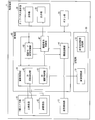
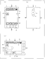
- FIG. 1 It is a functional block diagram which shows an example of the schematic function of the portable terminal which concerns on one Embodiment of this invention. It is a figure which shows the external appearance of the said portable terminal.
- A) of the figure shows the surface (front surface) where the touch panel display unit is provided in the portable terminal
- (b) of the figure shows the binocular camera part provided in the portable terminal.
- the surface (back surface) is shown.
- (c) of the figure has shown the positional relationship of the touchscreen display part of the said portable terminal, and the binocular camera part provided in the back surface.
- FIG. 1 It is a flowchart which shows an example of the flow of the label
- An example of screen display in each posture of the mobile terminal in 2D shooting mode is shown.
- (A), (b), (c), and (d) of the figure show the mobile terminal postures of “home”, “rotate 90 degrees right”, “rotate 180 degrees right”, and “270 degrees right”, respectively.
- An example of screen display in the case of “rotation (rotation 90 degrees left)” is shown.
- An example of screen display in each posture of the mobile terminal in 3D shooting mode is shown.
- (A), (b), (c), and (d) of the figure show the mobile terminal postures of “home”, “rotate 90 degrees right”, “rotate 180 degrees right”, and “270 degrees right”, respectively.
- FIG. 1 An example of screen display in the case of “rotation (rotation 90 degrees left)” is shown. It is a figure which illustrates about the notification of the warning message in 3D imaging
- photography mode is shown.
- (A), (b), (c), and (d) of the figure show the mobile terminal postures of “home”, “rotate 90 degrees right”, “rotate 180 degrees right”, and “270 degrees right”, respectively.
- photography mode is shown.
- (A), (b), (c), and (d) of the figure show the mobile terminal postures of “home”, “rotate 90 degrees right”, “rotate 180 degrees right”, and “270 degrees right”, respectively.
- An example of screen display in the case of “rotation (rotation 90 degrees left)” is shown.
- photography mode is shown.
- (A), (b), (c), and (d) of the figure show the mobile terminal postures of “home”, “rotate 90 degrees right”, “rotate 180 degrees right”, and “270 degrees right”, respectively.
- An example of screen display in the case of “rotation (rotation 90 degrees left)” is shown.
- FIGS. 1 to 13 An embodiment of the present invention will be described with reference to FIGS. 1 to 13 as follows.
- FIG. 2 is a diagram illustrating an appearance of the mobile terminal 1.
- the mobile terminal 1 is illustratively a high-function mobile terminal, a so-called smartphone, a tablet information terminal, or the like.
- the mobile terminal 1 also includes a binocular camera unit (two imaging units) 10 for performing 2D imaging and 3D imaging, and a touch panel display unit (sign display unit) 20 for performing a touch operation.
- FIG. 2A shows the surface of the mobile terminal 1.
- FIG. 1 shows the appearance of the surface of the mobile terminal 1.
- a touch panel display unit 20 and a button unit 23 are provided on the surface of the mobile terminal 1.
- the touch panel display unit 20 receives a touch input and displays a screen.
- the button unit 23 is a hardware button for performing various operations of the mobile terminal 1.
- the mobile terminal 1 includes a binocular camera unit 10 that performs 2D shooting and 3D shooting.
- the twin-lens camera unit 10 includes a main imaging unit (imaging unit) 11 and a sub imaging unit (imaging unit) 12.
- FIG. 2 (c) shows a basic posture when shooting a subject in 2D shooting mode (posture tracking mode) for performing 2D shooting or 3D shooting mode (orientation maintaining mode) for performing 3D shooting.
- the position of the binocular camera unit 10 provided on the back surface is indicated by a dotted line.
- the up, down, left, and right sides of the mobile terminal 1 are indicated by arrows T, B, L, and R.
- the direction of the arrow B is aligned with the direction of gravity.
- the direction of arrow B is downward as viewed from the user.
- the direction of the arrow T is the upward direction in the basic posture at the time of shooting.
- the main imaging unit 11 is positioned on the left side (in the direction of arrow L), and the sub imaging unit 12 is positioned on the right side (in the direction of arrow R).
- a home posture normal posture
- the home posture in the 2D shooting mode and the home posture in the 3D shooting mode may be different.
- the home posture in the 2D shooting mode may be set to the state shown in FIG.
- the main imaging unit 11 captures a planar image.
- the main imaging unit 11 captures the left eye image
- the sub imaging unit 12 captures the right eye image.
- FIG. 1 is a functional block diagram illustrating the functions of the mobile terminal 1.
- the mobile terminal 1 includes a twin-lens camera unit 10, a posture detection unit (posture detection means) 13, a touch panel display unit 20, a button unit 23, a storage unit 30, and a control unit 40.
- the twin-lens camera unit 10 is for photographing an object and acquiring an image. As described above, the twin-lens camera unit 10 includes the main imaging unit 11 and the sub imaging unit 12.
- Each of the main imaging unit 11 and the sub imaging unit 12 can be realized by an optical system and an imaging device (CCD (Charge-Coupled Device), CMOS (Complementary Metal-Oxide-Semiconductor), etc.).
- CCD Charge-Coupled Device
- CMOS Complementary Metal-Oxide-Semiconductor
- the twin-lens camera unit 10 corresponds to two shooting modes: a 2D shooting mode by the main imaging unit 11 and a 3D shooting mode by the main imaging unit 11 and the sub-imaging unit 12.
- the binocular camera unit 10 can shoot not only still images but also moving images. In the following description, shooting of a still image will be described unless otherwise specified.
- the main imaging unit 11 captures the left eye image, and the sub imaging unit 12 captures the right eye image. Then, the main imaging unit 11 transmits the captured left eye image as left eye image data to the control unit 40. In addition, the sub imaging unit 12 transmits the captured right eye image to the control unit 40 as right eye image data.
- the main imaging unit 11 images the subject, and transmits a planar image obtained by the imaging to the control unit 40 as planar image data.
- the binocular camera unit Data transmitted by 10 is referred to as photographed image data.
- the posture detection unit 13 is for detecting the posture of the mobile terminal 1.
- the posture detection unit 13 can be realized by, for example, a triaxial acceleration sensor that detects the direction of gravity and the like.
- the attitude refers to, for example, the rotation of the terminal casing around an axis perpendicular to the display screen of the touch panel display unit 20.
- the posture can be indicated, for example, by how much the downward direction of the home posture (the direction of the arrow B shown in FIGS. 2A to 2C) is rotated from the direction of gravity.
- the attitude detection unit 13 generates attitude data indicating the detected attitude, and transmits the generated attitude data to the control unit 40.
- the touch panel display unit 20 includes an operation unit 21 that accepts a contact operation and a display unit (sign display means) 22 that performs screen display.
- the operation unit 21 detects the contact operation position on the display screen of the display unit 22, and transmits operation data based on the detected contact operation position to the control unit 40.
- a method for the operation unit 21 to detect the contact operation position for example, a matrix switch, a resistive film method, a surface acoustic wave method, an infrared method, an electromagnetic induction method, a capacitance method, and an image of an object A method of detecting (light sensor method) and the like.
- the present invention is not limited to this, and various methods can be appropriately applied to the method for detecting the contact operation position.
- the display unit 22 has a display screen for displaying image data, receives image data from the control unit 40, and displays an image on the display screen based on the received image data.
- the display unit 22 can be realized by, for example, an LCD (Liquid Crystal Display), a PDP (Plasma Display Panel), an EL (Electroluminescence) display, or the like.
- the button unit 23 is a hardware button provided on the surface of the mobile terminal 1 as described above.
- the button unit 23 creates operation data corresponding to the user's operation and transmits it to the control unit 50.
- the storage unit 30 stores various data and programs.
- the control unit 40 controls the various functions of the mobile terminal 1 in an integrated manner. Details of the configurations of the storage unit 30 and the control unit 40 will be described below.
- the storage unit 30 includes an image storage unit 31 and a display control setting storage unit 32.
- the image storage unit 31 stores image data photographed by the binocular camera unit 10 under the control of the photographing control unit 41.
- the image data is identified by, for example, a file name.
- the image data is a variety of file formats depending on whether it is a planar image in 2D shooting mode, a stereoscopic image in 3D shooting mode, moving image data, or still image data. Can be adopted.
- the file name may include an extension indicating the file format.
- the image data stored in the image storage unit 31 can be transmitted to the touch panel display unit 20 via the control unit 40 and reproduced on the display unit 22.
- the display control setting storage unit 32 stores display control settings indicating display settings for the touch panel display unit 20.
- the display control setting is information indicating association between the attitude of the mobile terminal 1 and the direction of the sign display. Details of the sign will be described later.
- the display control settings are roughly divided into two systems: still image settings and movie settings.
- each system there are two types of display control settings: a 2D shooting mode display control setting used in the 2D shooting mode and a 3D shooting mode display control setting used in the 3D shooting mode.
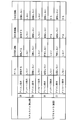
- FIG. 3 is a table showing a specific example of the display control setting.
- a still image setting “still camera (still image)” and a moving image setting “video camera (moving image)” are defined separately. Further, in each of the still image setting and the moving image setting, 2D shooting mode display control setting (denoted as “2D” in the figure) and 3D shooting mode display control setting (denoted as “3D” in the figure). Is defined.
- icon settings denoted as “icon display” in the figure
- message settings denoted as “message display” in the figure
- the operation in each posture of the mobile terminal 1 is set for each of “icon display” and “message display”.
- the posture of the mobile terminal 1 includes “home”, “left 90 degree rotation”, “right 90 degree rotation”, and “180 degree rotation”.
- “Rotate” is set for “Home”, “Rotate 90 degrees left”, and “Rotate 90 degrees right”. “Rotate” indicates that the icon is rotated in accordance with the attitude of the mobile terminal 1 so that the downward direction of the icon matches the direction of gravity. Therefore, from the user's viewpoint, the top and bottom of the icon does not change regardless of the attitude of the mobile terminal 1.
- control unit 40 specifically includes a shooting control unit 41, a shooting mode switching control unit (mode switching unit) 45, a sign drawing unit (sign display unit, notification unit) 46, and an image display.
- the configuration includes a control unit 47.
- the imaging control unit 41 controls the binocular camera unit 10 to acquire a captured image. Further, the imaging control unit 41 transfers the image data captured by the main imaging unit 11 to the image display control unit 47.
- the imaging control unit 41 generates stereoscopic image data from the image data captured by the main imaging unit 11 and the sub imaging unit 12, and transfers the stereoscopic image data to the image display control unit 47.
- the imaging control unit 41 includes a 3D imaging control unit 42 that controls the 3D imaging mode, and a 2D imaging control unit (planar image imaging unit) 43 that controls the 2D imaging mode.
- a 3D imaging control unit 42 that controls the 3D imaging mode
- a 2D imaging control unit (planar image imaging unit) 43 that controls the 2D imaging mode.
- the 3D shooting control unit 42 acquires captured image data in the 3D shooting mode, and generates a stereoscopic image from the acquired captured image data.
- the 3D shooting control unit 42 generates a stereoscopic image as follows. First, a subject is imaged by controlling the main imaging unit 11 and the sub imaging unit 12, and left eye image data and right eye image data are received from the main imaging unit 11 and the sub imaging unit 12, respectively.
- the 3D imaging control unit 42 generates stereoscopic image data by integrating the right eye image data with the left eye image data.
- the 3D imaging control unit 42 exemplarily handles the left eye image data as the main and the right eye image data as the subordinate in the generation of the stereoscopic image data.
- the 3D shooting control unit 42 stores the generated stereoscopic image data in the image storage unit 31.
- the 2D imaging control unit 43 controls the main imaging unit 11 to perform imaging in the 2D imaging mode, and acquires planar image data obtained by imaging from the main imaging unit 11.
- the 2D imaging control unit 43 stores the acquired planar image data in the image storage unit 31.
- the shooting mode switching control unit 45 switches the shooting mode between the 2D shooting mode and the 3D shooting mode in accordance with an operation on the touch panel display unit 20.
- the shooting mode switching control unit 45 transmits a shooting mode switching instruction to the shooting control unit 41 in accordance with the operation data of the mode switching operation transmitted from the touch panel display unit 20.
- the sign drawing unit 46 draws a sign to be displayed on the display unit 22 of the touch panel display unit 20.
- the sign indicates information and is configured so that the user can distinguish the vertical direction.
- Specific examples of the signs include indicators for displaying various types of information, and icons that can be distinguished from each other, such as characters, figures, symbols, and icons formed by combining them.
- Another specific example of the sign is a text message such as help or warning.
- image data representing an icon, character information constituting a character message, and the like may be stored in the storage unit 30.
- the sign drawing unit 46 determines the direction and arrangement of the sign display screen.
- the direction on the display screen of the sign is, for example, the direction of character display.
- marker is the two-dimensional coordinate expression which makes the origin the coordinate on the upper left of the display part 22, for example.
- the arrangement of the signs may be defined in advance or may be changeable according to user settings.
- the sign drawing unit 46 specifically includes a sign including an icon rotated in accordance with the detected attitude of the mobile terminal 1 in a predetermined arrangement according to the display control setting stored in the display control setting storage unit 32. Generate image data. In addition, the sign drawing unit 46 generates sign image data including a character message at a predetermined position according to the detected attitude of the mobile terminal 1 in accordance with the display control setting stored in the display control setting storage unit 32.
- the sign drawing unit 46 transmits the drawn sign image data to the image display control unit 47.
- the image display control unit 47 controls screen display on the display unit 22 of the touch panel display unit 20. Specifically, the image display control unit 47 synthesizes the image data transmitted from the imaging control unit 41 and the image data of the sign transmitted from the sign drawing unit 46 and transmits them to the display unit 22.
- the following signs are displayed on the display screen of the touch panel display unit 20 according to the sign image data generated by the sign drawing unit 46.
- an indicator part (sign) D1 As shown in the figure, on the display screen of the touch panel display unit 20, an indicator part (sign) D1, a photographing button (sign) BT1, and a 2D / 3D mode switching button (sign) BT2 are displayed.
- the sign drawing unit 46 draws various information related to the camera function of the mobile terminal 1 in the indicator unit D1.
- the indicator portion D1 exemplarily displays three types of setting information and the remaining battery level.
- the three types of setting information shown in the indicator section D1 are resolution, scene / focus setting, and shooting mode from the left side.
- FIG. 2A shows a display example of the indicator part D1 in the 2D shooting mode. That is, in this case, “5M”, “STDAUTO”, and “2D mode” are displayed on the indicator section D1 from the left as setting information.
- FIG. 2C shows a display example of the indicator section D1 in the 3D shooting mode. That is, in this case, “FULLHD”, “STDAUTO”, and “3D mode” are displayed as setting information from the left side on the indicator section D1.
- the photographing button BT1 and the 2D / 3D mode switching button BT2 are soft buttons for operating the camera function.
- the shooting button BT1 is used to instruct the shooting control unit 41 to shoot a still image in each of the 2D shooting mode and the 3D shooting mode.
- a caption “shooting” is shown in the shooting button BT1.
- the 2D / 3D mode switching button BT2 is for causing the shooting mode switching control unit 45 to switch the shooting mode.
- the caption “2D switching” (see FIG. 2C) in the 3D shooting mode is “3D switching” in the 2D shooting mode (see FIG. 2A).
- the caption is shown.
- the user can discriminate up, down, left, and right according to the direction of the caption characters shown in the shooting button BT1 and the 2D / 3D mode switching button BT2.
- the discrimination by the direction of the character is shown.
- the present invention is not limited to this, and the orientation can be discriminated by adding a symbol such as an arrow to the caption. Good. The same applies to the indicator part D1.
- the display screen of the touch panel display unit 20 includes a camera screen P1 that displays a captured image captured by the binocular camera unit 10.
- menu buttons for selecting various operations / options from the menu may be displayed on the display screen.
- FIG. 4 is a flowchart illustrating an example of the flow of the sign display process in the mobile terminal 1.
- the sign drawing unit 46 determines the shooting mode (S11).
- the shooting mode is set to the 2D shooting mode by the shooting mode switching control unit 45 (2D in S11)
- the posture detection unit 13 detects the posture of the mobile terminal 1 (S12).
- the shooting mode switching control unit 45 notifies the sign drawing unit 46 of the 2D shooting mode as the shooting mode (2D in S11)
- the sign drawing unit 46 notifies the posture detection unit 13 of the posture of the mobile terminal 1. Instruct detection.
- the posture detection unit 13 that has received the instruction detects the posture of the mobile terminal 1 (S12), and notifies the sign drawing unit 46 of the detected posture of the mobile terminal 1.
- the sign drawing unit 46 draws an icon corresponding to the attitude of the mobile terminal 1 in accordance with the display control setting for the still image-2D-icon display shown in FIG. 3 (S13). That is, when the orientation of the mobile terminal 1 is “home”, “left 90 degree rotation”, and “right 90 degree rotation”, the icon is drawn so that the downward direction of the icon always matches the direction of gravity.
- the sign drawing unit 46 performs display on the display unit 22 based on the display control setting information read from the display control setting storage unit 32 and the attitude of the mobile terminal 1 received from the attitude detection unit 13.
- the shooting mode switching control unit 45 3D in S11
- the sign drawing unit 46 is set to “do not rotate” in each posture.
- the icon is displayed while maintaining the orientation of the icon in the home posture regardless of the posture (S14).
- the sign drawing unit 46 receives the display control setting information from the display control setting storage unit 32. Read. In the display control setting information of FIG. 3, “not rotate” is set for each posture in the still image-3D-icon display. Therefore, the sign drawing unit 46 does not depend on the posture of the mobile terminal 1 and the icon in the home posture. Is displayed while maintaining the orientation of (S14).
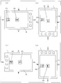
- FIG. 5A shows an example of screen display when the attitude of the mobile terminal 1 is “home”.
- the image captured by the main imaging unit 11 is displayed on the camera screen P1.
- the subject X is shown in the image.
- a shooting button BT1 and a 2D / 3D mode switching button BT2 are displayed on the display screen of the touch panel display unit 20, a shooting button BT1 and a 2D / 3D mode switching button BT2 are displayed.
- the direction of the caption characters shown in the buttons of the shooting button BT1 and the 2D / 3D mode switching button BT2, that is, up, down, left, and right, is the same as the up, down, left, right (arrows T, B, L, and R) of the mobile terminal 1. I'm doing it. The same applies to the indicator part D1.
- the shooting button BT1 is arranged at the lower center of the display screen.
- the 2D / 3D mode switching button BT2 is arranged on the left side slightly above the display screen.
- FIG. 5B shows an example of screen display in a posture in which the mobile terminal 1 in the “home” posture is rotated 90 degrees to the right.
- the direction of the button or the like is rotated in the screen display so that the direction of the caption character seen from the user does not change. That is, the direction of the character of the caption in the shooting button BT1 and the 2D / 3D mode switching button BT2 is rotated in the screen display. The same applies to the display of the indicator part D1.
- FIG. 5C shows an example of screen display when the attitude of the mobile terminal 1 is further rotated 90 degrees to the right from the state of FIG. 5B. That is, the posture of the portable terminal 1 shown in FIG. 5C is a posture rotated 180 degrees to the right from the “home” posture. The downward direction (arrow B) of the mobile terminal 1 is directed upward in the drawing.
- FIG. 5D shows an example of screen display when the attitude of the mobile terminal 1 is further rotated 90 degrees to the right from the state of FIG. 5C. That is, the posture of the mobile terminal 1 shown in FIG. 5D is a posture rotated to the right by 270 degrees from the “home” posture. Or, in other words, the posture of the mobile terminal 1 shown in FIG. 5D is a state in which the posture of the mobile terminal 1 is rotated 90 degrees to the left from the “home” posture.
- the direction of the caption characters in the shooting button BT1 and the 2D / 3D mode switching button BT2 is rotated on the screen display so that the direction of the caption characters seen from the user does not change.
- the mobile terminal 1 If the attitude of the mobile terminal 1 is further rotated 90 degrees to the right from the attitude of the mobile terminal 1 shown in FIG. 5D, the mobile terminal 1 returns to the attitude shown in FIG.
- FIG. 6A shows an example of screen display when the attitude of the mobile terminal 1 is “home”.
- the image captured by the main imaging unit 11 is displayed on the camera screen P1.
- the subject X is shown in the image.
- a shooting button BT1 and a 2D / 3D mode switching button BT2 are displayed on the display screen of the touch panel display unit 20, a shooting button BT1 and a 2D / 3D mode switching button BT2 are displayed.
- the direction of the caption characters shown in the buttons of the shooting button BT1 and the 2D / 3D mode switching button BT2, that is, up, down, left, and right, is the same as the up, down, left, right (arrows T, B, L, and R) of the mobile terminal 1. I'm doing it. The same applies to the indicator part D1.
- the arrangement of the shooting button BT1 and the 2D / 3D mode switching button BT2 is the same as the arrangement shown in FIG. That is, the shooting button BT1 is arranged at the lower center of the display screen. Further, the 2D / 3D mode switching button BT2 is arranged on the left side slightly above the display screen.
- FIG. 6B shows an example of screen display in a posture in which the mobile terminal 1 in the “home” posture is rotated 90 degrees to the right.
- buttons and the like in the “home” posture (see FIG. 6A) is maintained in the screen display.
- the display state of buttons and the like appears to be rotated 90 degrees to the right as the mobile terminal 1 rotates. The same applies to the display of the indicator part D1.
- FIG. 6C shows an example of a screen display when the attitude of the mobile terminal 1 is further rotated 90 degrees to the right from the state of FIG. 6B. That is, the posture of the mobile terminal 1 shown in FIG. 6C is a posture rotated 180 degrees to the right from the “home” posture.
- FIG. 6D shows an example of screen display when the attitude of the mobile terminal 1 is further rotated 90 degrees to the right from the state of FIG. 6C. That is, the posture of the mobile terminal 1 shown in FIG. 6D is a posture rotated to the right by 270 degrees from the “home” posture. Or, in other words, the posture of the mobile terminal 1 shown in FIG. 6D is a state in which the posture of the mobile terminal 1 is rotated 90 degrees to the left from the “home” posture.
- the mobile terminal 1 includes the main imaging unit 11 and the sub imaging unit 12 that are two imaging units that capture the right-eye image and the left-eye image for generating a stereoscopic image.
- the posture detection unit 13 that detects whether or not the posture of the device is a “home” posture capable of capturing the right eye image and the left eye image by the main imaging unit 11 and the sub imaging unit 12;
- a sign drawing unit 46 that displays a distinguishable sign on the screen, a 2D shooting mode in which the sign drawing unit 46 changes the display direction of the sign on the screen display according to the posture detected by the posture detection unit 13, and the sign drawing
- the unit 46 includes a shooting mode switching control unit 45 that switches a 3D shooting mode that maintains the direction of display of the sign in the screen display to the display direction in the “home” posture, and the shooting mode switching control unit 4.
- When performing imaging of the right-eye image and the left eye image by the main image pickup unit 11 and the sub-imaging unit 12 is configured to switch to 3
- FIG. 7 is a diagram illustrating an example in which a warning message is notified when the attitude of the mobile terminal 1 is upside down in the 3D shooting mode.
- a warning message (warning notification) MSG1 such as “I hold the terminal upside down” may be sent in the attitude of the mobile terminal 1 shown in FIG.
- the attitude “180 ° rotation” of the still image-3D-message display is defined.
- the warning message may be hidden. This is because it is assumed that the user has intentionally photographed in a state where the posture of the mobile terminal 1 is upside down.
- warning message MSG1 may be notified again at the end of shooting or after a predetermined time has elapsed.
- a warning may be given by voice.
- FIG. 8A shows an example of screen display when the attitude of the mobile terminal 1 is “home”.
- a moving image shooting icon IC01 and a 2D / 3D mode switching button BT2 are displayed.
- the moving image shooting icon IC01 is an icon indicating the moving image shooting mode.
- the moving image shooting icon IC01 is arranged below the display screen.
- the 2D / 3D mode switching button BT2 is used to switch between the 2D shooting mode and the 3D shooting mode in moving image shooting.
- the 2D / 3D mode switching button BT2 is arranged on the left side of the display screen.
- a caption “2D switching” is shown in the 2D / 3D mode switching button BT2.
- the direction of the characters of the caption shown in the button of the 2D / 3D mode switching button BT2 that is, up, down, left, right matches the up, down, left, right (arrows T, B, L, and R) of the mobile terminal 1.
- FIG. 8B shows an example of screen display in a posture in which the mobile terminal 1 in the “home” posture is rotated 90 degrees to the right.
- buttons and the like in the “home” posture (see FIG. 8A) is maintained in the screen display.
- the display state of buttons and the like appears to be rotated 90 degrees to the right as the mobile terminal 1 rotates. The same applies to the display of the indicator part D1.
- the moving image shooting icon IC01 rotates on the screen display according to the rotation of the posture so that the direction viewed from the user does not change.
- FIG. 8B illustration is omitted for convenience of explanation, but in accordance with the definition of “display video 3D-message” in the display control setting posture “rotate right 90 degrees” shown in FIG.
- a warning message (warning notification) may be notified.
- the warning message notified in the posture shown in FIG. 8B may be the same as the warning message MSG2 in FIG. 8C described below, or “right 90 degree rotated posture”. It may be a message indicating that there is.
- FIG. 8C shows an example of a screen display when the attitude of the mobile terminal 1 is further rotated 90 degrees to the right from the state of FIG. 8B. That is, the posture of the mobile terminal 1 shown in FIG. 8C is a posture rotated 180 degrees to the right from the “home” posture.
- the moving image shooting icon IC01 rotates on the screen display according to the rotation of the posture so that the direction viewed from the user does not change.
- the display of the display control setting orientation “180 degree rotation” shown in FIG. 3 is defined as “moving image-3D-message display”, in the orientation shown in FIG. (Warning notification) MSG2 is notified.
- the content of the warning message MSG2 is the same as that of the warning message MSG1 described above.
- FIG. 8D shows an example of screen display when the attitude of the mobile terminal 1 is further rotated 90 degrees to the right from the state of FIG. 8C. That is, the posture of the mobile terminal 1 shown in FIG. 8D is a posture rotated to the right by 270 degrees from the “home” posture. Or, in other words, the posture of the mobile terminal 1 shown in FIG. 8D is a state in which the posture of the mobile terminal 1 is rotated 90 degrees to the left from the “home” posture.
- the moving image shooting icon IC01 rotates on the screen display according to the rotation of the posture so that the direction viewed from the user does not change.
- the sign drawing unit 46 arranges the shooting button BT1 at the upper right of the display screen as seen from the user regardless of the orientation of the mobile terminal 1, and the direction of the characters is seen in the same direction as seen from the user. Like that.
- a specific description will be given with reference to (a) to (d) of FIG.
- FIG. 9A shows a modification of the screen display when the attitude of the mobile terminal 1 is “home”.
- a shooting button BT1 and a 2D / 3D mode switching button BT2 are displayed.
- the captions of the shooting button BT1 and the 2D / 3D mode switching button BT2 are, for example, “shooting” and “3D switching”, respectively.
- the direction of the caption characters shown in the buttons of the shooting button BT1 and the 2D / 3D mode switching button BT2, that is, up, down, left, and right, is the same as the up, down, left, right (arrows T, B, L, and R) of the mobile terminal 1. I'm doing it.
- the shooting button BT1 is arranged at the upper right of the display screen.
- the 2D / 3D mode switching button BT2 is arranged at the left center of the display screen.
- the shooting button BT1 is arranged at the upper right of the display screen when viewed from the user, so that the user can easily touch the shooting button BT1 by the operation with the right hand.
- the arrangement is not limited to this, and the arrangement may be reverse to the above so that it can be easily touched by an operation with the left hand.
- you may comprise so that the position of right and left can be switched by setting.
- FIG. 9B shows an example of screen display in a posture in which the mobile terminal 1 in the “home” posture is rotated 90 degrees to the right.
- the direction of the button or the like is rotated in the screen display so that the direction of the caption character seen from the user does not change. That is, the direction of the character of the caption in the shooting button BT1 and the 2D / 3D mode switching button BT2 is rotated in the screen display.
- the shooting button BT1 is arranged at the upper right of the display screen as viewed from the user.
- the 2D / 3D mode switching button BT2 is disposed at the center on the left side of the display screen as viewed from the user.
- the positional relationship between the shooting button BT1 and the 2D / 3D mode switching button BT2 as seen from the user does not change. For this reason, the user can easily touch the shooting button BT1 by an operation with the right hand.
- FIG. 9C shows an example of a screen display when the attitude of the mobile terminal 1 is further rotated 90 degrees to the right from the state of FIG. 9B. That is, the posture of the mobile terminal 1 shown in FIG. 9C is a posture rotated 180 degrees to the right from the “home” posture. The downward direction (arrow B) of the mobile terminal 1 is directed upward in the drawing.
- the shooting button BT1 is arranged on the upper right of the display screen as viewed from the user.
- the 2D / 3D mode switching button BT2 is disposed at the center on the left side of the display screen as viewed from the user.
- FIG. 9D shows an example of screen display when the attitude of the mobile terminal 1 is further rotated 90 degrees to the right from the state of FIG. 9C. That is, the posture of the mobile terminal 1 shown in FIG. 9D is a posture rotated to the right by 270 degrees from the “home” posture. Or, in other words, the posture of the mobile terminal 1 shown in FIG. 9D is a state in which the posture of the mobile terminal 1 is rotated 90 degrees to the left from the “home” posture.
- the direction of the caption characters in the shooting button BT1 and the 2D / 3D mode switching button BT2 is rotated on the screen display so that the direction of the caption characters seen from the user does not change.
- the shooting button BT1 is arranged on the upper right of the display screen as viewed from the user.
- the 2D / 3D mode switching button BT2 is disposed at the center on the left side of the display screen as viewed from the user.
- the mobile terminal 1 If the attitude of the mobile terminal 1 is further rotated 90 degrees to the right from the attitude of the mobile terminal 1 shown in FIG. 9 (d), the mobile terminal 1 returns to the attitude shown in FIG. 9 (a).
- the shooting button BT1 is arranged on the upper right of the display screen as viewed from the user regardless of the attitude of the mobile terminal 1. For this reason, the user can easily touch the shooting button BT ⁇ b> 1 by an operation with the right hand regardless of the posture of the mobile terminal 1.
- FIG. 10 is a diagram illustrating a modified example of the screen display in each posture in the 3D shooting mode.
- the notation of the camera screen P1 and the indicator part D1 is omitted.
- the sign drawing unit 46 arranges the shooting button BT1 at the upper right of the display screen when viewed from the user in the “home” posture. Further, the sign drawing unit 46 maintains the position of the shooting button BT1 in the “home” posture regardless of the posture of the mobile terminal 1.
- FIG. 10A shows an example of screen display when the attitude of the mobile terminal 1 is “home”. As shown in FIG. 10A, a shooting button BT1 and a 2D / 3D mode switching button BT2 are displayed on the display screen of the touch panel display unit 20.
- the captions of the shooting button BT1 and the 2D / 3D mode switching button BT2 are, for example, “shooting” and “3D switching”, respectively.
- the direction of the caption characters shown in the buttons of the shooting button BT1 and the 2D / 3D mode switching button BT2, that is, up, down, left, and right, is the same as the up, down, left, right (arrows T, B, L, and R) of the mobile terminal 1. I'm doing it.
- the arrangement of the shooting button BT1 and the 2D / 3D mode switching button BT2 is the same as the arrangement shown in FIG. That is, the shooting button BT1 is arranged at the upper right of the display screen.
- the 2D / 3D mode switching button BT2 is arranged at the left center of the display screen.
- the shooting button BT1 is arranged at the upper right of the display screen when viewed from the user, so that the user can easily touch the shooting button BT1 by the operation with the right hand.
- FIG. 10B shows an example of screen display in a posture in which the mobile terminal 1 in the “home” posture is rotated 90 degrees to the right.
- the display state of the buttons and the like in the “home” posture (see FIG. 10A) is maintained in the screen display.
- the display state of buttons and the like appears to be rotated 90 degrees to the right as the mobile terminal 1 rotates.
- the photographing button BT1 is arranged at the lower right of the display screen as viewed from the user.
- FIG. 10C shows an example of screen display when the attitude of the mobile terminal 1 is further rotated 90 degrees to the right from the state of FIG. 10B. That is, the posture of the mobile terminal 1 shown in FIG. 10C is a posture rotated 180 degrees to the right from the “home” posture.
- the display state of the buttons and the like in the “home” posture (see FIG. 10A) is maintained in the screen display.
- the direction of the button or the like seems to be upside down from the direction in the “home” posture.
- the photographing button BT1 is arranged at the lower left of the display screen as viewed from the user.
- FIG. 10 (d) shows an example of a screen display when the attitude of the mobile terminal 1 is further rotated 90 degrees to the right from the state of FIG. 10 (c). That is, the posture of the mobile terminal 1 shown in FIG. 10D is a posture rotated to the right by 270 degrees from the “home” posture. Or, in other words, the posture of the mobile terminal 1 shown in FIG. 10D is a state in which the posture of the mobile terminal 1 is rotated 90 degrees to the left from the “home” posture.
- the shooting button BT1 is arranged at the upper left of the display screen as viewed from the user.
- the mobile terminal 1 If the attitude of the mobile terminal 1 is further rotated 90 degrees to the right from the attitude of the mobile terminal 1 shown in FIG. 10 (d), the mobile terminal 1 returns to the attitude shown in FIG. 10 (a).
- the shooting button BT1 is arranged on the upper right of the display screen as viewed from the user. Therefore, when the attitude of the mobile terminal 1 is “home”, the user can easily touch the shooting button BT1 by an operation with the right hand.
- FIG. 11 is a diagram illustrating another modified example of the screen display in each posture in the 3D shooting mode.
- the notation of the camera screen P1 and the indicator part D1 is omitted for convenience of explanation.
- the sign drawing unit 46 arranges the shooting button BT1 at the upper right of the display screen as viewed from the user regardless of the posture of the mobile terminal 1, and sets the direction of the characters of the shooting button BT1 to “home posture”. Keep the orientation at.
- the sign drawing unit 46 changes the arrangement of the shooting button BT1 on the display screen of the touch panel unit 20 according to the posture of the mobile terminal 1, and changes the orientation of the characters of the shooting button BT1 to “home posture”. Keep the orientation at.
- FIG. 11A shows an example of a screen display when the attitude of the mobile terminal 1 is “home”.
- the caption and arrangement of the shooting button BT1 and 2D / 3D mode switching button BT2 displayed on the screen display are the same as in the example shown in FIG.
- FIG. 11B shows an example of screen display in a posture in which the mobile terminal 1 in the “home” posture is rotated 90 degrees to the right.
- the relative positional relationship as viewed from the user is displayed so as to be the same as in the “home” posture. That is, the shooting button BT1 is arranged at the upper right of the display screen as viewed from the user. In addition, the 2D / 3D mode switching button BT2 is disposed at the center on the left side of the display screen as viewed from the user.
- FIG. 11C shows an example of a screen display when the attitude of the mobile terminal 1 is further rotated 90 degrees to the right from the state of FIG. 11B. That is, the posture of the mobile terminal 1 shown in FIG. 11C is a posture rotated 180 degrees to the right from the “home” posture.
- the caption direction of the shooting button BT1 and the 2D / 3D mode switching button BT2 seems to be upside down from the direction in the “home” posture.
- the relative positional relationship as viewed from the user is displayed so as to be the same as in the “home” posture. That is, the shooting button BT1 is arranged at the upper right of the display screen as viewed from the user. In addition, the 2D / 3D mode switching button BT2 is disposed at the center on the left side of the display screen as viewed from the user.
- FIG. 11D shows an example of screen display when the attitude of the mobile terminal 1 is further rotated 90 degrees to the right from the state of FIG. 11C. That is, the posture of the portable terminal 1 shown in FIG. 11D is a posture rotated to the right by 270 degrees from the “home” posture. Or, in other words, the posture of the mobile terminal 1 shown in FIG. 11D is a state in which the posture of the mobile terminal 1 is rotated 90 degrees to the left from the “home” posture.
- the relative positional relationship as viewed from the user is displayed so as to be the same as in the “home” posture. That is, the shooting button BT1 is arranged at the upper right of the display screen as viewed from the user. In addition, the 2D / 3D mode switching button BT2 is disposed at the center on the left side of the display screen as viewed from the user.
- the mobile terminal 1 If the orientation of the mobile terminal 1 is further rotated 90 degrees to the right from the orientation of the mobile terminal 1 shown in FIG. 11 (d), the mobile terminal 1 returns to the orientation shown in FIG. 11 (a).
- the shooting button BT1 is arranged on the upper right of the display screen as viewed from the user. Therefore, in each posture of the mobile terminal 1, the user can easily touch the shooting button BT1 by an operation with the right hand.
- FIG. 12 is a diagram illustrating still another modification example of the screen display in each posture in the 3D shooting mode.
- the camera screen P1 and the indicator part D1 are not shown for convenience of explanation.
- the sign drawing unit 46 arranges the shooting button BT1 in the center of the display screen regardless of the posture of the mobile terminal 1, and maintains the orientation of the characters of the shooting button BT1 in the “home posture” direction. To do.
- a specific description will be given with reference to (a) to (d) of FIG.
- FIG. 12A shows an example of a screen display when the attitude of the mobile terminal 1 is “home”. As shown in FIG. 12A, a shooting button BT1 and a 2D / 3D mode switching button BT2 are displayed on the display screen of the touch panel display unit 20.
- the captions of the shooting button BT1 and the 2D / 3D mode switching button BT2 are, for example, “shooting” and “3D switching”, respectively.
- the direction of the caption characters shown in the buttons of the shooting button BT1 and the 2D / 3D mode switching button BT2, that is, up, down, left, and right, is the same as the up, down, left, right (arrows T, B, L, and R) of the mobile terminal 1. I'm doing it.
- the shooting button BT1 is arranged at the center of the display screen. Further, the 2D / 3D mode switching button BT2 is arranged at the left center of the display screen.
- FIG. 12B shows an example of screen display in a posture in which the mobile terminal 1 in the “home” posture is rotated 90 degrees to the right.
- the photographing button BT1 and the 2D / 3D mode switching button BT2 the relative positional relationship as viewed from the user is displayed so as to be the same as in the “home” posture. That is, the photographing button BT1 is arranged at the center of the display screen as viewed from the user.
- the sign drawing unit 46 arranges the photographing button BT1 at the same position on the display screen as in the “home” posture.
- the 2D / 3D mode switching button BT2 is disposed at the center on the left side of the display screen as viewed from the user.
- FIG. 12C shows an example of a screen display when the attitude of the mobile terminal 1 is further rotated 90 degrees to the right from the state of FIG. That is, the posture of the mobile terminal 1 shown in FIG. 12C is a posture rotated 180 degrees to the right from the “home” posture.
- the caption direction of the shooting button BT1 and the 2D / 3D mode switching button BT2 seems to be upside down from the direction in the “home” posture.
- the relative positional relationship as viewed from the user is displayed so as to be the same as in the “home” posture. That is, the shooting button BT1 is arranged at the upper right of the display screen as viewed from the user. In addition, the 2D / 3D mode switching button BT2 is disposed at the center on the left side of the display screen as viewed from the user.
- the sign drawing unit 46 arranges the photographing button BT1 at the same position on the display screen as in the “home” posture.
- FIG. 12D shows an example of a screen display when the posture of the mobile terminal 1 is further rotated 90 degrees to the right from the state of FIG. That is, the posture of the mobile terminal 1 shown in FIG. 12D is a posture rotated to the right by 270 degrees from the “home” posture. Or, in other words, the posture of the mobile terminal 1 shown in FIG. 12D is a state in which the posture of the mobile terminal 1 is rotated 90 degrees to the left from the “home” posture.
- the relative positional relationship as viewed from the user is displayed so as to be the same as in the “home” posture. That is, the shooting button BT1 is arranged at the upper right of the display screen as viewed from the user. In addition, the 2D / 3D mode switching button BT2 is disposed at the center on the left side of the display screen as viewed from the user.
- the sign drawing unit 46 arranges the photographing button BT1 at the same position on the display screen as in the “home” posture.
- the shooting button BT1 is arranged at the same position on the display screen as viewed from the user regardless of the posture of the mobile terminal 1.
- the sign drawing unit 46 arranges the photographing button BT1 on the display screen at the same position as in the “home” posture, regardless of the posture of the mobile terminal 1.
- Modifications 1 to 3 can be changed as follows. That is, a warning message indicating that the posture of the mobile terminal 1 is upside down in the postures shown in (c) of FIG. 10, (c) of FIG. 11, and (c) of FIG. 12 may be notified. .
- the 2D / 3D mode switching button BT2 is arranged at the center on the left side of the display screen when viewed from the user before the shooting mode is switched, but at the center of the right side of the display screen when viewed from the user after the switching of the shooting mode. Become.
- the position of the 2D / 3D mode switching button BT2 may be difficult to recognize.
- the configuration of the mobile terminal 1 may be changed as follows.
- the 2D / 3D mode switching button BT2 is grayed out (indicated by a dotted line in FIG. 13) and the 2D / 3D mode switching button BT2 is arranged after the shooting mode is switched. It may indicate that it changes. Further, the photographing mode switching by the 2D / 3D mode switching button BT2 may be prohibited.
- the shooting mode switching may be accepted by a flick operation on the touch panel display unit 20 or the like.
- the posture detection unit 13 may detect the shaking of the mobile terminal 1 and switch the shooting mode.
- the mobile terminal 1 detects whether or not the orientation of the mobile device 1 is the “home” orientation in which the main imaging unit 11 and the sub imaging unit 12 can capture the right eye image and the left eye image.
- the sign drawing unit 46 changes the display direction of the sign on the screen display according to the detection unit 13, the sign drawing unit 46 that performs screen display of the sign whose direction can be determined, and the posture detected by the posture detection unit 13.
- a shooting mode switching control unit 45 that switches between a 2D shooting mode and a 3D shooting mode in which the sign drawing unit 46 maintains the display direction of the sign on the screen display in the “home” orientation.
- the control unit 45 switches to the 3D shooting mode.
- the user can recognize the attitude of the terminal from the screen display of the sign when capturing a stereoscopic image with a distinction between up and down or left and right.
- the sign display unit changes the display position of the sign on the screen display in the orientation maintaining mode according to the posture detected by the posture detection unit. .
- the position of the sign is changed according to the attitude of the terminal.
- the display position on the screen display is changed according to the attitude of the terminal, it is preferable that the position of the sign is not changed when viewed from the user.
- the display position of the sign may be the center of the screen display.
- the sign when viewed from the user, the sign may be displayed at the upper right position on the screen display regardless of the attitude of the terminal.
- the position of the sign does not change from the user's view regardless of the orientation of the terminal. Therefore, the above configuration provides convenience in operation when the sign is a soft key for instructing an operation. Improvements can be made.
- the sign can be displayed at a position that is easy for the user to see.
- the position of the sign displayed by the marker display device is displayed in the normal posture. Is preferably maintained.
- the display position of the sign is maintained at the position to be displayed in the normal posture.
- the posture detection means it is preferable to provide notification means for performing a warning notification that the vertical position of the own apparatus is reverse in an orientation corresponding to the detected attitude.
- the warning notification of the direction according to the attitude of the terminal is performed.
- the direction of the warning notification is, for example, the direction of characters.
- the two-lens imaging device includes a planar image imaging unit that captures a planar image by one of the two imaging units, and the mode switching unit is configured to perform the posture when the imaging by the planar image imaging unit is performed. It is preferable to switch to the follow mode.
- twin-lens imaging device capable of performing imaging in so-called 2D mode and 3D mode.
- twin-lens imaging device include a twin-lens digital camera and a high-function mobile phone, that is, a smartphone and a tablet-type terminal.
- the sign includes a sign for instructing the right eye image and the left eye image to be captured by the two image capturing units.
- one of the signs is a soft key for performing 3D shooting with a twin-lens camera.
- the usability of soft keys can be improved.
- the sign includes a sign for instructing mode switching to the mode switching means.
- one of the signs is a soft key for switching between 3D mode and 2D mode, for example.
- the usability of soft keys can be improved.
- the sign includes a sign for instructing the mode switching means to switch the mode, and the mode switching means has its own vertical posture reversed in the posture following mode. In this case, it is preferable to execute at least one of an indication that the vertical posture is reversed and prohibition of the change to the orientation maintaining mode.
- the terminal When switching from the attitude tracking mode, which does not distinguish between up / down / left / right, to the orientation maintenance mode with distinction between up / down / left / right, the terminal may be upside down in the orientation maintenance mode.
- Each block of the mobile terminal 1 described above may be realized in hardware by a logic circuit formed on an integrated circuit (IC chip), or may be realized in software using a CPU (Central Processing Unit). May be.
- IC chip integrated circuit
- CPU Central Processing Unit
- each device includes a CPU that executes instructions of a program that realizes each function, a ROM (Read (Memory) that stores the program, a RAM (Random Memory) that expands the program, the program, and various types
- a storage device such as a memory for storing data is provided.
- An object of the present invention is to provide a recording medium in which a program code (execution format program, intermediate code program, source program) of a control program of each of the above devices, which is software that realizes the above-described functions, is recorded so as to be readable by a computer. This can also be achieved by supplying to each of the above devices and reading and executing the program code recorded on the recording medium by the computer (or CPU or MPU).
- Examples of the recording medium include tapes such as magnetic tape and cassette tape, magnetic disks such as floppy (registered trademark) disks / hard disks, and CD-ROM / MO / MD / DVD / CD-R / Blu-ray disks (registered trademarks). ) And other optical disks, IC cards (including memory cards) / optical cards, semiconductor memories such as mask ROM / EPROM / EEPROM / flash ROM, PLD (Programmable logic device) and FPGA ( Logic circuits such as Field Programmable Gate Array can be used.
- tapes such as magnetic tape and cassette tape
- magnetic disks such as floppy (registered trademark) disks / hard disks
- CD-ROM / MO / MD / DVD / CD-R / Blu-ray disks registered trademarks
- IC cards including memory cards
- semiconductor memories such as mask ROM / EPROM / EEPROM / flash ROM, PLD (Programmable logic device) and FPGA ( Logic circuits
- each of the above devices may be configured to be connectable to a communication network, and the program code may be supplied via the communication network.
- the communication network is not particularly limited as long as it can transmit the program code.
- the Internet intranet, extranet, LAN, ISDN, VAN, CATV communication network, virtual private network (Virtual Private Network), telephone line network, mobile communication network, satellite communication network, etc. can be used.
- the transmission medium constituting the communication network may be any medium that can transmit the program code, and is not limited to a specific configuration or type.
- wired lines such as IEEE 1394, USB, power line carrier, cable TV line, telephone line, ADSL (Asymmetric Digital Subscriber Line) line, infrared rays such as IrDA and remote control, Bluetooth (registered trademark), IEEE 802.11 wireless, HDR ( It can also be used by wireless such as High Data Rate, NFC (Near Field Communication), DLNA (Digital Living Network Alliance), mobile phone network, satellite line, and terrestrial digital network.
- the present invention can also be realized in the form of a computer data signal embedded in a carrier wave in which the program code is embodied by electronic transmission.
- the present invention can be used for a smartphone equipped with a twin-lens camera unit and a touch panel display unit.
Landscapes
- Engineering & Computer Science (AREA)
- Multimedia (AREA)
- Theoretical Computer Science (AREA)
- Signal Processing (AREA)
- Physics & Mathematics (AREA)
- General Physics & Mathematics (AREA)
- General Engineering & Computer Science (AREA)
- Human Computer Interaction (AREA)
- Computer Hardware Design (AREA)
- Studio Devices (AREA)
- Testing, Inspecting, Measuring Of Stereoscopic Televisions And Televisions (AREA)
- User Interface Of Digital Computer (AREA)
- Details Of Cameras Including Film Mechanisms (AREA)
- Stereoscopic And Panoramic Photography (AREA)
- Indication In Cameras, And Counting Of Exposures (AREA)
Abstract
携帯端末(1)は、自装置の姿勢が、主撮像部(11)および副撮像部(12)による右眼画像および左眼画像の撮像ができる正姿勢であるか否かに応じて、向きを判別可能な標識の向きを画面表示において変更する2D撮影モードと、上記標識の表示の向きを正姿勢において表示する向きに維持する3D撮影モードとを切り替え、上記2つの撮像部による上記右眼画像および上記左眼画像の撮像を行う際に、3D撮影モードに切り替える。
Description
本発明は2眼カメラを備える2眼撮像装置、その制御方法、および、制御プログラムおよびコンピュータ読み取り可能な記録媒体に関する。
近年、通信機能、情報処理機能、および、その他各種の機能を備える高機能携帯端末、いわゆるスマートフォンが市場において出回っている。
スマートフォンが備える機能は非常に様々であり、例えば、動画像再生機能、ブラウザ機能、eメール機能、スケジュール機能、およびカメラ機能などが挙げられる。
また、近年、多くのスマートフォンでは、ユーザーインターフェース(以下、UI[User Interface]と略称する)にタッチパネルが採用されており、これにより直感的な操作を実現している。
これに対して、従来の多くの携帯電話機において採用されていたような物理的なボタンの数は少なくなってきている。
このため、物理的なボタンの数が少ないスマートフォンは、端末の上下、左右の区別がつきにくい場合がある。よって、例えば、スマートフォンの機能を実行するのに適正な端末の向きなどの制約がある場合に、ユーザが適正な端末の向きを認識しにくくなることがある。
例えば、カメラ機能で撮影を行う際、ユーザが端末を上下逆に持っていた場合、撮影を行うのに適正な端末の向きをユーザが判断する必要がある。この場合、ユーザは、例えば、カメラ機能により画面内に表示される文字やアイコンの位置関係などを手がかりに端末の向きを判断することになる。
この問題について、従来、端末が適正な向きでない場合、警告を表示したり、撮影を禁止したりする技術が提案されている(特許文献1~6)。
また、端末の上下の向きに対応して自動的にUIも反転し、その向きのまま撮影可能な状態にすることも提案されている。
スマートフォンでは、平面画像の2D撮影と、立体画像の3D撮影との両方を行えるものも有る。
ここで、2D撮影における平面画像については、端末の上下左右、すなわち姿勢を特に意識することなく、撮影可能なものもある。
一方で、3D撮影における立体画像については、2眼カメラで左右の眼に対応する画像を撮影する都合上、端末の上下が逆の状態で撮影すると、画像の左右が逆となり、良好な立体視が得られないものがある。
このようなものの例としては、左に対応する画像を主カメラで撮影し、右に対応する画像をサブカメラで撮影し、主カメラで撮影した画像に対して、サブカメラで撮影した画像をシフトして、当該2つの画像を統合することで立体画像を作成するものが挙げられる。
このように、端末の姿勢を特に意識しなくてもよい2D撮影と、端末の姿勢を意識する必要のある3D撮影とが混在しているため、ユーザが端末の姿勢を認識すべきか否か混乱するおそれがある。よって、端末の姿勢を意識すべきときには、ユーザに端末の姿勢を認識させることが望まれる。
本発明は、上記問題を鑑みてなされたものであり、その目的は、上下または左右の区別がある立体画像の撮像時に、端末の姿勢を標識の画面表示によりユーザに認識させることができる2眼撮像装置、その制御方法、および、制御プログラムおよびコンピュータ読み取り可能な記録媒体を実現することにある。
上記の課題を解決するために、本発明に係る2眼撮像装置では、立体画像を生成するための右眼画像および左眼画像を撮像する2つの撮像部を備える2眼撮像装置において、自装置の姿勢が、上記2つの撮像部による上記右眼画像および上記左眼画像の撮像ができる正姿勢であるか否かを検知する姿勢検知手段と、向きを判別可能な標識の画面表示を行う標識表示手段と、上記姿勢検知手段が検知する姿勢に応じて、上記標識表示手段が上記画面表示における標識の表示の向きを変更する姿勢追従モードと、上記標識表示手段が上記画面表示における標識の表示の向きを、正姿勢において表示する向きに維持する向き維持モードとを切り替えるモード切替手段とを備え、上記モード切替手段は、上記2つの撮像部による上記右眼画像および上記左眼画像の撮像を行う際に、上記向き維持モードに切り替えることを特徴とする。
上記の課題を解決するために、本発明に係る2眼撮像装置の制御方法では、立体画像を生成するための右眼画像および左眼画像を撮像する2つの撮像部を備える2眼撮像装置の制御方法において、自装置の姿勢が、上記2つの撮像部による上記右眼画像および上記左眼画像の撮像ができる正姿勢であるか否かを検知する姿勢検知ステップと、上記姿勢検知ステップが検知する姿勢に応じて、向きを判別可能な標識の向きを画面表示において変更する姿勢追従モード処理ステップと、上記画面表示における上記標識の表示の向きを、正姿勢において表示する向きに維持する向き維持モード処理ステップと、上記2つの撮像部による上記右眼画像および上記左眼画像の撮像を行う際に、上記姿勢追従モード処理ステップから上記向き維持モードステップに切り替えるモード切替ステップとを含むことを特徴とする。
上記構成によれば、右眼画像および左眼画像の2つの画像を撮像し、これにより立体画像を生成するための撮像画像を取得する。なお、取得する撮像画像は、静止画像であってもよいし、動画であってもよい。
立体画像の生成手法の手法は、2眼カメラによって撮像した右眼画像および左眼画像の2つの画像を用いるものであれば、とくに制限はなく、従来技術、例えば、サイド・バイ・サイド方式等を採用可能である。
また、例えば、右眼画像および左眼画像のうちいずれか一方が立体画像を生成するための主画像であり、他方が、立体画像を生成するためのサブ画像であってもよい。そして、上記主画像に対して、上記サブ画像をずらすことで上記立体画像が生成できるような構成であってもよい。
また、自装置の上下は、右眼画像および左眼画像を撮像する撮像部の左右の位置関係に基づいて定まるといえる。
上記左眼画像および上記右眼画像を撮像できる正姿勢とは、左眼画像を撮像するための撮像部が、被写体に対して左側に位置し、右眼画像を撮像するための撮像部が、被写体に対して右側に位置する位置にある姿勢のことである。
また、自装置の上下が逆転すれば、左眼画像撮像用の撮像部は、被写体の右側に位置し、右眼画像撮像用の撮像部は、被写体の左側に位置することになる。
よって、上記左眼画像および上記右眼画像を撮像できる正姿勢とは、言い換えれば、2つの撮像部が地面に対して水平に位置付けられており、なおかつ、自装置の上下が逆転していない姿勢である。
また、向きを判別可能な標識とは、上下左右の識別がつくような1または複数の標識のことである。標識の例としては、画面に表示するアイコン、ボタン、およびメッセージなどが挙げられる。なお、上記構成において、画面表示はタッチパネルにより実現されていてもよい。
また、上記構成では、自装置が正姿勢でない場合でも、画面表示上の標識の向きを、正姿勢において表示する向きに維持する向き維持モードを有する。
そして、上記構成では、自装置の姿勢に応じて、画面表示上の標識の向きを変更する姿勢追従モードを有する。これは、例えば、自装置の上下姿勢が逆になっても、ユーザから見た上下が変更されないようにしたほうが、ユーザの使い勝手がよい場合があるからである。例えば、平面画像を撮像する場合などである。
上記構成では、以上のような姿勢追従モードと、向き維持モードとは切り替え可能に構成している。
さらに、上記構成によれば、立体画像を生成するための撮像画像を取得する際には、向き維持モードに切り替える。
これにより、上下または左右の区別がある立体画像の撮像時に、端末の姿勢を標識の画面表示によりユーザに認識させることができるという効果を奏する。
なお、上記2眼撮像装置は、コンピュータによって実現してもよく、この場合には、コンピュータを上記各手段として動作させることにより2眼撮像装置をコンピュータにて実現させる2眼撮像装置制御プログラムおよびそれを記録したコンピュータ読み取り可能な記録媒体も、本発明の範疇に入る。
本発明に係る2眼撮像装置は、自装置の姿勢が、2つの撮像部による右眼画像および左眼画像の撮像ができる正姿勢であるか否かを検知する姿勢検知手段と、向きを判別可能な標識の画面表示を行う標識表示手段と、上記姿勢検知手段が検知する姿勢に応じて、上記標識表示手段が上記画面表示における標識の表示の向きを変更する姿勢追従モードと、上記標識表示手段が上記画面表示における標識の表示の向きを、正姿勢において表示する向きに維持する向き維持モードとを切り替えるモード切替手段とを備え、上記モード切替手段は、上記2つの撮像部による上記右眼画像および上記左眼画像の撮像を行う際に、上記向き維持モードに切り替える構成である。
本発明に係る2眼撮像装置の制御方法は、自装置の姿勢が、2つの撮像部による右眼画像および左眼画像の撮像ができる正姿勢であるか否かを検知する姿勢検知ステップと、上記姿勢検知ステップが検知する姿勢に応じて、向きを判別可能な標識の向きを画面表示において変更する姿勢追従モード処理ステップと、上記画面表示における上記標識の表示の向きを、正姿勢において表示する向きに維持する向き維持モード処理ステップと、上記2つの撮像部による上記右眼画像および上記左眼画像の撮像を行う際に、上記姿勢追従モード処理ステップから上記向き維持モードステップに切り替えるモード切替ステップとを含む方法である。
よって、上下または左右の区別がある立体画像の撮像時に、端末の姿勢を標識の画面表示によりユーザに認識させることができるという効果を奏する。
本発明の一実施形態について図1~図13に基づいて説明すると以下のとおりである。
(携帯端末の外観)
まず、図2を用いて、本実施形態に係る携帯端末(2眼撮像装置)1の外観について説明する。図2は、携帯端末1の外観を示す図である。
まず、図2を用いて、本実施形態に係る携帯端末(2眼撮像装置)1の外観について説明する。図2は、携帯端末1の外観を示す図である。
携帯端末1は、例示的には、高機能携帯端末機、いわゆるスマートフォンや、タブレット型情報端末などである。また、携帯端末1は、2D撮影および3D撮影を行うための2眼カメラ部(2つの撮像部)10およびタッチ操作を行うためのタッチパネル表示部(標識表示手段)20を備えている。
まず、図2の(a)を参照して、携帯端末1の表示画面について説明する。なお、以下、説明の便宜上、図2の(a)に示す面を、携帯端末1の表面とする。同図は、携帯端末1の表面の外観を示している。
図2の(a)に示すように、携帯端末1の表面にはタッチパネル表示部20およびボタン部23が設けられている。
タッチパネル表示部20は、タッチ入力を受け付けるとともに、画面表示を行うものである。
ボタン部23は、携帯端末1の各種操作を行うためのハードウェア的なボタンである。
続いて、図2の(b)を参照して、携帯端末1の裏面について説明する。つまり、同図は、図2の(a)に示す携帯端末1を裏返したときの外観を示している。
図2の(b)に示すように、携帯端末1は、2D撮影および3D撮影を行う2眼カメラ部10を備えている。また、2眼カメラ部10は、主撮像部(撮像部)11および副撮像部(撮像部)12を備える。
図2の(c)において、2D撮影を行う2D撮影モード(姿勢追従モード)または3D撮影を行う3D撮影モード(向き維持モード)により被写体を撮影するときの基本的な姿勢を示している。また、図2の(c)では、裏面に設けられている2眼カメラ部10の位置を点線にて示している。また、携帯端末1の上下左右を矢印T,B,LおよびRにて示している。
すなわち、2眼カメラ部10による撮影を行うときの基本的な姿勢では、矢印Bの方向を重力方向と合わせる。この基本的な姿勢では、矢印Bの方向は、ユーザからみて下方向となる。また、矢印Tの方向は、撮影時の基本的な姿勢において上となる方向である。また、主撮像部11を左側(矢印Lの方向)に位置付けるとともに、副撮像部12を右側(矢印Rの方向)に位置付ける。
以下、このような撮影時の基本的な姿勢をホーム姿勢(正姿勢)と称する。なお、2D撮影モードのホーム姿勢と3D撮影モードのホーム姿勢とは異なっていてもかまわない。例えば、2D撮影モードのホーム姿勢を図2の(a)に示す状態としてもかまわない。
なお、図2の(a)および(b)においても同様に、ホーム姿勢に対応する矢印を付記している。
また、2D撮影時には、主撮像部11が平面画像を撮影する。そして、3D撮影時には、主撮像部11が、左眼画像を撮像し、副撮像部12が、右眼画像を撮像する。
(携帯端末の構成)
次に、図1を用いて、携帯端末1の機能について説明する。図1は、携帯端末1の機能について例示する機能ブロック図である。
次に、図1を用いて、携帯端末1の機能について説明する。図1は、携帯端末1の機能について例示する機能ブロック図である。
図1に示すように、携帯端末1は、2眼カメラ部10、姿勢検知部(姿勢検知手段)13、タッチパネル表示部20、ボタン部23、記憶部30、および制御部40を備える。
2眼カメラ部10は、被写体を撮影して画像を取得するためのものである。上述のとおり、2眼カメラ部10は、主撮像部11および副撮像部12を備える。
また、主撮像部11および副撮像部12のそれぞれは、光学系および撮像素子(CCD(Charge Coupled Devices)、CMOS(Complementary Metal-Oxide-Semiconductor)等)により実現することができる。
また、2眼カメラ部10は、主撮像部11による2D撮影モードと、主撮像部11および副撮像部12による3D撮影モードとの2つの撮影モードに対応している。
また、2眼カメラ部10は、静止画の撮影だけでなく、動画の撮影も可能である。なお、以下では、特記しないかぎり、静止画の撮影について説明を行う。
3D撮影モードでの3D撮影時には、主撮像部11が左眼画像を撮像するとともに、副撮像部12が右眼画像を撮像する。そして、主撮像部11は、撮像した左眼画像を左眼画像データとして、制御部40に送信する。また、副撮像部12は、撮像した右眼画像を右眼画像データとして制御部40に送信する。
一方、2D撮影モードでの2D撮影時には、主撮像部11のみが被写体の撮像を行い、撮像により得た平面画像を平面画像データとして制御部40に送信する。
なお、以下において、特に3D撮影時の左眼画像データおよび右眼画像データを区別する必要がない場合や、3D撮影時と2D撮影時とを区別する必要がない場合には、2眼カメラ部10が送信するデータのことを撮影画像データと称する。
姿勢検知部13は、携帯端末1の姿勢を検知するためのものである。姿勢検知部13は、例えば、重力方向等を検知する3軸の加速度センサにより実現することができる。
姿勢とは、例えば、タッチパネル表示部20の表示画面に垂直な軸を中心とする端末筐体の回転のことをさす。そして、姿勢は、例えば、ホーム姿勢の下方向(図2の(a)~(c)に示した矢印Bの方向)が重力方向からどれくらい回転しているかにより示すことができる。
姿勢検知部13は、検知した姿勢を示す姿勢データを生成して、生成した姿勢データを制御部40に送信する。
タッチパネル表示部20は、接触操作を受け付ける操作部21および画面表示を行う表示部(標識表示手段)22を備える。
操作部21は、表示部22の表示画面の接触操作位置を検出して、検出した接触操作位置に基づく操作データを、制御部40に送信する。なお、操作部21が、接触操作位置を検出する手法としては、例えば、マトリクス・スイッチ、抵抗膜方式、表面弾性波方式、赤外線方式、電磁誘導方式、静電容量方式、および、対象物の画像を検出する方式(光センサ方式)などが挙げられる。しかしながら、これに限られず、接触操作位置を検出する手法には、種々の手法を適宜適用することができる。
表示部22は、画像データを表示するための表示画面を有しており、制御部40から画像データを受信し、受信した画像データに基づいてその表示画面に画像を表示するものである。表示部22は、例えば、LCD(Liquid Crystal Display)、PDP(Plasma Display Panel)、EL(Electroluminescence)ディスプレイなどにより実現することができる。
ボタン部23は、上述のとおり携帯端末1の表面に設けられたハードウェア的なボタンである。ボタン部23は、ユーザの操作に応じた操作データを作成して制御部50に送信する。
記憶部30は、各種データおよびプログラムを記憶するものである。また、制御部40は、携帯端末1の各種機能を統括的に制御するものである。記憶部30および制御部40の構成の詳細については以下において説明する。
(記憶部の詳細構成)
記憶部30は、具体的には、画像記憶部31および表示制御設定記憶部32を備える構成である。
記憶部30は、具体的には、画像記憶部31および表示制御設定記憶部32を備える構成である。
画像記憶部31は、撮影制御部41の制御に応じて2眼カメラ部10において撮影された画像データを記憶するものである。画像データは、例えば、ファイル名などにより識別される。また、画像データについては、2D撮影モードによる平面画像であるか、3D撮影モードによる立体画像であるか、あるいは動画像データであるか、静止画像データであるか、などに応じて各種のファイル形式を採用することができる。ファイル名には、ファイル形式を示す拡張子が含まれていてもよい。
なお、図示していないが、画像記憶部31が記憶する画像データは、制御部40を介してタッチパネル表示部20に送信され、表示部22において再生されることが可能である。
表示制御設定記憶部32は、タッチパネル表示部20に対する表示の設定を示す表示制御設定を記憶するものである。表示制御設定は、携帯端末1の姿勢と、標識表示の向きとの対応付けを示す情報である。なお、標識の詳細については後述する。
表示制御設定は、静止画用設定および動画用設定の2系統に大別される。また、それぞれの系統において、表示制御設定には、2D撮影モードにおいて用いられる2D撮影モード表示制御設定と、3D撮影モードにおいて用いられる3D撮影モード表示制御設定との2種類がある。
ここで図3を用いて、表示制御設定の具体例について説明すると次のとおりである。図3は、表示制御設定の具体例を示すテーブルである。
図3に示すように、表示制御設定では、静止画用設定“スチルカメラ(静止画)”と、動画用設定“ビデオカメラ(動画)”とが別々に定義されている。また、静止画用設定および動画用設定のそれぞれにおいて、2D撮影モード表示制御設定(同図において、“2D”と表記)、および、3D撮影モード表示制御設定(同図において“3D”と表記)が定義されている。
また、“2D”および“3D”において画面に表示するアイコンの設定(同図において“アイコン表示”と表記)およびメッセージの設定(同図において“メッセージ表示”と表記)の2種類が定義されている。
また、図3に示すように、“アイコン表示”および“メッセージ表示”のそれぞれについて、携帯端末1の各姿勢における動作が設定される。
携帯端末1の姿勢には、“ホーム”、“左90度回転”、“右90度回転”、および“180度回転”がある。
“アイコン表示”では、それぞれの姿勢における標識の向きを設定することができる。
また、“メッセージ表示”では、それぞれの姿勢においてメッセージ表示を行うか否かを設定することができる。
例えば、静止画-2D-アイコン表示では、“ホーム”、“左90度回転”、“右90度回転”について“回転する”が設定されている。“回転する”とは、携帯端末1の姿勢に応じてアイコンを回転させて、アイコンの下方向を重力方向にあわせることを示す。よって、ユーザの視点からみれば、アイコンの上下は、携帯端末1の姿勢によらず変わらない。
また、例えば、静止画-3D-アイコン表示では、4つの姿勢それぞれについて“回転しない”が設定されている。“回転しない”とは、携帯端末1の姿勢に応じてアイコンを回転しないことを示している。
(制御部の詳細構成)
図1に示すように、制御部40は、具体的には、撮影制御部41、撮影モード切替制御部(モード切替手段)45、標識描画部(標識表示手段、通知手段)46、および画像表示制御部47を備える構成である。
図1に示すように、制御部40は、具体的には、撮影制御部41、撮影モード切替制御部(モード切替手段)45、標識描画部(標識表示手段、通知手段)46、および画像表示制御部47を備える構成である。
撮影制御部41は、2眼カメラ部10を制御して撮影画像を取得するものである。また、撮影制御部41は、主撮像部11において取り込まれる画像データを画像表示制御部47に転送する。
さらに、撮影制御部41は、主撮像部11および副撮像部12において取り込まれる画像データから立体画像データを生成し、当該立体画像データを画像表示制御部47に転送する。
撮影制御部41は、より詳細には、3D撮影モードの制御を行う3D撮影制御部42、および2D撮影モードの制御を行う2D撮影制御部(平面画像撮像手段)43を備える。
3D撮影制御部42は、3D撮影モードにおいて、撮像画像データを取得し、取得した撮像画像データから立体画像を生成するものである。
3D撮影制御部42は、次のようにして立体画像を生成する。まず、主撮像部11および副撮像部12を制御することで被写体を撮像して、主撮像部11および副撮像部12から、それぞれ左眼画像データおよび右眼画像データを受信する。
続いて、3D撮影制御部42は、左眼画像データに対して、右眼画像データを統合することにより立体画像データを生成する。すなわち、3D撮影制御部42では、立体画像データの生成において、例示的に、左眼画像データを主、右眼画像データを従として取り扱っている。
なお、2つの画像データを統合する手法については、従来技術、例えば、サイド・バイ・サイド方式等を採用可能である。3D撮影制御部42は、生成した立体画像データを画像記憶部31に記憶する。
2D撮影制御部43は、2D撮影モードにおいて、主撮像部11を制御して撮影を行い、撮像により得られる平面画像データを主撮像部11から取得する。2D撮影制御部43は、取得した平面画像データを画像記憶部31に記憶する。
撮影モード切替制御部45は、タッチパネル表示部20における操作に応じて、撮影モードを、2D撮影モードおよび3D撮影モードの間で切り替えるものである。撮影モード切替制御部45は、タッチパネル表示部20から送信されるモード切替操作の操作データに応じて、撮影制御部41に撮影モードの切替指示を送信する。
標識描画部46は、タッチパネル表示部20の表示部22において表示するための標識を描画するものである。
標識とは、情報を表示するものであり、ユーザが上下の向きを区別可能に構成されているものである。標識の具体例としては、各種情報を表示するためのインジケータや、文字、図形、記号およびこれらの結合からなるアイコンなどで、上下の区別がつくものが挙げられる。また、標識の別の具体例としては、ヘルプや警告等の文字メッセージが挙げられる。また、アイコンを表す画像データや、文字メッセージを構成する文字情報等は、記憶部30において記憶されていてもよい。
標識描画部46は、標識の表示画面における向きと配置とを決定する。標識の表示画面における向きとは、例えば、文字表示の向きである。また、標識の表示画面における配置とは、例えば、表示部22の左上の座標を原点とする2次元座標表現のことである。
なお、標識の配置は、あらかじめ定義されていてもよいし、ユーザの設定により変更可能になっていてもよい。
標識描画部46は、具体的には、表示制御設定記憶部32に記憶されている表示制御設定に従って、所定の配置で、検知された携帯端末1の姿勢に応じて回転させたアイコンを含む標識画像データを生成する。また、標識描画部46は、表示制御設定記憶部32に記憶されている表示制御設定に従って、検知された携帯端末1の姿勢に応じて所定の位置に文字メッセージを含む標識画像データを生成する。
標識描画部46は、描画した標識画像データを画像表示制御部47に送信する。
画像表示制御部47は、タッチパネル表示部20の表示部22における画面表示を制御するものである。画像表示制御部47は、具体的には、撮影制御部41から送信される画像データと、標識描画部46から送信される標識の画像データとを合成して表示部22に送信する。
(画面表示の例)
ここで、図2を再び参照して、より具体的なタッチパネル表示部20の表示画面の例について説明すると次のとおりである。
ここで、図2を再び参照して、より具体的なタッチパネル表示部20の表示画面の例について説明すると次のとおりである。
図2の(a)、(c)に示すタッチパネル表示部20の表示画面には、標識描画部46が生成する標識画像データに従って、例えば、次のような標識が表示される。同図に示すように、タッチパネル表示部20の表示画面には、インジケータ部(標識)D1と、撮影ボタン(標識)BT1および2D/3Dモード切替ボタン(標識)BT2とが表示される。
標識描画部46は、インジケータ部D1において、携帯端末1のカメラ機能に関する各種情報を描画する。
インジケータ部D1には、例示的に、3種類の設定情報と、電池残量とを表示することにしている。インジケータ部D1において示される3種類の設定情報は、左側から、解像度、シーン/フォーカス設定、撮影モードである。
図2の(a)に、2D撮影モードにおけるインジケータ部D1の表示例を示す。すなわち、この場合、インジケータ部D1には、設定情報として、左側から“5M”、“STDAUTO”、および“2Dモード”が表示される。
図2の(c)に、3D撮影モードにおけるインジケータ部D1の表示例を示す。すなわち、この場合、インジケータ部D1には、設定情報として、左側から“FULLHD”、“STDAUTO”、および“3Dモード”が表示される。
撮影ボタンBT1および2D/3Dモード切替ボタンBT2は、カメラ機能を操作するためのソフトボタンである。
撮影ボタンBT1は、2D撮影モードおよび3D撮影モードのそれぞれにおいて、撮影制御部41に静止画像を撮影する指示を行うためものものである。撮影ボタンBT1内には、“撮影”というキャプションが示される。
2D/3Dモード切替ボタンBT2は、撮影モードの切り替えを、撮影モード切替制御部45に行わせるためのものである。
2D/3Dモード切替ボタンBT2内に、3D撮影モードにおいては“2D切替”(図2の(c)参照)というキャプションが、2D撮影モードにおいては“3D切替”(図2の(a)参照)というキャプションが示される。
なお、図2の(a)および(c)に示すように、撮影ボタンBT1および2D/3Dモード切替ボタンBT2内に示されるキャプションの文字の向きにより、ユーザは上下左右を判別することができる。
向き(上下左右)の判別の例として、文字の向きによる判別を示したが、これに限られず、向きの判別は、キャプションに矢印等の記号を付して、当該記号により行えるようにしてもよい。また、インジケータ部D1についても同様である。
また、タッチパネル表示部20の表示画面は2眼カメラ部10が取り込んだ撮像画像を表示するカメラ画面P1を含む。
なお、さらに各種操作・選択肢をメニューから選択するためのメニューボタンを表示画面において表示させてもかまわない。
(処理の流れ)
次に、図4を用いて、携帯端末1における標識表示処理の流れの一例について説明する。図4は、携帯端末1における標識表示処理の流れの一例を示すフローチャートである。
次に、図4を用いて、携帯端末1における標識表示処理の流れの一例について説明する。図4は、携帯端末1における標識表示処理の流れの一例を示すフローチャートである。
まず、標識描画部46が、撮影モードを判定する(S11)。撮影モード切替制御部45により、撮影モードが2D撮影モードとなっている場合(S11において2D)、姿勢検知部13が携帯端末1の姿勢を検出する(S12)。
すなわち、撮影モード切替制御部45が、標識描画部46に、撮影モードとして2D撮影モードを通知した場合(S11において2D)、標識描画部46は、姿勢検知部13に、携帯端末1の姿勢の検出を指示する。上記指示を受け取った姿勢検知部13は、携帯端末1の姿勢を検出し(S12)、検出した携帯端末1の姿勢を標識描画部46に通知する。
そして、標識描画部46は、図3に示した静止画-2D-アイコン表示の表示制御設定に従って、携帯端末1の姿勢に応じたアイコンの描画を行う(S13)。すなわち、携帯端末1の姿勢が、“ホーム”、“左90度回転”、および“右90度回転”のときは、アイコンの下方向が常に重力方向に合うようにアイコンを描画する。
つまり、標識描画部46は、表示制御設定記憶部32から読み込んだ表示制御設定情報と、姿勢検知部13から受け取った携帯端末1の姿勢とに基づいて、表示部22に表示を行う。
なお、“180度回転”のときは、“回転しない”が設定されているので直前のアイコンの向きが維持される。
一方、撮影モード切替制御部45により、撮影モードが3D撮影モードとなっている場合(S11において3D)、標識描画部46は、各姿勢で“回転しない”が設定されているので、携帯端末1の姿勢によらず、ホーム姿勢におけるアイコンの向きを維持したまま表示する(S14)。
すなわち、撮影モード切替制御部45が、標識描画部46に、撮影モードとして3D撮影モードを通知した場合(S11において3D)、標識描画部46は、表示制御設定記憶部32から表示制御設定情報を読み込む。図3の表示制御設定情報において、静止画-3D-アイコン表示は各姿勢で“回転しない”が設定されているため、標識描画部46は、携帯端末1の姿勢によらず、ホーム姿勢におけるアイコンの向きを維持したまま表示する(S14)。
その後、処理は終了する。
(具体例)
図5および図6を用いて、2D撮影モードおよび3D撮影モードにおける画面表示の例を示す。
図5および図6を用いて、2D撮影モードおよび3D撮影モードにおける画面表示の例を示す。
[2D撮影モード]
まず、図5を用いて2D撮影モードにおける各姿勢での画面表示の例について示す。図5の(a)に携帯端末1の姿勢が“ホーム”である場合の画面表示の例を示している。
まず、図5を用いて2D撮影モードにおける各姿勢での画面表示の例について示す。図5の(a)に携帯端末1の姿勢が“ホーム”である場合の画面表示の例を示している。
カメラ画面P1には、主撮像部11により取り込まれている画像が表示される。当該画像には被写体Xが映っている。
また、タッチパネル表示部20の表示画面には、撮影ボタンBT1および2D/3Dモード切替ボタンBT2が表示される。このとき、撮影ボタンBT1および2D/3Dモード切替ボタンBT2のボタン内に示されるキャプションの文字の向き、すなわち上下左右が、携帯端末1の上下左右(矢印T、B、L、およびR)と一致している。インジケータ部D1においても同様である。
なお、撮影ボタンBT1は、表示画面の下方中央に配置される。また、2D/3Dモード切替ボタンBT2は、表示画面のやや上方の左側に配置される。
以下、携帯端末1の姿勢を“ホーム”から回転させたときの画面表示の例について説明する。まず、図5の(b)に、“ホーム”姿勢の携帯端末1を90度右に回転させた姿勢における画面表示の例を示す。
このとき、ユーザから見たキャプションの文字の向きが変わらないように、画面表示においてボタン等の向きを回転させる。すなわち、画面表示において撮影ボタンBT1および2D/3Dモード切替ボタンBT2内のキャプションの文字の向きを回転させる。インジケータ部D1の表示についても同様である。
次に、図5の(c)に、図5の(b)の状態から、さらに90度右に携帯端末1の姿勢を回転させた場合における画面表示の例を示す。すなわち、図5の(c)に示す携帯端末1の姿勢は、“ホーム”姿勢から180度右に回転させた姿勢となっている。携帯端末1の下方向(矢印B)は、紙面上方向に向く。
このとき、図3に示す静止画-2D-アイコン表示の表示制御設定“回転しない”に従って、直前の図5の(b)に示した画面表示の状態を維持する。
次に、図5の(d)に、図5の(c)の状態から、さらに90度右に携帯端末1の姿勢を回転させた場合における画面表示の例を示す。すなわち、図5の(d)に示す携帯端末1の姿勢は、“ホーム”姿勢から、270度右に回転させた姿勢となっている。あるいは、言い換えれば、図5の(d)に示す携帯端末1の姿勢は、“ホーム”姿勢から、90度左に携帯端末1の姿勢を回転した状態となっている。
このとき、図3に示す静止画-2D-アイコン表示の表示制御設定“回転する”に従って、画面表示におけるボタン等の向きを回転させる。
すなわち、ユーザから見たキャプションの文字の向きが変わらないように、画面表示において撮影ボタンBT1および2D/3Dモード切替ボタンBT2内のキャプションの文字の向きを回転させる。インジケータ部D1の表示についても同様である。
図5の(d)に示す携帯端末1の姿勢から、さらに90度右に携帯端末1の姿勢を回転させれば、図5の(a)に示す携帯端末1の姿勢に戻る。
[3D撮影モード]
図6を用いて3D撮影モードにおける各姿勢での画面表示の例について示す。図6の(a)に携帯端末1の姿勢が“ホーム”である場合の画面表示の例を示している。
図6を用いて3D撮影モードにおける各姿勢での画面表示の例について示す。図6の(a)に携帯端末1の姿勢が“ホーム”である場合の画面表示の例を示している。
なお、図6に画面表示の例を示す携帯端末1も、図3の表示制御設定情報に従うものとし、つまり図3の静止画-3D-アイコン表示の表示制御設定に従うものとする。
カメラ画面P1には、主撮像部11により取り込まれている画像が表示される。当該画像には被写体Xが映っている。
また、タッチパネル表示部20の表示画面には、撮影ボタンBT1および2D/3Dモード切替ボタンBT2が表示される。このとき、撮影ボタンBT1および2D/3Dモード切替ボタンBT2のボタン内に示されるキャプションの文字の向き、すなわち上下左右が、携帯端末1の上下左右(矢印T、B、L、およびR)と一致している。インジケータ部D1においても同様である。
なお、撮影ボタンBT1および2D/3Dモード切替ボタンBT2の配置は、図5の(a)に示した配置と同様である。すなわち、撮影ボタンBT1は、表示画面の下方中央に配置される。また、2D/3Dモード切替ボタンBT2は、表示画面のやや上方左側に配置される。
以下、携帯端末1の姿勢を“ホーム”から回転させたときの画面表示の例について説明する。まず、図6の(b)に、“ホーム”姿勢の携帯端末1を90度右に回転させた姿勢における画面表示の例を示す。
このとき、画面表示において“ホーム”姿勢における(図6の(a)参照)ボタン等の表示状態を維持する。この結果、ユーザからは、ボタン等の表示状態は、携帯端末1の回転に伴って右に90度回転したように見える。インジケータ部D1の表示についても同様である。
なお、ユーザから見たカメラ画面P1における被写体Xの見え方は、図6の(a)に示す場合と同じである。
次に、図6の(c)に、図6の(b)の状態から、さらに90度右に携帯端末1の姿勢を回転させた場合における画面表示の例を示す。すなわち、図6の(c)に示す携帯端末1の姿勢は、“ホーム”姿勢から180度右に回転させた姿勢となっている。
この場合においても、画面表示において“ホーム”姿勢における(図6の(a)参照)ボタン等の表示状態を維持する。この結果、ユーザからは、ボタン等の向きは、“ホーム”姿勢における向きと上下が逆になっているように見える。
次に、図6の(d)に、図6の(c)の状態から、さらに90度右に携帯端末1の姿勢を回転させた場合における画面表示の例を示す。すなわち、図6の(d)に示す携帯端末1の姿勢は、“ホーム”姿勢から、270度右に回転させた姿勢となっている。あるいは、言い換えれば、図6の(d)に示す携帯端末1の姿勢は、“ホーム”姿勢から、90度左に携帯端末1の姿勢を回転した状態となっている。
この場合においても、画面表示において“ホーム”姿勢における(図6の(a)参照)ボタン等の表示状態を維持する。
図6の(d)に示す携帯端末1の姿勢から、さらに90度右に携帯端末1の姿勢を回転させれば、図6の(a)に示す携帯端末1の姿勢に戻る。
(作用・効果)
以上に示したように、携帯端末1では、立体画像を生成するための右眼画像および左眼画像を撮像する2つの撮像部である主撮像部11および副撮像部12を備える携帯端末1において、自装置の姿勢が、主撮像部11および副撮像部12による上記右眼画像および上記左眼画像の撮像ができる“ホーム”姿勢であるか否かを検知する姿勢検知部13と、向きを判別可能な標識の画面表示を行う標識描画部46と、姿勢検知部13が検知する姿勢に応じて、標識描画部46が画面表示における標識の表示の向きを変更する2D撮影モードと、標識描画部46が画面表示における標識の表示の向きを、“ホーム”姿勢において表示する向きに維持する3D撮影モードとを切り替える撮影モード切替制御部45とを備え、撮影モード切替制御部45は、主撮像部11および副撮像部12による上記右眼画像および上記左眼画像の撮像を行う際に、3D撮影モードに切り替える構成である。
以上に示したように、携帯端末1では、立体画像を生成するための右眼画像および左眼画像を撮像する2つの撮像部である主撮像部11および副撮像部12を備える携帯端末1において、自装置の姿勢が、主撮像部11および副撮像部12による上記右眼画像および上記左眼画像の撮像ができる“ホーム”姿勢であるか否かを検知する姿勢検知部13と、向きを判別可能な標識の画面表示を行う標識描画部46と、姿勢検知部13が検知する姿勢に応じて、標識描画部46が画面表示における標識の表示の向きを変更する2D撮影モードと、標識描画部46が画面表示における標識の表示の向きを、“ホーム”姿勢において表示する向きに維持する3D撮影モードとを切り替える撮影モード切替制御部45とを備え、撮影モード切替制御部45は、主撮像部11および副撮像部12による上記右眼画像および上記左眼画像の撮像を行う際に、3D撮影モードに切り替える構成である。
よって、3D撮影モードにおいて、上下または左右の区別がある立体画像を撮像する時に、携帯端末1の姿勢の上下左右を標識の画面表示によりユーザに認識させることができるという効果を奏する。
(変形例)
以下において、携帯端末1の好ましい変形例について説明する。
以下において、携帯端末1の好ましい変形例について説明する。
[警告メッセージの通知]
図7を用いて、警告メッセージの通知の例について説明する。図7は、3D撮影モードにおいて携帯端末1の姿勢が上下逆となっている場合に、警告メッセージを通知させる例について示す図である。
図7を用いて、警告メッセージの通知の例について説明する。図7は、3D撮影モードにおいて携帯端末1の姿勢が上下逆となっている場合に、警告メッセージを通知させる例について示す図である。
図7に示すように、図6の(c)に示した携帯端末1の姿勢において、“端末を上下逆に持っています”というような警告メッセージ(警告通知)MSG1を通知してもよい。
また、この場合、例えば、図3に示した表示制御設定において、静止画-3D-メッセージ表示の姿勢“180度回転”に“する”を定義しておく。
これにより、ボタン等の向きが上下逆となっているのに加えて、警告メッセージにより、携帯端末1の姿勢の上下逆になっていることをユーザに認識させることができる。
なお、図7に示す状態においても、撮影ボタンBT1による撮影が可能になっていることがより好ましい。携帯端末1の姿勢が上下逆になっている場合の画像を意図的に撮影しようとしている場合もあるからである。
また、図7に示す状態で、撮影ボタンBT1により撮影が行われた場合、警告メッセージを非表示にしてもかまわない。携帯端末1の姿勢が上下逆になっている状態において、ユーザが意図的に撮影を行ったことが想定されるからである。
さらに、撮影終了時または所定時間経過後、再び警告メッセージMSG1を通知してもかまわない。
また、文字列による警告メッセージMSG1に加えて、音声により警告を行ってもよい。
[動画像撮影時の画面表示について]
以上の説明では、静止画像の撮影時の画面表示について説明してきた。しかしながら、これに限られず、動画像撮影時において、上述の画面表示を行うことも可能である。
以上の説明では、静止画像の撮影時の画面表示について説明してきた。しかしながら、これに限られず、動画像撮影時において、上述の画面表示を行うことも可能である。
図8を用いて、動画像撮影時における各姿勢での画面表示の例について説明すると以下のとおりである。なお、以下の説明では、3Dの動画像を撮影するモードについて例示的に説明する。よって、図3に示す動画-3Dの表示制御設定が適用される。
図8の(a)に携帯端末1の姿勢が“ホーム”である場合の画面表示の例を示している。
タッチパネル表示部20の表示画面には、動画撮影アイコンIC01および2D/3Dモード切替ボタンBT2が表示される。
タッチパネル表示部20の表示画面には、動画撮影アイコンIC01および2D/3Dモード切替ボタンBT2が表示される。
動画撮影アイコンIC01は、動画像撮影モードであることを示すアイコンである。動画撮影アイコンIC01は、表示画面の下方に配置される。
また、2D/3Dモード切替ボタンBT2は、動画像撮影における2D撮影モードおよび3D撮影モードを切り替えるものである。2D/3Dモード切替ボタンBT2は、表示画面の左側に配置される。2D/3Dモード切替ボタンBT2内には、“2D切替”というキャプションが示される。
また、2D/3Dモード切替ボタンBT2のボタン内に示されるキャプションの文字の向き、すなわち上下左右は、携帯端末1の上下左右(矢印T、B、L、およびR)と一致している。
以下、携帯端末1の姿勢を“ホーム”から回転させたときの画面表示の例について説明する。まず、図8の(b)に、“ホーム”姿勢の携帯端末1を90度右に回転させた姿勢における画面表示の例を示す。
このとき、画面表示において“ホーム”姿勢における(図8の(a)参照)ボタン等の表示状態を維持する。この結果、ユーザからは、ボタン等の表示状態は、携帯端末1の回転に伴って右に90度回転したように見える。インジケータ部D1の表示についても同様である。
なお、動画撮影アイコンIC01は、ユーザから見た向きが変わらないように、姿勢の回転に応じて画面表示上の向きを回転している。
また、図8の(b)では、説明の便宜上、図示を省略しているが、図3に示す表示制御設定の姿勢“右90度回転”において動画-3D-メッセージ表示“する”の定義に従い、警告メッセージ(警告通知)を通知してもよい。また、図8の(b)に示す姿勢において通知する警告メッセージは、以下において説明する図8の(c)の警告メッセージMSG2と同様であってもよいし、“右90度回転の姿勢”である旨を示すメッセージであってもよい。
次に、図8の(c)に、図8の(b)の状態から、さらに90度右に携帯端末1の姿勢を回転させた場合における画面表示の例を示す。すなわち、図8の(c)に示す携帯端末1の姿勢は、“ホーム”姿勢から180度右に回転させた姿勢となっている。
この場合においても、画面表示において“ホーム”姿勢における(図8の(a)参照)ボタン等の表示状態を維持する。この結果、ユーザからは、ボタン等の向きは、“ホーム”姿勢における向きと上下が逆になっているように見える。
なお、動画撮影アイコンIC01は、ユーザから見た向きが変わらないように、姿勢の回転に応じて画面表示上の向きを回転している。
さらに、図3に示す表示制御設定の姿勢“180度回転”において動画-3D-メッセージ表示“する”と定義されているため、図8の(c)に示す姿勢では、当該定義に従い、警告メッセージ(警告通知)MSG2を通知する。警告メッセージMSG2の内容は、上述の警告メッセージMSG1と同様である。
次に、図8の(d)に、図8の(c)の状態から、さらに90度右に携帯端末1の姿勢を回転させた場合における画面表示の例を示す。すなわち、図8の(d)に示す携帯端末1の姿勢は、“ホーム”姿勢から、270度右に回転させた姿勢となっている。あるいは、言い換えれば、図8の(d)に示す携帯端末1の姿勢は、“ホーム”姿勢から、90度左に携帯端末1の姿勢を回転した状態となっている。
この場合においても、画面表示において“ホーム”姿勢における(図8の(a)参照)2D/3Dモード切替ボタンBT2の表示状態を維持する。
なお、動画撮影アイコンIC01は、ユーザから見た向きが変わらないように、姿勢の回転に応じて画面表示上の向きを回転している。
図8の(d)に示す携帯端末1の姿勢から、さらに90度右に携帯端末1の姿勢を回転させれば、図8の(a)に示す携帯端末1の姿勢に戻る。
[ボタン等の表示位置の変形例]
図9~図12を用いて、標識描画部46が描画するボタン等の表示位置の好ましい変形例について説明する。
図9~図12を用いて、標識描画部46が描画するボタン等の表示位置の好ましい変形例について説明する。
なお、図9~図12では、ボタン等の表示位置についての説明を行うことが目的であるため、図が煩雑になることを避けるために、警告メッセージは図示しない。
[1]2Dの場合
図9を用いて、2D撮影モードにおけるボタン等の表示位置の変形例について説明すると次のとおりである。
図9を用いて、2D撮影モードにおけるボタン等の表示位置の変形例について説明すると次のとおりである。
なお、図9では、説明の便宜上、カメラ画面P1およびインジケータ部D1の表記は省略している。また、以下では、図3に示す表示制御設定において静止画-2D-アイコン表示の姿勢“180度回転”に、“回転する”を定義しておくものとする。
本変形例では、標識描画部46が、撮影ボタンBT1を、携帯端末1の姿勢によらず、ユーザから見て表示画面の右上に配置するとともに、文字の向きをユーザから見て同じ方向に見えるようにする。以下、図9の(a)~(d)を参照して具体的に説明する。
まず、図9の(a)に携帯端末1の姿勢が“ホーム”である場合の画面表示の変形例を示す。
また、タッチパネル表示部20の表示画面には、撮影ボタンBT1および2D/3Dモード切替ボタンBT2が表示される。
撮影ボタンBT1および2D/3Dモード切替ボタンBT2のキャプションは、それぞれ、例示的に“撮影”および“3D切替”としている。
このとき、撮影ボタンBT1および2D/3Dモード切替ボタンBT2のボタン内に示されるキャプションの文字の向き、すなわち上下左右が、携帯端末1の上下左右(矢印T、B、L、およびR)と一致している。
なお、撮影ボタンBT1は、表示画面の右上に配置される。また、2D/3Dモード切替ボタンBT2は、表示画面の左側中央に配置される。
このように、撮影ボタンBT1を、ユーザから見て表示画面の右上に配置することで、ユーザが右手による操作で撮影ボタンBT1をタッチしやすいようにしている。もちろんこれに限られず左手による操作でタッチしやすいように、上記と逆の配置としてもかまわない。また、設定により左右の位置を入れ替えることができるように構成してもよい。
以下、携帯端末1の姿勢を“ホーム”から回転させたときの画面表示の例について説明する。まず、図9の(b)に、“ホーム”姿勢の携帯端末1を90度右に回転させた姿勢における画面表示の例を示す。
このとき、ユーザから見たキャプションの文字の向きが変わらないように、画面表示においてボタン等の向きを回転させる。すなわち、画面表示において撮影ボタンBT1および2D/3Dモード切替ボタンBT2内のキャプションの文字の向きを回転させる。
さらに、撮影ボタンBT1は、ユーザから見て表示画面の右上に配置される。また、2D/3Dモード切替ボタンBT2は、ユーザから見て表示画面の左側中央に配置される。
このように、携帯端末1の姿勢が90度右に回転しても、ユーザから見た撮影ボタンBT1および2D/3Dモード切替ボタンBT2の位置関係は変わらない。また、このため、ユーザが右手による操作で撮影ボタンBT1をタッチしやすいようになっている。
次に、図9の(c)に、図9の(b)の状態から、さらに90度右に携帯端末1の姿勢を回転させた場合における画面表示の例を示す。すなわち、図9の(c)に示す携帯端末1の姿勢は、“ホーム”姿勢から180度右に回転させた姿勢となっている。携帯端末1の下方向(矢印B)は、紙面上方向に向く。
このとき、静止画-2D-アイコン表示の表示制御設定“回転する”に従って、画面表示におけるボタン等の向きを回転させる。
また、撮影ボタンBT1は、ユーザから見て表示画面の右上に配置される。また、2D/3Dモード切替ボタンBT2は、ユーザから見て表示画面の左側中央に配置される。
次に、図9の(d)に、図9の(c)の状態から、さらに90度右に携帯端末1の姿勢を回転させた場合における画面表示の例を示す。すなわち、図9の(d)に示す携帯端末1の姿勢は、“ホーム”姿勢から、270度右に回転させた姿勢となっている。あるいは、言い換えれば、図9の(d)に示す携帯端末1の姿勢は、“ホーム”姿勢から、90度左に携帯端末1の姿勢を回転した状態となっている。
このとき、図3に示す静止画-2D-アイコン表示の表示制御設定“回転する”に従って、画面表示におけるボタン等の向きを回転させる。
すなわち、ユーザから見たキャプションの文字の向きが変わらないように、画面表示において撮影ボタンBT1および2D/3Dモード切替ボタンBT2内のキャプションの文字の向きを回転させる。
また、撮影ボタンBT1は、ユーザから見て表示画面の右上に配置される。また、2D/3Dモード切替ボタンBT2は、ユーザから見て表示画面の左側中央に配置される。
図9の(d)に示す携帯端末1の姿勢から、さらに90度右に携帯端末1の姿勢を回転させれば、図9の(a)に示す携帯端末1の姿勢に戻る。
本変形例によれば、撮影ボタンBT1は、携帯端末1の姿勢によらず、ユーザから見て表示画面の右上に配置される。このため、携帯端末1の姿勢によらず、ユーザが右手による操作で撮影ボタンBT1をタッチしやすいようになっている。
[2]3Dの場合
続いて、図10~12を用いて、3D撮影モードにおけるボタン等の表示位置の変形例1~3について説明すると次のとおりである。
続いて、図10~12を用いて、3D撮影モードにおけるボタン等の表示位置の変形例1~3について説明すると次のとおりである。
[変形例1]
変形例1では、図10を用いて“ホーム”姿勢における操作の便宜を図る構成例について説明する。図10は、3D撮影モードにおける各姿勢での画面表示の一変形例について示す図である。なお、図10では、説明の便宜上、カメラ画面P1およびインジケータ部D1の表記は省略している。
変形例1では、図10を用いて“ホーム”姿勢における操作の便宜を図る構成例について説明する。図10は、3D撮影モードにおける各姿勢での画面表示の一変形例について示す図である。なお、図10では、説明の便宜上、カメラ画面P1およびインジケータ部D1の表記は省略している。
本変形例では、標識描画部46が、“ホーム”姿勢において撮影ボタンBT1をユーザから見て表示画面の右上に配置する。また、標識描画部46が、携帯端末1の姿勢によらず、“ホーム”姿勢における撮影ボタンBT1の位置を維持する。以下、図10の(a)~(d)を参照して具体的に説明する。
図10の(a)に携帯端末1の姿勢が“ホーム”である場合の画面表示の例を示す。図10の(a)に示すように、タッチパネル表示部20の表示画面には、撮影ボタンBT1および2D/3Dモード切替ボタンBT2が表示される。
撮影ボタンBT1および2D/3Dモード切替ボタンBT2のキャプションは、それぞれ、例示的に“撮影”および“3D切替”としている。
このとき、撮影ボタンBT1および2D/3Dモード切替ボタンBT2のボタン内に示されるキャプションの文字の向き、すなわち上下左右が、携帯端末1の上下左右(矢印T、B、L、およびR)と一致している。
なお、撮影ボタンBT1および2D/3Dモード切替ボタンBT2の配置は、図9の(a)に示した配置と同様である。すなわち、撮影ボタンBT1は、表示画面の右上に配置される。また、2D/3Dモード切替ボタンBT2は、表示画面の左側中央に配置される。
このように、撮影ボタンBT1を、ユーザから見て表示画面の右上に配置することで、ユーザが右手による操作で撮影ボタンBT1をタッチしやすいようにしている。
以下、携帯端末1の姿勢を“ホーム”から回転させたときの画面表示の例について説明する。まず、図10の(b)に、“ホーム”姿勢の携帯端末1を90度右に回転させた姿勢における画面表示の例を示す。
このとき、画面表示において“ホーム”姿勢における(図10の(a)参照)ボタン等の表示状態を維持する。この結果、ユーザからは、ボタン等の表示状態は、携帯端末1の回転に伴って右に90度回転したように見える。これにより、撮影ボタンBT1は、ユーザから見て表示画面の右下に配置される。
次に、図10の(c)に、図10の(b)の状態から、さらに90度右に携帯端末1の姿勢を回転させた場合における画面表示の例を示す。すなわち、図10の(c)に示す携帯端末1の姿勢は、“ホーム”姿勢から180度右に回転させた姿勢となっている。
この場合においても、画面表示において“ホーム”姿勢における(図10の(a)参照)ボタン等の表示状態を維持する。この結果、ユーザからは、ボタン等の向きは、“ホーム”姿勢における向きと上下が逆になっているように見える。これにより、撮影ボタンBT1は、ユーザから見て表示画面の左下に配置される。
次に、図10の(d)に、図10の(c)の状態から、さらに90度右に携帯端末1の姿勢を回転させた場合における画面表示の例を示す。すなわち、図10の(d)に示す携帯端末1の姿勢は、“ホーム”姿勢から、270度右に回転させた姿勢となっている。あるいは、言い換えれば、図10の(d)に示す携帯端末1の姿勢は、“ホーム”姿勢から、90度左に携帯端末1の姿勢を回転した状態となっている。
この場合においても、画面表示において“ホーム”姿勢における(図10の(a)参照)ボタン等の表示状態を維持する。撮影ボタンBT1は、ユーザから見て表示画面の左上に配置される。
図10の(d)に示す携帯端末1の姿勢から、さらに90度右に携帯端末1の姿勢を回転させれば、図10の(a)に示す携帯端末1の姿勢に戻る。
本変形例では、携帯端末1の姿勢が“ホーム”であるとき、撮影ボタンBT1が、ユーザから見て表示画面の右上に配置される。よって、携帯端末1の姿勢が“ホーム”であるとき、ユーザが右手による操作で撮影ボタンBT1をタッチしやすいようになっている。
携帯端末1の姿勢が“ホーム”でないときは、“ホーム”であるときよりも比較的、右手による操作がしにくくなるので、ユーザに対して、携帯端末1の姿勢が“ホーム”でないことを強調することができる。
[変形例2]
変形例2では、図11を用いて、各姿勢における操作の便宜を図る構成例について説明する。図11は、3D撮影モードにおける各姿勢での画面表示の他の変形例について示す図である。なお、図11では、説明の便宜上、カメラ画面P1およびインジケータ部D1の表記は省略している。
変形例2では、図11を用いて、各姿勢における操作の便宜を図る構成例について説明する。図11は、3D撮影モードにおける各姿勢での画面表示の他の変形例について示す図である。なお、図11では、説明の便宜上、カメラ画面P1およびインジケータ部D1の表記は省略している。
本変形例では、標識描画部46が、撮影ボタンBT1を、携帯端末1の姿勢によらず、ユーザから見て表示画面の右上に配置するとともに、撮影ボタンBT1の文字の向きを“ホーム姿勢”における向きに維持する。換言すれば、標識描画部46が、撮影ボタンBT1を、携帯端末1の姿勢に応じて、タッチパネル部20の表示画面上の配置を変更するとともに、撮影ボタンBT1の文字の向きを“ホーム姿勢”における向きに維持する。
以下、図11の(a)~(d)を参照して具体的に説明する。
図11の(a)に携帯端末1の姿勢が“ホーム”である場合の画面表示の例を示す。画面表示に表示される撮影ボタンBT1および2D/3Dモード切替ボタンBT2のキャプションおよび配置は、図10の(a)に示す例と同様であるので、ここではその説明については省略する。
以下、携帯端末1の姿勢を“ホーム”から回転させたときの画面表示の例について説明する。まず、図11の(b)に、“ホーム”姿勢の携帯端末1を90度右に回転させた姿勢における画面表示の例を示す。
このとき、画面表示において“ホーム”姿勢における(図11の(a)参照)撮影ボタンBT1および2D/3Dモード切替ボタンBT2のキャプションの向きを維持する。この結果、ユーザからは、撮影ボタンBT1および2D/3Dモード切替ボタンBT2のキャプションの向きは、携帯端末1の回転に伴って右に90度回転したように見える。
一方、撮影ボタンBT1および2D/3Dモード切替ボタンBT2の配置については、ユーザから見て相対的な位置関係が、“ホーム”姿勢の場合と変わらないように表示される。すなわち、撮影ボタンBT1は、ユーザから見て表示画面の右上に配置される。また、2D/3Dモード切替ボタンBT2は、ユーザから見て表示画面の左側中央に配置される。
このように、携帯端末1の姿勢が“ホーム”から右に90度回転しても、ユーザから見た撮影ボタンBT1および2D/3Dモード切替ボタンBT2の位置関係は変わらない。また、このため、ユーザが右手による操作で撮影ボタンBT1をタッチしやすいようになっている。
次に、図11の(c)に、図11の(b)の状態から、さらに90度右に携帯端末1の姿勢を回転させた場合における画面表示の例を示す。すなわち、図11の(c)に示す携帯端末1の姿勢は、“ホーム”姿勢から180度右に回転させた姿勢となっている。
この場合においても、画面表示において“ホーム”姿勢における(図11の(a)参照)撮影ボタンBT1および2D/3Dモード切替ボタンBT2のキャプションの向きを維持する。
この結果、ユーザからは、撮影ボタンBT1および2D/3Dモード切替ボタンBT2のキャプションの向きが、“ホーム”姿勢における向きと上下逆になっているように見える。
一方、撮影ボタンBT1および2D/3Dモード切替ボタンBT2の配置については、ユーザから見て相対的な位置関係が、“ホーム”姿勢の場合と変わらないように表示される。すなわち、撮影ボタンBT1は、ユーザから見て表示画面の右上に配置される。また、2D/3Dモード切替ボタンBT2は、ユーザから見て表示画面の左側中央に配置される。
次に、図11の(d)に、図11の(c)の状態から、さらに90度右に携帯端末1の姿勢を回転させた場合における画面表示の例を示す。すなわち、図11の(d)に示す携帯端末1の姿勢は、“ホーム”姿勢から、270度右に回転させた姿勢となっている。あるいは、言い換えれば、図11の(d)に示す携帯端末1の姿勢は、“ホーム”姿勢から、90度左に携帯端末1の姿勢を回転した状態となっている。
この場合においても、画面表示において“ホーム”姿勢における(図11の(a)参照)撮影ボタンBT1および2D/3Dモード切替ボタンBT2のキャプションの向きを維持する。
一方、撮影ボタンBT1および2D/3Dモード切替ボタンBT2の配置については、ユーザから見て相対的な位置関係が、“ホーム”姿勢の場合と変わらないように表示される。すなわち、撮影ボタンBT1は、ユーザから見て表示画面の右上に配置される。また、2D/3Dモード切替ボタンBT2は、ユーザから見て表示画面の左側中央に配置される。
図11の(d)に示す携帯端末1の姿勢から、さらに90度右に携帯端末1の姿勢を回転させれば、図11の(a)に示す携帯端末1の姿勢に戻る。
本変形例では、携帯端末1の各姿勢において、撮影ボタンBT1が、ユーザから見て表示画面の右上に配置される。よって、携帯端末1の各姿勢において、ユーザが右手による操作で撮影ボタンBT1をタッチしやすいようになっている。
[変形例3]
変形例3では、図12を用いて、各姿勢において撮影ボタンBT1をユーザから見ても、標識描画部46からみても同じ位置に表示する構成例について説明する。図12は、3D撮影モードにおける各姿勢での画面表示のさらに他の変形例について示す図である。なお、図12では、説明の便宜上、カメラ画面P1およびインジケータ部D1の表記は省略している。
変形例3では、図12を用いて、各姿勢において撮影ボタンBT1をユーザから見ても、標識描画部46からみても同じ位置に表示する構成例について説明する。図12は、3D撮影モードにおける各姿勢での画面表示のさらに他の変形例について示す図である。なお、図12では、説明の便宜上、カメラ画面P1およびインジケータ部D1の表記は省略している。
本変形例では、標識描画部46が、撮影ボタンBT1を、携帯端末1の姿勢によらず、表示画面の中央に配置するとともに、撮影ボタンBT1の文字の向きを“ホーム姿勢”における向きに維持する。以下、図12の(a)~(d)を参照して具体的に説明する。
図12の(a)に携帯端末1の姿勢が“ホーム”である場合の画面表示の例を示す。図12の(a)に示すように、タッチパネル表示部20の表示画面には、撮影ボタンBT1および2D/3Dモード切替ボタンBT2が表示される。
撮影ボタンBT1および2D/3Dモード切替ボタンBT2のキャプションは、それぞれ、例示的に“撮影”および“3D切替”としている。
このとき、撮影ボタンBT1および2D/3Dモード切替ボタンBT2のボタン内に示されるキャプションの文字の向き、すなわち上下左右が、携帯端末1の上下左右(矢印T、B、L、およびR)と一致している。
撮影ボタンBT1は、表示画面の中央に配置される。また、また、2D/3Dモード切替ボタンBT2は、表示画面の左側中央に配置される。
以下、携帯端末1の姿勢を“ホーム”から回転させたときの画面表示の例について説明する。まず、図12の(b)に、“ホーム”姿勢の携帯端末1を90度右に回転させた姿勢における画面表示の例を示す。
このとき、画面表示において“ホーム”姿勢における(図12の(a)参照)撮影ボタンBT1および2D/3Dモード切替ボタンBT2のキャプションの向きを維持する。この結果、ユーザからは、撮影ボタンBT1および2D/3Dモード切替ボタンBT2のキャプションの向きは、携帯端末1の回転に伴って右に90度回転したように見える。
一方、撮影ボタンBT1および2D/3Dモード切替ボタンBT2の配置については、ユーザから見て相対的な位置関係が、“ホーム”姿勢の場合と変わらないように表示される。すなわち、撮影ボタンBT1は、ユーザから見て表示画面の中央に配置される。
さらに言えば、標識描画部46は、“ホーム”姿勢の場合と、表示画面上、同じ位置に、撮影ボタンBT1を配置する。
また、2D/3Dモード切替ボタンBT2は、ユーザから見て表示画面の左側中央に配置される。
また、2D/3Dモード切替ボタンBT2は、ユーザから見て表示画面の左側中央に配置される。
次に、図12の(c)に、図12の(b)の状態から、さらに90度右に携帯端末1の姿勢を回転させた場合における画面表示の例を示す。すなわち、図12の(c)に示す携帯端末1の姿勢は、“ホーム”姿勢から180度右に回転させた姿勢となっている。
この場合においても、画面表示において“ホーム”姿勢における(図12の(a)参照)撮影ボタンBT1および2D/3Dモード切替ボタンBT2のキャプションの向きを維持する。
この結果、ユーザからは、撮影ボタンBT1および2D/3Dモード切替ボタンBT2のキャプションの向きが、“ホーム”姿勢における向きと上下逆になっているように見える。
一方、撮影ボタンBT1および2D/3Dモード切替ボタンBT2の配置については、ユーザから見て相対的な位置関係が、“ホーム”姿勢の場合と変わらないように表示される。すなわち、撮影ボタンBT1は、ユーザから見て表示画面の右上に配置される。また、2D/3Dモード切替ボタンBT2は、ユーザから見て表示画面の左側中央に配置される。
さらに言えば、標識描画部46は、“ホーム”姿勢の場合と、表示画面上、同じ位置に、撮影ボタンBT1を配置する。
次に、図12の(d)に、図12の(c)の状態から、さらに90度右に携帯端末1の姿勢を回転させた場合における画面表示の例を示す。すなわち、図12の(d)に示す携帯端末1の姿勢は、“ホーム”姿勢から、270度右に回転させた姿勢となっている。あるいは、言い換えれば、図12の(d)に示す携帯端末1の姿勢は、“ホーム”姿勢から、90度左に携帯端末1の姿勢を回転した状態となっている。
この場合においても、画面表示において“ホーム”姿勢における(図12の(a)参照)撮影ボタンBT1および2D/3Dモード切替ボタンBT2のキャプションの向きを維持する。
一方、撮影ボタンBT1および2D/3Dモード切替ボタンBT2の配置については、ユーザから見て相対的な位置関係が、“ホーム”姿勢の場合と変わらないように表示される。すなわち、撮影ボタンBT1は、ユーザから見て表示画面の右上に配置される。また、2D/3Dモード切替ボタンBT2は、ユーザから見て表示画面の左側中央に配置される。
さらに言えば、標識描画部46は、“ホーム”姿勢の場合と、表示画面上、同じ位置に、撮影ボタンBT1を配置する。
図12の(d)に示す携帯端末1の姿勢から、さらに90度右に携帯端末1の姿勢を回転させれば、図12の(a)に示す携帯端末1の姿勢に戻る。
本変形例では、携帯端末1の各姿勢によらず、撮影ボタンBT1が、ユーザから見て表示画面における同じ位置に配置される。また、標識描画部46は、携帯端末1の各姿勢によらず、撮影ボタンBT1を、表示画面において、“ホーム”姿勢の場合と同じ位置に配置する。
[その他の変形例]
なお、変形例1~3を次のとおり変更することも可能である。すなわち、図10の(c)、図11の(c)、および図12の(c)に示す姿勢において、携帯端末1の姿勢が上下逆であることを示す警告メッセージを通知してもかまわない。
なお、変形例1~3を次のとおり変更することも可能である。すなわち、図10の(c)、図11の(c)、および図12の(c)に示す姿勢において、携帯端末1の姿勢が上下逆であることを示す警告メッセージを通知してもかまわない。
また、例えば、2D撮影モードにおいて上記変形例を適用し、3D撮影モードにおいて上記変形例1を適用する場合、次のことが想定される。
すなわち、図9の(c)に示す姿勢において、ユーザが、2D/3Dモード切替ボタンBT2による撮影モード切替を行った場合、表示画面は、図10の(c)に示す状態となる。
このとき、2D/3Dモード切替ボタンBT2の配置は、撮影モード切替前には、ユーザから見て表示画面の左側中央であるが、撮影モード切替後には、ユーザから見て表示画面の右側中央になる。
よって、ユーザが、3D撮影モードから、再び2D撮影モードに撮影モード切替を行おうとする場合、2D/3Dモード切替ボタンBT2の位置が認識しにくい可能性がある。
このような場合における撮影モード切替の便宜を図るために以下のとおり携帯端末1を構成変更してもかまわない。
まず、図13に示すように、2D/3Dモード切替ボタンBT2をグレイアウト表示(同図では、点線にて表記)するなどして、撮影モード切替後、2D/3Dモード切替ボタンBT2の配置が変わることを示してもよい。また、さらに、2D/3Dモード切替ボタンBT2による撮影モード切替を禁止してもよい。
また、2D/3Dモード切替ボタンBT2による撮影モード切替に加えて、タッチパネル表示部20におけるフリック操作等により撮影モード切替を受け付けてもかまわない。また、携帯端末1の揺れを姿勢検知部13において検知し、撮影モード切替を行ってもかまわない。
以上のように、携帯端末1は、自装置の姿勢が、主撮像部11および副撮像部12による右眼画像および左眼画像の撮像ができる“ホーム”姿勢であるか否かを検知する姿勢検知部13と、向きを判別可能な標識の画面表示を行う標識描画部46と、姿勢検知部13が検知する姿勢に応じて、標識描画部46が画面表示における標識の表示の向きを変更する2D撮影モードと、標識描画部46が画面表示における標識の表示の向きを、“ホーム”姿勢において表示する向きに維持する3D撮影モードとを切り替える撮影モード切替制御部45とを備え、撮影モード切替制御部45は、主撮像部11および副撮像部12による上記右眼画像および上記左眼画像の撮像を行う際に、3D撮影モードに切り替える。
これにより、ユーザは、上下または左右の区別がある立体画像の撮像時に、端末の姿勢を、標識の画面表示により認識することができる。
本発明に係る2眼撮像装置では、上記標識表示手段は、上記向き維持モードでは、上記姿勢検知手段が検知する姿勢に応じて、上記画面表示における上記標識の表示の位置を変更することが好ましい。
上記構成によれば、端末の姿勢に応じて、標識の位置を変更する。例えば、端末の姿勢に応じて、画面表示上の表示位置は変更するが、ユーザから見て標識の位置が変わらないようにすることが好ましい。例えば、標識の表示の位置は、画面表示の中央であってもよい。具体的には、ユーザから見ると、端末の姿勢に関わらず、画面表示上、右上の位置に標識が表示されるようにしてもよい。このように構成した場合、また、端末の姿勢に関わらず、標識の位置がユーザから見て変わらないので、上記構成は、標識が、操作を指示するソフトキーであるときの操作における利便性の向上を図ることができる。
この結果、ユーザが見やすい位置に標識を表示することができるという効果を奏する。
本発明に係る2眼撮像装置では、上記向き維持モードでは、上記姿勢検知手段が検知する姿勢が正姿勢でない場合でも、上記標識表示手段による上記標識の表示の位置を、正姿勢において表示する位置に維持することが好ましい。
上記構成によれば、正姿勢でない場合でも、上記標識の表示の位置を、正姿勢において表示する位置に維持する。
これにより、ユーザから見ると、端末の姿勢に従って、標識の位置が変わるので、ユーザに端末の方向をより容易の認識させることができるという効果を奏する。
本発明に係る2眼撮像装置では、上記2つの撮像部による上記右眼画像および上記左眼画像の撮像を指示する際において、自装置の上下姿勢が逆であるときは、上記姿勢検知手段が検知する姿勢に応じた向きで自装置の上下姿勢が逆である旨の警告通知を行う通知手段を備えることが好ましい。
上記構成によれば、端末の姿勢に応じた向きの警告通知を行う。警告通知の向きとは、例えば、文字の向きのことである。
このため、ユーザに何かメッセージを通知する場合、端末の姿勢の上下が逆になっても、ユーザから見てメッセージを認識しやすいように通知を行うことができる。
本発明に係る2眼撮像装置では、上記2つの撮像部の一方により平面画像を撮像する平面画像撮像手段を備え、上記モード切替手段は、上記平面画像撮像手段による撮像を行う際に、上記姿勢追従モードに切り替えることが好ましい。
上記構成によれば、いわゆる2Dモードおよび3Dモードによる撮影を行うことができる2眼撮像装置を好適に構成することができる。2眼撮像装置の例としては、2眼デジタルカメラ、高機能携帯電話機、すなわち、スマートフォンや、タブレット型の端末が挙げられる。
本発明に係る2眼撮像装置では、上記標識には、上記2つの撮像部による上記右眼画像および上記左眼画像の撮像を指示するための標識が含まれることが好ましい。
上記構成によれば、標識のうちの一つは、2眼カメラによる3D撮影を行うためのソフトキーである。ソフトキーの使い勝手を向上させることができる。
本発明に係る2眼撮像装置では、上記標識には、上記モード切替手段にモード切替を指示するための標識が含まれることが好ましい。
上記構成によれば、標識のうちの一つは、例えば、3Dモードと、2Dモードとを切り替えるためのソフトキーである。ソフトキーの使い勝手を向上させることができる。
本発明に係る2眼撮像装置では、上記標識には、上記モード切替手段にモード切替を指示するための標識が含まれ、上記モード切替手段は、姿勢追従モードにおいて、自装置の上下姿勢が逆である場合、上下姿勢が逆である旨の表示、および、向き維持モードへの変更の禁止、の少なくとも一方を実行することが好ましい。
上下左右の区別がない姿勢追従モードから、上下左右の区別がある向き維持モードに切り替わったとき、向き維持モードにおいて端末の上下が逆となることがある。
上記構成によれば、このような場合において、上下姿勢が逆である旨の表示してユーザに対して注意を喚起することができる。また、上記構成によれば、このような場合において、端末の上下が逆となることを回避することができる。
これにより、モード切替時における利便性の向上を図ることができる。
[各ブロックの実現方式について]
また、上述した携帯端末1の各ブロックは、集積回路(ICチップ)上に形成された論理回路によってハードウェア的に実現してもよいし、CPU(Central Processing Unit)を用いてソフトウェア的に実現してもよい。
また、上述した携帯端末1の各ブロックは、集積回路(ICチップ)上に形成された論理回路によってハードウェア的に実現してもよいし、CPU(Central Processing Unit)を用いてソフトウェア的に実現してもよい。
後者の場合、上記各装置は、各機能を実現するプログラムの命令を実行するCPU、上記プログラムを格納したROM(Read Only Memory)、上記プログラムを展開するRAM(Random Access Memory)、上記プログラムおよび各種データを格納するメモリ等の記憶装置(記録媒体)などを備えている。そして、本発明の目的は、上述した機能を実現するソフトウェアである上記各装置の制御プログラムのプログラムコード(実行形式プログラム、中間コードプログラム、ソースプログラム)をコンピュータで読み取り可能に記録した記録媒体を、上記各装置に供給し、そのコンピュータ(またはCPUやMPU)が記録媒体に記録されているプログラムコードを読み出し実行することによっても、達成可能である。
上記記録媒体としては、例えば、磁気テープやカセットテープ等のテープ類、フロッピー(登録商標)ディスク/ハードディスク等の磁気ディスクやCD-ROM/MO/MD/DVD/CD-R/ブルーレイディスク(登録商標)等の光ディスクを含むディスク類、ICカード(メモリカードを含む)/光カード等のカード類、マスクROM/EPROM/EEPROM/フラッシュROM等の半導体メモリ類、あるいはPLD(Programmable logic device)やFPGA(Field Programmable Gate Array)等の論理回路類などを用いることができる。
また、上記各装置を通信ネットワークと接続可能に構成し、上記プログラムコードを通信ネットワークを介して供給してもよい。この通信ネットワークは、プログラムコードを伝送可能であればよく、特に限定されない。例えば、インターネット、イントラネット、エキストラネット、LAN、ISDN、VAN、CATV通信網、仮想専用網(Virtual Private Network)、電話回線網、移動体通信網、衛星通信網等が利用可能である。また、この通信ネットワークを構成する伝送媒体も、プログラムコードを伝送可能な媒体であればよく、特定の構成または種類のものに限定されない。例えば、IEEE1394、USB、電力線搬送、ケーブルTV回線、電話線、ADSL(Asymmetric Digital Subscriber Line)回線等の有線でも、IrDAやリモコンのような赤外線、Bluetooth(登録商標)、IEEE802.11無線、HDR(High Data Rate)、NFC(Near Field Communication)、DLNA(Digital Living Network Alliance)、携帯電話網、衛星回線、地上波デジタル網等の無線でも利用可能である。なお、本発明は、上記プログラムコードが電子的な伝送で具現化された、搬送波に埋め込まれたコンピュータデータ信号の形態でも実現され得る。
本発明は、2眼カメラ部およびタッチパネル表示部を備えるスマートフォン等に利用することができる。
1 携帯端末(2眼撮像装置)
10 2眼カメラ部(2つの撮像部)
11 主撮像部(撮像部)
12 副撮像部(撮像部)
13 姿勢検知部(姿勢検知手段)
20 タッチパネル表示部(標識表示手段)
21 操作部
22 表示部(標識表示手段)
40 制御部
41 撮影制御部
42 3D撮影制御部
43 2D撮影制御部(平面画像撮像手段)
45 撮影モード切替制御部(モード切替手段)
46 標識描画部(標識表示手段、通知手段)
47 画像表示制御部
50 制御部
D1 インジケータ部(標識)
BT1 撮影ボタン(標識)
BT2 3Dモード切替ボタン(標識)
MSG1、MSG2 警告メッセージ(警告通知)
10 2眼カメラ部(2つの撮像部)
11 主撮像部(撮像部)
12 副撮像部(撮像部)
13 姿勢検知部(姿勢検知手段)
20 タッチパネル表示部(標識表示手段)
21 操作部
22 表示部(標識表示手段)
40 制御部
41 撮影制御部
42 3D撮影制御部
43 2D撮影制御部(平面画像撮像手段)
45 撮影モード切替制御部(モード切替手段)
46 標識描画部(標識表示手段、通知手段)
47 画像表示制御部
50 制御部
D1 インジケータ部(標識)
BT1 撮影ボタン(標識)
BT2 3Dモード切替ボタン(標識)
MSG1、MSG2 警告メッセージ(警告通知)
Claims (11)
- 立体画像を生成するための右眼画像および左眼画像を撮像する2つの撮像部を備える2眼撮像装置において、
自装置の姿勢が、上記2つの撮像部による上記右眼画像および上記左眼画像の撮像ができる正姿勢であるか否かを検知する姿勢検知手段と、
向きを判別可能な標識の画面表示を行う標識表示手段と、
上記姿勢検知手段が検知する姿勢に応じて、上記標識表示手段が上記画面表示における標識の表示の向きを変更する姿勢追従モードと、上記標識表示手段が上記画面表示における標識の表示の向きを、正姿勢において表示する向きに維持する向き維持モードとを切り替えるモード切替手段とを備え、
上記モード切替手段は、上記2つの撮像部による上記右眼画像および上記左眼画像の撮像を行う際に、上記向き維持モードに切り替えることを特徴とする2眼撮像装置。 - 上記標識表示手段は、上記向き維持モードでは、上記姿勢検知手段が検知する姿勢に応じて、上記画面表示における上記標識の表示の位置を変更することを特徴とする請求項1に記載の2眼撮像装置。
- 上記向き維持モードでは、上記姿勢検知手段が検知する姿勢が正姿勢でない場合でも、上記標識表示手段による上記標識の表示の位置を、正姿勢において表示する位置に維持することを特徴とする請求項1または2に記載の2眼撮像装置。
- 上記2つの撮像部による上記右眼画像および上記左眼画像の撮像を指示する際において、自装置の上下姿勢が逆であるときは、上記姿勢検知手段が検知する姿勢に応じた向きで自装置の上下姿勢が逆である旨の警告通知を行う通知手段を備えることを特徴とする請求項1から3のいずれか1項に記載の2眼撮像装置。
- 上記2つの撮像部の一方により平面画像を撮像する平面画像撮像手段を備え、
上記モード切替手段は、上記平面画像撮像手段による撮像を行う際に、上記姿勢追従モードに切り替えることを特徴とする請求項1から4のいずれか1項に記載の2眼撮像装置。 - 上記標識には、上記2つの撮像部による上記右眼画像および上記左眼画像の撮像を指示するための標識が含まれることを特徴とする請求項1から5のいずれか1項に記載の2眼撮像装置。
- 上記標識には、上記モード切替手段にモード切替を指示するための標識が含まれることを特徴とする請求項1から6のいずれか1項に記載の2眼撮像装置。
- 上記標識には、上記モード切替手段にモード切替を指示するための標識が含まれ、
上記モード切替手段は、姿勢追従モードにおいて、自装置の上下姿勢が逆である場合、
上下姿勢が逆である旨の表示、および、向き維持モードへの変更の禁止、の少なくとも一方を実行することを特徴とする請求項1から7のいずれか1項に記載の2眼撮像装置。 - 請求項1から8のいずれか1項に記載の2眼撮像装置を動作させる2眼撮像装置制御プログラムであって、コンピュータを上記の各手段として機能させるための2眼撮像装置制御プログラム。
- 請求項9に記載の2眼撮像装置制御プログラムを記録したコンピュータ読み取り可能な記録媒体。
- 立体画像を生成するための右眼画像および左眼画像を撮像する2つの撮像部を備える2眼撮像装置の制御方法において、
自装置の姿勢が、上記2つの撮像部による上記右眼画像および上記左眼画像の撮像ができる正姿勢であるか否かを検知する姿勢検知ステップと、
上記姿勢検知ステップが検知する姿勢に応じて、向きを判別可能な標識の向きを画面表示において変更する姿勢追従モード処理ステップと、
上記画面表示における上記標識の表示の向きを、正姿勢において表示する向きに維持する向き維持モード処理ステップと、
上記2つの撮像部による上記右眼画像および上記左眼画像の撮像を行う際に、上記姿勢追従モード処理ステップから上記向き維持モードステップに切り替えるモード切替ステップとを含むことを特徴とする2眼撮像装置の制御方法。
Priority Applications (2)
| Application Number | Priority Date | Filing Date | Title |
|---|---|---|---|
| US14/116,187 US20140085430A1 (en) | 2011-05-11 | 2012-05-11 | Binocular image pick-up device, control method, and computer-readable recording medium |
| CN201280022298.5A CN103503448A (zh) | 2011-05-11 | 2012-05-11 | 双镜头摄像装置、其控制方法、以及控制程序及计算机可读取的记录介质 |
Applications Claiming Priority (2)
| Application Number | Priority Date | Filing Date | Title |
|---|---|---|---|
| JP2011106314A JP5766019B2 (ja) | 2011-05-11 | 2011-05-11 | 2眼撮像装置、その制御方法、および、制御プログラムおよびコンピュータ読み取り可能な記録媒体 |
| JP2011-106314 | 2011-05-11 |
Publications (1)
| Publication Number | Publication Date |
|---|---|
| WO2012153853A1 true WO2012153853A1 (ja) | 2012-11-15 |
Family
ID=47139326
Family Applications (1)
| Application Number | Title | Priority Date | Filing Date |
|---|---|---|---|
| PCT/JP2012/062225 Ceased WO2012153853A1 (ja) | 2011-05-11 | 2012-05-11 | 2眼撮像装置、その制御方法、および、制御プログラムおよびコンピュータ読み取り可能な記録媒体 |
Country Status (4)
| Country | Link |
|---|---|
| US (1) | US20140085430A1 (ja) |
| JP (1) | JP5766019B2 (ja) |
| CN (1) | CN103503448A (ja) |
| WO (1) | WO2012153853A1 (ja) |
Families Citing this family (17)
| Publication number | Priority date | Publication date | Assignee | Title |
|---|---|---|---|---|
| US9741150B2 (en) | 2013-07-25 | 2017-08-22 | Duelight Llc | Systems and methods for displaying representative images |
| US10168882B2 (en) * | 2013-06-09 | 2019-01-01 | Apple Inc. | Device, method, and graphical user interface for switching between camera interfaces |
| JP6150652B2 (ja) * | 2013-07-29 | 2017-06-21 | キヤノン株式会社 | 撮像装置、撮像装置の制御方法及びプログラム並びに記録媒体 |
| KR20150057645A (ko) * | 2013-11-20 | 2015-05-28 | 삼성전자주식회사 | 전자 장치, 도킹 장치, 구동 제어 방법 및 컴퓨터 판독가능 기록매체 |
| US20150215530A1 (en) * | 2014-01-27 | 2015-07-30 | Microsoft Corporation | Universal capture |
| US12401911B2 (en) | 2014-11-07 | 2025-08-26 | Duelight Llc | Systems and methods for generating a high-dynamic range (HDR) pixel stream |
| US12401912B2 (en) | 2014-11-17 | 2025-08-26 | Duelight Llc | System and method for generating a digital image |
| EP3048601A1 (en) * | 2015-01-22 | 2016-07-27 | Thomson Licensing | Method for displaying video frames on a portable video capturing device and corresponding device |
| CN104639934B (zh) * | 2015-01-22 | 2017-11-21 | 深圳超多维光电子有限公司 | 立体图像反视处理方法及显示装置 |
| US12445736B2 (en) | 2015-05-01 | 2025-10-14 | Duelight Llc | Systems and methods for generating a digital image |
| JP2019219904A (ja) * | 2018-06-20 | 2019-12-26 | ソニー株式会社 | プログラム、認識装置、及び、認識方法 |
| CN109144393B (zh) * | 2018-08-28 | 2020-08-07 | 维沃移动通信有限公司 | 一种图像显示方法及移动终端 |
| JP2020006954A (ja) * | 2019-10-18 | 2020-01-16 | パイオニア株式会社 | ドラブレコーダ、撮影画像表示装置、撮影画像表示方法、撮影画像表示プログラム及び記憶媒体 |
| CN113495614A (zh) * | 2020-03-18 | 2021-10-12 | 瑞昱半导体股份有限公司 | 根据脸部特征设定装置显示方式的方法与其电子装置 |
| JP7096308B2 (ja) * | 2020-10-14 | 2022-07-05 | マクセル株式会社 | 連動システム |
| JP2022123987A (ja) * | 2021-02-15 | 2022-08-25 | フリュー株式会社 | 情報処理装置、情報処理方法、およびプログラム |
| WO2023028885A1 (zh) * | 2021-08-31 | 2023-03-09 | 京东方科技集团股份有限公司 | 显示控制方法、显示控制装置和显示装置 |
Citations (2)
| Publication number | Priority date | Publication date | Assignee | Title |
|---|---|---|---|---|
| JP2010141447A (ja) * | 2008-12-10 | 2010-06-24 | Casio Computer Co Ltd | カメラ付携帯情報端末 |
| JP2010262341A (ja) * | 2009-04-30 | 2010-11-18 | Nec Corp | 携帯情報処理装置およびその制御方法 |
Family Cites Families (10)
| Publication number | Priority date | Publication date | Assignee | Title |
|---|---|---|---|---|
| JPH06148764A (ja) * | 1992-11-10 | 1994-05-27 | Konica Corp | 縦位置撮影の防止装置付ステレオカメラ |
| JP4061473B2 (ja) * | 2002-04-26 | 2008-03-19 | 日本電気株式会社 | 折り畳み型携帯電話機 |
| JP2008010898A (ja) * | 2005-03-03 | 2008-01-17 | Nikon Corp | カメラ付き携帯電話 |
| JP2007124548A (ja) * | 2005-10-31 | 2007-05-17 | Toshiba Corp | 撮像装置 |
| JP5064686B2 (ja) * | 2006-01-13 | 2012-10-31 | キヤノン株式会社 | 撮像装置、当該装置の制御方法、及び制御プログラム、並びに記録媒体 |
| JP5074694B2 (ja) * | 2006-02-03 | 2012-11-14 | キヤノン株式会社 | 撮像装置及び表示制御方法 |
| KR100876754B1 (ko) * | 2007-04-18 | 2009-01-09 | 삼성전자주식회사 | 작동모드를 전환하기 위한 휴대용 전자기기 |
| CN101577783A (zh) * | 2008-05-09 | 2009-11-11 | 宏达国际电子股份有限公司 | 图像画面的处理方法及其电子装置 |
| CN101616210A (zh) * | 2008-06-26 | 2009-12-30 | 深圳富泰宏精密工业有限公司 | 触控式手机方向感测系统及方法 |
| JP5383356B2 (ja) * | 2009-07-08 | 2014-01-08 | キヤノン株式会社 | 撮像装置、情報処理装置、撮像装置の制御方法、情報処理装置の制御方法、及びコンピュータプログラム |
-
2011
- 2011-05-11 JP JP2011106314A patent/JP5766019B2/ja not_active Expired - Fee Related
-
2012
- 2012-05-11 CN CN201280022298.5A patent/CN103503448A/zh active Pending
- 2012-05-11 WO PCT/JP2012/062225 patent/WO2012153853A1/ja not_active Ceased
- 2012-05-11 US US14/116,187 patent/US20140085430A1/en not_active Abandoned
Patent Citations (2)
| Publication number | Priority date | Publication date | Assignee | Title |
|---|---|---|---|---|
| JP2010141447A (ja) * | 2008-12-10 | 2010-06-24 | Casio Computer Co Ltd | カメラ付携帯情報端末 |
| JP2010262341A (ja) * | 2009-04-30 | 2010-11-18 | Nec Corp | 携帯情報処理装置およびその制御方法 |
Also Published As
| Publication number | Publication date |
|---|---|
| US20140085430A1 (en) | 2014-03-27 |
| JP2012239013A (ja) | 2012-12-06 |
| CN103503448A (zh) | 2014-01-08 |
| JP5766019B2 (ja) | 2015-08-19 |
Similar Documents
| Publication | Publication Date | Title |
|---|---|---|
| JP5766019B2 (ja) | 2眼撮像装置、その制御方法、および、制御プログラムおよびコンピュータ読み取り可能な記録媒体 | |
| US10701273B1 (en) | User terminal apparatus and control method thereof | |
| US20240220071A1 (en) | Display control method, electronic device, and computer storage medium | |
| CN105549839B (zh) | 移动终端及其控制方法 | |
| US10721116B2 (en) | Communication terminal, method for controlling display of image, and non-transitory computer-readable storage medium | |
| US9586147B2 (en) | Coordinating device interaction to enhance user experience | |
| CN108737897B (zh) | 视频播放方法、装置、设备及存储介质 | |
| KR20190013308A (ko) | 이동 단말기 및 그 제어 방법 | |
| CN110691187B (zh) | 电子装置、电子装置的控制方法和计算机可读介质 | |
| EP3761297A1 (en) | Data transmission method, apparatus, and system, and display apparatus | |
| CN109922356B (zh) | 视频推荐方法、装置和计算机可读存储介质 | |
| CN110196673B (zh) | 图片交互方法、装置、终端及存储介质 | |
| US12143709B2 (en) | Imaging apparatus | |
| US11950030B2 (en) | Electronic apparatus and method of controlling the same, and recording medium | |
| CN111083039B (zh) | 消息的未读标记处理方法、装置、存储介质及终端 | |
| CN110881097B (zh) | 显示控制设备、控制方法和计算机可读介质 | |
| CN113485596A (zh) | 虚拟模型的处理方法、装置、电子设备及存储介质 | |
| JP2021158559A (ja) | 電子機器、その制御方法およびプログラム | |
| KR102160038B1 (ko) | 이동단말기 및 그 제어방법 | |
| CN110992268A (zh) | 背景设置方法、装置、终端及存储介质 | |
| CN110286839B (zh) | 消息发送方法、装置、终端及存储介质 | |
| JP2020129261A (ja) | 電子機器、電子機器の制御方法、プログラム、及び、記憶媒体 | |
| CN117395367A (zh) | 信息处理设备、信息处理方法和计算机可读介质 | |
| US20250211854A1 (en) | Electronic device, control method of electronic device, and non-transitory computer readable medium | |
| CN110996115A (zh) | 直播视频播放方法、装置、设备、存储介质和程序产品 |
Legal Events
| Date | Code | Title | Description |
|---|---|---|---|
| 121 | Ep: the epo has been informed by wipo that ep was designated in this application |
Ref document number: 12782070 Country of ref document: EP Kind code of ref document: A1 |
|
| WWE | Wipo information: entry into national phase |
Ref document number: 14116187 Country of ref document: US |
|
| NENP | Non-entry into the national phase |
Ref country code: DE |
|
| 122 | Ep: pct application non-entry in european phase |
Ref document number: 12782070 Country of ref document: EP Kind code of ref document: A1 |