WO2012153633A1 - 電池パック - Google Patents
電池パック Download PDFInfo
- Publication number
- WO2012153633A1 WO2012153633A1 PCT/JP2012/061008 JP2012061008W WO2012153633A1 WO 2012153633 A1 WO2012153633 A1 WO 2012153633A1 JP 2012061008 W JP2012061008 W JP 2012061008W WO 2012153633 A1 WO2012153633 A1 WO 2012153633A1
- Authority
- WO
- WIPO (PCT)
- Prior art keywords
- holder
- sub
- secondary battery
- battery pack
- battery cells
- Prior art date
- Legal status (The legal status is an assumption and is not a legal conclusion. Google has not performed a legal analysis and makes no representation as to the accuracy of the status listed.)
- Ceased
Links
Images


Classifications
-
- H—ELECTRICITY
- H01—ELECTRIC ELEMENTS
- H01M—PROCESSES OR MEANS, e.g. BATTERIES, FOR THE DIRECT CONVERSION OF CHEMICAL ENERGY INTO ELECTRICAL ENERGY
- H01M10/00—Secondary cells; Manufacture thereof
- H01M10/42—Methods or arrangements for servicing or maintenance of secondary cells or secondary half-cells
- H01M10/425—Structural combination with electronic components, e.g. electronic circuits integrated to the outside of the casing
-
- H—ELECTRICITY
- H01—ELECTRIC ELEMENTS
- H01M—PROCESSES OR MEANS, e.g. BATTERIES, FOR THE DIRECT CONVERSION OF CHEMICAL ENERGY INTO ELECTRICAL ENERGY
- H01M50/00—Constructional details or processes of manufacture of the non-active parts of electrochemical cells other than fuel cells, e.g. hybrid cells
- H01M50/20—Mountings; Secondary casings or frames; Racks, modules or packs; Suspension devices; Shock absorbers; Transport or carrying devices; Holders
- H01M50/204—Racks, modules or packs for multiple batteries or multiple cells
- H01M50/207—Racks, modules or packs for multiple batteries or multiple cells characterised by their shape
- H01M50/213—Racks, modules or packs for multiple batteries or multiple cells characterised by their shape adapted for cells having curved cross-section, e.g. round or elliptic
-
- H—ELECTRICITY
- H01—ELECTRIC ELEMENTS
- H01M—PROCESSES OR MEANS, e.g. BATTERIES, FOR THE DIRECT CONVERSION OF CHEMICAL ENERGY INTO ELECTRICAL ENERGY
- H01M50/00—Constructional details or processes of manufacture of the non-active parts of electrochemical cells other than fuel cells, e.g. hybrid cells
- H01M50/20—Mountings; Secondary casings or frames; Racks, modules or packs; Suspension devices; Shock absorbers; Transport or carrying devices; Holders
- H01M50/233—Mountings; Secondary casings or frames; Racks, modules or packs; Suspension devices; Shock absorbers; Transport or carrying devices; Holders characterised by physical properties of casings or racks, e.g. dimensions
- H01M50/242—Mountings; Secondary casings or frames; Racks, modules or packs; Suspension devices; Shock absorbers; Transport or carrying devices; Holders characterised by physical properties of casings or racks, e.g. dimensions adapted for protecting batteries against vibrations, collision impact or swelling
-
- H—ELECTRICITY
- H01—ELECTRIC ELEMENTS
- H01M—PROCESSES OR MEANS, e.g. BATTERIES, FOR THE DIRECT CONVERSION OF CHEMICAL ENERGY INTO ELECTRICAL ENERGY
- H01M2220/00—Batteries for particular applications
- H01M2220/20—Batteries in motive systems, e.g. vehicle, ship, plane
-
- H—ELECTRICITY
- H01—ELECTRIC ELEMENTS
- H01M—PROCESSES OR MEANS, e.g. BATTERIES, FOR THE DIRECT CONVERSION OF CHEMICAL ENERGY INTO ELECTRICAL ENERGY
- H01M50/00—Constructional details or processes of manufacture of the non-active parts of electrochemical cells other than fuel cells, e.g. hybrid cells
- H01M50/20—Mountings; Secondary casings or frames; Racks, modules or packs; Suspension devices; Shock absorbers; Transport or carrying devices; Holders
- H01M50/284—Mountings; Secondary casings or frames; Racks, modules or packs; Suspension devices; Shock absorbers; Transport or carrying devices; Holders with incorporated circuit boards, e.g. printed circuit boards [PCB]
-
- H—ELECTRICITY
- H01—ELECTRIC ELEMENTS
- H01M—PROCESSES OR MEANS, e.g. BATTERIES, FOR THE DIRECT CONVERSION OF CHEMICAL ENERGY INTO ELECTRICAL ENERGY
- H01M50/00—Constructional details or processes of manufacture of the non-active parts of electrochemical cells other than fuel cells, e.g. hybrid cells
- H01M50/20—Mountings; Secondary casings or frames; Racks, modules or packs; Suspension devices; Shock absorbers; Transport or carrying devices; Holders
- H01M50/296—Mountings; Secondary casings or frames; Racks, modules or packs; Suspension devices; Shock absorbers; Transport or carrying devices; Holders characterised by terminals of battery packs
-
- Y—GENERAL TAGGING OF NEW TECHNOLOGICAL DEVELOPMENTS; GENERAL TAGGING OF CROSS-SECTIONAL TECHNOLOGIES SPANNING OVER SEVERAL SECTIONS OF THE IPC; TECHNICAL SUBJECTS COVERED BY FORMER USPC CROSS-REFERENCE ART COLLECTIONS [XRACs] AND DIGESTS
- Y02—TECHNOLOGIES OR APPLICATIONS FOR MITIGATION OR ADAPTATION AGAINST CLIMATE CHANGE
- Y02E—REDUCTION OF GREENHOUSE GAS [GHG] EMISSIONS, RELATED TO ENERGY GENERATION, TRANSMISSION OR DISTRIBUTION
- Y02E60/00—Enabling technologies; Technologies with a potential or indirect contribution to GHG emissions mitigation
- Y02E60/10—Energy storage using batteries
Definitions
- the present invention relates to a battery pack that stores a plurality of rechargeable secondary batteries, and more particularly to a power supply device that can be used as a power source for an assist bicycle.
- a battery pack in which a number of secondary batteries are connected in series and / or in parallel is used as a power source for assist bicycles. While the number of battery cells to be used tends to increase in accordance with the recent demand for battery pack output improvement and capacity increase, the battery pack is required to be smaller and thinner in appearance. For this reason, it is important how to arrange many battery packs in a limited space.
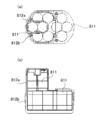
- FIGS. 12 (a) and 12 (b) a configuration is adopted in which the battery holder that houses the battery cell 811 is divided into a plurality of parts and these battery holders 812a and 812b are connected to each other.
- the width of the battery holder is defined by the length of the battery cell
- the size of the battery pack is limited to almost an integral multiple of the battery cell.
- the size of the battery pack is determined by the installation space prepared on the driving device side, it is not necessarily an integral multiple of the length of the battery cell, and the required number of battery cells are accommodated in the given space. It becomes a foot pad on the top.
- the battery holder 812a and the battery holder 812b are connected to constitute the battery holder.
- the joint area is small, if an excessive load is applied, the load is concentrated on the joint and there is a possibility of damage. Is done.
- battery packs that are intended for outdoor use may be affected by external loads such as falls, and such external forces can cause distortion and twisting of the battery pack.
- external loads such as falls, and such external forces can cause distortion and twisting of the battery pack.
- the possibility of breakage is also considered.
- the present invention has been made in view of such conventional problems.
- SUMMARY OF THE INVENTION The main object of the present invention is to provide a battery pack that allows a more flexible design that does not define the size of the battery pack as an integral multiple of the length of the battery cell, and that has a structurally increased strength. is there.
- a battery pack according to the first aspect of the present invention includes a plurality of rechargeable secondary battery cells extended in one direction, and some of the plurality of secondary battery cells.
- the first sub-holder that can be stored while being held in a posture in which the extension direction faces the first direction, and the remaining several of the plurality of secondary battery cells, the extension direction being the second direction
- a secondary sub-holder that can be stored while being held in a facing position, and the secondary battery cell stored in the first sub-holder and the secondary battery cell stored in the second sub-holder are connected in series and / or in parallel.
- the first sub-holder has an outer shape formed in a block shape, and one surface constituting the block shape serves as a first joint surface for joining the second sub-holder, and the second sub-holder Is shaped like a block In addition, one surface constituting the block shape is used as a second joining surface for joining the first sub-holder, and the first and second sub-holders have the first direction and the second direction. In a crossing posture, the first joint surface of the first sub-holder and the second joint surface of the second sub-holder are connected, and the first joint surface and the second joint surface are formed equally.
- the first sub holder and the second sub holder are not connected in the same posture, but the first sub holder and the second sub holder are connected in a posture in which the stored secondary battery cells intersect,
- a flexible arrangement independent of the length of the battery cell is possible, and the battery cell can be efficiently arranged in a given space.
- the battery pack is connected to the first joint surface of the first sub holder and the second joint surface of the second sub holder in a posture in which a plurality of stored secondary battery cells intersect with each other. The effect of twisting can be reduced.
- “equal to the first joint surface and the second joint surface” does not mean that the first joint surface and the second joint surface completely coincide with each other.
- the number of stacked layers, and the like it is used in the meaning of about 80% or more which allows a slight difference in shape.
- the first joining surface obtained by adding the substrate holder 19A to the first subholder 24A is configured to coincide with the second joining surface of the second subholder 25A is also described above.
- the first joint surface and the second joint surface are equally included.
- the first sub-holder and the second sub-holder are connected so that the first direction and the second direction are substantially orthogonal to each other.
- the battery pack can be configured by mixing the battery cells vertically and horizontally, and the arrangement direction of the battery cells in the battery pack can be freely set, thus enabling efficient arrangement.
- the first sub-holder and the second sub-holder have different configurations of secondary battery cells to be stored.
- the battery pack can be configured by mixing the vertical and horizontal placement of the secondary battery cells, and the arrangement direction of the secondary battery cells in the battery pack can be freely set, so that efficient arrangement is possible.
- the first sub-holder is divided into a first divided holder and a second divided holder in the longitudinal direction of the secondary battery cell
- a second sub holder is divided into a third divided holder and a fourth divided holder in the longitudinal direction of the secondary battery cell
- the first divided holder and the second divided holder are connected to the second sub holder.
- a first fitting piece and a second fitting piece as a part, and the third split holder includes a first fitting hole and a second fitting hole as a connecting part with the first sub-holder, The sub holder and the second sub holder are connected.
- a 1st sub holder and a 2nd sub holder can carry out the surface connection reliably, and can hold
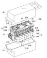
- FIG. 3 is a perspective view of a battery pack in which a first exterior battery case and a second exterior battery case according to Embodiment 1 are separated.
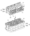
- FIG. It is the perspective view which showed the state which removed the circuit board, the lead board, etc. from the battery pack of FIG.
- FIG. 10 is a schematic perspective view of a battery pack according to Modification 1.
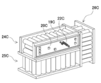
- FIG. 12 is a schematic perspective view of a battery pack according to Modification 2.
- FIG. 12 is a schematic perspective view of a battery pack according to Modification 3.
- FIG. (A) of the conventional battery pack is a top view, (b) is sectional drawing.
- each element constituting the present invention may be configured such that a plurality of elements are constituted by the same member and the plurality of elements are shared by one member, and conversely, the function of one member is constituted by a plurality of members. It can also be realized by sharing.
- the contents described in some examples and embodiments may be used in other examples and embodiments.
- the battery pack according to Embodiment 1 can be applied to a power supply device that can be used as a power supply for an assist bicycle, for example.
- a plurality of secondary battery cells are connected and connected in series and / or in parallel to increase output, and the plurality of secondary battery cells are accommodated in a sub-holder,
- the sub-holder is connected and adjusted to the voltage and power required by the driving device driven by the battery pack.
- it can be used as a power source for an electric wheelchair used in an intractable treatment ward such as a hospital or a handle type electric wheelchair used by a user who is difficult to walk for a long time by an elderly person.
- the battery pack according to Embodiment 1 first divides the battery pack, reduces the number of secondary battery cells housed in one battery pack, and connects a plurality of sub-holders.
- stacking can suppress the situation where the heat dissipation of the center vicinity of a secondary battery cell is reduced relatively.
- the battery pack is composed of one rectangular parallelepiped battery holder. Become. Therefore, the battery pack according to Embodiment 1 divides the battery holder into sub-holders, reduces the number of secondary battery cells stored in each sub-holder, and connects a plurality of sub-holders. Further, the plurality of sub-holders are connected so that the accommodated secondary battery cells intersect with each other to form a battery pack. Thereby, the battery pack which crossed the secondary battery cell can be made into a structure which cannot make distortion and twisting passive. (Embodiment 1)
- FIG. 1 shows an external perspective view of a battery pack 100 in which a first outer case and a second outer case are separated.
- the battery pack 100 is insulated and protected by a first outer case 30 and a second outer case 31.
- the battery pack 100 combines the first sub-holder 12 and the second sub-holder 13, and is integrated with the input / output terminal 23, the circuit board 20, a plurality of differently shaped lead plates 21A, lead plates 21B, and the like.
- the circuit board 20 is provided with an LED group 22 as an indicator for displaying the remaining battery level. Further, the voltage, current, temperature, etc. in the battery pack 100 are monitored by a control IC or the like mounted on the circuit board 20.
- the circuit board 20 is housed in the board holder 19 and insulated from the secondary battery cell 11.
- the substrate holder 19 is provided above the first sub-holder 12.
- the lead plate 21 ⁇ / b> A and the lead plate 21 ⁇ / b> B connect the secondary battery cells 11 in series and / or in parallel, and energize the input / output terminals 23 and the circuit board 20.
- FIG. 2 is a perspective view in which the input terminal 23, the circuit board 20, the lead plate 21A and the like are removed from FIG. 1 for the sake of explanation, and only the first sub-holder 12, the second sub-holder 13, and the plurality of secondary battery cells 11 are combined.
- each of the first sub-holder 12 and the second sub-holder 13 has a plurality of battery storage portions 14 for storing the secondary battery cells 11 in a mutually parallel posture.
- Each battery storage unit 14 stores a secondary battery cell 11.
- the 1st subholder 12 and the 2nd subholder 13 are connected with the attitude
- the secondary battery cells 11 housed in the first sub-holder 12 and the second sub-holder 13 are not in a parallel posture to each other, and the secondary battery cells 11 are held in a posture substantially orthogonal to each other.
- the size and shape of the battery holder obtained by connecting the first sub-holder 12 and the second sub-holder 13 can be set more flexibly. That is, in the conventional method in which the battery cells are connected so as to have the same posture, the size of the battery holder that stores the battery cells is an integral multiple of the length and diameter of the battery cells. In contrast, the first sub-holder 12 and the second sub-holder 13 are not connected so that the secondary battery cells 11 have the same posture, but the first sub-holder 12 in a posture in which the secondary battery cells 11 to be stored intersect. By connecting the second sub-holder 13 and the second sub-holder 13, it becomes possible to set a more flexible size that is not affected by the length or outer diameter of the secondary battery cell 11, leaving the conventional restrictions. The secondary battery cells 11 can be efficiently arranged in the space.
- the battery pack 100 can be configured by mixing the vertical placement and the horizontal placement of the secondary battery cells 11, and the arrangement direction of the secondary battery cells 11 in the battery pack 100 can be freely set, so that efficient arrangement is possible. It becomes.
- the battery pack 100 is divided into the first sub-holder 12 and the second sub-holder 13, which reduces the number of secondary battery cells 11 stacked, and the heat dissipation near the center of the stack relatively deteriorates. Can be reduced.
- the secondary battery cell 11 housed inside has a configuration in which the first sub-holder 12 and the second sub-holder 13 are substantially orthogonal to each other.
- the joint surface where the first sub-holder 12 and the second sub-holder 13 are joined to each other has about 80% or more of the side surface of each of the sub-holders on which the joint surface is provided and is surface-coupled. .
- the first sub-holder 12 and the second sub-holder 13 have a configuration in which a plurality of secondary battery cells 11 are substantially orthogonal to each other and are connected to each other in a plane connection, and disperse energy of torsion and strain due to a load such as an external impact. Can do.
- the first sub-holder 12 and the second sub-holder 13 are preferably made of a resin such as polypropylene having excellent insulating properties. To do.
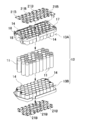
- FIG. 3 is a perspective view of a state in which the first sub-holder 12 and the second sub-holder 13 are separated and a plurality of secondary battery cells 11 are accommodated in each battery accommodating portion 14.
- the lower end surface of the first sub-holder 12 has a first joint surface 27 for connecting to the second sub-holder 13, and the second joint for connecting to the first sub-holder 12 is connected to the upper end surface of the second sub-holder 13.
- a surface 28 is provided.
- the first sub-holder 12 and the second sub-holder 13 have a different number of battery storage portions 14 and different numbers of stacked layers.
- 28 secondary battery cells 11 are stacked, and the number of stacked layers in the vertical direction is three.
- the battery pack 100 can be configured not to be proportional to the length of the secondary battery cell 11. (Sub holder)
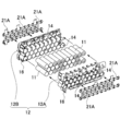
- FIG. 4 shows an exploded perspective view of the first sub-holder 12.
- the first sub-holder 12 is composed of a first divided holder 12A and a second divided holder 12B, and is provided with a plurality of battery storage portions 14 for inserting a plurality of secondary battery cells 11.
- the battery storage portion 14 has a shape that can store about 1 ⁇ 2 of the longitudinal direction of the secondary battery cell 11.
- the secondary battery cell 11 covers the whole longitudinal direction inside the battery storage part 14 of 12 A of 1st division holders, and the 2nd division holder 12B, and is further insulated and protected.
- the first sub-holder 12 in the first embodiment connects the seven secondary battery cells 11 accommodated in parallel by a plurality of lead plates 21A, and the secondary battery cells 11 connected in parallel. Are connected in series in four stages, and 28 secondary battery cells 11 are arranged.
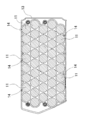
- FIG. 5 is a cross-sectional view of the joint surface between the first divided holder 12A and the second divided holder 12B.
- the battery storage portions 14 adjacent to each other in the horizontal direction are arranged apart from each other, while in the vertical direction they are offset. Is arranged.
- the temperature in the vicinity of the center of the first sub-holder 12 in this figure can suppress a situation in which heat dissipation is relatively reduced by reducing the number of vertically stacked stages to three.
- the arrangement of the battery storage portion 14 is not limited to an offset shape, and may be a grid lattice shape.
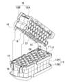
- FIG. 6 shows an exploded perspective view of the second sub-holder 13.
- the second sub holder 13 has a third divided holder 13A and a fourth divided holder 13B, and a plurality of batteries for inserting a plurality of secondary battery cells 11 in the same manner as the first sub holder 12.
- a storage unit 14 is provided. Similar to the first sub-holder 12, the secondary battery cell 11 covers the entire battery storage portion 14 of the second sub-holder 13 in the longitudinal direction, and is further insulated and protected.
- the second sub-holder 13 in the first embodiment connects the seven secondary battery cells 11 accommodated in parallel by the plurality of lead plates 21B, and the secondary battery cells 11 connected in parallel. Are connected in series in six stages, and 42 secondary battery cells 11 are arranged.
- FIG. 7 is a cross-sectional view of the joint surface between the third divided holder 13A and the fourth divided holder 13B.
- the third divided holder 13A and the fourth divided holder 13B are also arranged with the battery storage portions 14 adjacent to each other in the horizontal direction apart from each other in the same manner as the configuration of the first sub-holder 12, while offset in the vertical direction. Arranged.
- FIG. 8 shows a perspective view relating to the connection between the first sub-holder 12 and the second sub-holder 13.
- the first sub-holder 12 is provided with a first fitting piece 15 and a second fitting piece 16 on the first divided holder 12A and the second divided holder 12B on the surface side of the first joining surface 27, respectively.
- the third split holder 13 ⁇ / b> A of the second sub-holder 13 is provided with two first fitting holes 17 and two second fitting holes 18 on the surface side of the second joint surface 28.
- the connection method of the 1st sub holder 12 and the 2nd sub holder 13 is the 1st fitting hole 17 in which the 1st fitting piece 15 provided in the 1st sub holder 12 is provided also in the 2nd sub holder 13 first.
- the second fitting piece 16 provided in the first sub holder 12 is inserted into the second fitting hole 18 provided in the second sub holder 13, and the first sub holder 12 and the second sub holder 13 are integrally structured.
- the protruding end portion of the second fitting piece 16 has a bowl shape, and is fixed to the lower end wall of the opening hole of the second fitting hole 18 by the bowl shape.
- the first sub holder 12 and the second sub holder 13 are connected and electrically connected in series.
- the battery pack 100 has seven secondary battery cells 11 connected in parallel, ten connected secondary battery cells 11 connected in series, and 70 secondary battery cells 11 arranged and configured. ing.
- the number, arrangement, connection method, and number of sub-holders of the secondary battery cells 11 of the first sub-holder 12 and the second sub-holder 13 are not limited to this, and can be changed depending on the required voltage and output capacity. Needless to say. (Secondary battery cell 11)
- the secondary battery cell 11 is a cylindrical lithium ion secondary battery (Li-ion).
- the secondary battery cell 11 is not specified as a lithium ion secondary battery.
- the secondary battery cell 11 may be any battery that can be charged, such as a nickel metal hydride battery (NiCd) or a nickel cadmium battery (Ni-MH).
- NiCd nickel metal hydride battery
- Ni-MH nickel cadmium battery
- a cylindrical battery having a cylindrical outer can is used, but it goes without saying that a rectangular battery may be used.
- the present invention does not limit the arrangement position of the circuit board to such a configuration, and may be arranged on the side surface of the first sub-holder, for example.
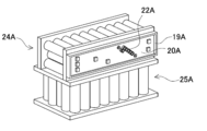
- an LED group 22A is formed on the side surface of the first subholder 24A using a step formed at the joint portion between the first subholder 24A and the second subholder 25A.
- a board holder 19A in which the provided circuit board 20A is stored is installed.
- the battery pack 100 can further reduce the height in the vertical direction and can be downsized. In this way, the arrangement of each member is left to the degree of design freedom.
- the number of sub-holders is not limited to two, and may be three or more.
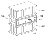
- the structure divided into three sub-holders is shown in the schematic perspective view of FIG.
- the first sub-holder 24B, the second sub-holder 25B, and the third sub-holder 26B are connected.
- a board holder 19B that houses a circuit board 20B including the LED group 22B is installed.
- the substrate holder 19B and the like are not limited to this position. Thereby, more electric power capacity can be provided.
- it can be set as the battery pack 100 made into the voltage and electric power which a drive device or electric equipment utilized requires.
- FIG. 11 is a schematic perspective view of a battery pack according to the third modification.
- the third sub-holder 26C is coupled to the short side surfaces of the first sub-holder 24C and the second sub-holder 25C.
- the secondary battery cell 11 accommodated in the third sub-holder 26C has a posture orthogonal to the secondary battery cell 11 accommodated in the first sub-holder 24C and the second sub-holder 25C.
- a substrate holder 19C that houses a circuit board 20C including an LED group 22C is installed on the side surface side of the first sub-holder 24C.
- the substrate holder 19C and the like are not limited to this position.
- the battery pack 100 can increase the power capacity and attenuate the distortion and twisting energy caused by an external impact. Due to this effect, the battery pack 100 can reduce the possibility of breakage and structurally increase the strength.
- the battery pack according to the present invention can be suitably used as a power supply device for an assist bicycle.
- these battery packs are mainly mounted on electric vehicles and used to supply power to driving motors, for example, as power sources for electric motorcycles, assist bicycles, electric wheelchairs, electric tricycles, electric carts, handle type electric wheelchairs, etc. used.
- the present invention does not specify the application of the battery pack, and can also be used as a power source for various electric devices used outdoors such as electric tools.
Landscapes
- Chemical & Material Sciences (AREA)
- Chemical Kinetics & Catalysis (AREA)
- Electrochemistry (AREA)
- General Chemical & Material Sciences (AREA)
- Engineering & Computer Science (AREA)
- Microelectronics & Electronic Packaging (AREA)
- Manufacturing & Machinery (AREA)
- Battery Mounting, Suspending (AREA)
Abstract
【課題】電池パックのサイズを電池セルの長さの整数倍に規定されない、より柔軟性の高い設計を可能とし、さらに構造的に衝撃からくる荷重の影響を低減できるようにする。 【解決手段】この電池パック100は、第一サブホルダ12及び第二サブホルダ13を組合せ、入出力端子23、回路基板20、複数で異なる形状のリード板21A及びリード板21B等と一体化させている。この構成により、第一サブホルダ12と第二サブホルダ13とを同じ姿勢で連結するのでなく、収納される二次電池セル11が交差する姿勢で第一サブホルダ12と第二サブホルダ13とを連結することで、従来のように二次電池セル11の長さに左右されない、柔軟な配置が可能となり、与えられたスペース内に二次電池セル11を効率よく配置できるようになる。
Description
本発明は、複数の充電可能な二次電池を収納した電池パックに関し、例えばアシスト自転車用の電源等に利用可能な電源装置に関する。
多数の二次電池を直列及び/又は並列に接続した電池パックが、アシスト自転車の動力源などに利用されている。近年の電池パックの出力向上、容量増量の要求に従って、使用する電池セルの数も増える傾向にある一方で、電池パックの外観の小型化、薄型化が求められている。このため、限られた空間内にいかにして多くの電池パックを配置するかが重要となる。
その一方では、電池パックを長期に渡って安定して使用可能とするため、電池セルの放熱性を向上させることも求められている。しかしながら使用する電池セルの数が多くなる程、特に電池パックの中央付近に配置された電池セルは、周囲を電池セルに囲まれているため放熱性が相対的に悪くなり、この状態は電池セルの使用本数が多いほど顕著となる。
そこで、図12(a)、(b)に示すように電池セル811を収納する電池ホルダを複数に分割して、これらの電池ホルダ812a、812b同士を連結する構成が採用されている。しかしながら、この構成では電池ホルダの幅が、電池セルの長さによって規定されるため、電池パックのサイズが電池セルのほぼ整数倍に制約されることとなる。一方で、電池パックのサイズは駆動する機器側で用意される設置空間によって決まるため、必ずしも電池セルの長さの整数倍とならず、与えられたスペース内に必要な本数の電池セルを収納する上での足枷となる。更に、電池ホルダ812aと電池ホルダ812bを連結させ電池ホルダを構成しているが、接合面積が狭いため過度の荷重負荷が加わった場合には、接合部に負荷が集中し破損の可能性も懸念される。
さらに、アシスト自転車等のように屋外での利用が企図される電池パックにおいては、転倒等の外因性による荷重の影響を受ける可能性があり、このような外力によって電池パックが歪みや捻れを受けて破損する可能性も考慮されるところである。
本発明は、従来のこのような問題点に鑑みてなされたものである。本発明の主な目的は、電池パックのサイズを電池セルの長さの整数倍に規定されない、より柔軟性の高い設計を可能とし、さらに構造的に強度を高めた電池パックを提供することにある。
上記の目的を達成するため、本発明の第1の側面に係る電池パックは、一方向に延長された充電可能な複数の二次電池セルと、前記複数の二次電池セルの内何本かを、前記延長方向が第一の方向を向く姿勢に保持して収納可能な第一サブホルダと、前記複数の二次電池セルの内残りの何本かを、前記延長方向が第二の方向を向く姿勢に保持して収納可能な第二サブホルダと、を備え、前記第一サブホルダに収納される二次電池セル及び前記第二サブホルダに収納される二次電池セルを直列及び/又は並列に接続して出力可能としており、前記第一サブホルダは、外形をブロック状に形成すると共に、該ブロック状を構成する一面を前記第二サブホルダと接合するための第一接合面としており、前記第二サブホルダは、外形をブロック状に形成すると共に、該ブロック状を構成する一面を前記第一サブホルダと接合するための第二接合面としており、前記第一サブホルダと前記第二サブホルダは、前記第一の方向と第二の方向とが交差する姿勢で、前記第一サブホルダの第一接合面と第二サブホルダの第二接合面とを連結しており、前記第一接合面と第二接合面とを同等に形成してなる。これにより、第一サブホルダと第二サブホルダとを同じ姿勢で連結するのでなく、収納される二次電池セルが交差する姿勢で第一サブホルダと第二サブホルダとを連結することで、従来のように電池セルの長さに左右されない、柔軟な配置が可能となり、与えられたスペース内に電池セルを効率よく配置できるようになる。更に、電池パックは、複数本の収納される二次電池セルが交差する姿勢で第一サブホルダの第一接合面と第二サブホルダの第二接合面とを接続した面連結することで、歪みや捻れの影響を軽減させることができる。ここで、「第一接合面と第二接合面とを同等に」とは、第一接合面と第二接合面とが完全に一致することを求めるものでなく、第一サブホルダや第二サブホルダに収納される二次電池セルの大きさや積層本数などに応じて、多少の形状の違いを許容する約8割以上の意味で使用する。例えば後述する図9で示すように、第一サブホルダ24Aに基板ホルダ19Aを加えた第一接合面が、第二サブホルダ25Aの第二接合面と一致するように構成するような態様も、上記「第一接合面と第二接合面とを同等に」に含む。
さらに、本発明の第2の側面に係る電池パックによれば、前記第一の方向と第二の方向とが略直交する姿勢で、前記第一サブホルダ及び第二サブホルダとが連結されている。これにより、電池セルの縦置きと横置きとを混在させて電池パックを構成でき、電池パック内での電池セルの配置方向を自由に設定でき効率の良い配置が可能となる。
さらにまた、本発明の第3の側面に係る電池パックによれば、前記第一サブホルダ及び第二サブホルダとで、収納する二次電池セルの段数が異なる構成とする。これにより、サブホルダ同士を同じ姿勢で連結しないことから、それぞれの段数を一致させる必要が無くなり、段数の制約を解除してより柔軟な電池セルの配置が実現できる。さらに、二次電池セルの縦置きと横置きとを混在させて電池パックを構成でき、電池パック内での二次電池セルの配置方向を自由に設定でき効率の良い配置が可能となる。
さらにまた、本発明の第4の側面に係る電池パックによれば、前記第一サブホルダが、前記二次電池セルの長手方向に、第一分割ホルダと、第二分割ホルダとに分割され、前記第二サブホルダが、前記二次電池セルの長手方向に、第三分割ホルダと、第四分割ホルダとに分割され、前記第一分割ホルダおよび前記第二分割ホルダが、前記第二サブホルダとの連結部として第一嵌合片及び第二嵌合片と、前記第三分割ホルダが、前記第一サブホルダとの連結部として第一嵌合孔及び第二嵌合孔と、を備え、前記第一サブホルダと前記第二サブホルダとを連結させている。これにより、第一サブホルダと第二サブホルダは、確実に面連結ができ、収納される複数の二次電池セルを交差した姿勢で保持することができる。さらに、連結に際し螺子止め等が無く、第一サブホルダと第二サブホルダを連結部にて連結させるため、組立工数を減少させることができる。
以下、本発明の実施の形態を図面に基づいて説明する。ただし、以下に示す実施の形態は、本発明の技術思想を具体化するための電池パックを例示するものであって、本発明は電池パックを以下のものに特定しない。また、特許請求の範囲に示される部材を、実施例の部材に特定するものでは決してない。特に実施の形態に記載されている構成部材の寸法、材質、形状、その相対的配置等は特に特定的な記載がない限りは、本発明の範囲をそれのみに限定する趣旨ではなく、単なる説明例にすぎない。なお、各図面が示す部材の大きさや位置関係等は、説明を明確にするため誇張していることがある。さらに以下の説明において、同一の名称、符号については同一もしくは同質の部材を示しており、詳細説明を適宜省略する。さらに、本発明を構成する各要素は、複数の要素を同一の部材で構成して一の部材で複数の要素を兼用する態様としてもよいし、逆に一の部材の機能を複数の部材で分担して実現することもできる。また、一部の実施例、実施形態において説明された内容は、他の実施例、実施形態等に利用可能なものもある。
(実施の形態1)
(実施の形態1)
実施の形態1に係る電池パックは、例えばアシスト自転車用の電源等に利用可能な電源装置に適用できる。このような用途においては、複数の二次電池セルを連結して、これらを直列及び/又は並列に接続して出力を増すと共に、これら複数の二次電池セルをサブホルダに収納し、更に複数のサブホルダを連結させ、電池パックで駆動される駆動装置の必要とする電圧及び電力に調整される。さらに例えば、病院等の難治治療病棟等で利用される電動車いすや、高齢者で長時間の歩行が困難なユーザに利用されるハンドル型電動車いす等の電源としても利用できる。
このような大容量の電池パックを構成する上で、例えば7本の並列で10組の直列とした計70本の円柱形の二次電池セルを、各二次電池セルの長手方向に7×10本を積層する場合を仮定してみる。この場合、電池パックの中央付近に配置された二次電池セルは、周囲を多数の二次電池セルに囲まれる構成となるため、放熱性が相対的に悪くなる。そこで実施の形態1に係る電池パックは、まず電池パックを分割し、一の電池パックに収納される二次電池セルの本数を減少させると共に、複数のサブホルダを連結する。このようにして積層本数を減少したサブホルダは、二次電池セルの中央付近の放熱性が相対的に低減される事態を抑制できる。
さらに、各二次電池セルの長手方向に7×10本を積層した電池パックでは、一つの直方体状の電池ホルダから構成されるため、外部からの衝撃による歪みや捻れを受動しやすい構造体となる。そこで実施の形態1に係る電池パックは、電池ホルダをサブホルダに分割し、各サブホルダに収納される二次電池セルの本数を減少させると共に、複数のサブホルダを連結する。更にその複数のサブホルダは、収納された二次電池セルが互いに交差する姿勢となるように連結されて、電池パックを構成する。これにより、二次電池セルを交差させた電池パックは、歪みや捻れを受動し難い構造体とすることできる。
(実施の形態1)
(実施の形態1)
ここで図1~図8に基づいて、実施形態に係る電池パック100を示す。まず図1は、第一外装ケース及び第二外装ケースを分離した電池パック100の外観斜視図を示す。この電池パック100は、第一外装ケース30及び第二外装ケース31で絶縁保護されている。さらに、電池パック100は、第一サブホルダ12及び第二サブホルダ13を組み合わせ、入出力端子23、回路基板20、複数の異なる形状のリード板21A及びリード板21B等と一体化させている。ここで回路基板20には、電池残量を表示させるインジケーターとしてLED群22を設けている。また回路基板20に実装された制御用IC等により電池パック100における電圧、電流及び温度等の監視している。この回路基板20は、基板ホルダ19に収納されて、二次電池セル11と絶縁されている。基板ホルダ19は、第一サブホルダ12の上方に設けられている。さらに、リード板21A及びリード板21Bは、各二次電池セル11を直列及び/又は並列に接続し、入出力端子23及び回路基板20に通電している。
さらに図2は、説明のため図1より入力端子23、回路基板20及びリード板21A等を外し、第一サブホルダ12、第二サブホルダ13及び複数の二次電池セル11のみの組み合わせとした斜視図である。ここで第一サブホルダ12及び第二サブホルダ13には、それぞれ二次電池セル11を互いに平行姿勢で収納するための複数の電池収納部14を有する。各電池収納部14には、二次電池セル11が収納されている。また第一サブホルダ12及び第二サブホルダ13は、互いに略直交する姿勢で連結される。この結果、第一サブホルダ12及び第二サブホルダ13に各々収納される二次電池セル11が、互いに平行な姿勢とならず、二次電池セル11同士が互いにほぼ直交する姿勢に保持される。
この構成により、第一サブホルダ12及び第二サブホルダ13を連結して得られる電池ホルダの寸法及び形状を、より柔軟に設定できる。すなわち、従来のように電池セルが同じ姿勢となるように連結する方式では、電池セルを収納する電池ホルダの寸法が、電池セルの長さや径の整数倍となっていた。これに対して、二次電池セル11が同じ姿勢となるように第一サブホルダ12と第二サブホルダ13とを連結するのでなく、収納される二次電池セル11が交差する姿勢で第一サブホルダ12と第二サブホルダ13とを連結することで、従来のような制約を離れて、二次電池セル11の長さや外径に左右されない、より柔軟なサイズに設定することが可能となり、与えられたスペース内に二次電池セル11を効率よく配置できるようになる。
さらに、二次電池セル11の縦置きと横置きとを混在させて電池パック100を構成でき、電池パック100内での二次電池セル11の配置方向を自由に設定でき効率の良い配置が可能となる。
さらにまた、電池パック100が第一サブホルダ12と第二サブホルダ13とに分割され、これにより積層される二次電池セル11の数が減少し、積層中央付近の放熱性が相対的に悪くなることを低減させることができる。
さらにまた、内部に収納される二次電池セル11は、第一サブホルダ12と第二サブホルダ13とで略直交する構成となる。ただ、第一サブホルダ12と第二サブホルダ13との接合面の連結した部分は、接合面の面積が小さいと歪みの影響を受動し易く破損の可能性もある。そのため好ましくは、第一サブホルダ12と第二サブホルダ13とが互いに接合される接合面は、その接合面が設けられているそれぞれのサブホルダの側面の約8割以上を有し、面連結している。これにより第一サブホルダ12と第二サブホルダ13は、複数の二次電池セル11が略直交を成し、更に面連結とする構成となり、外部衝撃等の荷重によるねじれや歪みのエネルギーを分散することができる。
実施の形態1に係る第一サブホルダ12及び第二サブホルダ13は、数多くの二次電池セル11を収納し、正極と負極とが隣接するため、好ましくは絶縁性に優れたポリプロピレン等の樹脂製とする。
図3は、第一サブホルダ12及び第二サブホルダ13を分離し、各電池収納部14に複数の二次電池セル11が収納された状態の斜視図である。第一サブホルダ12の下端面には、第二サブホルダ13と連結するための第一接合面27を有し、第二サブホルダ13の上端面には、第一サブホルダ12と連結するための第二接合面28を有している。この図のように第一サブホルダ12と第二サブホルダ13は、電池収納部14の数が違い、積層段数を異なる構成としている。この実施の形態1に係る第一サブホルダ12には、28本の二次電池セル11を積層し、垂直方向での積層段数を3段としている。更に、第二サブホルダ13には、42本の二次電池セル11を積層し、幅が狭い水平方向での積層段数を5段としている。この構成によって、第一サブホルダ12の垂直方向の長さを、使用される二次電池セル11の長さよりも短くできる。この結果、電池パック100を、二次電池セル11の長さに比例しない構成とすることができる。
(サブホルダ)
(サブホルダ)
図4に、第一サブホルダ12の分解斜視図を示す。この図に示すように、第一サブホルダ12は、第一分割ホルダ12A及び第二分割ホルダ12Bで構成され、複数の二次電池セル11を挿入するための複数の電池収納部14を設けている。この電池収納部14は、二次電池セル11の長手方向の約1/2を収納できる形状を成している。これにより、二次電池セル11は、第一分割ホルダ12Aと第二分割ホルダ12Bの電池収納部14の内部に長手方向全体を被覆し、更に絶縁保護される。
さらに、この実施の形態1での第一サブホルダ12は、複数のリード板21Aにて、収納されている二次電池セル11を7本並列に接続すると共に、並列接続された二次電池セル11を4段直列に接続し、二次電池セル11を28本配置する構成としている。
さらにまた図5は、第一分割ホルダ12Aと第二分割ホルダ12Bとの接合面における断面図である。この図に示すように、この実施の形態1での第一分割ホルダ12A及び第二分割ホルダ12Bは、水平方向において隣り合う電池収納部14を離間させて配置し、一方垂直方向においてはオフセット状に配置している。この図の第一サブホルダ12の中央付近の温度は、垂直方向の積層される段数が3段と少なくしたことで、放熱性が相対的に低減される事態を抑制できる。更に、このように物理的に電池収納部14を離間させることで、電池収納部14に収納される二次電池セル11が発熱しても、隣接する二次電池セル11への影響を低減できる。ただ、電池収納部14の配置は、オフセット状には限定するものではなく、碁盤格子状としてもよいことは言うまでもない。
次に図6は第二サブホルダ13の分解斜視図を示す。この図に示すように、第二サブホルダ13は、第三分割ホルダ13A及び第四分割ホルダ13Bを有し、第一サブホルダ12同様に、複数の二次電池セル11を挿入するための複数の電池収納部14を設けている。二次電池セル11は、第一サブホルダ12同様に第二サブホルダ13の電池収納部14の内部に長手方向全体を被覆し、更に絶縁保護される。
さらに、この実施の形態1での第二サブホルダ13は、複数のリード板21Bにて、収納されている二次電池セル11を7本並列に接続すると共に、並列接続された二次電池セル11を6段直列に接続し、二次電池セル11を42本配置する構成としている。
さらにまた図7は、第三分割ホルダ13Aと第四分割ホルダ13Bとの接合面における断面図である。この図のように、第三分割ホルダ13A及び第四分割ホルダ13Bも、第一サブホルダ12の構成と同じく、水平方向において隣り合う電池収納部14を離間させて配置し、一方垂直方向においてはオフセット状に配置している。
さらにまた、図8は、第一サブホルダ12と第二サブホルダ13との連結に係る斜視図を示している。第一サブホルダ12は、第一接合面27の面側に第一分割ホルダ12A及び第二分割ホルダ12Bにそれぞれ第一嵌合片15及び第二嵌合片16を設けている。更に第二サブホルダ13の第三分割ホルダ13Aには、第二接合面28の面側に第一嵌合孔17及び第二嵌合孔18を各2カ所を設けている。これにより、第一サブホルダ12と第二サブホルダ13の連結方法は、まず第一サブホルダ12に設けている第一嵌合片15が、第二サブホルダ13にも設けられている第一嵌合孔17に挿入される。その後、第一サブホルダ12に設けられている第二嵌合片16が、第二サブホルダ13に設けられた第二嵌合孔18に挿入され、第一サブホルダ12と第二サブホルダ13とを一体構造とする。ここで、突出した第二嵌合片16の先端部は鉤状の形状を有し、その鉤状により第二嵌合孔18の開口孔の下端壁に固定される。これにより、第一サブホルダ12と第二サブホルダ13は、第一接合面27と第二接合面28により確実に面連結でき、収納される複数の二次電池セル11を交差した姿勢で保持することができる。さらにこれにより一度の組み上げ作業で連結ができるので、作業効率を向上させることができる。
この実施の形態1での電池パック100は、第一サブホルダ12と第二サブホルダ13が連結され、電気的に直列に接続されている。これにより電池パック100は、二次電池セル11を7本並列に接続する共に、並列接続された二次電池セル11を10段直列に接続し、二次電池セル11を70本配置し構成している。第一サブホルダ12と第二サブホルダ13の二次電池セル11の数、配列、接続方法及びサブホルダの数に関しては、これに限られるものではなく、必要とされる電圧や出力容量によって変更が可能なことは言うまでもない。
(二次電池セル11)
(二次電池セル11)
この実施の形態1に係る二次電池セル11は、円柱状のリチウムイオン二次電池(Li-ion)としいる。ただ、二次電池セル11は、リチウムイオン二次電池には特定しない。例えば二次電池セル11を、ニッケル水素電池(NiCd)やニッケルカドミウム電池(Ni-MH)等の充電できる全ての電池とすることもできる。またこの例では、外装缶を円筒形とする円筒形電池を用いているが、角形電池を使用してもよいことは言うまでもない。
(変形例)
(変形例)
以上説明した実施の形態1では、回路基板20を第一サブホルダ12の上方に設置する例を説明した。ただ、本発明は回路基板の配置位置をこのような構成に限定するものではなく、例えば第一サブホルダの側面に配置することもできる。一例として、図9の概略斜視図で示す変形例1では、第一サブホルダ24Aと第二サブホルダ25Aとの接合部分にできた段差を利用し、第一サブホルダ24Aの側面側に、LED群22Aを備えた回路基板20Aが収納された基板ホルダ19Aを設置している。これにより、電池パック100は、更に垂直方向の高さを低くすることができ、小型化を行うことができる。このように各部材の配置に関しては、設計の自由度に任される。
さらに実施の形態1では、電池ホルダを第一サブホルダ12と第二サブホルダ13に二分割する例を説明したが、サブホルダの数は2つに限るものでなく、3以上とすることもできる。一例として3つのサブホルダに分割する構成を変形例2として図10の概略斜視図に示す。この図に示すように変形例2では、第一サブホルダ24Bと第二サブホルダ25Bと更に第三サブホルダ26Bを連結させている。さらに変形例1と同様に第一サブホルダ24Bの側面側には、LED群22Bを備えた回路基板20Bを収納された基板ホルダ19Bを設置している。ただ、基板ホルダ19B等は、この位置に限るものではない。これにより、より多くの電力容量を備えることができる。このように、利用される駆動装置又は電気機器が必要とする電圧及び電力とした電池パック100とすることができる。
さらにまた図11は、変形例3に係る電池パックの概略斜視図である。変形例3では、第三サブホルダ26Cを、第一サブホルダ24Cと第二サブホルダ25Cとの短側面に連結する。この第三サブホルダ26Cに収納される二次電池セル11は、第一サブホルダ24C及び第二サブホルダ25Cに収納されている二次電池セル11と直交させた姿勢とする。さらに、変形例1及び変形例2と同様に第一サブホルダ24Cの側面側には、LED群22Cを備えた回路基板20Cを収納された基板ホルダ19Cを設置している。ただ、基板ホルダ19C等はこの位置に限るものではない。これにより電池パック100は、電力容量を増すことができると共に、外部からの衝撃による歪みや捻れのエネルギーを減衰させることができる。この効果により電池パック100は、破損の可能性を減少させることができ、構造的に強度を高めることができる。
本発明に係る電池パックは、アシスト自転車用の電源装置として好適に利用できる。またこれら電池パックは、主として電動の乗り物に装着されて、駆動用のモータに電力を供給する用途、例えば電動バイク、アシスト自転車、電動車椅子、電動三輪車、電動カート、ハンドル型電動車いす等の電源として使用される。ただ、本発明は電池パックの用途を特定するものではなく、電動工具等の屋外で使用される種々の電気機器用の電源として使用することもできる。
100…電池パック
11…二次電池セル
12…第一サブホルダ
12A…第一分割ホルダ
12B…第二分割ホルダ
13…第二サブホルダ
13A…第三分割ホルダ
13B…第四分割ホルダ
14…電池収納部
15…第一嵌合片
16…第二嵌合片
17…第一嵌合孔
18…第二嵌合孔
19、19A、19B、19C…基板ホルダ
20、20A、20B、20C…回路基板
21A、21B…リード板
22、22A、22B、22C…LED群
23…入出力端子
24A、24B、24C…第一サブホルダ
25A、25B、25C…第二サブホルダ
26B、26C…第三サブホルダ
27…第一接合面
28…第二接合面
30…第一外装ケース
31…第二外装ケース
811…電池セル
812a、812b…電池ホルダ
Claims (4)
- 一方向に延長された充電可能な複数の二次電池セルと、
前記複数の二次電池セルの内何本かを、前記延長方向が第一の方向を向く姿勢に保持して収納可能な第一サブホルダと、
前記複数の二次電池セルの内残りの何本かを、前記延長方向が第二の方向を向く姿勢に保持して収納可能な第二サブホルダと、
を備え、
前記第一サブホルダに収納される二次電池セル及び前記第二サブホルダに収納される二次電池セルを直列及び/又は並列に接続して出力可能としており、
前記第一サブホルダは、外形をブロック状に形成すると共に、該ブロック状を構成する一面を前記第二サブホルダと接合するための第一接合面としており、
前記第二サブホルダは、外形をブロック状に形成すると共に、該ブロック状を構成する一面を前記第一サブホルダと接合するための第二接合面としており、
前記第一サブホルダと前記第二サブホルダは、前記第一の方向と第二の方向とが交差する姿勢で、前記第一サブホルダの第一接合面と第二サブホルダの第二接合面とを連結しており、
前記第一接合面と第二接合面とを同等に形成してなることを特徴とする電池パック。 - 請求項1に記載の電池パックであって、
前記第一の方向と第二の方向とが略直交する姿勢で、前記第一サブホルダ及び第二サブホルダとが連結されてなることを特徴とする電池パック。 - 請求項1又は2に記載の電池パックであって、
前記第一サブホルダ及び第二サブホルダとで、収納する二次電池セルの段数が異なることを特徴とする電池パック。 - 請求項1から5のいずれかの一に記載の電池パックであって、
前記第一サブホルダが、前記二次電池セルの長手方向に、第一分割ホルダと、第二分割ホルダとに分割され、
前記第二サブホルダが、前記二次電池セルの長手方向に、第三分割ホルダと、第四分割ホルダとに分割され、
前記第一分割ホルダおよび前記第二分割ホルダが、前記第二サブホルダとの連結部として第一嵌合片及び第二嵌合片と、
前記第三分割ホルダが、前記第一サブホルダとの連結部として第一嵌合孔及び第二嵌合孔と、
を備え、前記第一サブホルダと前記第二サブホルダとを連結させること特徴とする電池パック。
Applications Claiming Priority (2)
| Application Number | Priority Date | Filing Date | Title |
|---|---|---|---|
| JP2011105584A JP2014139867A (ja) | 2011-05-10 | 2011-05-10 | 電池パック |
| JP2011-105584 | 2011-05-10 |
Publications (1)
| Publication Number | Publication Date |
|---|---|
| WO2012153633A1 true WO2012153633A1 (ja) | 2012-11-15 |
Family
ID=47139118
Family Applications (1)
| Application Number | Title | Priority Date | Filing Date |
|---|---|---|---|
| PCT/JP2012/061008 Ceased WO2012153633A1 (ja) | 2011-05-10 | 2012-04-25 | 電池パック |
Country Status (2)
| Country | Link |
|---|---|
| JP (1) | JP2014139867A (ja) |
| WO (1) | WO2012153633A1 (ja) |
Cited By (1)
| Publication number | Priority date | Publication date | Assignee | Title |
|---|---|---|---|---|
| EP3076454A4 (en) * | 2013-11-26 | 2016-11-30 | Nissan Motor | BATTERY PACK |
Families Citing this family (5)
| Publication number | Priority date | Publication date | Assignee | Title |
|---|---|---|---|---|
| MY192772A (en) * | 2014-10-31 | 2022-09-08 | Piaggio & C Spa | Rechargeable battery pack for electric or hybrid vehicles |
| KR102074250B1 (ko) * | 2015-07-22 | 2020-02-06 | 주식회사 엘지화학 | 확장 가능한 구조의 전지팩 |
| KR102074245B1 (ko) * | 2015-07-22 | 2020-02-06 | 주식회사 엘지화학 | 확장 가능한 구조의 팩 프레임 |
| KR102066913B1 (ko) * | 2015-07-23 | 2020-02-11 | 주식회사 엘지화학 | 단자 플레이트의 삽입 및 장착이 용이한 구조의 전지모듈 |
| DE102020207630A1 (de) * | 2020-06-19 | 2021-12-23 | Robert Bosch Gesellschaft mit beschränkter Haftung | Batteriemodul, Verfahren zur Herstellung eines solchen und Verwendung eines solchen |
Citations (7)
| Publication number | Priority date | Publication date | Assignee | Title |
|---|---|---|---|---|
| JPS57161769U (ja) * | 1981-07-14 | 1982-10-12 | ||
| JPS611266U (ja) * | 1984-06-11 | 1986-01-07 | オリンパス光学工業株式会社 | 乾電池を同数組複数並列に配列したストロボ等の電源電池収納装置 |
| JPH11345631A (ja) * | 1998-06-02 | 1999-12-14 | Fuji Film Celltec Kk | バッテリーパック |
| JP2000100401A (ja) * | 1998-09-22 | 2000-04-07 | Fuji Film Celltec Kk | バッテリーパック |
| JP2003077437A (ja) * | 2001-08-31 | 2003-03-14 | Matsushita Electric Works Ltd | 電池パック |
| JP2009224326A (ja) * | 2008-03-16 | 2009-10-01 | Lenovo Singapore Pte Ltd | パック内のセルの適正配置によるバッテリー・セルの破壊及び熱的カスケードの低減 |
| JP2010027501A (ja) * | 2008-07-23 | 2010-02-04 | Sanyo Electric Co Ltd | 電池組立体及びパック電池 |
-
2011
- 2011-05-10 JP JP2011105584A patent/JP2014139867A/ja not_active Withdrawn
-
2012
- 2012-04-25 WO PCT/JP2012/061008 patent/WO2012153633A1/ja not_active Ceased
Patent Citations (7)
| Publication number | Priority date | Publication date | Assignee | Title |
|---|---|---|---|---|
| JPS57161769U (ja) * | 1981-07-14 | 1982-10-12 | ||
| JPS611266U (ja) * | 1984-06-11 | 1986-01-07 | オリンパス光学工業株式会社 | 乾電池を同数組複数並列に配列したストロボ等の電源電池収納装置 |
| JPH11345631A (ja) * | 1998-06-02 | 1999-12-14 | Fuji Film Celltec Kk | バッテリーパック |
| JP2000100401A (ja) * | 1998-09-22 | 2000-04-07 | Fuji Film Celltec Kk | バッテリーパック |
| JP2003077437A (ja) * | 2001-08-31 | 2003-03-14 | Matsushita Electric Works Ltd | 電池パック |
| JP2009224326A (ja) * | 2008-03-16 | 2009-10-01 | Lenovo Singapore Pte Ltd | パック内のセルの適正配置によるバッテリー・セルの破壊及び熱的カスケードの低減 |
| JP2010027501A (ja) * | 2008-07-23 | 2010-02-04 | Sanyo Electric Co Ltd | 電池組立体及びパック電池 |
Cited By (4)
| Publication number | Priority date | Publication date | Assignee | Title |
|---|---|---|---|---|
| EP3076454A4 (en) * | 2013-11-26 | 2016-11-30 | Nissan Motor | BATTERY PACK |
| JPWO2015079496A1 (ja) * | 2013-11-26 | 2017-03-16 | 日産自動車株式会社 | 組電池 |
| KR101765024B1 (ko) | 2013-11-26 | 2017-08-03 | 닛산 지도우샤 가부시키가이샤 | 조전지 |
| US10468647B2 (en) | 2013-11-26 | 2019-11-05 | Envision Aesc Japan Ltd. | Battery pack |
Also Published As
| Publication number | Publication date |
|---|---|
| JP2014139867A (ja) | 2014-07-31 |
Similar Documents
| Publication | Publication Date | Title |
|---|---|---|
| CN208781901U (zh) | 二次电池模块以及二次电池冷却框架 | |
| JP5779657B2 (ja) | バッテリーモジュールケース | |
| JP5490516B2 (ja) | 電池パック | |
| US9005798B2 (en) | Battery pack | |
| JP5496746B2 (ja) | バッテリパック | |
| JP5323782B2 (ja) | 電池モジュール及び複数の電池モジュールを備える電池パック | |
| EP3067959B1 (en) | Battery pack including bushing for connecting end plate | |
| EP2410590B1 (en) | Battery pack | |
| EP2913864B1 (en) | Rechargeable battery pack | |
| KR102248597B1 (ko) | 배터리 팩 | |
| CN101527375B (zh) | 蓄电池组 | |
| JP2014139867A (ja) | 電池パック | |
| JP6334725B2 (ja) | レセプタクル構造の電圧センシング部材を含む電池モジュール | |
| WO2013021592A1 (ja) | 電池パック | |
| JP2012059373A (ja) | 電池パック及び電池パック用電池ホルダ | |
| KR101897822B1 (ko) | 배터리 팩 | |
| JP2019212561A (ja) | 蓄電装置及び組電池 | |
| JP2011171125A (ja) | 電池パック及びその製造方法 | |
| CN104641489B (zh) | 电池组 | |
| JP5748190B2 (ja) | 電池ユニットおよびこれを用いた電源装置 | |
| JP5142521B2 (ja) | パック電池 | |
| JP2014022238A (ja) | 電池パック | |
| JP2025169446A (ja) | 向上したエネルギー密度を有する充電式バッテリーパック | |
| JP2014022239A (ja) | 電池パック | |
| KR102008967B1 (ko) | 배터리 팩 |
Legal Events
| Date | Code | Title | Description |
|---|---|---|---|
| 121 | Ep: the epo has been informed by wipo that ep was designated in this application |
Ref document number: 12782546 Country of ref document: EP Kind code of ref document: A1 |
|
| NENP | Non-entry into the national phase |
Ref country code: DE |
|
| 122 | Ep: pct application non-entry in european phase |
Ref document number: 12782546 Country of ref document: EP Kind code of ref document: A1 |
|
| NENP | Non-entry into the national phase |
Ref country code: JP |