WO2012153614A1 - 冷却庫 - Google Patents
冷却庫 Download PDFInfo
- Publication number
- WO2012153614A1 WO2012153614A1 PCT/JP2012/060548 JP2012060548W WO2012153614A1 WO 2012153614 A1 WO2012153614 A1 WO 2012153614A1 JP 2012060548 W JP2012060548 W JP 2012060548W WO 2012153614 A1 WO2012153614 A1 WO 2012153614A1
- Authority
- WO
- WIPO (PCT)
- Prior art keywords
- cooling chamber
- fan
- container
- air
- region
- Prior art date
- Legal status (The legal status is an assumption and is not a legal conclusion. Google has not performed a legal analysis and makes no representation as to the accuracy of the status listed.)
- Ceased
Links
Images

Classifications
-
- F—MECHANICAL ENGINEERING; LIGHTING; HEATING; WEAPONS; BLASTING
- F25—REFRIGERATION OR COOLING; COMBINED HEATING AND REFRIGERATION SYSTEMS; HEAT PUMP SYSTEMS; MANUFACTURE OR STORAGE OF ICE; LIQUEFACTION SOLIDIFICATION OF GASES
- F25D—REFRIGERATORS; COLD ROOMS; ICE-BOXES; COOLING OR FREEZING APPARATUS NOT OTHERWISE PROVIDED FOR
- F25D31/00—Other cooling or freezing apparatus
- F25D31/006—Other cooling or freezing apparatus specially adapted for cooling receptacles, e.g. tanks
- F25D31/007—Bottles or cans
-
- F—MECHANICAL ENGINEERING; LIGHTING; HEATING; WEAPONS; BLASTING
- F25—REFRIGERATION OR COOLING; COMBINED HEATING AND REFRIGERATION SYSTEMS; HEAT PUMP SYSTEMS; MANUFACTURE OR STORAGE OF ICE; LIQUEFACTION SOLIDIFICATION OF GASES
- F25D—REFRIGERATORS; COLD ROOMS; ICE-BOXES; COOLING OR FREEZING APPARATUS NOT OTHERWISE PROVIDED FOR
- F25D11/00—Self-contained movable devices, e.g. domestic refrigerators
-
- F—MECHANICAL ENGINEERING; LIGHTING; HEATING; WEAPONS; BLASTING
- F25—REFRIGERATION OR COOLING; COMBINED HEATING AND REFRIGERATION SYSTEMS; HEAT PUMP SYSTEMS; MANUFACTURE OR STORAGE OF ICE; LIQUEFACTION SOLIDIFICATION OF GASES
- F25D—REFRIGERATORS; COLD ROOMS; ICE-BOXES; COOLING OR FREEZING APPARATUS NOT OTHERWISE PROVIDED FOR
- F25D17/00—Arrangements for circulating cooling fluids; Arrangements for circulating gas, e.g. air, within refrigerated spaces
- F25D17/04—Arrangements for circulating cooling fluids; Arrangements for circulating gas, e.g. air, within refrigerated spaces for circulating air, e.g. by convection
- F25D17/06—Arrangements for circulating cooling fluids; Arrangements for circulating gas, e.g. air, within refrigerated spaces for circulating air, e.g. by convection by forced circulation
-
- F—MECHANICAL ENGINEERING; LIGHTING; HEATING; WEAPONS; BLASTING
- F25—REFRIGERATION OR COOLING; COMBINED HEATING AND REFRIGERATION SYSTEMS; HEAT PUMP SYSTEMS; MANUFACTURE OR STORAGE OF ICE; LIQUEFACTION SOLIDIFICATION OF GASES
- F25D—REFRIGERATORS; COLD ROOMS; ICE-BOXES; COOLING OR FREEZING APPARATUS NOT OTHERWISE PROVIDED FOR
- F25D17/00—Arrangements for circulating cooling fluids; Arrangements for circulating gas, e.g. air, within refrigerated spaces
- F25D17/04—Arrangements for circulating cooling fluids; Arrangements for circulating gas, e.g. air, within refrigerated spaces for circulating air, e.g. by convection
- F25D17/06—Arrangements for circulating cooling fluids; Arrangements for circulating gas, e.g. air, within refrigerated spaces for circulating air, e.g. by convection by forced circulation
- F25D17/08—Arrangements for circulating cooling fluids; Arrangements for circulating gas, e.g. air, within refrigerated spaces for circulating air, e.g. by convection by forced circulation using ducts
-
- F—MECHANICAL ENGINEERING; LIGHTING; HEATING; WEAPONS; BLASTING
- F25—REFRIGERATION OR COOLING; COMBINED HEATING AND REFRIGERATION SYSTEMS; HEAT PUMP SYSTEMS; MANUFACTURE OR STORAGE OF ICE; LIQUEFACTION SOLIDIFICATION OF GASES
- F25D—REFRIGERATORS; COLD ROOMS; ICE-BOXES; COOLING OR FREEZING APPARATUS NOT OTHERWISE PROVIDED FOR
- F25D23/00—General constructional features
- F25D23/06—Walls
- F25D23/061—Walls with conduit means
-
- F—MECHANICAL ENGINEERING; LIGHTING; HEATING; WEAPONS; BLASTING
- F25—REFRIGERATION OR COOLING; COMBINED HEATING AND REFRIGERATION SYSTEMS; HEAT PUMP SYSTEMS; MANUFACTURE OR STORAGE OF ICE; LIQUEFACTION SOLIDIFICATION OF GASES
- F25D—REFRIGERATORS; COLD ROOMS; ICE-BOXES; COOLING OR FREEZING APPARATUS NOT OTHERWISE PROVIDED FOR
- F25D2317/00—Details or arrangements for circulating cooling fluids; Details or arrangements for circulating gas, e.g. air, within refrigerated spaces, not provided for in other groups of this subclass
- F25D2317/06—Details or arrangements for circulating cooling fluids; Details or arrangements for circulating gas, e.g. air, within refrigerated spaces, not provided for in other groups of this subclass with forced air circulation
- F25D2317/063—Details or arrangements for circulating cooling fluids; Details or arrangements for circulating gas, e.g. air, within refrigerated spaces, not provided for in other groups of this subclass with forced air circulation with air guides
-
- F—MECHANICAL ENGINEERING; LIGHTING; HEATING; WEAPONS; BLASTING
- F25—REFRIGERATION OR COOLING; COMBINED HEATING AND REFRIGERATION SYSTEMS; HEAT PUMP SYSTEMS; MANUFACTURE OR STORAGE OF ICE; LIQUEFACTION SOLIDIFICATION OF GASES
- F25D—REFRIGERATORS; COLD ROOMS; ICE-BOXES; COOLING OR FREEZING APPARATUS NOT OTHERWISE PROVIDED FOR
- F25D2317/00—Details or arrangements for circulating cooling fluids; Details or arrangements for circulating gas, e.g. air, within refrigerated spaces, not provided for in other groups of this subclass
- F25D2317/06—Details or arrangements for circulating cooling fluids; Details or arrangements for circulating gas, e.g. air, within refrigerated spaces, not provided for in other groups of this subclass with forced air circulation
- F25D2317/066—Details or arrangements for circulating cooling fluids; Details or arrangements for circulating gas, e.g. air, within refrigerated spaces, not provided for in other groups of this subclass with forced air circulation characterised by the air supply
- F25D2317/0661—Details or arrangements for circulating cooling fluids; Details or arrangements for circulating gas, e.g. air, within refrigerated spaces, not provided for in other groups of this subclass with forced air circulation characterised by the air supply from the bottom
Definitions
- the present invention relates to a refrigerator for supercooling liquid beverages such as beverages containing alcohol, teas, and coffees.
- a cooling device described in Patent Document 1 As a refrigerator that can store a container in which a liquid beverage is placed at a temperature below the freezing point of the liquid and in a supercooled state in which the liquid beverage is kept unfrozen, for example, a cooling device described in Patent Document 1 is provided. Are known.
- the cooling device of Patent Document 1 has a cooler for storing a container and a control means for controlling the temperature in the cooler. And such a cooling device cools a container with the cold air in a refrigerator by controlling the temperature in a refrigerator with a control means in the state where the container was stored in a refrigerator, and the liquid drink in a container is made. Make it supercooled.
- Patent Document 1 does not disclose the configuration of the refrigerator that houses the container.
- temperature control temperature management of the liquid beverage (container) is very important. Therefore, in the cooling device of Patent Document 1 in which the configuration of the refrigerator is unknown, it is difficult to put the liquid beverage in a supercooled state.
- a commonly known refrigerator such as a refrigerator or freezer is used, the flow of cold air may be uneven, or a relatively large temperature may occur near the inner wall of the refrigerator and near the center. Therefore, the temperature in the refrigerator becomes non-uniform. Therefore, depending on the installation position of the container and the shape of the container, it becomes difficult to cool the container uniformly throughout, and the liquid beverage in the container cannot be brought into a supercooled state.
- An object of the present invention is to provide a refrigerator capable of bringing a liquid contained in a container into a supercooled state with a simple configuration.
- the present invention comprises a cooling chamber for containing a container containing a liquid, Cooling means for cooling the air in the cooling chamber; A fan provided in the lower part of the cooling chamber for circulating air; A cylindrical guide portion that is provided above the fan in the cooling chamber, protects the fan, and guides at least a part of the air blown from the fan; With the container housed in the cooling chamber, the air in the cooling chamber is circulated by the fan, whereby the container is supercooled at a temperature below the freezing point of the liquid and the liquid remains unfrozen. It is a refrigerator characterized by storing in a state.
- the lower opening of the guide portion includes the fan inside.
- the lower opening is provided so as to be inclined so that the front side portion of the cooling chamber is located above the back side portion.
- the refrigerator of the present invention it is preferable that 70 to 90% of the air blown out from the fan flows into the guide portion from the lower opening.
- the air that has not flowed into the guide portion out of the air blown from the fan is guided to the front side of the cooling chamber.
- the guide portion is inclined so that the upper opening is located on the back side of the cooling chamber with respect to the lower opening when the guide portion is viewed from the upper side. .
- the opening area of the lower opening is preferably larger than the opening area of the upper opening.
- the guide portion is a front plate, a back plate positioned on the back side of the cooling chamber with respect to the front plate, and disposed opposite to the front plate, and the front plate and the back plate.
- a pair of side plates for connecting The front plate and the back plate are provided so as to be inclined such that the upper side is located on the deeper side of the cooling chamber than the lower side, and the front plate is perpendicular to the rear plate. It is preferable that the slope is greatly inclined.
- the cooling chamber has a first region and a second region located on the back side of the first region,
- the fan and the guide section are installed in the first area;
- the container In the first region, the container is placed upright,
- the container In the second region, the container is preferably placed sideways.
- a placement unit for placing the container is provided in each of the first region and the second region.
- the guide portion is provided so as to guide air from the lower step portion to the upper step portion.
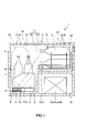
- FIG. 1 is a cross-sectional view showing a preferred embodiment of the refrigerator of the present invention.
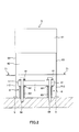
- FIG. 2 is a plan view showing a fan and a guide part included in the refrigerator shown in FIG.
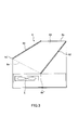
- FIG. 3 is a cross-sectional view of the guiding portion of the refrigerator shown in FIG.
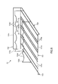
- FIG. 4 is a perspective view showing a first placement portion of the refrigerator shown in FIG.
- FIG. 5 is a perspective view showing a second placement portion of the refrigerator shown in FIG.
- FIG. 1 is a cross-sectional view showing a preferred embodiment of the refrigerator according to the present invention
- FIG. 2 is a plan view showing a fan and a guide part included in the refrigerator shown in FIG. 1
- FIG. 3 is a refrigerator shown in FIG.
- FIG. 4 is a perspective view showing a first placement portion of the cooler shown in FIG. 1
- FIG. 5 is a second view of the second placement portion of the cooler shown in FIG. It is a perspective view shown.
- the upper side in FIG. 1 is referred to as “upper”, the lower side as “lower”, the left side (door side) as “front”, and the right side as “right”.
- the cooler 1 shown in FIG. 1 includes a cooling chamber 21 on the inner side, a main body 2 having an opening on the front surface, and a door 3 that can be rotated with respect to the main body 2 and can open and close the opening. have.
- the cooler 1 includes a cooling unit 4 that cools the air in the cooling chamber 21, a fan 5 that circulates cold air (air cooled by the cooling unit 4, the same applies hereinafter) in the cooling chamber 21, and It has the induction
- Such a refrigerator 1 circulates the air (cold air) cooled by the cooling means 4 in the cooling chamber 21 by the fan 5 while the container B in which the liquid beverage L is put in the cooling chamber 21 is accommodated.
- it is a refrigerator which can preserve
- the supercooled liquid beverage L that remains unfrozen below the freezing point is instantly frozen into a sherbet when taken out of the refrigerator 1 and subjected to vibrations or poured into a cup or the like.
- the liquid beverage L to be placed in the container B is not particularly limited.
- soft drinks such as teas (oolong tea, green tea, barley tea, etc.), coffees, mineral water, sports drinks, lactic acid beverages (milk, etc.),
- alcoholic beverages such as sparkling liquor, beer, wine, sake, and shochu.
- the freezing point of the soft drink as described above is about ⁇ 9 to ⁇ 4 ° C.
- the freezing point of the alcoholic beverage is about ⁇ 15 to ⁇ 12 ° C.
- the capacity of the container B is not particularly limited, but is preferably 80 to 1000 ml, and more preferably 100 to 600 ml. By setting it as such a capacity
- the container B is not particularly limited, and may be various cans such as aluminum cans and steel cans, may be a PET bottle, or may be a bottle.
- Tmax ⁇ Tmin satisfies 0 to 0.1 ° C. or less, where Tmax is the temperature of the highest temperature portion of the liquid beverage L in the container B and Tmin is the temperature of the lowest temperature portion.
- Tmax is the temperature of the highest temperature portion of the liquid beverage L in the container B
- Tmin is the temperature of the lowest temperature portion.
- the container B may be cooled so that the temperature difference in the liquid beverage L hardly occurs.
- a relatively large temperature difference for example, about 1 to 2 ° C.
- the main body 2 has an outer wall 22 and an inner wall 23, and has a structure in which a heat insulating material 24 is filled therebetween. Further, a refrigerant pipe 41 included in the cooling means 4 is embedded in the main body 2.
- the main body 2 is provided with a machine room 25. Various machines necessary for driving the refrigerator 1 are accommodated in the machine room 25. Examples of such machinery include a power source, an evaporator 43, a compressor 44, and a condenser 45 included in the cooling unit 4.
- the inner wall 23 of the main body 2 is preferably made of a material having a high thermal conductivity (for example, a material having a thermal conductivity of 50 W / (m ⁇ k) or more). Thereby, while being able to cool the air in the cooling chamber 21 efficiently, the variation in the temperature in each site
- the above-described high thermal conductivity material is not particularly limited, for example, various metals such as nickel, cobalt, gold, platinum, silver, copper, manganese, aluminum, magnesium, zinc, lead, tin, titanium, tungsten, Examples include alloys such as stainless steel (for example, SUS303, SUS304, SUS316, SUS316L, SUS316J1, SUS316J1L, SUS318, SUS405, SUS430, SUS434, SUS444, SUS429, SUS430F, SUS302, and the like).
- various metals such as nickel, cobalt, gold, platinum, silver, copper, manganese, aluminum, magnesium, zinc, lead, tin, titanium, tungsten
- alloys such as stainless steel (for example, SUS303, SUS304, SUS316, SUS316L, SUS316J1, SUS316J1L, SUS318, SUS405, SUS430, SUS434, SUS444, SUS429, SUS430F, SUS30
- the portion other than the inner wall of the main body 2 can be made of various plastics, for example.
- the plastic include polyolefin such as polyethylene, polypropylene, and ethylene-propylene copolymer, polyvinyl chloride, polystyrene, polyamide, polyimide, polycarbonate, poly- (4-methylpentene-1), ionomer, acrylic resin, Polyesters such as polymethyl methacrylate, acrylonitrile-butadiene-styrene copolymer (ABS resin), acrylonitrile-styrene copolymer (AS resin), butadiene-styrene copolymer, polyethylene terephthalate (PET), polybutylene terephthalate (PBT) , Polyether, polyetherketone (PEK), polyetheretherketone (PEEK), polyetherimide, polyacetal (POM), polyphenylene oxide, policer Phon, polyethersulfone,
- polyolefin such
- the heat insulating material 24 is not particularly limited, and examples thereof include various foams (porous materials) such as urethane foam and styrene foam.
- the cooling chamber 21 has a first region 211 and a second region 212 which is located on the back side of the first region 211 and communicates with the upper portion of the first region 211.
- the second region 212 has a rectangular parallelepiped shape, and is short in the vertical direction and long in the depth direction.
- the first region 211 has a rectangular parallelepiped shape, is short in the depth direction, and is long in the vertical direction.
- the container B is stored in the second area 212 and the container B is stored in the first area 211 in an upright manner.
- the container B can be efficiently stored in the cooling chamber 21.
- each container B can be cooled in a state in which temperature unevenness is further suppressed as described later, the liquid beverage L in each container B can be more reliably brought into a supercooled state.
- the liquid beverage L In order to bring the liquid beverage L into a supercooled state, it is effective to cool the container B at a substantially uniform temperature from the entire circumference so that a large temperature difference does not occur in the liquid beverage L. Therefore, the liquid beverage L can be more reliably brought into a supercooled state by reducing the temperature variation in each part of the cooling chamber 21.
- the temperature difference between the highest temperature portion and the lowest temperature portion in the cooling chamber 21 is preferably about 1 ° C. or less. If it falls within such a temperature difference, the liquid beverage L can be more reliably brought into a supercooled state.
- the size of the cooling chamber 21 is not particularly limited.
- the first region 211 may have a length ⁇ width ⁇ depth of about 30 cm ⁇ 35 cm ⁇ 15 cm, and the second region 212 may have a length ⁇
- the width ⁇ depth can be about 20 cm ⁇ 35 cm ⁇ 20 cm.
- the cooling means 4 includes a refrigerant pipe 41 embedded in the main body 2, an evaporator 43, a compressor 44, and a condenser 45 housed in the machine room 25.
- the evaporator 43 and the compressor 44, and the compressor 44 and the condenser 45 are respectively connected by a refrigerant pipe 41, and the refrigerant pipe 41 is filled with a refrigerant.
- Such a cooling means 4 is configured to cool the air in the cooling chamber 21 by exchanging heat between the inside and the outside of the cooling chamber 21. That is, the cooling unit 4 is configured such that the refrigerant filled in the refrigerant pipe 41 takes heat in the cooling chamber 21 in the evaporator 43, is compressed in the compressor 44, and is discharged to the outside air in the condenser 45. The air in the cooling chamber 21 is configured to be cooled.
- the refrigerant pipe 41 is preferably in contact with the inner wall 23 of the main body 2. Thereby, heat exchange can be efficiently performed between the refrigerant flowing in the refrigerant pipe 41 via the inner wall 23 and the air in the cooling chamber 21.
- the inner wall 23 is made of a material having high thermal conductivity (for example, aluminum), the heat exchange as described above can be efficiently performed.
- the whole area of the inner wall 23 is cooled evenly by the refrigerant, heat exchange can be performed with respect to the air in the cooling chamber 21 without unevenness. Therefore, the temperature variation in each part of the cooling chamber 21 is reduced, and the liquid beverage L can be cooled in a more stable temperature environment. Thereby, the liquid drink L can be made into a supercooled state more reliably.
- the cooling means 4 varies depending on the type of the liquid beverage L.
- the inside of the cooling chamber 21 is set so that the temperature in the cooling chamber 21 is about ⁇ 15 to ⁇ 12 ° C.
- the air in the cooling chamber 21 is cooled so that the temperature in the cooling chamber 21 is about ⁇ 9 to ⁇ 4 ° C.
- the cooling unit 4 includes, for example, a temperature detection unit that detects the temperature in the cooling chamber 21, and is configured to control (adjust) the degree of cooling of air based on the detection result of the temperature detection unit. May be.
- a fan 5 for circulating the cool air in the cooling chamber 21 is provided.
- the fan 5 is provided on the lower side (first region 211) in the cooling chamber 21.
- the fan 5 is provided so that the rotation axis is substantially parallel to the vertical direction, and blows out the sucked air upward.
- the flow rate of the cold air generated by the fan 5 is not particularly limited, but is preferably about 0.01 to 2.0 m / second in the vicinity (directly above) the fan 5, and preferably 0.1 to 0.5 m / second. More preferably, it is about seconds.
- the cooling chamber 21 can be sufficiently cooled and the flow of the cold air can be made gentle. As a result, the inside of the cooling chamber 21 can be cooled more reliably while reducing the temperature variation at each part in the cooling chamber 21 more reliably.
- each support portion 8 includes ring-shaped damping members 81 and 82 provided on the upper and lower surfaces of the fan 5, a cylindrical member 83 provided on the lower side of the fan 5, and a damping member 81 from the upper side of the fan 5.
- the screw insertion hole 51, the damping member 82, and the cylindrical member 83 are inserted in this order, and have a fixing screw (bolt) 84 screwed to the inner wall 23 (bottom surface of the cooling chamber 21).
- the cylindrical member 83 plays a role of determining a separation distance between the bottom surface of the cooling chamber 21 and the fan 5.
- the distance between the bottom surface of the cooling chamber 21 and the fan 5 is not particularly limited, but is preferably about 2 to 5 cm, and more preferably about 3 cm.
- the vibration damping members 81 and 82 can absorb the vibration generated from the fan 5 and effectively prevent the vibration from being transmitted to the container B through the main body 2.
- any member can be used as long as it can absorb vibrations.
- a known member such as a rubber material or a vibration absorbing gel can be used.
- a guiding portion 6 is provided on the upper side of the fan 5.
- the guiding portion 6 guides the function of protecting the fan 5 by preventing water drops hanging from the inner wall 23 (wall surface of the cooling chamber 21) and the container B from adhering to the fan 5, and the cold air blown out from the fan 5. It has a function as a taxiway.
- Such a guide portion 6 has a cylindrical shape having openings (lower opening 6a and upper opening 6b) at both ends.
- a front plate 61, a back plate 62 that is located on the back side of the front plate 61 and is disposed to face the front plate 61, and the front plate 61 and the back plate 62 are provided.
- a pair of side plates 63 and 64 to be connected are arranged, and a cylindrical guiding portion 6 is constituted by these.
- the upper opening 6b is the lower opening. It inclines and arrange
- the guide portion 6 is arranged so that the lower opening 6a includes the fan 5 inside in a plan view.
- the cold air that has not flowed into the guiding portion 6 is guided to the upper portion of the first region 211 by bypassing the front side of the guiding portion 6.
- the cool air guided to the upper part flows down to the lower part of the first region 212 so as to be pushed out by the newly guided cool air, and is sent out upward again by the fan 5.
- a second convection Q2 of cold air is generated in the cooling chamber 21.
- the upper part of the first region 211 is cooled by convection Q1 and Q2, it can be sufficiently cooled even if the amount of convection Q2 is small, but the second region 212 is cooled only by convection Q2. Therefore, it is necessary to increase the amount of convection Q1 sufficiently. At the same time, it is necessary to balance the cooling between the second region 212 and the first region 211. In view of such requirements, it is preferable that about 70 to 90% of the cold air blown out from the fan 5 flows into the guide portion 6 as described above.
- the lower opening 6a of the guiding portion 6 has a front edge 6a ′ (lower end of the front plate 61) above the rear edge 6a ′′ (lower end of the rear plate 62).
- the separation distance between the fan 5 and the edge 6a ′ can be made longer than the separation distance between the edge 6a ′′.
- a part of the cool air (about 10 to 30%) ejected from the fan 5 can be easily guided around the front side of the guiding portion 6 to the upper part of the first region 211, and the convection Q2 is easily generated. Can be made.
- the fan 5 is preferably located inside the lower opening 6a in plan view.
- the guiding portion 6 is configured such that the opening area of the lower opening 6a is larger than the opening area of the upper opening 6b. Thereby, the speed of the cool air flowing through the guiding portion 6 can be increased (the cool air is accelerated), and the convection Q1 can be generated more effectively.
- the opening area of the lower opening 6a is not particularly limited, but is preferably about 1.3A to 2.0A, where S is the opening area of the upper opening 6b. Thereby, the above effect becomes more remarkable.
- the front plate 61 and the rear plate 62 are provided so as to be inclined such that the upper ends are located on the far side of the cooling chamber 21 from the lower ends, and the front plate 61 is provided on the rear plate 62.
- the vertical direction With such a configuration, the cross-sectional area of the guiding portion 6 can be gradually reduced from the lower opening 6a toward the upper opening 6b, and the speed of the cold air flowing in the guiding portion 6 can be more efficiently and smoothly. Can be increased.
- the guide portion 6 is provided so that the front plate 61 includes the fan 5 inside (that is, covers it) in a plan view. Thereby, it is possible to prevent water droplets that hang down from the ceiling of the cooling chamber 21 or the container B from adhering to the fan 5, and it is possible to effectively prevent a failure of the fan 5.
- the side plates 63 and 64 extend to the back side from the back plate 62, respectively.
- This extended portion functions as a rectifying plate that rectifies the convections Q1 and Q2 flowing into the lower portion of the first region 211, thereby suppressing the generation of turbulence in the cooling chamber 21 and cooling chamber 21. It is possible to further reduce the variation in temperature at each part.
- a placement portion 7 for placing the container B is provided in the cooling chamber 21. Thereby, the container B can be accommodated in the cooling chamber 21 in a stable state.
- the placement unit 7 includes a first placement unit 71 provided in the first region 211 and a second placement unit 72 provided in the second region 212.
- Two first placement portions 71 are provided, one on each side of the guiding portion 6, and the two first placement portions 71 are fixed to the guiding portion 6 (side plates 63 and 64). Has been. In other words, the position of the guiding portion 6 is maintained in the cooling chamber 21 by fixing the first placement portion 71.
- Such a first placement unit 71 has a shelf plate 711 on which the container B is placed and a pair of legs 712 that support the shelf plate 711.
- the shelf plate 711 has a frame portion 711a and a plurality of linear bodies 711b arranged in parallel with each other at an interval, and the shelf plate 711 is placed up and down between adjacent linear bodies 711b.
- a communication portion 711c that communicates is formed.
- the distance between the shelf plate 711 and the bottom surface of the cooling chamber 21 is not particularly limited, but is preferably about 4 to 8 cm, and more preferably about 6 cm. Further, it is preferable that the distance is equal to the distance between the fan 5 and the bottom surface of the cooling chamber 21. As a result, the cool air accumulated on the lower side of the shelf plate 711 can be efficiently sucked by the fan 5 and blown upward, so that the temperature variation in each part of the cooling chamber 21 is reduced and more stable.
- the liquid beverage L can be cooled under the temperature environment.
- a container B is placed upright on such a shelf 711.
- the container B is uniformly cooled from its entire circumference by the convection Q1, Q2, so that the liquid beverage L in the container B is more reliably subcooled. It can be.
- Each leg 712 protrudes downward from the shelf 711.
- Such a leg portion 712 is supported (fixed) on the bottom surface of the cooling chamber 21 via the damping member 9.
- vibrations generated in the main body 2 by arranging the first mounting portion 71 via the damping member 9 for example, vibrations generated by driving the evaporator 43, the compressor 44, and the condenser 45).
- the damping member 9 is not particularly limited, and those similar to the damping members 81 and 82 described above can be used.
- the material for example, material whose heat conductivity is 50 W / (m * k) or more.
- Examples of such a material include materials similar to the constituent material of the inner wall 23, such as aluminum and stainless steel.
- the 2nd mounting part 72 has the lower shelf 721, the upper shelf 722, and a pair of leg part 723 which supports these.
- the lower shelf plate 721 has a frame portion 721a and a plurality of linear bodies 721b provided in the frame portion 721a.
- the plurality of linear bodies 721b are arranged so that the first pitch P1 shorter than the width (diameter) of the container B and the second pitch P2 that is narrower than the first pitch P1 are alternately arranged. They are arranged side by side in the direction.
- the container B is laid and placed between a pair of adjacent linear bodies 721b at the first pitch P1.
- the second pitch P2 is set so that a gap is formed between the containers B placed side by side. Thereby, since cold air can pass through between the containers B placed side by side, the container B is uniformly cooled from its entire circumference, and the liquid beverage L in the container B is more reliably brought into a supercooled state. can do. In addition, the cool air can be reliably supplied to the container B placed on the upper shelf 722.
- the gap is not particularly limited, but is preferably about 1 to 3 cm, for example.
- the upper shelf plate 722 has three linear bodies 722a, 722b, and 722c that extend in the horizontal direction and are spaced apart from each other along the depth direction. Among these three linear bodies 722a to 722c, the linear bodies 722a and 722b located on the front side each have a plurality of deformed portions 722a ′ and 722b ′ recessed downward, and are located at the innermost position.
- the linear body 722c to be performed is substantially linear.
- the container B is laid and placed so that the container B is supported by the deformable portions 722a 'and 722b'.
- the linear body 722c has a function of preventing excessive insertion of the container B into the back side.
- the container B placed on the upper shelf 722 is positioned on the upper side between the pair of linear bodies 721b adjacent to each other at the second pitch P2. Therefore, since the cold air that has passed through the gap between the containers B placed on the lower shelf 721 can easily come into contact with the containers B placed on the upper shelf 722, the container B can be efficiently cooled. it can.
- Each leg 723 protrudes downward from the lower shelf 721.
- Each leg portion 723 is supported (fixed) on the bottom surface of the second region 212 via the damping member 9. In this way, by passing the vibration damping member 9, it is possible to suppress the vibration generated in the main body 2 from being transmitted to the container B via the second placement portion 72, and more reliably pass the liquid beverage B. It can be in a cooled state.
- the container B is uniformly cooled from its entire circumference by the convection Q1 flowing into the second region 212.
- the liquid beverage L in B can be more reliably brought into a supercooled state.
- the 2nd mounting part 72 Although it does not specifically limit as a constituent material of the 2nd mounting part 72, It is preferable that it is comprised with the material (for example, material whose thermal conductivity is 50 W / (m * k) or more). . Examples of such a material include materials similar to the constituent material of the inner wall 23, such as aluminum and stainless steel.
- the refrigerator of this invention was demonstrated based on embodiment of illustration, this invention is not limited to this.
- the configuration of each part can be replaced with any configuration that exhibits the same function, and any configuration can be added.
- liquid contained in the container is not limited to soft drinks and alcoholic drinks, and may be liquids other than beverages such as soapy water, disinfecting liquid, liquid detergent, preservative liquid, and chemical liquid.
- a refrigerator capable of bringing a liquid contained in a container into a supercooled state with a simple configuration. Specifically, by blowing cool air upward from a fan located on the lower side, and guiding the blown cold air using a guide unit, it is possible to generate convection of desired cold air in the cooling chamber, Variations in temperature at each part in the cooling chamber can be reduced. Thereby, since a container can be cooled uniformly over the whole (whole circumference), the liquid (liquid drink) put into the container can be made into a supercooled state more reliably.
- the guide portion is provided on the upper side of the fan, it is possible to prevent liquid droplets that have dropped from the wall surface (ceiling) of the cooling chamber or the container from adhering to the fan, such as fan failure. Can be effectively prevented. Therefore, it has industrial applicability.
Landscapes
- Engineering & Computer Science (AREA)
- Chemical & Material Sciences (AREA)
- Combustion & Propulsion (AREA)
- Physics & Mathematics (AREA)
- Mechanical Engineering (AREA)
- Thermal Sciences (AREA)
- General Engineering & Computer Science (AREA)
- Cold Air Circulating Systems And Constructional Details In Refrigerators (AREA)
- Devices That Are Associated With Refrigeration Equipment (AREA)
Abstract
冷却庫1は、液体飲料Lが入れられた容器Bを収容するための冷却室21と、冷却室21内の空気を冷却するための冷却手段4と、冷却室21内の下部に設けられ、空気を循環させるためのファン5と、ファン5の上側に設けられ、ファン5を保護するとともに、ファン5から吹き出す空気の少なくとも一部を導く筒状の誘導部6とを有する。冷却室21に容器Bを収納した状態で、冷却室21内の空気をファン5によって循環させることにより、容器Bを、液体飲料Lの凝固点以下の温度で、かつ液体飲料Lが未凍結を維持する過冷却状態で保存する。
Description
本発明は、例えば、アルコールを含む飲料、お茶類、コーヒー類などの液体飲料を過冷却するための冷却庫に関する。
液体飲料が入れられた容器を、液体の凝固点以下の温度で、かつ液体飲料が未凍結を維持する過冷却状態で保存することのできる冷却庫として、例えば、特許文献1に記載の冷却装置が知られている。
特許文献1の冷却装置は、容器を収納する冷却庫と、冷却庫内の温度を制御する制御手段とを有している。そして、このような冷却装置は、容器を冷却庫に収納した状態で、制御手段によって冷却庫内の温度を制御することにより、冷却庫内の冷気によって容器を冷却し、容器内の液体飲料を過冷却状態とする。
しかしながら、特許文献1には、容器を収納する冷却庫の構成が不明である。液体飲料を過冷却状態とするには、液体飲料(容器)の温度制御(温度管理)が非常に重要である。そのため、冷却庫の構成が不明な特許文献1の冷却装置では、液体飲料を過冷却状態とするのが困難である。なお、仮に、一般的に知られる冷蔵庫や冷凍庫のような冷却庫を用いたとすると、冷気の流れにムラが生じたり、冷却庫内の内壁付近と、中央付近とで比較的大きな温度が生じたりするため、冷却庫内の温度が不均一となる。そのため、容器の設置位置や、容器の形状によっては、容器を全体にわたって均一に冷却することが困難となり、容器内の液体飲料を過冷却状態とすることができない。
本発明の目的は、簡単な構成で、容器に入れられた液体を過冷却状態とすることのできる冷却庫を提供することにある。
上記目的を達成するために、本発明は、液体が入れられた容器を収容するための冷却室と、
前記冷却室内の空気を冷却するための冷却手段と、
前記冷却室内の下部に設けられ、空気を循環させるためのファンと、
前記冷却室内の前記ファンの上側に設けられ、前記ファンを保護するとともに、前記ファンから吹き出す前記空気の少なくとも一部を導く筒状の誘導部とを有し、
前記冷却室に前記容器を収納した状態で、前記冷却室内の空気を前記ファンによって循環させることにより、前記容器を、前記液体の凝固点以下の温度で、かつ前記液体が未凍結を維持する過冷却状態で保存することを特徴とする冷却庫である。
上記目的を達成するために、本発明は、液体が入れられた容器を収容するための冷却室と、
前記冷却室内の空気を冷却するための冷却手段と、
前記冷却室内の下部に設けられ、空気を循環させるためのファンと、
前記冷却室内の前記ファンの上側に設けられ、前記ファンを保護するとともに、前記ファンから吹き出す前記空気の少なくとも一部を導く筒状の誘導部とを有し、
前記冷却室に前記容器を収納した状態で、前記冷却室内の空気を前記ファンによって循環させることにより、前記容器を、前記液体の凝固点以下の温度で、かつ前記液体が未凍結を維持する過冷却状態で保存することを特徴とする冷却庫である。
本発明の冷却庫では、前記誘導部を上側から見たとき、前記誘導部は、その下側開口が前記ファンを内側に含むのが好ましい。
本発明の冷却庫では、前記下側開口は、前記冷却室の前側の部分が奥側の部分よりも上側に位置するように傾斜して設けられているのが好ましい。
本発明の冷却庫では、前記ファンから噴き出す前記空気の70~90%が前記下側開口から前記誘導部内に流入するのが好ましい。
本発明の冷却庫では、前記ファンから吹き出す前記空気のうち前記誘導部内に流入しなかった空気は、前記冷却室の前側に導かれるのが好ましい。
本発明の冷却庫では、前記誘導部は、前記誘導部を上側から見たとき、その上側開口が前記下側開口よりも前記冷却室の奥側に位置するように傾斜しているのが好ましい。
本発明の冷却庫では、前記下側開口の開口面積は、前記上側開口の開口面積よりも大きいのが好ましい。
本発明の冷却庫では、前記誘導部は、前面板と、前記前面板よりも前記冷却室の奥側に位置するとともに前記前面板と対向配置された背面板と、前記前面板と前記背面板とを連結する一対の側面板とを有し、
前記前面板および前記背面板は、上側が下側よりも前記冷却室の奥側に位置するように傾斜して設けられており、かつ、前記前面板は、前記背面板よりも鉛直方向に対して大きく傾斜しているのが好ましい。
前記前面板および前記背面板は、上側が下側よりも前記冷却室の奥側に位置するように傾斜して設けられており、かつ、前記前面板は、前記背面板よりも鉛直方向に対して大きく傾斜しているのが好ましい。
本発明の冷却庫では、前記冷却室は、第1の領域と、前記第1の領域の奥側に位置する第2の領域とを有し、
前記第1の領域に前記ファンおよび誘導部が設置されており、
前記第1の領域には、前記容器を立てて配置し、
前記第2の領域には、前記容器を横にして配置するのが好ましい。
前記第1の領域に前記ファンおよび誘導部が設置されており、
前記第1の領域には、前記容器を立てて配置し、
前記第2の領域には、前記容器を横にして配置するのが好ましい。
本発明の冷却庫では、前記第1の領域および前記第2の領域には、それぞれ、前記容器を載置する載置部が設けられているのが好ましい。
本発明の冷却庫では、前記誘導部は、前記下段部から前記上段部へ空気を誘導するように設けられているのが好ましい。
以下、本発明の冷却庫の好適な実施形態について、添付図面を参照しつつ詳細に説明する。
図1は、本発明の冷却庫の好適な実施形態を示す断面図、図2は、図1に示す冷却庫が有するファンおよび誘導部を示す平面図、図3は、図1に示す冷却庫が有する誘導部の断面図、図4は、図1に示す冷却庫が有する第1の載置部を示す斜視図、図5は、図1に示す冷却庫が有する第2の載置部を示す斜視図である。なお、以下の説明では、図1中の上側を「上」、下側を「下」、左側(扉側)を「前」、右側を「右」と言いう。
図1に示す冷却庫1は、内側に冷却室21を備えるとともに、前面に開口を有する本体2と、本体2に対して回動可能に設けられ、前記開口を開閉することのできる扉3とを有している。また、冷却庫1は、冷却室21内の空気を冷却する冷却手段4と、冷却室21内で冷気(冷却手段4により冷却された空気。以下同様である。)を循環させるファン5と、ファン5から噴き出る冷気を誘導する誘導部6と、容器Bを載置する載置部7とを有している。
このような冷却庫1は、冷却室21内に液体飲料Lが入れられた容器Bを収納した状態で、冷却手段4によって冷却された空気(冷気)をファン5によって冷却室21内で循環させることにより、容器Bを液体飲料Lの凝固点以下の温度で、かつ液体飲料Lが未凍結を維持する過冷却状態で保存することができる冷却庫である。
凝固点以下で未凍結を維持する過冷却状態の液体飲料Lは、例えば、冷却庫1から取り出して、振動を与えるか、またはコップなどに注ぐと、瞬時にシャーベット状に凍結する。
容器Bに入れられる液体飲料Lとしては、特に限定されず、例えば、お茶類(ウーロン茶、緑茶、麦茶など)、コーヒー類、ミネラルウォーター、スポーツドリンク、乳酸飲料(牛乳など)等の清涼飲料や、発泡酒、ビール、ワイン、日本酒、焼酎等のアルコール飲料などが挙げられる。前述したような清涼飲料の凝固点は、約-9~-4℃であり、アルコール飲料の凝固点は、約-15~-12℃である。
また、容器Bの容量としては、特に限定されないが、80~1000mlであるのが好ましく、100~600mlであるのがより好ましい。このような容量とすることにより、冷却時に発生する液体飲料L内の温度差を小さくすることができるため、液体飲料Lをより確実に過冷却状態とすることができる。
また、容器Bとしては、特に限定されず、アルミ缶、スチール缶等の各種缶であってもよいし、ペットボトルであってもよいし、瓶であってもよい。
冷却庫1では、容器B内の液体飲料Lの最も温度の高い部位の温度をTmaxとし、最も温度の低い部位の温度をTminとしたとき、Tmax-Tminが0~0.1℃以下を満足するように容器Bを冷却することが好ましく、Tmax-Tminが0~0.05℃以下を満足するように容器Bを冷却することがより好ましい。これにより、より確実に、液体飲料Lを過冷却状態とすることができる。
なお、液体飲料Lの温度が当該液体飲料Lの凝固点以下のときに、液体飲料L内の温度差がほとんど生じないように容器Bを冷却すればよく、液体飲料Lの温度が当該液体飲料Lの凝固点より高いときには、液体飲料L内に比較的大きい温度差(例えば、1~2℃程度)が生じていてもよい。
以下、冷却庫1の各構成について順次詳細に説明する。
-本体2-
図1に示すように、本体2は、外壁22と内壁23とを有し、これらの間に断熱材24を充填した構造となっている。また、本体2には、冷却手段4が有する冷媒配管41が埋設されている。また、本体2には、機械室25が設けられている。機械室25には、冷却庫1を駆動するのに必要な各種機械類が収容されている。このような機械類としては、例えば、電源や、冷却手段4が有する蒸発器43、圧縮器44、凝縮器45などが挙げられる。
図1に示すように、本体2は、外壁22と内壁23とを有し、これらの間に断熱材24を充填した構造となっている。また、本体2には、冷却手段4が有する冷媒配管41が埋設されている。また、本体2には、機械室25が設けられている。機械室25には、冷却庫1を駆動するのに必要な各種機械類が収容されている。このような機械類としては、例えば、電源や、冷却手段4が有する蒸発器43、圧縮器44、凝縮器45などが挙げられる。
本体2の内壁23は、熱伝導率の高い材料(例えば、熱伝導率が50W/(m・k)以上の材料)で構成されているのが好ましい。これにより、冷却室21内の空気を効率的に冷却することができるとともに、冷却室21内の各部位における温度のバラツキをより小さくすることができる。前述した熱伝導率の高い材料としては、特に限定されず、例えば、ニッケル、コバルト、金、白金、銀、銅、マンガン、アルミニウム、マグネシウム、亜鉛、鉛、錫、チタン、タングステン等の各種金属、ステンレス鋼(例えば、SUS303、SUS304、SUS316、SUS316L、SUS316J1、SUS316J1L、SUS318、SUS405、SUS430、SUS434、SUS444、SUS429、SUS430F、SUS302等)等の合金が挙げられる。
本体2の内壁以外の部分(外壁22等)は、例えば、各種プラスチックで構成することができる。前記プラスチックとしては、例えば、ポリエチレン、ポリプロピレン、エチレン-プロピレン共重合体等のポリオレフィン、ポリ塩化ビニル、ポリスチレン、ポリアミド、ポリイミド、ポリカーボネート、ポリ-(4-メチルペンテン-1)、アイオノマー、アクリル系樹脂、ポリメチルメタクリレート、アクリロニトリル-ブタジエン-スチレン共重合体(ABS樹脂)、アクリロニトリル-スチレン共重合体(AS樹脂)、ブタジエン-スチレン共重合体、ポリエチレンテレフタレート(PET)、ポリブチレンテレフタレート(PBT)等のポリエステル、ポリエーテル、ポリエーテルケトン(PEK)、ポリエーテルエーテルケトン(PEEK)、ポリエーテルイミド、ポリアセタール(POM)、ポリフェニレンオキシド、ポリサルフォン、ポリエーテルサルフォン、ポリフェニレンサルファイド、ポリアリレート、芳香族ポリエステル(液晶ポリマー)、ポリテトラフルオロエチレン、ポリフッ化ビニリデン、その他フッ素系樹脂、エポキシ樹脂、フェノール樹脂、ユリア樹脂、メラミン樹脂、シリコーン樹脂、ポリウレタン等、またはこれらを主とする共重合体、ブレンド体、ポリマーアロイ等が挙げられ、これらのうちの1種または2種以上を組み合わせて用いることができる。
断熱材24としては、特に限定されず、例えば、ウレタン発泡体やスチレン発泡体等の各種発泡体(多孔質材)等が挙げられる。
冷却室21は、第1の領域211と、第1の領域211よりも奥側に位置するとともに、第1の領域211の上部に連通する第2の領域212とを有している。第2の領域212は、直方体形状をなし、上下方向に短く、奥行き方向に長くなっている。また、第1の領域211は、直方体形状をなし、奥行き方向に短く、上下方向に長くなっている。
このような形状の冷却室21では、第2の領域212には容器Bを寝かせて収納し、第1の領域211には容器Bを立てて収納する。このようにして容器Bを収納することにより、容器Bを冷却室21内に効率的に収容することができる。また、後述するように、各容器Bをより温度ムラが抑制された状態で冷却することができるため、各容器B内の液体飲料Lをより確実に過冷却状態とすることができる。
液体飲料Lを過冷却状態とするには、容器Bをその全周からほぼ均一な温度で、かつ液体飲料L内に大きな温度差が生じないように冷却することが効果的である。そのため、冷却室21の各部位における温度のバラツキを小さくすることにより、液体飲料Lをより確実に過冷却状態とすることができる。なお、冷却室21内の最も温度の高い部分と、最も温度の低い部分との温度差は、1℃以下程度であることが好ましい。このような温度差に収まっていれば、液体飲料Lをより確実に過冷却状態とすることができる。
冷却室21のサイズは、特に限定されないが、例えば、第1の領域211としては、縦×横×奥行きを30cm×35cm×15cm程度とすることができ、第2の領域212としては、縦×横×奥行きを20cm×35cm×20cm程度とすることができる。このようなサイズとすることにより、冷却室21を適度な広さとすることができ、冷却室21の各部位における温度のバラツキが小さくなり、より安定した温度環境下で液体飲料Lを冷却することができる。これにより、より確実に液体飲料Lを過冷却状態とすることができる。
-冷却手段4-
図1に示すように、冷却手段4は、本体2に埋設された冷媒配管41と、機械室25に収納された蒸発器43、圧縮器44および凝縮器45を有している。蒸発器43と圧縮器44、圧縮器44と凝縮器45は、それぞれ冷媒配管41で接続されており、冷媒配管41には、冷媒が充填されている。
図1に示すように、冷却手段4は、本体2に埋設された冷媒配管41と、機械室25に収納された蒸発器43、圧縮器44および凝縮器45を有している。蒸発器43と圧縮器44、圧縮器44と凝縮器45は、それぞれ冷媒配管41で接続されており、冷媒配管41には、冷媒が充填されている。
このような冷却手段4は、冷却室21の内部と外部との間で熱交換を行うことで、冷却室21内の空気を冷却するように構成されている。すなわち、冷却手段4は、冷媒配管41内に充填された冷媒が蒸発器43において冷却室21内の熱を奪い、圧縮器44において圧縮され、凝縮器45において外気に熱を排出することにより、冷却室21内の空気を冷却するように構成されている。
ここで、冷媒配管41は、本体2の内壁23に接触しているのが好ましい。これにより、効率的に、内壁23を介して冷媒配管41内を流れる冷媒と、冷却室21内の空気との間で熱交換を行うことができる。前述したように、内壁23は、熱伝導率の高い材料(例えば、アルミニウム)で構成されているため、上述のような熱交換を効率的に行うことができる。また、冷媒によって、内壁23の全域がムラなく冷却されるため、冷却室21内の空気に対してムラなく熱交換を行うことができる。そのため、冷却室21の各部位における温度のバラツキが小さくなり、より安定した温度環境下で液体飲料Lを冷却することができる。これにより、より確実に液体飲料Lを過冷却状態とすることができる。
冷却手段4は、液体飲料Lの種類によっても異なるが、例えば、液体飲料Lがアルコール飲料の場合には、冷却室21内の温度が-15~-12℃程度となるように冷却室21内の空気を冷却し、液体飲料Lが清涼飲料の場合には冷却室21内の温度が-9~-4℃程度となるように冷却室21内の空気を冷却する。なお、冷却手段4は、例えば、冷却室21内の温度検知する温度検知手段を有しており、温度検知手段の検知結果に基づいて空気の冷却度合いを制御(調整)するように構成されていてもよい。
-ファン5-
冷却室21内には、冷却室21内の冷気を循環させるためのファン5が設けられている。ファン5は、冷却室21内の下側(第1の領域211)に設けられている。また、ファン5は、回転軸が鉛直方向とほぼ平行となるように設けられており、吸引した空気を上側に向けて吹き出すようになっている。
冷却室21内には、冷却室21内の冷気を循環させるためのファン5が設けられている。ファン5は、冷却室21内の下側(第1の領域211)に設けられている。また、ファン5は、回転軸が鉛直方向とほぼ平行となるように設けられており、吸引した空気を上側に向けて吹き出すようになっている。
ファン5によって発生する冷気の流速としては、特に限定されないが、ファン5の近傍(直上)にて、0.01~2.0m/秒程度であるのが好ましく、0.1~0.5m/秒程度であるのがより好ましい。冷気の流速をこのような範囲とすることにより、冷却室21を充分に冷却することができるとともに、冷気の流れを穏やかとすることができる。その結果、より確実に、冷却室21内の各部位における温度のバラツキをより小さくしつつ、冷却室21内を冷却することができる。
図2に示すように、このようなファン5は、4本の支持部8によって冷却室21内に固定されている。これら4本の支持部8は、ファン5の4隅に形成されたネジ挿通孔51に対応して設けられている。各支持部8は、ファン5の上面および下面に設けられたリング状の制振部材81、82と、ファン5の下側に設けられた筒部材83と、ファン5の上側から制振部材81、ネジ挿通孔51、制振部材82および筒部材83に順に挿入されるとともに、内壁23(冷却室21の底面)にネジ止めされた固定ネジ(ボルト)84とを有している。
このような支持部8では、筒部材83が冷却室21の底面とファン5との離間距離を定める役割をなす。冷却室21の底面とファン5との離間距離としては、特に限定されないが、2~5cm程度であるのが好ましく、3cm程度であるのがより好ましい。これにより、下側に溜まったより冷気を効率的に吸引し、かつ上側に向けて吹き上げることができるため、冷却室21の各部位における温度のバラツキが小さくなり、より安定した温度環境下で液体飲料Lを冷却することができる。
また、制振部材81、82は、ファン5から発生する振動を吸収し、当該振動が本体2を介して容器Bに伝わるのを効果的に防止することができる。制振部材81、82としては、振動を吸収することができれば、いかなるものを用いてもよく、例えば、ゴム材や、振動吸収ゲル等、公知のものを用いることができる。
-誘導部6-
図1および図2に示すように、ファン5の上側には、誘導部6が設けられている。この誘導部6は、内壁23(冷却室21の壁面)や容器Bから垂れ落ちる水滴がファン5に付着するのを防止することによりファン5を保護する機能と、ファン5から吹き出した冷気を導く誘導路としての機能とを有している。
図1および図2に示すように、ファン5の上側には、誘導部6が設けられている。この誘導部6は、内壁23(冷却室21の壁面)や容器Bから垂れ落ちる水滴がファン5に付着するのを防止することによりファン5を保護する機能と、ファン5から吹き出した冷気を導く誘導路としての機能とを有している。
このような誘導部6は、両端に開口(下側開口6a、上側開口6b)を有する筒状をなしている。具体的には、冷却室21内には、前面板61と、前面板61よりも奥側に位置し、前面板61と対向配置された背面板62と、前面板61と背面板62とを連結する一対の側面板63、64とが配置されており、これらによって筒状の誘導部6が構成されている。
誘導部6は、誘導部6をその上側から見た場合(すなわち、鉛直方向を法線とする平面視。以下、単に「平面視」と言う。)にて、その上側開口6bが下側開口6aよりも奥側に位置するように傾斜して配置されている。また、誘導部6は、平面視にて、その下側開口6aがファン5を内側に含むように配置されている。
誘導部6をこのように配置することにより、ファン5から噴き出た冷気の多くが誘導部6内に流入し、誘導部6に流入した冷気が効率的に第2の領域212に導かれ、第2の領域212に導かれた冷気は、新たに導かれた冷気に押し出されるようにして第1の領域211に流れ込み、再びファン5によって上側に送り出される。これにより、冷却室21内に冷気の第1の対流Q1が発生する。
また、ファン5から噴き出た冷気のうち、誘導部6内に流入しなかった冷気は、誘導部6の前側を迂回して第1の領域211の上部に導かれ、第1の領域212の上部に導かれた冷気は、新たに導かれた冷気に押し出されるようにして第1の領域212の下部に流れ落ち、再びファン5によって上側に送り出される。これにより、冷却室21内に冷気の第2の対流Q2が発生する。
このように、2種類の対流Q1、Q2を発生させることにより、冷却室21の全域に冷気が効率的にムラなく供給され、冷却室21内の各部位における温度のバラツキをより小さくしつつ、冷却室21内を冷却することができる。
ここで、ファン5から噴き出す冷気の70~90%程度が誘導部6内に流入して対流Q1を発生させ、残りの冷気が誘導部6の前側を迂回して対流Q2を発生させるように構成されているのが好ましい。
第1の領域211の上部は、対流Q1、Q2にて冷却されるため、対流Q2の発生量が少なくても充分に冷却することができるが、第2の領域212は、対流Q2によってのみ冷却されるため、対流Q1の発生量を充分に大きくする必要性がある。また、これとともに、第2の領域212と第1の領域211とで、冷却のバランスを取ることも必要となる。このような要件を鑑みると、上記のように、ファン5から噴き出す冷気の70~90%程度が誘導部6内に流入するのが好ましい。
特に、図3に示すように、誘導部6の下側開口6aは、その前側の縁6a’(前面板61の下端)が奥側の縁6a”(背面板62の下端)よりも上側に位置するように傾斜して設けられている。このように下側開口6aを傾斜させることにより、ファン5と縁6a’との離間距離を、縁6a”との離間距離よりも長くすることができ、ファン5から噴き出す冷気の一部(10~30%程度)を、容易に、誘導部6の前側を迂回して第1の領域211の上部に導くことができ、容易に対流Q2を発生させることができる。
なお、誘導部6に対して、ファン5を前側または奥側に移動(例えば、2~3cm程度)させ、誘導部6に対するファン5の位置を調整することにより、誘導部6内に流れ込む冷気の量と、誘導部6の前側を迂回する冷気の量とを調節することもできる。この場合でも、平面視にて、下側開口6aの内側にファン5が位置していることが好ましい。
また、誘導部6は、下側開口6aの開口面積が、上側開口6bの開口面積よりも大きくなるように構成されている。これにより、誘導部6内を流れる冷気の速度を高める(冷気を加速させる)ことができ、より効果的に、対流Q1を発生させることができる。ここで、下側開口6aの開口面積は、特に限定されないが、上側開口6bの開口面積をSとしたとき、1.3A~2.0A程度であるのが好ましい。これにより、上記効果がより顕著となる。
特に、本実施形態では、前面板61と背面板62とがそれぞれ上端が下端よりも冷却室21の奥側に位置するように傾斜して設けられており、かつ、前面板61が背面板62よりも鉛直方向に対して大きく傾斜している。このような構成とすることにより、誘導部6の横断面積を下側開口6aから上側開口6bに向けて漸減させることができ、より効率的かつスムーズに、誘導部6内を流れる冷気の速度を高めることができる。
また、誘導部6は、平面視にて、前面板61がファン5を内側に含むように(すなわち、覆うように)設けられている。これにより、冷却室21の天井や容器Bから垂れ落ちる水滴がファン5に付着するのを防止することができ、ファン5の故障等を効果的に防止することができる。
また、本実施形態では、側面板63、64が、それぞれ、背面板62よりも奥側に延在している。この延在した部分は、第1の領域211の下部に流れ込んできた対流Q1、Q2を整流する整流板として機能し、これにより、冷却室21内での乱気流の発生を抑制し、冷却室21内の各部位における温度のバラツキをより小さくすることができる。
誘導部6(前面板61、背面板、側面板63、64)の構成材料としては、特に限定されないが、熱伝導率の高い材料(例えば、熱伝導率が50W/(m・k)以上の材料)で構成されているのが好ましい。このような材料としては、例えば、アルミニウム、ステンレス鋼等、内壁23の構成材料と同様の材料が挙げられる。
-載置部7-
図1に示すように、冷却室21内には、容器Bを載置するための載置部7が設けられている。これにより、冷却室21内に容器Bを安定した状態で収納することができる。載置部7は、第1の領域211に設けられた第1の載置部71と、第2の領域212に設けられた第2の載置部72とを有している。
図1に示すように、冷却室21内には、容器Bを載置するための載置部7が設けられている。これにより、冷却室21内に容器Bを安定した状態で収納することができる。載置部7は、第1の領域211に設けられた第1の載置部71と、第2の領域212に設けられた第2の載置部72とを有している。
第1の載置部71は、誘導部6の両側にそれぞれ1つずつ計2つ設けられており、2つの第1の載置部71は、誘導部6(側面板63、64)に固定されている。言い換えれば、誘導部6は、第1の載置部71の固定されることにより、冷却室21内で、その位置を保っている。このような第1の載置部71は、容器Bを載置する棚板711と、棚板711を支える一対の脚部712を有している。
棚板711は、枠部711aと、互いに平行にかつ間隔を空けて並設された複数の線状体711bとを有しており、隣り合う線状体711bの間に、棚板の上下を連通する連通部711cが形成されている。棚板711をこのような構成とすることにより、連通部711cを大きく確保することができ、棚板711の上側に位置する冷気が連通部711cを介して下側に効率的に導かれる。そのため、ファン5によって対流Q1、Q2を効率的に発生させることができる。また、冷気の停滞が抑制され、冷却室21の各部位における温度のバラツキが小さくなる。
棚板711と冷却室21の底面との離間距離としては、特に限定されないが、4~8cm程度であるのが好ましく、6cm程度であるのがより好ましい。また、ファン5と冷却室21の底面との離間距離と等しいのが好ましい。これにより、棚板711の下側に溜まった冷気をファン5によって効率的に吸引し、かつ上側に向けて吹き出すことができるため、冷却室21の各部位における温度のバラツキが小さくなり、より安定した温度環境下で液体飲料Lを冷却することができる。
図1に示すように、このような棚板711には、容器Bが立てて載置される。棚板711に容器Bを立てて載置することにより、対流Q1、Q2によって、容器Bがその全周から均一に冷却されるため、容器B内の液体飲料Lを、より確実に過冷却状態とすることができる。
各脚部712は、棚板711から下側に突出している。このような脚部712は、制振部材9を介して冷却室21の底面に支持(固定)されている。このように、制振部材9を介して第1の載置部71を配置することにより、本体2に発生する振動(例えば、蒸発器43、圧縮器44、凝縮器45の駆動により生じる振動)が第1の載置部71を介して容器Bに伝わるのを抑制することができ、より確実に、液体飲料Bを過冷却状態とすることができる。制振部材9としては、特に限定されず、前述した制振部材81、82と同様のものを用いることができる。
第1の載置部71の構成材料としては、特に限定されないが、熱伝導率の高い材料(例えば、熱伝導率が50W/(m・k)以上の材料)で構成されているのが好ましい。このような材料としては、例えば、アルミニウム、ステンレス鋼等、内壁23の構成材料と同様の材料が挙げられる。
一方、図5に示すように、第2の載置部72は、下側棚板721と、上側棚板722と、これらを支持する一対の脚部723とを有している。
下側棚板721は、枠部721aと、枠部721a内に設けられた複数の線状体721bとを有している。また、複数の線状体721bは、容器Bの幅(直径)よりも短い第1のピッチP1と、第1のピッチP1よいも幅の狭い第2のピッチP2とが交互になるように横方向に間隔を開けて並設されている。このような下側棚板721には、第1のピッチP1で隣り合う一対の線状体721bの間に容器Bを寝かせて載置する。
第2のピッチP2は、並んで載置された容器Bの間に隙間ができるように設定する。これにより、並んで載置された容器Bの間を冷気が通り抜けることができるため、容器Bがその全周から均一に冷却され、容器B内の液体飲料Lを、より確実に過冷却状態とすることができる。また、上側棚板722に載置された容器Bにも、確実に冷気を供給することができる。前記隙間としては、特に限定されないが、例えば、1~3cm程度であるのが好ましい。
上側棚板722は、それぞれ横方向に延在し、奥行き方向に沿って互いに離間して配置された3本の線状体722a、722b、722cを有している。これら3本の線状体722a~722cのうち、前側に位置する線状体722a、722bは、それぞれ、下側に凹んだ変形部722a’、722b’を複数有しており、最も奥に位置する線状体722cは、ほぼ直線状となっている。このような上側棚板722には、変形部722a’、722b’に容器Bが支持されるように、容器Bを寝かせて載置する。線状体722cは、容器Bの奥側への挿入のし過ぎを防止する機能を有している。
なお、上側棚板722に載置された容器Bは、第2のピッチP2で隣り合う一対の線状体721bの間の上側に位置するのが好ましい。これにより、下側棚板721に載置された容器Bの隙間を通り抜けた冷気が上側棚板722に載置された容器Bに接触し易くなるため、容器Bを効率的に冷却することができる。
各脚部723は、下側棚板721から下側へ突出している。このような各脚部723は、制振部材9を介して第2の領域212の底面に支持(固定)されている。このように制振部材9を介することにより、本体2に発生する振動が第2の載置部72を介して容器Bに伝わるのを抑制することができ、より確実に、液体飲料Bを過冷却状態とすることができる。
このように、第2の載置部72に、容器Bを寝かせて載置することにより、第2の領域212に流れ込む対流Q1によって、容器Bがその全周から均一に冷却されるため、容器B内の液体飲料Lを、より確実に過冷却状態とすることができる。
第2の載置部72の構成材料としては、特に限定されないが、熱伝導率の高い材料(例えば、熱伝導率が50W/(m・k)以上の材料)で構成されているのが好ましい。このような材料としては、例えば、アルミニウム、ステンレス鋼等、内壁23の構成材料と同様の材料が挙げられる。
以上、本発明の冷却庫について、図示の実施形態に基づいて説明したが、本発明はこれに限定されるものではない。例えば、本発明の冷却庫では、各部の構成は、同様の機能を発揮する任意の構成のものに置換することができ、また、任意の構成を付加することもできる。
また、容器に入れられた液体としては、清涼飲料やアルコール飲料に限定されず、例えば、石鹸水、消毒液、液体洗剤、保存液、薬液のような飲料用以外の液体であってもよい。
本発明によれば、簡単な構成で、容器に入れられた液体を過冷却状態とすることのできる冷却庫を提供することができる。具体的には、下側に位置するファンから上側に向けて冷気を吹き出し、吹き出した冷気を誘導部を用いて誘導することにより、冷却室内にて所望の冷気の対流を発生させることができ、冷却室内の各部位における温度のバラツキを小さくすることができる。これにより、容器を全体(全周)にわたって均一に冷却することができるため、容器に入れられた液体(液体飲料)を、より確実に過冷却状態とすることができる。また、本発明によれば、ファンの上側に誘導部が設けられているため、冷却室の壁面(天井)や容器から垂れ落ちた液滴がファンに付着するのを防止でき、ファンの故障等を効果的に防止することができる。したがって、産業上の利用可能性を有する。
Claims (11)
- 液体が入れられた容器を収容するための冷却室と、
前記冷却室内の空気を冷却するための冷却手段と、
前記冷却室内の下部に設けられ、空気を循環させるためのファンと、
前記冷却室内の前記ファンの上側に設けられ、前記ファンを保護するとともに、前記ファンから吹き出す前記空気の少なくとも一部を導く筒状の誘導部とを有し、
前記冷却室に前記容器を収納した状態で、前記冷却室内の空気を前記ファンによって循環させることにより、前記容器を、前記液体の凝固点以下の温度で、かつ前記液体が未凍結を維持する過冷却状態で保存することを特徴とする冷却庫。 - 前記誘導部を上側から見たとき、前記誘導部は、その下側開口が前記ファンを内側に含む請求項1に記載の冷却庫。
- 前記下側開口は、前記冷却室の前側の部分が奥側の部分よりも上側に位置するように傾斜して設けられている請求項2に記載の冷却庫。
- 前記ファンから噴き出す前記空気の70~90%が前記下側開口から前記誘導部内に流入する請求項2に記載の冷却庫。
- 前記ファンから吹き出す前記空気のうち前記誘導部内に流入しなかった空気は、前記冷却室の前側に導かれる請求項4に記載の冷却庫。
- 前記誘導部は、前記誘導部を上側から見たとき、その上側開口が前記下側開口よりも前記冷却室の奥側に位置するように傾斜している請求項2に記載の冷却庫。
- 前記下側開口の開口面積は、前記上側開口の開口面積よりも大きい請求項6に記載の冷却庫。
- 前記誘導部は、前面板と、前記前面板よりも前記冷却室の奥側に位置するとともに前記前面板と対向配置された背面板と、前記前面板と前記背面板とを連結する一対の側面板とを有し、
前記前面板および前記背面板は、上側が下側よりも前記冷却室の奥側に位置するように傾斜して設けられており、かつ、前記前面板は、前記背面板よりも鉛直方向に対して大きく傾斜している請求項7に記載の冷却庫。 - 前記冷却室は、第1の領域と、前記第1の領域の奥側に位置する第2の領域とを有し、
前記第1の領域に前記ファンおよび誘導部が設置されており、
前記第1の領域には、前記容器を立てて配置し、
前記第2の領域には、前記容器を横にして配置する請求項1に記載の冷却庫。 - 前記第1の領域および前記第2の領域には、それぞれ、前記容器を載置する載置部が設けられている請求項9に記載の冷却庫。
- 前記誘導部は、前記下段部から前記上段部へ空気を誘導するように設けられている請求項9に記載の冷却庫。
Priority Applications (2)
| Application Number | Priority Date | Filing Date | Title |
|---|---|---|---|
| CN201280010208.0A CN103459950B (zh) | 2011-05-06 | 2012-04-19 | 冰箱 |
| KR1020137021749A KR101521999B1 (ko) | 2011-05-06 | 2012-04-19 | 냉각고 |
Applications Claiming Priority (2)
| Application Number | Priority Date | Filing Date | Title |
|---|---|---|---|
| JP2011103714A JP5656733B2 (ja) | 2011-05-06 | 2011-05-06 | 冷却庫 |
| JP2011-103714 | 2011-05-06 |
Publications (1)
| Publication Number | Publication Date |
|---|---|
| WO2012153614A1 true WO2012153614A1 (ja) | 2012-11-15 |
Family
ID=47139100
Family Applications (1)
| Application Number | Title | Priority Date | Filing Date |
|---|---|---|---|
| PCT/JP2012/060548 Ceased WO2012153614A1 (ja) | 2011-05-06 | 2012-04-19 | 冷却庫 |
Country Status (4)
| Country | Link |
|---|---|
| JP (1) | JP5656733B2 (ja) |
| KR (1) | KR101521999B1 (ja) |
| CN (1) | CN103459950B (ja) |
| WO (1) | WO2012153614A1 (ja) |
Families Citing this family (6)
| Publication number | Priority date | Publication date | Assignee | Title |
|---|---|---|---|---|
| KR101775069B1 (ko) * | 2017-04-12 | 2017-09-05 | (주)유니하이테크 | 가변형 과냉각 냉각고 |
| KR101968172B1 (ko) | 2018-06-28 | 2019-08-19 | (주)팀코스파 | 퀀텀 에너지를 방사하는 과냉각고 |
| MX2021011586A (es) | 2019-03-25 | 2021-10-13 | Pepsico Inc | Dispensador de recipientes para bebidas y metodo para dispensar recipientes para bebidas. |
| US11910815B2 (en) | 2019-12-02 | 2024-02-27 | Pepsico, Inc. | Device and method for nucleation of a supercooled beverage |
| EP4116656A4 (en) * | 2020-03-06 | 2024-07-10 | LG Electronics, Inc. | BEVERAGE FRIDGE |
| JP7752821B2 (ja) * | 2023-06-26 | 2025-10-14 | Areti株式会社 | 飲料貯蔵装置 |
Citations (4)
| Publication number | Priority date | Publication date | Assignee | Title |
|---|---|---|---|---|
| JPS63263373A (ja) * | 1987-04-20 | 1988-10-31 | 三洋電機株式会社 | 断熱箱体 |
| JPH0972649A (ja) * | 1995-08-31 | 1997-03-18 | Sanyo Electric Co Ltd | 低温ショーケース |
| JPH11304315A (ja) * | 1998-04-23 | 1999-11-05 | Tamanohikari Shuzo Kk | 液体を過冷却状態にする冷却装置 |
| JP2003214753A (ja) * | 2002-01-21 | 2003-07-30 | Hoshizaki Electric Co Ltd | 飲料水の過冷却用冷却装置 |
Family Cites Families (4)
| Publication number | Priority date | Publication date | Assignee | Title |
|---|---|---|---|---|
| US4913713A (en) * | 1989-04-04 | 1990-04-03 | Riclar International | Versatile countertop cooler |
| AUPR150200A0 (en) * | 2000-11-16 | 2000-12-07 | Collis, Stephen | A cooling device |
| AU2006241811A1 (en) * | 2005-04-27 | 2006-11-09 | Fukushima Kogyo Co., Ltd. | Refrigerator |
| KR101284592B1 (ko) * | 2006-02-15 | 2013-07-17 | 엘지전자 주식회사 | 냉장고 |
-
2011
- 2011-05-06 JP JP2011103714A patent/JP5656733B2/ja active Active
-
2012
- 2012-04-19 KR KR1020137021749A patent/KR101521999B1/ko active Active
- 2012-04-19 CN CN201280010208.0A patent/CN103459950B/zh active Active
- 2012-04-19 WO PCT/JP2012/060548 patent/WO2012153614A1/ja not_active Ceased
Patent Citations (4)
| Publication number | Priority date | Publication date | Assignee | Title |
|---|---|---|---|---|
| JPS63263373A (ja) * | 1987-04-20 | 1988-10-31 | 三洋電機株式会社 | 断熱箱体 |
| JPH0972649A (ja) * | 1995-08-31 | 1997-03-18 | Sanyo Electric Co Ltd | 低温ショーケース |
| JPH11304315A (ja) * | 1998-04-23 | 1999-11-05 | Tamanohikari Shuzo Kk | 液体を過冷却状態にする冷却装置 |
| JP2003214753A (ja) * | 2002-01-21 | 2003-07-30 | Hoshizaki Electric Co Ltd | 飲料水の過冷却用冷却装置 |
Also Published As
| Publication number | Publication date |
|---|---|
| JP5656733B2 (ja) | 2015-01-21 |
| KR20130118952A (ko) | 2013-10-30 |
| CN103459950B (zh) | 2015-11-25 |
| JP2012233651A (ja) | 2012-11-29 |
| KR101521999B1 (ko) | 2015-05-20 |
| CN103459950A (zh) | 2013-12-18 |
Similar Documents
| Publication | Publication Date | Title |
|---|---|---|
| JP5656733B2 (ja) | 冷却庫 | |
| EP3492842B1 (en) | Temperature controlled container | |
| US6357253B1 (en) | Wine bottle cooling device | |
| CN105008268B (zh) | 饮料分配系统 | |
| JP5716211B2 (ja) | 冷却庫 | |
| KR20150043103A (ko) | 과냉각 냉각고 | |
| US9828229B2 (en) | Refrigerator and beverage supplying method using the same | |
| US20110030418A1 (en) | Protective and cooling device for bottles | |
| CN102859301B (zh) | 具有快速冷藏格室的致冷设备 | |
| US20100011798A1 (en) | Cooler with automatic product height adjustment mechanism | |
| CN104204694B (zh) | 包括快速冷却装置的冷却设备 | |
| US10729258B2 (en) | Beverage dispenser having at least one tilted and gravity assisted rotating tray | |
| US20100139499A1 (en) | Milk holder for a beverage making machine | |
| JP6375511B2 (ja) | 冷蔵庫 | |
| KR200461337Y1 (ko) | 제품 냉장 진열장치 | |
| JP2007163008A (ja) | 電子冷蔵庫 | |
| JP4735875B2 (ja) | 飲料容器 | |
| JP2017214157A (ja) | 飲料容器 | |
| KR101187928B1 (ko) | 음료 냉각장치 | |
| KR200378941Y1 (ko) | 주류 공급장치 | |
| JP3143183U (ja) | 飲用水包装容器専用の冷却装置 | |
| JP2015037975A (ja) | 飲料容器 | |
| KR20250099588A (ko) | 냉장실에서 액체를 빨리 식히도록 돕는 캔음료 트레이 | |
| JP2011121648A (ja) | 飲料容器 | |
| KR101254128B1 (ko) | 음료수 보관용 냉각 테이블 |
Legal Events
| Date | Code | Title | Description |
|---|---|---|---|
| 121 | Ep: the epo has been informed by wipo that ep was designated in this application |
Ref document number: 12782560 Country of ref document: EP Kind code of ref document: A1 |
|
| ENP | Entry into the national phase |
Ref document number: 20137021749 Country of ref document: KR Kind code of ref document: A |
|
| NENP | Non-entry into the national phase |
Ref country code: DE |
|
| 122 | Ep: pct application non-entry in european phase |
Ref document number: 12782560 Country of ref document: EP Kind code of ref document: A1 |