WO2012153587A1 - 2段式スイッチ - Google Patents
2段式スイッチ Download PDFInfo
- Publication number
- WO2012153587A1 WO2012153587A1 PCT/JP2012/059473 JP2012059473W WO2012153587A1 WO 2012153587 A1 WO2012153587 A1 WO 2012153587A1 JP 2012059473 W JP2012059473 W JP 2012059473W WO 2012153587 A1 WO2012153587 A1 WO 2012153587A1
- Authority
- WO
- WIPO (PCT)
- Prior art keywords
- stage
- switch
- keypad
- dome plate
- fixed contact
- Prior art date
Links
Images


Classifications
-
- H—ELECTRICITY
- H01—ELECTRIC ELEMENTS
- H01H—ELECTRIC SWITCHES; RELAYS; SELECTORS; EMERGENCY PROTECTIVE DEVICES
- H01H13/00—Switches having rectilinearly-movable operating part or parts adapted for pushing or pulling in one direction only, e.g. push-button switch
- H01H13/02—Details
- H01H13/12—Movable parts; Contacts mounted thereon
- H01H13/14—Operating parts, e.g. push-button
-
- H—ELECTRICITY
- H01—ELECTRIC ELEMENTS
- H01H—ELECTRIC SWITCHES; RELAYS; SELECTORS; EMERGENCY PROTECTIVE DEVICES
- H01H13/00—Switches having rectilinearly-movable operating part or parts adapted for pushing or pulling in one direction only, e.g. push-button switch
- H01H13/02—Details
- H01H13/26—Snap-action arrangements depending upon deformation of elastic members
- H01H13/48—Snap-action arrangements depending upon deformation of elastic members using buckling of disc springs
-
- H—ELECTRICITY
- H01—ELECTRIC ELEMENTS
- H01H—ELECTRIC SWITCHES; RELAYS; SELECTORS; EMERGENCY PROTECTIVE DEVICES
- H01H13/00—Switches having rectilinearly-movable operating part or parts adapted for pushing or pulling in one direction only, e.g. push-button switch
- H01H13/50—Switches having rectilinearly-movable operating part or parts adapted for pushing or pulling in one direction only, e.g. push-button switch having a single operating member
- H01H13/64—Switches having rectilinearly-movable operating part or parts adapted for pushing or pulling in one direction only, e.g. push-button switch having a single operating member wherein the switch has more than two electrically distinguishable positions, e.g. multi-position push-button switches
- H01H13/66—Switches having rectilinearly-movable operating part or parts adapted for pushing or pulling in one direction only, e.g. push-button switch having a single operating member wherein the switch has more than two electrically distinguishable positions, e.g. multi-position push-button switches the operating member having only two positions
-
- H—ELECTRICITY
- H01—ELECTRIC ELEMENTS
- H01H—ELECTRIC SWITCHES; RELAYS; SELECTORS; EMERGENCY PROTECTIVE DEVICES
- H01H2205/00—Movable contacts
- H01H2205/002—Movable contacts fixed to operating part
-
- H—ELECTRICITY
- H01—ELECTRIC ELEMENTS
- H01H—ELECTRIC SWITCHES; RELAYS; SELECTORS; EMERGENCY PROTECTIVE DEVICES
- H01H2205/00—Movable contacts
- H01H2205/032—Several contacts formed in one plate or layer
- H01H2205/034—Several contacts formed in one plate or layer with snap action
-
- H—ELECTRICITY
- H01—ELECTRIC ELEMENTS
- H01H—ELECTRIC SWITCHES; RELAYS; SELECTORS; EMERGENCY PROTECTIVE DEVICES
- H01H2215/00—Tactile feedback
- H01H2215/004—Collapsible dome or bubble
- H01H2215/016—Collapsing to second stable position
Definitions
- the present invention relates to a two-stage switch.
- the present invention relates to a two-stage switch that has a small number of parts and can be thinned.
- the two-stage switch is a switch that executes different contents depending on the first-stage pressing operation and the subsequent second-stage pressing operation, and is used for controlling in-vehicle devices such as a steering wheel and home appliances. ing.
- the switch or the information or display written on the switch is emitted so that it can be understood by pressing the first step, and the information or display is followed by the second pressing operation. Perform the action.
- information indicating which switch is pressed by the first-stage pressing operation is displayed on a display or the like, and the displayed contents are executed by the second-stage pressing operation. In this case, since it is not necessary to always operate the display, it is possible to save power.
- Such a two-stage switch includes a push button type switch and a switch using a liquid crystal touch panel.
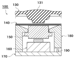
- An example of a two-stage switch is shown in FIG.
- the two-stage switch 100 of this example includes a keypad 130 on which a push button part 131 to be pressed is formed, a first switch part 140 disposed below the push button part 131, and a first switch part. Below 140, it has actuator 150 supported so that movement in the up-and-down direction was possible, and the 2nd switch part 160 arranged under actuator 150.
- the first switch unit 140, the actuator 150, and the second switch unit 160 are supported by a case 180 disposed on the upper surface of the substrate 170.
- the case 180, the actuator 150, the first switch unit 140, and the keypad 130 may be made of a transparent or translucent material.
- the first switch unit 140 is a flexible substrate in this example, and has a two-layer structure in which a part directly below the push button unit 131 sandwiches a space. When the upper layer and the lower layer are brought into contact with each other, the switch is turned on, and the lighting device 190 provided in the case 180 emits light.
- the second switch unit 160 is a general switch, and various operations are performed by pressing the switch.
- this two-stage switch 100 will be described.
- the two-layer structure portion of the flexible substrate 140 is pushed downward, and the two-layer structure portion is sandwiched between the lower surface of the push button portion 131 and the upper surface of the actuator 150 below the push button portion 131.
- the upper and lower layers come into contact with each other, and the switch is turned on.
- the illuminating device 190 emits light.
- Light is irradiated to the outside through the case 180, the actuator 150, and the keypad 130.
- the second-stage pressing operation of the push button unit 131 the second switch 160 is pressed via the flexible substrate 140 and the actuator, and various operations are performed.
- a switch using a click dome plate has been proposed as a switch for performing a one-step pressing operation (see, for example, Patent Document 1).
- the outer peripheral edge of the dome plate is in contact with the upper surface of the substrate.
- the top portion of the dome plate is recessed by elastic deformation, and the portion near the top contacts the contact disposed on the substrate.
- a click feeling is generated by the elastic deformation of the dome plate.
- ⁇ Capacitive or pressure sensitive sensors are used for switches using one liquid crystal touch panel. Various information is displayed on the panel. When a portion where desired information is displayed is pressed, the information is displayed on the panel. When a predetermined portion is further pressed, an operation related to the information is executed.
- the two-stage switch shown in FIG. 7 has a relatively large number of parts and requires a certain thickness due to its structure. Moreover, an expensive flexible substrate is used to reduce the thickness. Furthermore, when the lighting device is equipped, the lighting device cannot be disposed in a portion immediately below the push button portion, so that it must be disposed in a surrounding casing, and sufficient lighting performance cannot be obtained.
- liquid crystal touch panel when used, it can also serve as a display that displays information indicating which switch is pressed when the switch is turned on. However, it is not possible to obtain a clear operational feeling when the switch is turned on.
- electrostatic capacity type there are cases where the device does not operate normally due to a change in electrostatic voltage or a change in temperature such as when a hand is wet or when wearing gloves.
- the present invention has been made in view of the above points, and an object thereof is to provide a two-stage switch that has a small number of parts, can be thinned, and can obtain a clear click feeling.
- the two-stage switch of the present invention is a switch comprising a click dome plate having a movable contact, a keypad joined to the dome upper surface of the dome plate, and a fixed contact facing the movable contact,
- the fixed contact has a first-stage fixed contact and a second-stage fixed contact.
- the dome plate When the keypad is not pressed, the dome plate is held by the pad, and any of the fixed contacts It is in a floating state that is not in contact, and the movable contact of the dome plate comes into contact with the first stage fixed contact by the deformation of the pad by the first stage pressing operation of the keypad, and the second stage of the keypad The movable contact of the dome plate comes into contact with the second stage fixed contact by deformation accompanied by a click feeling of the dome plate by the pressing operation.
- the minimum required components are three components: a keypad, a dome plate, and a substrate on which a fixed contact is formed, and the number of components is reduced compared to a conventional general two-stage switch. I get out. Furthermore, since an expensive flexible substrate or the like is not used, it can be manufactured at low cost. Moreover, since the thickness of each component is relatively thin, it is possible to reduce the thickness.
- the keypad is deformed by the first-stage pressing operation, and the first-stage fixed contact is conducted.
- this pressing operation the degree of increase in reaction force with respect to the stroke is small.
- the keypad is first compressed in the vertical direction by the second-stage pressing operation.
- This operation can be performed with a large increase in reaction force.
- the reaction force reaches a peak, the dome plate is recessed and the second stage fixed contact is conducted.
- This operation may have a short stroke, a reaction force that decreases rapidly, and a click feeling. In this way, since the pressing characteristics of the first-stage pressing operation and the second-stage pressing operation can be different, it can be clearly felt that each switch operation has been performed.
- a preliminary operation such as displaying the fact that the switch has been pressed by a first-stage pressing operation in a visible manner (lighting a predetermined part, displaying it on the display, etc.) or notifying by voice. Can also be done. And this operation which performs the content relevant to the pressed switch by the press operation of the 2nd step can also be performed.
- the dustproof function and watertight function can be added to the keypad, the reliability of the switch can be improved. Furthermore, the operability does not change even when wet fingers or gloves are worn. Furthermore, since the temperature change is not related, it is more reliable.
- a preliminary operation for causing the operator to visually or audibly recognize that the operation has been performed is performed by pressing the first step of the keypad, and by pressing the second step of the keypad. This operation can be performed.
- the main operation is an operation that is originally executed by pressing a switch
- the preliminary operation is an operation that is performed in advance to execute the main operation.
- the preliminary operation is an operation for displaying information indicating which switch is pressed on the display on the front panel, and this operation executes the displayed contents. This is the original operation.
- a through-hole is formed in the dome plate, or the dome plate is made of a transparent or translucent material, and the keypad is made of a transparent or translucent material, A light source may be disposed below the dome plate.
- the light source when the light source emits light by the first-stage pressing operation, when a through hole is formed in the dome plate, light passes through the through hole of the dome plate, and the dome plate is made of a transparent or translucent material. In this case, the light passes through the dome plate and is irradiated through the keypad. Further, if the position of the pressing part is different from the position of the light emitting part, it is possible to emit light at a place different from the place pressed by the finger. Alternatively, if a light-shielding film is formed on the upper surface of a keypad made of a transparent or translucent material, and the character or pattern portion through which light is to be transmitted is removed with a laser, the character or pattern appears to shine. In this way, various illuminations are possible.
- a plurality of the dome plates are joined to a single keypad, and a plurality of switch portions can be formed.
- a plurality of switch portions can be provided on a single keypad, a simple appearance can be realized. Further, since the keypad can be shared, the cost is reduced. Furthermore, since there is no gap or slit between the switches, waterproofness and dustproofness can be obtained.
- the minimum necessary components of the two-stage switch of the present invention are three components, that is, a keypad, a dome plate, and a substrate on which a fixed contact is formed. Compared to stage switches, the number of parts is small. Furthermore, since an expensive flexible substrate or the like is not used, it can be manufactured at low cost. Moreover, since the thickness of each component is relatively thin, it is possible to reduce the thickness.
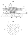
- FIG. 1 (A) is a sectional side view of a 2 step
- FIG.1 (B) is a top view of a fixed contact. It is a top view which shows the touchscreen provided with the two-stage type switch of FIG. It is a figure which shows the switch operation
- the touch panel 1 of this example displays information indicating which switch has been pressed by the first-stage pressing operation on a display or the like installed at a different location from the panel, and the second-stage pressing operation.
- the type of executing the displayed content As a specific example, information provided on the front panel of the steering wheel control panel is displayed on the front panel display by the first-stage pressing operation, and displayed by the second-stage pressing operation. The contents are executed.
- the touch panel 1 selects one mode from four modes A, B, C, and D.
- Each of the printed portions “A”, “B”, “C”, “D” of the panel forms a two-stage switch 10. For example, when a portion printed with “A” is pressed as the first-stage pressing operation, “A mode” is displayed on the front panel display. When the second-stage pressing operation is performed, a click feeling is obtained and the content of the “A mode” is executed.
- the two-stage switch 10 includes a click dome plate 20, a keypad 30, and a fixed contact 41 formed on the substrate 40.
- the dome plate 20 has a thin dome shape with a circular planar shape.
- the dome plate 20 is made of a material that is elastically deformed and depressed when the upper surface (for example, the vicinity of the apex) of the dome is pressed, and is restored to its original shape when released. A click feeling is given to the user during this elastic deformation. Examples of such a material include a metal (for example, stainless steel and copper alloy (phosphor bronze)), or a plate made of plastic (for example, PET and PC) (for example, in the case of metal, a thickness of 40 ⁇ m to 75 ⁇ m, In the case of plastic, the thickness is 75 ⁇ m to 125 ⁇ m).
- the dome plate 20 is produced by forming such a plate into a dome shape.
- the entire surface of the lower surface (the surface facing the fixed contact) of the dome plate 20 is a movable contact. Further, when made of plastic, conductive ink is applied to the entire surface of the lower surface or two portions of the lower surface that contact two types of fixed contacts 41 (details will be described later) formed on the upper surface of the substrate 40 during elastic deformation.
- the movable contact is formed by printing.
- the keypad 30 is a sheet-like member and is made of an elastic material (for example, silicon rubber or elastomer). In the case of the touch panel shown in FIG. 2, one keypad 30 is commonly used for all the two-stage switches 10. As described above, the keypad 30 is fitted into a window opened in a case or a board (steering wheel), and the outer peripheral portion is fixed to the back surface of the portion around the window.
- an elastic material for example, silicon rubber or elastomer
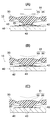
- a push button portion 31 is formed in a predetermined portion of the keypad 30.
- the push button part 31 has a thick central part 33 and a thin part (may be a skirt shape that gives a click feeling) 35 around it.
- the upper surface of the central portion 33 has a gentle convex shape, and characters “A” (or “B”, “C”, “D”) are printed on the same surface (see FIG. 2).
- a projecting portion 34 that protrudes downward is formed at the center of the lower surface of the central portion 33.
- a portion in the vicinity of the apex of the upper surface of the dome plate 20 is joined to the protrusion 34 by an adhesive or the like.
- the substrate 40 is a PCB substrate on which printed circuits are printed on both sides, for example, and is disposed below the keypad 30. At this time, there is a gap between the dome plate 20 joined to the push button portion 31 of the keypad 30 and the upper surface of the substrate 40, and no part of the dome plate 20 is in contact with the substrate 40. .
- a fixed contact 41 is formed on the upper surface of the substrate 40.
- the fixed contact 41 has a first-stage fixed contact 42 on the outer periphery and a second-stage fixed contact 43 at the center.
- the first stage fixed contact 42 is disposed so as to face the outer peripheral portion of the dome plate 20.
- the fixed contact 42 has two halves 42a and 42b in which the ring is halved. Each half is connected to a circuit on the upper surface of the substrate 40.
- the second stage fixed contact 43 is arranged in a ring shape so as to face the outer peripheral portion of the lower protrusion 34 of the push button portion 33 of the keypad 30.
- the fixed contact 43 passes through the substrate 40 and is connected to the circuit 44 on the back surface.
- Thickness H1 3.3 mm of the central portion 33 of the push button portion 31; Height H2 of the upper surface convex portion of the push button portion 31: 0.5 mm, The thickness H3 of the thin portion 35 of the push button portion 31 is 0.8 mm, The height H4 of the lower protrusion 34 of the push button 31 is 0.8 mm, The height H5 of the dome plate 20: 0.35 mm, A distance H6 between the lowermost portion of the dome plate 20 and the upper surface of the substrate 40: 0.4 mm.
- the height of this switch (the height from the upper surface of the substrate 40 to the uppermost surface of the push button portion 31) is 4.05 mm.
- substrate 40 is adjustable.
- paragraph fixed contact 42 is conduct
- “A mode” is displayed on the display mounted on the front panel.
- the degree of increase in the reaction force with respect to the stroke is low.
- the length of this stroke can be changed by adjusting the distance H6 between the lowermost portion of the dome plate 20 and the upper surface of the substrate 40 in FIG.
- the second stage fixed contact 42 and the first stage fixed contact 43 are conducted through the dome plate 20, and the second operation is performed.
- the content of “A mode” is executed.
- the advantages of this switch are shown below.
- the number of parts is basically three, that is, the keypad 30, the dome plate 20, and the substrate 40. Since an expensive flexible substrate or the like is not used, it can be manufactured at low cost. Furthermore, it is possible to reduce the thickness.
- a clear click feeling can be obtained by deformation of the dome plate 20.
- Characters and figures can be printed on the surface of the keypad 30 and there is no need to use an exterior panel or the like, so the number of parts can be reduced and the thickness can be reduced.
- a plurality of switches can be configured with a single keypad 30. In this case, since there is no gap or step between the switches, it has a dustproof and dripproof function.
- the first-stage pressing operation can be performed with a relatively light touch.
- the switch 10A in this example emits the switch or the information or display written on the switch so that it can be understood which switch is pressed by the first-stage pressing operation, and the information is displayed by the second-stage pressing operation. This is applied to a touch panel that performs an operation according to the display.
- the switch 10A in this example is composed of the keypad 30, the dome plate 20, and the substrate 40, similarly to the switch 10 in FIG. Only differences from the components in FIG. 1 will be described.
- the dome plate 20 has the same structure as the dome plate of the switch of FIG. 1, but has an opening 21 at the center. If the dome plate 20 can be made of a transparent or translucent material, the opening 21 does not necessarily have to be opened.
- the keypad 30 is the same as the keypad of the switch of FIG. 1, but a hole 37 having a certain depth is formed in the center of the lower protrusion 34 of the push button 31.
- the keypad 30 is made of a transparent or opaque material.
- the dome plate 20 is bonded to the lower surface of the ring-shaped portion around the hole portion 37. Further, a through hole 45 is formed at a position of the substrate 40 that faces the center of the lower protrusion 34 of the push button portion 31 of the keypad 30.
- An illumination device such as an LED lamp 50 is attached below the through hole 45. The LED lamp 50 is connected to the first-stage fixed contact 42 and illuminates when the fixed contact 42 becomes conductive.
- the lower protrusion 34 presses the dome plate 20 against the substrate 40, and the dome plate 20 is deformed into a substantially flat posture.
- the second stage fixed contact 42 and the first stage fixed contact 43 are conducted through the dome plate, and the second operation is performed.
- a switch 10 ⁇ / b> A shown in FIG. 5B has a light-shielding film 55 on the upper surface of the keypad 30. Is painted.
- the letters 55 for example, “A” and “B” on the panel in FIG. 2) and the pattern to be shined are marked on the coating 55 on the upper surface of the push button portion 33 by a marking laser or the like.
- a portion where characters are omitted is indicated by reference numeral 56. In this case, the light emitted from the LED lamp 50 is irradiated upward from the portion 56 where the characters are removed, and the characters and patterns appear to shine.
- the switch 10A of this example has the following advantages in addition to the advantages of the switch of FIG. In the conventional switch described with reference to FIG. 7, it is necessary to dispose the lighting device 190 to the side of the push button portion 131, so that it may be difficult to see the light from the outside.
- the switch 10 ⁇ / b> A in this example is guided through the push button portion 31 because the illumination device 50 is disposed directly below the central portion 33 of the push button portion 31. Actually, since the central portion 33 of the push button portion 31 is pressed by a finger and the finger blocks the illumination, the positions of the illumination device 50 and the central portion 33 of the push button portion 31 may be shifted.
- the switch 10B in FIG. 6A is a type in which one keypad 30 is provided with one push button portion.
- the keypad 30 of this switch has a push button part 31 whose upper surface is pressed and a base part 38 joined to the substrate 40.
- the push button portion 31 is formed in a dome shape having substantially the same thickness, and a downwardly protruding protrusion 34 is formed at the center of the lower surface.
- the dome plate 20 is bonded to the protrusion 34.
- the base portion 38 is bonded to the upper surface of the substrate 40.
- the switch 10 ⁇ / b> C in FIG. 6B is of a type incorporated in the outer case 60.
- the keypad 30 of this switch has a push button part 31 whose upper surface is pressed and a base part 38 joined to the substrate 40.
- the push button portion 31 includes a central portion 33 and a thin portion (skirt portion) 35 that supports the central portion 33 on the base portion 38.
- the central portion 33 has a flat rectangular parallelepiped shape, and a projecting portion 34 projecting downward is formed at the center of the lower surface.
- the dome plate 20 is bonded to the protrusion 34.
- the exterior case 60 has an opening 61 through which the push button portion 31 is exposed.
- FIG. 6C has a structure similar to that of the switch 10B in FIG. 6A, but the side end face of the keypad 30 and the side end face of the substrate 40 are made fluid-tight by a seal 70.
- FIG. This provides a waterproof function.
Abstract
Description
この例の2段式スイッチ100は、押圧操作される押しボタン部131が形成されたキーパッド130と、押しボタン部131の下方に配置された第1のスイッチ部140と、第1のスイッチ部140の下方に、上下方向に移動可能に支持されたアクチュエータ150と、アクチュエータ150の下方に配置された第2のスイッチ部160と、を有する。第1のスイッチ部140、アクチュエータ150及び第2のスイッチ部160は、基板170の上面に配置されたケース180に支持されている。ケース180、アクチュエータ150、第1のスイッチ部140及びキーパッド130は、透明あるいは半透明の材料で作製される場合もある。
具体的には、1段目の押圧動作により、スイッチが押されたことを視認可能な方法で表示(所定の部分を発光させる、ディスプレイに表示させるなど)したり、音声で知らせるなどの予備操作を行うこともできる。そして、2段目の押圧動作で、押されたスイッチに関連する内容を実行する本操作を行うこともできる。
まず、図2を参照して、本発明の第1の実施の形態に係る2段式スイッチを備えたタッチパネルについて説明する。
この例のタッチパネル1は、1段目の押圧動作によって、どのスイッチが押されたかを表示する情報を、同パネルと別の場所に設置されているディスプレイ等に表示し、2段目の押圧動作によって、表示された内容を実行するタイプのものである。具体例としては、ステアリングホイールの制御盤に設けられて、1段目の押圧動作によって、どのスイッチが押されたかを示す情報がフロントパネルのディスプレイに表示され、2段目の押圧動作によって、表示された内容が実行される。
2段式スイッチ10は、クリックドーム板20と、キーパッド30と、基板40上に形成された固定接点41と、を有する。
1段目固定接点42は、ドーム板20の外周部に対向するように配設されている。同固定接点42は、リングを半割にした2個の半割部42a、42bを有する。各半割部は、基板40の上面において各々回路に接続されている。
2段目固定接点43は、キーパッド30の押しボタン部33の下突部34の外周部に対向するようにリング状に配設されている。この固定接点43は、基板40を貫通して裏面の回路44に接続されている。
押しボタン部31の中央部33の厚さH1:3.3mm、
押しボタン部31の上面凸部の高さH2:0.5mm、
押しボタン部31の薄肉部35の厚さH3:0.8mm、
押しボタン部31の下突部34の高さH4:0.8mm、
ドーム板20の高さH5:0.35mm、
ドーム板20の最下部と基板40の上面間の間隔H6:0.4mm。
この場合、このスイッチの高さ(基板40の上面から押しボタン部31の最上面までの高さ)は、4.05mmとなる。なお、ドーム板20の最下部と基板40の上面間の間隔H6は調整可能である。
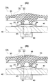
図1(A)に示す待機状態において、1段目の押圧動作によりキーパッド30の押しボタン部31の中央部33が押されると、図3(A)に示すように、その周囲の薄肉部35が変形して中央部33が下降し、まず、ドーム板20の外周部が、基板40の1段目固定接点42に接触する。これにより、1段目固定接点42の各半割部42a、42bがドーム板20を介して導通し、1回目の作業が行われる。例えば、フロントパネルに搭載されたディスプレイに、“Aモード”と表示される。この際、図5のグラフのaの部分に示すように、ストロークに対して反力の上昇度合いは低い。このストロークの長さは、図1(A)において、ドーム板20の最下部と基板40の上面との間隔H6を調整することにより変更できる。
そして、この反力がピークP1に達すると、図3(C)に示すように、ドーム板20が弾性変形してほぼ平坦な姿勢に凹む。この際、図4のグラフのcの部分に示すように、ストロークは短く反力が急激に減少する。この反力の急激な低下により、クリック感が生じる。同時に、図3(C)に示すように、ドーム板20の中央部が、基板40の2段目固定接点43に接触する。これにより2段目固定接点42と1段目固定接点43とがドーム板20を介して導通し、2回目の作業が行われる。例えば、“Aモード”の内容が実行される。
押しボタン部31の中央部33の押圧を解除すると、押しボタン部31とドーム板20はもとの姿勢に戻る。
(1)部品点数が、基本的にはキーパッド30、ドーム板20及び基板40の3点であり、高価なフレキシブル基板などを使用しないので、安価に製造できる。さらに、薄型化も可能である。
(2)ドーム板20の変形により明確なクリック感を得られる。
(3)キーパッド30の表面に文字や図形を印字でき、別に外装パネルなどを使用する必要がないため、部品点数の低減や薄型化が可能となる。
(4)一枚のキーパッド30で複数のスイッチを構成できる。この場合、スイッチ間にスキマや段差などが生じないので、防塵、防滴機能を有する。
(5)キーパッド30の表面に凹凸部を設けた場合は、ブラインドタッチが可能となる。特にステアリングホイールの制御盤に搭載する際は運転者が手元を見づらいので、ブラインドタッチしてその内容を運転者が見やすい位置に設けられたフロントパネルに表示させることにより、運転者が確認しやすくなる。
(6)比較的軽いタッチで1段目の押圧操作を行うこともできる。
この例のスイッチ10Aは、1段目の押圧動作によって、どのスイッチが押されたかがわかるように該スイッチ又は該スイッチに記された情報や表示を発光させ、2段目の押圧動作によって、その情報や表示に従った動作を実行するタイプのタッチパネルに適用される。
キーパッド30も図1のスイッチのキーパッドと同様であるが、押しボタン部31の下突部34の中央に、ある程度の深さの穴部37が形成されている。また、キーパッド30は透明あるいは不透明な材料で作製される。ドーム板20は、穴部37の周りのリング状の部分の下面に接着されている。
さらに、基板40の、キーパッド30の押しボタン部31の下突部34の中央に対向する位置には、貫通孔45が開けられている。そして、貫通孔45の下方にはLEDランプ50などの照明装置が取り付けられている。このLEDランプ50は、1段目の固定接点42に接続しており、同固定接点42が導通したときに照明する。
1段目の押圧動作によりキーパッド30の押しボタン部31の中央部33が押されると、前述の例と同様に、中央部33が下降し、ドーム板20の外周部が、基板40の1段目固定接点42に接触する。これにより、1段目固定接点42の各半割部がドーム板20を介して導通し、LEDランプ50が発光する。発せられた光は、基板40の貫通孔45、ドーム板20の開口21を通ってキーパッド30の押しボタン部31に形成された穴部37に入り、押しボタン部31を発光させる。次に、2段目の押圧動作によりさらに中央部33が押されると、下突部34がドーム板20を基板40に対して押し付け、ドーム板20がほぼ平坦な姿勢に変形する。これにより2段目固定接点42と1段目固定接点43とがドーム板を介して導通し、2回目の動作が行われる。
が塗装されている。そして、押しボタン部33の上面の被膜55に、光らせたい文字(例えば図2のパネルの“A”や“B”)や柄の形状にマーキングレーザー等で文字抜きされている。文字抜きされた部分を符号56で示す。この場合、LEDランプ50から発せられた光が文字抜きされた部分56から上方に照射されて、文字や柄が光って見える。
図7で説明した従来例のスイッチにおいては、照明装置190を押しボタン部131の側方に配置する必要があったので、外側から光を見づらい場合があった。一方、この例のスイッチ10Aは、押しボタン部31の中央部33の真下に照明装置50が配置されるので、押しボタン部31を通して導光される。なお、実際には、押しボタン部31の中央部33は指で押されており指が照明を遮るので、照明装置50と押しボタン部31の中央部33の位置をずらしてもよい。
図6(A)のスイッチ10Bは、一枚のキーパッド30に一個の押しボタン部を設けたタイプのものである。このスイッチのキーパッド30は、上面が押される押しボタン部31と、基板40に接合されるベース部38とを有する。押しボタン部31はほぼ同じ厚さのドーム状に形成されており、下面の中央に、下に凸の突部34が形成されている。この突部34にドーム板20が接着されている。ベース部38は基板40の上面に接合されている。
外装ケース60には、押しボタン部31が露出する開口61が開けられている。
20 クリックドーム板(ドーム板) 21 開口
30 キーパッド 31 押しボタン部
33 中央部 35 薄肉部
34 下突部 38 ベース部
40 基板 41 固定接点
42 1段目固定接点 43 2段目固定接点
44 回路 45 貫通孔
50 LEDランプ 60 外装ケース
61 開口 70 シール
Claims (4)
- 可動接点を有するクリックドーム板と、
該ドーム板のドーム上面に接合されたキーパッドと、
前記可動接点と対向する固定接点と、
を備えるスイッチであって、
前記固定接点が、1段目固定接点及び2段目固定接点を有し、
前記キーパッドを押圧操作していない状態においては、前記ドーム板は前記パッドに保持されて、いずれの前記固定接点にも接触していない浮揚状態にあり、
前記キーパッドの1段目の押圧操作による該パッドの変形によって、前記ドーム板の可動接点が前記1段目固定接点と接触し、
前記キーパッドの2段目の押圧操作による、前記ドーム板のクリック感を伴う変形によって、前記ドーム板の可動接点が前記2段目固定接点と接触する、
ことを特徴とする2段式スイッチ。 - 前記キーパッドの1段目の押圧操作により、該操作が行われたことを操作者に視覚あるいは聴覚で認識させる予備動作を行い、
前記キーパッドの2段目の押圧操作により本動作を行うことを特徴とする2段式スイッチ。 - 前記ドーム板に貫通孔が形成されているか、前記ドーム板が透明あるいは半透明な材料で作製されており、
前記キーパッドが透明あるいは半透明な材料で作製されており、
前記ドーム板の下方に光源が配置されていることを特徴とする請求項1又は2に記載の2段式スイッチ。 - 一枚の前記キーパッドに、複数枚の前記ドーム板が接合されており、複数のスイッチ部が形成されていることを特徴とする請求項1、2又は3に記載の2段式スイッチ。
Priority Applications (3)
| Application Number | Priority Date | Filing Date | Title |
|---|---|---|---|
| EP12782556.0A EP2709134A4 (en) | 2011-05-10 | 2012-04-06 | TWO-STAGE SWITCH |
| US14/115,508 US20140090967A1 (en) | 2011-05-10 | 2012-04-06 | Two-step switch |
| JP2012538110A JP5221819B2 (ja) | 2011-05-10 | 2012-04-06 | 2段式スイッチ |
Applications Claiming Priority (2)
| Application Number | Priority Date | Filing Date | Title |
|---|---|---|---|
| JP2011104866 | 2011-05-10 | ||
| JP2011-104866 | 2011-05-10 |
Publications (1)
| Publication Number | Publication Date |
|---|---|
| WO2012153587A1 true WO2012153587A1 (ja) | 2012-11-15 |
Family
ID=47139073
Family Applications (1)
| Application Number | Title | Priority Date | Filing Date |
|---|---|---|---|
| PCT/JP2012/059473 WO2012153587A1 (ja) | 2011-05-10 | 2012-04-06 | 2段式スイッチ |
Country Status (4)
| Country | Link |
|---|---|
| US (1) | US20140090967A1 (ja) |
| EP (1) | EP2709134A4 (ja) |
| JP (1) | JP5221819B2 (ja) |
| WO (1) | WO2012153587A1 (ja) |
Cited By (8)
| Publication number | Priority date | Publication date | Assignee | Title |
|---|---|---|---|---|
| JP2017098175A (ja) * | 2015-11-27 | 2017-06-01 | 信越ポリマー株式会社 | 押釦用スイッチ部材およびその製造方法 |
| JP2017157441A (ja) * | 2016-03-02 | 2017-09-07 | 信越ポリマー株式会社 | 押釦スイッチ |
| JP2017157434A (ja) * | 2016-03-02 | 2017-09-07 | 信越ポリマー株式会社 | 照光式押釦スイッチ部材 |
| JP2017157440A (ja) * | 2016-03-02 | 2017-09-07 | 信越ポリマー株式会社 | 押釦スイッチ |
| KR20180030969A (ko) | 2015-07-24 | 2018-03-27 | 신에츠 폴리머 가부시키가이샤 | 푸시버튼 스위치용 부재 |
| WO2018116702A1 (ja) * | 2016-12-22 | 2018-06-28 | 信越ポリマー株式会社 | 押釦スイッチ用部材 |
| WO2018235426A1 (ja) * | 2017-06-19 | 2018-12-27 | アルプス電気株式会社 | クリックばね付きシート、クリックばね付きシートの製造方法、およびスイッチ装置 |
| US10403451B2 (en) | 2015-06-25 | 2019-09-03 | Shin-Etsu Polymer Co., Ltd. | Pushbutton switch member |
Families Citing this family (34)
| Publication number | Priority date | Publication date | Assignee | Title |
|---|---|---|---|---|
| US9710069B2 (en) | 2012-10-30 | 2017-07-18 | Apple Inc. | Flexible printed circuit having flex tails upon which keyboard keycaps are coupled |
| US9449772B2 (en) | 2012-10-30 | 2016-09-20 | Apple Inc. | Low-travel key mechanisms using butterfly hinges |
| US9502193B2 (en) | 2012-10-30 | 2016-11-22 | Apple Inc. | Low-travel key mechanisms using butterfly hinges |
| AU2014214872B2 (en) | 2013-02-06 | 2017-05-25 | Apple Inc. | Input/output device with a dynamically adjustable appearance and function |
| TWI559350B (zh) | 2013-05-27 | 2016-11-21 | 蘋果公司 | 低行程薄膜按鍵、用於製造低行程薄膜按鍵之方法及關開總成 |
| US9908310B2 (en) | 2013-07-10 | 2018-03-06 | Apple Inc. | Electronic device with a reduced friction surface |
| WO2015047606A1 (en) | 2013-09-30 | 2015-04-02 | Apple Inc. | Keycaps having reduced thickness |
| KR101787301B1 (ko) | 2013-09-30 | 2017-10-18 | 애플 인크. | 감소된 두께를 가지는 키 캡 |
| US9793066B1 (en) | 2014-01-31 | 2017-10-17 | Apple Inc. | Keyboard hinge mechanism |
| US9779889B2 (en) | 2014-03-24 | 2017-10-03 | Apple Inc. | Scissor mechanism features for a keyboard |
| US9704665B2 (en) | 2014-05-19 | 2017-07-11 | Apple Inc. | Backlit keyboard including reflective component |
| US9715978B2 (en) | 2014-05-27 | 2017-07-25 | Apple Inc. | Low travel switch assembly |
| EP3180678A1 (en) | 2014-08-15 | 2017-06-21 | Apple Inc. | Fabric keyboard |
| US10082880B1 (en) | 2014-08-28 | 2018-09-25 | Apple Inc. | System level features of a keyboard |
| US9632591B1 (en) * | 2014-09-26 | 2017-04-25 | Apple Inc. | Capacitive keyboard having variable make points |
| WO2016053898A1 (en) | 2014-09-30 | 2016-04-07 | Apple Inc. | Light-emitting assembly for keyboard |
| WO2016183488A1 (en) | 2015-05-13 | 2016-11-17 | Apple Inc. | Keyboard assemblies having reduced thicknesses and method of forming keyboard assemblies |
| US9997308B2 (en) | 2015-05-13 | 2018-06-12 | Apple Inc. | Low-travel key mechanism for an input device |
| US9997304B2 (en) | 2015-05-13 | 2018-06-12 | Apple Inc. | Uniform illumination of keys |
| WO2016183510A1 (en) | 2015-05-13 | 2016-11-17 | Knopf Eric A | Keyboard for electronic device |
| US9934915B2 (en) | 2015-06-10 | 2018-04-03 | Apple Inc. | Reduced layer keyboard stack-up |
| US9971084B2 (en) | 2015-09-28 | 2018-05-15 | Apple Inc. | Illumination structure for uniform illumination of keys |
| US10256055B2 (en) * | 2016-07-08 | 2019-04-09 | Citizen Electronics Co., Ltd. | Push switch and electronic device including push switch |
| US10353485B1 (en) | 2016-07-27 | 2019-07-16 | Apple Inc. | Multifunction input device with an embedded capacitive sensing layer |
| US10115544B2 (en) | 2016-08-08 | 2018-10-30 | Apple Inc. | Singulated keyboard assemblies and methods for assembling a keyboard |
| US10755877B1 (en) | 2016-08-29 | 2020-08-25 | Apple Inc. | Keyboard for an electronic device |
| US11500538B2 (en) | 2016-09-13 | 2022-11-15 | Apple Inc. | Keyless keyboard with force sensing and haptic feedback |
| CN117270637A (zh) | 2017-07-26 | 2023-12-22 | 苹果公司 | 具有键盘的计算机 |
| US11661139B2 (en) | 2018-04-11 | 2023-05-30 | Sram, Llc | Electromechanical control device and methods for electromechanical control of a bicycle |
| TWI666669B (zh) * | 2018-05-24 | 2019-07-21 | 達方電子股份有限公司 | 彈性接觸件及輸入裝置 |
| USD909894S1 (en) | 2019-04-12 | 2021-02-09 | Verily Life Sciences Llc | Sensor enclosure |
| US10905601B2 (en) | 2019-04-12 | 2021-02-02 | Verily Life Sciences Llc | Wearable sensor enclosure |
| US11836297B2 (en) | 2020-03-23 | 2023-12-05 | Apple Inc. | Keyboard with capacitive key position, key movement, or gesture input sensors |
| US11505271B2 (en) * | 2020-05-27 | 2022-11-22 | Shimano Inc. | Operating device |
Citations (4)
| Publication number | Priority date | Publication date | Assignee | Title |
|---|---|---|---|---|
| JPS6375915U (ja) * | 1986-03-06 | 1988-05-20 | ||
| JPH08335424A (ja) | 1995-06-06 | 1996-12-17 | Smk Corp | Mtスイッチ |
| JP2001297657A (ja) * | 2000-04-13 | 2001-10-26 | Matsushita Electric Ind Co Ltd | スイッチおよびそれを用いた電子機器 |
| JP2002260479A (ja) * | 2001-03-01 | 2002-09-13 | Alps Electric Co Ltd | 照光付スイッチ装置 |
Family Cites Families (12)
| Publication number | Priority date | Publication date | Assignee | Title |
|---|---|---|---|---|
| US4194105A (en) * | 1977-01-13 | 1980-03-18 | Itt Industries, Inc. | Switches |
| US5661279A (en) * | 1995-10-26 | 1997-08-26 | Sunarrow Co., Ltd. | Pushbutton switch |
| US5717176A (en) * | 1996-07-17 | 1998-02-10 | United Technologies Automotive, Inc. | Sequentially operated membrane switches |
| JP2002245895A (ja) * | 2001-02-14 | 2002-08-30 | Yazaki Corp | ドームスイッチ |
| JP4171713B2 (ja) * | 2004-03-23 | 2008-10-29 | ホシデン株式会社 | プッシュオンスイッチ |
| JP4513688B2 (ja) * | 2005-08-17 | 2010-07-28 | パナソニック株式会社 | プッシュオンスイッチ |
| KR101312136B1 (ko) * | 2006-06-22 | 2013-09-26 | 코박 컴퍼니 리미티드 | 시소키 대응 스위치 |
| JP5083057B2 (ja) * | 2008-06-13 | 2012-11-28 | パナソニック株式会社 | プッシュスイッチ |
| US20100140065A1 (en) * | 2008-12-08 | 2010-06-10 | Hanbit Precision Co., Ltd. (Republic Of Korea) | Multi-step pressurized switch |
| CN102428533A (zh) * | 2009-05-22 | 2012-04-25 | 株式会社藤仓 | 开关装置以及电子设备 |
| CN101908428A (zh) * | 2009-06-08 | 2010-12-08 | 深圳富泰宏精密工业有限公司 | 按键结构及应用该按键结构的便携式电子装置 |
| JP2014099398A (ja) * | 2012-10-18 | 2014-05-29 | Panasonic Corp | プッシュスイッチ |
-
2012
- 2012-04-06 JP JP2012538110A patent/JP5221819B2/ja not_active Expired - Fee Related
- 2012-04-06 US US14/115,508 patent/US20140090967A1/en not_active Abandoned
- 2012-04-06 EP EP12782556.0A patent/EP2709134A4/en not_active Withdrawn
- 2012-04-06 WO PCT/JP2012/059473 patent/WO2012153587A1/ja active Application Filing
Patent Citations (4)
| Publication number | Priority date | Publication date | Assignee | Title |
|---|---|---|---|---|
| JPS6375915U (ja) * | 1986-03-06 | 1988-05-20 | ||
| JPH08335424A (ja) | 1995-06-06 | 1996-12-17 | Smk Corp | Mtスイッチ |
| JP2001297657A (ja) * | 2000-04-13 | 2001-10-26 | Matsushita Electric Ind Co Ltd | スイッチおよびそれを用いた電子機器 |
| JP2002260479A (ja) * | 2001-03-01 | 2002-09-13 | Alps Electric Co Ltd | 照光付スイッチ装置 |
Non-Patent Citations (1)
| Title |
|---|
| See also references of EP2709134A4 |
Cited By (15)
| Publication number | Priority date | Publication date | Assignee | Title |
|---|---|---|---|---|
| US10403451B2 (en) | 2015-06-25 | 2019-09-03 | Shin-Etsu Polymer Co., Ltd. | Pushbutton switch member |
| US10373775B2 (en) | 2015-07-24 | 2019-08-06 | Shin-Etsu Polymer Co., Ltd. | Pushbutton switch member |
| KR20180030969A (ko) | 2015-07-24 | 2018-03-27 | 신에츠 폴리머 가부시키가이샤 | 푸시버튼 스위치용 부재 |
| JP2017098175A (ja) * | 2015-11-27 | 2017-06-01 | 信越ポリマー株式会社 | 押釦用スイッチ部材およびその製造方法 |
| JP2017157441A (ja) * | 2016-03-02 | 2017-09-07 | 信越ポリマー株式会社 | 押釦スイッチ |
| JP2017157434A (ja) * | 2016-03-02 | 2017-09-07 | 信越ポリマー株式会社 | 照光式押釦スイッチ部材 |
| JP2017157440A (ja) * | 2016-03-02 | 2017-09-07 | 信越ポリマー株式会社 | 押釦スイッチ |
| KR20190094148A (ko) | 2016-12-22 | 2019-08-12 | 신에츠 폴리머 가부시키가이샤 | 푸시버튼 스위치용 부재 |
| JPWO2018116702A1 (ja) * | 2016-12-22 | 2019-07-18 | 信越ポリマー株式会社 | 押釦スイッチ用部材 |
| WO2018116702A1 (ja) * | 2016-12-22 | 2018-06-28 | 信越ポリマー株式会社 | 押釦スイッチ用部材 |
| DE112017006494T5 (de) | 2016-12-22 | 2019-09-12 | Shin-Etsu Polymer Co., Ltd. | Drucktastenschalterelement |
| US10930448B2 (en) | 2016-12-22 | 2021-02-23 | Shin-Etsu Polymer Co., Ltd. | Push-button switch member |
| WO2018235426A1 (ja) * | 2017-06-19 | 2018-12-27 | アルプス電気株式会社 | クリックばね付きシート、クリックばね付きシートの製造方法、およびスイッチ装置 |
| CN110753983A (zh) * | 2017-06-19 | 2020-02-04 | 阿尔卑斯阿尔派株式会社 | 带点按弹簧的片材、带点按弹簧的片材的制造方法、开关装置 |
| CN110753983B (zh) * | 2017-06-19 | 2022-04-29 | 阿尔卑斯阿尔派株式会社 | 带点按弹簧的片材、带点按弹簧的片材的制造方法、开关装置 |
Also Published As
| Publication number | Publication date |
|---|---|
| JP5221819B2 (ja) | 2013-06-26 |
| US20140090967A1 (en) | 2014-04-03 |
| JPWO2012153587A1 (ja) | 2014-07-31 |
| EP2709134A4 (en) | 2015-03-11 |
| EP2709134A1 (en) | 2014-03-19 |
Similar Documents
| Publication | Publication Date | Title |
|---|---|---|
| JP5221819B2 (ja) | 2段式スイッチ | |
| US8604370B2 (en) | Luminous keyboard | |
| JP5301118B2 (ja) | キーアセンブリ及びこれを備えた携帯端末機 | |
| US20100232861A1 (en) | Protective sheet and input device | |
| TWI489499B (zh) | 發光鍵盤 | |
| US20060283698A1 (en) | Illuminating membrane switch and illuminating keypad using the same | |
| TWM498913U (zh) | 按鍵結構及鍵盤模組 | |
| KR20160088491A (ko) | 가변 디스플레이 장치 | |
| TWI445034B (zh) | 鍵盤 | |
| JP2012186061A (ja) | 照光式キーボード装置 | |
| TW201421513A (zh) | 發光鍵盤 | |
| TWM408732U (en) | Light keyboard | |
| JP2015049800A (ja) | キーボード装置 | |
| JP2009026729A (ja) | 導光機能付き可動接点体とそれを用いた入力装置 | |
| TWI768940B (zh) | 具顯示面板的鍵盤裝置 | |
| JP2009076293A (ja) | キー入力装置 | |
| JP2007157384A (ja) | シートスイッチ | |
| JP2008243655A (ja) | 可動接点体およびそれを用いて構成した照光式パネルスイッチ | |
| WO2007145423A1 (en) | Light emitting keypad | |
| CN108779780B (zh) | 电风扇 | |
| JP2007194092A (ja) | メンブレンシート及びスイッチ装置 | |
| JP2002075116A (ja) | 押釦スイッチ用カバー部材 | |
| JP7011518B2 (ja) | 操作パネル | |
| JP6099084B2 (ja) | ティーチペンダントのシートキー | |
| JP2010192275A (ja) | 導光シートスイッチ |
Legal Events
| Date | Code | Title | Description |
|---|---|---|---|
| ENP | Entry into the national phase |
Ref document number: 2012538110 Country of ref document: JP Kind code of ref document: A |
|
| 121 | Ep: the epo has been informed by wipo that ep was designated in this application |
Ref document number: 12782556 Country of ref document: EP Kind code of ref document: A1 |
|
| WWE | Wipo information: entry into national phase |
Ref document number: 14115508 Country of ref document: US |
|
| WWE | Wipo information: entry into national phase |
Ref document number: 2012782556 Country of ref document: EP |
|
| NENP | Non-entry into the national phase |
Ref country code: DE |