WO2012147780A1 - 摺動材料、軸受用合金及び軸受用複層金属材 - Google Patents
摺動材料、軸受用合金及び軸受用複層金属材 Download PDFInfo
- Publication number
- WO2012147780A1 WO2012147780A1 PCT/JP2012/061071 JP2012061071W WO2012147780A1 WO 2012147780 A1 WO2012147780 A1 WO 2012147780A1 JP 2012061071 W JP2012061071 W JP 2012061071W WO 2012147780 A1 WO2012147780 A1 WO 2012147780A1
- Authority
- WO
- WIPO (PCT)
- Prior art keywords
- bearing
- mass
- sliding
- alloy
- sliding material
- Prior art date
- Legal status (The legal status is an assumption and is not a legal conclusion. Google has not performed a legal analysis and makes no representation as to the accuracy of the status listed.)
- Ceased
Links
Images


Classifications
-
- C—CHEMISTRY; METALLURGY
- C22—METALLURGY; FERROUS OR NON-FERROUS ALLOYS; TREATMENT OF ALLOYS OR NON-FERROUS METALS
- C22C—ALLOYS
- C22C9/00—Alloys based on copper
- C22C9/06—Alloys based on copper with nickel or cobalt as the next major constituent
-
- B—PERFORMING OPERATIONS; TRANSPORTING
- B23—MACHINE TOOLS; METAL-WORKING NOT OTHERWISE PROVIDED FOR
- B23K—SOLDERING OR UNSOLDERING; WELDING; CLADDING OR PLATING BY SOLDERING OR WELDING; CUTTING BY APPLYING HEAT LOCALLY, e.g. FLAME CUTTING; WORKING BY LASER BEAM
- B23K26/00—Working by laser beam, e.g. welding, cutting or boring
- B23K26/20—Bonding
- B23K26/32—Bonding taking account of the properties of the material involved
-
- B—PERFORMING OPERATIONS; TRANSPORTING
- B23—MACHINE TOOLS; METAL-WORKING NOT OTHERWISE PROVIDED FOR
- B23K—SOLDERING OR UNSOLDERING; WELDING; CLADDING OR PLATING BY SOLDERING OR WELDING; CUTTING BY APPLYING HEAT LOCALLY, e.g. FLAME CUTTING; WORKING BY LASER BEAM
- B23K26/00—Working by laser beam, e.g. welding, cutting or boring
- B23K26/34—Laser welding for purposes other than joining
-
- B—PERFORMING OPERATIONS; TRANSPORTING
- B32—LAYERED PRODUCTS
- B32B—LAYERED PRODUCTS, i.e. PRODUCTS BUILT-UP OF STRATA OF FLAT OR NON-FLAT, e.g. CELLULAR OR HONEYCOMB, FORM
- B32B15/00—Layered products comprising a layer of metal
- B32B15/01—Layered products comprising a layer of metal all layers being exclusively metallic
- B32B15/013—Layered products comprising a layer of metal all layers being exclusively metallic one layer being formed of an iron alloy or steel, another layer being formed of a metal other than iron or aluminium
- B32B15/015—Layered products comprising a layer of metal all layers being exclusively metallic one layer being formed of an iron alloy or steel, another layer being formed of a metal other than iron or aluminium the said other metal being copper or nickel or an alloy thereof
-
- C—CHEMISTRY; METALLURGY
- C22—METALLURGY; FERROUS OR NON-FERROUS ALLOYS; TREATMENT OF ALLOYS OR NON-FERROUS METALS
- C22C—ALLOYS
- C22C9/00—Alloys based on copper
-
- C—CHEMISTRY; METALLURGY
- C22—METALLURGY; FERROUS OR NON-FERROUS ALLOYS; TREATMENT OF ALLOYS OR NON-FERROUS METALS
- C22C—ALLOYS
- C22C9/00—Alloys based on copper
- C22C9/10—Alloys based on copper with silicon as the next major constituent
-
- F—MECHANICAL ENGINEERING; LIGHTING; HEATING; WEAPONS; BLASTING
- F16—ENGINEERING ELEMENTS AND UNITS; GENERAL MEASURES FOR PRODUCING AND MAINTAINING EFFECTIVE FUNCTIONING OF MACHINES OR INSTALLATIONS; THERMAL INSULATION IN GENERAL
- F16C—SHAFTS; FLEXIBLE SHAFTS; ELEMENTS OR CRANKSHAFT MECHANISMS; ROTARY BODIES OTHER THAN GEARING ELEMENTS; BEARINGS
- F16C33/00—Parts of bearings; Special methods for making bearings or parts thereof
- F16C33/02—Parts of sliding-contact bearings
- F16C33/04—Brasses; Bushes; Linings
- F16C33/06—Sliding surface mainly made of metal
- F16C33/12—Structural composition; Use of special materials or surface treatments, e.g. for rust-proofing
- F16C33/122—Multilayer structures of sleeves, washers or liners
- F16C33/124—Details of overlays
-
- B—PERFORMING OPERATIONS; TRANSPORTING
- B23—MACHINE TOOLS; METAL-WORKING NOT OTHERWISE PROVIDED FOR
- B23K—SOLDERING OR UNSOLDERING; WELDING; CLADDING OR PLATING BY SOLDERING OR WELDING; CUTTING BY APPLYING HEAT LOCALLY, e.g. FLAME CUTTING; WORKING BY LASER BEAM
- B23K2103/00—Materials to be soldered, welded or cut
- B23K2103/18—Dissimilar materials
- B23K2103/22—Ferrous alloys and copper or alloys thereof
-
- F—MECHANICAL ENGINEERING; LIGHTING; HEATING; WEAPONS; BLASTING
- F16—ENGINEERING ELEMENTS AND UNITS; GENERAL MEASURES FOR PRODUCING AND MAINTAINING EFFECTIVE FUNCTIONING OF MACHINES OR INSTALLATIONS; THERMAL INSULATION IN GENERAL
- F16C—SHAFTS; FLEXIBLE SHAFTS; ELEMENTS OR CRANKSHAFT MECHANISMS; ROTARY BODIES OTHER THAN GEARING ELEMENTS; BEARINGS
- F16C2204/00—Metallic materials; Alloys
- F16C2204/10—Alloys based on copper
-
- F—MECHANICAL ENGINEERING; LIGHTING; HEATING; WEAPONS; BLASTING
- F16—ENGINEERING ELEMENTS AND UNITS; GENERAL MEASURES FOR PRODUCING AND MAINTAINING EFFECTIVE FUNCTIONING OF MACHINES OR INSTALLATIONS; THERMAL INSULATION IN GENERAL
- F16C—SHAFTS; FLEXIBLE SHAFTS; ELEMENTS OR CRANKSHAFT MECHANISMS; ROTARY BODIES OTHER THAN GEARING ELEMENTS; BEARINGS
- F16C2223/00—Surface treatments; Hardening; Coating
- F16C2223/30—Coating surfaces
- F16C2223/46—Coating surfaces by welding, e.g. by using a laser to build a layer
Definitions
- the present invention relates to a sliding material used for a bearing, a bearing alloy, and a multilayer metal material for the bearing.
- a bearing configured by bonding a bearing alloy to a base metal such as a steel plate. Since such a bearing uses a steel plate having high mechanical strength as a backing metal, it has a feature that it can withstand a high load compared to a ball bearing or a roller bearing.
- cylindrical bearings called bushes are used as bearings for parts that are subjected to high loads, such as downwheels in construction machines such as bulldozers and power shovels, and as power bearings for automobiles that are loaded and rotate at high speed. Many are used.
- flat plate bearings called flat bearings are often used as sliding parts that are subjected to high loads in compressors, hydraulic pumps, and the like.
- Bearing alloys used for bushes and plain bearings are required to have low friction characteristics, and conventionally, sliding materials containing Cu as a main component and containing Pb have been used (for example, see Patent Document 1).
- the present invention provides a sliding material having hardness suitable for bearings, excellent wear resistance, low friction characteristics and excellent slidability, a bearing alloy and a bearing using the sliding material. It aims at providing a multilayer metal material.
- the present inventors have found a combination of compositions having hardness suitable for bearings and excellent wear resistance in Cu—Ni—Si alloys used as electrical contact materials. Also, depending on the composition, it has been found that there are differences in the characteristics of bearings, such as in oil and dry environments. It has low friction and low wear characteristics and is excellent in slidability, making it ideal for use in bearings. Found a combination of various compositions.
- the present invention is a sliding material containing 0.5 to 10.0% by mass of Ni, 0.1 to 5.0% by mass of Si, 0.1 to 5.0% by mass of Cr, the balance being Cu and inevitable impurities, and containing Sn at the impurity level. is there.
- the sliding material of the present invention preferably contains Bi, and preferably contains 2.0 to 20.0% by mass of Bi in order to improve the slidability by imparting low friction characteristics.
- the present invention is a powder form containing Ni of 0.5 to 10.0% by mass, Si of 0.1 to 5.0% by mass, Cr of 0.1 to 5.0% by mass, the balance being made of Cu and inevitable impurities, and Sn at the impurity level.
- a powdery sliding material containing 2.0 to 20.0% by mass of Bi in addition to the above-described composition is a bearing alloy that is molded into a predetermined shape and sintered.
- the present invention includes a sliding element containing 0.5 to 10.0% by mass of Ni, 0.1 to 5.0% by mass of Si and 0.1 to 5.0% by mass of Cr, the balance being made of Cu and inevitable impurities, and Sn at the impurity level.
- the material or the sliding metal material containing 2.0 to 20.0 mass% Bi in addition to the above-described composition is a multi-layer metal material for a bearing in which the sliding surface is formed by joining one surface of the base metal.
- the addition of Ni in the Cu—Ni—Si alloy has the effect of reducing wear due to the improvement in hardness.
- the addition of Si is a Ni 2 Si precipitates by combining with Ni, addition of Cr is, Cu and melt into, as well as promotes the precipitation of Ni 2 Si by thermal treatment, by compounds with Si, Kuromukei By forming a compound, it has the effect of reducing wear.
- the sliding material of the present invention there is a difference in the coefficient of friction between the oil-in environment and the dry environment in terms of the composition ratio of Cu-Ni-Si-Cr. Then, compared to the case where the addition amounts of Si and Cr are comparable, by increasing the addition amount of Ni, the wear resistance is improved, and in either an oily environment or a dry environment. However, a friction reducing effect can be obtained.
- ⁇ Sn contained at the impurity level during refining of each alloy does not affect the effect of reducing friction and wear by adding Ni, Si, Cr.
- the sliding material of the present invention by containing Cu-Ni-Si-Cr and Sn at the impurity level, a sliding material having hardness suitable for a bearing and excellent wear resistance can be realized.
- the composition of Cu-Ni-Si-Cr realizes a sliding material with low friction and low wear characteristics and excellent slidability in bearing-specific usage environments such as in oil and dry environments. it can.
- the sliding material of the present embodiment is made of a Cu—Ni—Si based alloy, containing 0.5 to 10.0 mass% of Ni, 0.1 to 5.0 mass% of Si, 0.1 to 5.0 mass% of Cr, and the balance being Cu. It consists of unavoidable impurities and contains Sn at the impurity level. It is preferable that the ratio of Si and Cr for improving the slidability is about 2: 1 in either an oily environment or a dry environment.
- Bi in order to improve the slidability by imparting low friction characteristics, it is preferable to include Bi, and it is preferable to include 2.0 to 20.0% by mass of Bi.
- ⁇ Ni contained in Cu-Ni-Si alloy melts with Cu and has the effect of improving mechanical properties.
- the addition amount of Ni is less than 0.5% by mass, wear increases due to a decrease in mechanical properties and hardness.
- the addition amount of Ni exceeds 10.0% by mass, the alloy becomes hard but has no effect on wear reduction.
- Si contained in the Cu-Ni-Si alloy precipitates Ni 2 Si when combined with Ni.
- the addition amount of Si is less than 0.1% by mass, the precipitation of Ni 2 Si is extremely reduced, and the load resistance during sliding is lowered.
- the addition amount of Si exceeds 5.0% by mass, the material becomes brittle due to excessive extraction of Ni 2 Si, which falls off during sliding and promotes generation of wear powder, and causes abnormal wear such as abrasive wear.
- the addition of Cr in the Cu-Ni-Si alloy melts with Cu and accelerates the precipitation of Ni 2 Si by heat treatment, and forms a chromium silicide by combining with Si.
- the added amount of Cr is less than 0.1% by mass, precipitation strengthening of Ni 2 Si is not performed and wear increases.
- the amount of Cr exceeds 5.0% by mass, the amount of hard chrome silicide increases, which drops off during sliding and promotes the generation of wear powder, causing abnormal wear such as abrasive wear.
- the addition amounts of Si and Cr are comparable, the hardness is improved by the addition of Ni, but the friction reduction effect tends to decrease by increasing the addition amount of Ni. If the amount of Ni added is about 2 to 3 times, an effect of reducing friction under an oil-in-water environment can be obtained. On the other hand, when the amount of Si added to Cr is about twice, the structure is such that Ni, Si, Cr is precipitated in the matrix, and in addition to improving wear resistance by adding Ni, the friction reducing effect is improved. If the amount of Ni added is about 6 to 7 times that of Cr, a friction reducing effect can be obtained in both an oil-in-oil environment and a dry environment.
- Cu-Sn alloys have good corrosion resistance, and the addition of Sn in Cu-Ni-Si alloys has the effect of promoting cold plastic working performance after heat treatment.
- the addition amount of Sn is as small as about 0.1 to 0.3% by mass, it does not particularly contribute to the improvement of slidability as a sliding material. Therefore, Sn in this case is included at the impurity level during the refining of each alloy.
- the addition of Bi in the Cu-Ni-Si alloy plays the role of self-lubricating as a sliding material like Pb, and has the effect of improving the sliding characteristics without adding Pb.
- the added amount of Bi is less than 2.0% by mass, the self-lubricating function is not fully exhibited, leading to frictional heat generation and an increase in friction coefficient, leading to early seizure.
- the added amount of Bi exceeds 20.0% by mass, Bi elution on the sliding contact surface becomes prominent due to frictional heat generation, leading to an increase in adhesion and wear.
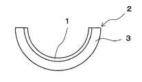
- FIG. 1A is a configuration diagram showing an example of a bearing alloy and a multilayer metal material for a bearing in which the sliding material of the present embodiment is used, and FIGS. 1B and 1C use the sliding material of the present embodiment. It is a manufacturing process figure which shows an example of the manufacturing method of the obtained alloy for bearings and the multilayer metal material for bearings.
- the bearing alloy 1 of the present embodiment is configured by compacting and sintering a powdery sliding material having the above-described composition into a predetermined shape.
- the bearing multi-layer metal material 2 of the present embodiment has a bearing alloy 1 bonded to one surface of a base metal 3 such as a steel material, and the sliding surface is a bearing alloy 1. Composed. Multi-layered metal materials made by joining steel and bearing alloy are designed to smoothly slide the sliding member with bearing alloy that supports high load with high mechanical strength steel and has sliding properties. ing.
- the bearing multilayer metal material 2 of the present embodiment is formed by compacting a powdered sliding material having the above-described composition into a predetermined shape and sintering it.
- the produced bearing alloy 1A is joined to a base metal 3A having a predetermined shape.
- the Cu—Ni—Si alloy has a high elongation rate of 5% or more, and the sliding material of the present embodiment can be produced as a thin wire. Therefore, as shown in FIG. 1C, the wire-shaped sliding material 4 having the above-described composition is supplied, and the laser beam S for welding is irradiated onto the wire-shaped sliding material 4 using the laser welding machine 5. As shown in FIG. 1A, overlay welding is performed on the base metal 3B, and the sliding material layer 1B made of the Cu—Ni—Si based alloy of the present embodiment is formed on one surface of the base metal 3B. A multi-layer metal material 2 for bearings is produced.
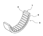
- FIG. 2 is a configuration diagram showing another example of a bearing alloy and a bearing multilayer metal material using the sliding material of the present embodiment.
- the bearing alloy 6 according to another embodiment is formed in a linear shape by rolling a sliding material having the above-described composition.
- the multi-layer metal material 7 for a bearing according to another embodiment is a cradle bearing having a configuration in which a plurality of cylindrical rollers are arranged between an inner race and an outer race, for example, used in a disk brake of a vehicle.
- An example in which a wire-like bearing alloy 6 having the above-described composition is used instead of the cylindrical roller is shown.
- the wire-like bearing alloy 6 is cut to a predetermined size and welded to the base metal 8 to form a semicircular bearing 9 in this example.
- the sliding material is the wire bearing alloy 6, the wire-like bearing alloy 6 is supplied to the base metal 8, cut to a predetermined length, overlay welding, etc. A series of processes can be performed using an automatic machine.
- Test pieces of Examples and Comparative Examples were prepared with the compositions shown in Table 1 below, and the dynamic friction coefficient, static friction coefficient, and specific wear amount in an oil-in-water environment and a dry environment were measured.
- a test piece is fixed inside a test container, and a mating material is rotated with a preset load and operation pattern in an oil-in-water environment and a dry environment, respectively.
- the dynamic friction coefficient, static friction coefficient, and specific wear amount were measured under the environment.
- Test machine used Thrust tester Test environment: Diesel engine oil (when in oil), no oil (when dry)
- Mating material SCM435 (chromium molybdenum steel)
- each of the Cu—Ni—Si based alloys having the compositions shown in Examples 1 to 3 showed high hardness characteristics, and as shown in Tables 1 and 2, either in an oily environment or in a dry environment. Even the amount of wear is small.
- the Cu—Ni—Si alloys having the compositions shown in Example 1 and Example 2 exhibit low friction and low wear characteristics in an oil environment.
- the Cu—Ni—Si alloy having the composition shown in Example 1 exhibits low friction and low wear characteristics even in a dry environment.
- the Cu—Ni—Si alloys having the compositions shown in Examples 1 to 3 showed low friction characteristics with a low friction coefficient without adding Pb, and added Pb. Compared with the sliding material, it has high hardness characteristics, so that the specific wear amount is kept low and exhibits low wear characteristics, and better sliding characteristics can be obtained than when Pb is added. Thereby, in the present invention, a sliding material for bearings having good sliding characteristics can be realized with Pb (lead) free, and since it has high hardness characteristics, even if it is applied to a part where a high load is applied, Good sliding characteristics can be obtained.
- the Cu—Ni—Si based alloy having the composition shown in Example 1 exhibits good low friction and low wear characteristics in both an oil-in-oil environment and a dry environment. This is suitable for such a boundary lubrication state.
- the Cu—Ni—Si based alloy having the composition shown in Example 2 exhibits good low friction and low wear characteristics in an oil environment, and is therefore suitable for a site where oil film breakage is relatively difficult, such as liquid lubrication. It is.
- the Cu-Ni-Si alloys having the compositions shown in Examples 1 to 3 all have a high hardness characteristic with a Vickers hardness (HV) of about 200.
- HV Vickers hardness
- the cavitation and erosion resistance is excellent in the field of hydraulic machines, and alloy erosion and fatigue hardly occur.
- the sliding material of the present invention exhibits good low friction and low wear characteristics even in a dry environment, it can also be applied to bearings used in areas where it is difficult to form an oil film.
Landscapes
- Engineering & Computer Science (AREA)
- Mechanical Engineering (AREA)
- Chemical & Material Sciences (AREA)
- Optics & Photonics (AREA)
- Physics & Mathematics (AREA)
- Materials Engineering (AREA)
- Metallurgy (AREA)
- Organic Chemistry (AREA)
- General Engineering & Computer Science (AREA)
- Plasma & Fusion (AREA)
- Sliding-Contact Bearings (AREA)
- Powder Metallurgy (AREA)
- Laser Beam Processing (AREA)
Abstract
軸受に適した硬度を持つことで耐磨耗性に優れ、更に、低摩擦の特性を持つことで摺動性に優れた摺動材料を提供する。 Cu-Ni-Si系合金で構成される摺動材料で、Niを0.5~10.0質量%、Siを0.1~5.0質量%、Crを0.1~5.0質量%含み、残部がCuと不可避的な不純物からなり、不純物レベルでSnを含む。低摩擦の特性を持たせて摺動性を向上させるためには、Biを含むことが好ましく、Biを2.0~20.0質量%含むことが好ましい。
Description
本発明は、軸受に使用される摺動材料、軸受用合金及び軸受用複層金属材に関する。
従来から、鋼板等の基材金属に軸受合金を張り合わせて構成される軸受が提案されている。このような軸受は、機械的強度の高い鋼板を裏金として使用しているため、ボールベアリングやローラーベアリングに比べて高荷重に耐えられるという特長を有している。
このため、ブッシュと称される円筒形状の軸受は、ブルドーザーやパワーシャベル等の建設機械における下転輪のように高荷重がかかる部分や、荷重がかかるとともに高速回転する自動車の動力部の軸受として多く使用されている。
また、平軸受と称される平板形状の軸受は、コンプレッサー、油圧ポンプ等において高荷重のかかる摺動部分として多く使用されている。
ブッシュや平軸受に用いられる軸受合金は、低摩擦の特性が求められ、従来は、Cuを主成分とし、Pbを含む摺動材料が用いられていた(例えば、特許文献1参照)。
従来は、摺動材料にPbを含むことで、低摩擦特性を実現していた。一方、摺動材料にPbを含むことで硬度が低下し、高荷重下での耐磨耗性に劣る。また、環境への負荷を低減させる取り組みとして、Pbを含まずとも、低摩擦と低摩耗の特性を持つ摺動材料が求められる。
本発明は、軸受に適した硬度を持ち耐磨耗性に優れ、更に、低摩擦の特性を持ち摺動性に優れた摺動材料、この摺動材料が用いられた軸受用合金及び軸受用複層金属材を提供することを目的とする。
本発明者らは、電気接点材料として用いられるCu-Ni-Si系合金において、軸受に適した硬度を持ち耐磨耗性に優れる組成の組み合わせを見出した。また、組成によって、油中環境下やドライ環境下といった軸受特有の使用環境で特性に差異が出ることを見出し、低摩擦と低摩耗の特性を持ち摺動性に優れ、軸受けに使用して最適な組成の組み合わせを見出した。
本発明は、Niを0.5~10.0質量%、Siを0.1~5.0質量%、Crを0.1~5.0質量%含み、残部がCuと不可避的な不純物からなり、不純物レベルでSnを含む摺動材料である。本発明の摺動材料は、低摩擦の特性を持たせて摺動性を向上させるためには、Biを含むことが好ましく、Biを2.0~20.0質量%含むことが好ましい。
また、本発明は、Niを0.5~10.0質量%、Siを0.1~5.0質量%、Crを0.1~5.0質量%含み、残部がCuと不可避的な不純物からなり、不純物レベルでSnを含む粉末状の摺動材料、または、上述した組成に加えてBiを2.0~20.0質量%含む粉末状の摺動材料が、所定の形状に成型されて焼結された軸受用合金である。
更に、本発明は、Niを0.5~10.0質量%、Siを0.1~5.0質量%、Crを0.1~5.0質量%含み、残部がCuと不可避的な不純物からなり、不純物レベルでSnを含む摺動材料、または、上述した組成に加えてBiを2.0~20.0質量%含む摺動材料が、基材金属の一の面に接合されて摺動面を構成した軸受用複層金属材である。
本願発明の摺動材料では、Cu-Ni-Si系合金におけるNiの添加は、硬度の向上による磨耗低減の効果を持つ。Siの添加は、Niと化合することによりNi2Siを析出し、Crの添加は、Cuと溶け合い、熱処理を施すことによりNi2Siの析出を促進すると共に、Siと化合することにより、クロムケイ化物を形成することで、磨耗低減の効果を持つ。
また、本願発明の摺動材料では、Cu-Ni-Si-Crの組成比で油中環境下及びドライ環境下での摩擦係数に違いがあり、Crに対してSiの添加量を2倍程度とすると、SiとCrの添加量が同等程度である場合と比較して、Niの添加量を増やすことにより、耐磨耗性を向上させると共に、油中環境下及びドライ環境下の何れであっても、摩擦低減効果が得られる。
各合金精錬時に不純物レベルで含まれるSnは、Ni,Si,Crの添加による摩擦低減及び磨耗低減の効果に影響を及ぼすことは無い。
従って、本発明の摺動材料では、Cu-Ni-Si-Crを含み、不純物レベルでSnを含むことで、軸受に適した硬度を持ち耐磨耗性に優れた摺動材料を実現できる。また、Cu-Ni-Si-Crの組成によって、油中環境下及びドライ環境下等の軸受特有の使用環境で、低摩擦及び低摩耗の特性を持ち摺動性に優れた摺動材料を実現できる。これにより、本発明の摺動材料で構成される軸受合金、及び、本発明の摺動材料で摺動面が構成される軸受用複層金属材で、摺動部の軸受を構成することで、機械装置の発熱低減や寿命向上を図ることができる。また、Biの添加で、摺動性を更に向上させる効果が期待できる。
特に、Cu-Ni-Si-Crの組成によって高硬度特性を持たせることで、油圧機械の分野において、耐キャビテーション・エロージョン性に優れるため、合金の浸食や疲労が起こり難い効果がある。また、Cu-Ni-Si-Crの組成によってドライ環境下で低摩擦及び低摩耗の特性を持たせることで、油膜の形成し難い部位でも安定した摺動性が得られる。
<本実施の形態の摺動材料の組成例>
本実施の形態の摺動材料は、Cu-Ni-Si系合金で構成され、Niを0.5~10.0質量%、Siを0.1~5.0質量%、Crを0.1~5.0質量%含み、残部がCuと不可避的な不純物からなり、不純物レベルでSnを含む。油中環境下及びドライ環境下の何れであっても摺動性を向上させるためのSiとCrの比率は、2:1程度であることが好ましい。
本実施の形態の摺動材料は、Cu-Ni-Si系合金で構成され、Niを0.5~10.0質量%、Siを0.1~5.0質量%、Crを0.1~5.0質量%含み、残部がCuと不可避的な不純物からなり、不純物レベルでSnを含む。油中環境下及びドライ環境下の何れであっても摺動性を向上させるためのSiとCrの比率は、2:1程度であることが好ましい。
また、低摩擦の特性を持たせて摺動性を向上させるためには、Biを含むことが好ましく、Biを2.0~20.0質量%含むことが好ましい。
Cu-Ni-Si系合金に含まれるNiは、Cuと溶け合って機械的性質を向上させる効果を持つ。但し、Niの添加量が0.5質量%未満であると、機械的性質、硬度低下により磨耗が増える。一方、Niの添加量が10.0質量%を超えると、合金は硬くなるが、磨耗低減に効果がない。
Cu-Ni-Si系合金に含まれるSiは、Niと化合することによりNi2Siを析出する。但し、Siの添加量が0.1質量%未満であると、Ni2Siの析出が極端に少なくなり、摺動時の耐荷重性が低下する。一方、Siの添加量が5.0質量%を超えると、Ni2Siの抽出過多により材料が脆くなり、これが摺動時に脱落して磨耗粉生成を促進させ、アブレシブ磨耗等の異常磨耗を引き起こす。
Cu-Ni-Si系合金におけるCrの添加は、Cuと溶け合い、熱処理を施すことによりNi2Siの析出を促進すると共に、Siと化合することにより、クロムケイ化物を形成する。但し、Crの添加量が0.1質量%未満であると、Ni2Siの析出強化がなされず、磨耗が増える。一方、Crの添加量が5.0質量%を超えると、硬質のクロムケイ化物が多くなりすぎ、これが摺動時に脱落して磨耗粉生成を促進させ、アブレシブ磨耗等の異常磨耗を引き起こす。
ここで、SiとCrの添加量が同等程度であると、Niの添加で硬度は向上するが、Niの添加量を増やすことで摩擦低減効果が低下する傾向にあり、SiとCrに対してNiの添加量を2~3倍程度とすれば、油中環境下での摩擦低減効果が得られる。一方、Crに対してSiの添加量を2倍程度とすると、マトリックス中にNi,Si,Crが析出した組織となり、 Niの添加による耐磨耗性の向上に加えて、摩擦低減効果が向上し、Crに対してNiの添加量を6~7倍程度とすれば、油中環境下及びドライ環境下の何れであっても摩擦低減効果が得られる。
Cu-Sn系合金は、耐食性が良好であり、Cu-Ni-Si系合金におけるSnの添加は、熱処理後の冷間塑性加工の性能を促進させる効果を持つ。但し、Snの添加量が0.1~0.3質量%程度の微量では、摺動材料としての摺動性向上には特に寄与しない。従って、この場合のSnは、各合金精錬時に不純物レベルで含まれるものである。
Cu-Ni-Si系合金におけるBiの添加は、Pbと同様に、摺動材料としての自己潤滑の役割を担い、Pbを添加しなくても、摺動特性を向上させる効果を持つ。但し、Biの添加量が2.0質量%未満であると、自己潤滑機能が十分に発揮されず、摩擦発熱、摩擦係数増加につながり、早期焼き付きに至る。一方、Biの添加量が20.0質量%を超えると、摩擦発熱により摺接面へのBi溶出が顕著になり、固着や磨耗量増加につながる。
<本実施の形態の軸受用合金及び軸受用複層金属材の構成例>
図1Aは、本実施の形態の摺動材料が用いられた軸受用合金及び軸受用複層金属材の一例を示す構成図、図1B及び図1Cは、本実施の形態の摺動材料が用いられた軸受用合金及び軸受用複層金属材の作製方法の一例を示す作製工程図である。本実施の形態の軸受用合金1は、上述した組成を有した粉末状の摺動材料が、所定の形状に圧粉成型され、焼結されて構成される。
図1Aは、本実施の形態の摺動材料が用いられた軸受用合金及び軸受用複層金属材の一例を示す構成図、図1B及び図1Cは、本実施の形態の摺動材料が用いられた軸受用合金及び軸受用複層金属材の作製方法の一例を示す作製工程図である。本実施の形態の軸受用合金1は、上述した組成を有した粉末状の摺動材料が、所定の形状に圧粉成型され、焼結されて構成される。
本実施の形態の軸受用複層金属材2は、図1Aに示すように、鋼材等の基材金属3の一の面に軸受用合金1が接合され、摺動面が軸受用合金1で構成される。鋼材と軸受用合金とを接合した複層金属材は、機械的強度に強い鋼材で高荷重を支え、摺動性を持たせた軸受用合金で摺動部材を円滑に摺動させるようになっている。
本実施の形態の軸受用複層金属材2は、例えば、図1Bに示すように、上述した組成を有した粉末状の摺動材料を所定の形状に圧粉成型し、焼結して作製された軸受用合金1Aを、所定の形状の基材金属3Aに接合して作製される。
また、Cu-Ni-Si系合金は、伸び率が5%以上と高く、本実施の形態の摺動材料は、細線材として作製できる。そこで、図1Cに示すように、上述した組成を有した線材状の摺動材料4を供給し、レーザ溶接機5を用いて溶接用レーザ光Sを線材状の摺動材料4に照射して、基材金属3Bに肉盛溶接を行い、基材金属3Bの一の面に本実施の形態のCu-Ni-Si系合金による摺動材料層1Bを形成することで、図1Aに示すような軸受用複層金属材2が作製される。
<他の実施の形態の軸受用合金及び軸受用複層金属材の構成例>
図2は、本実施の形態の摺動材料が用いられた軸受用合金及び軸受用複層金属材の他の例を示す構成図である。他の実施の形態の軸受用合金6は、上述した組成を有した摺動材料が圧延されて線状に構成される。
図2は、本実施の形態の摺動材料が用いられた軸受用合金及び軸受用複層金属材の他の例を示す構成図である。他の実施の形態の軸受用合金6は、上述した組成を有した摺動材料が圧延されて線状に構成される。
他の実施の形態の軸受用複層金属材7は、例えば車両のディスクブレーキ等に用いられる、インナーレースとアウターレース間に複数の円柱状ころが配される構成からなるクレードル軸受において、複数の円柱状ころの代わりに上述した組成を有した線材状の軸受用合金6を使用した一例を示すものである。線材状の軸受用合金6は所定寸法にカットされて基材金属8に溶接されて、本例では半円形状の軸受9が構成される。
摺動材料を線材の軸受用合金6としたので、基材金属8に対して、線材状の軸受用合金6を供給すること、所定の長さにカットすること、肉盛り溶接すること等、一連の工程が自動機を使った作業とすることが出来る。
以下の表1に示す組成で実施例と比較例の試験片を作製し、油中環境下及びドライ環境下での動摩擦係数、静止摩擦係数、比磨耗量を測定した。測定方法としては、試験片を試験容器の内部に固定し、油中環境下及びドライ環境下のそれぞれで予め設定された負荷荷重及び運転パターンで相手材を回転させて、油中環境下及びドライ環境下で動摩擦係数、静止摩擦係数、比磨耗量を測定した。
・試験条件
使用試験機:スラスト試験機
試験環境 :ディーゼルエンジンオイル(油中時)、油無し(ドライ時)
相手材 :SCM435(クロムモリブデン鋼)
使用試験機:スラスト試験機
試験環境 :ディーゼルエンジンオイル(油中時)、油無し(ドライ時)
相手材 :SCM435(クロムモリブデン鋼)

試験結果を以下の表2に示す。表2において、油中環境化及びドライ環境下での動摩擦係数、静止摩擦係数、及び比磨耗量の評価は以下のとおりである。
◎:極めて良好
○:良好
△:普通
×:不適
◎:極めて良好
○:良好
△:普通
×:不適
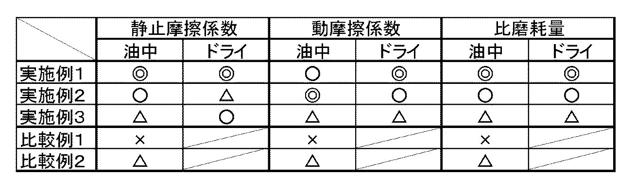
実施例1~実施例3に示す組成のCu-Ni-Si系合金は、何れも高硬度特性を示し、表1及び表2に示すように、油中環境下及びドライ環境下の何れであっても磨耗量が少ない。特に、実施例1と実施例2に示す組成のCu-Ni-Si系合金は、油中環境下で低摩擦及び低摩耗の特性を示す。更に、実施例1に示す組成のCu-Ni-Si系合金は、ドライ環境下であっても低摩擦及び低摩耗の特性を示す。
比較例1に示す組成のCu-Ni-Si系合金では、油中環境下であっても、焼き付きや磨耗が発生し、良好な摺動特性が得られない。一方、比較例2に示すPbを添加したCu-Ni-Si系合金では、油中環境下において焼き付きや磨耗が発生せず、良好な摺動特性が得られるものの、実施例3に示す組成のCu-Ni-Si系合金と同等程度の結果であった。
これに対し、実施例1~実施例3に示す組成のCu-Ni-Si系合金では、Pbを添加せずとも摩擦係数が低く抑えられて低摩擦の特性を示し、かつ、Pbを添加した摺動材料と比較して高硬度特性を持つことから比磨耗量が低く抑えられて低摩耗の特性を示しており、Pbを添加する以上に良好な摺動特性が得られる。これにより、本願発明では、良好な摺動特性を有する軸受用の摺動材料を、Pb(鉛)フリーで実現でき、高硬度特性を持つことから、高荷重が掛かる部位に適用しても、良好な摺動特性が得られる。
特に、実施例1に示す組成のCu-Ni-Si系合金は、油中環境下とドライ環境下の何れであっても、良好な低摩擦及び低摩耗の特性を示すので、油膜切れの起こるような境界潤滑状態等の部位に好適である。一方、実施例2に示す組成のCu-Ni-Si系合金は、油中環境下で良好な低摩擦及び低摩耗の特性を示すので、液体潤滑等、比較的油膜切れの起こりにくい部位に好適である。
ここで、実施例1~実施例3に示す組成のCu-Ni-Si系合金は、ビッカース硬さ(HV)が何れも200程度と高硬度特性を示す。ビッカース硬さ(HV)が150以上であれば、油圧機械の分野において、耐キャビテーション・エロージョン性に優れ、合金の浸食や疲労が起こり難くなる。
本発明の摺動材料は、ドライ環境下であっても、良好な低摩擦及び低摩耗の特性を示すので、油膜の形成し難い部位に使用される軸受にも適用可能である。
1・・・軸受用合金、2・・・軸受用複層金属材、3・・・基材金属、4・・・摺動材料、6・・・軸受用合金、7・・・軸受用複層金属材、8・・・基材金属
Claims (8)
- Niを0.5~10.0質量%、Siを0.1~5.0質量%、Crを0.1~5.0質量%含み、残部がCuと不可避的な不純物からなり、不純物レベルでSnを含む
ことを特徴とする摺動材料。 - Biを2.0~20.0質量%含む
ことを特徴とする請求項1記載の摺動材料。 - Niを0.5~10.0質量%、Siを0.1~5.0質量%、Crを0.1~5.0質量%含み、残部がCuと不可避的な不純物からなり、不純物レベルでSnを含む組成を有した粉末状の摺動材料が、所定の形状に成型されて焼結された
ことを特徴とする軸受用合金。 - 前記摺動材料は、Biを2.0~20.0質量%含む
ことを特徴とする請求項3記載の軸受用合金。 - Niを0.5~10.0質量%、Siを0.1~5.0質量%、Crを0.1~5.0質量%含み、残部がCuと不可避的な不純物からなり、不純物レベルでSnを含む組成の摺動材料で構成される軸受用合金が、基材金属の一の面に接合されて摺動面を構成した
ことを特徴とする軸受用複層金属材。 - 前記摺動材料は、Biを2.0~20.0質量%含む
ことを特徴とする請求項5記載の軸受用複層金属材。 - 前記軸受用合金は、粉末状の前記摺動材料が、所定の形状に成形されて焼結され、前記基材金属に接合される
ことを特徴とする請求項5または請求項6記載の軸受用複層金属材。 - 前記軸受用合金は、前記摺動材料が肉盛溶接で前記基材金属に接合される
ことを特徴とする請求項5または請求項6記載の軸受用複層金属材。
Applications Claiming Priority (2)
| Application Number | Priority Date | Filing Date | Title |
|---|---|---|---|
| JP2011-097302 | 2011-04-25 | ||
| JP2011097302A JP2012229465A (ja) | 2011-04-25 | 2011-04-25 | 摺動材料、軸受用合金及び軸受用複層金属材 |
Publications (1)
| Publication Number | Publication Date |
|---|---|
| WO2012147780A1 true WO2012147780A1 (ja) | 2012-11-01 |
Family
ID=47072298
Family Applications (1)
| Application Number | Title | Priority Date | Filing Date |
|---|---|---|---|
| PCT/JP2012/061071 Ceased WO2012147780A1 (ja) | 2011-04-25 | 2012-04-25 | 摺動材料、軸受用合金及び軸受用複層金属材 |
Country Status (2)
| Country | Link |
|---|---|
| JP (1) | JP2012229465A (ja) |
| WO (1) | WO2012147780A1 (ja) |
Cited By (2)
| Publication number | Priority date | Publication date | Assignee | Title |
|---|---|---|---|---|
| CN111705238A (zh) * | 2020-07-20 | 2020-09-25 | 华东交通大学 | 一种高强高导耐热铜合金材料 |
| CN112840052A (zh) * | 2018-03-27 | 2021-05-25 | 万腾荣公司 | 具有增强的导热性和耐磨性的铜合金组合物 |
Families Citing this family (7)
| Publication number | Priority date | Publication date | Assignee | Title |
|---|---|---|---|---|
| PL3565912T3 (pl) * | 2017-01-06 | 2021-10-11 | Materion Corporation | Pierścienie tłokowe uszczelniające ze stopów miedzi |
| DE102017001846B4 (de) * | 2017-02-25 | 2025-02-20 | Wieland-Werke Ag | Gleitelement aus einer Kupferlegierung |
| JP7126656B2 (ja) * | 2018-09-13 | 2022-08-29 | 三芳合金工業株式会社 | 極低温部材用銅合金 |
| WO2020090084A1 (ja) * | 2018-11-01 | 2020-05-07 | 日立化成株式会社 | 銅基焼結体の製造方法 |
| DE102018220056A1 (de) * | 2018-11-22 | 2020-05-28 | Ewellix AB | Präzisionsschienenherstellungsverfahren und Präzisionsschiene |
| CN111705237B (zh) * | 2020-06-03 | 2021-12-14 | 河海大学 | 一种船舶螺旋桨用耐腐蚀防污损抗空蚀铜基中熵合金涂层及其制备方法 |
| JPWO2024210037A1 (ja) * | 2023-04-05 | 2024-10-10 |
Citations (4)
| Publication number | Priority date | Publication date | Assignee | Title |
|---|---|---|---|---|
| JPH07310133A (ja) * | 1994-05-12 | 1995-11-28 | Chuetsu Gokin Chuko Kk | 無鉛快削黄銅合金 |
| JP2002302722A (ja) * | 2001-04-09 | 2002-10-18 | Chuetsu Metal Works Co Ltd | 高強度青銅系合金及びその製造方法 |
| JP2008223069A (ja) * | 2007-03-12 | 2008-09-25 | Miyoshi Gokin Kogyo Kk | 高強度高導電性銅合金及びその製造方法 |
| JP2010280984A (ja) * | 2009-06-08 | 2010-12-16 | Miyoshi Gokin Kogyo Kk | 発動機用摺動材に用いる銅合金の製造方法 |
-
2011
- 2011-04-25 JP JP2011097302A patent/JP2012229465A/ja not_active Withdrawn
-
2012
- 2012-04-25 WO PCT/JP2012/061071 patent/WO2012147780A1/ja not_active Ceased
Patent Citations (4)
| Publication number | Priority date | Publication date | Assignee | Title |
|---|---|---|---|---|
| JPH07310133A (ja) * | 1994-05-12 | 1995-11-28 | Chuetsu Gokin Chuko Kk | 無鉛快削黄銅合金 |
| JP2002302722A (ja) * | 2001-04-09 | 2002-10-18 | Chuetsu Metal Works Co Ltd | 高強度青銅系合金及びその製造方法 |
| JP2008223069A (ja) * | 2007-03-12 | 2008-09-25 | Miyoshi Gokin Kogyo Kk | 高強度高導電性銅合金及びその製造方法 |
| JP2010280984A (ja) * | 2009-06-08 | 2010-12-16 | Miyoshi Gokin Kogyo Kk | 発動機用摺動材に用いる銅合金の製造方法 |
Cited By (2)
| Publication number | Priority date | Publication date | Assignee | Title |
|---|---|---|---|---|
| CN112840052A (zh) * | 2018-03-27 | 2021-05-25 | 万腾荣公司 | 具有增强的导热性和耐磨性的铜合金组合物 |
| CN111705238A (zh) * | 2020-07-20 | 2020-09-25 | 华东交通大学 | 一种高强高导耐热铜合金材料 |
Also Published As
| Publication number | Publication date |
|---|---|
| JP2012229465A (ja) | 2012-11-22 |
Similar Documents
| Publication | Publication Date | Title |
|---|---|---|
| WO2012147780A1 (ja) | 摺動材料、軸受用合金及び軸受用複層金属材 | |
| JP3939931B2 (ja) | 銅系複層摺動材料 | |
| US6652675B2 (en) | Copper alloy sliding material | |
| CN102728839B (zh) | 不含Pb的铜合金滑动材料的制造方法 | |
| US6334914B2 (en) | Copper alloy sliding material | |
| US6692548B2 (en) | Copper-based sliding material, method of manufacturing the same, and sliding bearing | |
| JP4476634B2 (ja) | Pbフリー銅合金摺動材料 | |
| JP2010535287A (ja) | 耐摩耗性の鉛フリー合金ブッシングおよびその製造方法 | |
| CN102149833A (zh) | 不含Pb的Cu-Bi系烧结材料制得的滑动部件 | |
| JP2004277883A (ja) | 熱間加工アルミニウム合金、その合金から作られた基層と軸受素子 | |
| KR102672968B1 (ko) | 미끄럼 이동 부재, 베어링, 미끄럼 이동 부재의 제조 방법, 베어링의 제조 방법 | |
| US5482782A (en) | Sliding-contact material excellent in corrosion resistance and wear resistance, and method of manufacturing the same | |
| CN102027251A (zh) | 滑动轴承 | |
| US8703660B2 (en) | Lead-free sintered lubricating material and sinter powder for manufacture of the same | |
| US20100002968A1 (en) | Plain Bearing | |
| GB2489601A (en) | Sliding bearing with a layer of a copper-bismuth-tin-phosphorous alloy | |
| GB2263950A (en) | Bearings. | |
| KR20130021332A (ko) | 구리계 슬라이딩 재료 | |
| JP2002310158A (ja) | 複層摺動材料 | |
| JP4389026B2 (ja) | 摺動材料およびその製造方法 | |
| JP7125647B1 (ja) | 摺動部材および軸受 | |
| JP6363931B2 (ja) | すべり軸受用銅合金 | |
| CN102227569B (zh) | 轴承材料 | |
| JP5073925B2 (ja) | 鉛フリー銅系摺動材料 | |
| JP2006037179A (ja) | 耐焼付性に優れたPbフリー銅合金系複合摺動材 |
Legal Events
| Date | Code | Title | Description |
|---|---|---|---|
| 121 | Ep: the epo has been informed by wipo that ep was designated in this application |
Ref document number: 12776920 Country of ref document: EP Kind code of ref document: A1 |
|
| WA | Withdrawal of international application | ||
| NENP | Non-entry into the national phase |
Ref country code: DE |