WO2012147775A1 - 流体制御弁 - Google Patents
流体制御弁 Download PDFInfo
- Publication number
- WO2012147775A1 WO2012147775A1 PCT/JP2012/061057 JP2012061057W WO2012147775A1 WO 2012147775 A1 WO2012147775 A1 WO 2012147775A1 JP 2012061057 W JP2012061057 W JP 2012061057W WO 2012147775 A1 WO2012147775 A1 WO 2012147775A1
- Authority
- WO
- WIPO (PCT)
- Prior art keywords
- fluid control
- piston
- control valve
- knob
- cam member
- Prior art date
- Legal status (The legal status is an assumption and is not a legal conclusion. Google has not performed a legal analysis and makes no representation as to the accuracy of the status listed.)
- Ceased
Links
Images


Classifications
-
- F—MECHANICAL ENGINEERING; LIGHTING; HEATING; WEAPONS; BLASTING
- F16—ENGINEERING ELEMENTS AND UNITS; GENERAL MEASURES FOR PRODUCING AND MAINTAINING EFFECTIVE FUNCTIONING OF MACHINES OR INSTALLATIONS; THERMAL INSULATION IN GENERAL
- F16K—VALVES; TAPS; COCKS; ACTUATING-FLOATS; DEVICES FOR VENTING OR AERATING
- F16K31/00—Actuating devices; Operating means; Releasing devices
- F16K31/44—Mechanical actuating means
- F16K31/52—Mechanical actuating means with crank, eccentric, or cam
- F16K31/524—Mechanical actuating means with crank, eccentric, or cam with a cam
- F16K31/52491—Mechanical actuating means with crank, eccentric, or cam with a cam comprising a diaphragm cut-off apparatus
-
- F—MECHANICAL ENGINEERING; LIGHTING; HEATING; WEAPONS; BLASTING
- F16—ENGINEERING ELEMENTS AND UNITS; GENERAL MEASURES FOR PRODUCING AND MAINTAINING EFFECTIVE FUNCTIONING OF MACHINES OR INSTALLATIONS; THERMAL INSULATION IN GENERAL
- F16K—VALVES; TAPS; COCKS; ACTUATING-FLOATS; DEVICES FOR VENTING OR AERATING
- F16K7/00—Diaphragm valves or cut-off apparatus, e.g. with a member deformed, but not moved bodily, to close the passage ; Pinch valves
- F16K7/12—Diaphragm valves or cut-off apparatus, e.g. with a member deformed, but not moved bodily, to close the passage ; Pinch valves with flat, dished, or bowl-shaped diaphragm
- F16K7/14—Diaphragm valves or cut-off apparatus, e.g. with a member deformed, but not moved bodily, to close the passage ; Pinch valves with flat, dished, or bowl-shaped diaphragm arranged to be deformed against a flat seat
- F16K7/16—Diaphragm valves or cut-off apparatus, e.g. with a member deformed, but not moved bodily, to close the passage ; Pinch valves with flat, dished, or bowl-shaped diaphragm arranged to be deformed against a flat seat the diaphragm being mechanically actuated, e.g. by screw-spindle or cam
Definitions
- the present invention provides a valve seat formed in a fluid flow path that communicates between a first port and a second port, a valve body that contacts or separates from the valve seat and controls the flow of fluid, and the valve body And a knob that moves the piston in the opening / closing direction of the valve body.
- FIG. 22 is a cross-sectional view of the fluid control valve 300 described in Patent Document 1.
- the fluid control valve 300 includes a main shaft 303 having a valve body 302 that contacts or separates from the valve seat 301, and a spring 304 urges the main shaft 303 in a downward (valve closing) direction.
- the main shaft 303 is urged by a spring 304 to press-seal the valve body 302 against the valve seat 301.
- a handle 305 is formed in the fluid control valve 300, and a cam member 306 is fixed in the handle 305.
- the handle 305 is rotated, the main shaft 303 is raised by the cam member 306, and the valve body 302 is separated from the valve seat 301.
- two steel balls 307 are provided in the cam member 306, and the distance between the two steel balls 307 is narrowed when the handle 305 is rotated.
- a narrow taper portion is formed from the upper side to the lower side at a portion of the outer periphery of the main shaft 303 that contacts the two steel balls 307. Therefore, by rotating the handle 305, the interval between the two steel balls 307 is narrowed, and the main shaft 303 is raised in a form of lifting the tapered portion.
- Patent Documents 2 and 3 relate to a fluid control valve that does not use a cam member made by the present applicant. Since the cam member is not used, a detailed description is omitted.
- the prior art has the following problems. That is, the spring 304 is used to press-seal the valve body 302 against the valve seat 301 and is a spring having a high load (high repulsive force). Therefore, firstly, since the spring 304 has a high load, it is necessary to apply a very strong torque to rotate the handle 305 to narrow the distance between the two steel balls 307 and lift the main shaft 303. It becomes a problem. A strong torque can be applied by increasing the screwed portion of the handle and the main shaft and turning the handle a lot, but this is also problematic because the fluid control valve is enlarged. For this reason, most types on the market open the fluid control valve with a spring and close it manually (by human force).
- the two steel balls 307 lift the main shaft 303 with a small interval, it is necessary to increase the strength of the main shaft 303.
- the fluid control valve is made of resin, there is a problem that the fluid control valve is enlarged in order to increase the strength.
- the resin-made fluid control valve is originally weaker than metal, there is also a problem that it is easily damaged depending on the use situation.
- an object of the present invention is to provide a fluid control valve that can reduce the torque required for opening and closing the fluid control valve.
- a fluid control valve has the following configuration.
- a valve seat formed in a fluid flow path communicating with the first port and the second port; a valve body that contacts or separates from the valve seat to control the flow of fluid; and the valve body,
- a cam member to be connected to the knob is interposed between the knob and the piston,
- a cam surface having one of the concavo-convex shapes is formed on the abutting end surface of the cam member that abuts on the piston, and the concavo-convex shape is formed on the portion of the piston that abuts on the cam surface.
- the piston engaging part which has the other shape of these is formed, It is characterized by the above-mentioned.
- the fluid control valve can be opened and closed using the cam surface and the piston engaging portion, it is not necessary to increase the strength of the fluid control valve as compared with the case of using a steel ball as in the prior art. Therefore, since all the materials of the fluid control valve can be made of resin, an increase in the size of the fluid control valve can be prevented.
- the operator can easily open and close the fluid control valve because the fluid control valve can be opened and closed by a single simple operation that allows the operator to rotate the knob and the cam member with less rotation. .
- the fluid control valve can be opened and closed with one simple operation that requires only a small amount of rotation, the torque required for operation can be reduced.
- the inclination of the cam member can be suppressed.
- the load per site on the cam surface can be reduced, so that the operator can easily open and close the fluid control valve. That is, since the cam member is stabilized by being formed at two or more locations on the cam surface in contact with the piston, the inclination of the cam member can be suppressed.
- the valve body can be pressed against the valve seat with an equal torque. Therefore, the sealing force can be uniformly applied to the valve body, and the sealing can be performed reliably.
- the durability of the cam can be improved, and the durability of the fluid control valve having the cam can be improved.
- the cam surface has a tapered surface having an inclination angle of 2 or more.
- the torque applied to the knob can be changed by the inclination angle.
- the torque applied to the knob is reduced as a result.
- the torque applied to the knob can be reduced by setting the inclination angle during the second half rotation of the knob to which the torque is applied to a gentle angle. Therefore, the torque for rotating the knob can be reduced throughout.
- the fluid control valve is configured so that the valve and the cam member are rotated about 90 degrees, and the valve seat is moved to the valve seat. It is preferred that the body abuts or separates.
- valve body can contact or separate from the valve seat. Since the fluid control valve can be opened and closed by a simple operation that only rotates about 90 degrees, the torque required for the operation can be reduced.
- the fluid control valve can be opened and closed by turning about 90 degrees, it can be recognized at a glance whether the knob is open or closed simply by looking at the direction of the knob. Since the open / closed state can be confirmed at a glance, the operator's confirmation work is facilitated, and the cost for confirmation can be reduced.
- the piston engages with the piston engaging portion when the piston slides in the closing direction on the contact end surface of the cam member. It is preferable that an abutting end surface engaging portion is formed.
- the fluid control valve can be maintained in an open state or a closed state. That is, the piston and the cam are maintained by the engagement of the piston engaging portion of the piston and the contact end surface engaging portion of the cam.
- the fluid control valve can be maintained in the fully open state or the fully closed state.
- the knob is smaller than an outer dimension of a valve body in which the cam member is incorporated.
- the fluid control valve can be opened and closed simply by rotating the knob by, for example, about 90 degrees, the torque required for the operator to rotate the knob can be reduced. Therefore, the knob can be reduced in size, and the fluid control valve can be reduced in size.
- the movement of the piston can be replaced with the driving by the knob, and the driving of the motor or the cylinder can be reduced by using the motor driving or the cylinder driving. Therefore, a motor or a cylinder can be reduced in size.
- the drive source is a motor
- the operation torque can be reduced by using a cam member and a piston. Therefore, when the drive source is a motor, the motor can be operated with a small amount of electric power, so that energy can be saved. Similarly, when a cylinder is used, the air output can be reduced, so that energy can be saved.
- cam member It is an external appearance upper perspective view of the cam member concerning this example 1 of the present invention. It is the side view which looked at the cam member shown in Drawing 5 concerning this example 1 of the present invention from the B direction. It is an appearance bottom perspective view of a cam member concerning this example 1 of the present invention. It is a top view of the piston which concerns on the present Example 1 of this invention. It is sectional drawing of the fluid control valve (at the time of full open) which concerns on the present Example 2 of this invention. It is sectional drawing of the fluid control valve (when fully closed) which concerns on the present Example 2 of this invention. It is a top view of the cam member which concerns on the present Example 2 of this invention.
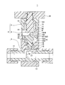
- FIG. 1 shows a cross-sectional view of the fluid control valve 1 (when fully opened).
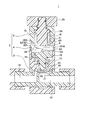
- FIG. 2 is a cross-sectional view of the fluid control valve 1 (during the first operation).
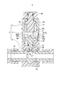
- FIG. 3 shows a cross-sectional view of the fluid control valve 1 (during the second operation).
- FIG. 4 shows a cross-sectional view of the fluid control valve 1 (when fully closed).
- the fluid control valve is described as a manual valve, but the drive source may be electric other than manual, air, or the like.
- the fluid control valve 1 of the present embodiment is used as one of fluid control devices of a semiconductor manufacturing apparatus. As shown in FIG. 1, the valve body 2 of the fluid control valve 1 is obtained by connecting a body part 3, a cylinder 4, a cover 5, and the like. The body part 3, the cylinder 4 and the cover 5 are made of resin.
- the body part 3 is formed with a first port 13 and a second port 14, and a valve hole 17 is provided in a valve chamber 18 that connects them.
- a convex valve seat 16 is circumferentially formed on the peripheral edge of the valve hole 17.
- the diaphragm valve body 15 has a peripheral portion sandwiched between the body portion 3 and the cylinder 4, and one end of the piston 10 is screwed to the center portion.
- the piston 10 is formed by joining a large cylindrical portion 102 and a small cylindrical portion 103 shown in FIG.
- the large cylindrical portion 102 is formed on the cam member 6 side, and the small cylindrical portion 103 is formed on the valve seat 16 side.
- the piston 10 is disposed in a substantially hollow cylindrical portion 41 formed in the cylinder 4 so as to be slidable in the vertical direction.
- One end of the small cylindrical portion 103 of the piston 10 is screwed to the diaphragm valve body 15, and the large cylindrical portion 102 is in contact with the cam member 6.
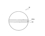
- a convex piston engaging portion 101 is formed in a portion of the large cylindrical portion 102 of the piston 10 that comes into contact with the cam member 6.
- the piston engaging portion 101 has a triangular cross section having a tip portion 101A.
- FIG. 11 shows a top view of the piston 10. As shown in FIG. 11, the piston engaging portion 101 of the piston 10 is formed so as to cross the center of the upper surface of the piston 10.
- one end of the second urging member 12 is fixed to the surface of the large cylindrical portion 102 opposite to the surface in contact with the cam member 6 in FIG.
- the other end of the second urging member 12 is fixed to the cylinder 4. Therefore, the piston 10 is urged toward the knob 20 by the second urging member 12. Therefore, the piston engaging portion 101 of the piston 10 is in contact with the cam surface 62.
- the piston engaging portion 101 has a convex shape.
- the cam surface 62 has a convex shape
- the piston engaging portion 101 has a concave shape.
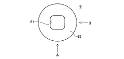
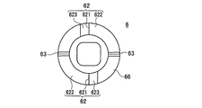
- FIG. 5 shows a top view of the cam member 6.
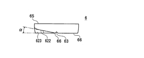
- FIG. 6 shows a side view of the cam member 6 shown in FIG.
- FIG. 7 shows a bottom view of the cam member 6.
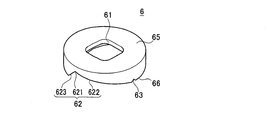
- FIG. 8 the external appearance upper perspective view of the cam member 6 is shown.
- FIG. 9 shows a side view of the cam member 6 shown in FIG.
- FIG. 10 shows an external lower perspective view of the cam member 6.
- the cam member 6 is disposed in a substantially hollow cylindrical portion 41 formed in the cylinder 4 so as to be rotatable. As shown in FIGS. 8 and 10, the cam member 6 has a substantially cylindrical shape.
- the lower surface of the cylindrical portion of the cam member 6 is an abutting end surface 66 that contacts the piston 10, and the upper surface of the cylindrical portion of the cam member 6 is a connecting end surface 65 that is connected to the knob connecting member 19.
- the contact end surface 66 and the connecting end surface 65 are parallel surfaces.
- the contact end surface 66 is formed with a cam surface 62 having an uneven shape and a contact end surface engaging portion 63 that engages with the piston engaging portion 101 of the piston 10.
- the cam surface 62 has a bottom portion 621, a sliding taper surface 622, and a relief portion taper surface 623.
- the bottom portion 621 is formed at a portion deepest from the contact end surface 66. Further, a tapered sliding taper surface 622 and a relief taper surface 623 continue from the bottom 621 toward the contact end surface 66.
- the sliding taper surface 622 is a surface on which the piston engaging portion 101 of the piston 10 comes into contact and slides.
- the relief portion taper surface 623 is a surface that does not come into contact with the piston engaging portion 101 of the piston 10.
- the angle ⁇ of the sliding tapered surface 622 with respect to the contact end surface 66 is about 15 degrees in the present embodiment. By setting the angle ⁇ to a loose angle of about 15 degrees, it is possible to reduce the torque when the knob 20 is rotated and the piston 10 is moved downward (valve closed).
- the angle ⁇ is set to about 15 degrees.
- the angle ⁇ is preferably as small as possible.
- the abutting end surface engaging portion 63 is formed following the sliding tapered surface 622.
- the abutting end surface engaging portion 63 is formed for engaging and fixing the piston 10 and is for maintaining the piston 10 so as not to return to the sliding tapered surface 622.
- a substantially rectangular insertion hole 61 into which the knob coupling member 19 is inserted is formed at the center of the coupling end surface 65.
- it has a substantially rectangular shape, but may be any polygonal shape that can engage with the knob connecting member 19.
- one end of the first urging member 11 is engaged with the connecting end surface 65.
- the other end of the first urging member 11 is engaged with an urging member fixing portion 191 formed on the knob connecting member 19. Therefore, the cam member 6 is urged toward the valve seat 16 by the first urging member 11. Therefore, the cam member 6 is in contact with the piston engaging portion 101 of the piston 10.
- the cam member 6 is in contact with an inner cylinder step portion 42 formed in the cylinder 4, and the cam member 6 moves in a lower (valve closing) direction than the inner cylinder step portion 42. I can't.
- the cam surface 62 has a concave shape, but when the piston engaging portion 101 has a convex shape, the cam surface 62 has a convex shape.
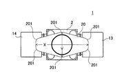
- FIG. 20 shows a top view of the fluid control valve 1 (when fully opened).
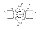
- FIG. 21 shows a top view of the fluid control valve 1 (when fully closed).
- a knob 20 that can be rotated about 90 degrees is formed at the upper end of the fluid control valve 1.
- the knob 20 has a vertically long hexagonal shape having a major axis X and a minor axis Y. Since the knob 20 has a hexagonal shape, corner portions 201 are formed at six locations. By forming the corner portions 201 at six locations, the knob 20 can be rotated without the operator sliding his / her hand.
- the knob 20 has a vertically long shape having a major axis X and a minor axis Y as shown in FIG. Therefore, when the valve is open as shown in FIG. 20, the long axis X of the knob 20 is on the same line as the first port 13 and the second port 14. When the valve is closed in FIG. 21, the long axis X of the knob 20 is on a line perpendicular to the first port 13 and the second port 14. Therefore, it can be recognized at a glance that the position of the knob 20 is different between when the valve is closed and when the valve is opened. Therefore, since the operator can recognize the open / closed state of the fluid control valve 1 at a glance, the time for the confirmation work can be shortened, and the cost for the confirmation work can be reduced.
- the knob 20 can be reduced in size.
- the knob 20 can be reduced in size, for example, although not shown, the major axis X and the minor axis Y of the knob 20 can be made smaller than the outer dimensions of the valve body 2 in which the cam member 6 is built. By making the knob 20 smaller than the outer dimension of the valve main body 2, it does not protrude from the projected area of the valve main body 2 in either the valve open state or the valve closed state. Therefore, the fluid control valve 1 can be reduced in size. Since the fluid control valve 1 can be reduced in size, space saving can be achieved when a manifold (continuous connection) is used.
- the upper end of the knob connecting member 19 is fixedly connected to the center of the knob 20.
- the knob connecting member 19 has a substantially cylindrical shape.
- the knob connecting member 19 is fixedly connected to the central portion of the knob 20 and has a substantially cylindrical shape. Therefore, when the knob 20 is rotated, the knob connecting member 19 rotates in conjunction with the knob 20.
- the knob connecting member 19 is disposed in a rotatable state in the hollow portion 51 in the cover 5.
- the shape of the lower end of the knob connecting member 19 is a square shape. The lower end of the knob connecting member 19 is inserted into an insertion hole 61 formed at the center of the cam member 6.
- knob connecting member 19 and the cam 6 can be rotated in conjunction with each other by adopting a shape that matches the polygonal shape of the insertion hole 61 of the cam 6.
- a biasing member fixing portion 191 is formed on the cylindrical side surface of the knob connecting member 19 in a circumferential shape, and one end of the first biasing member 11 is engaged with the biasing member fixing portion 191. The other end of the first urging member 11 is engaged with the connecting end surface 65 of the cam member 6.
- the urging force of the first urging member 11 is for pressing the diaphragm valve body 15 fixed to the piston 10 against the valve seat 16.
- the biasing force of the second biasing member 12 is for pressing the piston 10 against the cam member 6.
- the first urging member 11 overcomes the urging force of the second urging member 12 below in FIG. 1 and presses the diaphragm valve body 15 against the valve seat 16. Therefore, the urging force of the first urging member 11 is larger than the urging force of the second urging member 12.
- the 1st biasing member 11 and the 2nd biasing member 12 are using the metal spring member which has elastic force in this embodiment.
- the first biasing member 11 that biases the cam member 6 is in the most extended state, and the cam member 6 biased by the first biasing member 11 is in the lowest position. Therefore, in FIG. 1, the cam member 6 is in contact with an inner cylinder step portion 42 formed in the cylinder 4, and the cam member 6 is in a lower (valve closing) direction than the inner cylinder step portion 42. Is incapable of moving. Since the cam member 6 is in contact with the inner cylinder step portion 42 and the piston engaging portion 101 of the piston 10 is in contact with the bottom portion 621 of the cam surface 62, the first biasing member 11 The biasing force is not transmitted to the piston 10. Therefore, since the piston 10 is pressed by the cam member 6 and does not move toward the valve seat 16, the diaphragm valve body 15 is in a state of being separated from the valve seat 16. Therefore, the fluid control valve 1 is in a fully open state.
- the fluid control valve 1 shown in FIG. 2 is when the valve seat 16 and the diaphragm valve body 15 start to come into contact with each other from the fully open state to the fully closed state.
- the knob 20 rotates about 70 degrees clockwise in the drawing in the present embodiment.
- the knob connecting member 19 fixed to the knob 20 is rotated, and the cam member 6 to be engaged is similarly rotated about 70 degrees.
- the knob 20 is further rotated from the state shown in FIG. 2 so that the knob 20 in FIG. 3 is rotated about 87 degrees.
- the piston engaging portion 101 is in a state immediately before being engaged with the contact end surface engaging portion 63.
- the position of the piston 10 hardly changes.
- the knob 20 is rotated from the state of FIG. 2 to the state of FIG. 3, the cam member 6 is pressed by the piston 10 and moves toward the knob 20.
- the first urging member 11 has a structure that is compressed only when the knob 20 is rotated about 70 degrees or more shown in FIG. Accordingly, the first urging member 11 having a high load may be compressed after the knob 20 is rotated about 70 degrees. Therefore, a large torque is required only after the knob 20 has been rotated about 70 degrees. Therefore, since the range where the operation torque is required can be reduced, the operator's force is small, and workability can be further improved.
- the first urging member 11 is compressed only when the knob 20 is rotated by about 70 degrees or more.
- the knob 20 is rotated about 90 degrees.
- the first urging member 11 can be compressed. Thereby, it is possible to further reduce the range where the operation torque is required.
- the knob 20 is further rotated from the state shown in FIG. 3 to the state rotated about 90 degrees in FIG.
- the piston engaging portion 101 is engaged with the abutting end surface engaging portion 63.
- the first biasing member 11 presses the cam member 6 and presses the piston 10 toward the valve seat 16. Therefore, the diaphragm valve body 15 can be pressed against the valve seat 16 by the load of the first urging member 11, and a stable sealing force can be maintained.
- the piston engaging portion 101 is engaged with the contact end surface engaging portion 63, it can be maintained in the fully closed state shown in FIG. That is, the piston 10 and the cam member 6 cannot be moved from the position shown in FIG. 4 because the piston engaging portion 101 and the abutting end surface engaging portion 63 are engaged. Can do.
- the valve seat 16 and the diaphragm valve body 15 can be brought into contact with or separated from each other. That is, since the fluid control valve can be opened and closed by a simple operation in which the operator rotates the knob 20 by about 90 degrees, the fluid control valve 1 can be easily opened and closed. Furthermore, since the fluid control valve 1 can be opened and closed by a simple operation that only rotates about 90 degrees, the torque required for the operation can be reduced.
- the fluid control valve 200 according to the second embodiment shown in FIGS. 12 and 13 is different from the fluid control valve 1 according to the first embodiment shown in FIGS. 1 to 4 except for the shape of the cam member and the piston. Absent. Therefore, in 2nd Embodiment, the other detailed description is omitted by demonstrating the cam member 206 and piston 210 different from 1st Embodiment.
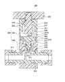
- FIG. 12 shows a cross-sectional view of the fluid control valve 200 (when fully opened).
- FIG. 13 shows a cross-sectional view of the fluid control valve 200 (when fully closed).
- the fluid control valve 200 is described as a manual valve, but the drive source may be electric other than manual, air, or the like.
- FIG. 19 shows a top view of the piston 210.
- the piston 210 in the second embodiment differs from the piston 10 in the first embodiment in the number of piston engaging portions 211. That is, the piston engaging portion 101 of the piston 10 of the first embodiment appeared in two places with respect to the outer periphery, but the piston engaging portion 211 of the piston 210 of the second embodiment has four with respect to the outer periphery. It appears in places.
- two piston engaging portions 211 are formed so as to cross the center of the upper surface of the piston 210.
- the piston engaging portions 211 of the piston 210 are formed at four positions with respect to the outer peripheral surface at intervals of 90 degrees.
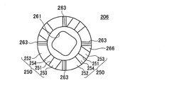
- FIG. 14 shows a top view of the cam member 206.
- FIG. 15 is a side view of the cam member 206 shown in FIG. 14 viewed from the C direction.
- FIG. 16 shows a bottom view of the cam member 206.
- FIG. 17 shows an upper perspective view of the appearance of the cam member 206.
- FIG. 18 is an external perspective view of the cam member 206.
- the cam member 206 in the second embodiment is different from the cam member 6 in the first embodiment in the number of contact end surface engaging portions 263 and the shape and number of the cam surface 250.
- the contact end surface engaging portions 263 are uniformly formed at intervals of 90 degrees with respect to the contact end surface 266 that is the lower surface of the cylindrical portion of the cam member 206. Since the contact end surface engaging portions 263 are formed at intervals of 90 degrees, they are formed at four locations over the entire circumference.
- the cam surface 250 has a bottom portion 251, a sliding tapered surface 252, a relief tapered surface 253, and a connecting tapered surface 254.
- the cam surface 250 is uniformly formed at intervals of 90 degrees with respect to the contact end surface 266. Since the cam surface 250 is formed at intervals of 90 degrees, it is formed at four locations over the entire circumference.
- the bottom portion 251 is formed in a portion deepest from the contact end surface 266. Further, one end of the tapered relief portion taper surface 253 and the connecting taper surface 254 is connected from the bottom portion 251 toward the contact end surface 266. The other end of the connecting tapered surface 254 is connected to the sliding tapered surface 252. The other end of the sliding taper surface 252 is connected to the contact end surface 266.
- connection taper surface 254 and the sliding taper surface 252 are surfaces on which the piston engaging portion 211 of the piston 210 comes into contact and slides.
- the relief portion taper surface 253 is a surface that does not come into contact with the piston engaging portion 211 of the piston 210.
- the angle ⁇ of the sliding tapered surface 252 with respect to the contact end surface 266 is about 15 degrees.
- the torque when the knob 220 is rotated and the piston 210 is moved downward (valve closed) can be reduced. That is, this is because the torque applied can be reduced by making the range in which the first urging member 211 is compressed a gentle angle. Thereby, the operation torque can be reduced and the operability can be improved.
- the cam surfaces are formed at two or more places as in the second embodiment, even if the connecting tapered surface 254 is formed, the sliding force of about 15 degrees is within the range in which the first biasing member 211 is compressed. If the dynamic taper surface 252 can be formed, the torque can be reduced.
- the angle ⁇ of the connecting tapered surface 254 with respect to the contact end surface 266 is about 40 degrees.
- the piston engaging portion 211 slides on the connecting tapered surface 254 until the knob 220 rotates about 70 degrees.
- the time until the knob 220 rotates about 70 degrees is the time until the diaphragm valve body 15 starts to contact the valve seat 16.
- the biasing force of the first biasing member 11 is greater than the biasing force of the second biasing member 12. Therefore, even if the angle ⁇ of the connecting tapered surface 254 with respect to the contact end surface 266 is a steep angle of about 40 degrees, the torque applied to the knob 220 by the operator can be small.
- the reason why the angle ⁇ can be set to a gentle angle of about 15 degrees is that the cam surface 250 is formed on the outer periphery of the cylindrical portion of the cam member 206. This is because the distance can be increased by forming the cam surface 250 on the outer periphery of the cylindrical portion, so that the angle can be relaxed. Further, this is because the angle ⁇ of the connecting tapered surface 254 is steep.
- the fluid control valve 200 in the second embodiment has the same operation effects as the fluid control valve 1 in the first embodiment, and also has the following specific operation effects.
- the cam member 206 When the fluid control valve 200 moves from the open state shown in FIG. 12 to the closed state shown in FIG. 13, the cam member 206 is similarly rotated by rotating the knob 220. As the cam member 206 rotates, the piston 210 that contacts the cam surface 250 of the cam member 206 moves. In the fluid control valve 200, the cam surface 250 and the piston engaging portion 211 of the piston 210 are in contact with each other at four locations over the entire circumference. Therefore, when the piston 210 moves in the direction of the valve seat 216, the four piston engaging portions 211 are moved by being pressed by the four cam surfaces 250. The piston 210 can be moved in parallel by pressing four piston engaging portions 211 formed at equal intervals of 90 degrees in the piston 210.
- the diaphragm valve body 215 screwed to the piston 210 can also be pressed and moved in parallel with an equal torque, it is pressed against the valve seat 216 with an equal torque. Therefore, the diaphragm valve body 215 can be reliably sealed with respect to the valve seat 216. Further, the cam member 206 can be prevented from being inclined by being pressed at four positions.
- the cam surface 250 has a sliding taper surface 252 and a connecting taper surface 254 having an inclination angle ⁇ . Therefore, the piston engaging portion 211 slides on the connecting tapered surface 254 until the knob 220 is rotated about 70 degrees.
- the connecting tapered surface 254 the urging force of the first urging member 11 is greater than the urging force of the second urging member 12 until the diaphragm valve body 15 starts to contact the valve seat 16.
- the torque applied by the knob 220 can be small. Therefore, even if the angle ⁇ of the connecting tapered surface 254 with respect to the contact end surface 266 is a steep angle of about 40 degrees, the torque applied to the knob 220 by the operator can be small.
- the sliding taper surface 252 is a range in which the first urging member 211 is compressed, and the range can be set to a gentle angle, so that the torque can be reduced. Thereby, the operation torque can be reduced and the operability can be improved.
- the torque applied to the knob 220 can be changed by the inclination angle by making the cam surface 250 a tapered surface having an inclination angle of 2 or more.
- the torque applied to the knob 220 is reduced as a result of setting the inclination angle until the knob 220 to which no torque is applied to about 70 degrees is a steep angle.
- the torque applied to the knob 220 can be reduced by setting the inclination angle when the knob 220 to which the torque is applied is rotated by about 70 degrees or more to a gentle angle. Therefore, the torque for rotating the knob 220 can be reduced throughout.
- the angle ⁇ and the angle ⁇ can be changed according to the embodiment.
- the torque applied to the knob can be changed by changing the angle ⁇ and the angle ⁇ .
- the cam surface 250 by forming the cam surface 250 at four places, the load at one place for pressing the piston 210 is reduced. By forming the cam surface 250 at four locations, the load per location on the cam surface 250 can be reduced, so that the operator can easily open and close the fluid control valve 1. That is, since the cam surface 250 that contacts the piston 210 is formed at four locations on the outer periphery, the cam member 206 is stabilized, so that the inclination of the cam member 206 can be suppressed. When the cam member 206 is stabilized, the valve body 15 can be pressed against the valve seat 16 with equal torque. Therefore, the sealing force can be uniformly applied to the valve body 15 and the sealing can be surely performed.
- the durability of the cam member 206 can be improved, and the durability of the fluid control valve 1 having the cam member 206 can be improved.
- the fluid control valve is a manual valve and the drive source is manually operated to rotate the knob.
- the drive source is electrically driven as a modification
- the operation torque can be reduced by using the cam member and the piston of the above embodiment. Therefore, when the drive source is electric, the motor can be operated with a small amount of electric power, so that energy can be saved. Further, when an air cylinder is used, the air output can be similarly reduced, so that energy can be saved.
- the drive source is electric or cylinder, it is not a manual valve, so it is replaced with a motor or cylinder instead of a knob.
- two or four cams are formed on the cam member 6, but one or three cams may be provided.
- the cam comes into contact with one place to move the piston, and the force of the operator is required. Since the pressing force applied to the piston by the cam can be dispersed by abutting at two or more locations, the operator's force can be reduced. Further, when the piston is moved to come into contact with the cam at one place, the piston cannot be pressed with an equal torque. If the piston cannot be pressed with an equal torque, the valve body cannot be pressed against the valve seat with an equal torque, and the entire circumference of the valve seat cannot be sealed uniformly. Therefore, two or more cams are required.
- the shape of the knob 20 is a hexagonal shape, but the shape of the knob 20 is a shape that fits within the projected area of the valve body 2 and has a vertically long shape. It may be a shape. For example, an elliptical shape, a rectangular shape, or a polygonal shape may be used.
- a contact end surface engaging portion is formed on the cam member
- a convex portion is formed on the piston
- the fluid control valve is opened or closed by engaging the convex portion with the contact end surface engaging portion.
- two or more cam surfaces are formed on the outer periphery of the cam member, but the cam surface may be formed on the inner periphery other than the outer periphery depending on the design conditions. Since the cam surface is positioned on the outer periphery of the cam member, the contact portion between the cam surface and the piston can be brought to the outer periphery, so that the cam can be stabilized.
- the fluid control valve can be opened and closed by turning the knob and the cam member about 90 degrees, but the turning angle of the knob and the cam member is changed by the design. can do. That is, the rotation angle of the knob and the cam member is determined by the inclination angle of the sliding taper surface. Increasing the inclination angle decreases the rotation angle at which the knob and the cam member rotate, and decreasing the inclination angle increases the rotation angle at which the knob and the cam member rotate. Therefore, the rotation angle of the knob and the cam member can be changed by changing the design of the inclination angle.
- the design change of the inclination angle is changed by the biasing member because the degree of operation torque applied varies depending on the biasing member used for the fluid control valve.
Landscapes
- Engineering & Computer Science (AREA)
- General Engineering & Computer Science (AREA)
- Mechanical Engineering (AREA)
- Mechanically-Actuated Valves (AREA)
- Electrically Driven Valve-Operating Means (AREA)
- Fluid-Driven Valves (AREA)
Applications Claiming Priority (2)
| Application Number | Priority Date | Filing Date | Title |
|---|---|---|---|
| JP2011098743A JP5602673B2 (ja) | 2011-04-26 | 2011-04-26 | 流体制御弁 |
| JP2011-098743 | 2011-04-26 |
Publications (1)
| Publication Number | Publication Date |
|---|---|
| WO2012147775A1 true WO2012147775A1 (ja) | 2012-11-01 |
Family
ID=47072293
Family Applications (1)
| Application Number | Title | Priority Date | Filing Date |
|---|---|---|---|
| PCT/JP2012/061057 Ceased WO2012147775A1 (ja) | 2011-04-26 | 2012-04-25 | 流体制御弁 |
Country Status (2)
| Country | Link |
|---|---|
| JP (1) | JP5602673B2 (enExample) |
| WO (1) | WO2012147775A1 (enExample) |
Cited By (1)
| Publication number | Priority date | Publication date | Assignee | Title |
|---|---|---|---|---|
| US12510170B2 (en) * | 2023-02-22 | 2025-12-30 | Koscn Industrial Manufacturing (shenzhen) Co., Ltd. | Diaphragm switch valve and assembly method for same |
Families Citing this family (2)
| Publication number | Priority date | Publication date | Assignee | Title |
|---|---|---|---|---|
| KR102331094B1 (ko) * | 2020-09-28 | 2021-12-01 | 김창호 | 위생도기용 급수장치 |
| CN222026318U (zh) * | 2024-03-08 | 2024-11-19 | 深圳市英维克智能连接技术有限公司 | 流体连接器及液冷装置 |
Citations (4)
| Publication number | Priority date | Publication date | Assignee | Title |
|---|---|---|---|---|
| DE693636C (de) * | 1936-04-25 | 1940-07-16 | Auergesellschaft Akt Ges | Von Hand betaetigtes Zusatzluftventil an Hoehenatemgeraeten |
| US2606450A (en) * | 1949-12-08 | 1952-08-12 | Crane Co | Valve actuating mechanism |
| JPS5590863U (enExample) * | 1978-12-18 | 1980-06-23 | ||
| EP0424782A1 (en) * | 1989-10-18 | 1991-05-02 | Kohler Co. | Self closing valve assembly |
-
2011
- 2011-04-26 JP JP2011098743A patent/JP5602673B2/ja not_active Expired - Fee Related
-
2012
- 2012-04-25 WO PCT/JP2012/061057 patent/WO2012147775A1/ja not_active Ceased
Patent Citations (4)
| Publication number | Priority date | Publication date | Assignee | Title |
|---|---|---|---|---|
| DE693636C (de) * | 1936-04-25 | 1940-07-16 | Auergesellschaft Akt Ges | Von Hand betaetigtes Zusatzluftventil an Hoehenatemgeraeten |
| US2606450A (en) * | 1949-12-08 | 1952-08-12 | Crane Co | Valve actuating mechanism |
| JPS5590863U (enExample) * | 1978-12-18 | 1980-06-23 | ||
| EP0424782A1 (en) * | 1989-10-18 | 1991-05-02 | Kohler Co. | Self closing valve assembly |
Cited By (1)
| Publication number | Priority date | Publication date | Assignee | Title |
|---|---|---|---|---|
| US12510170B2 (en) * | 2023-02-22 | 2025-12-30 | Koscn Industrial Manufacturing (shenzhen) Co., Ltd. | Diaphragm switch valve and assembly method for same |
Also Published As
| Publication number | Publication date |
|---|---|
| JP2012229755A (ja) | 2012-11-22 |
| JP5602673B2 (ja) | 2014-10-08 |
Similar Documents
| Publication | Publication Date | Title |
|---|---|---|
| JP6774931B2 (ja) | 二重駆動を有するアクチュエータ | |
| CA2984745C (en) | A mechanical energized sealing ball valve | |
| KR102270597B1 (ko) | 진공밸브 | |
| WO2017202151A1 (zh) | 一种强制密封球阀 | |
| JP6951706B2 (ja) | 流路切換弁およびその組立方法 | |
| JP6594007B2 (ja) | 真空バルブ | |
| JP6753937B2 (ja) | バルブ | |
| CN219062116U (zh) | 枢轴致动器 | |
| ATE528575T1 (de) | Anordnung aus einem hahn und einer schutzkappe sowie flasche mit einer solchen anordnung | |
| KR20050058440A (ko) | 핀치밸브 | |
| JP5602673B2 (ja) | 流体制御弁 | |
| KR20150108928A (ko) | 유체 분사 밸브용 밸브 조립체 및 유체 분사 밸브 | |
| US5957428A (en) | Composite-action butterfly valve | |
| CA2908438C (en) | Rotatable control device with axial translation | |
| RU2010125714A (ru) | Диафрагма с кольцевым уплотнением | |
| CN1671986A (zh) | 回转阀的执行机构 | |
| CN108351043B (zh) | 具有滑道驱动机构的真空角阀 | |
| CN102333981B (zh) | 用于具有气动锁定器件的阀的液压气动控制的装置 | |
| WO2005093306A1 (ja) | トルクリミッター付きハンドル及びこのハンドルを備えた流体制御器 | |
| JP5319969B2 (ja) | ボールバルブ | |
| US20100101408A1 (en) | Rotary actuator | |
| JP5850876B2 (ja) | ボールバルブ | |
| JP2012229755A5 (enExample) | ||
| JP6402313B2 (ja) | バタフライバルブ | |
| JP2012013142A (ja) | バルブ作動機取付構造 |
Legal Events
| Date | Code | Title | Description |
|---|---|---|---|
| 121 | Ep: the epo has been informed by wipo that ep was designated in this application |
Ref document number: 12775931 Country of ref document: EP Kind code of ref document: A1 |
|
| NENP | Non-entry into the national phase |
Ref country code: DE |
|
| 122 | Ep: pct application non-entry in european phase |
Ref document number: 12775931 Country of ref document: EP Kind code of ref document: A1 |