WO2012147591A1 - クランプ装置用防振材 - Google Patents
クランプ装置用防振材 Download PDFInfo
- Publication number
- WO2012147591A1 WO2012147591A1 PCT/JP2012/060492 JP2012060492W WO2012147591A1 WO 2012147591 A1 WO2012147591 A1 WO 2012147591A1 JP 2012060492 W JP2012060492 W JP 2012060492W WO 2012147591 A1 WO2012147591 A1 WO 2012147591A1
- Authority
- WO
- WIPO (PCT)
- Prior art keywords
- vibration
- cell bodies
- adjacent
- clamp
- integrally connected
- Prior art date
- Legal status (The legal status is an assumption and is not a legal conclusion. Google has not performed a legal analysis and makes no representation as to the accuracy of the status listed.)
- Ceased
Links
Images



Classifications
-
- F—MECHANICAL ENGINEERING; LIGHTING; HEATING; WEAPONS; BLASTING
- F16—ENGINEERING ELEMENTS AND UNITS; GENERAL MEASURES FOR PRODUCING AND MAINTAINING EFFECTIVE FUNCTIONING OF MACHINES OR INSTALLATIONS; THERMAL INSULATION IN GENERAL
- F16L—PIPES; JOINTS OR FITTINGS FOR PIPES; SUPPORTS FOR PIPES, CABLES OR PROTECTIVE TUBING; MEANS FOR THERMAL INSULATION IN GENERAL
- F16L3/00—Supports for pipes, cables or protective tubing, e.g. hangers, holders, clamps, cleats, clips, brackets
- F16L3/22—Supports for pipes, cables or protective tubing, e.g. hangers, holders, clamps, cleats, clips, brackets specially adapted for supporting a number of parallel pipes at intervals
- F16L3/223—Supports for pipes, cables or protective tubing, e.g. hangers, holders, clamps, cleats, clips, brackets specially adapted for supporting a number of parallel pipes at intervals each support having one transverse base for supporting the pipes
- F16L3/2235—Supports for pipes, cables or protective tubing, e.g. hangers, holders, clamps, cleats, clips, brackets specially adapted for supporting a number of parallel pipes at intervals each support having one transverse base for supporting the pipes each pipe being supported by a common element fastened to the base
-
- F—MECHANICAL ENGINEERING; LIGHTING; HEATING; WEAPONS; BLASTING
- F16—ENGINEERING ELEMENTS AND UNITS; GENERAL MEASURES FOR PRODUCING AND MAINTAINING EFFECTIVE FUNCTIONING OF MACHINES OR INSTALLATIONS; THERMAL INSULATION IN GENERAL
- F16L—PIPES; JOINTS OR FITTINGS FOR PIPES; SUPPORTS FOR PIPES, CABLES OR PROTECTIVE TUBING; MEANS FOR THERMAL INSULATION IN GENERAL
- F16L3/00—Supports for pipes, cables or protective tubing, e.g. hangers, holders, clamps, cleats, clips, brackets
- F16L3/22—Supports for pipes, cables or protective tubing, e.g. hangers, holders, clamps, cleats, clips, brackets specially adapted for supporting a number of parallel pipes at intervals
- F16L3/237—Supports for pipes, cables or protective tubing, e.g. hangers, holders, clamps, cleats, clips, brackets specially adapted for supporting a number of parallel pipes at intervals for two pipes
-
- F—MECHANICAL ENGINEERING; LIGHTING; HEATING; WEAPONS; BLASTING
- F16—ENGINEERING ELEMENTS AND UNITS; GENERAL MEASURES FOR PRODUCING AND MAINTAINING EFFECTIVE FUNCTIONING OF MACHINES OR INSTALLATIONS; THERMAL INSULATION IN GENERAL
- F16L—PIPES; JOINTS OR FITTINGS FOR PIPES; SUPPORTS FOR PIPES, CABLES OR PROTECTIVE TUBING; MEANS FOR THERMAL INSULATION IN GENERAL
- F16L55/00—Devices or appurtenances for use in, or in connection with, pipes or pipe systems
- F16L55/02—Energy absorbers; Noise absorbers
- F16L55/033—Noise absorbers
- F16L55/035—Noise absorbers in the form of specially adapted hangers or supports
Definitions
- the present invention relates to an improvement of a vibration isolating material combined with a clamp device used for bundling a plurality of long objects.
- a clamp device composed of a clamp body, a fixed body fixed to the clamp body by bolts, and an adjustment member.
- the clamp main body and the fixed body each have a holding recess, and the combined holding recess in a state where both are combined constitutes a circular pipe holding hole.
- An elastically deformable adjustment member is detachably attached to each of the two holding recesses of the clamp body.
- the main problem to be solved by the present invention is that a vibration isolator provided for vibration isolation is attached to the inner surface of the clamp structure constituting the clamp device. It is easy and can be appropriately attached to clamping devices having different structures with a single vibration isolator.
- a vibration isolator for a clamp device includes a plurality of long objects, a space between adjacent long objects, and each long object is substantially parallel.
- the mounting position of the vibration-proof cell body with respect to the clamp structure varies depending on the clamp device, that is, the type of the long object held by the clamp device and the interval to be secured between the long objects held by the clamp device.
- the vibration-proofing body is attached to a clamp structure of a plurality of clamp devices that change the holding position of the long object.
- the attachment portion is a recess for receiving a protrusion formed on the clamp structure.
- the connecting body is integrally connected to one end of the rod-shaped intermediate portion that protrudes from one side of the adjacent vibration-proofing cell body to the other side with a rod-shaped intermediate portion positioned between the adjacent vibration-proof cell bodies.
- One arm portion and the other arm portion projecting from the other side of the adjacent vibration-proof cell body toward one side and integrally connected to the other end of the rod-shaped intermediate portion.
- one curved or bent string shape in which one end is integrally connected to one of adjacent vibration-proof cell bodies and the other end is integrally connected to the other of the adjacent vibration-proof cell bodies. If it is configured as a body, the connecting body is elastically deformed so as to increase the angle inside the curve or bend, so that the distance between the adjacent anti-vibration cell bodies is maintained in a parallel state of both anti-vibration cell bodies. Can be spread.
- the connecting body has a rectangular frame shape, and one of the opposing corners is integrally connected to one of the adjacent anti-vibration cell bodies, and the other of the opposing corners is adjacent to the adjacent anti-vibration cell body. If it is configured as a frame-like body integrally connected to the other, the angle of the bent inner side of the other two corners of the connecting body not connected to the vibration-proof cell body is increased. By elastically deforming in this way, the distance between adjacent vibration-proof cell bodies can be increased while maintaining the parallel state of both vibration-proof cell bodies.
- the vibration isolator according to the present invention can be easily attached to the inner surface of the clamp structure constituting the clamp device, and can be appropriately attached to the clamp devices having different structures with a single vibration isolator.
- FIG. 1 is a perspective view of a vibration isolator according to the embodiment.
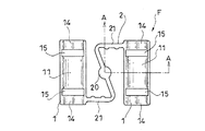
- FIG. 2 is a plan view of the vibration isolator.
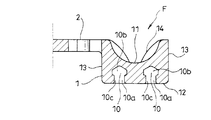
- 3 is a cross-sectional view taken along line AA in FIG.
- FIG. 4 is a side view of the vibration isolator.
- FIG. 5 is a bottom view of the vibration isolator.
- FIG. 6 is a plan view showing another configuration example of the vibration isolator.
- FIG. 7 is a plan view showing still another configuration example of the vibration isolator.
- FIG. 8 is a front view of the clamping device, and the clamping device is in an open state.
- FIG. 9 is a plan view of the clamping device.
- FIG. 10 is a front view showing a state in which the vibration isolator shown in FIG.
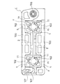
- FIG. 11 is a plan view of the clamping device of FIG.
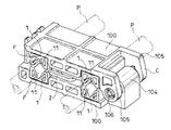
- FIG. 12 is a perspective view showing a state in which a long object is held by the clamping device of FIG.
- FIG. 13 is a front view of the clamping device in the state of FIG.
- the anti-vibration material F bundles long objects P such as piping and wiring, or a long object bundled on an object to be disposed (not shown).
- the clamp device C used for fixing a desired position of the object P is used.
- the vibration isolator F is used by being provided in a clamp device C that bundles pipes, tubes, harnes, and the like disposed in an automobile.
- vibration transmitted to the pipe or the like is absorbed by the vibration isolating material F, and abnormal noise (so-called chatter noise) due to such vibration can be prevented from being generated at the holding position by the clamp device C. .
- the anti-vibration material F is made of a rubber-like elastic material such as rubber or plastic elastomer. Further, the vibration isolator F includes a pair of clamp configurations in which a plurality of long objects P are spaced apart from each other, and the long objects P are substantially parallel to each other. It is used by being attached to the inner surface portion 101 of the clamp structure 100 in the clamping device C that is sandwiched and held between the inner surface portions 101 of the bodies 100 and 100.
- the clamping device C has an open position in which the other inner surface portion 101 and the other inner surface portion 101 are positioned on the same surface with respect to one of the pair of clamp structures 100, 100 ( 10 and 11) and a closed position (FIGS. 12 and 13) in which the inner surface 101 of both faces each other and the long object P can be sandwiched.
- each of the pair of clamp structures 100 and 100 is configured to have a substantially rectangular disk shape.
- Each of the inner surface portions 101 of the pair of clamp structures 100, 100 is provided with a groove-like portion 102 extending in the width direction at two locations at intervals in the length direction.
- Each groove-like portion 102 has a bottom surface portion 102a and left and right side surface portions 102b, 102b orthogonal to the bottom surface portion 102a. To open.
- two protrusions 103 On the bottom surface portion 102a of the groove-like portion 102, two protrusions 103 having a rib shape continuing along the groove length direction of the groove-like portion 102 are provided at intervals in the groove width direction.
- Each protrusion 103 has a substantially triangular head 103a at the top in the cross section perpendicular to the extending direction.
- a one-side bearing portion 104 is formed at one end of the pair of clamp structural bodies 100, 100 in the middle in the width direction. Further, two other-side bearing portions 105, 105 are formed at one end of the other of the pair of clamp structures 100, 100 with an interval for accommodating the one-side bearing portion 104 therebetween. Both bearing portions 104 and 105 are formed with shaft holes at positions above the inner surface portion 101 of the clamp structure 100.
- the pair of clamp structures 100 and 100 has the one-side bearing portion 104 at two locations.
- the shaft body 106 is inserted into the shaft hole in a state of being fitted between the other-side bearing portions 105, so that the rotation is combined.
- the other end portion of the clamp structure 100 and the other end portion of the clamp structure 100 are engaged with each other at the closed position, and the long object P is sandwiched and held by the pair of clamp structures 100 and 100.
- An engaging claw 107 that can maintain the state is formed.
- the anti-vibration material F has an attachment part 10 to the clamp structure 100, and the anti-vibration cell body 1 having the side facing the attachment part 10 as a contact part 11 for the side of one long object P. 2 or more in parallel.
- the contact portions 11 of the anti-vibration cell bodies 1 are arranged on the same side by connecting the adjacent anti-vibration cell bodies 1 and 1 to the connecting body 2 that can change the distance between the adjacent anti-vibration cell bodies 1 and 1. It is connected so that it may face.
- the vibration isolating material F is configured by connecting two anti-vibration cell bodies 1 and 1 with a connecting body 2.
- the antivibration cell body 1 is adapted to be fitted into the groove portion 102 of the clamp structure 100. That is, the antivibration cell body 1 has a width that fits in the groove-like portion 102 without a gap and a length that extends over the entire length of the groove-like portion 102, and is in close contact with the bottom surface portion 102 a of the groove-like portion 102. And a side surface portion 13 that is in close contact with the side surface portion 102 b of the groove-shaped portion 102.
- a valley-shaped part 14 is formed with the bottom in the middle of the vibration-proof cell body 1 in the width direction.
- the vibration isolating cell body 1 has a groove opening in the front portion thereof, and is provided with two lateral grooves 15 along the width direction at intervals in the length direction.
- the valley-shaped portion 14 is configured to have a semicircular cross section along the width direction of the antivibration cell body 1 at a location between the two lateral grooves 15, 15.
- the valley-shaped part 14 is comprised so that the cross section along the width direction of the anti-vibration cell body 1 may be made into a V shape in the location between the horizontal groove 15 and the edge part of the anti-vibration cell body 1.
- the mounting portion 10 is formed at a location between the two lateral grooves 15 in the vibration isolation cell body 1.
- the mounting portion 10 is a recess 10 a that receives the protrusion 103 formed in the clamp structure 100.
- two groove-shaped concave portions 10a are formed on the back surface portion 12 of the vibration-proof cell body 1, and the vibration-proof cell body 1 is fitted into the groove-shaped portion 102 as described above.
- the protrusion 103 corresponding to each of the two recesses 10a and 10a enters and is engaged.
- the recess 10a is configured such that the inner back portion 10b is wider than the entrance 10c side so that the head 103a of the projection 103 can be received, and the entrance 10c side is expanded in the process of fitting.
- the head 103a is deformed to receive the head 103a and to prevent the head 103a from coming out of the inner back portion 10b by elastic return at a position where the head 103a enters the inner back portion 10b. It is designed to engage.
- the vibration-proof cell body 1 has the valley portion 14 as a contact portion 11 with respect to the side portion of the long object P.
- the anti-vibration cell body 1 is attached to one inner surface portion 101 and the other inner surface portion 101 of the pair of clamp structure bodies 100, 100, respectively.
- a clamp device C is constituted by the two vibration isolating materials F and F. In each of the two clamp constituent bodies 100 and 100, one vibration-proof cell body 1 of the vibration-proof material F is fitted into one of the two groove-shaped parts 102 and 102, and the two groove-shaped parts 102 and 102 are formed.
- the other vibration-proof cell body 1 of the vibration-proof material F is fitted into the other, and the valley-like portion 14 of the vibration-proof material F attached to one of the pair of clamp components 100, 100 at the closed position is a pair of clamps. It faces the valley-shaped part 14 of the vibration isolator F attached to the other of the structural bodies 100,100. And in this closed position, two long objects P and P are left-right-spaced, respectively, and the trough-shaped part 14 of one vibration isolator F of a pair of clamp structure 100 and 100, and a pair The clamp structure 100 is sandwiched and held between the other vibration-proof material F of the clamp structure 100 and the valley-shaped portion 14. In the illustrated example, in this holding state, the V-shaped portion of the vibration-proof cell body 1 is deformed and crimped to the side portion of the long object P.
- the plurality of vibration isolation cell bodies 1 constituting the vibration isolation material F are gathered by the connecting body 2 so that the contact portions 11 face the same side, the plurality of vibration isolation cell bodies 1 are individually clamped components. As compared with the case of attaching to 100, the assembly of the vibration isolator F and the clamp structure 100 becomes easier.
- the vibration isolating cell body 1 is attached to the clamp structure 100 by the clamp device C, that is, between the type of the long object P held by the clamp device C and the long object P held by the clamp device C.
- the connecting body 2 connects the adjacent vibration-proof cell bodies 1 so that the distance between the adjacent vibration-proofing cell bodies 1 can be changed, so that the vibration-proofing material F has a different holding position for the long object P. It can be used by being attached to the clamp structure 100 of the plurality of clamp devices C to be made.
- the connecting body 2 includes a bar-shaped intermediate portion 20 positioned in the middle of the adjacent vibration-proof cell bodies 1 and 1, and one of the adjacent vibration-proof cell bodies 1 and 1 to the other.
- One arm portion 21 projecting toward one side and integrally connected to one end of the rod-shaped intermediate portion 20 and the other rod-shaped cell body 1, 1 projecting toward the other side from the other side, the rod shape.
- the other arm portion 21 is integrally connected to the other end of the intermediate portion 20.
- the connecting body 2 has a substantially S shape.
- the connecting body 2 is configured such that the angle inside the bent portion of the connecting portion between the rod-shaped intermediate portion 20 and the one arm portion 21 is increased, and the angle inside the bent portion at the connecting portion between the rod-shaped intermediate portion 20 and the other arm portion 21.
- the one arm portion 21 constituting the connecting body 2 is integrally connected to the upper portion of one side surface portion 13 of the adjacent vibration isolating cell body 1, 1, and the other arm portion 21 constituting the connecting body 2 is adjacent to the anti-vibration cell.
- the connecting body 2 is integrally connected to the upper portion of the other side surface portion 13 of the body 1, 1, and the connecting body 2 is on the inner surface portion 101 between the two groove-like portions 102, 102 in the pair of clamp constituent bodies 100, 100. Adjacent anti-vibration cell bodies 1 and 1 are connected.
- the connecting body 2 has one end integrally connected to one of the adjacent vibration-proof cell bodies 1, 1 and the other end integrated with the other of the adjacent vibration-proof cell bodies 1, 1. It is configured as a single bent or bent string-like body 22 connected to the.
- the connecting body 2 has a substantially U shape.
- the connecting body 2 is elastically deformed so as to increase the angle inside the curve, so that the distance between the adjacent anti-vibration cell bodies 1 and 1 can be maintained in a state where both the anti-vibration cell bodies 1 and 1 are in parallel. It can be spread as it is.
- the connecting body 2 has a rectangular frame shape, and one of the opposing corners 23 a, 23 a is integrally connected to one of the adjacent vibration-proof cell bodies 1, 1, and It is configured as a frame-like body 23 in which the other of the opposing corners 23a, 23a is integrally connected to the other of the adjacent vibration-proof cell bodies 1, 1.
- the connecting body 2 is elastically deformed so as to increase the angle of the bent inner side of the other two corners 23b, 23b not connected to the antivibration cell body 1 in the connecting body 2.
- the distance between the adjacent anti-vibration cell bodies 1 and 1 can be widened while keeping the anti-vibration cell bodies 1 and 1 in parallel.
Landscapes
- Engineering & Computer Science (AREA)
- General Engineering & Computer Science (AREA)
- Mechanical Engineering (AREA)
- Clamps And Clips (AREA)
- Vibration Prevention Devices (AREA)
- Supports For Pipes And Cables (AREA)
- Springs (AREA)
Abstract
複数の長尺物を、隣り合う長尺物間に間隔を開け、且つ、各長尺物が略平行をなすように、一対のクランプ構成体の内面部間に挟み込んで保持するクランプ装置における前記クランプ構成体の内面部に取り付け用いられるゴム又はゴム状弾性材よりなる防振材である。クランプ構成体への取り付け部を有すると共に、この取り付け部に対向する側を一つの長尺物の側部に対する接触部とした防振セル体を、二以上並列状態に有すると共に、隣り合う防振セル体を、この隣り合う防振セル体間の距離を可変可能とする連接体により、各防振セル体の接触部が同じ側に向くように連接させてなる。
Description
この発明は、複数の長尺物を束ねるために用いられるクランプ装置に組み合わされる防振材の改良に関する。
クランプ本体と、これにボルトによって固定される固定体と、アジャスト部材とからなるクランプ装置(配管クランプ)がある。かかるクランプ本体と固定体とにはそれぞれ保持凹部を有しており、両者を組み合わせた状態において組み合わされた保持凹部が円形の配管保持孔を構成するようになっている。クランプ本体の二箇所の保持凹部にはそれぞれ、弾性変形可能なアジャスト部材が着脱可能に取り付けられるようになっている。
この発明が解決しようとする主たる問題点は、複数の長尺物を同時に保持するクランプ装置に防振のために備えられる防振材を、このクランプ装置を構成するクランプ構成体の内面部に取り付けやすく、かつ、単一の防振材をもって構造の異なるクランプ装置にそれぞれ適切に取り付けることができるようにする点にある。
前記課題を解決するために、この発明にあっては、クランプ装置用防振材を、複数の長尺物を、隣り合う長尺物間に間隔を開け、且つ、各長尺物が略平行をなすように、一対のクランプ構成体の内面部間に挟み込んで保持するクランプ装置における前記クランプ構成体の内面部に取り付け用いられるゴム又はゴム状弾性材よりなる防振材であって、
クランプ構成体への取り付け部を有すると共に、この取り付け部に対向する側を一つの長尺物の側部に対する接触部とした防振セル体を、二以上並列状態に有すると共に、
隣り合う防振セル体を、この隣り合う防振セル体間の距離を可変可能とする連接体により、各防振セル体の接触部が同じ側に向くように連接させてなるものとした。
クランプ構成体への取り付け部を有すると共に、この取り付け部に対向する側を一つの長尺物の側部に対する接触部とした防振セル体を、二以上並列状態に有すると共に、
隣り合う防振セル体を、この隣り合う防振セル体間の距離を可変可能とする連接体により、各防振セル体の接触部が同じ側に向くように連接させてなるものとした。
防振体を構成する複数の防振セル体は前記連接体により接触部が同じ側に向くように纏められていることから、複数の防振セル体を個別にクランプ構成体に取り付ける場合に比べて防振体とクランプ構成体とのアセンブリーは容易となる。クランプ構成体に対する防振セル体の取り付け位置はクランプ装置によって、つまり、そのクランプ装置により保持される長尺物の種類やそのクランプ装置において保持される長尺物間に確保すべき間隔などによって異なることとなるが、前記連接体は隣り合う防振セル体の距離を可変可能に連接させることから、かかる防振体は長尺物の保持位置を異ならせる複数のクランプ装置のクランプ構成体に取り付け利用することができる。前記取り付け部は、クランプ構成体に形成された突部を受け入れる凹部としておくことが、好ましい態様の一つとされる。
連接体を、隣り合う防振セル体の中間に位置される棒状中間部と、隣り合う防振セル体の一方から他方の側に向けて突き出されて前記棒状中間部の一端に一体に連接される一方腕部と、隣り合う防振セル体の他方から一方の側に向けて突き出されて前記棒状中間部の他端に一体に連接される他方腕部とより構成させれば、連接体を、棒状中間部と一方腕部との間の屈曲内側の角度を大きくすると共に、棒状中間部と他方腕部との間の屈曲内側の角度を大きくするように弾性変形させることで、隣り合う防振セル体間の距離を両防振セル体の並列状態を保ったまま広げさせることができる。
また、連接体を、隣り合う防振セル体の一方に一端を一体に連接させ、且つ、隣り合う防振セル体の他方に他端を一体に連接させた一つの湾曲又は屈曲された紐状体として構成させれば、連接体をその湾曲又は屈曲内側の角度を大きくするように弾性変形させることで、隣り合う防振セル体間の距離を両防振セル体の並列状態を保ったまま広げさせることができる。
また、連接体は、四角形の枠状をなし、対向する隅部の一方を隣り合う防振セル体の一方に一体に連接させ、且つ、この対向する隅部の他方を隣り合う防振セル体の他方に一体に連接させた枠状体として構成させれば、連接体を、この連接体における防振セル体に連接されていないその余の二箇所の隅部の屈曲内側の角度を大きくするように弾性変形させることで、隣り合う防振セル体間の距離を両防振セル体の並列状態を保ったまま広げさせることができる。
この発明にかかる防振材は、クランプ装置を構成するクランプ構成体の内面部に取り付けやすく、かつ、単一の防振材をもって構造の異なるクランプ装置にそれぞれ適切に取り付けることができる。
以下、図1~図13に基づいて、この発明の典型的な実施の形態について、説明する。この実施の形態にかかる防振材Fは、配管、配線などの長尺物Pを、束ね、あるいは、この長尺物Pの配設対象物(図示は省略する。)に束ねられた長尺物Pの所望の位置を固定させるために用いられるクランプ装置Cに備えられて用いられるものである。
典型的には、かかる防振材Fは、自動車に配設されるパイプ、チューブ、ハーネースなどを束ねるクランプ装置Cに備えられて用いられる。この場合には、かかる防振材Fによって、前記パイプなどに伝わる振動は吸収され、クランプ装置Cによる保持箇所においてこうした振動に起因した異音(いわゆるビビリ音)が生じないようにすることができる。
かかる防振材Fは、ゴム、又は、プラスチックエラストマーなどのゴム状弾性材よりなる。また、かかる防振材Fは、複数の長尺物Pを、隣り合う長尺物P、P間に間隔を開け、且つ、各長尺物Pが略平行をなすように、一対のクランプ構成体100、100の内面部101間に挟み込んで保持するクランプ装置Cにおける前記クランプ構成体100の内面部101に取り付け用いられる。
図示の例では、かかるクランプ装置Cは、一対のクランプ構成体100、100の一方に対して他方を、一方の内面部101と他方の内面部101とを同面上に位置させた開き位置(図10、図11)と、両者の内面部101を向き合わせて長尺物Pを挟み込み可能とする閉じ位置(図12、図13)との間での回動可能に組み合わせてなる。
図示の例では、一対のクランプ構成体100、100はそれぞれ、略長方形の盤状をなすように構成されている。一対のクランプ構成体100、100の内面部101にはそれぞれ、その幅方向に亘る溝状部102が、その長さ方向に間隔を開けて、二箇所に設けられている。各溝状部102は、底面部102aと、この底面部102aに直交する左右側面部102b、102bとを有し、また、両溝端をクランプ構成体100の長さ方向に亘る側部において外方に開放させている。この溝状部102の底面部102aには、この溝状部102の溝長方向に沿って続くリブ状をなす突部103が、溝幅方向に間隔を開けて二条設けられている。各突部103はその延長方向に直交する向きの断面において、その上部を略三角形状をなす頭部103aとしている。一対のクランプ構成体100、100の一方の一端部であって、その幅方向中程の位置には、一方側軸受け部104が形成されている。また、一対のクランプ構成体100、100の他方の一端部には、二箇所の他方側軸受け部105、105が間に前記一方側軸受け部104を納める間隔を開けて形成されている。両軸受け部104、105にはクランプ構成体100の内面部101よりも上方となる位置に軸孔が形成されており、一対のクランプ構成体100、100は、前記一方側軸受け部104を二箇所の他方側軸受け部105の間に納めた状態で前記軸孔に軸体106を挿通することで、前記回動可能に組み合わされている。また、クランプ構成体100の一方の他端部と他方の他端部とにはそれぞれ、前記閉じ位置において係合し合って、一対のクランプ構成体100、100により長尺物Pを挟み込み保持した状態を維持可能とする係合爪107が形成されている。
防振材Fは、前記クランプ構成体100への取り付け部10を有すると共に、この取り付け部10に対向する側を一つの長尺物Pの側部に対する接触部11とした防振セル体1を、二以上並列状態に有する。それと共に、隣り合う防振セル体1、1を、この隣り合う防振セル体1、1間の距離を可変可能とする連接体2により、各防振セル体1の接触部11が同じ側に向くように連接させてなる。図示の例では、防振材Fは、二つの防振セル体1、1を連接体2により連接させて構成されている。
防振セル体1は、前記クランプ構成体100の溝状部102に嵌め込まれるようになっている。すなわち、防振セル体1は、かかる溝状部102に隙間無く納まる幅と、この溝状部102の全長に亘る長さとを備え、溝状部102の底面部102aに密着される背面部12と溝状部102の側面部102bに密着される側面部13とを有している。
防振セル体1の正面部には、防振セル体1の幅方向略中程の位置を底とする谷状部14が形成されている。図示の例では、防振セル体1には、その正面部に溝口を開放させ、その幅方向に沿った横溝15が、その長さ方向において間隔を開けて二箇所に設けられている。谷状部14は、この二箇所の横溝15、15の間となる箇所では、防振セル体1の幅方向に沿った断面を半円状とするように構成されている。また、谷状部14は、横溝15と防振セル体1の端部との間となる箇所では、防振セル体1の幅方向に沿った断面をV字状とするように構成されている。このV字状箇所においては、谷状部14の底を挟んだ両側にそれぞれ、防振セル体1の端部から横溝15に続く貫通孔16が形成されており、この貫通孔16によってV字状箇所においては谷状部14の底を挟んだ両側は弾性変形し易くなっている。
前記取り付け部10は、防振セル体1における二箇所の横溝15の間となる箇所に形成されている。この実施の形態にあっては、かかる取り付け部10は、クランプ構成体100に形成された前記突部103を受け入れる凹部10aとなっている。図示の例では、防振セル体1の背面部12に、二箇所の溝状をなす凹部10aが形成されており、前記溝状部102に防振セル体1を前記のように嵌め込んだときに、二箇所の凹部10a、10aのそれぞれに対応する前記突部103が入り込み係合されるようになっている。図示の例では、凹部10aはその入り口10c側よりも内奥部10bを前記突部103の頭部103aを受け入れ可能に広く構成させており、前記はめ込みの過程で入り口10c側を広げるように弾性変形して前記頭部103aを受け入れ、かつ、この頭部103aが内奥部10bに入り込んだ位置での弾性復帰によりこの内奥部10bからかかる頭部103aを抜け出させないようにこの頭部103aに係合するようになっている。
かかる防振セル体1は、前記谷状部14を長尺物Pの側部に対する接触部11とする。図示の例では、一対のクランプ構成体100、100の一方の内面部101と、他方の内面部101とにそれぞれ、防振セル体1が取り付けられて、二つのクランプ構成体100、100と二つの防振材F、Fとによりクランプ装置Cが構成されるようになっている。二つのクランプ構成体100、100のそれぞれにおいて、二箇所の溝状部102、102の一方に防振材Fの一方の防振セル体1が嵌め込まれ、二箇所の溝状部102、102の他方に防振材Fの他方の防振セル体1が嵌め込まれると共に、前記閉じ位置において一対のクランプ構成体100、100の一方に取り付けられた防振材Fの谷状部14が一対のクランプ構成体100、100の他方に取り付けられた防振材Fの谷状部14に向き合うようになっている。そして、この閉じ位置において、二本の長尺物P、Pを、左右に間隔を開けて、それぞれ、一対のクランプ構成体100、100の一方の防振材Fの谷状部14と一対のクランプ構成体100、100の他方の防振材Fの谷状部14との間で挟み込み保持するようになっている。図示の例では、この保持状態において、防振セル体1の前記V字状箇所は変形して長尺物Pの側部に圧着されるようになっている。
防振材Fを構成する複数の防振セル体1は前記連接体2により接触部11が同じ側に向くように纏められていることから、複数の防振セル体1を個別にクランプ構成体100に取り付ける場合に比べて防振材Fとクランプ構成体100とのアセンブリーは容易となる。クランプ構成体100に対する防振セル体1の取り付け位置はクランプ装置Cによって、つまり、そのクランプ装置Cにより保持される長尺物Pの種類やそのクランプ装置Cにおいて保持される長尺物P間に確保すべき間隔などによって異なることとなるが、前記連接体2は隣り合う防振セル体1の距離を可変可能に連接させることから、かかる防振材Fは長尺物Pの保持位置を異ならせる複数のクランプ装置Cのクランプ構成体100に取り付け利用することができる。
図1~図5に示される例では、連接体2は、隣り合う防振セル体1、1の中間に位置される棒状中間部20と、隣り合う防振セル体1、1の一方から他方の側に向けて突き出されて前記棒状中間部20の一端に一体に連接される一方腕部21と、隣り合う防振セル体1、1の他方から一方の側に向けて突き出されて前記棒状中間部20の他端に一体に連接される他方腕部21とより構成されている。この例では、連接体2は略S字状を呈している。この例では、連接体2を、棒状中間部20と一方腕部21との連接箇所の屈曲内側の角度を大きくすると共に、棒状中間部20と他方腕部21との連接箇所の屈曲内側の角度を大きくするように弾性変形させることで、隣り合う防振セル体1、1間の距離を両防振セル体1、1の並列状態を保ったまま広げさせることができる。連接体2を構成する一方腕部21は隣り合う防振セル体1、1の一方の側面部13の上部に一体に連接され、連接体2を構成する他方腕部21は隣り合う防振セル体1、1の他方の側面部13の上部に一体に連接され、連接体2は一対のクランプ構成体100、100における二箇所の溝状部102、102間にある内面部101上にあって隣り合う防振セル体1、1を連接する。
図6に示される例では、連接体2は、隣り合う防振セル体1、1の一方に一端を一体に連接させ、且つ、隣り合う防振セル体1、1の他方に他端を一体に連接させた一つの湾曲又は屈曲された紐状体22として構成されている。この例では、連接体2は略U字状を呈している。この例では、連接体2をその湾曲内側の角度を大きくするように弾性変形させることで、隣り合う防振セル体1、1間の距離を両防振セル体1、1の並列状態を保ったまま広げさせることができる。
図7に示される例では、連接体2は、四角形の枠状をなし、対向する隅部23a、23aの一方を隣り合う防振セル体1、1の一方に一体に連接させ、且つ、この対向する隅部23a、23aの他方を隣り合う防振セル体1、1の他方に一体に連接させた枠状体23として構成されている。この例では、連接体2を、この連接体2における防振セル体1に連接されていないその余の二箇所の隅部23b、23bの屈曲内側の角度を大きくするように弾性変形させることで、隣り合う防振セル体1、1間の距離を両防振セル体1、1の並列状態を保ったまま広げさせることができる。
2011年4月26日に出願された日本特許出願第2011-098504号の明細書、特許請求の範囲、図面及び要約書の全内容をここに引用し、本発明の明細書の開示として、取り入れるものである。
2011年4月26日に出願された日本特許出願第2011-098504号の明細書、特許請求の範囲、図面及び要約書の全内容をここに引用し、本発明の明細書の開示として、取り入れるものである。
Claims (5)
- 複数の長尺物を、隣り合う長尺物間に間隔を開け、且つ、各長尺物が略平行をなすように、一対のクランプ構成体の内面部間に挟み込んで保持するクランプ装置における前記クランプ構成体の内面部に取り付け用いられるゴム又はゴム状弾性材よりなる防振材であって、
クランプ構成体への取り付け部を有すると共に、この取り付け部に対向する側を一つの長尺物の側部に対する接触部とした防振セル体を、二以上並列状態に有すると共に、
隣り合う防振セル体を、この隣り合う防振セル体間の距離を可変可能とする連接体により、各防振セル体の接触部が同じ側に向くように連接させてなることを特徴とするクランプ装置用防振材。 - 取り付け部は、クランプ構成体に形成された突部を受け入れる凹部であることを特徴とする請求項1に記載のクランプ装置用防振材。
- 連接体は、隣り合う防振セル体の中間に位置される棒状中間部と、隣り合う防振セル体の一方から他方の側に向けて突き出されて前記棒状中間部の一端に一体に連接される一方腕部と、隣り合う防振セル体の他方から一方の側に向けて突き出されて前記棒状中間部の他端に一体に連接される他方腕部とより構成されていることを特徴とする請求項1又は請求項2に記載のクランプ装置用防振材。
- 連接体は、隣り合う防振セル体の一方に一端を一体に連接させ、且つ、隣り合う防振セル体の他方に他端を一体に連接させた一つの湾曲又は屈曲された紐状体であることを特徴とする請求項1又は請求項2に記載のクランプ装置用防振材。
- 連接体は、四角形の枠状をなし、対向する隅部の一方を隣り合う防振セル体の一方に一体に連接させ、且つ、この対向する隅部の他方を隣り合う防振セル体の他方に一体に連接させた枠状体であることを特徴とする請求項1又は請求項2に記載のクランプ装置用防振材。
Applications Claiming Priority (2)
| Application Number | Priority Date | Filing Date | Title |
|---|---|---|---|
| JP2011098504A JP5684036B2 (ja) | 2011-04-26 | 2011-04-26 | クランプ装置用防振材 |
| JP2011-098504 | 2011-04-26 |
Publications (1)
| Publication Number | Publication Date |
|---|---|
| WO2012147591A1 true WO2012147591A1 (ja) | 2012-11-01 |
Family
ID=47072112
Family Applications (1)
| Application Number | Title | Priority Date | Filing Date |
|---|---|---|---|
| PCT/JP2012/060492 Ceased WO2012147591A1 (ja) | 2011-04-26 | 2012-04-18 | クランプ装置用防振材 |
Country Status (2)
| Country | Link |
|---|---|
| JP (1) | JP5684036B2 (ja) |
| WO (1) | WO2012147591A1 (ja) |
Cited By (1)
| Publication number | Priority date | Publication date | Assignee | Title |
|---|---|---|---|---|
| EP3988768A1 (en) * | 2020-10-13 | 2022-04-27 | Illinois Tool Works Inc. | Mounting member |
Citations (7)
| Publication number | Priority date | Publication date | Assignee | Title |
|---|---|---|---|---|
| JPS5112618Y2 (ja) * | 1971-05-25 | 1976-04-05 | ||
| JPH02205648A (ja) * | 1988-10-03 | 1990-08-15 | Sony Corp | バネ材 |
| JPH0741177U (ja) * | 1993-12-22 | 1995-07-21 | 株式会社ニフコ | 配管クランプ |
| JPH09144794A (ja) * | 1995-11-20 | 1997-06-03 | Nishikawa Sangyo Kk | スプリング |
| JP2000213581A (ja) * | 1999-01-22 | 2000-08-02 | Musashino Kiko Kk | プラスチック製の筒状バネ |
| JP2004100821A (ja) * | 2002-09-10 | 2004-04-02 | Hitachi Plant Eng & Constr Co Ltd | 配管用サポート |
| JP2006177462A (ja) * | 2004-12-22 | 2006-07-06 | Mitsubishi Motors Corp | チューブクリップ |
-
2011
- 2011-04-26 JP JP2011098504A patent/JP5684036B2/ja not_active Expired - Fee Related
-
2012
- 2012-04-18 WO PCT/JP2012/060492 patent/WO2012147591A1/ja not_active Ceased
Patent Citations (7)
| Publication number | Priority date | Publication date | Assignee | Title |
|---|---|---|---|---|
| JPS5112618Y2 (ja) * | 1971-05-25 | 1976-04-05 | ||
| JPH02205648A (ja) * | 1988-10-03 | 1990-08-15 | Sony Corp | バネ材 |
| JPH0741177U (ja) * | 1993-12-22 | 1995-07-21 | 株式会社ニフコ | 配管クランプ |
| JPH09144794A (ja) * | 1995-11-20 | 1997-06-03 | Nishikawa Sangyo Kk | スプリング |
| JP2000213581A (ja) * | 1999-01-22 | 2000-08-02 | Musashino Kiko Kk | プラスチック製の筒状バネ |
| JP2004100821A (ja) * | 2002-09-10 | 2004-04-02 | Hitachi Plant Eng & Constr Co Ltd | 配管用サポート |
| JP2006177462A (ja) * | 2004-12-22 | 2006-07-06 | Mitsubishi Motors Corp | チューブクリップ |
Cited By (1)
| Publication number | Priority date | Publication date | Assignee | Title |
|---|---|---|---|---|
| EP3988768A1 (en) * | 2020-10-13 | 2022-04-27 | Illinois Tool Works Inc. | Mounting member |
Also Published As
| Publication number | Publication date |
|---|---|
| JP5684036B2 (ja) | 2015-03-11 |
| JP2012229754A (ja) | 2012-11-22 |
Similar Documents
| Publication | Publication Date | Title |
|---|---|---|
| JP5939237B2 (ja) | 作業機械の索状体保持具 | |
| CN102918283B (zh) | 车辆隔振附接组件 | |
| EP0666628B1 (en) | Anti-resonance pipe clip | |
| JP6401153B2 (ja) | 回転を制限する管留め具 | |
| CN103249980A (zh) | 夹具 | |
| JP2005155749A (ja) | パイプクランプ | |
| KR20090057905A (ko) | 복합 관 클립 | |
| JP6399383B2 (ja) | 防振クランプ | |
| KR20130033307A (ko) | 케이블용 보호 가이드 및 보호 가이드에 이용되는 브라켓 | |
| US20150152953A1 (en) | Powertrain roll restrictor | |
| CN105397843A (zh) | 线条体固定装置 | |
| KR20140131646A (ko) | 역조립 방지 케이블 고정용 클립 | |
| JP5684036B2 (ja) | クランプ装置用防振材 | |
| JP5102507B2 (ja) | 防振クランプ装置 | |
| JP6649543B2 (ja) | 配管支持具 | |
| WO2011007814A1 (ja) | クリップ | |
| US10277020B2 (en) | Leadthrough device and building with a leadthrough device | |
| JP6649544B2 (ja) | 配管支持具 | |
| WO2016080047A1 (ja) | 防振装置用ブラケットおよび防振装置 | |
| JP6547590B2 (ja) | 連結構造 | |
| US10274037B2 (en) | Vibration-damping device and attachment structure for vibration-damping device | |
| JP7341401B2 (ja) | 樹脂製締付部材 | |
| JP2019128004A (ja) | 配管支持具 | |
| JP2019043276A5 (ja) | ||
| ES2671736T3 (es) | Clip de soporte y conjunto de tubos |
Legal Events
| Date | Code | Title | Description |
|---|---|---|---|
| 121 | Ep: the epo has been informed by wipo that ep was designated in this application |
Ref document number: 12776522 Country of ref document: EP Kind code of ref document: A1 |
|
| NENP | Non-entry into the national phase |
Ref country code: DE |
|
| 122 | Ep: pct application non-entry in european phase |
Ref document number: 12776522 Country of ref document: EP Kind code of ref document: A1 |