WO2012147529A1 - Foamed resin molded article - Google Patents
Foamed resin molded article Download PDFInfo
- Publication number
- WO2012147529A1 WO2012147529A1 PCT/JP2012/060016 JP2012060016W WO2012147529A1 WO 2012147529 A1 WO2012147529 A1 WO 2012147529A1 JP 2012060016 W JP2012060016 W JP 2012060016W WO 2012147529 A1 WO2012147529 A1 WO 2012147529A1
- Authority
- WO
- WIPO (PCT)
- Prior art keywords
- nucleating agent
- foamed resin
- resin molded
- molding
- foamed
- Prior art date
Links
Images


Classifications
-
- B—PERFORMING OPERATIONS; TRANSPORTING
- B29—WORKING OF PLASTICS; WORKING OF SUBSTANCES IN A PLASTIC STATE IN GENERAL
- B29C—SHAPING OR JOINING OF PLASTICS; SHAPING OF MATERIAL IN A PLASTIC STATE, NOT OTHERWISE PROVIDED FOR; AFTER-TREATMENT OF THE SHAPED PRODUCTS, e.g. REPAIRING
- B29C45/00—Injection moulding, i.e. forcing the required volume of moulding material through a nozzle into a closed mould; Apparatus therefor
- B29C45/0001—Injection moulding, i.e. forcing the required volume of moulding material through a nozzle into a closed mould; Apparatus therefor characterised by the choice of material
-
- B—PERFORMING OPERATIONS; TRANSPORTING
- B29—WORKING OF PLASTICS; WORKING OF SUBSTANCES IN A PLASTIC STATE IN GENERAL
- B29C—SHAPING OR JOINING OF PLASTICS; SHAPING OF MATERIAL IN A PLASTIC STATE, NOT OTHERWISE PROVIDED FOR; AFTER-TREATMENT OF THE SHAPED PRODUCTS, e.g. REPAIRING
- B29C44/00—Shaping by internal pressure generated in the material, e.g. swelling or foaming ; Producing porous or cellular expanded plastics articles
- B29C44/02—Shaping by internal pressure generated in the material, e.g. swelling or foaming ; Producing porous or cellular expanded plastics articles for articles of definite length, i.e. discrete articles
- B29C44/04—Shaping by internal pressure generated in the material, e.g. swelling or foaming ; Producing porous or cellular expanded plastics articles for articles of definite length, i.e. discrete articles consisting of at least two parts of chemically or physically different materials, e.g. having different densities
-
- B—PERFORMING OPERATIONS; TRANSPORTING
- B29—WORKING OF PLASTICS; WORKING OF SUBSTANCES IN A PLASTIC STATE IN GENERAL
- B29C—SHAPING OR JOINING OF PLASTICS; SHAPING OF MATERIAL IN A PLASTIC STATE, NOT OTHERWISE PROVIDED FOR; AFTER-TREATMENT OF THE SHAPED PRODUCTS, e.g. REPAIRING
- B29C44/00—Shaping by internal pressure generated in the material, e.g. swelling or foaming ; Producing porous or cellular expanded plastics articles
- B29C44/34—Auxiliary operations
- B29C44/3469—Cell or pore nucleation
-
- B—PERFORMING OPERATIONS; TRANSPORTING
- B32—LAYERED PRODUCTS
- B32B—LAYERED PRODUCTS, i.e. PRODUCTS BUILT-UP OF STRATA OF FLAT OR NON-FLAT, e.g. CELLULAR OR HONEYCOMB, FORM
- B32B5/00—Layered products characterised by the non- homogeneity or physical structure, i.e. comprising a fibrous, filamentary, particulate or foam layer; Layered products characterised by having a layer differing constitutionally or physically in different parts
- B32B5/18—Layered products characterised by the non- homogeneity or physical structure, i.e. comprising a fibrous, filamentary, particulate or foam layer; Layered products characterised by having a layer differing constitutionally or physically in different parts characterised by features of a layer of foamed material
- B32B5/20—Layered products characterised by the non- homogeneity or physical structure, i.e. comprising a fibrous, filamentary, particulate or foam layer; Layered products characterised by having a layer differing constitutionally or physically in different parts characterised by features of a layer of foamed material foamed in situ
-
- C—CHEMISTRY; METALLURGY
- C08—ORGANIC MACROMOLECULAR COMPOUNDS; THEIR PREPARATION OR CHEMICAL WORKING-UP; COMPOSITIONS BASED THEREON
- C08J—WORKING-UP; GENERAL PROCESSES OF COMPOUNDING; AFTER-TREATMENT NOT COVERED BY SUBCLASSES C08B, C08C, C08F, C08G or C08H
- C08J9/00—Working-up of macromolecular substances to porous or cellular articles or materials; After-treatment thereof
- C08J9/0066—Use of inorganic compounding ingredients
-
- C—CHEMISTRY; METALLURGY
- C08—ORGANIC MACROMOLECULAR COMPOUNDS; THEIR PREPARATION OR CHEMICAL WORKING-UP; COMPOSITIONS BASED THEREON
- C08J—WORKING-UP; GENERAL PROCESSES OF COMPOUNDING; AFTER-TREATMENT NOT COVERED BY SUBCLASSES C08B, C08C, C08F, C08G or C08H
- C08J9/00—Working-up of macromolecular substances to porous or cellular articles or materials; After-treatment thereof
- C08J9/04—Working-up of macromolecular substances to porous or cellular articles or materials; After-treatment thereof using blowing gases generated by a previously added blowing agent
- C08J9/06—Working-up of macromolecular substances to porous or cellular articles or materials; After-treatment thereof using blowing gases generated by a previously added blowing agent by a chemical blowing agent
- C08J9/08—Working-up of macromolecular substances to porous or cellular articles or materials; After-treatment thereof using blowing gases generated by a previously added blowing agent by a chemical blowing agent developing carbon dioxide
-
- C—CHEMISTRY; METALLURGY
- C08—ORGANIC MACROMOLECULAR COMPOUNDS; THEIR PREPARATION OR CHEMICAL WORKING-UP; COMPOSITIONS BASED THEREON
- C08J—WORKING-UP; GENERAL PROCESSES OF COMPOUNDING; AFTER-TREATMENT NOT COVERED BY SUBCLASSES C08B, C08C, C08F, C08G or C08H
- C08J9/00—Working-up of macromolecular substances to porous or cellular articles or materials; After-treatment thereof
- C08J9/34—Chemical features in the manufacture of articles consisting of a foamed macromolecular core and a macromolecular surface layer having a higher density than the core
-
- C—CHEMISTRY; METALLURGY
- C08—ORGANIC MACROMOLECULAR COMPOUNDS; THEIR PREPARATION OR CHEMICAL WORKING-UP; COMPOSITIONS BASED THEREON
- C08J—WORKING-UP; GENERAL PROCESSES OF COMPOUNDING; AFTER-TREATMENT NOT COVERED BY SUBCLASSES C08B, C08C, C08F, C08G or C08H
- C08J2205/00—Foams characterised by their properties
- C08J2205/04—Foams characterised by their properties characterised by the foam pores
- C08J2205/048—Bimodal pore distribution, e.g. micropores and nanopores coexisting in the same foam
-
- Y—GENERAL TAGGING OF NEW TECHNOLOGICAL DEVELOPMENTS; GENERAL TAGGING OF CROSS-SECTIONAL TECHNOLOGIES SPANNING OVER SEVERAL SECTIONS OF THE IPC; TECHNICAL SUBJECTS COVERED BY FORMER USPC CROSS-REFERENCE ART COLLECTIONS [XRACs] AND DIGESTS
- Y10—TECHNICAL SUBJECTS COVERED BY FORMER USPC
- Y10T—TECHNICAL SUBJECTS COVERED BY FORMER US CLASSIFICATION
- Y10T428/00—Stock material or miscellaneous articles
- Y10T428/249921—Web or sheet containing structurally defined element or component
- Y10T428/249953—Composite having voids in a component [e.g., porous, cellular, etc.]
- Y10T428/249987—With nonvoid component of specified composition
- Y10T428/249988—Of about the same composition as, and adjacent to, the void-containing component
- Y10T428/249989—Integrally formed skin
Definitions
- the present invention relates to a foamed resin molded body molded by an injection foam molding method or the like.
- the foamed resin molded body has a higher proportion of bubbles (foamed cells), that is, the higher the foaming ratio, the lighter the weight, and the smaller the diameter of the foamed resin molded body, the better the physical properties such as impact resistance. Therefore, it is preferable that the foam cells formed in the foamed resin molded body have a small diameter and a large number.
- the molding method of the foamed resin molding is roughly divided into two types, physical foaming and chemical foaming.
- Physical foaming is a method in which air, carbon dioxide, nitrogen, or a volatile solvent pressurized in a cylinder of an injection molding machine is dissolved in a resin.
- Chemical foaming is a method in which a chemical foaming agent is introduced together with a base material from a hopper port of an injection molding machine, and gases such as carbon dioxide, nitrogen, water, and ammonia are mixed into the resin by thermal decomposition or chemical reaction.
- the pressure and temperature can be easily adjusted, so carbon dioxide and nitrogen in a supercritical state can be directly injected into the resin.
- supercritical fluid has compressibility like liquid and diffusibility like gas, it can impart high diffusivity and high solubility to carbon dioxide and nitrogen.
- the foamed cells formed in the foamed resin molded body have a small diameter and a large number of foamed molded bodies.
- a nucleating agent is added to a resin for the purpose of reducing the pore diameter of foamed cells in the foamed resin molded body and increasing the number of foamed cells. This is based on the feature that bubbles are generated starting from the surface of the object, and the generation point of bubbles can be increased by the nucleating agent. Therefore, the nucleating agent is particularly effective in chemical foaming. .
- an organic substance such as a citric acid type has been conventionally used.
- these organic substances are decomposed by heat, and a tar-like substance is generated.
- a certain high temperature is required.
- the above nucleating agent composed of organic substances decomposes or deteriorates. In some cases, the temperature may be higher. In this case, the decomposed or deteriorated nucleating agent may impair the appearance of the surface of the foamed resin molded body, roughen the foamed cells, or cause odor. Will drop significantly.
- nucleating agent in order to make the nucleating agent resistant to heat, not an organic substance but an inorganic substance or a combination of an organic substance and an inorganic substance is used as a nucleating agent.
- Patent Document 1 showing an example of chemical foaming includes a melted resin, a foaming agent, and calcium carbonate, talc, mica, or the like as a nucleating agent having a particle size of 2 to 50 ⁇ m, particularly preferably 5 to 20 ⁇ m. It is shown that the inorganic compound powder is mixed.
- an inorganic talc having a particle size of about 1 to 100 ⁇ m is used as a nucleating agent.
- this nucleating agent has an effect of increasing the number of bubbles, the number of bubbles is not sufficient to form a cell structure having a large number of fine foam cells in the molded foamed resin molded article.
- This invention is made
- the foamed resin molded body of the present invention has a surface formed of a skin layer and an interior formed of a foam layer.
- a plurality of first foam cells and a plurality of second foam cells formed between the first foam cells and smaller than the first foam cells are formed.
- a large number of fine foam cells can be formed in the foam layer of the foamed resin molded body, and the impact resistance and rigidity of the foamed resin molded body can be improved.
- the foamed resin molded body molded by the present invention is obtained by mixing a foaming agent with a thermoplastic resin as a base resin, and further, as a nucleating agent, on the surface of the first nucleating agent from the first nucleating agent. Is obtained by injection foaming a mixture of a composite formed by adhering a second nucleating agent having a small average particle size.
- base material resin As the base material resin used in the present invention, polyolefin resins such as polypropylene and polyethylene are preferably used, but are not limited thereto.
- polystyrene resins such as polystyrene, ABS (acrylonitrile, butadiene, styrene copolymer synthesis) resin, AS (acrylonitrile, styrene copolymer synthesis) resin; polyamide resins such as nylon 6, nylon 66, nylon 12; polyethylene terephthalate ( PET), polybutylene terephthalate (PBT), polytrimethylene terephthalate (PTT), polyethylene naphthalate (PEN), polyester resins such as polylactic acid; polyvinyl chloride; polycarbonate (PC); polyacetal (POM); polyimide; Ether ether ketone (PEEK), etc. can be used. These matrix resins may be modified. Two or more kinds of resins may be used in combination.
- Foaming agent As the foaming agent used in the present invention, a thermal decomposition type or reactive type foaming agent using a chemical foaming agent is used. Specifically, azo compounds such as azodicarbonamide, nitroso compounds such as N, N-dinitrosopentamethylenetetramine, hydrazine derivatives such as 4,4′-oxybis (benzenesulfonylhydrazide), hydrazodicarbonamide, hydrogen carbonate A bicarbonate such as sodium, a carbonate such as sodium carbonate or ammonium carbonate, a nitrite such as ammonium nitrite, a semicarbazide compound, an azide compound, a tetrazole compound, an isocyanate compound, or a hydroxide is preferably used.
- azo compounds such as azodicarbonamide, nitroso compounds such as N, N-dinitrosopentamethylenetetramine, hydrazine derivatives such as 4,4′-oxybis (benzen
- Foaming aids such as urea, organic nucleating agents such as sodium citrate, talc, or calcium carbonate or inorganic nucleating agents may be added in combination. These foaming agents may be used in combination of two or more kinds of foaming agents.
- a master batch of sodium hydrogen carbonate and sodium citrate, a nucleating agent is preferably used.
- the nucleating agent of the present invention comprises a complex of the first nucleating agent and the second nucleating agent having an average particle size smaller than that of the first nucleating agent.
- the 1st nucleating agent and the 2nd nucleating agent mentioned later have a function used as the starting point from which the bubble used as the foaming cell of a foaming resin molding is generated.
- silicates such as talc, mica, silica, clay, montmorillonite and kaolin; carbonates such as calcium carbonate, lithium carbonate and magnesium carbonate; metal oxides such as alumina, titanium oxide and zinc oxide Metals such as aluminum, iron, silver and copper; hydroxides such as aluminum hydroxide and magnesium hydroxide; sulfides such as barium sulfate; carbides such as charcoal and bamboo charcoal; titanium such as potassium titanate and barium titanate And the like.
- talc is particularly preferable.
- the particle size of the first nucleating agent using the inorganic material is preferably 0.5 to 1000 ⁇ m, more preferably 1 to 10 ⁇ m. If the particle size is 0.5 ⁇ m or more, the fine particles of the first nucleating agent can be easily produced. Furthermore, by attaching a large number of nano-sized (less than 1 ⁇ m) second nucleating agents to the surface of the first nucleating agent, the first nucleating agent is incorporated into the base resin. It becomes possible to function as a carrier for dispersing the agent. Moreover, if a particle size is 1000 micrometers or less, in the foamed resin molding after shaping
- plant fiber such as plant fiber, cellulose fiber, cellulose acetate fiber, polyethylene terephthalate fiber, nylon fiber, polyethylene naphthalate fiber, aramid fiber, vinylon fiber, or polyarylate
- Fiber powders such as fibers can be used.
- the fiber powder may be a core-sheath type or side-by-side type composite fiber in order to improve dispersibility and adhesion to the base resin.
- a hollow fiber may be used for weight reduction and heat resistance improvement.
- These fiber powders are desirably fine fibers having an average fiber diameter of 0.5 to 250 ⁇ m and an average fiber length of 1 to 3000 ⁇ m. Further, the average fiber diameter is preferably 1 to 100 ⁇ m and the average fiber length is preferably 10 to 500 ⁇ m, more preferably the average fiber diameter is 1 to 40 ⁇ m and the average fiber length is 20 to 300 ⁇ m.
- Examples of the second nucleating agent include silicates such as talc, silica, clay, montmorillonite, and kaolin; carbonates such as calcium carbonate, lithium carbonate, and magnesium carbonate; metal oxides such as alumina, titanium oxide, and zinc oxide.
- Metals such as aluminum, iron, silver and copper; hydroxides such as aluminum hydroxide and magnesium hydroxide; sulfides such as barium sulfate; carbides such as charcoal and bamboo charcoal; titanium such as potassium titanate and barium titanate And the like; celluloses such as cellulose microfibrils and cellulose acetate; carbons such as fullerenes and carbon nanotubes.
- calcium carbonate mica, montmorillonite, and titanium oxide are preferable.
- calcium carbonate is preferred because nanosized particles can be produced or obtained relatively easily and inexpensively.
- the shape of the second nucleating agent may be any shape such as a spherical shape, a plate shape, a fiber shape, and a hollow shape. Moreover, fine particles having a specific shape may be used alone, or two or more kinds of fine particles having different shapes may be used in combination.
- the second nucleating agent of the present invention includes not only primary particles but also secondary or higher particles as long as they fall within the size (particle size) range of the second nucleating agent described later. It is.
- the size of the second nucleating agent needs to be nano-sized with an average particle size of less than 1 ⁇ m. Specifically, the average particle diameter is 10 to 500 nm. When the average particle size is 10 nm or more, it is advantageous in terms of enhancing the dispersibility of the second nucleating agent, and when the average particle size is 500 nm or less, the specific surface area is increased to increase the starting point where bubbles are generated. This is advantageous in terms of miniaturization.
- the size of the second nucleating agent is more preferably 20 to 200 nm, and particularly preferably 50 to 100 nm.
- first nucleating agent and second nucleating agent are mixed with the base material resin in a complex formed by adhering the second nucleating agent to the surface of the first nucleating agent. Is done.
- the first nucleating agent and the second nucleating agent are previously pulverized to the above-mentioned sizes or adjusted by the precipitation method. Then, the composite is obtained by stirring the first nucleating agent, the second nucleating agent, and stearic acid together with a Henschel mixer for surface treatment described later at a high speed.
- the stirring conditions are preferably dry and the peripheral speed of the rotary blade is 20 m / s or more.
- the nano-sized second nucleating agent is attached so as to cover the surface of the first nucleating agent to form a complex.
- the above-mentioned base material resin and the above-mentioned composite are biaxially formed at a ratio of 1 to 80% by mass (more preferably 3 to 50% by mass, particularly preferably 5 to 20% by mass) of the composite based on the weight of the base resin. Put into a kneading extruder and knead and mix. At this time, since the composite is separated and dispersed into the first nucleating agent and the second nucleating agent in the base material resin, the second nucleating agents come to exist independently.
- the second nucleating agent is surface-treated with stearic acid so that the second nucleating agent becomes hydrophobic, the affinity between the second nucleating agent and the base resin is high. It becomes high and it becomes difficult to re-aggregate.
- a master batch in which the composite is blended with the resin at a high concentration may be produced, and this master batch may be further blended with the resin.
- a base material resin mixed with the composite and a foaming agent, and if necessary, a masterbatch containing a pigment corresponding to a desired color variation of the foamed resin molding is dry blended.
- the dry blended mixture is supplied to an injection molding machine, and is injected into a space formed by two molds, that is, cavities in a state where foaming of the foaming agent is suppressed under a certain pressure condition. Then, after the skin layer is formed, one mold is retracted with respect to the other mold, thereby reducing the density of the mixture and releasing the pressure. This is the so-called cavity expansion method. Thereby, the foaming agent is decomposed, and bubbles such as carbon dioxide gas and nitrogen gas are generated starting from the surfaces of the first nucleating agent and the second nucleating agent. This bubble becomes a foam cell, a foam layer is formed, and a foamed resin molded product is molded.
- a short shot method, an egress method, or the like may be used as a method for molding the foamed resin molded body.
- the first nucleating agent and the second nucleating agent are uniformly dispersed in the base material resin. Therefore, in the foamed resin molded body according to the present invention, the first foamed cell due to the bubbles generated on the surface of the first nucleating agent and the second foamed cell due to the bubbles generated on the surface of the second nucleating agent. Is formed almost uniformly in the foamed resin molding.
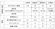
- Example 1 and Example 2 a foamed resin molded body molded by the molding method of the present invention and a foamed resin molded body molded by the molding method of the related art (Comparative Example 1 and Comparative Example below) Example 2) was compared.
- Comparative Example 1 since foaming is not performed, a resin molded body is molded instead of a foamed resin molded body.
- Example 1 10 parts by mass of the composite of the first nucleating agent (talc) and the second nucleating agent (calcium carbonate) and 3 parts by mass of the foaming agent with respect to 90 parts by mass of the polypropylene resin as the base material resin Mixing at a ratio, injection foam molding was performed so that the expansion ratio was doubled, and a foamed resin molded body was molded.
- the composite was obtained by high-speed stirring with a Henschel mixer in advance so that the talc content was 60% by mass and calcium carbonate was 40% by mass.
- the talc of the first nucleating agent has an average particle size of 3.2 ⁇ m, and the average particle size of calcium carbonate of the second nucleating agent is 80 nm.
- Example 2 The composite was composed of 75% talc and 25% calcium carbonate. Other than that was carried out similarly to Example 1, and shape
- Comparative Example 1 In Comparative Example 1, a resin molded body was molded by injection molding according to the related art using the polypropylene resin used as the base material resin in Example 1 and Example 2. The first nucleating agent, the second nucleating agent, and the foaming agent are not mixed, and foam injection molding is not performed.
- Comparative Example 2 In Comparative Example 2, a polypropylene resin is used as a base material resin as in Examples 1 and 2, and 3 parts by mass of the foaming agent and 10 parts of the first nucleating agent are used with respect to 90 parts by mass of the base material resin. The mixture was mixed at a ratio of part by mass, and injection foaming was performed so that the foaming ratio was doubled to form a foamed resin molded body. In addition, although talc was used as a 1st nucleating agent similarly to Example 1 and Example 2, the 2nd nucleating agent is not used. That is, Comparative Example 2 is related art foam injection molding.
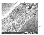
- FIG. 2 to 4 are enlarged photographs of the cross section of the foamed resin molded article of Example 1.
- FIG. 2 shows a magnification of 17 times
- FIG. 3 shows a magnification of 1000 times
- FIG. 4 shows a magnification of 3000 times
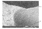
- 5 to 7 are enlarged photographs of the cross section of the foamed resin molded article of Comparative Example 2.
- FIG. 5 shows a magnification of 17 times
- FIG. 6 shows a magnification of 1000 times
- FIG. 7 shows a magnification of 3000 times. .
- Example 1 a foamed resin molded body 1 having a thickness of about 3 mm is molded, and a skin layer 2 having a thickness of about 0.2 to 0.6 mm is formed on the surface of the foamed resin molded body 1.
- the first foam cell 4 having a pore diameter of 10 to 500 ⁇ m (a foam cell that can be confirmed in the foam layer 3 in FIG. 2) is provided. It turns out that many are formed.
- Example 1 the pore diameter is approximately between the first foamed cells 4 (hereinafter referred to as “cell walls”) due to the second nucleating agent. It can be seen that a large number of fine second foam cells 5 of 10 to 1000 nm are formed. In addition, the small hole of the cell wall which can be confirmed in FIG. 3 and the small hole of the cell wall which can be confirmed in FIG. 4 are all the second foamed cells.
- a foamed resin molded body 11 having a thickness of about 3 mm is formed, and a skin layer 12 having a thickness of about 0.2 to 0.6 mm is formed on the surface of the foamed resin molded body 11. Yes. Due to the first nucleating agent, the foam layer 13 sandwiched between the skin layers 12 has a large number of first foam cells 14 having a pore diameter of 10 to 1000 ⁇ m (foam cells that can be confirmed in the foam layer 13 in FIG. 5). It can be seen that it is formed.
- Example 1 the fine foam cell which can be confirmed in Example 1 cannot be confirmed on the cell wall of the foamed resin molded body 11 of Comparative Example 2 in FIGS.
- the foamed resin molded body 1 of the present invention can make the first foamed cell 4 smaller than the foamed resin molded body 11 of the related art that does not use the second nucleating agent.
- a large number of very fine second foam cells 5 can be formed on the cell wall. That is, in the foamed resin molded body 1 of the present invention, the pore diameter of the foamed cells can be reduced and the number can be increased as compared with the foamed resin molded body 11 of the related art.
- the first foam cell 4 in the foamed resin molded body 1 of the present invention is smaller than the first foam cell 14 in the foamed resin molded body 11 of the related art.
- the amount of gas generated in the matrix resin by the blowing agent is the same.
- the generated gas generates bubbles due to the first nucleating agent.
- the fine second nucleating agent is used in addition to the first nucleating agent, a part of the generated gas is freed of bubbles due to the first nucleating agent. The other part of the generated gas is generated due to the second nucleating agent.
- the first foamed cell 4 is considered to be small.
- the particles of the second nucleating agent are very small and are uniformly dispersed in the base material resin, the bubbles generated due to the second nucleating agent are small, and the bubbles are combined to form large bubbles.
- the second foam cell 5 is small. From this, it is thought that the 2nd foaming cell 5 does not become large.
- the atmosphere was ⁇ 30 ° C., and a weight 34 having a spherical head with a radius of 25 mm and a mass of 500 g was dropped from above the center of the striking surface 33.
- This test was performed by changing the height h at which the weight 34 was dropped, and the test was performed five times for each height h. After dropping the weight 34, the state of the test piece 31 was observed, and the test piece 31 with no change or whitening was marked with “ ⁇ ”, and the cracked or broken one was marked with “X”. From this result, the height h at which the number of ⁇ was 50% was calculated, and the impact strength was calculated from the height h. The result is shown in FIG.
- the test machine was equipped with a support base and an indenter with a radius of 2 mm, and the test was carried out at a distance between supporting points of 100 mm and a test speed of 50 mm / s.
- the test results are average values of MD and TD and are shown in FIG.
- Comparative Example 1 which is a resin molded body obtained by simple injection molding
- Examples 1 and 2 and Comparative Example 2 which are foamed resin molded bodies
- the bending elastic gradient is compared with Comparative Example 1 which is a simple injection molded body.
- Examples 1 and 2 and Comparative Example 2 which are foamed resin moldings are significantly larger. That is, it can be seen that Examples 1 and 2 and Comparative Example 2 which are foamed resin molded bodies have significantly improved rigidity as compared with Comparative Example 1 which is a simple injection molded body.
- Example 1 and Example 2 The excellent impact resistance of Example 1 and Example 2 is considered to be due to the second foamed cell resulting from the nano-sized second nucleating agent.
- Example 1 and Example 2 are improved as compared to Comparative Example 2. That is, the design property is improved as compared with Comparative Example 2.
- the foamed resin molded body of the present invention can reduce the amount of coating compared to the foamed resin molded body of the related art, and can reduce the cost. Furthermore, products and applications to which the foamed resin molded body can be applied can be expanded.
- the weight ratio of the first nucleating agent to the second nucleating agent in the composite is preferably between 75:25 and 60:40. Moreover, it is preferable that 10 mass parts or more is mixed in the mixture with respect to 100 mass parts of base material resin.
Landscapes
- Chemical & Material Sciences (AREA)
- Engineering & Computer Science (AREA)
- Materials Engineering (AREA)
- Medicinal Chemistry (AREA)
- Health & Medical Sciences (AREA)
- Chemical Kinetics & Catalysis (AREA)
- Polymers & Plastics (AREA)
- Organic Chemistry (AREA)
- General Chemical & Material Sciences (AREA)
- Inorganic Chemistry (AREA)
- Manufacturing & Machinery (AREA)
- Mechanical Engineering (AREA)
- Manufacture Of Porous Articles, And Recovery And Treatment Of Waste Products (AREA)
- Injection Moulding Of Plastics Or The Like (AREA)
- Molding Of Porous Articles (AREA)
Abstract
Provided is a foamed resin molded article having a plurality of fine foam cells. The surfaces of this foamed resin molded article (1) are formed from a skin layer (2) and the inside is formed from a foam layer (3). A plurality of first foam cells (4) and a plurality of second foam cells (5), which are smaller than the first foam cells (4) and which are formed between groups of the first foam cells (4), are formed in the foam layer (3).
Description
本発明は、射出発泡成形法などにより成形される発泡樹脂成形体に関する。
The present invention relates to a foamed resin molded body molded by an injection foam molding method or the like.
現在、環境問題等の意識の高まりから、自動車を軽量化し、自動車の燃費を向上させることが求められている。そのため、ドアトリムなどの自動車部品の基材に軽量な発泡樹脂成形体を用いることにより、自動車の軽量化を図る場合がある。発泡樹脂成形体は、軽量化のほかに、材料コストの低減という観点からも好ましく、自動車部品での採用が増加傾向にある。
Currently, with the growing awareness of environmental issues, etc., it is required to reduce the weight of automobiles and improve the fuel efficiency of automobiles. For this reason, there is a case where the weight of the automobile is reduced by using a lightweight foamed resin molded body as a base material of an automobile part such as a door trim. Foamed resin moldings are preferable from the viewpoint of reducing material costs in addition to weight reduction, and their use in automobile parts tends to increase.
発泡樹脂成形体は、気泡(発泡セル)の割合が多い、即ち、発泡倍率が高いほど軽量であり、発泡樹脂成形体の発泡セルの径が小さいほど耐衝撃性などの物性に優れている。そのため、発泡樹脂成形体中に形成される発泡セルは、径が小さく、数が多いことが好ましい。
The foamed resin molded body has a higher proportion of bubbles (foamed cells), that is, the higher the foaming ratio, the lighter the weight, and the smaller the diameter of the foamed resin molded body, the better the physical properties such as impact resistance. Therefore, it is preferable that the foam cells formed in the foamed resin molded body have a small diameter and a large number.
発泡樹脂成形体の成形方法は、大きく分けて物理発泡と化学発泡の2つに分類される。
The molding method of the foamed resin molding is roughly divided into two types, physical foaming and chemical foaming.
物理発泡とは、射出成形機のシリンダー内で加圧された空気、炭酸ガス、窒素、あるいは揮発性溶媒を樹脂に溶解する方法である。
Physical foaming is a method in which air, carbon dioxide, nitrogen, or a volatile solvent pressurized in a cylinder of an injection molding machine is dissolved in a resin.
化学発泡とは、射出成形機のホッパー口から母材とともに化学発泡剤を投入して、熱分解もしくは化学反応により炭酸ガス、窒素、水、アンモニア等の気体を樹脂に混入させる方法である。
Chemical foaming is a method in which a chemical foaming agent is introduced together with a base material from a hopper port of an injection molding machine, and gases such as carbon dioxide, nitrogen, water, and ammonia are mixed into the resin by thermal decomposition or chemical reaction.
物理発泡においては、圧力や温度を容易に調整できるため、超臨界状態にした炭酸ガスや窒素を直接樹脂に注入できる。超臨界流体は液体のような圧縮性と気体のような拡散性があるため、炭酸ガスや窒素に高拡散性と高溶解性を付与できる。このことにより、発泡樹脂成形体中に形成される発泡セルは、径が小さく、数が多い発泡成形体を得ることができる。
In physical foaming, the pressure and temperature can be easily adjusted, so carbon dioxide and nitrogen in a supercritical state can be directly injected into the resin. Since supercritical fluid has compressibility like liquid and diffusibility like gas, it can impart high diffusivity and high solubility to carbon dioxide and nitrogen. As a result, the foamed cells formed in the foamed resin molded body have a small diameter and a large number of foamed molded bodies.
しかしながら、物理発泡は、気体の準備に加えて、気体を樹脂に溶解させる機構や、成形前に気体が樹脂から抜けないように圧力を維持する機構などが必要である。そのため、ユーザは新たな射出成形機を導入したり、既存の射出成形機を改造したりすることが必要となる。したがって、物理発泡による射出成形は、初期投資および維持費用等のコストが高いことが大きな課題となっている。
However, physical foaming requires, in addition to gas preparation, a mechanism for dissolving the gas in the resin and a mechanism for maintaining the pressure so that the gas does not escape from the resin before molding. Therefore, the user needs to introduce a new injection molding machine or remodel an existing injection molding machine. Therefore, the injection molding by physical foaming has a big problem that the initial investment and the cost of maintenance are high.
化学発泡においては化学反応によって気体を生成させるため、ガスを溶解させる圧力が低く、樹脂内にガスを多量に溶融させることは難しい。したがって発泡セルが大きくなってしまう。
In chemical foaming, gas is generated by a chemical reaction, so the pressure for dissolving the gas is low, and it is difficult to melt a large amount of gas in the resin. Therefore, the foam cell becomes large.
発泡射出成形においては発泡樹脂成形体中の発泡セルの孔径を小さくして、かつ発泡セルの数を多くすることを目的として、樹脂に造核剤を添加することが行われている。これは、気泡は物体の表面を起点として発生する、という特徴に基づいており、造核剤によって気泡の発生起点を増加させることができるため、化学発泡においては、造核剤は特に有効である。
In foam injection molding, a nucleating agent is added to a resin for the purpose of reducing the pore diameter of foamed cells in the foamed resin molded body and increasing the number of foamed cells. This is based on the feature that bubbles are generated starting from the surface of the object, and the generation point of bubbles can be increased by the nucleating agent. Therefore, the nucleating agent is particularly effective in chemical foaming. .
造核剤としては、従来からクエン酸系等の有機物が用いられている。しかし、これらの有機物は熱により分解が起こり、タール状の物質が生成される。化学発泡において、発泡剤が分解して気体を生成するためには、ある程度の高い温度が必要であり、その温度は、発泡剤の種類によっては、上記の有機物からなる造核剤が分解または劣化する温度以上となる場合もある。この場合、分解または劣化した造核剤が発泡樹脂成形体の表面の外観を損なったり、発泡セルを粗くしたり、さらには、臭いを生じる原因となったりして、発泡樹脂成形体の商品性が著しく低下してしまう。
As a nucleating agent, an organic substance such as a citric acid type has been conventionally used. However, these organic substances are decomposed by heat, and a tar-like substance is generated. In chemical foaming, in order for the foaming agent to decompose and produce gas, a certain high temperature is required. Depending on the type of foaming agent, the above nucleating agent composed of organic substances decomposes or deteriorates. In some cases, the temperature may be higher. In this case, the decomposed or deteriorated nucleating agent may impair the appearance of the surface of the foamed resin molded body, roughen the foamed cells, or cause odor. Will drop significantly.
また、発泡剤が分解して気体を生成する温度が、造核剤が分解または劣化する温度を越えない場合であっても、長期にわたって連続して成形を続けたときに、特に射出成形では、有機物からなる造核剤が劣化し、射出成形機のスクリュなどに徐々に付着していく。そのため、付着物によってスクリュの回転が妨げられたり、射出成形機の故障が引き起こされたりするため、このような有機物からなる造核剤を多量に使用することは好ましくない。
In addition, even when the temperature at which the foaming agent decomposes to generate gas does not exceed the temperature at which the nucleating agent decomposes or deteriorates, when molding is continued continuously over a long period of time, particularly in injection molding, The organic nucleating agent deteriorates and gradually adheres to the screw of the injection molding machine. For this reason, it is not preferable to use a large amount of such a nucleating agent made of an organic substance because the adhered matter prevents the rotation of the screw or causes a failure of the injection molding machine.
そこで、造核剤を熱に強くするために、造核剤として有機物ではなく無機物を用いたり、あるいは有機物と無機物とを併用したものを用いたりしている。
Therefore, in order to make the nucleating agent resistant to heat, not an organic substance but an inorganic substance or a combination of an organic substance and an inorganic substance is used as a nucleating agent.
化学発泡の一例を示している特許文献1には、溶融した樹脂に、発泡剤、および粒径2~50μm、特に好ましくは5~20μmの、造核剤となる炭酸カルシウム、タルク、あるいはマイカ等の無機化合物粉末を混入させることが示されている。
Patent Document 1 showing an example of chemical foaming includes a melted resin, a foaming agent, and calcium carbonate, talc, mica, or the like as a nucleating agent having a particle size of 2 to 50 μm, particularly preferably 5 to 20 μm. It is shown that the inorganic compound powder is mixed.
上記の特許文献1では、造核剤として、粒径が1~100μm程度の無機物のタルクなどが用いられている。この造核剤には、気泡数を増やす効果はあるものの、成形される発泡樹脂成形体に微細な発泡セルを多数有するセル構造を形成するには気泡数が十分ではない。
In the above Patent Document 1, an inorganic talc having a particle size of about 1 to 100 μm is used as a nucleating agent. Although this nucleating agent has an effect of increasing the number of bubbles, the number of bubbles is not sufficient to form a cell structure having a large number of fine foam cells in the molded foamed resin molded article.
また、図1Aおよび図1Bに示す気泡の成長過程からわかるように、発泡倍率を上げていくと、造核剤21の表面に多数の気泡22が生じ(図1A参照)、気泡の成長過程で複数の気泡22同士が結びつき、結局は大きな気泡23になってしまう(図1B参照)。そのため、化学発泡において、微細化した発泡セルを有する発泡樹脂成形体を実現することができていない。
Further, as can be seen from the bubble growth process shown in FIGS. 1A and 1B, when the expansion ratio is increased, a large number of bubbles 22 are generated on the surface of the nucleating agent 21 (see FIG. 1A). The plurality of bubbles 22 are connected to each other and eventually become a large bubble 23 (see FIG. 1B). Therefore, a foamed resin molded article having fine foam cells cannot be realized in chemical foaming.
本発明は、上記課題を鑑みてなされたものであり、微細な発泡セルを多数有する発泡樹脂成形体を提供することを目的とする。
This invention is made | formed in view of the said subject, and aims at providing the foamed resin molding which has many fine foam cells.
本発明の発泡樹脂成形体は、表面がスキン層で形成され、内部が発泡層で形成されている。発泡層には、複数の第1の発泡セルと、第1の発泡セル同士の間に形成され、かつ、第1の発泡セルより小さい複数の第2の発泡セルと、が形成されている。
The foamed resin molded body of the present invention has a surface formed of a skin layer and an interior formed of a foam layer. In the foam layer, a plurality of first foam cells and a plurality of second foam cells formed between the first foam cells and smaller than the first foam cells are formed.
本発明によれば、発泡樹脂成形体の発泡層に、微細な発泡セルを多数形成することができ、発泡樹脂成形体の耐衝撃性および剛性を向上させることができる。
According to the present invention, a large number of fine foam cells can be formed in the foam layer of the foamed resin molded body, and the impact resistance and rigidity of the foamed resin molded body can be improved.
以下に、添付の図面に基づき、本発明の実施の形態を説明する。なお、同一の機能を有する構成には添付図面中、同一の番号を付与し、その説明を省略することがある。
Hereinafter, embodiments of the present invention will be described with reference to the accompanying drawings. In addition, the same number is attached | subjected to the structure which has the same function in an accompanying drawing, and the description may be abbreviate | omitted.
本発明によって成形される発泡樹脂成形体は、母材樹脂となる熱可塑性樹脂に発泡剤を混合し、さらに、造核剤として、第1の造核剤の表面に第1の造核剤よりも平均粒径の小さい第2の造核剤を付着させて形成される複合体を混合したものを射出発泡成形することによって得られる。
The foamed resin molded body molded by the present invention is obtained by mixing a foaming agent with a thermoplastic resin as a base resin, and further, as a nucleating agent, on the surface of the first nucleating agent from the first nucleating agent. Is obtained by injection foaming a mixture of a composite formed by adhering a second nucleating agent having a small average particle size.
[母材樹脂]
本発明に用いられる母材樹脂としては、ポリプロピレンやポリエチレン等のポリオレフィン系樹脂が好適に用いられるが、これに限られるものではない。例えば、ポリスチレン、ABS(アクリロニトリル、ブタジエン、スチレン共重合合成)樹脂、AS(アクリロニトリル、スチレン共重合合成)樹脂等のポリスチレン系樹脂;ナイロン6、ナイロン66、ナイロン12等のポリアミド系樹脂;ポリエチレンテレフタレート(PET)、ポリブチレンテレフタレート(PBT)、ポリトリメチレンテレフタレート(PTT)、ポリエチレンナフタレート(PEN)、ポリ乳酸等のポリエステル系樹脂;ポリ塩化ビニル;ポリカーボネート(PC);ポリアセタール(POM);ポリイミド;ポリエーテルエーテルケトン(PEEK)、などを使用することができる。これらの母材樹脂は変性されていてもよい。また、2種以上の樹脂を併用しても良い。 [Base material resin]
As the base material resin used in the present invention, polyolefin resins such as polypropylene and polyethylene are preferably used, but are not limited thereto. For example, polystyrene resins such as polystyrene, ABS (acrylonitrile, butadiene, styrene copolymer synthesis) resin, AS (acrylonitrile, styrene copolymer synthesis) resin; polyamide resins such as nylon 6, nylon 66,nylon 12; polyethylene terephthalate ( PET), polybutylene terephthalate (PBT), polytrimethylene terephthalate (PTT), polyethylene naphthalate (PEN), polyester resins such as polylactic acid; polyvinyl chloride; polycarbonate (PC); polyacetal (POM); polyimide; Ether ether ketone (PEEK), etc. can be used. These matrix resins may be modified. Two or more kinds of resins may be used in combination.
本発明に用いられる母材樹脂としては、ポリプロピレンやポリエチレン等のポリオレフィン系樹脂が好適に用いられるが、これに限られるものではない。例えば、ポリスチレン、ABS(アクリロニトリル、ブタジエン、スチレン共重合合成)樹脂、AS(アクリロニトリル、スチレン共重合合成)樹脂等のポリスチレン系樹脂;ナイロン6、ナイロン66、ナイロン12等のポリアミド系樹脂;ポリエチレンテレフタレート(PET)、ポリブチレンテレフタレート(PBT)、ポリトリメチレンテレフタレート(PTT)、ポリエチレンナフタレート(PEN)、ポリ乳酸等のポリエステル系樹脂;ポリ塩化ビニル;ポリカーボネート(PC);ポリアセタール(POM);ポリイミド;ポリエーテルエーテルケトン(PEEK)、などを使用することができる。これらの母材樹脂は変性されていてもよい。また、2種以上の樹脂を併用しても良い。 [Base material resin]
As the base material resin used in the present invention, polyolefin resins such as polypropylene and polyethylene are preferably used, but are not limited thereto. For example, polystyrene resins such as polystyrene, ABS (acrylonitrile, butadiene, styrene copolymer synthesis) resin, AS (acrylonitrile, styrene copolymer synthesis) resin; polyamide resins such as nylon 6, nylon 66,
[発泡剤]
本発明に用いられる発泡剤としては、化学発泡剤による熱分解型あるいは反応型の発泡剤を使用する。具体的には、アゾジカルボンアミド等のアゾ化合物、N,N-ジニトロソペンタメチレンテトラミン等のニトロソ化合物、4,4’-オキシビス(ベンゼンスルホニルヒドラジド)、ヒドラゾジカルボンアミド等のヒドラジン誘導体、炭酸水素ナトリウム等の重炭酸塩、炭酸ナトリウム、炭酸アンモニウム等の炭酸塩、亜硝酸アンモニウム等の亜硝酸塩、セミカルバジド化合物、アジド化合物、テトラゾール化合物、イソシアネート化合物、あるいは、水酸化物などが好適に用いられ、また、尿素等の発泡助剤、クエン酸ナトリウム、タルク、あるいは炭酸カルシウム等の有機物系造核剤あるいは無機物系造核剤を併用添加してもよい。これらの発泡剤は2種類以上の発泡剤を併用しても良い。特に、炭酸水素ナトリウムと造核剤のクエン酸ナトリウムとをマスターバッチ化したものが好適に用いられる。 [Foaming agent]
As the foaming agent used in the present invention, a thermal decomposition type or reactive type foaming agent using a chemical foaming agent is used. Specifically, azo compounds such as azodicarbonamide, nitroso compounds such as N, N-dinitrosopentamethylenetetramine, hydrazine derivatives such as 4,4′-oxybis (benzenesulfonylhydrazide), hydrazodicarbonamide, hydrogen carbonate A bicarbonate such as sodium, a carbonate such as sodium carbonate or ammonium carbonate, a nitrite such as ammonium nitrite, a semicarbazide compound, an azide compound, a tetrazole compound, an isocyanate compound, or a hydroxide is preferably used. Foaming aids such as urea, organic nucleating agents such as sodium citrate, talc, or calcium carbonate or inorganic nucleating agents may be added in combination. These foaming agents may be used in combination of two or more kinds of foaming agents. In particular, a master batch of sodium hydrogen carbonate and sodium citrate, a nucleating agent, is preferably used.
[第1の造核剤]
上述したように、本発明の造核剤は、第1の造核剤と第1の造核剤よりも平均粒径の小さい第2の造核剤との複合体からなる。第1の造核剤と後述する第2の造核剤は、発泡樹脂成形体の発泡セルとなる気泡が発生する起点となる機能を有している。 [First nucleating agent]
As described above, the nucleating agent of the present invention comprises a complex of the first nucleating agent and the second nucleating agent having an average particle size smaller than that of the first nucleating agent. The 1st nucleating agent and the 2nd nucleating agent mentioned later have a function used as the starting point from which the bubble used as the foaming cell of a foaming resin molding is generated.
第1の造核剤としては、タルク、マイカ、シリカ、クレー、モンモリロナイト、カオリン等のケイ酸塩;炭酸カルシウム、炭酸リチウム、炭酸マグネシウム等の炭酸塩;アルミナ、酸化チタン、酸化亜鉛等の金属酸化物;アルミニウム、鉄、銀、銅等の金属;水酸化アルミニウム、水酸化マグネシウム等の水酸化物;硫酸バリウム等の硫化物;木炭、竹炭等の炭化物;チタン酸カリウム、チタン酸バリウム等のチタン化物、などが挙げられる。これらの中では、特に、タルクがより好ましい。
As the first nucleating agent, silicates such as talc, mica, silica, clay, montmorillonite and kaolin; carbonates such as calcium carbonate, lithium carbonate and magnesium carbonate; metal oxides such as alumina, titanium oxide and zinc oxide Metals such as aluminum, iron, silver and copper; hydroxides such as aluminum hydroxide and magnesium hydroxide; sulfides such as barium sulfate; carbides such as charcoal and bamboo charcoal; titanium such as potassium titanate and barium titanate And the like. Among these, talc is particularly preferable.
上述した無機物を用いた第1の造核剤の粒径は、0.5~1000μmであることが好ましく、1~10μmであることがより好ましい。粒径が0.5μm以上であれば、容易に第1の造核剤の微粒子を作製することができる。さらに、第1の造核剤の表面に多数のナノサイズ(1μm未満)の第2の造核剤を付着させることで、第1の造核剤を、母材樹脂内に第2の造核剤を分散させるためのキャリヤとして機能させることが可能となる。また、粒径が1000μm以下であれば、成形後の発泡樹脂成形体において、物性の低下や見栄えの悪化を防止することができる。
The particle size of the first nucleating agent using the inorganic material is preferably 0.5 to 1000 μm, more preferably 1 to 10 μm. If the particle size is 0.5 μm or more, the fine particles of the first nucleating agent can be easily produced. Furthermore, by attaching a large number of nano-sized (less than 1 μm) second nucleating agents to the surface of the first nucleating agent, the first nucleating agent is incorporated into the base resin. It becomes possible to function as a carrier for dispersing the agent. Moreover, if a particle size is 1000 micrometers or less, in the foamed resin molding after shaping | molding, the fall of a physical property and the deterioration of appearance can be prevented.
また、第1の造核剤としては、タルク等の無機物に替えて、植物繊維、セルロース繊維、酢酸セルロース繊維、ポリエチレンテレフタレート繊維、ナイロン繊維、ポリエチレンナフタレート繊維、アラミド繊維、ビニロン繊維、あるいはポリアリレート繊維などの繊維粉末を用いることができる。
In addition, as the first nucleating agent, plant fiber, cellulose fiber, cellulose acetate fiber, polyethylene terephthalate fiber, nylon fiber, polyethylene naphthalate fiber, aramid fiber, vinylon fiber, or polyarylate can be used instead of inorganic substances such as talc. Fiber powders such as fibers can be used.
この繊維粉末は、母材樹脂への分散性および接着性を向上させるために、芯鞘型、あるいはサイドバイサイド型等の複合繊維であっても良い。また、軽量化および耐熱性向上のために中空型の繊維であってもよい。
The fiber powder may be a core-sheath type or side-by-side type composite fiber in order to improve dispersibility and adhesion to the base resin. Moreover, a hollow fiber may be used for weight reduction and heat resistance improvement.
これらの繊維粉末は、平均繊維径が0.5~250μm、平均繊維長が1~3000μmの微細な繊維であることが望ましい。さらに、平均繊維径が1~100μm、平均繊維長が10~500μmであることが好ましく、平均繊維径が1~40μm、平均繊維長が20~300μmであることがさらに好ましい。
These fiber powders are desirably fine fibers having an average fiber diameter of 0.5 to 250 μm and an average fiber length of 1 to 3000 μm. Further, the average fiber diameter is preferably 1 to 100 μm and the average fiber length is preferably 10 to 500 μm, more preferably the average fiber diameter is 1 to 40 μm and the average fiber length is 20 to 300 μm.
[第2の造核剤]
第2の造核剤としては、例えば、タルク、シリカ、クレー、モンモリロナイト、カオリン等のケイ酸塩;炭酸カルシウム、炭酸リチウム、炭酸マグネシウム等の炭酸塩;アルミナ、酸化チタン、酸化亜鉛等の金属酸化物;アルミニウム、鉄、銀、銅等の金属;水酸化アルミニウム、水酸化マグネシウム等の水酸化物;硫酸バリウム等の硫化物;木炭、竹炭などの炭化物;チタン酸カリウム、チタン酸バリウム等のチタン化物;セルロースミクロフィブリル、酢酸セルロース等のセルロース類;フラーレン、カーボンナノチューブ等のカーボン類、などが挙げられる。これらの中の1種を単独で用いても良いし、2種以上を併用しても良い。これらの中では、炭酸カルシウム、マイカ、モンモリロナイト、酸化チタンが好ましい。特に、比較的容易にそして安価にナノサイズの粒子を作製または入手できる点から、炭酸カルシウムが好ましい。 [Second nucleating agent]
Examples of the second nucleating agent include silicates such as talc, silica, clay, montmorillonite, and kaolin; carbonates such as calcium carbonate, lithium carbonate, and magnesium carbonate; metal oxides such as alumina, titanium oxide, and zinc oxide. Metals such as aluminum, iron, silver and copper; hydroxides such as aluminum hydroxide and magnesium hydroxide; sulfides such as barium sulfate; carbides such as charcoal and bamboo charcoal; titanium such as potassium titanate and barium titanate And the like; celluloses such as cellulose microfibrils and cellulose acetate; carbons such as fullerenes and carbon nanotubes. One of these may be used alone, or two or more may be used in combination. Among these, calcium carbonate, mica, montmorillonite, and titanium oxide are preferable. In particular, calcium carbonate is preferred because nanosized particles can be produced or obtained relatively easily and inexpensively.
第2の造核剤の形状は、球状、板状、繊維状、中空状など、何れの形状でも良い。また、特定形状の微粒子を単独で用いても良いし、2種以上の異なる形状の微粒子を併用しても良い。なお、本発明の第2の造核剤には、一次粒子だけでなく、後述する第2の造核剤のサイズ(粒径)の範囲に入るものであれば、二次以上の粒子も含まれる。
The shape of the second nucleating agent may be any shape such as a spherical shape, a plate shape, a fiber shape, and a hollow shape. Moreover, fine particles having a specific shape may be used alone, or two or more kinds of fine particles having different shapes may be used in combination. The second nucleating agent of the present invention includes not only primary particles but also secondary or higher particles as long as they fall within the size (particle size) range of the second nucleating agent described later. It is.
第2の造核剤のサイズは、平均粒径が1μm未満のナノサイズであることが必要である。具体的には、その平均粒径は10~500nmである。平均粒径が10nm以上では、第2の造核剤の分散性を高める点で有利となり、平均粒径が500nm以下では、比表面積を増大させて気泡が発生する起点を増大させて発泡セルを微細化させる点で有利となる。第2の造核剤のサイズは、より好ましくは20~200nmであり、特に好ましくは50~100nmである。
The size of the second nucleating agent needs to be nano-sized with an average particle size of less than 1 μm. Specifically, the average particle diameter is 10 to 500 nm. When the average particle size is 10 nm or more, it is advantageous in terms of enhancing the dispersibility of the second nucleating agent, and when the average particle size is 500 nm or less, the specific surface area is increased to increase the starting point where bubbles are generated. This is advantageous in terms of miniaturization. The size of the second nucleating agent is more preferably 20 to 200 nm, and particularly preferably 50 to 100 nm.
[第1の造核剤と第2の造核剤の複合体]
第1の造核剤および第2の造核剤は、上述したように、第1の造核剤の表面に第2の造核剤が付着して形成される複合体で母材樹脂に混合される。 [Composite of first nucleating agent and second nucleating agent]
As described above, the first nucleating agent and the second nucleating agent are mixed with the base material resin in a complex formed by adhering the second nucleating agent to the surface of the first nucleating agent. Is done.
複合体の製造方法を説明すると、予め第1の造核剤と第2の造核剤をそれぞれ上述したサイズにまで粉砕、または析出法にて調整しておく。そして、第1の造核剤と第2の造核剤と後述する表面処理のためにステアリン酸とを一緒にヘンシェルミキサなどで高速撹拌することによって複合体が得られる。撹拌条件は、乾式で回転羽根の周速が20m/s以上であることが好ましい。これにより、ナノサイズの第2の造核剤が第1の造核剤の表面を覆うように付着され複合体が形成される。
Describing the production method of the composite, the first nucleating agent and the second nucleating agent are previously pulverized to the above-mentioned sizes or adjusted by the precipitation method. Then, the composite is obtained by stirring the first nucleating agent, the second nucleating agent, and stearic acid together with a Henschel mixer for surface treatment described later at a high speed. The stirring conditions are preferably dry and the peripheral speed of the rotary blade is 20 m / s or more. Thereby, the nano-sized second nucleating agent is attached so as to cover the surface of the first nucleating agent to form a complex.
[発泡樹脂成形体の成形方法]
次に、発泡樹脂成形体の成形方法の一例について説明する。この成形方法は一例にすぎず、この方法に限定されることはない。上述の母材樹脂と上述の複合体とを母材樹脂重量に対して複合体1~80質量%(より好ましくは3~50質量%、特に好ましくは5~20質量%)の割合で2軸混練押出機に投入して混練して混ぜ合わせる。このとき、複合体が母材樹脂内で、第1の造核剤と第2の造核剤とに分離して分散するため、第2の造核剤同士は独立して存在するようになり、第2の造核剤の再凝集が防止される。また、第2の造核剤が疎水性となるように、第2の造核剤にステアリン酸にて表面処理を行っているため、第2の造核剤と母材樹脂との親和性が高くなり、より再凝集しにくくなる。 [Molding method of foamed resin molding]
Next, an example of a molding method of the foamed resin molded body will be described. This forming method is merely an example, and the present invention is not limited to this method. The above-mentioned base material resin and the above-mentioned composite are biaxially formed at a ratio of 1 to 80% by mass (more preferably 3 to 50% by mass, particularly preferably 5 to 20% by mass) of the composite based on the weight of the base resin. Put into a kneading extruder and knead and mix. At this time, since the composite is separated and dispersed into the first nucleating agent and the second nucleating agent in the base material resin, the second nucleating agents come to exist independently. , Reaggregation of the second nucleating agent is prevented. In addition, since the second nucleating agent is surface-treated with stearic acid so that the second nucleating agent becomes hydrophobic, the affinity between the second nucleating agent and the base resin is high. It becomes high and it becomes difficult to re-aggregate.
混練の際、必要に応じて、さらに顔料、ゴム含有ポリマー、相溶化材、可塑剤、滑剤、難燃剤、抗菌剤、結晶化促進剤、酸化防止剤、紫外線吸収剤、熱安定剤、界面活性剤、帯電防止剤等の各種添加材を配合してもよい。
When kneading, if necessary, further pigments, rubber-containing polymers, compatibilizers, plasticizers, lubricants, flame retardants, antibacterial agents, crystallization accelerators, antioxidants, UV absorbers, heat stabilizers, surfactants You may mix | blend various additives, such as an agent and an antistatic agent.
複合体を母材樹脂に配合する方法としては、複合体を高濃度に樹脂に配合したマスターバッチを作製し、このマスターバッチをさらに樹脂に配合しても良い。
As a method of blending the composite with the base material resin, a master batch in which the composite is blended with the resin at a high concentration may be produced, and this master batch may be further blended with the resin.
そして、複合体が混ぜ合わされた母材樹脂および発泡剤、さらに、必要があれば、発泡樹脂成形体の所望のカラーバリエーションに対応した顔料入りのマスターバッチをドライブレンドする。
Then, a base material resin mixed with the composite and a foaming agent, and if necessary, a masterbatch containing a pigment corresponding to a desired color variation of the foamed resin molding is dry blended.
ドライブレンドされた混合物は射出成形機へと供給され、一定の圧力条件下で発泡剤の発泡を抑制した状態で、2つの金型によって形成される空間、つまりキャビティへ射出される。そして、スキン層が形成された後に一方の金型を他方の金型に対して後退させることで、混合物の密度が低下し、また圧力が開放される。いわゆるキャビティ拡張法である。これより、発泡剤が分解して、第1の造核剤と第2の造核剤の表面を起点に、炭酸ガスや窒素ガスなどの気泡が発生する。この気泡が発泡セルとなり、発泡層が形成され、発泡樹脂成形体が成形される。
The dry blended mixture is supplied to an injection molding machine, and is injected into a space formed by two molds, that is, cavities in a state where foaming of the foaming agent is suppressed under a certain pressure condition. Then, after the skin layer is formed, one mold is retracted with respect to the other mold, thereby reducing the density of the mixture and releasing the pressure. This is the so-called cavity expansion method. Thereby, the foaming agent is decomposed, and bubbles such as carbon dioxide gas and nitrogen gas are generated starting from the surfaces of the first nucleating agent and the second nucleating agent. This bubble becomes a foam cell, a foam layer is formed, and a foamed resin molded product is molded.
なお、発泡樹脂成形体の成形方法としては、ショートショット法、エグレッション法等を用いても良い。
It should be noted that a short shot method, an egress method, or the like may be used as a method for molding the foamed resin molded body.
上述したように、母材樹脂内に第1の造核剤と第2の造核剤とが均一に分散されている。そのため、本発明による発泡樹脂成形体においては、第1の造核剤の表面で発生した気泡による第1の発泡セル、および第2の造核剤の表面で発生した気泡による第2の発泡セルは、発泡樹脂成形体内で偏りなくほぼ均一に形成される。
As described above, the first nucleating agent and the second nucleating agent are uniformly dispersed in the base material resin. Therefore, in the foamed resin molded body according to the present invention, the first foamed cell due to the bubbles generated on the surface of the first nucleating agent and the second foamed cell due to the bubbles generated on the surface of the second nucleating agent. Is formed almost uniformly in the foamed resin molding.
次に、本発明の成形方法で成形された発泡樹脂成形体(以下の実施例1および実施例2)と、関連技術の成形方法で成形された発泡樹脂成形体(以下の比較例1および比較例2)とを比較した。ただし、比較例1では、発泡させていないので、発泡樹脂成形体ではなく、樹脂成形体が成形される。
Next, a foamed resin molded body (Example 1 and Example 2 below) molded by the molding method of the present invention and a foamed resin molded body molded by the molding method of the related art (Comparative Example 1 and Comparative Example below) Example 2) was compared. However, in Comparative Example 1, since foaming is not performed, a resin molded body is molded instead of a foamed resin molded body.
[実施例1]
母材樹脂であるポリプロピレン樹脂90質量部に対して、第1の造核剤(タルク)と第2の造核剤(炭酸カルシウム)との複合体を10質量部、発泡剤を3質量部の割合で混合し、発泡倍率が2倍となるように射出発泡成形を行い、発泡樹脂成形体を成形した。なお、複合体は、タルクが60質量%、炭酸カルシウム40質量%の割合となるように予めヘンシェルミキサで高速撹拌して得られた。第1の造核剤のタルクは、平均粒径が3.2μmであり、第2の造核剤の炭酸カルシウムの平均粒径は80nmである。 [Example 1]
10 parts by mass of the composite of the first nucleating agent (talc) and the second nucleating agent (calcium carbonate) and 3 parts by mass of the foaming agent with respect to 90 parts by mass of the polypropylene resin as the base material resin Mixing at a ratio, injection foam molding was performed so that the expansion ratio was doubled, and a foamed resin molded body was molded. The composite was obtained by high-speed stirring with a Henschel mixer in advance so that the talc content was 60% by mass and calcium carbonate was 40% by mass. The talc of the first nucleating agent has an average particle size of 3.2 μm, and the average particle size of calcium carbonate of the second nucleating agent is 80 nm.
[実施例2]
複合体は、タルク75%、炭酸カルシウム25%の割合とした。それ以外は実施例1と同様にして発泡樹脂成形体を成形した。 [Example 2]
The composite was composed of 75% talc and 25% calcium carbonate. Other than that was carried out similarly to Example 1, and shape | molded the foaming resin molding.
複合体は、タルク75%、炭酸カルシウム25%の割合とした。それ以外は実施例1と同様にして発泡樹脂成形体を成形した。 [Example 2]
The composite was composed of 75% talc and 25% calcium carbonate. Other than that was carried out similarly to Example 1, and shape | molded the foaming resin molding.
[比較例1]
比較例1では、実施例1および実施例2において母材樹脂として用いたポリプロピレン樹脂を用いて、関連技術の射出成形によって樹脂成形体を成形した。第1の造核剤、第2の造核剤、および発泡剤は混合しておらず、発泡射出成形は行っていない。 [Comparative Example 1]
In Comparative Example 1, a resin molded body was molded by injection molding according to the related art using the polypropylene resin used as the base material resin in Example 1 and Example 2. The first nucleating agent, the second nucleating agent, and the foaming agent are not mixed, and foam injection molding is not performed.
[比較例2]
比較例2では、実施例1および実施例2と同様にポリプロピレン樹脂を母材樹脂として用い、この母材樹脂90質量部に対して、発泡剤を3質量部、第1の造核剤を10質量部の割合で混合し、発泡倍率が2倍となるように射出発泡成形を行い、発泡樹脂成形体を成形した。なお、実施例1および実施例2と同様に第1の造核剤としてタルクを用いたが、第2の造核剤は使用していない。つまり、比較例2は、関連技術の発泡射出成形である。 [Comparative Example 2]
In Comparative Example 2, a polypropylene resin is used as a base material resin as in Examples 1 and 2, and 3 parts by mass of the foaming agent and 10 parts of the first nucleating agent are used with respect to 90 parts by mass of the base material resin. The mixture was mixed at a ratio of part by mass, and injection foaming was performed so that the foaming ratio was doubled to form a foamed resin molded body. In addition, although talc was used as a 1st nucleating agent similarly to Example 1 and Example 2, the 2nd nucleating agent is not used. That is, Comparative Example 2 is related art foam injection molding.
以上のようにして作成された実施例1の発泡樹脂成形体と、関連技術の成形方法で成形した比較例2の発泡樹脂成形体とを比較するために、マイクロスコープと走査型電子顕微鏡(SEM)による、発泡樹脂成形体の断面の観察を行った。
In order to compare the foamed resin molded article of Example 1 produced as described above with the foamed resin molded article of Comparative Example 2 molded by the molding method of the related art, a microscope and a scanning electron microscope (SEM) were used. The cross section of the foamed resin molded product was observed.
図2~図4は、実施例1の発泡樹脂成形体の断面の拡大写真であり、図2は倍率が17倍、図3は倍率が1000倍、図4は倍率が3000倍である。また、図5~図7は、比較例2の発泡樹脂成形体の断面の拡大写真であり、図5は倍率が17倍、図6は倍率が1000倍、図7は倍率が3000倍である。
2 to 4 are enlarged photographs of the cross section of the foamed resin molded article of Example 1. FIG. 2 shows a magnification of 17 times, FIG. 3 shows a magnification of 1000 times, and FIG. 4 shows a magnification of 3000 times. 5 to 7 are enlarged photographs of the cross section of the foamed resin molded article of Comparative Example 2. FIG. 5 shows a magnification of 17 times, FIG. 6 shows a magnification of 1000 times, and FIG. 7 shows a magnification of 3000 times. .
実施例1では、厚み約3mmの発泡樹脂成形体1が成形されており、発泡樹脂成形体1の表面には、厚みがおよそ0.2~0.6mmのスキン層2が形成されている。スキン層2に挟まれた発泡層3には、第1の造核剤に起因して、孔径が10~500μmの第1の発泡セル4(図2の発泡層3に確認できる発泡セル)が多数形成されていることがわかる。
In Example 1, a foamed resin molded body 1 having a thickness of about 3 mm is molded, and a skin layer 2 having a thickness of about 0.2 to 0.6 mm is formed on the surface of the foamed resin molded body 1. In the foam layer 3 sandwiched between the skin layers 2, due to the first nucleating agent, the first foam cell 4 having a pore diameter of 10 to 500 μm (a foam cell that can be confirmed in the foam layer 3 in FIG. 2) is provided. It turns out that many are formed.
また、図2~図4より、実施例1には、第1の発泡セル4同士の間(以降「セル壁」と称する)には、第2の造核剤に起因して、孔径がおよそ10~1000nmの微細な第2の発泡セル5が多数形成されていることがわかる。なお、図3で確認できるセル壁の小さな穴や、図4で確認できるセル壁の小さな穴は、いずれも第2の発泡セルである。
From FIG. 2 to FIG. 4, in Example 1, the pore diameter is approximately between the first foamed cells 4 (hereinafter referred to as “cell walls”) due to the second nucleating agent. It can be seen that a large number of fine second foam cells 5 of 10 to 1000 nm are formed. In addition, the small hole of the cell wall which can be confirmed in FIG. 3 and the small hole of the cell wall which can be confirmed in FIG. 4 are all the second foamed cells.
一方、比較例2では、厚み約3mmの発泡樹脂成形体11が成形されており、発泡樹脂成形体11の表面には、厚みがおよそ0.2~0.6mmのスキン層12が形成されている。スキン層12に挟まれた発泡層13には、第1の造核剤に起因して、孔径10~1000μmの第1の発泡セル14(図5の発泡層13に確認できる発泡セル)が多数形成されていることがわかる。
On the other hand, in Comparative Example 2, a foamed resin molded body 11 having a thickness of about 3 mm is formed, and a skin layer 12 having a thickness of about 0.2 to 0.6 mm is formed on the surface of the foamed resin molded body 11. Yes. Due to the first nucleating agent, the foam layer 13 sandwiched between the skin layers 12 has a large number of first foam cells 14 having a pore diameter of 10 to 1000 μm (foam cells that can be confirmed in the foam layer 13 in FIG. 5). It can be seen that it is formed.
また、図5~図7の比較例2の発泡樹脂成形体11のセル壁には、実施例1で確認できる微細な発泡セルが確認できない。
Moreover, the fine foam cell which can be confirmed in Example 1 cannot be confirmed on the cell wall of the foamed resin molded body 11 of Comparative Example 2 in FIGS.
以上のことより、本発明の発泡樹脂成形体1は、第2の造核剤を使用していない関連技術の発泡樹脂成形体11に比べて、第1の発泡セル4を小さくすることができ、また、セル壁には、極微細な第2の発泡セル5を多数形成することができる。つまり、関連技術の発泡樹脂成形体11に比べて、本発明の発泡樹脂成形体1では、発泡セルの孔径を小さくし、かつ数を増やすことができる。
From the above, the foamed resin molded body 1 of the present invention can make the first foamed cell 4 smaller than the foamed resin molded body 11 of the related art that does not use the second nucleating agent. In addition, a large number of very fine second foam cells 5 can be formed on the cell wall. That is, in the foamed resin molded body 1 of the present invention, the pore diameter of the foamed cells can be reduced and the number can be increased as compared with the foamed resin molded body 11 of the related art.
本発明の発泡樹脂成形体1における第1の発泡セル4は、関連技術の発泡樹脂成形体11における第1の発泡セル14よりも小さい理由を考察してみる。発泡剤によって母材樹脂内に発生するガスの量は同じであると仮定する。関連技術の発泡樹脂成形体11では、発生したガスは第1の造核剤に起因して気泡を生じる。一方、本発明では、第1の造核剤のほかに、微細な第2の造核剤を使用しているため、発生したガスの一部は第1の造核剤に起因して気泡を生じ、発生したガスの他の一部は第2の造核剤に起因して気泡を生じる。つまり、発生したガスは、第1の造核剤と第2の造核剤とに分散して気泡を生じることになるため、第1の発泡セル4が小さくなったと考えられる。また、第2の造核剤の粒子は非常に小さく、母材樹脂内に均一に分散しているため、第2の造核剤に起因して生じる気泡は小さく、気泡同士が結びついて大きな気泡になってしまうことが少なく、図3や図4からわかるように、第2の発泡セル5は小さい。このことから、第2の発泡セル5は大きくならないと考えられる。
Consider the reason why the first foam cell 4 in the foamed resin molded body 1 of the present invention is smaller than the first foam cell 14 in the foamed resin molded body 11 of the related art. Assume that the amount of gas generated in the matrix resin by the blowing agent is the same. In the foamed resin molding 11 of the related art, the generated gas generates bubbles due to the first nucleating agent. On the other hand, in the present invention, since the fine second nucleating agent is used in addition to the first nucleating agent, a part of the generated gas is freed of bubbles due to the first nucleating agent. The other part of the generated gas is generated due to the second nucleating agent. That is, since the generated gas is dispersed in the first nucleating agent and the second nucleating agent to generate bubbles, the first foamed cell 4 is considered to be small. In addition, since the particles of the second nucleating agent are very small and are uniformly dispersed in the base material resin, the bubbles generated due to the second nucleating agent are small, and the bubbles are combined to form large bubbles. As can be seen from FIGS. 3 and 4, the second foam cell 5 is small. From this, it is thought that the 2nd foaming cell 5 does not become large.
次に、実施例1、2および比較例1、2の物性の違いを調べた。はじめに試験方法について説明する。
Next, differences in physical properties between Examples 1 and 2 and Comparative Examples 1 and 2 were examined. First, the test method will be described.
(耐寒落球衝撃強さ)
試験片31は厚さ3mmの発泡樹脂成形体から長さ×幅=140mm×100mmに切り出したものを用いた。試験方法は、図8に示すように、試験片31の長さ方向の両端をそれぞれ20mm金属製の治具32に挟んで保持し、治具32から露出している部分である、長さ×幅=100mm×100mmの領域を打撃面33とした。なお、治具32には5Nのトルクをかけることで、試験片31を保持した。雰囲気は-30℃であり、半径25mmの球状頭部を持つ質量500gの錘34を打撃面33の中心の上方から落下させた。この試験は、錘34を落とす高さhを変えて行い、各高さhあたり5回試験を実施した。錘34を落下させた後、試験片31の状態を観察し、試験片31に変化が無いまたは白化したものを「○」、亀裂又は破壊したものを「×」とした。この結果から、○の数が50%になる高さhを算出し、この高さhより衝撃強さを算出した。その結果を図9に示している。 (Cold ball impact resistance)
Thetest piece 31 was cut from a foamed resin molded body having a thickness of 3 mm into length × width = 140 mm × 100 mm. As shown in FIG. 8, the test method is a portion of the length of the test piece 31 that is exposed from the jig 32 by holding both ends of the test piece 31 sandwiched between 20 mm metal jigs 32. An area of width = 100 mm × 100 mm was used as the striking surface 33. The test piece 31 was held by applying a torque of 5 N to the jig 32. The atmosphere was −30 ° C., and a weight 34 having a spherical head with a radius of 25 mm and a mass of 500 g was dropped from above the center of the striking surface 33. This test was performed by changing the height h at which the weight 34 was dropped, and the test was performed five times for each height h. After dropping the weight 34, the state of the test piece 31 was observed, and the test piece 31 with no change or whitening was marked with “◯”, and the cracked or broken one was marked with “X”. From this result, the height h at which the number of ◯ was 50% was calculated, and the impact strength was calculated from the height h. The result is shown in FIG.
試験片31は厚さ3mmの発泡樹脂成形体から長さ×幅=140mm×100mmに切り出したものを用いた。試験方法は、図8に示すように、試験片31の長さ方向の両端をそれぞれ20mm金属製の治具32に挟んで保持し、治具32から露出している部分である、長さ×幅=100mm×100mmの領域を打撃面33とした。なお、治具32には5Nのトルクをかけることで、試験片31を保持した。雰囲気は-30℃であり、半径25mmの球状頭部を持つ質量500gの錘34を打撃面33の中心の上方から落下させた。この試験は、錘34を落とす高さhを変えて行い、各高さhあたり5回試験を実施した。錘34を落下させた後、試験片31の状態を観察し、試験片31に変化が無いまたは白化したものを「○」、亀裂又は破壊したものを「×」とした。この結果から、○の数が50%になる高さhを算出し、この高さhより衝撃強さを算出した。その結果を図9に示している。 (Cold ball impact resistance)
The
(曲げ弾性勾配)
「JIS K 7171 プラスチック-曲げ特性の求め方」を試験方法として採用し、曲げ弾性勾配を測定した。試験片は、厚さ3mmの発泡樹脂成形体から、樹脂流れ方向(MD)と樹脂流れ方向に直交する直交方向(TD)とからそれぞれ長さ×幅=150mm×50mmに切り出したものを用いた。試験機には半径2mmの支持台および圧子を取り付け、支点間距離100mm、試験速度50mm/sで試験を実施した。試験結果は、MD、TDの平均値とし、図9に示している。 (Bending elastic gradient)
“JIS K 7171 plastic—how to obtain bending characteristics” was adopted as a test method, and the bending elastic gradient was measured. The test pieces used were cut from a foamed resin molded body having a thickness of 3 mm into a length × width = 150 mm × 50 mm from the resin flow direction (MD) and the orthogonal direction (TD) orthogonal to the resin flow direction. . The test machine was equipped with a support base and an indenter with a radius of 2 mm, and the test was carried out at a distance between supporting points of 100 mm and a test speed of 50 mm / s. The test results are average values of MD and TD and are shown in FIG.
(スワールマーク)
成形品の外観を目視にて観察し、スワールマークの有無について、以下の基準で評価した。なお、スワールマークは成形時にフローフロントで発泡が起こり、その気泡を引きずった跡が成形体の表面に外観不良として現れるものであり、発泡射出成形ではこの発生が避けられないが、発泡セル径が小さいほど目立ちにくくなる。以下の基準で評価した。「○」:問題無し、「△」:目立たない程度に(一部に)スワールマークがみられる、「×」:目立つ程度にスワールマークがみられる、である。試験結果を図9に示す。 (Swirl mark)
The appearance of the molded product was visually observed, and the presence or absence of a swirl mark was evaluated according to the following criteria. In addition, the swirl mark is foamed at the flow front during molding, and the trace of the bubbles appears as a defective appearance on the surface of the molded body, and this occurrence is unavoidable in foam injection molding, but the foam cell diameter is The smaller it is, the less noticeable. Evaluation was made according to the following criteria. “◯”: no problem, “Δ”: a swirl mark is seen to some extent (“partial”), “x”: a swirl mark is seen to a noticeable degree. The test results are shown in FIG.
(耐傷つき性)
成形品に、先端の直径が1mmの鋼鉄針を用い、500gの荷重をかけ、1000mm/minの引っかき速度で、2mmの間隔で碁盤目状に傷をつける。その後、成形品の外観を目視にて観察し傷つきの有無について、以下の基準で評価した。「○」:問題無し、「△」:目立たない程度に(一部に)傷がみられる、「×」:目立つ程度に傷がみられる、である。試験結果を図9に示す。 (Scratch resistance)
A steel needle having a tip diameter of 1 mm is applied to the molded product, a load of 500 g is applied, and scratches are made in a grid pattern at intervals of 2 mm at a scratching speed of 1000 mm / min. Thereafter, the appearance of the molded product was visually observed, and the presence or absence of scratches was evaluated according to the following criteria. “◯”: No problem, “Δ”: Inconspicuous (partly) flaws are observed, “×”: Conspicuous flaws are observed. The test results are shown in FIG.
単なる射出成形を行った樹脂成形体である比較例1と、発泡樹脂成形体である実施例1、2および比較例2を比較すると、曲げ弾性勾配は、単なる射出成形体である比較例1に比べて発泡樹脂成形体である実施例1、2および比較例2のほうが著しく大きい。つまり、発泡樹脂成形体である実施例1、2および比較例2は、単なる射出成形体である比較例1に比べて剛性が著しく向上することがわかる。
Comparing Comparative Example 1 which is a resin molded body obtained by simple injection molding, and Examples 1 and 2 and Comparative Example 2 which are foamed resin molded bodies, the bending elastic gradient is compared with Comparative Example 1 which is a simple injection molded body. In comparison, Examples 1 and 2 and Comparative Example 2 which are foamed resin moldings are significantly larger. That is, it can be seen that Examples 1 and 2 and Comparative Example 2 which are foamed resin molded bodies have significantly improved rigidity as compared with Comparative Example 1 which is a simple injection molded body.
比較例2と実施例1および実施例2とを比較すると、比較例2に比べて、実施例1および実施例2のほうが、衝撃に強いことがわかる。
Comparison of Comparative Example 2 with Example 1 and Example 2 shows that Example 1 and Example 2 are more resistant to impact than Comparative Example 2.
実施例1および実施例2の優れた耐衝撃性は、ナノサイズの第2の造核剤に起因する第2の発泡セルによるものと考えられる。
The excellent impact resistance of Example 1 and Example 2 is considered to be due to the second foamed cell resulting from the nano-sized second nucleating agent.
実施例1および実施例2のスワールマークおよび傷つき性は、比較例2に比べて改善されることがわかる。つまり、比較例2に比べて意匠性が向上する。これにより、本発明の発泡樹脂成形体は、関連技術の発泡樹脂成形体に比べて塗装量を削減可能となり、コストを削減することができる。さらに、発泡樹脂成形体を適応できる製品や用途を拡大させることができる。
It can be seen that the swirl marks and scratchability of Example 1 and Example 2 are improved as compared to Comparative Example 2. That is, the design property is improved as compared with Comparative Example 2. Thereby, the foamed resin molded body of the present invention can reduce the amount of coating compared to the foamed resin molded body of the related art, and can reduce the cost. Furthermore, products and applications to which the foamed resin molded body can be applied can be expanded.
以上の結果から、複合体における第1の造核剤と第2の造核剤との重量比は、75:25~60:40の間であることが好ましい。また、複合体は、母材樹脂100質量部に対して10質量部以上、混合物に混入されていることが好ましい。
From the above results, the weight ratio of the first nucleating agent to the second nucleating agent in the composite is preferably between 75:25 and 60:40. Moreover, it is preferable that 10 mass parts or more is mixed in the mixture with respect to 100 mass parts of base material resin.
本発明の特定の実施の形態についての上記説明は、例示を目的として提示したものである。それらは、記載した形態そのままに本発明を制限したりすることを意図したものではない。数多くの変形や変更が、上記の記載内容に照らして可能であることは当業者に自明である。
The above description of specific embodiments of the present invention has been presented for purposes of illustration. They are not intended to limit the invention to the precise form described. It will be apparent to those skilled in the art that many modifications and variations are possible in light of the above description.
この出願は、2011年4月28日に出願された日本出願特願2011-101712を基礎とする優先権を主張し、その開示の全てをここに取り込む。
This application claims priority based on Japanese Patent Application No. 2011-101712 filed on April 28, 2011, the entire disclosure of which is incorporated herein.
1、11 発泡樹脂成形体
2、12 スキン層
3、13 発泡層
4、14 第1の発泡セル
5 第2の発泡セル DESCRIPTION OF SYMBOLS 1, 11 Foamed resin molding 2, 12 Skin layer 3, 13 Foam layer 4, 14 1st foam cell 5 2nd foam cell
2、12 スキン層
3、13 発泡層
4、14 第1の発泡セル
5 第2の発泡セル DESCRIPTION OF
Claims (11)
- 表面を形成するスキン層と、
内部を形成する発泡層であって、複数の第1の発泡セルと、前記第1の発泡セル同士の間に形成され、前記第1の発泡セルより小さい複数の第2の発泡セルと、で形成される前記発泡層と、
を有する、発泡樹脂成形体。 A skin layer forming the surface;
A foam layer that forms an interior, and a plurality of first foam cells, and a plurality of second foam cells formed between the first foam cells and smaller than the first foam cells, The foamed layer to be formed;
A foamed resin molded article. - 前記第1の発泡セルの平均孔径が10~1000μmであり、前記第2の発泡セルの平均孔径が10~1000nmである、請求の範囲第1項に記載の発泡樹脂成形体。 2. The foamed resin molded article according to claim 1, wherein the average pore diameter of the first foam cell is 10 to 1000 μm, and the average pore diameter of the second foam cell is 10 to 1000 nm.
- 前記第1の発泡セルを形成させるための第1の造核剤と、前記第2の発泡セルを形成させるための第2の造核剤と、を有する請求の範囲第1項または第2項に記載の発泡樹脂成形体。 The first or second claim, comprising: a first nucleating agent for forming the first foamed cell; and a second nucleating agent for forming the second foamed cell. The foamed resin molded product according to 1.
- 第1の造核剤の表面に、前記第1の造核剤よりも小さな第2の造核剤を付着させて、前記第1の造核剤と前記第2の造核剤との複合体を形成する工程と、
樹脂と、発泡剤と、前記複合体とを混合して混合物を形成する工程と、
前記混合物を発泡射出成形する工程と、を含む、発泡樹脂成形体の成形方法。 A complex of the first nucleating agent and the second nucleating agent by attaching a second nucleating agent smaller than the first nucleating agent to the surface of the first nucleating agent. Forming a step;
Mixing a resin, a foaming agent, and the composite to form a mixture;
And a step of foaming and injection-molding the mixture. - 前記第1の造核剤の粒径は、0.5~1000μmであり、前記第2の造核剤の粒径は、10~500nmである、請求の範囲第4項に記載の発泡樹脂成形体の成形方法。 The foamed resin molding according to claim 4, wherein the particle size of the first nucleating agent is 0.5 to 1000 µm, and the particle size of the second nucleating agent is 10 to 500 nm. Body molding method.
- 前記第1の造核剤の粒径は、1~10μmであり、前記第2の造核剤の粒径は、50~100nmである、請求の範囲第5項に記載の発泡樹脂成形体の成形方法。 6. The foamed resin molded article according to claim 5, wherein the particle size of the first nucleating agent is 1 to 10 μm, and the particle size of the second nucleating agent is 50 to 100 nm. Molding method.
- 前記第1の造核剤および前記第2の造核剤は無機物である、請求の範囲第4項から第6項のいずれか1項に記載の発泡樹脂成形体の成形方法。 The method for molding a foamed resin molded article according to any one of claims 4 to 6, wherein the first nucleating agent and the second nucleating agent are inorganic substances.
- 前記第1の造核剤はタルクであり、前記第2の造核剤は炭酸カルシウムである、請求の範囲第7項に記載の発泡樹脂成形体の成形方法。 The method for molding a foamed resin molded article according to claim 7, wherein the first nucleating agent is talc and the second nucleating agent is calcium carbonate.
- 前記第2の造核剤は、疎水性を有するように表面処理されている、請求の範囲第4項から第8項のいずれか1項に記載の発泡樹脂成形体の成形方法。 The method for molding a foamed resin molded article according to any one of claims 4 to 8, wherein the second nucleating agent is surface-treated so as to have hydrophobicity.
- 前記複合体における、前記第1の造核剤と前記第2の造核剤との重量比は75:25~60:40の間である、請求の範囲第4項から第9項のいずれか1項に記載の発泡樹脂成形体の成形方法。 The weight ratio of the first nucleating agent to the second nucleating agent in the composite is between 75:25 and 60:40, according to any one of claims 4 to 9. 2. A method for molding a foamed resin molded article according to item 1.
- 前記複合体は、前記樹脂の質量に対して1~80質量%、前記混合物に混入されている、請求の範囲第4項から第10項のいずれか1項に記載の発泡樹脂成形体の成形方法。
11. The molding of the foamed resin molded body according to any one of claims 4 to 10, wherein the composite is mixed in the mixture in an amount of 1 to 80% by mass with respect to the mass of the resin. Method.
Priority Applications (1)
| Application Number | Priority Date | Filing Date | Title |
|---|---|---|---|
| US14/114,180 US20140044954A1 (en) | 2011-04-28 | 2012-04-12 | Foamed resin molded article |
Applications Claiming Priority (2)
| Application Number | Priority Date | Filing Date | Title |
|---|---|---|---|
| JP2011-101712 | 2011-04-28 | ||
| JP2011101712A JP5755016B2 (en) | 2011-04-28 | 2011-04-28 | Foamed resin molding |
Publications (1)
| Publication Number | Publication Date |
|---|---|
| WO2012147529A1 true WO2012147529A1 (en) | 2012-11-01 |
Family
ID=47072051
Family Applications (1)
| Application Number | Title | Priority Date | Filing Date |
|---|---|---|---|
| PCT/JP2012/060016 WO2012147529A1 (en) | 2011-04-28 | 2012-04-12 | Foamed resin molded article |
Country Status (3)
| Country | Link |
|---|---|
| US (1) | US20140044954A1 (en) |
| JP (1) | JP5755016B2 (en) |
| WO (1) | WO2012147529A1 (en) |
Cited By (8)
| Publication number | Priority date | Publication date | Assignee | Title |
|---|---|---|---|---|
| WO2014171430A1 (en) * | 2013-04-17 | 2014-10-23 | ユニチカ株式会社 | Molded foam |
| WO2014199276A1 (en) | 2013-06-12 | 2014-12-18 | Kimberly-Clark Worldwide, Inc. | Polymeric material for use in thermal insulation |
| WO2015019203A1 (en) | 2013-08-09 | 2015-02-12 | Kimberly-Clark Worldwide, Inc. | Flexible polymeric material with shape retention properties |
| CN105263996A (en) * | 2013-06-12 | 2016-01-20 | 金伯利-克拉克环球有限公司 | Pore initiation technique |
| CN105431479A (en) * | 2013-08-09 | 2016-03-23 | 金伯利-克拉克环球有限公司 | Technique for selectively controlling the porosity of a polymeric material |
| CN105492513A (en) * | 2013-08-09 | 2016-04-13 | 金伯利-克拉克环球有限公司 | Anisotropic polymeric material |
| US20160102185A1 (en) * | 2013-06-12 | 2016-04-14 | Kimberly-Clark Worldwide, Inc. | Polymeric Material with a Multimodal Pore Size Distribution |
| US20160120247A1 (en) * | 2013-06-12 | 2016-05-05 | Kimberly-Clark Worldwide, Inc. | Garment Containing a Porous Polymer Material |
Families Citing this family (15)
| Publication number | Priority date | Publication date | Assignee | Title |
|---|---|---|---|---|
| US10753023B2 (en) | 2010-08-13 | 2020-08-25 | Kimberly-Clark Worldwide, Inc. | Toughened polylactic acid fibers |
| US8975305B2 (en) | 2012-02-10 | 2015-03-10 | Kimberly-Clark Worldwide, Inc. | Rigid renewable polyester compositions having a high impact strength and tensile elongation |
| US11965083B2 (en) | 2013-06-12 | 2024-04-23 | Kimberly-Clark Worldwide, Inc. | Polyolefin material having a low density |
| RU2622830C1 (en) | 2013-06-12 | 2017-06-20 | Кимберли-Кларк Ворлдвайд, Инк. | Absorbent product, containing the porous polyolefin film |
| RU2630135C2 (en) * | 2013-08-09 | 2017-09-05 | Кимберли-Кларк Ворлдвайд, Инк. | Microparticles, characterized by multimodal pore distribution |
| RU2016148475A (en) * | 2014-06-06 | 2018-06-09 | Кимберли-Кларк Ворлдвайд, Инк. | THERMOFORMED PRODUCT FORMED FROM POROUS POLYMERIC SHEET |
| GB2549412B8 (en) | 2014-11-26 | 2021-07-07 | Kimberly Clark Co | Annealed porous polyolefin material |
| AU2015380472B2 (en) | 2015-01-30 | 2021-08-12 | Kimberly-Clark Worldwide, Inc. | Film with reduced noise for use in an absorbent article |
| MX2017009137A (en) | 2015-01-30 | 2017-11-22 | Kimberly Clark Co | Absorbent article package with reduced noise. |
| JP6043897B1 (en) * | 2015-11-06 | 2016-12-14 | バンドー化学株式会社 | Method for producing foam molded article and foam molded article |
| EP3372379B1 (en) * | 2015-11-06 | 2021-03-31 | Bando Chemical Industries, Ltd. | Molded-foam production process and molded foam |
| US11992980B2 (en) | 2016-03-11 | 2024-05-28 | Toyota Boshoku Kabushiki Kaisha | Foamed resin molded article and method for manufacturing same |
| WO2021015191A1 (en) * | 2019-07-23 | 2021-01-28 | サンアロマー株式会社 | Expandable polypropylene composition and injection molded foam |
| CN112092277B (en) * | 2020-08-05 | 2022-02-25 | 江苏佳境生态工程技术有限公司 | Process for manufacturing permeable plastic road surface layer particles |
| WO2022220148A1 (en) * | 2021-04-15 | 2022-10-20 | 株式会社プライムポリマー | Injection foam molded body |
Citations (4)
| Publication number | Priority date | Publication date | Assignee | Title |
|---|---|---|---|---|
| JP2002079545A (en) * | 2000-06-22 | 2002-03-19 | Mitsui Chemicals Inc | Injection foaming molding method, injection molding machine and resin composition suitable for the method |
| WO2003018677A1 (en) * | 2001-08-31 | 2003-03-06 | Honda Motor Co., Ltd. | Thermoplastic elastomer composition for core back type injection foaming and injection foaming method using the same |
| WO2006080491A1 (en) * | 2005-01-31 | 2006-08-03 | Jsr Corporation | Method of forming molded foam and molded foam |
| JP2008024914A (en) * | 2006-06-22 | 2008-02-07 | Jsr Corp | Foamed molded product and process for its production |
Family Cites Families (6)
| Publication number | Priority date | Publication date | Assignee | Title |
|---|---|---|---|---|
| HUP0402556A3 (en) * | 2002-01-04 | 2008-07-28 | Dow Global Technologies Inc | Multimodal polymeric foam containing an absorbent clay |
| US8568632B2 (en) * | 2003-11-26 | 2013-10-29 | Owens Corning Intellectual Capital, Llc | Method of forming thermoplastic foams using nano-particles to control cell morphology |
| EP2125320A2 (en) * | 2007-03-12 | 2009-12-02 | The University of Washington | Foaming methods for making cellular thermoplastic materials |
| EP2251373B1 (en) * | 2008-03-07 | 2013-08-28 | Toray Industries, Inc. | Heat-insulating material |
| US8507568B2 (en) * | 2008-05-28 | 2013-08-13 | The Ohio State University | Suspension polymerization and foaming of water containing activated carbon-nano/microparticulate polymer composites |
| EP2504384B1 (en) * | 2009-11-25 | 2018-03-21 | Dow Global Technologies LLC | Nanoporous polymeric foam having high porosity |
-
2011
- 2011-04-28 JP JP2011101712A patent/JP5755016B2/en active Active
-
2012
- 2012-04-12 WO PCT/JP2012/060016 patent/WO2012147529A1/en active Application Filing
- 2012-04-12 US US14/114,180 patent/US20140044954A1/en not_active Abandoned
Patent Citations (4)
| Publication number | Priority date | Publication date | Assignee | Title |
|---|---|---|---|---|
| JP2002079545A (en) * | 2000-06-22 | 2002-03-19 | Mitsui Chemicals Inc | Injection foaming molding method, injection molding machine and resin composition suitable for the method |
| WO2003018677A1 (en) * | 2001-08-31 | 2003-03-06 | Honda Motor Co., Ltd. | Thermoplastic elastomer composition for core back type injection foaming and injection foaming method using the same |
| WO2006080491A1 (en) * | 2005-01-31 | 2006-08-03 | Jsr Corporation | Method of forming molded foam and molded foam |
| JP2008024914A (en) * | 2006-06-22 | 2008-02-07 | Jsr Corp | Foamed molded product and process for its production |
Cited By (24)
| Publication number | Priority date | Publication date | Assignee | Title |
|---|---|---|---|---|
| JPWO2014171430A1 (en) * | 2013-04-17 | 2017-02-23 | ユニチカ株式会社 | Foam molding |
| WO2014171430A1 (en) * | 2013-04-17 | 2014-10-23 | ユニチカ株式会社 | Molded foam |
| AU2014279700B2 (en) * | 2013-06-12 | 2017-09-14 | Kimberly-Clark Worldwide, Inc. | Polymeric material with a multimodal pore size distribution |
| CN105263996A (en) * | 2013-06-12 | 2016-01-20 | 金伯利-克拉克环球有限公司 | Pore initiation technique |
| EP3008120A4 (en) * | 2013-06-12 | 2017-01-25 | Kimberly-Clark Worldwide, Inc. | Polymeric material for use in thermal insulation |
| US11286362B2 (en) * | 2013-06-12 | 2022-03-29 | Kimberly-Clark Worldwide, Inc. | Polymeric material for use in thermal insulation |
| US11084916B2 (en) * | 2013-06-12 | 2021-08-10 | Kimberly-Clark Worldwide, Inc. | Polymeric material with a multimodal pore size distribution |
| WO2014199276A1 (en) | 2013-06-12 | 2014-12-18 | Kimberly-Clark Worldwide, Inc. | Polymeric material for use in thermal insulation |
| US20160102185A1 (en) * | 2013-06-12 | 2016-04-14 | Kimberly-Clark Worldwide, Inc. | Polymeric Material with a Multimodal Pore Size Distribution |
| US20160122491A1 (en) * | 2013-06-12 | 2016-05-05 | Kimberly-Clark Worldwide, Inc. | Polymeric Material for Use in Thermal Insulation |
| CN105246955A (en) * | 2013-06-12 | 2016-01-13 | 金伯利-克拉克环球有限公司 | Polymeric material for use in thermal insulation |
| US20160120247A1 (en) * | 2013-06-12 | 2016-05-05 | Kimberly-Clark Worldwide, Inc. | Garment Containing a Porous Polymer Material |
| US11434340B2 (en) | 2013-08-09 | 2022-09-06 | Kimberly-Clark Worldwide, Inc. | Flexible polymeric material with shape retention properties |
| EP3030605A4 (en) * | 2013-08-09 | 2017-03-22 | Kimberly-Clark Worldwide, Inc. | Flexible polymeric material with shape retention properties |
| KR20160042974A (en) * | 2013-08-09 | 2016-04-20 | 킴벌리-클라크 월드와이드, 인크. | Flexible polymeric material with shape retention properties |
| EP3030606A4 (en) * | 2013-08-09 | 2017-03-22 | Kimberly-Clark Worldwide, Inc. | Anisotropic polymeric material |
| AU2014304179B2 (en) * | 2013-08-09 | 2017-08-17 | Kimberly-Clark Worldwide, Inc. | Anisotropic polymeric material |
| AU2014304181B2 (en) * | 2013-08-09 | 2017-08-17 | Kimberly-Clark Worldwide, Inc. | Flexible polymeric material with shape retention properties |
| CN105492513A (en) * | 2013-08-09 | 2016-04-13 | 金伯利-克拉克环球有限公司 | Anisotropic polymeric material |
| CN105408403B (en) * | 2013-08-09 | 2018-12-21 | 金伯利-克拉克环球有限公司 | Flexible polymeric material with shape retention |
| CN105431479A (en) * | 2013-08-09 | 2016-03-23 | 金伯利-克拉克环球有限公司 | Technique for selectively controlling the porosity of a polymeric material |
| KR102334602B1 (en) | 2013-08-09 | 2021-12-06 | 킴벌리-클라크 월드와이드, 인크. | Flexible polymeric material with shape retention properties |
| CN105408403A (en) * | 2013-08-09 | 2016-03-16 | 金伯利-克拉克环球有限公司 | Flexible polymeric material with shape retention properties |
| WO2015019203A1 (en) | 2013-08-09 | 2015-02-12 | Kimberly-Clark Worldwide, Inc. | Flexible polymeric material with shape retention properties |
Also Published As
| Publication number | Publication date |
|---|---|
| JP2012233055A (en) | 2012-11-29 |
| US20140044954A1 (en) | 2014-02-13 |
| JP5755016B2 (en) | 2015-07-29 |
Similar Documents
| Publication | Publication Date | Title |
|---|---|---|
| JP5755016B2 (en) | Foamed resin molding | |
| Altan | Thermoplastic foams: Processing, manufacturing, and characterization | |
| WO1997029896A1 (en) | A method of forming a light-weight, fiber-reinforced thermoplastic resin product and a light-weight molded product | |
| US20050048276A1 (en) | Structural foam composite having nano-particle reinforcement and method of making the same | |
| JPH0511745B2 (en) | ||
| WO2018047754A1 (en) | Process for producing sheet | |
| JP5280725B2 (en) | Method for producing injection foam | |
| JP5479772B2 (en) | Foam molded body and method for producing the same | |
| JP2017177669A (en) | Method for producing foam resin molded article, and foam resin molded article | |
| JP4612266B2 (en) | Thermoplastic resin molded article excellent in wood texture and method for producing the same | |
| JP2014172381A (en) | Foamed resin made plate and production method thereof | |
| JP6551146B2 (en) | Foam molded body and method for producing the same, and method for producing resin material for foam molded body | |
| JPH03170536A (en) | Use of polyarylene sulfide for manufacture of high temperature- resistant structural foam, manu- facture of this foam and molded product which can be obtained using this method | |
| JP2010120335A (en) | Method of manufacturing moisture-proof light-weighted resin molding | |
| JP4684304B2 (en) | Method for producing resin foam and resin foam | |
| JP4573505B2 (en) | Method for producing resin foam and resin foam | |
| JP3307721B2 (en) | Manufacturing method of automotive interior parts made of composite molded body | |
| JP4263539B2 (en) | Extrusion method of thermoplastic resin, extruded product | |
| JP2007210339A (en) | Manufacturing method of foamed resin extrusion molded article with covering sheet | |
| JP2013082117A (en) | Method for producing lightweight wood plastic foam molding | |
| JP2007276245A (en) | Method for producing foamed resin-extruded body | |
| JP2022141139A (en) | foam structure | |
| JP2008062405A (en) | Foamed resin extrusion-molded object and its manufacturing method | |
| JP3815883B2 (en) | Inkjet recording film | |
| WO2021161586A1 (en) | Molded body, and method for producing molded body |
Legal Events
| Date | Code | Title | Description |
|---|---|---|---|
| 121 | Ep: the epo has been informed by wipo that ep was designated in this application |
Ref document number: 12777145 Country of ref document: EP Kind code of ref document: A1 |
|
| WWE | Wipo information: entry into national phase |
Ref document number: 14114180 Country of ref document: US |
|
| NENP | Non-entry into the national phase |
Ref country code: DE |
|
| 122 | Ep: pct application non-entry in european phase |
Ref document number: 12777145 Country of ref document: EP Kind code of ref document: A1 |