WO2012147459A1 - 多目的ガス溶解装置 - Google Patents
多目的ガス溶解装置 Download PDFInfo
- Publication number
- WO2012147459A1 WO2012147459A1 PCT/JP2012/058928 JP2012058928W WO2012147459A1 WO 2012147459 A1 WO2012147459 A1 WO 2012147459A1 JP 2012058928 W JP2012058928 W JP 2012058928W WO 2012147459 A1 WO2012147459 A1 WO 2012147459A1
- Authority
- WO
- WIPO (PCT)
- Prior art keywords
- pipe
- tube
- diameter
- connecting pipe
- diameter inner
- Prior art date
- Legal status (The legal status is an assumption and is not a legal conclusion. Google has not performed a legal analysis and makes no representation as to the accuracy of the status listed.)
- Ceased
Links
Images


Classifications
-
- A—HUMAN NECESSITIES
- A61—MEDICAL OR VETERINARY SCIENCE; HYGIENE
- A61H—PHYSICAL THERAPY APPARATUS, e.g. DEVICES FOR LOCATING OR STIMULATING REFLEX POINTS IN THE BODY; ARTIFICIAL RESPIRATION; MASSAGE; BATHING DEVICES FOR SPECIAL THERAPEUTIC OR HYGIENIC PURPOSES OR SPECIFIC PARTS OF THE BODY
- A61H33/00—Bathing devices for special therapeutic or hygienic purposes
- A61H33/60—Components specifically designed for the therapeutic baths of groups A61H33/00
-
- B—PERFORMING OPERATIONS; TRANSPORTING
- B01—PHYSICAL OR CHEMICAL PROCESSES OR APPARATUS IN GENERAL
- B01F—MIXING, e.g. DISSOLVING, EMULSIFYING OR DISPERSING
- B01F23/00—Mixing according to the phases to be mixed, e.g. dispersing or emulsifying
- B01F23/20—Mixing gases with liquids
- B01F23/23—Mixing gases with liquids by introducing gases into liquid media, e.g. for producing aerated liquids
- B01F23/232—Mixing gases with liquids by introducing gases into liquid media, e.g. for producing aerated liquids using flow-mixing means for introducing the gases, e.g. baffles
- B01F23/2323—Mixing gases with liquids by introducing gases into liquid media, e.g. for producing aerated liquids using flow-mixing means for introducing the gases, e.g. baffles by circulating the flow in guiding constructions or conduits
-
- B—PERFORMING OPERATIONS; TRANSPORTING
- B01—PHYSICAL OR CHEMICAL PROCESSES OR APPARATUS IN GENERAL
- B01F—MIXING, e.g. DISSOLVING, EMULSIFYING OR DISPERSING
- B01F23/00—Mixing according to the phases to be mixed, e.g. dispersing or emulsifying
- B01F23/20—Mixing gases with liquids
- B01F23/23—Mixing gases with liquids by introducing gases into liquid media, e.g. for producing aerated liquids
- B01F23/237—Mixing gases with liquids by introducing gases into liquid media, e.g. for producing aerated liquids characterised by the physical or chemical properties of gases or vapours introduced in the liquid media
- B01F23/2376—Mixing gases with liquids by introducing gases into liquid media, e.g. for producing aerated liquids characterised by the physical or chemical properties of gases or vapours introduced in the liquid media characterised by the gas being introduced
- B01F23/23762—Carbon dioxide
-
- B—PERFORMING OPERATIONS; TRANSPORTING
- B01—PHYSICAL OR CHEMICAL PROCESSES OR APPARATUS IN GENERAL
- B01F—MIXING, e.g. DISSOLVING, EMULSIFYING OR DISPERSING
- B01F25/00—Flow mixers; Mixers for falling materials, e.g. solid particles
- B01F25/40—Static mixers
- B01F25/42—Static mixers in which the mixing is affected by moving the components jointly in changing directions, e.g. in tubes provided with baffles or obstructions
- B01F25/421—Static mixers in which the mixing is affected by moving the components jointly in changing directions, e.g. in tubes provided with baffles or obstructions by moving the components in a convoluted or labyrinthine path
- B01F25/423—Static mixers in which the mixing is affected by moving the components jointly in changing directions, e.g. in tubes provided with baffles or obstructions by moving the components in a convoluted or labyrinthine path by means of elements placed in the receptacle for moving or guiding the components
-
- B—PERFORMING OPERATIONS; TRANSPORTING
- B01—PHYSICAL OR CHEMICAL PROCESSES OR APPARATUS IN GENERAL
- B01F—MIXING, e.g. DISSOLVING, EMULSIFYING OR DISPERSING
- B01F25/00—Flow mixers; Mixers for falling materials, e.g. solid particles
- B01F25/40—Static mixers
- B01F25/45—Mixers in which the materials to be mixed are pressed together through orifices or interstitial spaces, e.g. between beads
- B01F25/452—Mixers in which the materials to be mixed are pressed together through orifices or interstitial spaces, e.g. between beads characterised by elements provided with orifices or interstitial spaces
- B01F25/4521—Mixers in which the materials to be mixed are pressed together through orifices or interstitial spaces, e.g. between beads characterised by elements provided with orifices or interstitial spaces the components being pressed through orifices in elements, e.g. flat plates or cylinders, which obstruct the whole diameter of the tube
- B01F25/45211—Mixers in which the materials to be mixed are pressed together through orifices or interstitial spaces, e.g. between beads characterised by elements provided with orifices or interstitial spaces the components being pressed through orifices in elements, e.g. flat plates or cylinders, which obstruct the whole diameter of the tube the elements being cylinders or cones which obstruct the whole diameter of the tube, the flow changing from axial in radial and again in axial
-
- A—HUMAN NECESSITIES
- A61—MEDICAL OR VETERINARY SCIENCE; HYGIENE
- A61H—PHYSICAL THERAPY APPARATUS, e.g. DEVICES FOR LOCATING OR STIMULATING REFLEX POINTS IN THE BODY; ARTIFICIAL RESPIRATION; MASSAGE; BATHING DEVICES FOR SPECIAL THERAPEUTIC OR HYGIENIC PURPOSES OR SPECIFIC PARTS OF THE BODY
- A61H33/00—Bathing devices for special therapeutic or hygienic purposes
- A61H33/02—Bathing devices for use with gas-containing liquid, or liquid in which gas is led or generated, e.g. carbon dioxide baths
-
- B—PERFORMING OPERATIONS; TRANSPORTING
- B01—PHYSICAL OR CHEMICAL PROCESSES OR APPARATUS IN GENERAL
- B01F—MIXING, e.g. DISSOLVING, EMULSIFYING OR DISPERSING
- B01F25/00—Flow mixers; Mixers for falling materials, e.g. solid particles
- B01F2025/91—Direction of flow or arrangement of feed and discharge openings
- B01F2025/915—Reverse flow, i.e. flow changing substantially 180° in direction
Definitions
- the present invention relates to a multipurpose gas dissolving apparatus that artificially generates carbonated spring by dissolving carbon dioxide gas in sodium hypochlorite water or warm water.
- Carbon dioxide gas can be efficiently dissolved with a simple structure, and high-concentration carbonated hot water can be easily produced even when water is supplied from a water heater with low hot water pressure.
- Carbonate springs are automatically generated just by opening and closing the faucet.
- a convenient carbonated spring generation method and apparatus are known (see Patent Document 1).
- This known technique has a pressure vessel such as a tank, has a carbon dioxide space above the pressure vessel, and vigorously injects hot water sent from the top of the vessel by a water heater or water pump into the vessel.
- the flow is stored in the container, and the carbon dioxide gas is entrained and collides with the hot water, so that the hot water in the container bubbles with the carbon dioxide gas, greatly increasing the contact area between the hot water and the carbon dioxide gas, and relatively low pressure
- This is a carbonated spring production method and apparatus that efficiently dissolves carbon dioxide gas in warm water even underneath.
- Patent Document 2 a carbonated spring generating device
- Patent Document 3 a gas dissolution production device
- a carbon dioxide gas generator comprising a carbon dioxide gas supply means, a liquid supply means, and a carbon dioxide gas dissolver connected to the carbon dioxide gas supply means and the liquid supply means.
- the vessel is formed of a tube material in which bellows-like irregularities are continuously formed in the longitudinal direction on the inner diameter side, and is connected to an outer flow path in which the tube material is wound in a coil shape and an end portion of the outer flow path folded back.
- a carbonated spring generating apparatus and a gas dissolving manufacturing apparatus that are configured to include an inner flow path in which a tube material is wound in a coil shape inside the outer flow path, and that supplies hot water supplied from the liquid supply means instead of carbonated spring.
- An object of the present invention is to provide a multi-purpose gas dissolving apparatus that generates a carbonated spring artificially by dissolving carbon dioxide efficiently in sodium hypochlorite water or warm water with a simple structure.
- the multipurpose gas dissolving apparatus of the present invention has an upper connecting pipe having a concentric fitting tube having a threaded portion at the tip and a flow passage on the inside, a screw portion at the lower end, and a flow passage on the inside.
- a lower connecting pipe having a concentric double cylinder, a straight cylindrical outer pipe connected to the upper connecting pipe and the lower connecting pipe, and a small diameter fitted to the fitting cylinder of the upper connecting pipe
- An inner tube and a large-diameter inner tube formed integrally with the small-diameter inner tube via a tapered surface are provided, and the container-like inner tube is built in the outer tube.
- a gap of 0.01 to 10 mm is formed between the inner diameter of the outer tube and the outer diameter of the large inner tube. The dimension is such that a height space of 100 mm is formed between the bottom surface of the large-diameter inner tube and the top surface of the lower connecting tube.
- the multipurpose gas dissolving apparatus of the present invention has an upper connecting pipe having a concentric fitting tube having a threaded portion at the tip and a flow passage on the inside, a screw portion at the lower end, and a flow passage on the inside.
- a lower connecting pipe having a concentric double cylinder, a straight cylindrical outer pipe connected to the upper connecting pipe and the lower connecting pipe, and a small diameter fitted to the fitting cylinder of the upper connecting pipe Since it comprises an inner tube and a large-diameter inner tube formed integrally with the small-diameter inner tube via a tapered surface, and is composed of a container-like inner tube built in the outer tube,
- the structure has an effect that carbon dioxide can be efficiently dissolved in sodium hypochlorite water or warm water to artificially generate a carbonated spring.
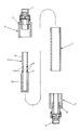
- FIG. 1 is an exploded cross-sectional view of a multipurpose gas dissolving device of the present invention. It is an expanded sectional view of the upper part of the multipurpose gas dissolving device of the present invention. It is an expanded sectional view of the lower part of the multipurpose gas dissolving device of the present invention.
- the multipurpose gas dissolving apparatus of the present invention has an upper connecting pipe 3 having a concentric fitting cylinder 2 having a screw part 1 at the tip and a flow passage inside.
- a lower connecting pipe 6 having a concentric double cylinder 5 having a threaded portion 4 at the lower end and a flow passage on the inner side, and being connected to the upper connecting pipe 3 and the lower connecting pipe 6 to be fitted inside.
- An inner pipe 10 is provided, and the container-like inner pipe 11 is built in the outer pipe 7.
- the upper connecting pipe 3 has a cap shape and supplies a gas-liquid mixed fluid of sodium hypochlorite water or warm water and carbon dioxide (not shown). And a concentric fitting cylinder 2 having a flow path on the inner inner side of the cap, and a small diameter inner pipe 8 of the inner pipe 11 is provided in the fitting cylinder 2. Are joined. Further, the outer diameter side of the outer tube 7 is fitted and integrated with the cap-shaped inner diameter side.
- the lower connecting pipe 6 has a cap shape in the reverse direction, and has a screw portion 4 connected to a discharge pipe (not shown) for discharging the generated carbonated spring at the lower end, and a flow passage inside the cap shape.
- a concentric double cylinder 5 is provided, and the outer diameter side of the outer tube 7 is fitted and integrated with the cap-shaped inner diameter side.
- the outer tube 7 has a straight tube shape, and is formed by connecting the upper connecting tube 3 and the lower connecting tube 6, and the inner tube 11 is housed in the tube.
- the inner tube 11 has a container shape, and is integrated with a small-diameter inner tube 8 fitted to the fitting tube 2 of the upper connecting tube 3 via a tapered surface 9 continuously to the small-diameter inner tube 8.
- a large-diameter inner tube 10 is formed, and a plurality of pores 12 are formed on the tapered surface side of the small-diameter inner tube 8.
- a gap of 0.01 to 10 mm is formed between the inner diameter of the outer tube 7 and the outer diameter of the large inner tube 10 of the inner tube 11, and carbonated springs ejected from the pores 12 round the gap. It flows in the form of a jet on the downstream side in an annular shape. Further, the height space 100 mm is formed between the bottom surface of the large-diameter inner tube 10 and the upper surface of the lower connecting tube 6.
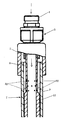
- the screw portion 1 of the upper connecting pipe 3 shown in the upper enlarged sectional view of FIG. 3 is screwed and fixed to a supply pipe (not shown) for supplying a gas-liquid mixed fluid of sodium hypochlorite water or hot water and carbon dioxide.
- the screw part 4 of the lower connecting pipe 6 shown in the lower enlarged sectional view of FIG. 4 is screwed and fixed to a discharge pipe (not shown) for discharging the generated carbonated spring.
- the discharge pipe (not shown) is provided with a faucet, shower, etc. at the tip. As shown in FIG.
- the gas-liquid mixed fluid of liquid sodium hypochlorite water or warm water and bubble carbon dioxide flows into the small diameter inner tube 8 through the fitting tube 2 of the upper connecting tube 3.
- the gas-liquid mixed fluid accumulated inside the container of the inner cylinder 11 is ejected from a large number of pores 12 formed in the small-diameter inner cylinder 8 and flows out into the space between the outer cylinder 7 and the inner cylinder 11 as a jet of fine bubbles.
- the gas-liquid mixed fluid is ejected from the pores 12, the liquid sodium hypochlorite water or warm water and the bubble carbon dioxide are stirred, and the carbon dioxide dissolves in the sodium hypochlorite water or warm water.
- the carbon dioxide-dissolved fluid that has flowed into the space between the outer cylinder 7 and the inner cylinder 11 flows downstream along the tapered surface 9 and flows out through the gap between the outer cylinder 7 and the large-diameter inner cylinder 10 as an annular jet fluid. As shown in FIG. 4, it flows down to the outside of the double cylinder 5 of the lower connection pipe 6, collides with the bottom 14 of the lower connection pipe 6 and rises backward, and doubles from the upper part of the double cylinder 5. It flows into the cylinder 5.
- the carbon dioxide dissolving fluid When colliding with the bottom portion 14 of the lower connecting pipe 6 and rising backward, the carbon dioxide dissolving fluid becomes a completely dissolved carbonated spring, and the bottom surface of the large-diameter inner pipe 10 and the upper surface of the lower connecting pipe 6 In between, it flows into the said double cylinder 5 from space.
- the generated carbonated spring is discharged from the double cylinder 5 through a flow path to a discharge pipe (not shown), and the carbonated spring is used through a faucet, a shower, and the like.
Landscapes
- Chemical & Material Sciences (AREA)
- Chemical Kinetics & Catalysis (AREA)
- Health & Medical Sciences (AREA)
- Dispersion Chemistry (AREA)
- Public Health (AREA)
- Pain & Pain Management (AREA)
- Epidemiology (AREA)
- Physical Education & Sports Medicine (AREA)
- Rehabilitation Therapy (AREA)
- Life Sciences & Earth Sciences (AREA)
- Animal Behavior & Ethology (AREA)
- General Health & Medical Sciences (AREA)
- Veterinary Medicine (AREA)
- Devices For Medical Bathing And Washing (AREA)
Applications Claiming Priority (2)
| Application Number | Priority Date | Filing Date | Title |
|---|---|---|---|
| JP2011-097106 | 2011-04-25 | ||
| JP2011097106A JP5650046B2 (ja) | 2011-04-25 | 2011-04-25 | 多目的ガス溶解装置 |
Publications (1)
| Publication Number | Publication Date |
|---|---|
| WO2012147459A1 true WO2012147459A1 (ja) | 2012-11-01 |
Family
ID=47071984
Family Applications (1)
| Application Number | Title | Priority Date | Filing Date |
|---|---|---|---|
| PCT/JP2012/058928 Ceased WO2012147459A1 (ja) | 2011-04-25 | 2012-04-02 | 多目的ガス溶解装置 |
Country Status (2)
| Country | Link |
|---|---|
| JP (1) | JP5650046B2 (enExample) |
| WO (1) | WO2012147459A1 (enExample) |
Families Citing this family (2)
| Publication number | Priority date | Publication date | Assignee | Title |
|---|---|---|---|---|
| KR101830276B1 (ko) * | 2016-08-03 | 2018-03-29 | 이십일세기이엔지 주식회사 | 양액재배용 산소용해장치 |
| JP6602284B2 (ja) * | 2016-11-25 | 2019-11-06 | 株式会社Shaft | ガス溶解器 |
Citations (4)
| Publication number | Priority date | Publication date | Assignee | Title |
|---|---|---|---|---|
| JPH01310726A (ja) * | 1989-04-28 | 1989-12-14 | Ise Kagaku Kogyo Kk | 流体の分散混合装置 |
| JP2000153142A (ja) * | 1998-11-24 | 2000-06-06 | Hikoroku Sugiura | 複数流体混合装置 |
| WO2005035102A1 (ja) * | 2003-10-10 | 2005-04-21 | Hikoroku Sugiura | 流体浄化方法及びスタティックミキサー |
| JP2006334556A (ja) * | 2005-06-06 | 2006-12-14 | Hitachi Housetec Co Ltd | 微細気泡発生ノズル、及び微細気泡発生浴槽 |
Family Cites Families (5)
| Publication number | Priority date | Publication date | Assignee | Title |
|---|---|---|---|---|
| JP2002018257A (ja) * | 2000-07-03 | 2002-01-22 | Hikoroku Sugiura | マイクロミキサー |
| JP2003126667A (ja) * | 2001-10-22 | 2003-05-07 | Mitsuru Kitahara | 空気混合供給装置 |
| JP2009078140A (ja) * | 2007-09-06 | 2009-04-16 | Shinwa:Kk | 身体ケア用洗浄水供給装置 |
| JP5170409B2 (ja) * | 2008-04-03 | 2013-03-27 | 国立大学法人 筑波大学 | 旋回流型マイクロバブル発生装置 |
| JP4916496B2 (ja) * | 2008-10-07 | 2012-04-11 | 株式会社リガルジョイント | 流体混合装置 |
-
2011
- 2011-04-25 JP JP2011097106A patent/JP5650046B2/ja not_active Expired - Fee Related
-
2012
- 2012-04-02 WO PCT/JP2012/058928 patent/WO2012147459A1/ja not_active Ceased
Patent Citations (4)
| Publication number | Priority date | Publication date | Assignee | Title |
|---|---|---|---|---|
| JPH01310726A (ja) * | 1989-04-28 | 1989-12-14 | Ise Kagaku Kogyo Kk | 流体の分散混合装置 |
| JP2000153142A (ja) * | 1998-11-24 | 2000-06-06 | Hikoroku Sugiura | 複数流体混合装置 |
| WO2005035102A1 (ja) * | 2003-10-10 | 2005-04-21 | Hikoroku Sugiura | 流体浄化方法及びスタティックミキサー |
| JP2006334556A (ja) * | 2005-06-06 | 2006-12-14 | Hitachi Housetec Co Ltd | 微細気泡発生ノズル、及び微細気泡発生浴槽 |
Also Published As
| Publication number | Publication date |
|---|---|
| JP5650046B2 (ja) | 2015-01-07 |
| JP2012228637A (ja) | 2012-11-22 |
Similar Documents
| Publication | Publication Date | Title |
|---|---|---|
| US9475011B2 (en) | Microbubble therapy method and generating apparatus | |
| JP4925310B2 (ja) | シャワー装置 | |
| JP6768356B2 (ja) | 吐水設備構造及び同吐水設備構造を備えたシャワーヘッド、蛇口水道設備、打たせ湯設備 | |
| EP2226055B1 (en) | Microbubble generating apparatus | |
| KR101088145B1 (ko) | 절수형 미세기포 생성장치 | |
| JP5650046B2 (ja) | 多目的ガス溶解装置 | |
| KR20080092750A (ko) | 욕조용 산소 마이크로버블 공급장치 | |
| CN107073198B (zh) | 大肠清洗器 | |
| JP4360501B1 (ja) | オゾン水生成装置及びオゾン水生成方法 | |
| KR102139574B1 (ko) | 마이크로버블 및 초음파 발생이 가능한 욕조 | |
| KR101980535B1 (ko) | 향 첨가 마이크로버블 살균수 제조장치 | |
| JP4360502B1 (ja) | オゾン水生成装置 | |
| JP6624672B2 (ja) | 浴室用の超微細気泡発生装置 | |
| JP3131528U (ja) | 水流ポンプ及びそれを設備した洗浄器具 | |
| CN103521103A (zh) | 一种气泡发生器 | |
| KR101910632B1 (ko) | 수소수 제조장치 | |
| JP5938794B2 (ja) | 微細気泡発生装置 | |
| JP4710517B2 (ja) | シャワー装置 | |
| JP2010162149A (ja) | 浴槽用微小気泡発生装置および浴槽用微小気泡発生方法 | |
| KR102675068B1 (ko) | 나노버블발생용 용해장치 | |
| KR102586466B1 (ko) | 나노버블발생용 용해장치 | |
| CN203540355U (zh) | 一种气泡发生器 | |
| CN111115787B (zh) | 一种制备高浓度碳酸泉的融合装置 | |
| JP2008018130A (ja) | 浴槽サウナ装置 | |
| TWM551182U (zh) | 水素射流裝置 |
Legal Events
| Date | Code | Title | Description |
|---|---|---|---|
| 121 | Ep: the epo has been informed by wipo that ep was designated in this application |
Ref document number: 12777218 Country of ref document: EP Kind code of ref document: A1 |
|
| NENP | Non-entry into the national phase |
Ref country code: DE |
|
| 122 | Ep: pct application non-entry in european phase |
Ref document number: 12777218 Country of ref document: EP Kind code of ref document: A1 |