WO2012147344A1 - Dispositif de décodage vidéo, procédé de décodage vidéo, et programme de décodage vidéo - Google Patents
Dispositif de décodage vidéo, procédé de décodage vidéo, et programme de décodage vidéo Download PDFInfo
- Publication number
- WO2012147344A1 WO2012147344A1 PCT/JP2012/002840 JP2012002840W WO2012147344A1 WO 2012147344 A1 WO2012147344 A1 WO 2012147344A1 JP 2012002840 W JP2012002840 W JP 2012002840W WO 2012147344 A1 WO2012147344 A1 WO 2012147344A1
- Authority
- WO
- WIPO (PCT)
- Prior art keywords
- block
- motion vector
- motion
- prediction
- unit
- Prior art date
Links
Images


Classifications
-
- H—ELECTRICITY
- H04—ELECTRIC COMMUNICATION TECHNIQUE
- H04N—PICTORIAL COMMUNICATION, e.g. TELEVISION
- H04N19/00—Methods or arrangements for coding, decoding, compressing or decompressing digital video signals
- H04N19/10—Methods or arrangements for coding, decoding, compressing or decompressing digital video signals using adaptive coding
- H04N19/102—Methods or arrangements for coding, decoding, compressing or decompressing digital video signals using adaptive coding characterised by the element, parameter or selection affected or controlled by the adaptive coding
- H04N19/103—Selection of coding mode or of prediction mode
- H04N19/105—Selection of the reference unit for prediction within a chosen coding or prediction mode, e.g. adaptive choice of position and number of pixels used for prediction
-
- H—ELECTRICITY
- H04—ELECTRIC COMMUNICATION TECHNIQUE
- H04N—PICTORIAL COMMUNICATION, e.g. TELEVISION
- H04N19/00—Methods or arrangements for coding, decoding, compressing or decompressing digital video signals
- H04N19/50—Methods or arrangements for coding, decoding, compressing or decompressing digital video signals using predictive coding
- H04N19/503—Methods or arrangements for coding, decoding, compressing or decompressing digital video signals using predictive coding involving temporal prediction
- H04N19/51—Motion estimation or motion compensation
- H04N19/513—Processing of motion vectors
- H04N19/517—Processing of motion vectors by encoding
- H04N19/52—Processing of motion vectors by encoding by predictive encoding
-
- H—ELECTRICITY
- H04—ELECTRIC COMMUNICATION TECHNIQUE
- H04N—PICTORIAL COMMUNICATION, e.g. TELEVISION
- H04N19/00—Methods or arrangements for coding, decoding, compressing or decompressing digital video signals
- H04N19/10—Methods or arrangements for coding, decoding, compressing or decompressing digital video signals using adaptive coding
- H04N19/169—Methods or arrangements for coding, decoding, compressing or decompressing digital video signals using adaptive coding characterised by the coding unit, i.e. the structural portion or semantic portion of the video signal being the object or the subject of the adaptive coding
- H04N19/17—Methods or arrangements for coding, decoding, compressing or decompressing digital video signals using adaptive coding characterised by the coding unit, i.e. the structural portion or semantic portion of the video signal being the object or the subject of the adaptive coding the unit being an image region, e.g. an object
- H04N19/176—Methods or arrangements for coding, decoding, compressing or decompressing digital video signals using adaptive coding characterised by the coding unit, i.e. the structural portion or semantic portion of the video signal being the object or the subject of the adaptive coding the unit being an image region, e.g. an object the region being a block, e.g. a macroblock
-
- H—ELECTRICITY
- H04—ELECTRIC COMMUNICATION TECHNIQUE
- H04N—PICTORIAL COMMUNICATION, e.g. TELEVISION
- H04N19/00—Methods or arrangements for coding, decoding, compressing or decompressing digital video signals
- H04N19/50—Methods or arrangements for coding, decoding, compressing or decompressing digital video signals using predictive coding
- H04N19/503—Methods or arrangements for coding, decoding, compressing or decompressing digital video signals using predictive coding involving temporal prediction
- H04N19/51—Motion estimation or motion compensation
- H04N19/577—Motion compensation with bidirectional frame interpolation, i.e. using B-pictures
-
- H—ELECTRICITY
- H04—ELECTRIC COMMUNICATION TECHNIQUE
- H04N—PICTORIAL COMMUNICATION, e.g. TELEVISION
- H04N19/00—Methods or arrangements for coding, decoding, compressing or decompressing digital video signals
- H04N19/50—Methods or arrangements for coding, decoding, compressing or decompressing digital video signals using predictive coding
- H04N19/593—Methods or arrangements for coding, decoding, compressing or decompressing digital video signals using predictive coding involving spatial prediction techniques
Definitions
- the present invention relates to a video decoding technique using motion compensated prediction, and more particularly to a technique for deriving a motion vector used in motion compensated prediction.
- motion compensated prediction is generally used to increase compression efficiency by utilizing temporal correlation between pictures.
- motion compensation prediction a prediction value is obtained from a reference picture in consideration of the direction and amount of motion indicated by a motion vector. By encoding the difference value between the prediction value obtained by motion compensation prediction and the pixel value of the encoding target picture, redundancy can be removed and compression efficiency can be increased.
- one picture can be I picture for intra-picture coding, P picture capable of unidirectional motion compensation prediction, unidirectional or bidirectional motion compensation prediction Encoded as a B picture.
- a prediction motion vector is derived from the neighboring blocks. Then, a differential motion vector between the motion vector of the encoding target block and the predicted motion vector is calculated, and the differential motion vector is entropy encoded.
- the reason why the motion vector predictor is derived from the peripheral block is that the motion vector of the encoding target block is considered to have a correlation with the motion vector of the peripheral block. In entropy coding, this correlation is used to perform compression so that the motion vector compression efficiency increases as the absolute value of the difference motion vector decreases.
- Patent Document 1 discloses a motion vector prediction method using peripheral blocks of an encoding target block.
- the prediction motion vector is derived for each prediction direction such as forward and backward, the motion of an object having a temporal correlation different from the motion of the block to be encoded is a neighboring block. If it exists in the block, a motion vector predictor unrelated to the original motion of the object in the encoding target block is derived, and the compression efficiency of the motion vector may not be improved.
- the present invention has been made in view of such a situation, and an object of the present invention is to provide a motion that can improve the accuracy of motion vector derivation on the decoding side while improving the compression efficiency of the motion vector on the encoding side. It is to provide a vector encoding technique and a motion vector decoding technique.
- a moving picture decoding apparatus is a moving picture decoding apparatus that decodes a code string encoded using motion compensated prediction in units of blocks obtained by dividing each picture of a moving picture.
- the motion information deriving unit (550) has the same number of motion vectors as the first block and the number of motion vectors as the second block, and a reference index indicating a reference picture to which the motion vector of the first block refers. Whether or not the second block is a candidate block is determined based on whether or not the reference index indicating the reference picture referred to by the motion vector of the second block is the same.
- Still another aspect of the present invention is a moving picture decoding method.
- This method is a moving picture decoding method for decoding a code string encoded using motion compensated prediction in units of blocks obtained by dividing each picture of a moving picture, and a motion vector of a decoding target prediction block is calculated as the decoding target.
- a motion information deriving step derived based on a motion vector of any candidate block of candidate blocks selected from neighboring blocks of the prediction block, and motion compensated prediction using the motion vector derived by the motion information deriving step
- the number of motion vectors of the first block and the number of motion vectors of the second block are the same, and a reference index indicating a reference picture referenced by the motion vector of the first block and the first block Whether or not the second block is a candidate block is determined based on whether or not the reference indexes indicating the reference pictures referenced by the motion vectors of the two blocks are the same.
- the present invention by considering the motion vectors of the peripheral blocks, it is possible to improve the accuracy of motion vector derivation while improving the compression efficiency of motion vectors on the encoding side.
- FIG. 5 is a diagram illustrating a detailed configuration of a motion vector number acquisition unit and a motion vector encoding unit in FIG. 4. It is a flowchart explaining the detail of the derivation
- the MPEG-2 video (ISO / IEC 13818-2) encoding system was established as a general-purpose video compression encoding system, and the digital VTR of DVD (Digital Versatile Disk) and D-VHS (registered trademark) standards. Is widely used as an application for storage media such as magnetic tape and digital broadcasting.
- motion compensation prediction In these encoding methods, motion compensation prediction is used.
- motion compensation prediction a prediction value is obtained from a reference picture in consideration of the direction and amount of motion indicated by a motion vector. By encoding the difference value between the prediction value obtained by motion compensation prediction and the pixel value of the encoding target picture, redundancy can be removed and compression efficiency can be increased.
- ⁇ ⁇ ⁇ ⁇ Pictures are divided into three types depending on how motion compensated prediction is used. These are an I picture that does not use motion compensated prediction, a P picture that can perform unidirectional motion compensated prediction, and a B picture that can perform unidirectional or bidirectional motion compensated prediction.
- motion compensation prediction is performed in units of macroblocks using the immediately preceding I picture or P picture in the display order as a reference picture.
- MPEG-4 AVC a plurality of encoded pictures can be used as reference pictures, and motion compensation prediction is performed by selecting an optimum picture for each prediction block (described later). Can do.
- any reference picture can be used for motion compensation prediction regardless of the forward or backward direction, regardless of the restriction of one front and one rear in the display order.
- a B picture can be referred to as a reference picture.
- the decoded picture is stored in the reference frame memory and managed.
- a reference picture is specified by arranging pictures stored in a reference frame memory in a predetermined method to create a reference picture list and describing the index in the encoded stream.
- the “reference picture list” is a list in which reference pictures in a reference frame used in motion compensation prediction can be rearranged. Coding efficiency can be improved by rearranging the reference pictures according to the frequency of use using the reference picture list.
- the reference picture list can be rearranged by sending reference picture list change information in a slice header added for each slice.
- an encoded picture registered in the reference picture list is used as a reference picture for each prediction block, and a predicted value is calculated from the reference picture in consideration of the direction and amount of motion indicated by the motion vector. Is calculated.
- the reference picture list is prepared in two directions. In general, a reference picture list L0 for registering a temporally forward-coded picture of an encoding target picture and, in general, a temporally backward-encoded picture of a encoding target picture is registered. Reference picture list L1. The P picture uses the reference picture list L0, and the B picture uses the reference picture list L0 and the reference picture list L1.
- the direction of motion compensated prediction by the reference picture list L0 is direction 0, and the direction of motion compensated prediction by the reference picture list L1 is direction 1.
- a picture is divided into units of macro blocks (hereinafter referred to as MB) of 16 horizontal pixels ⁇ vertical 16 pixels, and the MB is further divided into 16 horizontal pixels ⁇ 16 vertical pixels, 16 horizontal pixels ⁇ 8 vertical pixels,
- the prediction block is divided into any of prediction blocks of horizontal 8 pixels ⁇ vertical 16 pixels, horizontal 8 pixels ⁇ vertical 8 pixels, horizontal 8 pixels ⁇ vertical 4 pixels, horizontal 4 pixels ⁇ vertical 8 pixels, and horizontal 4 pixels ⁇ vertical 4 pixels.
- a motion vector indicating the motion direction and the motion amount and a reference index indicating a reference picture in the reference picture list are assigned to each prediction block of the P picture.
- One or two motion vectors indicating a motion direction and a motion amount and a reference index indicating a reference picture in a reference picture list are assigned to a prediction block of a B picture.
- a pixel value of a reference picture indicated by the motion vector and the reference index is a prediction value.
- a prediction block (hereinafter referred to as bi-directional prediction) in which two motion vectors and two reference indexes are assigned, an average value of pixel values of reference pictures indicated by the respective motion vectors and reference indexes is a predicted value.
- a block indicates a prediction block.
- block A, block B, and block C that are peripheral blocks of the encoding target block X are determined (step S5000).
- the reference index in the direction 0 of the block A is defined as refIdxL0A
- the motion vector in the direction 0 is defined as mvL0A
- the reference index in the direction 1 is defined as refIdxL1A
- the motion vector in the direction 1 is defined as mvL1A.
- refIdxL0B, mvL0B, refIdxL1B, mvL1B of block B and refIdxL0C, mvL0C, refIdxL1C, mvL1C of block C are defined.
- step S5010 It is checked whether or not motion compensation prediction in the direction 0 is performed in the encoding target block X (step S5010).
- step S5010 When motion compensation prediction in the direction 0 is not performed (NO in step S5010), the reference index refIdxL0X in the direction 0 of the encoding target block X is set to ⁇ 1, and the motion vector mvL0X is set to (0, 0) (step S5030). .
- step S5010 When motion compensation prediction in the direction 0 is performed (YES in step S5010), only one of the three peripheral blocks A, B, and C in the reference index refIdxL0A, refIdxL0B, and refIdxL0C in the direction 0 is encoded. It is checked whether it is the same as refIdxL0X, which is the reference index of the target block X (step S5020). If there is only one peripheral block whose reference index matches the encoding target block X (YES in step S5020), The motion vector mvL0N of the peripheral block N is set as the predicted motion vector mvpL0X of the encoding target block X (step S5040).
- mvpL0X (x) Media [mvL0A (x), mvL0B (x), mvL0C (x)]
- mvpL0X (y) Media [mvL0A (y), mvL0B (y), mvL0C (y)] (Formula 1)
- step S5110 to S5150 the same processing as in direction 0 is performed for motion compensated prediction in direction 1 (steps S5110 to S5150).
- a predicted motion vector is prevented from taking an unexpected value by using a median filter.
- the median filter has a problem that the most efficient motion vector cannot be used as a predicted value.
- the motion vector of the peripheral block is present. Has been introduced as a predicted motion vector.
- the motion of the object has a correlation in the time direction.
- whether or not the reference indexes of the encoding target block and the neighboring blocks match is independently verified for each prediction direction, and therefore, the temporal correlation different from the motion of the encoding target block.
- there is a motion of an object having a symbol in a peripheral block there is a problem that the original motion of the encoding target block cannot be predicted correctly.
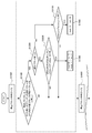
- the positional relationship of the peripheral block A, block B, and block C with respect to the encoding target block X of the encoding target picture is as illustrated. Since the same object exists in the encoding target block X and the block B, bi-directional prediction using the forward reference picture P0 and the backward reference picture P1 is used for the encoding target block X and the block B. On the other hand, the object including the block C has a strong correlation with the forward reference picture P0 and unidirectional prediction is used, and the object including the block A has a strong correlation with the backward reference picture P1 and uses the unidirectional prediction.
- the encoding target block X performs motion compensation prediction with a motion vector ( ⁇ 8, 8) for the reference picture P0, and motion compensation prediction with a motion vector (8, ⁇ 8) for the reference picture P1. I do.
- the block A performs motion compensation prediction with a motion vector (0, 0) with respect to the reference picture P1.
- the block B performs motion compensation prediction with a motion vector of ( ⁇ 8, 8) for the reference picture P0, and performs motion compensation prediction with a motion vector of (8, ⁇ 8) for the reference picture P1.
- Block C performs motion compensation prediction with a motion vector of (0, 0) with respect to reference picture P0.
- the reference index “0” in the direction 0 indicates the reference picture P0
- the reference index “0” in the direction 1 indicates the reference picture P1.
- the reference index refIdxL0X in the direction 0 of the encoding target block X is 0, the motion vector mvL0X is ( ⁇ 8, 8), the reference index refIdxL1X in the direction 1 is 0, and the motion vector mvL1B is (8, ⁇ 8).
- the reference index refIdxL0A in the direction 0 of the peripheral block A is -1, the motion vector mvL0A is (0, 0), the reference index refIdxL1A in the direction 1 is 0, and the motion vector mvL1A is (0, 0).
- the reference index refIdxL0B in the direction 0 of the peripheral block B is 0, the motion vector mvL0B is ( ⁇ 8, 8), the reference index refIdxL1B in the direction 1 is 0, and the motion vector mvL1B is (8, ⁇ 8).
- the reference index refIdxL0C in the direction 0 of the peripheral block C is 0, the motion vector mvL0C is (0, 0), the reference index refIdxL1C in the direction 1 is -1, and the motion vector mvL1C is (0, 0).
- refIdxL0A is -1
- mvL0A is (0, 0)
- refIdxL1C is -1
- mvL1C is (0, 0) because block A and block C are unidirectionally predicted.
- the difference motion vector dmvL0X becomes ( ⁇ 8, 8) by calculating the difference between the motion vector mvL0X of the encoding target block X and the predicted motion vector mvpL0X as shown in Equation 3.
- the predicted motion vector mvpL1X is calculated by calculating the median value of each component of the motion vectors mvL1A, mvL1B, mvL1C in the direction 1 of the peripheral blocks A, B, C as shown in Equation 4, and (0, 0) and Become.
- the difference motion vector dmvL1X is (8, ⁇ 8).
- the encoding target block X that is bi-directionally predicted has a high correlation with the only peripheral block B that is bi-predicted in the same manner, but the reference index is independently determined for each prediction direction.
- the identity is determined, there are peripheral blocks having the same reference index in addition to the peripheral block B. Therefore, in the conventional motion vector prediction method, the predicted motion vector is obtained from the intermediate values of all the neighboring blocks for each prediction direction, and an accurate predicted motion vector cannot be obtained, and the motion vector of the encoding target block Cannot be encoded with reduced redundancy.
- FIG. 4 is a diagram illustrating a configuration of a moving image encoding apparatus using the motion vector prediction method according to the first embodiment.
- the moving image coding apparatus includes a subtraction unit 100, a prediction error coding unit 110, a code string generation unit 120, a prediction error decoding unit 130, an addition unit 140, a motion compensation prediction method determination unit 150, a frame memory 160, a motion vector coding. Unit 170, motion information storage unit 180, and motion vector number acquisition unit 190.
- Encoding is performed in units of macro blocks.
- the input picture 10 is divided into macroblock units and supplied to the subtraction unit 100 and the motion compensation prediction method determination unit 150.
- the motion compensation prediction method determination unit 150 detects a motion vector for each reference picture from the encoding target macroblock and the reference picture supplied from the frame memory 160 by a technique such as block matching, and the rate is determined from the detected motion vectors.
- a prediction picture is generated by determining an optimal motion compensation prediction method by a distortion optimization method or the like.
- the motion compensation prediction method determination unit 150 supplies the prediction picture generated from the determined motion compensation prediction method to the subtraction unit 100 and the addition unit 140. In addition, the motion compensation prediction method determination unit 150 sends a reference index and a motion vector corresponding to the determined motion compensation prediction method to the motion information storage unit 180.
- the determination of the motion compensation prediction method refers to a method for dividing a prediction block in a macroblock, a method for predicting a divided prediction block (unidirectional prediction / bidirectional prediction), and a reference picture (reference index) in each prediction direction. Is to decide.
- the subtraction unit 100 obtains a prediction error based on the difference between the encoding target macroblock and the prediction picture supplied from the motion compensation prediction method determination unit 150, and supplies the prediction error to the prediction error encoding unit 110.
- the prediction error encoding unit 110 performs processing such as orthogonal transformation and quantization on the prediction error supplied from the subtraction unit 100 to convert it into prediction error code data, and a code string generation unit 120 and a prediction error decoding unit 130. To supply.
- the prediction error decoding unit 130 performs processing such as inverse quantization and inverse orthogonal transform on the prediction error code data supplied from the prediction error encoding unit 110 to convert the prediction error into prediction error, and sends the prediction error to the addition unit 140. Supply.
- the adding unit 140 obtains a decoded picture by adding the prediction error supplied from the prediction error decoding unit 130 and the prediction picture supplied from the motion compensation prediction method determining unit 150, and supplies the decoded picture to the frame memory 160.
- the frame memory 160 holds the decoded picture supplied from the adding unit 140 as a reference picture and supplies it to the motion compensation prediction method determining unit 150.
- the motion information storage unit 180 stores the motion vector and the reference index supplied from the motion compensation prediction method determination unit 150, and supplies the motion vector to the motion vector encoding unit 170.
- the motion information storage unit 180 stores motion vectors and reference indexes for all macroblocks of the input picture, and supplies the motion vectors and reference indexes of neighboring macroblocks of the encoding target macroblock to the motion vector encoding unit 170. To do.
- the motion information storage unit 180 stores the motion vectors and reference indexes for all the macroblocks of the input picture, but the purpose of the motion information storage unit 180 is to store the encoding target macroblock. This is to supply the motion vectors and reference indexes of the peripheral blocks to the motion vector encoding unit 170, and if it can be realized, it is not necessary to store the motion vectors and reference indexes for all macroblocks of the input picture. It is only necessary to memorize as much as possible.
- the motion vector encoding unit 170 is supplied from the motion vector and reference index of the encoding target macroblock supplied from the motion information storage unit 180, the motion vector and reference index of the neighboring macroblock, and the motion vector number acquisition unit 190. Determine the motion vector predictor from the number of motion vectors of the encoding target macroblock and neighboring macroblocks, determine the difference motion vector from the motion vector of the encoding target macroblock and the prediction motion vector, convert it to differential motion vector code data, and code string It supplies to the production
- the code sequence generation unit 120 converts the prediction error code data supplied from the prediction error encoding unit 110 and the differential motion vector code data supplied from the motion vector encoding unit 170 into an output code sequence together with other control information. And output.
- the motion vector number acquisition unit 190 acquires the number of motion vectors for each macroblock from the motion information storage unit 180, and supplies the motion vector number of the encoding target macroblock and the surrounding macroblocks to the motion vector encoding unit 170.
- FIG. 5 is a diagram illustrating a detailed configuration of the motion vector number acquisition unit 190 and the motion vector encoding unit 170 in FIG.
- the motion vector number acquisition unit 190 includes an encoding target block motion vector number acquisition unit 210, a peripheral block motion vector number acquisition unit 220, and a peripheral block identification unit 230.
- the motion vector encoding unit 170 includes a predicted motion vector deriving unit 240, a differential motion vector calculating unit 250, and a differential motion vector encoding unit 260.
- the encoding target block motion vector number acquisition unit 210 acquires the number of motion vectors of the encoding target block from the motion information storage unit 180.
- the peripheral block specifying unit 230 refers to the motion information storage unit 180 and specifies a plurality of encoded peripheral blocks around the encoding target block.
- the peripheral block motion vector number acquisition unit 220 acquires the number of motion vectors of each specified peripheral block from the motion information storage unit 180.
- the motion vector predictor deriving unit 240 receives information on the reference indexes and motion vectors of a plurality of neighboring blocks from the neighboring block specifying unit 230, and obtains the number of motion vectors of the coding target block from the coding target block motion vector number obtaining unit 210.
- the number of motion vectors of peripheral blocks is received from the peripheral block motion vector number acquisition unit 220.
- the prediction motion vector deriving unit 240 identifies a peripheral block as a prediction candidate block when there is only one peripheral block having the same number of motion vectors as the number of motion vectors of the encoding target block among a plurality of peripheral blocks. Then, the motion vector of the prediction candidate block is supplied to the differential motion vector calculation unit 250 as the predicted motion vector MVP.
- the difference motion vector calculation unit 250 calculates a difference motion vector MVD based on the difference between the motion vector MV of the encoding target block read from the motion information storage unit 180 and the prediction motion vector MVP received from the prediction motion vector derivation unit 240. And supplied to the differential motion vector encoding unit 260.
- the differential motion vector encoding unit encodes the differential motion vector MVD and supplies it to the code string generation unit 120.
- the prediction motion vector is derived for each prediction block in the encoding target macroblock.
- the first prediction motion vector derivation process is performed in the previous stage, and then the second prediction motion vector derivation process is performed in the subsequent stage.
- the second predictive motion vector derivation process is the same as the conventional predictive motion vector derivation method described in FIG.
- the peripheral block specifying unit 230 determines block A, block B, and block C that are peripheral blocks of the encoding target block X as shown in FIG. 1A (step S1000).
- the peripheral block motion vector number acquisition unit 220 acquires the number of motion vectors of block A, which is a peripheral block, the number of motion vectors of block B, and the number of motion vectors of block C, and the predicted motion vector derivation unit 240 It is checked whether or not there is only one peripheral block N having the same number of motion vectors as that of the encoding target block X among the blocks A, B, and C (step S1100).
- the motion vector predictor deriving unit 240 identifies the peripheral block as a prediction candidate block, and It is checked whether or not the number of motion vectors in block X is 2 (step S1200).
- the motion vector in the single prediction direction Z (forward L0 or backward L1) is set as the predicted motion vector of the encoding target block X (step S1400).
- the single prediction direction Z is a direction in which a motion vector exists.
- the second prediction As the motion vector deriving process, the conventional processes after step 5000 are performed.
- peripheral blocks A, B, and C were at the positions shown in FIG. 1A, but the peripheral blocks are limited to the positions shown in FIG. Instead, any position may be used as long as it is an encoded block.
- the number of peripheral blocks is not necessarily three, but may be two or more.
- the peripheral block is not only a block in the same picture that is spatially adjacent to the current block, but also a reference picture that is encoded immediately before it is temporally adjacent to the current block. It may be a block at the same position as the block or a block adjacent thereto.
- the process after step 5000 is performed as the second predicted motion vector derivation process, but the process is not limited to the process after step 5000.
- the motion vector of any one of a plurality of peripheral blocks having the same number of motion vectors as the encoding target block X May be used as a predicted motion vector, or a weighted average of motion vectors of a plurality of peripheral blocks having the same number of motion vectors as the encoding target block X may be obtained and used as a predicted motion vector.
- the motion vector of any one of the neighboring blocks may be used as a predicted motion vector, and the motion vectors of a plurality of neighboring blocks may be used.
- a weighted average may be obtained and used as a predicted motion vector.
- the prediction motion vector derivation method of the first embodiment is applied to the specific example described in FIG. Since the only peripheral block having the same number of motion vectors as the number of motion vectors 2 of the encoding target block X is the block B, the predicted motion vectors mvpL0X and mvpL1X of the encoding target block X are expressed by ( ⁇ 8 , 8) and (8, -8).
- the differential motion vectors dmvL0X and dmvL1X are (0, 0) and (0, 0) from Equation 9, respectively.
- the motion vector of the peripheral block having the same number of motion vectors as the number of motion vectors of the encoding target block is used as the prediction motion vector. Even if the motion of an object having a temporal correlation different from the motion of the encoding target block exists in the neighboring blocks, the motion vector redundancy of the encoding target block is derived by deriving the predicted motion vector according to the original motion. Can be encoded.
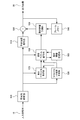
- FIG. 7 is a diagram illustrating a configuration of a moving image decoding apparatus using the motion vector prediction method according to the first embodiment.
- the video decoding apparatus includes a code string analysis unit 500, a prediction error decoding unit 510, an addition unit 520, a motion compensation prediction unit 530, a frame memory 540, a motion vector decoding unit 550, a motion information storage unit 560, and a motion vector number acquisition unit. 570.
- Decoding is performed in units of macroblocks.
- the input code string 10 is supplied to the code string analysis unit 500.
- the code string analysis unit 500 decodes and acquires the prediction error encoded data, the difference motion vector, the reference index, and the macroblock type from the input code string 10.
- the code string analysis unit 500 provides the prediction error encoded data to the prediction error decoding unit 510, the difference motion vector and the reference index to the motion vector decoding unit 550, and the macroblock type to the motion vector number acquisition unit 570 in units of prediction blocks. Supply.
- the subsequent processing is repeated four times within the macro block.
- the prediction error decoding unit 510 converts the prediction error encoded data supplied from the code string analysis unit 500 into a prediction error by performing processing such as inverse quantization and inverse orthogonal transform, and supplies the prediction error to the addition unit 520. .
- the motion vector decoding unit 550 includes the difference motion vector and reference index of the decoding target macroblock supplied from the code string analysis unit 500, and the number of motion vectors of the decoding target macroblock and neighboring macroblocks supplied from the motion vector number acquisition unit 570. Then, a motion vector is obtained from the motion vector and the reference index of the neighboring macroblock supplied from the motion information storage unit 560, and a motion vector is decoded from the difference motion vector and the motion vector predictor of the decoding target macroblock. The vector and the reference index are supplied to the motion compensation prediction unit 530 and also supplied to the motion information storage unit 560. A detailed motion vector decoding method will be described later.
- the motion information storage unit 560 stores the motion vector and reference index supplied from the motion vector decoding unit 550, and supplies the stored motion vector and reference index to the motion vector decoding unit 550 as necessary.
- the motion vector number acquisition unit 570 acquires the number of motion vectors for each macroblock from the macroblock type supplied from the code stream analysis unit 500, and calculates the number of motion vectors of the decoding target macroblock and the surrounding macroblocks as the motion vector decoding unit 550. To supply.
- the acquisition of the number of motion vectors can be determined from the number of differential motion vectors and the number of reference indexes in addition to the acquisition from the macroblock type.
- the motion compensated prediction unit 530 generates a prediction value using the motion vector and reference index supplied from the motion vector decoding unit 550 and the reference picture supplied from the frame memory 540, and supplies the prediction value to the addition unit 520.
- the addition unit 520 generates a decoded value by adding the prediction error supplied from the prediction error decoding unit 510 and the prediction value supplied from the motion compensation prediction unit 530, supplies the decoded value to the frame memory 540, and as an image output 60 Output.
- the frame memory 540 stores the decoded picture supplied from the adding unit 520, and supplies the stored decoded picture as a reference picture to the motion compensation prediction unit 530 as necessary.
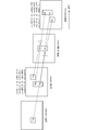
- FIG. 8 is a diagram illustrating the detailed configuration of the motion vector number acquisition unit 570 and the motion vector decoding unit 550 of FIG.
- the motion vector number acquisition unit 570 includes a decoding target block motion vector number acquisition unit 610, a peripheral block motion vector number acquisition unit 620, and a peripheral block identification unit 630.
- the motion vector decoding unit 550 includes a predicted motion vector deriving unit 640 and a motion vector calculating unit 650.
- the decoding target block motion vector number acquisition unit 610 acquires the number of motion vectors of the decoding target block from the code string analysis unit 500.
- the peripheral block specifying unit 230 refers to the motion information storage unit 560 and specifies a plurality of decoded peripheral blocks around the decoding target block.
- the peripheral block motion vector number acquisition unit 620 acquires the number of motion vectors of each specified peripheral block from the motion information storage unit 560.
- the motion vector predictor deriving unit 640 receives information on reference indexes and motion vectors of a plurality of neighboring blocks from the neighboring block specifying unit 630, and obtains the number of motion vectors of the decoding target block from the decoding target block motion vector number obtaining unit 610.
- the number of motion vectors of surrounding blocks is received from the motion vector number acquisition unit 620.
- the predicted motion vector deriving unit 640 specifies, as a prediction candidate block, when there is only one peripheral block having the same number of motion vectors as the number of motion vectors of the decoding target block among the plurality of peripheral blocks. Then, the motion vector of the prediction candidate block is supplied to the motion vector calculation unit 650 as a predicted motion vector MVP.
- the motion vector calculation unit 650 calculates the motion vector MV by adding the difference motion vector MVD of the decoding target block received from the code string analysis unit 500 and the prediction motion vector MVP received from the prediction motion vector derivation unit 640. And supplied to the motion compensation prediction unit 530.
- the method of deriving a predicted motion vector by the moving picture decoding apparatus according to the first embodiment is based on the moving picture coding apparatus according to the first embodiment if “the encoding target block” is read as “the decoding target block”. Since it is the same as the method of deriving the predicted motion vector, detailed description is omitted.
- FIG. 9 is a diagram illustrating a configuration of a moving image encoding apparatus using the motion vector prediction method according to the second embodiment.
- the moving image coding apparatus includes a subtraction unit 100, a prediction error coding unit 110, a code string generation unit 120, a prediction error decoding unit 130, an addition unit 140, a motion compensation prediction method determination unit 150, a frame memory 160, a motion vector coding.
- Unit 170, motion information storage unit 180, motion vector number acquisition unit 190, and macroblock boundary determination unit 200 is a subtraction unit 100, a prediction error coding unit 110, a code string generation unit 120, a prediction error decoding unit 130, an addition unit 140, a motion compensation prediction method determination unit 150, a frame memory 160, a motion vector coding.
- Unit 170 motion information storage unit 180, motion vector number acquisition unit 190, and macroblock boundary determination unit 200.
- Subtraction unit 100, prediction error encoding unit 110, code sequence generation unit 120, prediction error decoding unit 130, addition unit 140, motion compensation prediction method determination unit 150, frame memory 160, motion information storage unit of the second embodiment 180 and the motion vector number acquisition unit 190 have the same configurations as those of the first embodiment.
- a motion vector encoding unit 170 and a macroblock boundary determination unit 200 different from those in the first embodiment will be described with reference to FIGS. 9 and 10.
- the macroblock boundary determining unit 200 determines whether or not the encoding target block touches the macroblock boundary. If the encoding target block touches the macroblock boundary, the macroblock boundary flag is set to 1, and the encoding target block is a macro. When the block boundary is not touched, the macroblock boundary flag is set to 0 and the macroblock boundary flag is supplied to the motion vector encoding unit 170.
- Whether or not it touches the macroblock boundary can be determined using, for example, a prediction block number.
- the prediction block number will be described later.
- the motion vector encoding unit 170 is supplied from the motion information storage unit 180, the motion vector and reference index of the encoding target macroblock, the motion vector and reference index of the surrounding macroblock, and the motion supplied from the motion vector number acquisition unit 190.
- a prediction motion vector is obtained from the number of vectors and the macroblock boundary flag supplied from the macroblock boundary determination unit 200, and a difference motion vector is obtained from the motion vector of the encoding target macroblock and the prediction motion vector to obtain difference motion vector code data.
- the data is converted and supplied to the code string generation unit 120.
- the peripheral block specifying unit 230 determines block A, block B, block C, and block D, which are peripheral blocks of the encoding target block X, as shown in FIG. 1B (step S2000).
- the macroblock boundary determination unit 200 checks the value of the macroblock boundary flag (step S2100).
- the peripheral block motion vector number acquisition unit 220 acquires the number of motion vectors of the block A, block B, block C, and block D, which are peripheral blocks.
- the predicted motion vector deriving unit 240 checks whether or not there is only one peripheral block N having the same number of motion vectors as the number of motion vectors of the encoding target block X among the peripheral blocks A, B, C, and D. (Step S2200). After step S2200, the processing after step S1200 of the first embodiment is performed.
- step S5000 the process after step S5000 is performed as the second motion vector predictor derivation process as described in the first embodiment.
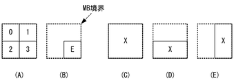
- FIG. 11A shows the prediction block number when the macroblock is divided into four 8 ⁇ 8 prediction blocks.
- FIG. 11B there is a block E with a prediction block number of 3 that does not touch the macroblock boundary.
- the block E includes the same object as the other blocks in the macro block and exhibits the same movement, the block E has one block X as shown in FIG. 11C, FIG. 11D, or FIG. Are likely to be encoded. Therefore, when the block E exists as an independent prediction block, it is unlikely that the block E and other blocks in the macro block include the same object and exhibit the same motion. Therefore, in such a case, it is desirable to proceed to the second predicted motion vector derivation process without intentionally performing the determination based on the number of motion vectors, whereby sudden motion vectors can be eliminated.
- the condition that it does not touch the macroblock boundary is that “the peripheral block is in the same macroblock. In other words.
- the encoding target block when the encoding target block is in contact with the macroblock boundary, the encoding target block is considered in consideration of the number of motion vectors of the encoding target block and the number of motion vectors of the surrounding blocks.
- the number of motion vectors of the current block and the number of motion vectors of the neighboring blocks are not taken into consideration, thereby reducing false detection of predicted motion vectors and predicting motion vectors according to the original motion. Can be derived.
- FIG. 12 is a diagram illustrating a configuration of a video decoding apparatus using the motion vector prediction method according to the second embodiment.
- the moving picture decoding apparatus includes a code string analysis unit 500, a prediction error decoding unit 510, an addition unit 520, a motion compensation prediction unit 530, a frame memory 540, a motion vector decoding unit 550, a motion information storage unit 560, and a motion vector number acquisition unit 570. , And a macroblock boundary determination unit 580.
- the prediction error decoding unit 510, the addition unit 520, the motion compensation prediction unit 530, the frame memory 540, the motion information storage unit 560, and the motion vector number acquisition unit 570 of the second embodiment are the same as those of the first embodiment. It is the same as the configuration marked with.
- a code string analysis unit 500, a motion vector decoding unit 550, and a macroblock boundary determination unit 580 that are different from those in the first embodiment will be described.
- the code string analysis unit 500 decodes and acquires the prediction error encoded data, the difference motion vector, the reference index, and the macroblock type from the input code string 10.
- the code string analysis unit 500 provides the prediction error encoded data to the prediction error decoding unit 510, the difference motion vector and the reference index to the motion vector decoding unit 550, and the macroblock type to the motion vector number acquisition unit 570 in units of prediction blocks.
- the prediction block number is supplied to the macroblock boundary determination unit 580.
- the macroblock boundary determination unit 580 determines whether or not the decoding target block touches the macroblock boundary from the prediction block number supplied from the code string analysis unit 500, and if the decoding target block touches the macroblock boundary, the macroblock boundary If the flag is set to 1 and the decoding target block does not touch the macroblock boundary, the macroblock boundary flag is set to 0 and the macroblock boundary flag is supplied to the motion vector decoding unit 550.
- the motion vector decoding unit 550 includes the difference motion vector and reference index of the decoding target macroblock supplied from the code string analysis unit 500, and the number of motion vectors of the decoding target macroblock and neighboring macroblocks supplied from the motion vector number acquisition unit 570. Then, a prediction motion vector is obtained using the macroblock boundary flag supplied from the macroblock boundary determination unit 580, the motion vector of the neighboring blocks supplied from the motion information storage unit 560, and the reference index, and the difference motion vector of the decoding target macroblock The motion vector is decoded from the predicted motion vector, and the decoded motion vector and the reference index are supplied to the motion compensation prediction unit 530 and supplied to the motion information storage unit 560.
- the method of deriving a predicted motion vector by the moving picture decoding apparatus according to the second embodiment is based on the moving picture coding apparatus according to the second embodiment, if “encoding target block” is read as “decoding target block”. Since it is the same as the method of deriving the predicted motion vector, detailed description is omitted.
- the positional relationship of the surrounding block A, block B, and block C with respect to the encoding target block X is as shown in the figure.
- two forward reference pictures P0 and P1 and one backward reference picture P2 are used for the current picture. Since the same object exists in the encoding target block X and the block B, bi-directional prediction using the forward reference picture P1 and the backward reference picture P2 is used for the encoding target block X and the block B.
- bidirectional prediction of the forward reference picture P0 and backward reference picture P2 is used for the object including the block A, and unidirectional prediction of the forward reference picture P1 is used for the object including the block C.
- the encoding target block X performs motion compensation prediction with a motion vector ( ⁇ 8, 8) for the reference picture P1, and motion compensation prediction with a motion vector (8, ⁇ 8) for the reference picture P2. I do.
- the block A performs motion compensation prediction with a motion vector (0, 0) for the reference picture P0, and performs motion compensation prediction with a motion vector (0, 0) for the reference picture P2.
- the block B performs motion compensation prediction with a motion vector ( ⁇ 8, 8) for the reference picture P1, and performs motion compensation prediction with a motion vector (8, ⁇ 8) for the reference picture P2.
- Block C performs motion compensation prediction with a motion vector of (0, 0) with respect to reference picture P1.
- the reference index “0” in the direction 0 indicates the reference picture P1
- the reference index “1” in the direction 0 indicates the reference picture P0
- the reference index “0” in the direction 1 indicates the reference picture P2.
- the reference index refIdxL0X in the direction 0 of the encoding target block X is 0, the motion vector mvL0X is ( ⁇ 8, 8), the reference index refIdxL1X in the direction 1 is 0, and the motion vector mvL1B is (8, ⁇ 8).
- the reference index refIdxL0A in the direction 0 of the peripheral block A is 1, the motion vector motion vector mvL0A is (0, 0), the reference index refIdxL1A in the direction 1 is 0, and the mvL1A is (0, 0).
- the reference index refIdxL0B in the direction 0 of the peripheral block B is 0, the motion vector mvL0B is ( ⁇ 8, 8), the reference index refIdxL1B in the direction 1 is 0, and the motion vector mvL1B is (8, ⁇ 8).
- the reference index refIdxL0C in the direction 0 of the peripheral block C is 0, the motion vector mvL0C is (0, 0), the reference index refIdxL1C in the direction 1 is -1, and the motion vector mvL1C is (0, 0).
- the reference index having a value equal to the reference index refIdxL0X of the encoding target block X is the reference index refIdxL0B of the block B and the reference index refIdxL0C of the block C. Therefore, the predicted motion vector mvpL0X is obtained by calculating the median value of each component of the motion vectors mvL0A, mvL0B, and mvL0C in the direction 0 of the peripheral blocks A, B, and C as shown in Equation 10 ( 0,0).
- the difference motion vector dmvL0X becomes ( ⁇ 8, 8) by calculating the difference between the motion vector mvL0X of the encoding target block X and the predicted motion vector mvpL0X as shown in Expression 11.
- the predicted motion vector mvpL1X is obtained by calculating the median of each component of the motion vectors mvL1A, mvL1B, and mvL1C in the direction 1 of the peripheral blocks A, B, and C as shown in Equation 12, and (0, 0) and Become.
- the difference motion vector dmvL1X is (8, ⁇ 8).
- the encoding target block X that is bi-directionally predicted has a high correlation with the only peripheral block B that is bi-predicted in the same manner, but the reference index is independently determined for each prediction direction.
- the identity is determined, there are peripheral blocks having the same reference index in addition to the peripheral block B. Therefore, in the conventional motion vector prediction method, the predicted motion vector is obtained from the intermediate values of all the neighboring blocks for each prediction direction, and an accurate predicted motion vector cannot be obtained, and the motion vector of the encoding target block Cannot be encoded with reduced redundancy.
- the encoding target block Since there are two blocks A and B as peripheral blocks equal to the number of motion vectors 2, the second motion vector prediction process is executed, and the same result as the conventional motion vector prediction method is obtained. Coding with reduced redundancy of motion vector of the target block is not possible.
- the third embodiment of the present invention not only the number of motion vectors is the same between the current block and the neighboring blocks, but also the reference picture is the same.
- the motion vector prediction method put into the evaluation is used.
- the configuration of the video encoding device and video decoding device using the motion vector prediction method of the third embodiment is the same as that of the video encoding device and video decoding device of the first embodiment.
- a motion vector encoding unit 170 and a motion vector decoding unit 550 having different operations from those of the first embodiment will be described with reference to FIG. However, in the case of the motion vector decoding unit 550, “encoding target block” is replaced with “decoding target block” in the following description.
- the motion vector predictor deriving unit 240 checks whether the number of motion vectors of the encoding target block X is 2 ( Step S1200).
- the motion vector predictor deriving unit 240 refers to the L0 direction reference index refIdxL0X of the encoding target block X in the L0 direction. It is checked whether the index refIdxL0N is equal to the reference index refIdxL1X in the L1 direction of the encoding target block X and the reference index refIdxL1N in the L1 direction of the peripheral block N (step S3000).
- step S1300 When the condition of step S3000 is satisfied, the process of step S1300 is performed as in the first embodiment, and the motion vector of the neighboring block N is predicted for the encoding target block X in both directions (forward L0 and backward L1). Let it be a motion vector.
- step S5000 which is a conventional motion vector prediction method, is performed.
- the motion vector predictor deriving unit 240 determines that the reference index refIdxLZX in the single prediction direction Z (forward L0 or backward L1) of the encoding target block X is Then, it is checked whether or not it is equal to the reference index refIdxLZN in the LZ direction of the peripheral block N (step S3100).
- step S3100 When the condition of step S3100 is satisfied, the process of step S1400 is performed as in the first embodiment, and the motion vector of the block N in the single prediction direction Z is set as the predicted motion vector of the encoding target block X. If the condition of step S3100 is not satisfied, the process after step S5000, which is a conventional motion vector prediction method, is performed.
- the differential motion vectors dmvL0X and dmvL1X are (0, 0) and (0, 0) from Equation 15, respectively.
- the prediction motion vector derivation method of the third embodiment even when there are a plurality of peripheral blocks having the same number of motion vectors as the number of motion vectors of the encoding target block, reference to each prediction direction is performed. By considering whether the index is the same, that is, whether the reference picture of the encoding target block and the surrounding block match, a prediction motion vector according to the original motion is derived, and the motion vector of the encoding target block Can be encoded with reduced redundancy.
- the number and positions of the peripheral blocks are arbitrary.
- the front L0 reference pictures are many and the rear L1 reference pictures are few.
- the number of neighboring blocks may be changed depending on the prediction direction, for example, 4 blocks are specified for the forward L0 and 2 blocks are specified for the backward L1.
- any method of deriving a motion vector predictor according to any embodiment, a first motion vector predictor derivation process in the previous stage, a second motion vector predictor derivation process in the subsequent stage (conventional motion vector derivation method),
- the peripheral block specifying method can be adaptively selected according to the derivation accuracy and processing amount of the predicted motion vector.
- the moving image encoded stream output from the moving image encoding apparatus of the embodiment described above has a specific data format so that it can be decoded according to the encoding method used in the embodiment. Therefore, the moving picture decoding apparatus corresponding to the moving picture encoding apparatus can decode the encoded stream of this specific data format.
- the encoded stream When a wired or wireless network is used to exchange an encoded stream between a moving image encoding device and a moving image decoding device, the encoded stream is converted into a data format suitable for the transmission form of the communication path. It may be transmitted.
- a video transmission apparatus that converts the encoded stream output from the video encoding apparatus into encoded data in a data format suitable for the transmission form of the communication channel and transmits the encoded data to the network, and receives the encoded data from the network Then, a moving image receiving apparatus that restores the encoded stream and supplies the encoded stream to the moving image decoding apparatus is provided.
- the moving image transmitting apparatus is a memory that buffers the encoded stream output from the moving image encoding apparatus, a packet processing unit that packetizes the encoded stream, and transmission that transmits the packetized encoded data via the network.
- the moving image receiving apparatus generates a coded stream by packetizing the received data, a receiving unit that receives the packetized coded data via a network, a memory that buffers the received coded data, and packet processing. And a packet processing unit provided to the video decoding device.
- the above processing relating to encoding and decoding can be realized as a transmission, storage, and reception device using hardware, and is also stored in a ROM (Read Only Memory), a flash memory, or the like. It can also be realized by firmware or software such as a computer.
- the firmware program and software program can be provided by recording them on a computer-readable recording medium, provided from a server through a wired or wireless network, or provided as a data broadcast of terrestrial or satellite digital broadcasting. Is also possible.
- motion vector deriving unit 650 motion vector calculating unit.
Abstract
La présente invention concerne une unité de décodage de vecteur de mouvement (550) qui obtient le vecteur de mouvement d'un bloc prédit à être soumis au décodage, en fonction des vecteurs de mouvement d'un des blocs candidats dans des blocs candidats sélectionnés parmi des blocs voisins. Une unité de prédiction de compensation de mouvement (530) effectue une prédiction de compensation de mouvement au moyen du vecteur de mouvement obtenu. L'unité de décodage de vecteur de mouvement (550) détermine s'il faut utiliser un second bloc comme bloc candidat selon que le nombre de vecteurs de mouvement du premier bloc et le nombre de vecteurs de mouvement du second bloc sont les mêmes, et si l'indice de référence qui indique une image de référence à laquelle se réfèrent les vecteurs de mouvement du premier bloc est le même que l'indice de référence qui indique une image de référence à laquelle se réfèrent les vecteurs de mouvement du second bloc.
Priority Applications (5)
| Application Number | Priority Date | Filing Date | Title |
|---|---|---|---|
| US14/063,924 US10425657B2 (en) | 2011-04-27 | 2013-10-25 | Moving picture decoding device, moving picture decoding method, and moving picture decoding program |
| US16/558,604 US10911774B2 (en) | 2011-04-27 | 2019-09-03 | Moving picture decoding device, moving picture decoding method, and moving picture decoding program |
| US17/140,549 US11445212B2 (en) | 2011-04-27 | 2021-01-04 | Moving picture decoding device, moving picture decoding method, and moving picture decoding program |
| US17/880,884 US11812052B2 (en) | 2011-04-27 | 2022-08-04 | Moving picture decoding device, moving picture decoding method, and moving picture decoding program |
| US18/479,160 US20240031597A1 (en) | 2011-04-27 | 2023-10-02 | Moving picture decoding device, moving picture decoding method, and moving picture decoding program |
Applications Claiming Priority (8)
| Application Number | Priority Date | Filing Date | Title |
|---|---|---|---|
| JP2011100030 | 2011-04-27 | ||
| JP2011-100030 | 2011-04-27 | ||
| JP2011100031 | 2011-04-27 | ||
| JP2011-100031 | 2011-04-27 | ||
| JP2012098925A JP5853842B2 (ja) | 2011-04-27 | 2012-04-24 | 動画像符号化装置、動画像符号化方法及び動画像符号化プログラム、並びに、送信装置、送信方法、及び送信プログラム |
| JP2012-098924 | 2012-04-24 | ||
| JP2012-098925 | 2012-04-24 | ||
| JP2012098924A JP5853841B2 (ja) | 2011-04-27 | 2012-04-24 | 動画像復号装置、動画像復号方法、及び動画像復号プログラム、並びに、受信装置、受信方法、及び受信プログラム |
Related Child Applications (1)
| Application Number | Title | Priority Date | Filing Date |
|---|---|---|---|
| US14/063,924 Continuation US10425657B2 (en) | 2011-04-27 | 2013-10-25 | Moving picture decoding device, moving picture decoding method, and moving picture decoding program |
Publications (1)
| Publication Number | Publication Date |
|---|---|
| WO2012147344A1 true WO2012147344A1 (fr) | 2012-11-01 |
Family
ID=47071874
Family Applications (1)
| Application Number | Title | Priority Date | Filing Date |
|---|---|---|---|
| PCT/JP2012/002840 WO2012147344A1 (fr) | 2011-04-27 | 2012-04-25 | Dispositif de décodage vidéo, procédé de décodage vidéo, et programme de décodage vidéo |
Country Status (2)
| Country | Link |
|---|---|
| US (2) | US11812052B2 (fr) |
| WO (1) | WO2012147344A1 (fr) |
Citations (1)
| Publication number | Priority date | Publication date | Assignee | Title |
|---|---|---|---|---|
| JP2006352910A (ja) * | 1994-10-10 | 2006-12-28 | Thomson Multimedia Sa | 動きベクトルを符号化又は復号化する方法及び装置 |
Family Cites Families (8)
| Publication number | Priority date | Publication date | Assignee | Title |
|---|---|---|---|---|
| JP4150742B2 (ja) | 2002-01-09 | 2008-09-17 | 松下電器産業株式会社 | 動きベクトル復号化方法 |
| JP4114859B2 (ja) | 2002-01-09 | 2008-07-09 | 松下電器産業株式会社 | 動きベクトル符号化方法および動きベクトル復号化方法 |
| JP4130783B2 (ja) | 2002-04-23 | 2008-08-06 | 松下電器産業株式会社 | 動きベクトル符号化方法および動きベクトル復号化方法 |
| KR101647376B1 (ko) * | 2009-03-30 | 2016-08-10 | 엘지전자 주식회사 | 비디오 신호 처리 방법 및 장치 |
| KR20130102527A (ko) | 2010-08-03 | 2013-09-17 | 소니 주식회사 | 화상 처리 장치와 화상 처리 방법 |
| US9049455B2 (en) | 2010-12-28 | 2015-06-02 | Panasonic Intellectual Property Corporation Of America | Image coding method of coding a current picture with prediction using one or both of a first reference picture list including a first current reference picture for a current block and a second reference picture list including a second current reference picture for the current block |
| JP5358746B2 (ja) * | 2011-03-03 | 2013-12-04 | パナソニック株式会社 | 動画像符号化方法、動画像符号化装置及びプログラム |
| KR20210016634A (ko) | 2018-06-27 | 2021-02-16 | 디지털인사이트 주식회사 | 영상 부호화/복호화 방법 및 장치 |
-
2012
- 2012-04-25 WO PCT/JP2012/002840 patent/WO2012147344A1/fr active Application Filing
-
2022
- 2022-08-04 US US17/880,884 patent/US11812052B2/en active Active
-
2023
- 2023-10-02 US US18/479,160 patent/US20240031597A1/en active Pending
Patent Citations (1)
| Publication number | Priority date | Publication date | Assignee | Title |
|---|---|---|---|---|
| JP2006352910A (ja) * | 1994-10-10 | 2006-12-28 | Thomson Multimedia Sa | 動きベクトルを符号化又は復号化する方法及び装置 |
Also Published As
| Publication number | Publication date |
|---|---|
| US11812052B2 (en) | 2023-11-07 |
| US20220385938A1 (en) | 2022-12-01 |
| US20240031597A1 (en) | 2024-01-25 |
Similar Documents
| Publication | Publication Date | Title |
|---|---|---|
| WO2013099285A1 (fr) | Dispositif de codage vidéo, procédé de codage vidéo et programme de codage vidéo, et dispositif de décodage vidéo, procédé de décodage vidéo et programme de décodage vidéo | |
| JP6065088B2 (ja) | 動画像符号化装置、動画像符号化方法、及び動画像符号化プログラム、並びに、送信装置、送信方法、及び送信プログラム | |
| US11445212B2 (en) | Moving picture decoding device, moving picture decoding method, and moving picture decoding program | |
| JP5725106B2 (ja) | 動画像復号装置、動画像復号方法及び動画像復号プログラム、並びに、受信装置、受信方法、及び受信プログラム | |
| JP6493592B2 (ja) | 動画像符号化装置、動画像符号化方法、及び動画像符号化プログラム、並びに、動画像復号装置、動画像復号方法、及び動画像復号プログラム | |
| JP6311816B2 (ja) | 動画像符号化装置、動画像符号化方法及び動画像符号化プログラム、並びに、送信装置、送信方法、及び送信プログラム | |
| JP5725009B2 (ja) | 動画像復号装置、動画像復号方法、及び動画像復号プログラム、並びに、受信装置、受信方法、及び受信プログラム | |
| US11812052B2 (en) | Moving picture decoding device, moving picture decoding method, and moving picture decoding program | |
| JP5843041B1 (ja) | 動画像復号装置、動画像復号方法、及び動画像復号プログラム、並びに、受信装置、受信方法、及び受信プログラム | |
| JP2012235278A (ja) | 動画像符号化装置、動画像符号化方法及び動画像符号化プログラム |
Legal Events
| Date | Code | Title | Description |
|---|---|---|---|
| 121 | Ep: the epo has been informed by wipo that ep was designated in this application |
Ref document number: 12776241 Country of ref document: EP Kind code of ref document: A1 |
|
| NENP | Non-entry into the national phase |
Ref country code: DE |
|
| 122 | Ep: pct application non-entry in european phase |
Ref document number: 12776241 Country of ref document: EP Kind code of ref document: A1 |