WO2012147344A1 - Video decoding device, video decoding method, and video decoding program - Google Patents
Video decoding device, video decoding method, and video decoding program Download PDFInfo
- Publication number
- WO2012147344A1 WO2012147344A1 PCT/JP2012/002840 JP2012002840W WO2012147344A1 WO 2012147344 A1 WO2012147344 A1 WO 2012147344A1 JP 2012002840 W JP2012002840 W JP 2012002840W WO 2012147344 A1 WO2012147344 A1 WO 2012147344A1
- Authority
- WO
- WIPO (PCT)
- Prior art keywords
- block
- motion vector
- motion
- prediction
- unit
- Prior art date
Links
Images


Classifications
-
- H—ELECTRICITY
- H04—ELECTRIC COMMUNICATION TECHNIQUE
- H04N—PICTORIAL COMMUNICATION, e.g. TELEVISION
- H04N19/00—Methods or arrangements for coding, decoding, compressing or decompressing digital video signals
- H04N19/10—Methods or arrangements for coding, decoding, compressing or decompressing digital video signals using adaptive coding
- H04N19/102—Methods or arrangements for coding, decoding, compressing or decompressing digital video signals using adaptive coding characterised by the element, parameter or selection affected or controlled by the adaptive coding
- H04N19/103—Selection of coding mode or of prediction mode
- H04N19/105—Selection of the reference unit for prediction within a chosen coding or prediction mode, e.g. adaptive choice of position and number of pixels used for prediction
-
- H—ELECTRICITY
- H04—ELECTRIC COMMUNICATION TECHNIQUE
- H04N—PICTORIAL COMMUNICATION, e.g. TELEVISION
- H04N19/00—Methods or arrangements for coding, decoding, compressing or decompressing digital video signals
- H04N19/50—Methods or arrangements for coding, decoding, compressing or decompressing digital video signals using predictive coding
- H04N19/503—Methods or arrangements for coding, decoding, compressing or decompressing digital video signals using predictive coding involving temporal prediction
- H04N19/51—Motion estimation or motion compensation
- H04N19/513—Processing of motion vectors
- H04N19/517—Processing of motion vectors by encoding
- H04N19/52—Processing of motion vectors by encoding by predictive encoding
-
- H—ELECTRICITY
- H04—ELECTRIC COMMUNICATION TECHNIQUE
- H04N—PICTORIAL COMMUNICATION, e.g. TELEVISION
- H04N19/00—Methods or arrangements for coding, decoding, compressing or decompressing digital video signals
- H04N19/10—Methods or arrangements for coding, decoding, compressing or decompressing digital video signals using adaptive coding
- H04N19/169—Methods or arrangements for coding, decoding, compressing or decompressing digital video signals using adaptive coding characterised by the coding unit, i.e. the structural portion or semantic portion of the video signal being the object or the subject of the adaptive coding
- H04N19/17—Methods or arrangements for coding, decoding, compressing or decompressing digital video signals using adaptive coding characterised by the coding unit, i.e. the structural portion or semantic portion of the video signal being the object or the subject of the adaptive coding the unit being an image region, e.g. an object
- H04N19/176—Methods or arrangements for coding, decoding, compressing or decompressing digital video signals using adaptive coding characterised by the coding unit, i.e. the structural portion or semantic portion of the video signal being the object or the subject of the adaptive coding the unit being an image region, e.g. an object the region being a block, e.g. a macroblock
-
- H—ELECTRICITY
- H04—ELECTRIC COMMUNICATION TECHNIQUE
- H04N—PICTORIAL COMMUNICATION, e.g. TELEVISION
- H04N19/00—Methods or arrangements for coding, decoding, compressing or decompressing digital video signals
- H04N19/50—Methods or arrangements for coding, decoding, compressing or decompressing digital video signals using predictive coding
- H04N19/503—Methods or arrangements for coding, decoding, compressing or decompressing digital video signals using predictive coding involving temporal prediction
- H04N19/51—Motion estimation or motion compensation
- H04N19/577—Motion compensation with bidirectional frame interpolation, i.e. using B-pictures
-
- H—ELECTRICITY
- H04—ELECTRIC COMMUNICATION TECHNIQUE
- H04N—PICTORIAL COMMUNICATION, e.g. TELEVISION
- H04N19/00—Methods or arrangements for coding, decoding, compressing or decompressing digital video signals
- H04N19/50—Methods or arrangements for coding, decoding, compressing or decompressing digital video signals using predictive coding
- H04N19/593—Methods or arrangements for coding, decoding, compressing or decompressing digital video signals using predictive coding involving spatial prediction techniques
Definitions
- the present invention relates to a video decoding technique using motion compensated prediction, and more particularly to a technique for deriving a motion vector used in motion compensated prediction.
- motion compensated prediction is generally used to increase compression efficiency by utilizing temporal correlation between pictures.
- motion compensation prediction a prediction value is obtained from a reference picture in consideration of the direction and amount of motion indicated by a motion vector. By encoding the difference value between the prediction value obtained by motion compensation prediction and the pixel value of the encoding target picture, redundancy can be removed and compression efficiency can be increased.
- one picture can be I picture for intra-picture coding, P picture capable of unidirectional motion compensation prediction, unidirectional or bidirectional motion compensation prediction Encoded as a B picture.
- a prediction motion vector is derived from the neighboring blocks. Then, a differential motion vector between the motion vector of the encoding target block and the predicted motion vector is calculated, and the differential motion vector is entropy encoded.
- the reason why the motion vector predictor is derived from the peripheral block is that the motion vector of the encoding target block is considered to have a correlation with the motion vector of the peripheral block. In entropy coding, this correlation is used to perform compression so that the motion vector compression efficiency increases as the absolute value of the difference motion vector decreases.
- Patent Document 1 discloses a motion vector prediction method using peripheral blocks of an encoding target block.
- the prediction motion vector is derived for each prediction direction such as forward and backward, the motion of an object having a temporal correlation different from the motion of the block to be encoded is a neighboring block. If it exists in the block, a motion vector predictor unrelated to the original motion of the object in the encoding target block is derived, and the compression efficiency of the motion vector may not be improved.
- the present invention has been made in view of such a situation, and an object of the present invention is to provide a motion that can improve the accuracy of motion vector derivation on the decoding side while improving the compression efficiency of the motion vector on the encoding side. It is to provide a vector encoding technique and a motion vector decoding technique.
- a moving picture decoding apparatus is a moving picture decoding apparatus that decodes a code string encoded using motion compensated prediction in units of blocks obtained by dividing each picture of a moving picture.
- the motion information deriving unit (550) has the same number of motion vectors as the first block and the number of motion vectors as the second block, and a reference index indicating a reference picture to which the motion vector of the first block refers. Whether or not the second block is a candidate block is determined based on whether or not the reference index indicating the reference picture referred to by the motion vector of the second block is the same.
- Still another aspect of the present invention is a moving picture decoding method.
- This method is a moving picture decoding method for decoding a code string encoded using motion compensated prediction in units of blocks obtained by dividing each picture of a moving picture, and a motion vector of a decoding target prediction block is calculated as the decoding target.
- a motion information deriving step derived based on a motion vector of any candidate block of candidate blocks selected from neighboring blocks of the prediction block, and motion compensated prediction using the motion vector derived by the motion information deriving step
- the number of motion vectors of the first block and the number of motion vectors of the second block are the same, and a reference index indicating a reference picture referenced by the motion vector of the first block and the first block Whether or not the second block is a candidate block is determined based on whether or not the reference indexes indicating the reference pictures referenced by the motion vectors of the two blocks are the same.
- the present invention by considering the motion vectors of the peripheral blocks, it is possible to improve the accuracy of motion vector derivation while improving the compression efficiency of motion vectors on the encoding side.
- FIG. 5 is a diagram illustrating a detailed configuration of a motion vector number acquisition unit and a motion vector encoding unit in FIG. 4. It is a flowchart explaining the detail of the derivation
- the MPEG-2 video (ISO / IEC 13818-2) encoding system was established as a general-purpose video compression encoding system, and the digital VTR of DVD (Digital Versatile Disk) and D-VHS (registered trademark) standards. Is widely used as an application for storage media such as magnetic tape and digital broadcasting.
- motion compensation prediction In these encoding methods, motion compensation prediction is used.
- motion compensation prediction a prediction value is obtained from a reference picture in consideration of the direction and amount of motion indicated by a motion vector. By encoding the difference value between the prediction value obtained by motion compensation prediction and the pixel value of the encoding target picture, redundancy can be removed and compression efficiency can be increased.
- ⁇ ⁇ ⁇ ⁇ Pictures are divided into three types depending on how motion compensated prediction is used. These are an I picture that does not use motion compensated prediction, a P picture that can perform unidirectional motion compensated prediction, and a B picture that can perform unidirectional or bidirectional motion compensated prediction.
- motion compensation prediction is performed in units of macroblocks using the immediately preceding I picture or P picture in the display order as a reference picture.
- MPEG-4 AVC a plurality of encoded pictures can be used as reference pictures, and motion compensation prediction is performed by selecting an optimum picture for each prediction block (described later). Can do.
- any reference picture can be used for motion compensation prediction regardless of the forward or backward direction, regardless of the restriction of one front and one rear in the display order.
- a B picture can be referred to as a reference picture.
- the decoded picture is stored in the reference frame memory and managed.
- a reference picture is specified by arranging pictures stored in a reference frame memory in a predetermined method to create a reference picture list and describing the index in the encoded stream.
- the “reference picture list” is a list in which reference pictures in a reference frame used in motion compensation prediction can be rearranged. Coding efficiency can be improved by rearranging the reference pictures according to the frequency of use using the reference picture list.
- the reference picture list can be rearranged by sending reference picture list change information in a slice header added for each slice.
- an encoded picture registered in the reference picture list is used as a reference picture for each prediction block, and a predicted value is calculated from the reference picture in consideration of the direction and amount of motion indicated by the motion vector. Is calculated.
- the reference picture list is prepared in two directions. In general, a reference picture list L0 for registering a temporally forward-coded picture of an encoding target picture and, in general, a temporally backward-encoded picture of a encoding target picture is registered. Reference picture list L1. The P picture uses the reference picture list L0, and the B picture uses the reference picture list L0 and the reference picture list L1.
- the direction of motion compensated prediction by the reference picture list L0 is direction 0, and the direction of motion compensated prediction by the reference picture list L1 is direction 1.
- a picture is divided into units of macro blocks (hereinafter referred to as MB) of 16 horizontal pixels ⁇ vertical 16 pixels, and the MB is further divided into 16 horizontal pixels ⁇ 16 vertical pixels, 16 horizontal pixels ⁇ 8 vertical pixels,
- the prediction block is divided into any of prediction blocks of horizontal 8 pixels ⁇ vertical 16 pixels, horizontal 8 pixels ⁇ vertical 8 pixels, horizontal 8 pixels ⁇ vertical 4 pixels, horizontal 4 pixels ⁇ vertical 8 pixels, and horizontal 4 pixels ⁇ vertical 4 pixels.
- a motion vector indicating the motion direction and the motion amount and a reference index indicating a reference picture in the reference picture list are assigned to each prediction block of the P picture.
- One or two motion vectors indicating a motion direction and a motion amount and a reference index indicating a reference picture in a reference picture list are assigned to a prediction block of a B picture.
- a pixel value of a reference picture indicated by the motion vector and the reference index is a prediction value.
- a prediction block (hereinafter referred to as bi-directional prediction) in which two motion vectors and two reference indexes are assigned, an average value of pixel values of reference pictures indicated by the respective motion vectors and reference indexes is a predicted value.
- a block indicates a prediction block.
- block A, block B, and block C that are peripheral blocks of the encoding target block X are determined (step S5000).
- the reference index in the direction 0 of the block A is defined as refIdxL0A
- the motion vector in the direction 0 is defined as mvL0A
- the reference index in the direction 1 is defined as refIdxL1A
- the motion vector in the direction 1 is defined as mvL1A.
- refIdxL0B, mvL0B, refIdxL1B, mvL1B of block B and refIdxL0C, mvL0C, refIdxL1C, mvL1C of block C are defined.
- step S5010 It is checked whether or not motion compensation prediction in the direction 0 is performed in the encoding target block X (step S5010).
- step S5010 When motion compensation prediction in the direction 0 is not performed (NO in step S5010), the reference index refIdxL0X in the direction 0 of the encoding target block X is set to ⁇ 1, and the motion vector mvL0X is set to (0, 0) (step S5030). .
- step S5010 When motion compensation prediction in the direction 0 is performed (YES in step S5010), only one of the three peripheral blocks A, B, and C in the reference index refIdxL0A, refIdxL0B, and refIdxL0C in the direction 0 is encoded. It is checked whether it is the same as refIdxL0X, which is the reference index of the target block X (step S5020). If there is only one peripheral block whose reference index matches the encoding target block X (YES in step S5020), The motion vector mvL0N of the peripheral block N is set as the predicted motion vector mvpL0X of the encoding target block X (step S5040).
- mvpL0X (x) Media [mvL0A (x), mvL0B (x), mvL0C (x)]
- mvpL0X (y) Media [mvL0A (y), mvL0B (y), mvL0C (y)] (Formula 1)
- step S5110 to S5150 the same processing as in direction 0 is performed for motion compensated prediction in direction 1 (steps S5110 to S5150).
- a predicted motion vector is prevented from taking an unexpected value by using a median filter.
- the median filter has a problem that the most efficient motion vector cannot be used as a predicted value.
- the motion vector of the peripheral block is present. Has been introduced as a predicted motion vector.
- the motion of the object has a correlation in the time direction.
- whether or not the reference indexes of the encoding target block and the neighboring blocks match is independently verified for each prediction direction, and therefore, the temporal correlation different from the motion of the encoding target block.
- there is a motion of an object having a symbol in a peripheral block there is a problem that the original motion of the encoding target block cannot be predicted correctly.
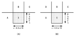
- the positional relationship of the peripheral block A, block B, and block C with respect to the encoding target block X of the encoding target picture is as illustrated. Since the same object exists in the encoding target block X and the block B, bi-directional prediction using the forward reference picture P0 and the backward reference picture P1 is used for the encoding target block X and the block B. On the other hand, the object including the block C has a strong correlation with the forward reference picture P0 and unidirectional prediction is used, and the object including the block A has a strong correlation with the backward reference picture P1 and uses the unidirectional prediction.
- the encoding target block X performs motion compensation prediction with a motion vector ( ⁇ 8, 8) for the reference picture P0, and motion compensation prediction with a motion vector (8, ⁇ 8) for the reference picture P1. I do.
- the block A performs motion compensation prediction with a motion vector (0, 0) with respect to the reference picture P1.
- the block B performs motion compensation prediction with a motion vector of ( ⁇ 8, 8) for the reference picture P0, and performs motion compensation prediction with a motion vector of (8, ⁇ 8) for the reference picture P1.
- Block C performs motion compensation prediction with a motion vector of (0, 0) with respect to reference picture P0.
- the reference index “0” in the direction 0 indicates the reference picture P0
- the reference index “0” in the direction 1 indicates the reference picture P1.
- the reference index refIdxL0X in the direction 0 of the encoding target block X is 0, the motion vector mvL0X is ( ⁇ 8, 8), the reference index refIdxL1X in the direction 1 is 0, and the motion vector mvL1B is (8, ⁇ 8).
- the reference index refIdxL0A in the direction 0 of the peripheral block A is -1, the motion vector mvL0A is (0, 0), the reference index refIdxL1A in the direction 1 is 0, and the motion vector mvL1A is (0, 0).
- the reference index refIdxL0B in the direction 0 of the peripheral block B is 0, the motion vector mvL0B is ( ⁇ 8, 8), the reference index refIdxL1B in the direction 1 is 0, and the motion vector mvL1B is (8, ⁇ 8).
- the reference index refIdxL0C in the direction 0 of the peripheral block C is 0, the motion vector mvL0C is (0, 0), the reference index refIdxL1C in the direction 1 is -1, and the motion vector mvL1C is (0, 0).
- refIdxL0A is -1
- mvL0A is (0, 0)
- refIdxL1C is -1
- mvL1C is (0, 0) because block A and block C are unidirectionally predicted.
- the difference motion vector dmvL0X becomes ( ⁇ 8, 8) by calculating the difference between the motion vector mvL0X of the encoding target block X and the predicted motion vector mvpL0X as shown in Equation 3.
- the predicted motion vector mvpL1X is calculated by calculating the median value of each component of the motion vectors mvL1A, mvL1B, mvL1C in the direction 1 of the peripheral blocks A, B, C as shown in Equation 4, and (0, 0) and Become.
- the difference motion vector dmvL1X is (8, ⁇ 8).
- the encoding target block X that is bi-directionally predicted has a high correlation with the only peripheral block B that is bi-predicted in the same manner, but the reference index is independently determined for each prediction direction.
- the identity is determined, there are peripheral blocks having the same reference index in addition to the peripheral block B. Therefore, in the conventional motion vector prediction method, the predicted motion vector is obtained from the intermediate values of all the neighboring blocks for each prediction direction, and an accurate predicted motion vector cannot be obtained, and the motion vector of the encoding target block Cannot be encoded with reduced redundancy.
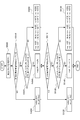
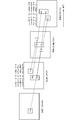
- FIG. 4 is a diagram illustrating a configuration of a moving image encoding apparatus using the motion vector prediction method according to the first embodiment.
- the moving image coding apparatus includes a subtraction unit 100, a prediction error coding unit 110, a code string generation unit 120, a prediction error decoding unit 130, an addition unit 140, a motion compensation prediction method determination unit 150, a frame memory 160, a motion vector coding. Unit 170, motion information storage unit 180, and motion vector number acquisition unit 190.
- Encoding is performed in units of macro blocks.
- the input picture 10 is divided into macroblock units and supplied to the subtraction unit 100 and the motion compensation prediction method determination unit 150.
- the motion compensation prediction method determination unit 150 detects a motion vector for each reference picture from the encoding target macroblock and the reference picture supplied from the frame memory 160 by a technique such as block matching, and the rate is determined from the detected motion vectors.
- a prediction picture is generated by determining an optimal motion compensation prediction method by a distortion optimization method or the like.
- the motion compensation prediction method determination unit 150 supplies the prediction picture generated from the determined motion compensation prediction method to the subtraction unit 100 and the addition unit 140. In addition, the motion compensation prediction method determination unit 150 sends a reference index and a motion vector corresponding to the determined motion compensation prediction method to the motion information storage unit 180.
- the determination of the motion compensation prediction method refers to a method for dividing a prediction block in a macroblock, a method for predicting a divided prediction block (unidirectional prediction / bidirectional prediction), and a reference picture (reference index) in each prediction direction. Is to decide.
- the subtraction unit 100 obtains a prediction error based on the difference between the encoding target macroblock and the prediction picture supplied from the motion compensation prediction method determination unit 150, and supplies the prediction error to the prediction error encoding unit 110.
- the prediction error encoding unit 110 performs processing such as orthogonal transformation and quantization on the prediction error supplied from the subtraction unit 100 to convert it into prediction error code data, and a code string generation unit 120 and a prediction error decoding unit 130. To supply.
- the prediction error decoding unit 130 performs processing such as inverse quantization and inverse orthogonal transform on the prediction error code data supplied from the prediction error encoding unit 110 to convert the prediction error into prediction error, and sends the prediction error to the addition unit 140. Supply.
- the adding unit 140 obtains a decoded picture by adding the prediction error supplied from the prediction error decoding unit 130 and the prediction picture supplied from the motion compensation prediction method determining unit 150, and supplies the decoded picture to the frame memory 160.
- the frame memory 160 holds the decoded picture supplied from the adding unit 140 as a reference picture and supplies it to the motion compensation prediction method determining unit 150.
- the motion information storage unit 180 stores the motion vector and the reference index supplied from the motion compensation prediction method determination unit 150, and supplies the motion vector to the motion vector encoding unit 170.
- the motion information storage unit 180 stores motion vectors and reference indexes for all macroblocks of the input picture, and supplies the motion vectors and reference indexes of neighboring macroblocks of the encoding target macroblock to the motion vector encoding unit 170. To do.
- the motion information storage unit 180 stores the motion vectors and reference indexes for all the macroblocks of the input picture, but the purpose of the motion information storage unit 180 is to store the encoding target macroblock. This is to supply the motion vectors and reference indexes of the peripheral blocks to the motion vector encoding unit 170, and if it can be realized, it is not necessary to store the motion vectors and reference indexes for all macroblocks of the input picture. It is only necessary to memorize as much as possible.
- the motion vector encoding unit 170 is supplied from the motion vector and reference index of the encoding target macroblock supplied from the motion information storage unit 180, the motion vector and reference index of the neighboring macroblock, and the motion vector number acquisition unit 190. Determine the motion vector predictor from the number of motion vectors of the encoding target macroblock and neighboring macroblocks, determine the difference motion vector from the motion vector of the encoding target macroblock and the prediction motion vector, convert it to differential motion vector code data, and code string It supplies to the production
- the code sequence generation unit 120 converts the prediction error code data supplied from the prediction error encoding unit 110 and the differential motion vector code data supplied from the motion vector encoding unit 170 into an output code sequence together with other control information. And output.
- the motion vector number acquisition unit 190 acquires the number of motion vectors for each macroblock from the motion information storage unit 180, and supplies the motion vector number of the encoding target macroblock and the surrounding macroblocks to the motion vector encoding unit 170.
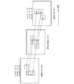
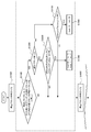
- FIG. 5 is a diagram illustrating a detailed configuration of the motion vector number acquisition unit 190 and the motion vector encoding unit 170 in FIG.
- the motion vector number acquisition unit 190 includes an encoding target block motion vector number acquisition unit 210, a peripheral block motion vector number acquisition unit 220, and a peripheral block identification unit 230.
- the motion vector encoding unit 170 includes a predicted motion vector deriving unit 240, a differential motion vector calculating unit 250, and a differential motion vector encoding unit 260.
- the encoding target block motion vector number acquisition unit 210 acquires the number of motion vectors of the encoding target block from the motion information storage unit 180.
- the peripheral block specifying unit 230 refers to the motion information storage unit 180 and specifies a plurality of encoded peripheral blocks around the encoding target block.
- the peripheral block motion vector number acquisition unit 220 acquires the number of motion vectors of each specified peripheral block from the motion information storage unit 180.
- the motion vector predictor deriving unit 240 receives information on the reference indexes and motion vectors of a plurality of neighboring blocks from the neighboring block specifying unit 230, and obtains the number of motion vectors of the coding target block from the coding target block motion vector number obtaining unit 210.
- the number of motion vectors of peripheral blocks is received from the peripheral block motion vector number acquisition unit 220.
- the prediction motion vector deriving unit 240 identifies a peripheral block as a prediction candidate block when there is only one peripheral block having the same number of motion vectors as the number of motion vectors of the encoding target block among a plurality of peripheral blocks. Then, the motion vector of the prediction candidate block is supplied to the differential motion vector calculation unit 250 as the predicted motion vector MVP.
- the difference motion vector calculation unit 250 calculates a difference motion vector MVD based on the difference between the motion vector MV of the encoding target block read from the motion information storage unit 180 and the prediction motion vector MVP received from the prediction motion vector derivation unit 240. And supplied to the differential motion vector encoding unit 260.
- the differential motion vector encoding unit encodes the differential motion vector MVD and supplies it to the code string generation unit 120.
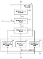
- the prediction motion vector is derived for each prediction block in the encoding target macroblock.
- the first prediction motion vector derivation process is performed in the previous stage, and then the second prediction motion vector derivation process is performed in the subsequent stage.
- the second predictive motion vector derivation process is the same as the conventional predictive motion vector derivation method described in FIG.
- the peripheral block specifying unit 230 determines block A, block B, and block C that are peripheral blocks of the encoding target block X as shown in FIG. 1A (step S1000).
- the peripheral block motion vector number acquisition unit 220 acquires the number of motion vectors of block A, which is a peripheral block, the number of motion vectors of block B, and the number of motion vectors of block C, and the predicted motion vector derivation unit 240 It is checked whether or not there is only one peripheral block N having the same number of motion vectors as that of the encoding target block X among the blocks A, B, and C (step S1100).
- the motion vector predictor deriving unit 240 identifies the peripheral block as a prediction candidate block, and It is checked whether or not the number of motion vectors in block X is 2 (step S1200).
- the motion vector in the single prediction direction Z (forward L0 or backward L1) is set as the predicted motion vector of the encoding target block X (step S1400).
- the single prediction direction Z is a direction in which a motion vector exists.
- the second prediction As the motion vector deriving process, the conventional processes after step 5000 are performed.
- peripheral blocks A, B, and C were at the positions shown in FIG. 1A, but the peripheral blocks are limited to the positions shown in FIG. Instead, any position may be used as long as it is an encoded block.
- the number of peripheral blocks is not necessarily three, but may be two or more.
- the peripheral block is not only a block in the same picture that is spatially adjacent to the current block, but also a reference picture that is encoded immediately before it is temporally adjacent to the current block. It may be a block at the same position as the block or a block adjacent thereto.
- the process after step 5000 is performed as the second predicted motion vector derivation process, but the process is not limited to the process after step 5000.
- the motion vector of any one of a plurality of peripheral blocks having the same number of motion vectors as the encoding target block X May be used as a predicted motion vector, or a weighted average of motion vectors of a plurality of peripheral blocks having the same number of motion vectors as the encoding target block X may be obtained and used as a predicted motion vector.
- the motion vector of any one of the neighboring blocks may be used as a predicted motion vector, and the motion vectors of a plurality of neighboring blocks may be used.
- a weighted average may be obtained and used as a predicted motion vector.
- the prediction motion vector derivation method of the first embodiment is applied to the specific example described in FIG. Since the only peripheral block having the same number of motion vectors as the number of motion vectors 2 of the encoding target block X is the block B, the predicted motion vectors mvpL0X and mvpL1X of the encoding target block X are expressed by ( ⁇ 8 , 8) and (8, -8).
- the differential motion vectors dmvL0X and dmvL1X are (0, 0) and (0, 0) from Equation 9, respectively.
- the motion vector of the peripheral block having the same number of motion vectors as the number of motion vectors of the encoding target block is used as the prediction motion vector. Even if the motion of an object having a temporal correlation different from the motion of the encoding target block exists in the neighboring blocks, the motion vector redundancy of the encoding target block is derived by deriving the predicted motion vector according to the original motion. Can be encoded.
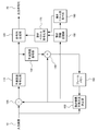
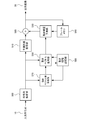
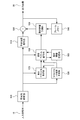
- FIG. 7 is a diagram illustrating a configuration of a moving image decoding apparatus using the motion vector prediction method according to the first embodiment.
- the video decoding apparatus includes a code string analysis unit 500, a prediction error decoding unit 510, an addition unit 520, a motion compensation prediction unit 530, a frame memory 540, a motion vector decoding unit 550, a motion information storage unit 560, and a motion vector number acquisition unit. 570.
- Decoding is performed in units of macroblocks.
- the input code string 10 is supplied to the code string analysis unit 500.
- the code string analysis unit 500 decodes and acquires the prediction error encoded data, the difference motion vector, the reference index, and the macroblock type from the input code string 10.
- the code string analysis unit 500 provides the prediction error encoded data to the prediction error decoding unit 510, the difference motion vector and the reference index to the motion vector decoding unit 550, and the macroblock type to the motion vector number acquisition unit 570 in units of prediction blocks. Supply.
- the subsequent processing is repeated four times within the macro block.
- the prediction error decoding unit 510 converts the prediction error encoded data supplied from the code string analysis unit 500 into a prediction error by performing processing such as inverse quantization and inverse orthogonal transform, and supplies the prediction error to the addition unit 520. .
- the motion vector decoding unit 550 includes the difference motion vector and reference index of the decoding target macroblock supplied from the code string analysis unit 500, and the number of motion vectors of the decoding target macroblock and neighboring macroblocks supplied from the motion vector number acquisition unit 570. Then, a motion vector is obtained from the motion vector and the reference index of the neighboring macroblock supplied from the motion information storage unit 560, and a motion vector is decoded from the difference motion vector and the motion vector predictor of the decoding target macroblock. The vector and the reference index are supplied to the motion compensation prediction unit 530 and also supplied to the motion information storage unit 560. A detailed motion vector decoding method will be described later.
- the motion information storage unit 560 stores the motion vector and reference index supplied from the motion vector decoding unit 550, and supplies the stored motion vector and reference index to the motion vector decoding unit 550 as necessary.
- the motion vector number acquisition unit 570 acquires the number of motion vectors for each macroblock from the macroblock type supplied from the code stream analysis unit 500, and calculates the number of motion vectors of the decoding target macroblock and the surrounding macroblocks as the motion vector decoding unit 550. To supply.
- the acquisition of the number of motion vectors can be determined from the number of differential motion vectors and the number of reference indexes in addition to the acquisition from the macroblock type.
- the motion compensated prediction unit 530 generates a prediction value using the motion vector and reference index supplied from the motion vector decoding unit 550 and the reference picture supplied from the frame memory 540, and supplies the prediction value to the addition unit 520.
- the addition unit 520 generates a decoded value by adding the prediction error supplied from the prediction error decoding unit 510 and the prediction value supplied from the motion compensation prediction unit 530, supplies the decoded value to the frame memory 540, and as an image output 60 Output.
- the frame memory 540 stores the decoded picture supplied from the adding unit 520, and supplies the stored decoded picture as a reference picture to the motion compensation prediction unit 530 as necessary.
- FIG. 8 is a diagram illustrating the detailed configuration of the motion vector number acquisition unit 570 and the motion vector decoding unit 550 of FIG.
- the motion vector number acquisition unit 570 includes a decoding target block motion vector number acquisition unit 610, a peripheral block motion vector number acquisition unit 620, and a peripheral block identification unit 630.
- the motion vector decoding unit 550 includes a predicted motion vector deriving unit 640 and a motion vector calculating unit 650.
- the decoding target block motion vector number acquisition unit 610 acquires the number of motion vectors of the decoding target block from the code string analysis unit 500.
- the peripheral block specifying unit 230 refers to the motion information storage unit 560 and specifies a plurality of decoded peripheral blocks around the decoding target block.
- the peripheral block motion vector number acquisition unit 620 acquires the number of motion vectors of each specified peripheral block from the motion information storage unit 560.
- the motion vector predictor deriving unit 640 receives information on reference indexes and motion vectors of a plurality of neighboring blocks from the neighboring block specifying unit 630, and obtains the number of motion vectors of the decoding target block from the decoding target block motion vector number obtaining unit 610.
- the number of motion vectors of surrounding blocks is received from the motion vector number acquisition unit 620.
- the predicted motion vector deriving unit 640 specifies, as a prediction candidate block, when there is only one peripheral block having the same number of motion vectors as the number of motion vectors of the decoding target block among the plurality of peripheral blocks. Then, the motion vector of the prediction candidate block is supplied to the motion vector calculation unit 650 as a predicted motion vector MVP.
- the motion vector calculation unit 650 calculates the motion vector MV by adding the difference motion vector MVD of the decoding target block received from the code string analysis unit 500 and the prediction motion vector MVP received from the prediction motion vector derivation unit 640. And supplied to the motion compensation prediction unit 530.
- the method of deriving a predicted motion vector by the moving picture decoding apparatus according to the first embodiment is based on the moving picture coding apparatus according to the first embodiment if “the encoding target block” is read as “the decoding target block”. Since it is the same as the method of deriving the predicted motion vector, detailed description is omitted.
- FIG. 9 is a diagram illustrating a configuration of a moving image encoding apparatus using the motion vector prediction method according to the second embodiment.
- the moving image coding apparatus includes a subtraction unit 100, a prediction error coding unit 110, a code string generation unit 120, a prediction error decoding unit 130, an addition unit 140, a motion compensation prediction method determination unit 150, a frame memory 160, a motion vector coding.
- Unit 170, motion information storage unit 180, motion vector number acquisition unit 190, and macroblock boundary determination unit 200 is a subtraction unit 100, a prediction error coding unit 110, a code string generation unit 120, a prediction error decoding unit 130, an addition unit 140, a motion compensation prediction method determination unit 150, a frame memory 160, a motion vector coding.
- Unit 170 motion information storage unit 180, motion vector number acquisition unit 190, and macroblock boundary determination unit 200.
- Subtraction unit 100, prediction error encoding unit 110, code sequence generation unit 120, prediction error decoding unit 130, addition unit 140, motion compensation prediction method determination unit 150, frame memory 160, motion information storage unit of the second embodiment 180 and the motion vector number acquisition unit 190 have the same configurations as those of the first embodiment.
- a motion vector encoding unit 170 and a macroblock boundary determination unit 200 different from those in the first embodiment will be described with reference to FIGS. 9 and 10.
- the macroblock boundary determining unit 200 determines whether or not the encoding target block touches the macroblock boundary. If the encoding target block touches the macroblock boundary, the macroblock boundary flag is set to 1, and the encoding target block is a macro. When the block boundary is not touched, the macroblock boundary flag is set to 0 and the macroblock boundary flag is supplied to the motion vector encoding unit 170.
- Whether or not it touches the macroblock boundary can be determined using, for example, a prediction block number.
- the prediction block number will be described later.
- the motion vector encoding unit 170 is supplied from the motion information storage unit 180, the motion vector and reference index of the encoding target macroblock, the motion vector and reference index of the surrounding macroblock, and the motion supplied from the motion vector number acquisition unit 190.
- a prediction motion vector is obtained from the number of vectors and the macroblock boundary flag supplied from the macroblock boundary determination unit 200, and a difference motion vector is obtained from the motion vector of the encoding target macroblock and the prediction motion vector to obtain difference motion vector code data.
- the data is converted and supplied to the code string generation unit 120.
- the peripheral block specifying unit 230 determines block A, block B, block C, and block D, which are peripheral blocks of the encoding target block X, as shown in FIG. 1B (step S2000).
- the macroblock boundary determination unit 200 checks the value of the macroblock boundary flag (step S2100).
- the peripheral block motion vector number acquisition unit 220 acquires the number of motion vectors of the block A, block B, block C, and block D, which are peripheral blocks.
- the predicted motion vector deriving unit 240 checks whether or not there is only one peripheral block N having the same number of motion vectors as the number of motion vectors of the encoding target block X among the peripheral blocks A, B, C, and D. (Step S2200). After step S2200, the processing after step S1200 of the first embodiment is performed.
- step S5000 the process after step S5000 is performed as the second motion vector predictor derivation process as described in the first embodiment.
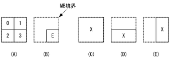
- FIG. 11A shows the prediction block number when the macroblock is divided into four 8 ⁇ 8 prediction blocks.
- FIG. 11B there is a block E with a prediction block number of 3 that does not touch the macroblock boundary.
- the block E includes the same object as the other blocks in the macro block and exhibits the same movement, the block E has one block X as shown in FIG. 11C, FIG. 11D, or FIG. Are likely to be encoded. Therefore, when the block E exists as an independent prediction block, it is unlikely that the block E and other blocks in the macro block include the same object and exhibit the same motion. Therefore, in such a case, it is desirable to proceed to the second predicted motion vector derivation process without intentionally performing the determination based on the number of motion vectors, whereby sudden motion vectors can be eliminated.
- the condition that it does not touch the macroblock boundary is that “the peripheral block is in the same macroblock. In other words.
- the encoding target block when the encoding target block is in contact with the macroblock boundary, the encoding target block is considered in consideration of the number of motion vectors of the encoding target block and the number of motion vectors of the surrounding blocks.
- the number of motion vectors of the current block and the number of motion vectors of the neighboring blocks are not taken into consideration, thereby reducing false detection of predicted motion vectors and predicting motion vectors according to the original motion. Can be derived.
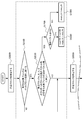
- FIG. 12 is a diagram illustrating a configuration of a video decoding apparatus using the motion vector prediction method according to the second embodiment.
- the moving picture decoding apparatus includes a code string analysis unit 500, a prediction error decoding unit 510, an addition unit 520, a motion compensation prediction unit 530, a frame memory 540, a motion vector decoding unit 550, a motion information storage unit 560, and a motion vector number acquisition unit 570. , And a macroblock boundary determination unit 580.
- the prediction error decoding unit 510, the addition unit 520, the motion compensation prediction unit 530, the frame memory 540, the motion information storage unit 560, and the motion vector number acquisition unit 570 of the second embodiment are the same as those of the first embodiment. It is the same as the configuration marked with.
- a code string analysis unit 500, a motion vector decoding unit 550, and a macroblock boundary determination unit 580 that are different from those in the first embodiment will be described.
- the code string analysis unit 500 decodes and acquires the prediction error encoded data, the difference motion vector, the reference index, and the macroblock type from the input code string 10.
- the code string analysis unit 500 provides the prediction error encoded data to the prediction error decoding unit 510, the difference motion vector and the reference index to the motion vector decoding unit 550, and the macroblock type to the motion vector number acquisition unit 570 in units of prediction blocks.
- the prediction block number is supplied to the macroblock boundary determination unit 580.
- the macroblock boundary determination unit 580 determines whether or not the decoding target block touches the macroblock boundary from the prediction block number supplied from the code string analysis unit 500, and if the decoding target block touches the macroblock boundary, the macroblock boundary If the flag is set to 1 and the decoding target block does not touch the macroblock boundary, the macroblock boundary flag is set to 0 and the macroblock boundary flag is supplied to the motion vector decoding unit 550.
- the motion vector decoding unit 550 includes the difference motion vector and reference index of the decoding target macroblock supplied from the code string analysis unit 500, and the number of motion vectors of the decoding target macroblock and neighboring macroblocks supplied from the motion vector number acquisition unit 570. Then, a prediction motion vector is obtained using the macroblock boundary flag supplied from the macroblock boundary determination unit 580, the motion vector of the neighboring blocks supplied from the motion information storage unit 560, and the reference index, and the difference motion vector of the decoding target macroblock The motion vector is decoded from the predicted motion vector, and the decoded motion vector and the reference index are supplied to the motion compensation prediction unit 530 and supplied to the motion information storage unit 560.
- the method of deriving a predicted motion vector by the moving picture decoding apparatus according to the second embodiment is based on the moving picture coding apparatus according to the second embodiment, if “encoding target block” is read as “decoding target block”. Since it is the same as the method of deriving the predicted motion vector, detailed description is omitted.
- the positional relationship of the surrounding block A, block B, and block C with respect to the encoding target block X is as shown in the figure.
- two forward reference pictures P0 and P1 and one backward reference picture P2 are used for the current picture. Since the same object exists in the encoding target block X and the block B, bi-directional prediction using the forward reference picture P1 and the backward reference picture P2 is used for the encoding target block X and the block B.
- bidirectional prediction of the forward reference picture P0 and backward reference picture P2 is used for the object including the block A, and unidirectional prediction of the forward reference picture P1 is used for the object including the block C.
- the encoding target block X performs motion compensation prediction with a motion vector ( ⁇ 8, 8) for the reference picture P1, and motion compensation prediction with a motion vector (8, ⁇ 8) for the reference picture P2. I do.
- the block A performs motion compensation prediction with a motion vector (0, 0) for the reference picture P0, and performs motion compensation prediction with a motion vector (0, 0) for the reference picture P2.
- the block B performs motion compensation prediction with a motion vector ( ⁇ 8, 8) for the reference picture P1, and performs motion compensation prediction with a motion vector (8, ⁇ 8) for the reference picture P2.
- Block C performs motion compensation prediction with a motion vector of (0, 0) with respect to reference picture P1.
- the reference index “0” in the direction 0 indicates the reference picture P1
- the reference index “1” in the direction 0 indicates the reference picture P0
- the reference index “0” in the direction 1 indicates the reference picture P2.
- the reference index refIdxL0X in the direction 0 of the encoding target block X is 0, the motion vector mvL0X is ( ⁇ 8, 8), the reference index refIdxL1X in the direction 1 is 0, and the motion vector mvL1B is (8, ⁇ 8).
- the reference index refIdxL0A in the direction 0 of the peripheral block A is 1, the motion vector motion vector mvL0A is (0, 0), the reference index refIdxL1A in the direction 1 is 0, and the mvL1A is (0, 0).
- the reference index refIdxL0B in the direction 0 of the peripheral block B is 0, the motion vector mvL0B is ( ⁇ 8, 8), the reference index refIdxL1B in the direction 1 is 0, and the motion vector mvL1B is (8, ⁇ 8).
- the reference index refIdxL0C in the direction 0 of the peripheral block C is 0, the motion vector mvL0C is (0, 0), the reference index refIdxL1C in the direction 1 is -1, and the motion vector mvL1C is (0, 0).
- the reference index having a value equal to the reference index refIdxL0X of the encoding target block X is the reference index refIdxL0B of the block B and the reference index refIdxL0C of the block C. Therefore, the predicted motion vector mvpL0X is obtained by calculating the median value of each component of the motion vectors mvL0A, mvL0B, and mvL0C in the direction 0 of the peripheral blocks A, B, and C as shown in Equation 10 ( 0,0).
- the difference motion vector dmvL0X becomes ( ⁇ 8, 8) by calculating the difference between the motion vector mvL0X of the encoding target block X and the predicted motion vector mvpL0X as shown in Expression 11.
- the predicted motion vector mvpL1X is obtained by calculating the median of each component of the motion vectors mvL1A, mvL1B, and mvL1C in the direction 1 of the peripheral blocks A, B, and C as shown in Equation 12, and (0, 0) and Become.
- the difference motion vector dmvL1X is (8, ⁇ 8).
- the encoding target block X that is bi-directionally predicted has a high correlation with the only peripheral block B that is bi-predicted in the same manner, but the reference index is independently determined for each prediction direction.
- the identity is determined, there are peripheral blocks having the same reference index in addition to the peripheral block B. Therefore, in the conventional motion vector prediction method, the predicted motion vector is obtained from the intermediate values of all the neighboring blocks for each prediction direction, and an accurate predicted motion vector cannot be obtained, and the motion vector of the encoding target block Cannot be encoded with reduced redundancy.
- the encoding target block Since there are two blocks A and B as peripheral blocks equal to the number of motion vectors 2, the second motion vector prediction process is executed, and the same result as the conventional motion vector prediction method is obtained. Coding with reduced redundancy of motion vector of the target block is not possible.
- the third embodiment of the present invention not only the number of motion vectors is the same between the current block and the neighboring blocks, but also the reference picture is the same.
- the motion vector prediction method put into the evaluation is used.
- the configuration of the video encoding device and video decoding device using the motion vector prediction method of the third embodiment is the same as that of the video encoding device and video decoding device of the first embodiment.
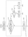
- a motion vector encoding unit 170 and a motion vector decoding unit 550 having different operations from those of the first embodiment will be described with reference to FIG. However, in the case of the motion vector decoding unit 550, “encoding target block” is replaced with “decoding target block” in the following description.
- the motion vector predictor deriving unit 240 checks whether the number of motion vectors of the encoding target block X is 2 ( Step S1200).
- the motion vector predictor deriving unit 240 refers to the L0 direction reference index refIdxL0X of the encoding target block X in the L0 direction. It is checked whether the index refIdxL0N is equal to the reference index refIdxL1X in the L1 direction of the encoding target block X and the reference index refIdxL1N in the L1 direction of the peripheral block N (step S3000).
- step S1300 When the condition of step S3000 is satisfied, the process of step S1300 is performed as in the first embodiment, and the motion vector of the neighboring block N is predicted for the encoding target block X in both directions (forward L0 and backward L1). Let it be a motion vector.
- step S5000 which is a conventional motion vector prediction method, is performed.
- the motion vector predictor deriving unit 240 determines that the reference index refIdxLZX in the single prediction direction Z (forward L0 or backward L1) of the encoding target block X is Then, it is checked whether or not it is equal to the reference index refIdxLZN in the LZ direction of the peripheral block N (step S3100).
- step S3100 When the condition of step S3100 is satisfied, the process of step S1400 is performed as in the first embodiment, and the motion vector of the block N in the single prediction direction Z is set as the predicted motion vector of the encoding target block X. If the condition of step S3100 is not satisfied, the process after step S5000, which is a conventional motion vector prediction method, is performed.
- the differential motion vectors dmvL0X and dmvL1X are (0, 0) and (0, 0) from Equation 15, respectively.
- the prediction motion vector derivation method of the third embodiment even when there are a plurality of peripheral blocks having the same number of motion vectors as the number of motion vectors of the encoding target block, reference to each prediction direction is performed. By considering whether the index is the same, that is, whether the reference picture of the encoding target block and the surrounding block match, a prediction motion vector according to the original motion is derived, and the motion vector of the encoding target block Can be encoded with reduced redundancy.
- the number and positions of the peripheral blocks are arbitrary.
- the front L0 reference pictures are many and the rear L1 reference pictures are few.
- the number of neighboring blocks may be changed depending on the prediction direction, for example, 4 blocks are specified for the forward L0 and 2 blocks are specified for the backward L1.
- any method of deriving a motion vector predictor according to any embodiment, a first motion vector predictor derivation process in the previous stage, a second motion vector predictor derivation process in the subsequent stage (conventional motion vector derivation method),
- the peripheral block specifying method can be adaptively selected according to the derivation accuracy and processing amount of the predicted motion vector.
- the moving image encoded stream output from the moving image encoding apparatus of the embodiment described above has a specific data format so that it can be decoded according to the encoding method used in the embodiment. Therefore, the moving picture decoding apparatus corresponding to the moving picture encoding apparatus can decode the encoded stream of this specific data format.
- the encoded stream When a wired or wireless network is used to exchange an encoded stream between a moving image encoding device and a moving image decoding device, the encoded stream is converted into a data format suitable for the transmission form of the communication path. It may be transmitted.
- a video transmission apparatus that converts the encoded stream output from the video encoding apparatus into encoded data in a data format suitable for the transmission form of the communication channel and transmits the encoded data to the network, and receives the encoded data from the network Then, a moving image receiving apparatus that restores the encoded stream and supplies the encoded stream to the moving image decoding apparatus is provided.
- the moving image transmitting apparatus is a memory that buffers the encoded stream output from the moving image encoding apparatus, a packet processing unit that packetizes the encoded stream, and transmission that transmits the packetized encoded data via the network.
- the moving image receiving apparatus generates a coded stream by packetizing the received data, a receiving unit that receives the packetized coded data via a network, a memory that buffers the received coded data, and packet processing. And a packet processing unit provided to the video decoding device.
- the above processing relating to encoding and decoding can be realized as a transmission, storage, and reception device using hardware, and is also stored in a ROM (Read Only Memory), a flash memory, or the like. It can also be realized by firmware or software such as a computer.
- the firmware program and software program can be provided by recording them on a computer-readable recording medium, provided from a server through a wired or wireless network, or provided as a data broadcast of terrestrial or satellite digital broadcasting. Is also possible.
- motion vector deriving unit 650 motion vector calculating unit.
Abstract
A motion vector decoding unit (550) derives the motion vector of a block predicted to be subjected to decoding, on the basis of the motion vectors of one of the candidate blocks within candidate blocks selected from surrounding blocks. A motion compensation prediction unit (530) performs motion compensation prediction using the derived motion vector. The motion vector decoding unit (550) determines whether to have a second block serve as a candidate block according to whether the number motion vectors of the first block and the number of motion vectors of the second block are the same, and whether the reference index that indicates a reference picture referred to by the motion vectors of the first block is the same as the reference index that indicates a reference picture referred to by the motion vectors of the second block.
Description
本発明は、動き補償予測を用いた映像復号技術に関し、特に動き補償予測で利用する動きベクトルの導出技術に関する。
The present invention relates to a video decoding technique using motion compensated prediction, and more particularly to a technique for deriving a motion vector used in motion compensated prediction.
映像圧縮符号化では、一般に、ピクチャ間の時間方向の相関性を利用して圧縮効率を上げるために動き補償予測が利用される。動き補償予測では、動きベクトルで示される動きの方向と量を考慮して参照ピクチャから予測値を得る。動き補償予測で得られた予測値と符号化対象ピクチャの画素値との差分値を符号化することで冗長度を取り除き、圧縮効率を高めることができる。
In video compression coding, motion compensated prediction is generally used to increase compression efficiency by utilizing temporal correlation between pictures. In motion compensation prediction, a prediction value is obtained from a reference picture in consideration of the direction and amount of motion indicated by a motion vector. By encoding the difference value between the prediction value obtained by motion compensation prediction and the pixel value of the encoding target picture, redundancy can be removed and compression efficiency can be increased.
最新の映像圧縮符号化であるMPEG-4AVCなどでは、1つのピクチャを、ピクチャ内符号化するIピクチャ、単方向の動き補償予測が可能なPピクチャ、単方向または双方向の動き補償予測が可能なBピクチャとして符号化する。
In MPEG-4AVC, which is the latest video compression coding, one picture can be I picture for intra-picture coding, P picture capable of unidirectional motion compensation prediction, unidirectional or bidirectional motion compensation prediction Encoded as a B picture.
ある符号化対象ブロックの動きベクトルを符号化する場合、最初に周辺ブロックから予測動きベクトルを導出する。そして、符号化対象ブロックの動きベクトルと予測動きベクトルとの差分動きベクトルを算出し、差分動きベクトルをエントロピー符号化する。ここで、周辺ブロックから予測動きベクトルを導出するのは、符号化対象ブロックの動きベクトルが周辺ブロックの動きベクトルと相関性を持つと考えられるためである。エントロピー符号化ではこの相関性を利用して差分動きベクトルの絶対値が小さいほど動きベクトルの圧縮効率が高くなるように圧縮する。
When encoding a motion vector of a certain encoding target block, first, a prediction motion vector is derived from the neighboring blocks. Then, a differential motion vector between the motion vector of the encoding target block and the predicted motion vector is calculated, and the differential motion vector is entropy encoded. Here, the reason why the motion vector predictor is derived from the peripheral block is that the motion vector of the encoding target block is considered to have a correlation with the motion vector of the peripheral block. In entropy coding, this correlation is used to perform compression so that the motion vector compression efficiency increases as the absolute value of the difference motion vector decreases.
特許文献1に符号化対象ブロックの周辺ブロック用いた動きベクトルの予測方法が開示されている。
Patent Document 1 discloses a motion vector prediction method using peripheral blocks of an encoding target block.
上記の従来の動きベクトル符号化方法では、予測動きベクトルを前方、後方などの予測方向毎に導出しているため、符号化対象ブロックの動きとは異なる時間相関性を有するオブジェクトの動きが周辺ブロック内に存在する場合、符号化対象ブロック内のオブジェクトの本来の動きとは無関係な予測動きベクトルが導出され、動きベクトルの圧縮効率が向上しないことがあった。
In the above-described conventional motion vector encoding method, since the prediction motion vector is derived for each prediction direction such as forward and backward, the motion of an object having a temporal correlation different from the motion of the block to be encoded is a neighboring block. If it exists in the block, a motion vector predictor unrelated to the original motion of the object in the encoding target block is derived, and the compression efficiency of the motion vector may not be improved.
本発明はこうした状況に鑑みてなされたものであり、その目的は、符号化側での動きベクトルの圧縮効率を向上させつつ、復号側での動きベクトル導出の正確性を向上させることができる動きベクトル符号化技術及び動きベクトル復号技術を提供することにある。
The present invention has been made in view of such a situation, and an object of the present invention is to provide a motion that can improve the accuracy of motion vector derivation on the decoding side while improving the compression efficiency of the motion vector on the encoding side. It is to provide a vector encoding technique and a motion vector decoding technique.
上記課題を解決するために、本発明のある態様の動画像復号装置は、動画像の各ピクチャを分割したブロック単位で動き補償予測を用いて符号化された符号列を復号する動画像復号装置であって、復号対象予測ブロックの動きベクトルを、前記復号対象予測ブロックの周辺ブロックから選択される候補ブロックの内の何れかの候補ブロックの動きベクトルに基づき導出する動き情報導出部(550)と、前記動き情報導出部により導出された動きベクトルを用いた動き補償予測により前記復号対象予測ブロックの予測信号を生成する動き補償予測部(530)とを備える。前記動き情報導出部(550)は、第1のブロックの動きベクトル数と第2のブロックの動きベクトル数が同一であり、かつ前記第1のブロックの動きベクトルが参照する参照ピクチャを示す参照インデックスと前記第2のブロックの動きベクトルが参照する参照ピクチャを示す参照インデックスが同一であるか否かによって、前記第2のブロックを候補ブロックとするか否かを判定する。
In order to solve the above-described problem, a moving picture decoding apparatus according to an aspect of the present invention is a moving picture decoding apparatus that decodes a code string encoded using motion compensated prediction in units of blocks obtained by dividing each picture of a moving picture. A motion information deriving unit (550) for deriving a motion vector of a decoding target prediction block based on a motion vector of one of candidate blocks selected from neighboring blocks of the decoding target prediction block; A motion compensation prediction unit (530) that generates a prediction signal of the decoding target prediction block by motion compensation prediction using the motion vector derived by the motion information deriving unit. The motion information deriving unit (550) has the same number of motion vectors as the first block and the number of motion vectors as the second block, and a reference index indicating a reference picture to which the motion vector of the first block refers. Whether or not the second block is a candidate block is determined based on whether or not the reference index indicating the reference picture referred to by the motion vector of the second block is the same.
本発明のさらに別の態様は、動画像復号方法である。この方法は、動画像の各ピクチャを分割したブロック単位で動き補償予測を用いて符号化された符号列を復号する動画像復号方法であって、復号対象予測ブロックの動きベクトルを、前記復号対象予測ブロックの周辺ブロックから選択される候補ブロックの内の何れかの候補ブロックの動きベクトルに基づき導出する動き情報導出ステップと、前記動き情報導出ステップにより導出された動きベクトルを用いた動き補償予測により前記復号対象予測ブロックの予測信号を生成する動き補償予測ステップとを備える。前記動き情報導出ステップは、第1のブロックの動きベクトル数と第2のブロックの動きベクトル数が同一であり、かつ前記第1のブロックの動きベクトルが参照する参照ピクチャを示す参照インデックスと前記第2のブロックの動きベクトルが参照する参照ピクチャを示す参照インデックスが同一であるか否かによって、前記第2のブロックを候補ブロックとするか否かを判定する。
Still another aspect of the present invention is a moving picture decoding method. This method is a moving picture decoding method for decoding a code string encoded using motion compensated prediction in units of blocks obtained by dividing each picture of a moving picture, and a motion vector of a decoding target prediction block is calculated as the decoding target. A motion information deriving step derived based on a motion vector of any candidate block of candidate blocks selected from neighboring blocks of the prediction block, and motion compensated prediction using the motion vector derived by the motion information deriving step A motion compensation prediction step of generating a prediction signal of the decoding target prediction block. In the motion information deriving step, the number of motion vectors of the first block and the number of motion vectors of the second block are the same, and a reference index indicating a reference picture referenced by the motion vector of the first block and the first block Whether or not the second block is a candidate block is determined based on whether or not the reference indexes indicating the reference pictures referenced by the motion vectors of the two blocks are the same.
なお、以上の構成要素の任意の組合せ、本発明の表現を方法、装置、システム、記録媒体、コンピュータプログラムなどの間で変換したものもまた、本発明の態様として有効である。
It should be noted that an arbitrary combination of the above-described components and a conversion of the expression of the present invention between a method, an apparatus, a system, a recording medium, a computer program, and the like are also effective as an aspect of the present invention.
本発明によれば、周辺ブロックの動きベクトルを考慮することにより、符号化側での動きベクトルの圧縮効率を向上させつつ、動きベクトル導出の正確性を向上させることができる。
According to the present invention, by considering the motion vectors of the peripheral blocks, it is possible to improve the accuracy of motion vector derivation while improving the compression efficiency of motion vectors on the encoding side.
まず、本発明の実施の形態の前提となる技術を説明する。
First, the technology that is the premise of the embodiment of the present invention will be described.
現在、MPEG(Moving Picture Experts Group)などの符号化方式に準拠した装置およびシステムが普及している。そのような符号化方式では、時間軸上に連続する複数の画像をデジタル信号の情報として取り扱う。その際、効率の高い情報の放送、伝送または蓄積などを目的とし、時間方向の冗長性を利用した動き補償予測、および空間方向の冗長性を利用した離散コサイン変換などの直交変換を用いて圧縮符号化する。
Currently, devices and systems compliant with coding schemes such as MPEG (Moving Picture Experts Group) are in widespread use. In such an encoding method, a plurality of images that are continuous on the time axis are handled as digital signal information. At that time, for the purpose of broadcasting, transmitting or storing highly efficient information, compression using motion compensation prediction using temporal redundancy and orthogonal transform such as discrete cosine transform using spatial redundancy Encode.
1995年にはMPEG-2ビデオ(ISO/IEC 13818-2)符号化方式が、汎用の映像圧縮符号化方式として制定され、DVD(Digital Versatile Disk)およびD-VHS(登録商標)規格のデジタルVTRによる磁気テープなどの蓄積メディア、ならびにデジタル放送などのアプリケーションとして広く用いられている。
In 1995, the MPEG-2 video (ISO / IEC 13818-2) encoding system was established as a general-purpose video compression encoding system, and the digital VTR of DVD (Digital Versatile Disk) and D-VHS (registered trademark) standards. Is widely used as an application for storage media such as magnetic tape and digital broadcasting.
さらに、2003年に、国際標準化機構(ISO)と国際電気標準会議(IEC)のジョイント技術委員会(ISO/IEC)と、国際電気通信連合電気通信標準化部門(ITU-T)の共同作業によってMPEG-4 AVC/H.264と呼ばれる符号化方式(ISO/IECでは14496-10、ITU-TではH.264の規格番号がつけられている。以下、これをMPEG-4AVCと呼ぶ)が国際標準として制定された。
Furthermore, in 2003, a joint effort between the International Organization for Standardization (ISO) and the International Electrotechnical Commission (IEC) Joint Technical Committee (ISO / IEC) and the International Telecommunication Union Telecommunication Standardization Sector (ITU-T) -4 AVC / H.264 (ISO / IEC 14496-10, ITU-T H.264 standard number, hereinafter referred to as MPEG-4AVC) is an international standard. It was enacted as.
これらの符号化方式では、動き補償予測が利用される。動き補償予測では、動きベクトルで示される動きの方向と量を考慮して参照ピクチャから予測値を得る。動き補償予測で得られた予測値と符号化対象ピクチャの画素値との差分値を符号化することで冗長度を取り除き、圧縮効率を高めることができる。
In these encoding methods, motion compensation prediction is used. In motion compensation prediction, a prediction value is obtained from a reference picture in consideration of the direction and amount of motion indicated by a motion vector. By encoding the difference value between the prediction value obtained by motion compensation prediction and the pixel value of the encoding target picture, redundancy can be removed and compression efficiency can be increased.
動き補償予測の利用方法によって、ピクチャは3つのタイプに分けられる。動き補償予測を利用しないIピクチャ、単方向の動き補償予測が可能なPピクチャ、単方向または双方向の動き補償予測が可能なBピクチャである。
ピ ク チ ャ Pictures are divided into three types depending on how motion compensated prediction is used. These are an I picture that does not use motion compensated prediction, a P picture that can perform unidirectional motion compensated prediction, and a B picture that can perform unidirectional or bidirectional motion compensated prediction.
MPEG-2のPピクチャでは、表示順序で直前のIピクチャまたはPピクチャを参照ピクチャとしてマクロブロック単位で動き補償予測を行う。これに対して、MPEG-4AVCでは、複数の符号化済みピクチャを参照ピクチャとして用いることができ、この中から予測ブロック(説明は後述)毎に最適なものを選択して動き補償予測を行うことができる。なお、表示順序で先行するピクチャに加えて、表示順序で後続のピクチャも参照することができる。
In the MPEG-2 P picture, motion compensation prediction is performed in units of macroblocks using the immediately preceding I picture or P picture in the display order as a reference picture. On the other hand, in MPEG-4 AVC, a plurality of encoded pictures can be used as reference pictures, and motion compensation prediction is performed by selecting an optimum picture for each prediction block (described later). Can do. In addition to the preceding picture in the display order, it is possible to refer to subsequent pictures in the display order.
また、MPEG-2のBピクチャでは、表示順序で前方1枚の参照ピクチャを利用しての動き補償予測、後方1枚の参照ピクチャを利用しての動き補償予測、またはその2枚の参照ピクチャを平均しての動き補償予測のいずれかを行うことができる。これに対して、MPEG-4AVCでは、表示順序で前方1枚、後方1枚という制約にとらわれず、前方や後方に関係なく任意の参照ピクチャを動き補償予測のために利用することができる。さらに、Bピクチャを参照ピクチャとして参照することもできる。
Also, in the MPEG-2 B picture, motion compensation prediction using one reference picture in the display order, motion compensation prediction using one reference picture in the back, or the two reference pictures Any of motion compensated prediction can be performed by averaging. On the other hand, in MPEG-4 AVC, any reference picture can be used for motion compensation prediction regardless of the forward or backward direction, regardless of the restriction of one front and one rear in the display order. Furthermore, a B picture can be referred to as a reference picture.
このように、MPEG-4AVCでは任意の符号化済みピクチャを参照することが可能なため、復号したピクチャを参照フレームメモリに格納して管理する。
As described above, since any encoded picture can be referred to in MPEG-4 AVC, the decoded picture is stored in the reference frame memory and managed.
MPEG-4AVCでは、参照フレームメモリに格納されているピクチャをあらかじめ定められた方法で並べて参照ピクチャリストを作成し、その符号化ストリームにそのインデックスを記述することにより、参照ピクチャを指定している。ここで、「参照ピクチャリスト」とは、動き補償予測で利用する参照フレーム内の参照ピクチャを並び替えることのできるリストである。参照ピクチャリストを用いて参照ピクチャを利用頻度に応じて並び替えることで符号化効率を向上させることができる。
In MPEG-4 AVC, a reference picture is specified by arranging pictures stored in a reference frame memory in a predetermined method to create a reference picture list and describing the index in the encoded stream. Here, the “reference picture list” is a list in which reference pictures in a reference frame used in motion compensation prediction can be rearranged. Coding efficiency can be improved by rearranging the reference pictures according to the frequency of use using the reference picture list.
また、参照ピクチャリストはスライス毎に付加されるスライスヘッダ内で参照ピクチャリスト変更情報を送ることにより、上述したリストを並び替えることも可能である。
Also, the reference picture list can be rearranged by sending reference picture list change information in a slice header added for each slice.
MPEG-4AVCの動き補償予測では、予測ブロック単位で、参照ピクチャリストに登録された符号化済みのピクチャを参照ピクチャとし、動きベクトルで示される動きの方向と量を考慮して参照ピクチャから予測値を算出する。
In motion compensated prediction of MPEG-4 AVC, an encoded picture registered in the reference picture list is used as a reference picture for each prediction block, and a predicted value is calculated from the reference picture in consideration of the direction and amount of motion indicated by the motion vector. Is calculated.
参照ピクチャリストは2方向用意されている。一般的に、符号化対象ピクチャの時間的に前方向の符号化済みピクチャを登録する参照ピクチャリストL0と、一般的に、符号化対象ピクチャの時間的に後方向の符号化済みピクチャを登録する参照ピクチャリストL1である。Pピクチャでは参照ピクチャリストL0が利用され、Bピクチャでは参照ピクチャリストL0及び参照ピクチャリストL1が利用される。
The reference picture list is prepared in two directions. In general, a reference picture list L0 for registering a temporally forward-coded picture of an encoding target picture and, in general, a temporally backward-encoded picture of a encoding target picture is registered. Reference picture list L1. The P picture uses the reference picture list L0, and the B picture uses the reference picture list L0 and the reference picture list L1.
参照ピクチャリストL0による動き補償予測の方向を方向0、参照ピクチャリストL1による動き補償予測の方向を方向1とする。
The direction of motion compensated prediction by the reference picture list L0 is direction 0, and the direction of motion compensated prediction by the reference picture list L1 is direction 1.
予測ブロックについて説明すると、ピクチャはまず、水平16画素×垂直16画素のマクロブロック(以下、MB)単位に分割され、MBは更に、水平16画素×垂直16画素、水平16画素×垂直8画素、水平8画素×垂直16画素、水平8画素×垂直8画素、水平8画素×垂直4画素、水平4画素×垂直8画素、水平4画素×垂直4画素のいずれかの予測ブロックに分割される。
The prediction block will be described. First, a picture is divided into units of macro blocks (hereinafter referred to as MB) of 16 horizontal pixels × vertical 16 pixels, and the MB is further divided into 16 horizontal pixels × 16 vertical pixels, 16 horizontal pixels × 8 vertical pixels, The prediction block is divided into any of prediction blocks of horizontal 8 pixels × vertical 16 pixels, horizontal 8 pixels × vertical 8 pixels, horizontal 8 pixels × vertical 4 pixels, horizontal 4 pixels × vertical 8 pixels, and horizontal 4 pixels × vertical 4 pixels.
Pピクチャの予測ブロックには、動き方向と動き量を示す動きベクトルと、参照ピクチャリストの参照ピクチャを示す参照インデックスとが1つずつ割り当てられる。Bピクチャの予測ブロックには、動き方向と動き量を示す動きベクトルと、参照ピクチャリストの参照ピクチャを示す参照インデックスとが1つまたは2つずつ割り当てられる。
A motion vector indicating the motion direction and the motion amount and a reference index indicating a reference picture in the reference picture list are assigned to each prediction block of the P picture. One or two motion vectors indicating a motion direction and a motion amount and a reference index indicating a reference picture in a reference picture list are assigned to a prediction block of a B picture.
動きベクトルと参照インデックスが1つずつ割り当てられた予測ブロック(以下、単方向予測)では、その動きベクトルと参照インデックスが指し示す参照ピクチャの画素値が予測値となる。一方、動きベクトルと参照インデックスが2つずつ割り当てられた予測ブロック(以下、双方向予測)では、それぞれの動きベクトルと参照インデックスが指し示す参照ピクチャの画素値の平均値が予測値となる。
In a prediction block to which a motion vector and a reference index are assigned one by one (hereinafter referred to as unidirectional prediction), a pixel value of a reference picture indicated by the motion vector and the reference index is a prediction value. On the other hand, in a prediction block (hereinafter referred to as bi-directional prediction) in which two motion vectors and two reference indexes are assigned, an average value of pixel values of reference pictures indicated by the respective motion vectors and reference indexes is a predicted value.
次に、従来の予測動きベクトル導出方法として、特許文献1やMPEG-4AVCの予測動きベクトルの導出方法を図1及び図2を参照して説明する。以降、特に断らない限り、ブロックは予測ブロックのことを示すものとする。
Next, as a conventional method for deriving a motion vector predictor, a method for deriving a motion vector predictor of Patent Document 1 and MPEG-4 AVC will be described with reference to FIGS. Hereinafter, unless otherwise specified, a block indicates a prediction block.
図1(A)のように、符号化対象ブロックXの周辺ブロックであるブロックA、ブロックB、およびブロックCを決定する(ステップS5000)。ここで、ブロックAの方向0の参照インデックスをrefIdxL0A、方向0の動きベクトルをmvL0Aと定義し、方向1の参照インデックスをrefIdxL1A、方向1の動きベクトルをmvL1Aと定義する。以下同様に、ブロックBのrefIdxL0B、mvL0B、refIdxL1B、mvL1B、ブロックCのrefIdxL0C、mvL0C、refIdxL1C、mvL1Cを定義する。
As shown in FIG. 1A, block A, block B, and block C that are peripheral blocks of the encoding target block X are determined (step S5000). Here, the reference index in the direction 0 of the block A is defined as refIdxL0A, the motion vector in the direction 0 is defined as mvL0A, the reference index in the direction 1 is defined as refIdxL1A, and the motion vector in the direction 1 is defined as mvL1A. Similarly, refIdxL0B, mvL0B, refIdxL1B, mvL1B of block B, and refIdxL0C, mvL0C, refIdxL1C, mvL1C of block C are defined.
符号化対象ブロックXにおいて方向0の動き補償予測が行われているかどうかを検査する(ステップS5010)。
It is checked whether or not motion compensation prediction in the direction 0 is performed in the encoding target block X (step S5010).
方向0の動き補償予測が行われていない場合(ステップS5010のNO)、符号化対象ブロックXの方向0の参照インデックスrefIdxL0Xを-1、動きベクトルmvL0Xを(0,0)とする(ステップS5030)。
When motion compensation prediction in the direction 0 is not performed (NO in step S5010), the reference index refIdxL0X in the direction 0 of the encoding target block X is set to −1, and the motion vector mvL0X is set to (0, 0) (step S5030). .
方向0の動き補償予測が行われている場合(ステップS5010のYES)、3つの周辺ブロックA、B、Cの方向0の参照インデックスrefIdxL0A、refIdxL0B、refIdxL0Cの内、いずれか一つだけが符号化対象ブロックXの参照インデックスであるrefIdxL0Xと同じであるかどうかを検査し(ステップS5020)、符号化対象ブロックXと参照インデックスが一致する周辺ブロックが一つだけ存在する場合(ステップS5020のYES)、その周辺ブロックNの動きベクトルmvL0Nを符号化対象ブロックXの予測動きベクトルmvpL0Xとする(ステップS5040)。
When motion compensation prediction in the direction 0 is performed (YES in step S5010), only one of the three peripheral blocks A, B, and C in the reference index refIdxL0A, refIdxL0B, and refIdxL0C in the direction 0 is encoded. It is checked whether it is the same as refIdxL0X, which is the reference index of the target block X (step S5020). If there is only one peripheral block whose reference index matches the encoding target block X (YES in step S5020), The motion vector mvL0N of the peripheral block N is set as the predicted motion vector mvpL0X of the encoding target block X (step S5040).
符号化対象ブロックXと参照インデックスが一致する周辺ブロックが存在しないか、2つ以上存在する場合(ステップS5020のNO)、式1に示すように、周辺ブロックA、B、Cの方向0の動きベクトルmvL0A、mvL0B、mvL0Cの各成分の中央値を予測動きベクトルmvpL0Xとする(ステップS5050)。
mvpL0X(x)=Median[mvL0A(x),mvL0B(x),mvL0C(x)]
mvpL0X(y)=Median[mvL0A(y),mvL0B(y),mvL0C(y)]
(式1) When there is no peripheral block whose reference index matches the encoding target block X or there are two or more peripheral blocks (NO in step S5020), the movement in thedirection 0 of the peripheral blocks A, B, and C as shown in Equation 1 The median value of each component of the vectors mvL0A, mvL0B, and mvL0C is set as a predicted motion vector mvpL0X (step S5050).
mvpL0X (x) = Media [mvL0A (x), mvL0B (x), mvL0C (x)]
mvpL0X (y) = Media [mvL0A (y), mvL0B (y), mvL0C (y)]
(Formula 1)
mvpL0X(x)=Median[mvL0A(x),mvL0B(x),mvL0C(x)]
mvpL0X(y)=Median[mvL0A(y),mvL0B(y),mvL0C(y)]
(式1) When there is no peripheral block whose reference index matches the encoding target block X or there are two or more peripheral blocks (NO in step S5020), the movement in the
mvpL0X (x) = Media [mvL0A (x), mvL0B (x), mvL0C (x)]
mvpL0X (y) = Media [mvL0A (y), mvL0B (y), mvL0C (y)]
(Formula 1)
符号化対象ブロックXにおいて方向1の動き補償予測についても方向0と同様の処理を行う(ステップS5110~ステップS5150)。
In the encoding target block X, the same processing as in direction 0 is performed for motion compensated prediction in direction 1 (steps S5110 to S5150).
以上述べた従来方法の課題を説明する。従来の動きベクトル予測方法ではメディアンフィルタを利用することによって予測動きベクトルが突発的な値を取るのを回避している。しかし、メディアンフィルタでは最も効率的な動きベクトルを予測値として利用できないという課題がある。
Explain the problems of the conventional method described above. In a conventional motion vector prediction method, a predicted motion vector is prevented from taking an unexpected value by using a median filter. However, the median filter has a problem that the most efficient motion vector cannot be used as a predicted value.
そのため、従来の動きベクトル予測方法ではメディアンフィルタの前段に、予測方向毎に符号化対象ブロックの参照インデックスと同じ参照インデックスを持つ周辺ブロックが一つだけ存在する場合には、その周辺ブロックの動きベクトルを優先して予測動きベクトルとする仕組みが導入されている。
Therefore, in the conventional motion vector prediction method, when there is only one peripheral block having the same reference index as the reference index of the encoding target block for each prediction direction in the preceding stage of the median filter, the motion vector of the peripheral block is present. Has been introduced as a predicted motion vector.
一般的に、動きベクトルはオブジェクトの動きに依存するため、オブジェクトの動きは時間方向の相関性を有している。ところが、従来の動きベクトル予測方法では、符号化対象ブロックと周辺ブロックの参照インデックスが一致するかどうかの検証を予測方向毎に独立して行うため、符号化対象ブロックの動きとは異なる時間相関性を有するオブジェクトの動きが周辺ブロック内に存在する場合、符号化対象ブロックの本来の動きを正しく予測できない課題があった。
Generally, since the motion vector depends on the motion of the object, the motion of the object has a correlation in the time direction. However, in the conventional motion vector prediction method, whether or not the reference indexes of the encoding target block and the neighboring blocks match is independently verified for each prediction direction, and therefore, the temporal correlation different from the motion of the encoding target block. When there is a motion of an object having a symbol in a peripheral block, there is a problem that the original motion of the encoding target block cannot be predicted correctly.
図3を参照して、このような従来の動きベクトル予測方法の課題を具体例により説明する。
Referring to FIG. 3, a problem of such a conventional motion vector prediction method will be described with a specific example.
符号化対象ピクチャの符号化対象ブロックXに対する周辺のブロックA、ブロックB、ブロックCの位置関係は図示される通りである。符号化対象ブロックXとブロックBには同じオブジェクトが存在するため、符号化対象ブロックXとブロックBについては、前方参照ピクチャP0と後方参照ピクチャP1を用いた双方向予測が用いられる。他方、ブロックCを含むオブジェクトは前方参照ピクチャP0との相関が強く、単方向予測が用いられ、ブロックAを含むオブジェクトは後方参照ピクチャP1との相関が強く、単方向予測が用いられる。
The positional relationship of the peripheral block A, block B, and block C with respect to the encoding target block X of the encoding target picture is as illustrated. Since the same object exists in the encoding target block X and the block B, bi-directional prediction using the forward reference picture P0 and the backward reference picture P1 is used for the encoding target block X and the block B. On the other hand, the object including the block C has a strong correlation with the forward reference picture P0 and unidirectional prediction is used, and the object including the block A has a strong correlation with the backward reference picture P1 and uses the unidirectional prediction.
符号化対象ブロックXは、参照ピクチャP0に対して動きベクトルが(-8,8)となる動き補償予測を行い、参照ピクチャP1に対して動きベクトルが(8,-8)となる動き補償予測を行う。ブロックAは、参照ピクチャP1に対して動きベクトルが(0,0)となる動き補償予測を行う。ブロックBは、参照ピクチャP0に対して動きベクトルが(-8,8)となる動き補償予測を行い、参照ピクチャP1に対して動きベクトルが(8,-8)となる動き補償予測を行う。ブロックCは、参照ピクチャP0に対して動きベクトルが(0,0)となる動き補償予測を行う。
The encoding target block X performs motion compensation prediction with a motion vector (−8, 8) for the reference picture P0, and motion compensation prediction with a motion vector (8, −8) for the reference picture P1. I do. The block A performs motion compensation prediction with a motion vector (0, 0) with respect to the reference picture P1. The block B performs motion compensation prediction with a motion vector of (−8, 8) for the reference picture P0, and performs motion compensation prediction with a motion vector of (8, −8) for the reference picture P1. Block C performs motion compensation prediction with a motion vector of (0, 0) with respect to reference picture P0.
ここで、方向0の参照インデックスの'0'は参照ピクチャP0を示し、方向1の参照インデックスの'0'は参照ピクチャP1を示すとする。
Here, it is assumed that the reference index “0” in the direction 0 indicates the reference picture P0, and the reference index “0” in the direction 1 indicates the reference picture P1.
符号化対象ブロックXの方向0の参照インデックスrefIdxL0Xは0、動きベクトルmvL0Xは(-8,8)、方向1の参照インデックスrefIdxL1Xは0、動きベクトルmvL1Bは(8,-8)である。
The reference index refIdxL0X in the direction 0 of the encoding target block X is 0, the motion vector mvL0X is (−8, 8), the reference index refIdxL1X in the direction 1 is 0, and the motion vector mvL1B is (8, −8).
周辺ブロックAの方向0の参照インデックスrefIdxL0Aは-1、動きベクトルmvL0Aは(0,0)、方向1の参照インデックスrefIdxL1Aは0、動きベクトルmvL1Aは(0,0)である。
The reference index refIdxL0A in the direction 0 of the peripheral block A is -1, the motion vector mvL0A is (0, 0), the reference index refIdxL1A in the direction 1 is 0, and the motion vector mvL1A is (0, 0).
周辺ブロックBの方向0の参照インデックスrefIdxL0Bは0、動きベクトルmvL0Bは(-8,8)、方向1の参照インデックスrefIdxL1Bは0、動きベクトルmvL1Bは(8,-8)である。
The reference index refIdxL0B in the direction 0 of the peripheral block B is 0, the motion vector mvL0B is (−8, 8), the reference index refIdxL1B in the direction 1 is 0, and the motion vector mvL1B is (8, −8).
周辺ブロックCの方向0の参照インデックスrefIdxL0Cは0、動きベクトルmvL0Cは(0,0)、方向1の参照インデックスrefIdxL1Cは-1、動きベクトルmvL1Cは(0,0)である。
The reference index refIdxL0C in the direction 0 of the peripheral block C is 0, the motion vector mvL0C is (0, 0), the reference index refIdxL1C in the direction 1 is -1, and the motion vector mvL1C is (0, 0).
ここで、refIdxL0Aが-1、mvL0Aが(0,0)、refIdxL1Cが-1、mvL1Cが(0,0)となるのはブロックAとブロックCが単方向予測のためである。
Here, refIdxL0A is -1, mvL0A is (0, 0), refIdxL1C is -1, and mvL1C is (0, 0) because block A and block C are unidirectionally predicted.
上述の従来の動きベクトル予測方法では、符号化対象ブロックXの方向0については、符号化対象ブロックXの参照インデックスrefIdxL0Xに等しい値をもつ参照インデックスは、ブロックBの参照インデックスrefIdxL0BとブロックCの参照インデックスrefIdxL0Cの2つが存在することから、予測動きベクトルmvpL0Xは、式2のように周辺ブロックA、B、Cの方向0の動きベクトルmvL0A、mvL0B、mvL0Cの各成分の中央値を計算することにより、(0,0)となる。
mvpL0X=(Median[0,-8,0],Median[0,8,0])=(0,0)
(式2) In the above-described conventional motion vector prediction method, for thedirection 0 of the encoding target block X, the reference index having a value equal to the reference index refIdxL0X of the encoding target block X is the reference index refIdxL0B of block B and the reference of block C Since there are two indexes refIdxL0C, the predicted motion vector mvpL0X is obtained by calculating the median value of each component of the motion vectors mvL0A, mvL0B, and mvL0C in the direction 0 of the peripheral blocks A, B, and C as shown in Equation 2. , (0, 0).
mvpL0X = (Media [0, −8,0], Median [0,8,0]) = (0,0)
(Formula 2)
mvpL0X=(Median[0,-8,0],Median[0,8,0])=(0,0)
(式2) In the above-described conventional motion vector prediction method, for the
mvpL0X = (Media [0, −8,0], Median [0,8,0]) = (0,0)
(Formula 2)
このとき、差分動きベクトルdmvL0Xは、式3のように符号化対象ブロックXの動きベクトルmvL0Xと予測動きベクトルmvpL0Xの差分を計算することにより、(-8,8)となる。
dmvL0X=mvL0X-mvpL0X=(-8-0,8-0)=(-8,8)
(式3) At this time, the difference motion vector dmvL0X becomes (−8, 8) by calculating the difference between the motion vector mvL0X of the encoding target block X and the predicted motion vector mvpL0X as shown inEquation 3.
dmvL0X = mvL0X-mvpL0X = (-8-0,8-0) = (-8,8)
(Formula 3)
dmvL0X=mvL0X-mvpL0X=(-8-0,8-0)=(-8,8)
(式3) At this time, the difference motion vector dmvL0X becomes (−8, 8) by calculating the difference between the motion vector mvL0X of the encoding target block X and the predicted motion vector mvpL0X as shown in
dmvL0X = mvL0X-mvpL0X = (-8-0,8-0) = (-8,8)
(Formula 3)
同様に、符号化対象ブロックXの方向1については、符号化対象ブロックXの参照インデックスrefIdxL1Xに等しい値をもつ参照インデックスは、ブロックAの参照インデックスrefIdxL1AとブロックBの参照インデックスrefIdxL1Bの2つが存在することから、予測動きベクトルmvpL1Xは、式4のように周辺ブロックA、B、Cの方向1の動きベクトルmvL1A、mvL1B、mvL1Cの各成分の中央値を計算することにより、(0,0)となる。
mvpL1X=(Median[0,8,0],Median[0,-8,0])=(0,0)
(式4) Similarly, for thedirection 1 of the encoding target block X, there are two reference indexes having a value equal to the reference index refIdxL1X of the encoding target block X: the reference index refIdxL1A of block A and the reference index refIdxL1B of block B Therefore, the predicted motion vector mvpL1X is calculated by calculating the median value of each component of the motion vectors mvL1A, mvL1B, mvL1C in the direction 1 of the peripheral blocks A, B, C as shown in Equation 4, and (0, 0) and Become.
mvpL1X = (Media [0,8,0], Median [0, −8,0]) = (0,0)
(Formula 4)
mvpL1X=(Median[0,8,0],Median[0,-8,0])=(0,0)
(式4) Similarly, for the
mvpL1X = (Media [0,8,0], Median [0, −8,0]) = (0,0)
(Formula 4)
このとき、差分動きベクトルdmvL1X、式5のように符号化対象ブロックXの動きベクトルmvL1Xと予測動きベクトルmvpL1Xの差分を計算することにより、(8,-8)となる。
dmvL1X=mvL1X-mvpL1X=(8-0,-8-0)=(8,-8)
(式5) At this time, by calculating the difference between the motion vector mvL1X of the encoding target block X and the predicted motion vector mvpL1X as shown in Equation 5, the difference motion vector dmvL1X is (8, −8).
dmvL1X = mvL1X-mvpL1X = (8-0, -8-0) = (8, -8)
(Formula 5)
以上のように、本来は、双方向予測された符号化対象ブロックXは、同じように双方向予測された唯一の周辺ブロックBと高い相関を持つが、予測方向毎に独立して参照インデックスの同一性を判断した場合、周辺ブロックB以外にも同じ参照インデックスをもつ周辺ブロックが存在する。そのため、従来の動きベクトル予測方法では、予測方向毎に予測動きベクトルをすべての周辺ブロックの中間値によって求めることになってしまい、正確な予測動きベクトルが得られず、符号化対象ブロックの動きベクトルの冗長度を削減した符号化ができない。
As described above, the encoding target block X that is bi-directionally predicted has a high correlation with the only peripheral block B that is bi-predicted in the same manner, but the reference index is independently determined for each prediction direction. When the identity is determined, there are peripheral blocks having the same reference index in addition to the peripheral block B. Therefore, in the conventional motion vector prediction method, the predicted motion vector is obtained from the intermediate values of all the neighboring blocks for each prediction direction, and an accurate predicted motion vector cannot be obtained, and the motion vector of the encoding target block Cannot be encoded with reduced redundancy.
以上述べた前提技術および従来技術を踏まえて、以下、本発明の第1の実施の形態を詳細に説明する。
The first embodiment of the present invention will be described below in detail based on the above-mentioned prerequisite technology and conventional technology.
図4は、第1の実施の形態の動きベクトル予測方法を用いた動画像符号化装置の構成を示す図である。動画像符号化装置は、減算部100、予測誤差符号化部110、符号列生成部120、予測誤差復号部130、加算部140、動き補償予測方法決定部150、フレームメモリ160、動きベクトル符号化部170、動き情報記憶部180、および動きベクトル数取得部190を含む。
FIG. 4 is a diagram illustrating a configuration of a moving image encoding apparatus using the motion vector prediction method according to the first embodiment. The moving image coding apparatus includes a subtraction unit 100, a prediction error coding unit 110, a code string generation unit 120, a prediction error decoding unit 130, an addition unit 140, a motion compensation prediction method determination unit 150, a frame memory 160, a motion vector coding. Unit 170, motion information storage unit 180, and motion vector number acquisition unit 190.
まず、動画像符号化装置による動画像符号化処理の流れについて説明する。
First, the flow of the video encoding process by the video encoding device will be described.
符号化はマクロブロックを単位として行う。入力ピクチャ10はマクロブロック単位に分割され、減算部100及び動き補償予測方法決定部150に供給される。
Encoding is performed in units of macro blocks. The input picture 10 is divided into macroblock units and supplied to the subtraction unit 100 and the motion compensation prediction method determination unit 150.
動き補償予測方法決定部150は、符号化対象マクロブロックとフレームメモリ160より供給される参照ピクチャから、ブロックマッチングなどの手法によって各参照ピクチャについて動きベクトルを検出し、検出した動きベクトルの中からレート歪み最適化法などによって最適な動き補償予測方法を決定して予測ピクチャを生成する。
The motion compensation prediction method determination unit 150 detects a motion vector for each reference picture from the encoding target macroblock and the reference picture supplied from the frame memory 160 by a technique such as block matching, and the rate is determined from the detected motion vectors. A prediction picture is generated by determining an optimal motion compensation prediction method by a distortion optimization method or the like.
動き補償予測方法決定部150は、決定した動き補償予測方法から生成された予測ピクチャを減算部100及び加算部140に供給する。また、動き補償予測方法決定部150は、決定した動き補償予測方法に対応する参照インデックスと動きベクトルを動き情報記憶部180に送る。
The motion compensation prediction method determination unit 150 supplies the prediction picture generated from the determined motion compensation prediction method to the subtraction unit 100 and the addition unit 140. In addition, the motion compensation prediction method determination unit 150 sends a reference index and a motion vector corresponding to the determined motion compensation prediction method to the motion information storage unit 180.
ここで、動き補償予測方法の決定とは、マクロブロック内の予測ブロックの分割方法、分割された予測ブロックの予測方法(単方向予測/双方向予測)、各予測方向の参照ピクチャ(参照インデックス)を決めることである。
Here, the determination of the motion compensation prediction method refers to a method for dividing a prediction block in a macroblock, a method for predicting a divided prediction block (unidirectional prediction / bidirectional prediction), and a reference picture (reference index) in each prediction direction. Is to decide.
減算部100は、符号化対象マクロブロックと動き補償予測方法決定部150から供給される予測ピクチャの差分により予測誤差を求め、予測誤差符号化部110に供給する。
The subtraction unit 100 obtains a prediction error based on the difference between the encoding target macroblock and the prediction picture supplied from the motion compensation prediction method determination unit 150, and supplies the prediction error to the prediction error encoding unit 110.
予測誤差符号化部110は、減算部100から供給される予測誤差に対して直交変換や量子化などの処理を行って予測誤差符号データに変換し、符号列生成部120及び予測誤差復号部130に供給する。
The prediction error encoding unit 110 performs processing such as orthogonal transformation and quantization on the prediction error supplied from the subtraction unit 100 to convert it into prediction error code data, and a code string generation unit 120 and a prediction error decoding unit 130. To supply.
予測誤差復号部130は、予測誤差符号化部110から供給される予測誤差符号データに対して逆量子化や逆直交変換などの処理を行って予測誤差に変換し、予測誤差を加算部140に供給する。
The prediction error decoding unit 130 performs processing such as inverse quantization and inverse orthogonal transform on the prediction error code data supplied from the prediction error encoding unit 110 to convert the prediction error into prediction error, and sends the prediction error to the addition unit 140. Supply.
加算部140は、予測誤差復号部130から供給される予測誤差と動き補償予測方法決定部150から供給される予測ピクチャを加算することにより復号ピクチャを求め、フレームメモリ160に供給する。
The adding unit 140 obtains a decoded picture by adding the prediction error supplied from the prediction error decoding unit 130 and the prediction picture supplied from the motion compensation prediction method determining unit 150, and supplies the decoded picture to the frame memory 160.
フレームメモリ160は、加算部140から供給される復号ピクチャを参照ピクチャとして保持し、動き補償予測方法決定部150に供給する。
The frame memory 160 holds the decoded picture supplied from the adding unit 140 as a reference picture and supplies it to the motion compensation prediction method determining unit 150.
動き情報記憶部180は、動き補償予測方法決定部150から供給される動きベクトルと参照インデックスを記憶し、その動きベクトルを動きベクトル符号化部170に供給する。動き情報記憶部180は、入力ピクチャの全てのマクロブロックに関する動きベクトルと参照インデックスを記憶しており、符号化対象マクロブロックの周辺マクロブロックの動きベクトルと参照インデックスを動きベクトル符号化部170に供給する。
The motion information storage unit 180 stores the motion vector and the reference index supplied from the motion compensation prediction method determination unit 150, and supplies the motion vector to the motion vector encoding unit 170. The motion information storage unit 180 stores motion vectors and reference indexes for all macroblocks of the input picture, and supplies the motion vectors and reference indexes of neighboring macroblocks of the encoding target macroblock to the motion vector encoding unit 170. To do.
なお、第1の実施の形態では動き情報記憶部180は、入力ピクチャの全てのマクロブロックに関する動きベクトルと参照インデックスを記憶するとしたが、動き情報記憶部180の目的は、符号化対象マクロブロックの周辺ブロックの動きベクトルと参照インデックスを動きベクトル符号化部170に供給することであり、それを実現することができれば入力ピクチャの全てのマクロブロックに関する動きベクトルと参照インデックスを記憶する必要はなく、必要とされる分だけ記憶すればよい。
In the first embodiment, the motion information storage unit 180 stores the motion vectors and reference indexes for all the macroblocks of the input picture, but the purpose of the motion information storage unit 180 is to store the encoding target macroblock. This is to supply the motion vectors and reference indexes of the peripheral blocks to the motion vector encoding unit 170, and if it can be realized, it is not necessary to store the motion vectors and reference indexes for all macroblocks of the input picture. It is only necessary to memorize as much as possible.
動きベクトル符号化部170は、動き情報記憶部180から供給される符号化対象マクロブロックの動きベクトルと参照インデックス、周辺マクロブロックの動きベクトルと参照インデックス、及び動きベクトル数取得部190から供給される符号化対象マクロブロックと周辺マクロブロックの動きベクトル数から予測動きベクトルを求め、符号化対象マクロブロックの動きベクトルと予測動きベクトルから差分動きベクトルを求めて差分動きベクトル符号データに変換し、符号列生成部120に供給する。詳細な動きベクトルの予測方法については後述する。
The motion vector encoding unit 170 is supplied from the motion vector and reference index of the encoding target macroblock supplied from the motion information storage unit 180, the motion vector and reference index of the neighboring macroblock, and the motion vector number acquisition unit 190. Determine the motion vector predictor from the number of motion vectors of the encoding target macroblock and neighboring macroblocks, determine the difference motion vector from the motion vector of the encoding target macroblock and the prediction motion vector, convert it to differential motion vector code data, and code string It supplies to the production | generation part 120. A detailed motion vector prediction method will be described later.
符号列生成部120は、予測誤差符号化部110から供給される予測誤差符号データ、および動きベクトル符号化部170から供給される差分動きベクトル符号データをその他の制御情報などと共に出力符号列に変換して出力する。
The code sequence generation unit 120 converts the prediction error code data supplied from the prediction error encoding unit 110 and the differential motion vector code data supplied from the motion vector encoding unit 170 into an output code sequence together with other control information. And output.
動きベクトル数取得部190は、動き情報記憶部180からマクロブロック毎の動きベクトル数を取得し、符号化対象マクロブロックと周辺マクロブロックの動きベクトル数を動きベクトル符号化部170に供給する。
The motion vector number acquisition unit 190 acquires the number of motion vectors for each macroblock from the motion information storage unit 180, and supplies the motion vector number of the encoding target macroblock and the surrounding macroblocks to the motion vector encoding unit 170.
なお、動きベクトル数の取得に関しては、動き情報記憶部180からマクロブロック毎の動きベクトル数を取得する方法以外にも、動き補償予測方法決定部150により決定された動き補償予測方法を示す情報などから取得することも可能である。
Regarding the acquisition of the number of motion vectors, in addition to the method of acquiring the number of motion vectors for each macroblock from the motion information storage unit 180, information indicating the motion compensation prediction method determined by the motion compensation prediction method determination unit 150, etc. It is also possible to obtain from.
図5は、図4の動きベクトル数取得部190および動きベクトル符号化部170の詳細な構成を説明する図である。
FIG. 5 is a diagram illustrating a detailed configuration of the motion vector number acquisition unit 190 and the motion vector encoding unit 170 in FIG.
動きベクトル数取得部190は、符号化対象ブロック動きベクトル数取得部210、周辺ブロック動きベクトル数取得部220、および周辺ブロック特定部230を含む。
The motion vector number acquisition unit 190 includes an encoding target block motion vector number acquisition unit 210, a peripheral block motion vector number acquisition unit 220, and a peripheral block identification unit 230.
動きベクトル符号化部170は、予測動きベクトル導出部240、差分動きベクトル算出部250、および差分動きベクトル符号化部260を含む。
The motion vector encoding unit 170 includes a predicted motion vector deriving unit 240, a differential motion vector calculating unit 250, and a differential motion vector encoding unit 260.
符号化対象ブロック動きベクトル数取得部210は、動き情報記憶部180から符号化対象ブロックの動きベクトルの数を取得する。周辺ブロック特定部230は、動き情報記憶部180を参照して、符号化対象ブロックの周辺にあって符号化済みの複数の周辺ブロックを特定する。周辺ブロック動きベクトル数取得部220は、特定された各周辺ブロックの動きベクトルの数を動き情報記憶部180から取得する。
The encoding target block motion vector number acquisition unit 210 acquires the number of motion vectors of the encoding target block from the motion information storage unit 180. The peripheral block specifying unit 230 refers to the motion information storage unit 180 and specifies a plurality of encoded peripheral blocks around the encoding target block. The peripheral block motion vector number acquisition unit 220 acquires the number of motion vectors of each specified peripheral block from the motion information storage unit 180.
予測動きベクトル導出部240は、周辺ブロック特定部230から複数の周辺ブロックの参照インデックスと動きベクトルの情報を受け取り、符号化対象ブロック動きベクトル数取得部210から符号化対象ブロックの動きベクトル数を、周辺ブロック動きベクトル数取得部220から周辺ブロックの動きベクトル数を受け取る。
The motion vector predictor deriving unit 240 receives information on the reference indexes and motion vectors of a plurality of neighboring blocks from the neighboring block specifying unit 230, and obtains the number of motion vectors of the coding target block from the coding target block motion vector number obtaining unit 210. The number of motion vectors of peripheral blocks is received from the peripheral block motion vector number acquisition unit 220.
予測動きベクトル導出部240は、複数の周辺ブロックの内、符号化対象ブロックの動きベクトル数と同一の動きベクトル数を有する周辺ブロックがただ一つ存在する場合、その周辺ブロックを予測候補ブロックとして特定し、その予測候補ブロックの動きベクトルを予測動きベクトルMVPとして差分動きベクトル算出部250に供給する。
The prediction motion vector deriving unit 240 identifies a peripheral block as a prediction candidate block when there is only one peripheral block having the same number of motion vectors as the number of motion vectors of the encoding target block among a plurality of peripheral blocks. Then, the motion vector of the prediction candidate block is supplied to the differential motion vector calculation unit 250 as the predicted motion vector MVP.
差分動きベクトル算出部250は、動き情報記憶部180から読み出した符号化対象ブロックの動きベクトルMVと、予測動きベクトル導出部240から受け取った予測動きベクトルMVPとの差分により差分動きベクトルMVDを算出し、差分動きベクトル符号化部260に供給する。
The difference motion vector calculation unit 250 calculates a difference motion vector MVD based on the difference between the motion vector MV of the encoding target block read from the motion information storage unit 180 and the prediction motion vector MVP received from the prediction motion vector derivation unit 240. And supplied to the differential motion vector encoding unit 260.
差分動きベクトル符号化部は、差分動きベクトルMVDを符号化し、符号列生成部120に供給する。
The differential motion vector encoding unit encodes the differential motion vector MVD and supplies it to the code string generation unit 120.
次に、図1、図2、および図6を参照して、第1の実施の形態の予測動きベクトルの導出方法の詳細を説明する。予測動きベクトルの導出は、符号化対象マクロブロック中の予測ブロック単位に処理を行う。第1の実施の形態の予測動きベクトルの導出方法では、前段で第1の予測動きベクトル導出処理を行った後、後段で第2の予測動きベクトル導出処理を行う。第2の予測動きベクトル導出処理は、図1で説明した従来の予測動きベクトルの導出方法と同じである。
Next, with reference to FIG. 1, FIG. 2, and FIG. 6, details of the method for deriving the motion vector predictor according to the first embodiment will be described. The prediction motion vector is derived for each prediction block in the encoding target macroblock. In the prediction motion vector derivation method according to the first embodiment, the first prediction motion vector derivation process is performed in the previous stage, and then the second prediction motion vector derivation process is performed in the subsequent stage. The second predictive motion vector derivation process is the same as the conventional predictive motion vector derivation method described in FIG.
前段の第1の予測動きベクトル導出処理を説明する。
The first prediction motion vector derivation process in the previous stage will be described.
最初に、周辺ブロック特定部230は、図1(A)のように符号化対象ブロックXの周辺ブロックであるブロックA、ブロックB、およびブロックCを決定する(ステップS1000)。
First, the peripheral block specifying unit 230 determines block A, block B, and block C that are peripheral blocks of the encoding target block X as shown in FIG. 1A (step S1000).
次に、周辺ブロック動きベクトル数取得部220は、周辺ブロックであるブロックAの動きベクトル数、ブロックBの動きベクトル数、ブロックCの動きベクトル数を取得し、予測動きベクトル導出部240は、周辺ブロックA、B、Cの内、符号化対象ブロックXの動きベクトル数と同一の動きベクトル数を有する周辺ブロックNがただ一つ存在するかどうかを検査する(ステップS1100)。
Next, the peripheral block motion vector number acquisition unit 220 acquires the number of motion vectors of block A, which is a peripheral block, the number of motion vectors of block B, and the number of motion vectors of block C, and the predicted motion vector derivation unit 240 It is checked whether or not there is only one peripheral block N having the same number of motion vectors as that of the encoding target block X among the blocks A, B, and C (step S1100).
符号化対象ブロックXと動きベクトル数が同じ周辺ブロックNがただ一つ存在する場合(ステップS1100のYES)、予測動きベクトル導出部240は、その周辺ブロックを予測候補ブロックとして特定し、符号化対象ブロックXの動きベクトル数が2であるかどうかを検査する(ステップS1200)。
When there is only one peripheral block N having the same number of motion vectors as the encoding target block X (YES in step S1100), the motion vector predictor deriving unit 240 identifies the peripheral block as a prediction candidate block, and It is checked whether or not the number of motion vectors in block X is 2 (step S1200).
ただ一つの周辺ブロックNが符号化対象ブロックXと動きベクトル数が同じで、且つ符号化対象ブロックXの動きベクトル数が2である場合(ステップS1200のYES)、式6のように、双方向(前方L0および後方L1)共に周辺ブロックNの動きベクトルを符号化対象ブロックXの予測動きベクトルとする(ステップS1300)。
mvpL0X=mvL0N
mvpL1X=mvL1N
(式6) When only one peripheral block N has the same number of motion vectors as that of the encoding target block X and the number of motion vectors of the encoding target block X is 2 (YES in step S1200), bidirectional expression is obtained as shown in Expression 6. Both (forward L0 and backward L1) use the motion vector of the peripheral block N as the predicted motion vector of the encoding target block X (step S1300).
mvpL0X = mvL0N
mvpL1X = mvL1N
(Formula 6)
ただ一つの周辺ブロックNが符号化対象ブロックXと動きベクトル数が同じで、且つ符号化対象ブロックXの動きベクトル数が2でない場合(ステップ1200のNO)、式7のように、ブロックNの単予測方向Z(前方L0または後方L1)の動きベクトルを符号化対象ブロックXの予測動きベクトルとする(ステップS1400)。なお、単予測方向Zは動きベクトルが存在する方向である。
mvpLZX=mvLZN
(式7) When only one peripheral block N has the same number of motion vectors as the encoding target block X and the number of motion vectors of the encoding target block X is not 2 (NO in step 1200), The motion vector in the single prediction direction Z (forward L0 or backward L1) is set as the predicted motion vector of the encoding target block X (step S1400). The single prediction direction Z is a direction in which a motion vector exists.
mvpLZX = mvLZN
(Formula 7)
いずれの周辺ブロックも符号化対象ブロックXと動きベクトル数が同じでないか、2つ以上の周辺ブロックが符号化対象ブロックXと動きベクトル数が同じである場合(S1000のNO)、第2の予測動きベクトル導出処理として、従来のステップ5000以降の処理を行う。
If none of the neighboring blocks has the same number of motion vectors as the encoding target block X or two or more neighboring blocks have the same number of motion vectors as the coding target block X (NO in S1000), the second prediction As the motion vector deriving process, the conventional processes after step 5000 are performed.
上記の説明では、周辺ブロックであるブロックA、ブロックB、およびブロックCは、図1(A)に示した位置にあったが、周辺ブロックは図1(A)に示した位置に限定するものではなく、符号化済みのブロックであれば任意の位置でよい。また、周辺ブロックは3つである必要はなく、2つ以上であればよい。さらに、周辺ブロックは空間的に符号化対象ブロックと隣接している同じピクチャ内にあるブロックのみならず、時間的に符号化対象ブロックと隣接している直前に符号化した参照ピクチャの符号化対象ブロックと同一位置のブロックまたはそれに隣接するブロックでもよい。
In the above description, peripheral blocks A, B, and C were at the positions shown in FIG. 1A, but the peripheral blocks are limited to the positions shown in FIG. Instead, any position may be used as long as it is an encoded block. Further, the number of peripheral blocks is not necessarily three, but may be two or more. Furthermore, the peripheral block is not only a block in the same picture that is spatially adjacent to the current block, but also a reference picture that is encoded immediately before it is temporally adjacent to the current block. It may be a block at the same position as the block or a block adjacent thereto.
第1の実施の形態では、第2の予測動きベクトル導出処理として、ステップ5000以降の処理を行うとしたが、ステップ5000以降の処理に限定するものではない。たとえば、2つ以上の周辺ブロックが符号化対象ブロックXと動きベクトル数が同じである場合、符号化対象ブロックXと動きベクトル数が同じである複数の周辺ブロックのいずれか一つのブロックの動きベクトルを予測動きベクトルとしてもよく、符号化対象ブロックXと動きベクトル数が同じである複数の周辺ブロックの動きベクトルの加重平均を求めて、予測動きベクトルとしてもよい。また、いずれの周辺ブロックも符号化対象ブロックXと動きベクトル数が同じでない場合も、同様に、いずれか一つの周辺ブロックの動きベクトルを予測動きベクトルとしてもよく、複数の周辺ブロックの動きベクトルの加重平均を求めて、予測動きベクトルとしてもよい。
In the first embodiment, the process after step 5000 is performed as the second predicted motion vector derivation process, but the process is not limited to the process after step 5000. For example, when two or more peripheral blocks have the same number of motion vectors as the encoding target block X, the motion vector of any one of a plurality of peripheral blocks having the same number of motion vectors as the encoding target block X May be used as a predicted motion vector, or a weighted average of motion vectors of a plurality of peripheral blocks having the same number of motion vectors as the encoding target block X may be obtained and used as a predicted motion vector. Similarly, even when none of the neighboring blocks has the same number of motion vectors as the encoding target block X, the motion vector of any one of the neighboring blocks may be used as a predicted motion vector, and the motion vectors of a plurality of neighboring blocks may be used. A weighted average may be obtained and used as a predicted motion vector.
次に、第1の実施の形態の予測動きベクトル導出方法による効果を説明する。
Next, effects of the prediction motion vector deriving method of the first embodiment will be described.
図3で説明した具体例に第1の実施の形態の予測動きベクトル導出方法を適用したとする。符号化対象ブロックXの動きベクトル数2と同じ動きベクトル数を持つただ一つの周辺ブロックはブロックBであることから、符号化対象ブロックXの予測動きベクトルmvpL0X、mvpL1Xは式8からそれぞれ(-8,8)、(8,-8)となる。
mvpL0X=mvL0B=(-8,8)
mvpL1X=mvL1B=(8,-8)
(式8) It is assumed that the prediction motion vector derivation method of the first embodiment is applied to the specific example described in FIG. Since the only peripheral block having the same number of motion vectors as the number ofmotion vectors 2 of the encoding target block X is the block B, the predicted motion vectors mvpL0X and mvpL1X of the encoding target block X are expressed by (−8 , 8) and (8, -8).
mvpL0X = mvL0B = (− 8,8)
mvpL1X = mvL1B = (8, −8)
(Formula 8)
mvpL0X=mvL0B=(-8,8)
mvpL1X=mvL1B=(8,-8)
(式8) It is assumed that the prediction motion vector derivation method of the first embodiment is applied to the specific example described in FIG. Since the only peripheral block having the same number of motion vectors as the number of
mvpL0X = mvL0B = (− 8,8)
mvpL1X = mvL1B = (8, −8)
(Formula 8)
このとき、差分動きベクトルdmvL0X、dmvL1Xは式9からそれぞれ(0,0)、(0,0)となる。
dmvpL0X=mvL0X-mvpL0X=(-8,8)-(-8,8)=(0,0)
dmvpL1X=mvL0X-mvpL0X=(8,-8)-(8,-8)=(0,0)
(式9) At this time, the differential motion vectors dmvL0X and dmvL1X are (0, 0) and (0, 0) from Equation 9, respectively.
dmvpL0X = mvL0X-mvpL0X = (− 8,8) − (− 8,8) = (0,0)
dmvpL1X = mvL0X−mvpL0X = (8, −8) − (8, −8) = (0,0)
(Formula 9)
以上のように、第1の実施の形態の予測動きベクトルの導出方法によれば、符号化対象ブロックの動きベクトル数と同じ動きベクトル数を有する周辺ブロックの動きベクトルを予測動きベクトルにすることによって、符号化対象ブロックの動きとは異なる時間相関性を有するオブジェクトの動きが周辺ブロックに存在する場合でも、本来の動きに則した予測動きベクトルを導出し、符号化対象ブロックの動きベクトルの冗長度を削減して符号化することができる。
As described above, according to the prediction motion vector derivation method of the first embodiment, the motion vector of the peripheral block having the same number of motion vectors as the number of motion vectors of the encoding target block is used as the prediction motion vector. Even if the motion of an object having a temporal correlation different from the motion of the encoding target block exists in the neighboring blocks, the motion vector redundancy of the encoding target block is derived by deriving the predicted motion vector according to the original motion. Can be encoded.
図7は、第1の実施の形態の動きベクトル予測方法を用いた動画像復号装置の構成を示す図である。動画像復号装置は、符号列解析部500、予測誤差復号部510、加算部520、動き補償予測部530、フレームメモリ540、動きベクトル復号部550、動き情報記憶部560、および動きベクトル数取得部570を含む。
FIG. 7 is a diagram illustrating a configuration of a moving image decoding apparatus using the motion vector prediction method according to the first embodiment. The video decoding apparatus includes a code string analysis unit 500, a prediction error decoding unit 510, an addition unit 520, a motion compensation prediction unit 530, a frame memory 540, a motion vector decoding unit 550, a motion information storage unit 560, and a motion vector number acquisition unit. 570.
まず、動画像復号装置による動画像復号処理の流れについて説明する。
First, the flow of moving picture decoding processing by the moving picture decoding apparatus will be described.
復号化はマクロブロックを単位として行う。入力符号列10は符号列解析部500に供給される。
Decoding is performed in units of macroblocks. The input code string 10 is supplied to the code string analysis unit 500.
符号列解析部500は、入力符号列10から予測誤差符号化データ、差分動きベクトル、参照インデックス、およびマクロブロックタイプを復号して取得する。符号列解析部500は、予測ブロック単位で、予測誤差符号化データを予測誤差復号部510に、差分動きベクトルと参照インデックスを動きベクトル復号部550に、マクロブロックタイプを動きベクトル数取得部570に供給する。
The code string analysis unit 500 decodes and acquires the prediction error encoded data, the difference motion vector, the reference index, and the macroblock type from the input code string 10. The code string analysis unit 500 provides the prediction error encoded data to the prediction error decoding unit 510, the difference motion vector and the reference index to the motion vector decoding unit 550, and the macroblock type to the motion vector number acquisition unit 570 in units of prediction blocks. Supply.
例えば、マクロブロック内が4つの予測ブロックで構成される場合には、以降の処理をマクロブロック内で4回繰り返すことになる。
For example, when the macro block is composed of four prediction blocks, the subsequent processing is repeated four times within the macro block.
予測誤差復号部510は、符号列解析部500から供給される予測誤差符号化データを逆量子化や逆直交変換などの処理を行って予測誤差に変換し、予測誤差を加算部520に供給する。
The prediction error decoding unit 510 converts the prediction error encoded data supplied from the code string analysis unit 500 into a prediction error by performing processing such as inverse quantization and inverse orthogonal transform, and supplies the prediction error to the addition unit 520. .
動きベクトル復号部550は、符号列解析部500から供給される復号対象マクロブロックの差分動きベクトルと参照インデックス、動きベクトル数取得部570から供給される復号対象マクロブロックと周辺マクロブロックの動きベクトル数、動き情報記憶部560から供給される周辺マクロブロックの動きベクトルと参照インデックスを用いて予測動きベクトルを求め、復号対象マクロブロックの差分動きベクトルと予測動きベクトルから動きベクトルを復号し、復号した動きベクトルおよび参照インデックスを動き補償予測部530に供給すると共に動き情報記憶部560に供給する。詳細な動きベクトルの復号方法については後述する。
The motion vector decoding unit 550 includes the difference motion vector and reference index of the decoding target macroblock supplied from the code string analysis unit 500, and the number of motion vectors of the decoding target macroblock and neighboring macroblocks supplied from the motion vector number acquisition unit 570. Then, a motion vector is obtained from the motion vector and the reference index of the neighboring macroblock supplied from the motion information storage unit 560, and a motion vector is decoded from the difference motion vector and the motion vector predictor of the decoding target macroblock. The vector and the reference index are supplied to the motion compensation prediction unit 530 and also supplied to the motion information storage unit 560. A detailed motion vector decoding method will be described later.
動き情報記憶部560は、動きベクトル復号部550から供給される動きベクトルと参照インデックスを記憶し、必要に応じて記憶した動きベクトルおよび参照インデックスを動きベクトル復号部550に供給する。
The motion information storage unit 560 stores the motion vector and reference index supplied from the motion vector decoding unit 550, and supplies the stored motion vector and reference index to the motion vector decoding unit 550 as necessary.
動きベクトル数取得部570は、符号列解析部500から供給されるマクロブロックタイプからマクロブロック毎の動きベクトル数を取得し、復号対象マクロブロックと周辺マクロブロックの動きベクトル数を動きベクトル復号部550に供給する。
The motion vector number acquisition unit 570 acquires the number of motion vectors for each macroblock from the macroblock type supplied from the code stream analysis unit 500, and calculates the number of motion vectors of the decoding target macroblock and the surrounding macroblocks as the motion vector decoding unit 550. To supply.
なお、動きベクトル数の取得に関しては、マクロブロックタイプから取得する以外にも、差分動きベクトルの数や参照インデックスの数から判断することも可能である。
Note that the acquisition of the number of motion vectors can be determined from the number of differential motion vectors and the number of reference indexes in addition to the acquisition from the macroblock type.
動き補償予測部530は、動きベクトル復号部550より供給される動きベクトルと参照インデックス、およびフレームメモリ540から供給される参照ピクチャを用いて予測値を生成し、加算部520に供給する。
The motion compensated prediction unit 530 generates a prediction value using the motion vector and reference index supplied from the motion vector decoding unit 550 and the reference picture supplied from the frame memory 540, and supplies the prediction value to the addition unit 520.
加算部520は、予測誤差復号部510から供給される予測誤差と動き補償予測部530から供給される予測値を加算して復号値を生成し、フレームメモリ540に供給すると共に、画像出力60として出力する。
The addition unit 520 generates a decoded value by adding the prediction error supplied from the prediction error decoding unit 510 and the prediction value supplied from the motion compensation prediction unit 530, supplies the decoded value to the frame memory 540, and as an image output 60 Output.
フレームメモリ540は加算部520から供給される復号ピクチャを記憶し、必要に応じて記憶した復号ピクチャを参照ピクチャとして動き補償予測部530に供給する。
The frame memory 540 stores the decoded picture supplied from the adding unit 520, and supplies the stored decoded picture as a reference picture to the motion compensation prediction unit 530 as necessary.
図8は、図7の動きベクトル数取得部570および動きベクトル復号部550の詳細な構成を説明する図である。
FIG. 8 is a diagram illustrating the detailed configuration of the motion vector number acquisition unit 570 and the motion vector decoding unit 550 of FIG.
動きベクトル数取得部570は、復号対象ブロック動きベクトル数取得部610、周辺ブロック動きベクトル数取得部620、および周辺ブロック特定部630を含む。
The motion vector number acquisition unit 570 includes a decoding target block motion vector number acquisition unit 610, a peripheral block motion vector number acquisition unit 620, and a peripheral block identification unit 630.
動きベクトル復号部550は、予測動きベクトル導出部640および動きベクトル算出部650を含む。
The motion vector decoding unit 550 includes a predicted motion vector deriving unit 640 and a motion vector calculating unit 650.
復号対象ブロック動きベクトル数取得部610は、符号列解析部500から復号対象ブロックの動きベクトルの数を取得する。周辺ブロック特定部230は、動き情報記憶部560を参照して、復号対象ブロックの周辺にあって復号済みの複数の周辺ブロックを特定する。周辺ブロック動きベクトル数取得部620は、特定された各周辺ブロックの動きベクトルの数を動き情報記憶部560から取得する。
The decoding target block motion vector number acquisition unit 610 acquires the number of motion vectors of the decoding target block from the code string analysis unit 500. The peripheral block specifying unit 230 refers to the motion information storage unit 560 and specifies a plurality of decoded peripheral blocks around the decoding target block. The peripheral block motion vector number acquisition unit 620 acquires the number of motion vectors of each specified peripheral block from the motion information storage unit 560.
予測動きベクトル導出部640は、周辺ブロック特定部630から複数の周辺ブロックの参照インデックスと動きベクトルの情報を受け取り、復号対象ブロック動きベクトル数取得部610から復号対象ブロックの動きベクトル数を、周辺ブロック動きベクトル数取得部620から周辺ブロックの動きベクトル数を受け取る。
The motion vector predictor deriving unit 640 receives information on reference indexes and motion vectors of a plurality of neighboring blocks from the neighboring block specifying unit 630, and obtains the number of motion vectors of the decoding target block from the decoding target block motion vector number obtaining unit 610. The number of motion vectors of surrounding blocks is received from the motion vector number acquisition unit 620.
予測動きベクトル導出部640は、複数の周辺ブロックの内、復号対象ブロックの動きベクトル数と同一の動きベクトル数を有する周辺ブロックがただ一つ存在する場合、その周辺ブロックを予測候補ブロックとして特定し、その予測候補ブロックの動きベクトルを予測動きベクトルMVPとして動きベクトル算出部650に供給する。
The predicted motion vector deriving unit 640 specifies, as a prediction candidate block, when there is only one peripheral block having the same number of motion vectors as the number of motion vectors of the decoding target block among the plurality of peripheral blocks. Then, the motion vector of the prediction candidate block is supplied to the motion vector calculation unit 650 as a predicted motion vector MVP.
動きベクトル算出部650は、符号列解析部500から受け取った復号対象ブロックの差分動きベクトルMVDと、予測動きベクトル導出部640から受け取った予測動きベクトルMVPとを加算することにより動きベクトルMVを算出し、動き補償予測部530に供給する。
The motion vector calculation unit 650 calculates the motion vector MV by adding the difference motion vector MVD of the decoding target block received from the code string analysis unit 500 and the prediction motion vector MVP received from the prediction motion vector derivation unit 640. And supplied to the motion compensation prediction unit 530.
第1の実施の形態の動画像復号装置による予測動きベクトルの導出方法は、「符号化対象ブロック」を「復号対象ブロック」と読み替えれば、第1の実施の形態の動画像符号化装置による予測動きベクトルの導出方法と同じであるから詳細な説明を省略する。
The method of deriving a predicted motion vector by the moving picture decoding apparatus according to the first embodiment is based on the moving picture coding apparatus according to the first embodiment if “the encoding target block” is read as “the decoding target block”. Since it is the same as the method of deriving the predicted motion vector, detailed description is omitted.
次に、本発明の第2の実施の形態を説明する。
Next, a second embodiment of the present invention will be described.
図9は、第2の実施の形態の動きベクトル予測方法を用いた動画像符号化装置の構成を示す図である。動画像符号化装置は、減算部100、予測誤差符号化部110、符号列生成部120、予測誤差復号部130、加算部140、動き補償予測方法決定部150、フレームメモリ160、動きベクトル符号化部170、動き情報記憶部180、動きベクトル数取得部190、およびマクロブロック境界判定部200を含む。
FIG. 9 is a diagram illustrating a configuration of a moving image encoding apparatus using the motion vector prediction method according to the second embodiment. The moving image coding apparatus includes a subtraction unit 100, a prediction error coding unit 110, a code string generation unit 120, a prediction error decoding unit 130, an addition unit 140, a motion compensation prediction method determination unit 150, a frame memory 160, a motion vector coding. Unit 170, motion information storage unit 180, motion vector number acquisition unit 190, and macroblock boundary determination unit 200.
第2の実施の形態の減算部100、予測誤差符号化部110、符号列生成部120、予測誤差復号部130、加算部140、動き補償予測方法決定部150、フレームメモリ160、動き情報記憶部180、および動きベクトル数取得部190は、第1の実施の形態の同符号を付した構成と同じである。第1の実施の形態とは異なる動きベクトル符号化部170およびマクロブロック境界判定部200について、図9と図10を参照して説明する。
Subtraction unit 100, prediction error encoding unit 110, code sequence generation unit 120, prediction error decoding unit 130, addition unit 140, motion compensation prediction method determination unit 150, frame memory 160, motion information storage unit of the second embodiment 180 and the motion vector number acquisition unit 190 have the same configurations as those of the first embodiment. A motion vector encoding unit 170 and a macroblock boundary determination unit 200 different from those in the first embodiment will be described with reference to FIGS. 9 and 10.
マクロブロック境界判定部200は、符号化対象ブロックがマクロブロック境界に接するかどうかを判定し、符号化対象ブロックがマクロブロック境界に接する場合はマクロブロック境界フラグを1にし、符号化対象ブロックがマクロブロック境界に接しない場合はマクロブロック境界フラグを0にして、マクロブロック境界フラグを動きベクトル符号化部170に供給する。
The macroblock boundary determining unit 200 determines whether or not the encoding target block touches the macroblock boundary. If the encoding target block touches the macroblock boundary, the macroblock boundary flag is set to 1, and the encoding target block is a macro. When the block boundary is not touched, the macroblock boundary flag is set to 0 and the macroblock boundary flag is supplied to the motion vector encoding unit 170.
マクロブロック境界に接するかどうかは、例えば予測ブロック番号を用いて行うことができる。予測ブロック番号については後述する。
Whether or not it touches the macroblock boundary can be determined using, for example, a prediction block number. The prediction block number will be described later.
動きベクトル符号化部170は、動き情報記憶部180から供給される符号化対象マクロブロックの動きベクトルと参照インデックス、周辺マクロブロックの動きベクトルと参照インデックス、動きベクトル数取得部190から供給される動きベクトル数、及びマクロブロック境界判定部200から供給されるマクロブロック境界フラグから予測動きベクトルを求め、符号化対象マクロブロックの動きベクトルと予測動きベクトルから差分動きベクトルを求めて差分動きベクトル符号データに変換し、符号列生成部120に供給する。
The motion vector encoding unit 170 is supplied from the motion information storage unit 180, the motion vector and reference index of the encoding target macroblock, the motion vector and reference index of the surrounding macroblock, and the motion supplied from the motion vector number acquisition unit 190. A prediction motion vector is obtained from the number of vectors and the macroblock boundary flag supplied from the macroblock boundary determination unit 200, and a difference motion vector is obtained from the motion vector of the encoding target macroblock and the prediction motion vector to obtain difference motion vector code data. The data is converted and supplied to the code string generation unit 120.
第2の実施の形態の詳細な動きベクトルの予測方法について、図1、図10を用いて説明する。
A detailed motion vector prediction method according to the second embodiment will be described with reference to FIGS.
最初に、周辺ブロック特定部230は、図1(B)のように、符号化対象ブロックXの周辺ブロックであるブロックA、ブロックB、ブロックC、およびブロックDを決定する(ステップS2000)。
First, the peripheral block specifying unit 230 determines block A, block B, block C, and block D, which are peripheral blocks of the encoding target block X, as shown in FIG. 1B (step S2000).
次に、マクロブロック境界判定部200は、マクロブロック境界フラグの値を検査する(ステップS2100)。
Next, the macroblock boundary determination unit 200 checks the value of the macroblock boundary flag (step S2100).
マクロブロック境界フラグが1であれば(ステップS2100のYES)、周辺ブロック動きベクトル数取得部220は、周辺ブロックであるブロックA、ブロックB、ブロックC、およびブロックDの動きベクトル数を取得し、予測動きベクトル導出部240は、周辺ブロックA、B、C、Dの内、符号化対象ブロックXの動きベクトル数と同一の動きベクトル数を有する周辺ブロックNがただ一つ存在するかどうかを検査する(ステップS2200)。ステップS2200以降は、第1の実施の形態のステップS1200以降の処理を行う。
If the macroblock boundary flag is 1 (YES in step S2100), the peripheral block motion vector number acquisition unit 220 acquires the number of motion vectors of the block A, block B, block C, and block D, which are peripheral blocks, The predicted motion vector deriving unit 240 checks whether or not there is only one peripheral block N having the same number of motion vectors as the number of motion vectors of the encoding target block X among the peripheral blocks A, B, C, and D. (Step S2200). After step S2200, the processing after step S1200 of the first embodiment is performed.
マクロブロック境界フラグが0であれば(ステップS2100のNO)、第2の予測動きベクトル導出処理として、第1の実施の形態で説明したようにステップS5000以降の処理を行う。
If the macroblock boundary flag is 0 (NO in step S2100), the process after step S5000 is performed as the second motion vector predictor derivation process as described in the first embodiment.
図11を用いて第2の実施の形態の動きベクトルの予測方法の効果を説明する。
The effect of the motion vector prediction method of the second embodiment will be described with reference to FIG.
最初に、予測ブロック番号について説明する。図11(A)はマクロブロック内が8x8の4つの予測ブロックに分割された場合の予測ブロック番号を示している。
First, the prediction block number will be described. FIG. 11A shows the prediction block number when the macroblock is divided into four 8 × 8 prediction blocks.
図11(B)のようにマクロブロック境界に接しない予測ブロック番号が3のブロックEがある。ブロックEがマクロブロック内の他のブロックと同一オブジェクトを含み、同じ動きを示す場合、ブロックEは図11(C)、図11(D)、または図11(E)のように1つのブロックXとして符号化される可能性が高い。そのため、ブロックEが独立の予測ブロックとして存在する場合は、ブロックEとマクロブロック内の他のブロックが同一オブジェクトを含んで同じ動きを示す可能性は低い。したがって、このような場合は、あえて動きベクトル数による判定を行わないで、第2の予測動きベクトル導出処理に進むことが望ましく、これにより、突発的な動きベクトルを排除することができる。
As shown in FIG. 11B, there is a block E with a prediction block number of 3 that does not touch the macroblock boundary. When the block E includes the same object as the other blocks in the macro block and exhibits the same movement, the block E has one block X as shown in FIG. 11C, FIG. 11D, or FIG. Are likely to be encoded. Therefore, when the block E exists as an independent prediction block, it is unlikely that the block E and other blocks in the macro block include the same object and exhibit the same motion. Therefore, in such a case, it is desirable to proceed to the second predicted motion vector derivation process without intentionally performing the determination based on the number of motion vectors, whereby sudden motion vectors can be eliminated.
なお、ブロックEのようにマクロブロック境界に接しない予測ブロックについては、周辺ブロックが同じマクロブロック内に存在するから、マクロブロック境界に接しないという条件は、「周辺ブロックが同じマクロブロック内にある」という条件に言い換えることもできる。
For a prediction block that does not touch the macroblock boundary, such as block E, since the neighboring block exists in the same macroblock, the condition that it does not touch the macroblock boundary is that “the peripheral block is in the same macroblock. In other words.
本実施形態の予測動きベクトルの導出方法によれば、符号化対象ブロックがマクロブロック境界に接する場合に、符号化対象ブロックの動きベクトル数と周辺ブロックの動きベクトル数を考慮し、符号化対象ブロックがマクロブロック境界に接しない場合に、符号化対象ブロックの動きベクトル数と周辺ブロックの動きベクトル数を考慮しないことによって、予測動きベクトルの誤検出を低減し、本来の動きに則した予測動きベクトルを導出することができる。
According to the prediction motion vector derivation method of this embodiment, when the encoding target block is in contact with the macroblock boundary, the encoding target block is considered in consideration of the number of motion vectors of the encoding target block and the number of motion vectors of the surrounding blocks. When the block does not touch the macroblock boundary, the number of motion vectors of the current block and the number of motion vectors of the neighboring blocks are not taken into consideration, thereby reducing false detection of predicted motion vectors and predicting motion vectors according to the original motion. Can be derived.
図12は、第2の実施の形態の動きベクトル予測方法を用いた動画像復号装置の構成を示す図である。動画像復号装置は、符号列解析部500、予測誤差復号部510、加算部520、動き補償予測部530、フレームメモリ540、動きベクトル復号部550、動き情報記憶部560、動きベクトル数取得部570、およびマクロブロック境界判定部580を含む。
FIG. 12 is a diagram illustrating a configuration of a video decoding apparatus using the motion vector prediction method according to the second embodiment. The moving picture decoding apparatus includes a code string analysis unit 500, a prediction error decoding unit 510, an addition unit 520, a motion compensation prediction unit 530, a frame memory 540, a motion vector decoding unit 550, a motion information storage unit 560, and a motion vector number acquisition unit 570. , And a macroblock boundary determination unit 580.
第2の実施の形態の予測誤差復号部510、加算部520、動き補償予測部530、フレームメモリ540、動き情報記憶部560、および動きベクトル数取得部570は、第1の実施形態の同符号を付した構成と同じである。第1の実施の形態とは異なる符号列解析部500、動きベクトル復号部550、およびマクロブロック境界判定部580について説明する。
The prediction error decoding unit 510, the addition unit 520, the motion compensation prediction unit 530, the frame memory 540, the motion information storage unit 560, and the motion vector number acquisition unit 570 of the second embodiment are the same as those of the first embodiment. It is the same as the configuration marked with. A code string analysis unit 500, a motion vector decoding unit 550, and a macroblock boundary determination unit 580 that are different from those in the first embodiment will be described.
符号列解析部500は、入力符号列10から予測誤差符号化データ、差分動きベクトル、参照インデックス、およびマクロブロックタイプを復号して取得する。符号列解析部500は、予測ブロック単位で、予測誤差符号化データを予測誤差復号部510に、差分動きベクトルと参照インデックスを動きベクトル復号部550に、マクロブロックタイプを動きベクトル数取得部570に、予測ブロック番号をマクロブロック境界判定部580に供給する。
The code string analysis unit 500 decodes and acquires the prediction error encoded data, the difference motion vector, the reference index, and the macroblock type from the input code string 10. The code string analysis unit 500 provides the prediction error encoded data to the prediction error decoding unit 510, the difference motion vector and the reference index to the motion vector decoding unit 550, and the macroblock type to the motion vector number acquisition unit 570 in units of prediction blocks. The prediction block number is supplied to the macroblock boundary determination unit 580.
マクロブロック境界判定部580は、符号列解析部500から供給される予測ブロック番号から復号対象ブロックがマクロブロック境界に接するかどうかを判定し、復号対象ブロックがマクロブロック境界に接する場合はマクロブロック境界フラグを1にし、復号対象ブロックがマクロブロック境界に接しない場合はマクロブロック境界フラグを0にして、マクロブロック境界フラグを動きベクトル復号部550に供給する。
The macroblock boundary determination unit 580 determines whether or not the decoding target block touches the macroblock boundary from the prediction block number supplied from the code string analysis unit 500, and if the decoding target block touches the macroblock boundary, the macroblock boundary If the flag is set to 1 and the decoding target block does not touch the macroblock boundary, the macroblock boundary flag is set to 0 and the macroblock boundary flag is supplied to the motion vector decoding unit 550.
動きベクトル復号部550は、符号列解析部500から供給される復号対象マクロブロックの差分動きベクトルと参照インデックス、動きベクトル数取得部570から供給される復号対象マクロブロックと周辺マクロブロックの動きベクトル数、マクロブロック境界判定部580から供給されるマクロブロック境界フラグ、動き情報記憶部560から供給される周辺ブロックの動きベクトルと参照インデックスを用いて予測動きベクトルを求め、復号対象マクロブロックの差分動きベクトルと予測動きベクトルから動きベクトルを復号し、復号した動きベクトルおよび参照インデックスを動き補償予測部530に供給すると共に動き情報記憶部560に供給する。
The motion vector decoding unit 550 includes the difference motion vector and reference index of the decoding target macroblock supplied from the code string analysis unit 500, and the number of motion vectors of the decoding target macroblock and neighboring macroblocks supplied from the motion vector number acquisition unit 570. Then, a prediction motion vector is obtained using the macroblock boundary flag supplied from the macroblock boundary determination unit 580, the motion vector of the neighboring blocks supplied from the motion information storage unit 560, and the reference index, and the difference motion vector of the decoding target macroblock The motion vector is decoded from the predicted motion vector, and the decoded motion vector and the reference index are supplied to the motion compensation prediction unit 530 and supplied to the motion information storage unit 560.
第2の実施の形態の動画像復号装置による予測動きベクトルの導出方法は、「符号化対象ブロック」を「復号対象ブロック」と読み替えれば、第2の実施の形態の動画像符号化装置による予測動きベクトルの導出方法と同じであるから詳細な説明を省略する。
The method of deriving a predicted motion vector by the moving picture decoding apparatus according to the second embodiment is based on the moving picture coding apparatus according to the second embodiment, if “encoding target block” is read as “decoding target block”. Since it is the same as the method of deriving the predicted motion vector, detailed description is omitted.
次に、本発明の第3の実施の形態を説明する前に、図13を参照して、従来の動きベクトル予測方法の課題を別の具体例により説明する。
Next, before describing the third embodiment of the present invention, the problem of the conventional motion vector prediction method will be described with another specific example with reference to FIG.
符号化対象ブロックXに対する周辺のブロックA、ブロックB、ブロックCの位置関係は図示される通りである。この例では、符号化対象ピクチャに対して、2枚の前方参照ピクチャP0、P1と1枚の後方参照ピクチャP2が用いられる。符号化対象ブロックXとブロックBには同じオブジェクトが存在するため、符号化対象ブロックXとブロックBについては、前方参照ピクチャP1と後方参照ピクチャP2を用いた双方向予測が用いられる。他方、ブロックAを含むオブジェクトは前方参照ピクチャP0、後方参照ピクチャP2の双方向予測が用いられ、ブロックCを含むオブジェクトは前方参照ピクチャP1の単方向予測が用いられる。
The positional relationship of the surrounding block A, block B, and block C with respect to the encoding target block X is as shown in the figure. In this example, two forward reference pictures P0 and P1 and one backward reference picture P2 are used for the current picture. Since the same object exists in the encoding target block X and the block B, bi-directional prediction using the forward reference picture P1 and the backward reference picture P2 is used for the encoding target block X and the block B. On the other hand, bidirectional prediction of the forward reference picture P0 and backward reference picture P2 is used for the object including the block A, and unidirectional prediction of the forward reference picture P1 is used for the object including the block C.
符号化対象ブロックXは、参照ピクチャP1に対して動きベクトルが(-8,8)となる動き補償予測を行い、参照ピクチャP2に対して動きベクトルが(8,-8)となる動き補償予測を行う。ブロックAは、参照ピクチャP0に対して動きベクトルが(0,0)となる動き補償予測を行い、参照ピクチャP2に対して動きベクトルが(0,0)となる動き補償予測を行う。ブロックBは、参照ピクチャP1に対して動きベクトルが(-8,8)となる動き補償予測を行い、参照ピクチャP2に対して動きベクトルが(8,-8)となる動き補償予測を行う。ブロックCは、参照ピクチャP1に対して動きベクトルが(0,0)となる動き補償予測を行う。
The encoding target block X performs motion compensation prediction with a motion vector (−8, 8) for the reference picture P1, and motion compensation prediction with a motion vector (8, −8) for the reference picture P2. I do. The block A performs motion compensation prediction with a motion vector (0, 0) for the reference picture P0, and performs motion compensation prediction with a motion vector (0, 0) for the reference picture P2. The block B performs motion compensation prediction with a motion vector (−8, 8) for the reference picture P1, and performs motion compensation prediction with a motion vector (8, −8) for the reference picture P2. Block C performs motion compensation prediction with a motion vector of (0, 0) with respect to reference picture P1.
ここで、方向0の参照インデックスの'0'は参照ピクチャP1を示し、方向0の参照インデックスの'1'は参照ピクチャP0を示し、方向1の参照インデックスの'0'は参照ピクチャP2を示すとする。
Here, the reference index “0” in the direction 0 indicates the reference picture P1, the reference index “1” in the direction 0 indicates the reference picture P0, and the reference index “0” in the direction 1 indicates the reference picture P2. And
符号化対象ブロックXの方向0の参照インデックスrefIdxL0Xは0、動きベクトルmvL0Xは(-8,8)、方向1の参照インデックスrefIdxL1Xは0、動きベクトルmvL1Bは(8,-8)である。
The reference index refIdxL0X in the direction 0 of the encoding target block X is 0, the motion vector mvL0X is (−8, 8), the reference index refIdxL1X in the direction 1 is 0, and the motion vector mvL1B is (8, −8).
周辺ブロックAの方向0の参照インデックスrefIdxL0Aは1、動きベクトル動きベクトルmvL0Aは(0,0)、方向1の参照インデックスrefIdxL1Aは0、mvL1Aは(0,0)である。
The reference index refIdxL0A in the direction 0 of the peripheral block A is 1, the motion vector motion vector mvL0A is (0, 0), the reference index refIdxL1A in the direction 1 is 0, and the mvL1A is (0, 0).
周辺ブロックBの方向0の参照インデックスrefIdxL0Bは0、動きベクトルmvL0Bは(-8,8)、方向1の参照インデックスrefIdxL1Bは0、動きベクトルmvL1Bは(8,-8)である。
The reference index refIdxL0B in the direction 0 of the peripheral block B is 0, the motion vector mvL0B is (−8, 8), the reference index refIdxL1B in the direction 1 is 0, and the motion vector mvL1B is (8, −8).
周辺ブロックCの方向0の参照インデックスrefIdxL0Cは0、動きベクトルmvL0Cは(0,0)、方向1の参照インデックスrefIdxL1Cは-1、動きベクトルmvL1Cは(0,0)である。
The reference index refIdxL0C in the direction 0 of the peripheral block C is 0, the motion vector mvL0C is (0, 0), the reference index refIdxL1C in the direction 1 is -1, and the motion vector mvL1C is (0, 0).
従来の動きベクトル予測方法では、符号化対象ブロックXの方向0については、符号化対象ブロックXの参照インデックスrefIdxL0Xに等しい値をもつ参照インデックスは、ブロックBの参照インデックスrefIdxL0BとブロックCの参照インデックスrefIdxL0Cの2つが存在することから、予測動きベクトルmvpL0Xは、式10のように周辺ブロックA、B、Cの方向0の動きベクトルmvL0A、mvL0B、mvL0Cの各成分の中央値を計算することにより、(0,0)となる。
mvpL0X=(Median[0,-8,0],Median[0,8,0])=(0,0)
(式10) In the conventional motion vector prediction method, for thedirection 0 of the encoding target block X, the reference index having a value equal to the reference index refIdxL0X of the encoding target block X is the reference index refIdxL0B of the block B and the reference index refIdxL0C of the block C. Therefore, the predicted motion vector mvpL0X is obtained by calculating the median value of each component of the motion vectors mvL0A, mvL0B, and mvL0C in the direction 0 of the peripheral blocks A, B, and C as shown in Equation 10 ( 0,0).
mvpL0X = (Media [0, −8,0], Median [0,8,0]) = (0,0)
(Formula 10)
mvpL0X=(Median[0,-8,0],Median[0,8,0])=(0,0)
(式10) In the conventional motion vector prediction method, for the
mvpL0X = (Media [0, −8,0], Median [0,8,0]) = (0,0)
(Formula 10)
このとき、差分動きベクトルであるdmvL0Xは、式11のように符号化対象ブロックXの動きベクトルmvL0Xと予測動きベクトルmvpL0Xの差分を計算することにより、(-8,8)となる。
dmvL0X=mvL0X-mvpL0X=(-8-0,8-0)=(-8,8)
(式11) At this time, the difference motion vector dmvL0X becomes (−8, 8) by calculating the difference between the motion vector mvL0X of the encoding target block X and the predicted motion vector mvpL0X as shown in Expression 11.
dmvL0X = mvL0X-mvpL0X = (-8-0,8-0) = (-8,8)
(Formula 11)
同様に、符号化対象ブロックXの方向1については、符号化対象ブロックXの参照インデックスrefIdxL1Xに等しい値をもつ参照インデックスは、ブロックAの参照インデックスrefIdxL1AとブロックBの参照インデックスrefIdxL1Bの2つが存在することから、予測動きベクトルmvpL1Xは、式12のように周辺ブロックA、B、Cの方向1の動きベクトルmvL1A、mvL1B、mvL1Cの各成分の中央値を計算することにより、(0,0)となる。
mvpL1X=(Median[0,8,0],Median[0,-8,0])=(0,0)
(式12) Similarly, for thedirection 1 of the encoding target block X, there are two reference indexes having a value equal to the reference index refIdxL1X of the encoding target block X: the reference index refIdxL1A of block A and the reference index refIdxL1B of block B Therefore, the predicted motion vector mvpL1X is obtained by calculating the median of each component of the motion vectors mvL1A, mvL1B, and mvL1C in the direction 1 of the peripheral blocks A, B, and C as shown in Equation 12, and (0, 0) and Become.
mvpL1X = (Media [0,8,0], Median [0, −8,0]) = (0,0)
(Formula 12)
mvpL1X=(Median[0,8,0],Median[0,-8,0])=(0,0)
(式12) Similarly, for the
mvpL1X = (Media [0,8,0], Median [0, −8,0]) = (0,0)
(Formula 12)
このとき、差分動きベクトルdmvL1X、式12のように符号化対象ブロックXの動きベクトルmvL1Xと予測動きベクトルmvpL1Xの差分を計算することにより、(8,-8)となる。
dmvL1X=mvL1X-mvpL1X=(8-0,-8-0)=(8,-8)
(式13) At this time, by calculating the difference between the motion vector mvL1X of the encoding target block X and the predicted motion vector mvpL1X as shown in Equation 12, the difference motion vector dmvL1X is (8, −8).
dmvL1X = mvL1X-mvpL1X = (8-0, -8-0) = (8, -8)
(Formula 13)
以上のように、本来は、双方向予測された符号化対象ブロックXは、同じように双方向予測された唯一の周辺ブロックBと高い相関を持つが、予測方向毎に独立して参照インデックスの同一性を判断した場合、周辺ブロックB以外にも同じ参照インデックスをもつ周辺ブロックが存在する。そのため、従来の動きベクトル予測方法では、予測方向毎に予測動きベクトルをすべての周辺ブロックの中間値によって求めることになってしまい、正確な予測動きベクトルが得られず、符号化対象ブロックの動きベクトルの冗長度を削減した符号化ができない。
As described above, the encoding target block X that is bi-directionally predicted has a high correlation with the only peripheral block B that is bi-predicted in the same manner, but the reference index is independently determined for each prediction direction. When the identity is determined, there are peripheral blocks having the same reference index in addition to the peripheral block B. Therefore, in the conventional motion vector prediction method, the predicted motion vector is obtained from the intermediate values of all the neighboring blocks for each prediction direction, and an accurate predicted motion vector cannot be obtained, and the motion vector of the encoding target block Cannot be encoded with reduced redundancy.
また、この場合、本発明の第1または第2の実施の形態の動きベクトル予測方法を用いて符号化対象ブロックと周辺ブロックの動きベクトル数の同一性を評価したとしても、符号化対象ブロックの動きベクトル数2に等しい周辺ブロックとしてブロックAとブロックBの2つがあるため、やはり、第2の動きベクトル予測処理が実行されることになり、従来の動きベクトル予測方法と同じ結果となり、符号化対象ブロックの動きベクトルの冗長度を削減した符号化はできない。
Further, in this case, even if the same number of motion vectors is estimated for the encoding target block and the surrounding blocks using the motion vector prediction method according to the first or second embodiment of the present invention, the encoding target block Since there are two blocks A and B as peripheral blocks equal to the number of motion vectors 2, the second motion vector prediction process is executed, and the same result as the conventional motion vector prediction method is obtained. Coding with reduced redundancy of motion vector of the target block is not possible.
このようなさらなる課題に対処すべく、本発明の第3の実施の形態では、符号化対象ブロックと周辺ブロックの間で動きベクトル数が同一であるだけでなく、参照ピクチャが同一であることも評価に入れた動きベクトル予測方法を用いる。
In order to cope with such a further problem, in the third embodiment of the present invention, not only the number of motion vectors is the same between the current block and the neighboring blocks, but also the reference picture is the same. The motion vector prediction method put into the evaluation is used.
以下、本発明の第3の実施の形態を詳細に説明する。
Hereinafter, the third embodiment of the present invention will be described in detail.
第3の実施の形態の動きベクトル予測方法を用いた動画像符号化装置および動画像復号装置の構成は第1の実施の形態の動画像符号化装置および動画像復号装置と同じである。第1の実施の形態とは動作が異なる動きベクトル符号化部170および動きベクトル復号部550について図14を用いて説明する。ただし、動きベクトル復号部550の場合は、以下の説明で「符号化対象ブロック」を「復号対象ブロック」に読み替える。
The configuration of the video encoding device and video decoding device using the motion vector prediction method of the third embodiment is the same as that of the video encoding device and video decoding device of the first embodiment. A motion vector encoding unit 170 and a motion vector decoding unit 550 having different operations from those of the first embodiment will be described with reference to FIG. However, in the case of the motion vector decoding unit 550, “encoding target block” is replaced with “decoding target block” in the following description.
第1の実施の形態と異なるステップS1200以降の処理について説明する。
Processing after step S1200 different from the first embodiment will be described.
符号化対象ブロックXと動きベクトル数が同じ周辺ブロックNがただ一つ存在する場合に、予測動きベクトル導出部240は、符号化対象ブロックXの動きベクトル数が2であるかどうかを検査する(ステップS1200)。
When there is only one peripheral block N having the same number of motion vectors as the encoding target block X, the motion vector predictor deriving unit 240 checks whether the number of motion vectors of the encoding target block X is 2 ( Step S1200).
符号化対象ブロックXの動きベクトル数が2である場合(ステップS1200のYES)、予測動きベクトル導出部240は、符号化対象ブロックXのL0方向の参照インデックスrefIdxL0Xが周辺ブロックNのL0方向の参照インデックスrefIdxL0Nに等しく、且つ符号化対象ブロックXのL1方向の参照インデックスrefIdxL1Xが周辺ブロックNのL1方向の参照インデックスrefIdxL1Nに等しいかどうかを検査する(ステップS3000)。
When the number of motion vectors of the encoding target block X is 2 (YES in step S1200), the motion vector predictor deriving unit 240 refers to the L0 direction reference index refIdxL0X of the encoding target block X in the L0 direction. It is checked whether the index refIdxL0N is equal to the reference index refIdxL1X in the L1 direction of the encoding target block X and the reference index refIdxL1N in the L1 direction of the peripheral block N (step S3000).
ステップS3000の条件が満たされる場合、第1の実施の形態と同様に、ステップS1300の処理を行い、双方向(前方L0および後方L1)共に周辺ブロックNの動きベクトルを符号化対象ブロックXの予測動きベクトルとする。ステップS3000の条件が満たされない場合、従来の動きベクトル予測方法であるステップS5000以降の処理を行う。
When the condition of step S3000 is satisfied, the process of step S1300 is performed as in the first embodiment, and the motion vector of the neighboring block N is predicted for the encoding target block X in both directions (forward L0 and backward L1). Let it be a motion vector. When the condition of step S3000 is not satisfied, the processing after step S5000, which is a conventional motion vector prediction method, is performed.
符号化対象ブロックXの動きベクトル数が2でない場合(ステップ1200のNO)、予測動きベクトル導出部240は、符号化対象ブロックXの単予測方向Z(前方L0または後方L1)の参照インデックスrefIdxLZXが、周辺ブロックNのLZ方向の参照インデックスrefIdxLZNに等しいかどうかを検査する(ステップS3100)。
When the number of motion vectors of the encoding target block X is not 2 (NO in step 1200), the motion vector predictor deriving unit 240 determines that the reference index refIdxLZX in the single prediction direction Z (forward L0 or backward L1) of the encoding target block X is Then, it is checked whether or not it is equal to the reference index refIdxLZN in the LZ direction of the peripheral block N (step S3100).
ステップS3100の条件が満たされる場合、第1の実施の形態と同様に、ステップS1400の処理を行い、ブロックNの単予測方向Zの動きベクトルを符号化対象ブロックXの予測動きベクトルとする。ステップS3100の条件が満たされない場合、従来の動きベクトル予測方法であるステップS5000以降の処理を行う。
When the condition of step S3100 is satisfied, the process of step S1400 is performed as in the first embodiment, and the motion vector of the block N in the single prediction direction Z is set as the predicted motion vector of the encoding target block X. If the condition of step S3100 is not satisfied, the process after step S5000, which is a conventional motion vector prediction method, is performed.
第3の実施の形態の予測動きベクトル導出方法による効果を説明する。
The effect of the predicted motion vector deriving method of the third embodiment will be described.
図13で説明した具体例に第3の実施の形態の予測動きベクトル導出方法を適用したとする。符号化対象ブロックXの動きベクトル数2と同じ動きベクトル数を持つ周辺ブロックとしてブロックAとブロックBの2つが存在するが、双方向ともに参照インデックスが同じ周辺ブロックはブロックBだけであることから、符号化対象ブロックXの予測動きベクトルmvpL0X、mvpL1Xは式14からそれぞれ(-8,8)、(8,-8)となる。
mvpL0X=mvL0B=(-8,8)
mvpL1X=mvL1B=(8,-8)
(式14) It is assumed that the prediction motion vector deriving method of the third embodiment is applied to the specific example described in FIG. Since there are two blocks A and B as peripheral blocks having the same number of motion vectors as the number ofmotion vectors 2 of the encoding target block X, the only peripheral block having the same reference index in both directions is the block B. Predicted motion vectors mvpL0X and mvpL1X of the encoding target block X are (−8, 8) and (8, −8) from Expression 14, respectively.
mvpL0X = mvL0B = (− 8,8)
mvpL1X = mvL1B = (8, −8)
(Formula 14)
mvpL0X=mvL0B=(-8,8)
mvpL1X=mvL1B=(8,-8)
(式14) It is assumed that the prediction motion vector deriving method of the third embodiment is applied to the specific example described in FIG. Since there are two blocks A and B as peripheral blocks having the same number of motion vectors as the number of
mvpL0X = mvL0B = (− 8,8)
mvpL1X = mvL1B = (8, −8)
(Formula 14)
このとき、差分動きベクトルdmvL0X、dmvL1Xは式15からそれぞれ(0,0)、(0,0)となる。
dmvpL0X=mvL0X-mvpL0X=(-8,8)-(-8,8)=(0,0)
dmvpL1X=mvL0X-mvpL0X=(8,-8)-(8,-8)=(0,0)
(式15) At this time, the differential motion vectors dmvL0X and dmvL1X are (0, 0) and (0, 0) from Equation 15, respectively.
dmvpL0X = mvL0X-mvpL0X = (− 8,8) − (− 8,8) = (0,0)
dmvpL1X = mvL0X−mvpL0X = (8, −8) − (8, −8) = (0,0)
(Formula 15)
以上のように、第3の実施の形態の予測動きベクトルの導出方法によれば、符号化対象ブロックの動きベクトル数と同じ動きベクトル数を持つ周辺ブロックが複数ある場合でも、各予測方向の参照インデックスが同じであるかどうか、すなわち符号化対象ブロックと周辺ブロックの参照ピクチャが一致するかどうかを考慮することによって、本来の動きに則した予測動きベクトルを導出し、符号化対象ブロックの動きベクトルの冗長度を削減して符号化することができる。
As described above, according to the prediction motion vector derivation method of the third embodiment, even when there are a plurality of peripheral blocks having the same number of motion vectors as the number of motion vectors of the encoding target block, reference to each prediction direction is performed. By considering whether the index is the same, that is, whether the reference picture of the encoding target block and the surrounding block match, a prediction motion vector according to the original motion is derived, and the motion vector of the encoding target block Can be encoded with reduced redundancy.
いずれの実施の形態でも、周辺ブロックの数や位置は任意である。ブルーレイ(商標)ディスクなどの一般的な記録媒体では、前方L0の参照ピクチャは多く、後方L1の参照ピクチャは少なく符号化する。そのような場合は、例えば、前方L0の場合は4ブロックを特定し、後方L1の場合は2ブロックを特定するなど、予測方向によって周辺ブロック数を変えてもよい。
In any of the embodiments, the number and positions of the peripheral blocks are arbitrary. In a general recording medium such as a Blu-ray (trademark) disc, the front L0 reference pictures are many and the rear L1 reference pictures are few. In such a case, the number of neighboring blocks may be changed depending on the prediction direction, for example, 4 blocks are specified for the forward L0 and 2 blocks are specified for the backward L1.
また、いずれの実施の形態の予測動きベクトルの導出方法においても、前段の第1の予測動きベクトル導出処理と、後段の第2の予測動きベクトル導出処理(従来の予測動きベクトルの導出方法)とで周辺ブロックの特定方法を変えることで、予測動きベクトルの導出精度や処理量に応じて適応的に周辺ブロックの特定方法を選択することができる。
Also, in any method of deriving a motion vector predictor according to any embodiment, a first motion vector predictor derivation process in the previous stage, a second motion vector predictor derivation process in the subsequent stage (conventional motion vector derivation method), By changing the peripheral block specifying method, the peripheral block specifying method can be adaptively selected according to the derivation accuracy and processing amount of the predicted motion vector.
以上述べた実施の形態の動画像符号化装置が出力する動画像の符号化ストリームは、実施の形態で用いられた符号化方法に応じて復号することができるように特定のデータフォーマットを有しており、動画像符号化装置に対応する動画像復号装置がこの特定のデータフォーマットの符号化ストリームを復号することができる。
The moving image encoded stream output from the moving image encoding apparatus of the embodiment described above has a specific data format so that it can be decoded according to the encoding method used in the embodiment. Therefore, the moving picture decoding apparatus corresponding to the moving picture encoding apparatus can decode the encoded stream of this specific data format.
動画像符号化装置と動画像復号装置の間で符号化ストリームをやりとりするために、有線または無線のネットワークが用いられる場合、符号化ストリームを通信路の伝送形態に適したデータ形式に変換して伝送してもよい。その場合、動画像符号化装置が出力する符号化ストリームを通信路の伝送形態に適したデータ形式の符号化データに変換してネットワークに送信する動画像送信装置と、ネットワークから符号化データを受信して符号化ストリームに復元して動画像復号装置に供給する動画像受信装置とが設けられる。
When a wired or wireless network is used to exchange an encoded stream between a moving image encoding device and a moving image decoding device, the encoded stream is converted into a data format suitable for the transmission form of the communication path. It may be transmitted. In that case, a video transmission apparatus that converts the encoded stream output from the video encoding apparatus into encoded data in a data format suitable for the transmission form of the communication channel and transmits the encoded data to the network, and receives the encoded data from the network Then, a moving image receiving apparatus that restores the encoded stream and supplies the encoded stream to the moving image decoding apparatus is provided.
動画像送信装置は、動画像符号化装置が出力する符号化ストリームをバッファするメモリと、符号化ストリームをパケット化するパケット処理部と、パケット化された符号化データをネットワークを介して送信する送信部とを含む。動画像受信装置は、パケット化された符号化データをネットワークを介して受信する受信部と、受信された符号化データをバッファするメモリと、符号化データをパケット処理して符号化ストリームを生成し、動画像復号装置に提供するパケット処理部とを含む。
The moving image transmitting apparatus is a memory that buffers the encoded stream output from the moving image encoding apparatus, a packet processing unit that packetizes the encoded stream, and transmission that transmits the packetized encoded data via the network. Part. The moving image receiving apparatus generates a coded stream by packetizing the received data, a receiving unit that receives the packetized coded data via a network, a memory that buffers the received coded data, and packet processing. And a packet processing unit provided to the video decoding device.
以上の符号化及び復号に関する処理は、ハードウェアを用いた伝送、蓄積、受信装置として実現することができるのは勿論のこと、ROM(リード・オンリ・メモリ)やフラッシュメモリ等に記憶されているファームウェアや、コンピュータ等のソフトウェアによっても実現することができる。そのファームウェアプログラム、ソフトウェアプログラムをコンピュータ等で読み取り可能な記録媒体に記録して提供することも、有線あるいは無線のネットワークを通してサーバから提供することも、地上波あるいは衛星ディジタル放送のデータ放送として提供することも可能である。
The above processing relating to encoding and decoding can be realized as a transmission, storage, and reception device using hardware, and is also stored in a ROM (Read Only Memory), a flash memory, or the like. It can also be realized by firmware or software such as a computer. The firmware program and software program can be provided by recording them on a computer-readable recording medium, provided from a server through a wired or wireless network, or provided as a data broadcast of terrestrial or satellite digital broadcasting. Is also possible.
以上、本発明を実施の形態をもとに説明した。実施の形態は例示であり、それらの各構成要素や各処理プロセスの組合せにいろいろな変形例が可能なこと、またそうした変形例も本発明の範囲にあることは当業者に理解されるところである。
The present invention has been described based on the embodiments. The embodiments are exemplifications, and it will be understood by those skilled in the art that various modifications can be made to combinations of the respective constituent elements and processing processes, and such modifications are within the scope of the present invention. .
100 減算部、 110 予測誤差符号化部、 120 符号列生成部、 130 予測誤差復号部、 140 加算部、 150 補償予測方法決定部、 160 フレームメモリ、 170 動きベクトル符号化部、 180 動き情報記憶部、 190 動きベクトル数取得部、 200 マクロブロック境界判定部、 210 符号化対象ブロック動きベクトル数取得部、 220 周辺ブロック動きベクトル数取得部、 230 周辺ブロック特定部、 240 予測動きベクトル導出部、 250 差分動きベクトル算出部、 260 差分動きベクトル符号化部、 500 符号列解析部、 510 予測誤差復号部、 520 加算部、 530 動き補償予測部、 540 フレームメモリ、 550 動きベクトル復号部、 560 動き情報記憶部、 570 動きベクトル数取得部、 580 マクロブロック境界判定部、 610 復号対象ブロック動きベクトル数取得部、 620 周辺ブロック動きベクトル数取得部、 630 周辺ブロック特定部、 640 予測動きベクトル導出部、 650 動きベクトル算出部。
100 subtraction unit, 110 prediction error encoding unit, 120 code string generation unit, 130 prediction error decoding unit, 140 addition unit, 150 compensated prediction method determination unit, 160 frame memory, 170 motion vector encoding unit, 180 motion information storage unit , 190 motion vector number acquisition unit, 200 macroblock boundary determination unit, 210 encoding target block motion vector number acquisition unit, 220 peripheral block motion vector number acquisition unit, 230 peripheral block identification unit, 240 predicted motion vector derivation unit, 250 difference Motion vector calculation unit, 260 Differential motion vector encoding unit, 500 Code string analysis unit, 510 Prediction error decoding unit, 520 Addition unit, 530 Motion compensation prediction unit, 540 Frame memory, 550 Motion vector No. part, 560 motion information storage part, 570 motion vector number acquisition part, 580 macroblock boundary determination part, 610 decoding target block motion vector number acquisition part, 620 peripheral block motion vector number acquisition part, 630 peripheral block identification part, 640 prediction Motion vector deriving unit, 650 motion vector calculating unit.
動き補償予測を用いた映像復号技術に利用できる。
Can be used for video decoding technology using motion compensation prediction.
Claims (12)
- 動画像の各ピクチャを分割したブロック単位で動き補償予測を用いて符号化された符号列を復号する動画像復号装置であって、
復号対象予測ブロックの動きベクトルを、前記復号対象予測ブロックの周辺ブロックから選択される候補ブロックの内の何れかの候補ブロックの動きベクトルに基づき導出する動き情報導出部と、
前記動き情報導出部により導出された動きベクトルを用いた動き補償予測により前記復号対象予測ブロックの予測信号を生成する動き補償予測部とを備え、
前記動き情報導出部は、第1のブロックの動きベクトル数と第2のブロックの動きベクトル数が同一であり、かつ前記第1のブロックの動きベクトルが参照する参照ピクチャを示す参照インデックスと前記第2のブロックの動きベクトルが参照する参照ピクチャを示す参照インデックスが同一であるか否かによって、前記第2のブロックを候補ブロックとするか否かを判定することを特徴とする動画像復号装置。 A moving picture decoding apparatus for decoding a code string encoded using motion compensated prediction in units of blocks obtained by dividing each picture of a moving picture,
A motion information deriving unit that derives a motion vector of a decoding target prediction block based on a motion vector of any candidate block among candidate blocks selected from neighboring blocks of the decoding target prediction block;
A motion compensation prediction unit that generates a prediction signal of the decoding target prediction block by motion compensation prediction using a motion vector derived by the motion information derivation unit;
The motion information deriving unit has the same number of motion vectors as the first block and the second block, and a reference index indicating a reference picture referenced by the motion vector of the first block and the first block. A moving picture decoding apparatus, wherein whether or not the second block is set as a candidate block is determined based on whether or not the reference index indicating the reference picture referred to by the motion vector of the second block is the same. - 前記動き情報導出部は、第1のブロックの動きベクトル数と第2のブロックの動きベクトル数が1である場合に、前記第1のブロックの動きベクトルが参照する参照ピクチャを示す参照インデックスと前記第2のブロックの動きベクトルが参照する参照ピクチャを示す参照インデックスが同一であるか否かによって、前記第2のブロックを候補ブロックとするか否かを判定することを特徴とする請求項1に記載の動画像復号装置。 The motion information deriving unit, when the number of motion vectors of the first block and the number of motion vectors of the second block is 1, a reference index indicating a reference picture referred to by the motion vector of the first block; 2. The method according to claim 1, wherein whether or not the second block is set as a candidate block is determined based on whether or not the reference index indicating the reference picture to which the motion vector of the second block refers is the same. The moving picture decoding apparatus described.
- 前記動き情報導出部は、第1のブロックの動きベクトル数と第2のブロックの動きベクトル数が2である場合に、前記第1のブロックの第1の動きベクトルが参照する参照ピクチャを示す参照インデックスと前記第2のブロックの第1の動きベクトルが参照する参照ピクチャを示す参照インデックスが同一であり、かつ前記第1のブロックの第2の動きベクトルが参照する参照ピクチャを示す参照インデックスと前記第2のブロックの第2の動きベクトルが参照する参照ピクチャを示す参照インデックスが同一であるか否かによって、前記第2のブロックを候補ブロックとするか否かを判定することを特徴とする請求項1または2に記載の動画像復号装置。 The motion information deriving unit indicates a reference picture that is referenced by the first motion vector of the first block when the number of motion vectors of the first block and the number of motion vectors of the second block are two A reference index indicating a reference picture referenced by a second motion vector of the first block, and an index and a reference index indicating a reference picture referenced by a first motion vector of the second block are the same; The determination as to whether or not the second block is a candidate block is made based on whether or not the reference indexes indicating the reference pictures referenced by the second motion vector of the second block are the same. Item 3. The moving picture decoding apparatus according to Item 1 or 2.
- 前記動き情報導出部は、前記第1のブロックと前記第2のブロックとが同一の復号ブロック内にある場合には、前記第2のブロックを候補ブロックとしないことを特徴とする請求項1から3のいずれか一項に記載の動画像復号装置。 The motion information deriving unit does not make the second block a candidate block when the first block and the second block are in the same decoded block. The moving picture decoding apparatus according to any one of claims 3 to 4.
- 動画像の各ピクチャを分割したブロック単位で動き補償予測を用いて符号化された符号列を復号する動画像復号方法であって、
復号対象予測ブロックの動きベクトルを、前記復号対象予測ブロックの周辺ブロックから選択される候補ブロックの内の何れかの候補ブロックの動きベクトルに基づき導出する動き情報導出ステップと、
前記動き情報導出部により導出された動きベクトルを用いた動き補償予測により前記復号対象予測ブロックの予測信号を生成する動き補償予測ステップとを備え、
前記動き情報導出ステップは、第1のブロックの動きベクトル数と第2のブロックの動きベクトル数が同一であり、かつ前記第1のブロックの動きベクトルが参照する参照ピクチャを示す参照インデックスと前記第2のブロックの動きベクトルが参照する参照ピクチャを示す参照インデックスが同一であるか否かによって、前記第2のブロックを候補ブロックとするか否かを判定することを特徴とする動画像復号方法。 A moving picture decoding method for decoding a code string encoded using motion compensated prediction in units of blocks obtained by dividing each picture of a moving picture,
A motion information deriving step for deriving a motion vector of a decoding target prediction block based on a motion vector of any one of candidate blocks selected from neighboring blocks of the decoding target prediction block;
A motion compensation prediction step of generating a prediction signal of the decoding target prediction block by motion compensation prediction using a motion vector derived by the motion information deriving unit,
In the motion information deriving step, the number of motion vectors of the first block and the number of motion vectors of the second block are the same, and a reference index indicating a reference picture referenced by the motion vector of the first block and the first block A moving picture decoding method, wherein whether or not the second block is a candidate block is determined based on whether or not the reference indexes indicating the reference pictures to which the motion vectors of the two blocks refer are the same. - 前記動き情報導出ステップは、第1のブロックの動きベクトル数と第2のブロックの動きベクトル数が1である場合に、前記第1のブロックの動きベクトルが参照する参照ピクチャを示す参照インデックスと前記第2のブロックの動きベクトルが参照する参照ピクチャを示す参照インデックスが同一であるか否かによって、前記第2のブロックを候補ブロックとするか否かを判定することを特徴とする請求項5に記載の動画像復号方法。 In the motion information deriving step, when the number of motion vectors of the first block and the number of motion vectors of the second block are 1, a reference index indicating a reference picture referred to by the motion vector of the first block, 6. The method according to claim 5, wherein whether or not the second block is a candidate block is determined based on whether or not the reference index indicating the reference picture referred to by the motion vector of the second block is the same. The moving picture decoding method as described.
- 前記動き情報導出ステップは、第1のブロックの動きベクトル数と第2のブロックの動きベクトル数が2である場合に、前記第1のブロックの第1の動きベクトルが参照する参照ピクチャを示す参照インデックスと前記第2のブロックの第1の動きベクトルが参照する参照ピクチャを示す参照インデックスが同一であり、かつ前記第1のブロックの第2の動きベクトルが参照する参照ピクチャを示す参照インデックスと前記第2のブロックの第2の動きベクトルが参照する参照ピクチャを示す参照インデックスが同一であるか否かによって、前記第2のブロックを候補ブロックとするか否かを判定することを特徴とする請求項5または6に記載の動画像復号方法。 In the motion information deriving step, when the number of motion vectors of the first block and the number of motion vectors of the second block are 2, the reference indicating the reference picture to which the first motion vector of the first block refers A reference index indicating a reference picture referenced by a second motion vector of the first block, and an index and a reference index indicating a reference picture referenced by a first motion vector of the second block are the same; The determination as to whether or not the second block is a candidate block is made based on whether or not the reference indexes indicating the reference pictures referenced by the second motion vector of the second block are the same. Item 7. The moving image decoding method according to Item 5 or 6.
- 前記動き情報導出ステップは、前記第1のブロックと前記第2のブロックとが同一の復号ブロック内にある場合には、前記第2のブロックを候補ブロックとしないことを特徴とする請求項5から7のいずれか一項に記載の動画像復号方法。 6. The motion information deriving step does not make the second block a candidate block when the first block and the second block are in the same decoded block. The moving image decoding method according to any one of claims 7 to 9.
- 動画像の各ピクチャを分割したブロック単位で動き補償予測を用いて符号化された符号列を復号する動画像復号プログラムであって、
復号対象予測ブロックの動きベクトルを、前記復号対象予測ブロックの周辺ブロックから選択される候補ブロックの内の何れかの候補ブロックの動きベクトルに基づき導出する動き情報導出ステップと、
前記動き情報導出部により導出された動きベクトルを用いた動き補償予測により前記復号対象予測ブロックの予測信号を生成する動き補償予測ステップとをコンピュータに実行させ、
前記動き情報導出ステップは、第1のブロックの動きベクトル数と第2のブロックの動きベクトル数が同一であり、かつ前記第1のブロックの動きベクトルが参照する参照ピクチャを示す参照インデックスと前記第2のブロックの動きベクトルが参照する参照ピクチャを示す参照インデックスが同一であるか否かによって、前記第2のブロックを候補ブロックとするか否かを判定することを特徴とする動画像復号プログラム。 A moving image decoding program for decoding a code string encoded using motion compensated prediction in units of blocks obtained by dividing each picture of a moving image,
A motion information deriving step for deriving a motion vector of a decoding target prediction block based on a motion vector of any one of candidate blocks selected from neighboring blocks of the decoding target prediction block;
Causing the computer to perform a motion compensation prediction step of generating a prediction signal of the decoding target prediction block by motion compensation prediction using a motion vector derived by the motion information deriving unit;
In the motion information deriving step, the number of motion vectors of the first block and the number of motion vectors of the second block are the same, and a reference index indicating a reference picture referenced by the motion vector of the first block and the first block A moving picture decoding program that determines whether or not the second block is a candidate block depending on whether or not the reference indexes indicating the reference pictures to which the motion vectors of the two blocks refer are the same. - 前記動き情報導出ステップは、第1のブロックの動きベクトル数と第2のブロックの動きベクトル数が1である場合に、前記第1のブロックの動きベクトルが参照する参照ピクチャを示す参照インデックスと前記第2のブロックの動きベクトルが参照する参照ピクチャを示す参照インデックスが同一であるか否かによって、前記第2のブロックを候補ブロックとするか否かを判定することを特徴とする請求項9に記載の動画像復号プログラム。 In the motion information deriving step, when the number of motion vectors of the first block and the number of motion vectors of the second block are 1, a reference index indicating a reference picture referred to by the motion vector of the first block, 10. The method according to claim 9, wherein whether or not the second block is a candidate block is determined based on whether or not the reference index indicating the reference picture referred to by the motion vector of the second block is the same. The moving picture decoding program described.
- 前記動き情報導出ステップは、第1のブロックの動きベクトル数と第2のブロックの動きベクトル数が2である場合に、前記第1のブロックの第1の動きベクトルが参照する参照ピクチャを示す参照インデックスと前記第2のブロックの第1の動きベクトルが参照する参照ピクチャを示す参照インデックスが同一であり、かつ前記第1のブロックの第2の動きベクトルが参照する参照ピクチャを示す参照インデックスと前記第2のブロックの第2の動きベクトルが参照する参照ピクチャを示す参照インデックスが同一であるか否かによって、前記第2のブロックを候補ブロックとするか否かを判定することを特徴とする請求項9または10に記載の動画像復号プログラム。 In the motion information deriving step, when the number of motion vectors of the first block and the number of motion vectors of the second block are 2, the reference indicating the reference picture to which the first motion vector of the first block refers A reference index indicating a reference picture referenced by a second motion vector of the first block, and an index and a reference index indicating a reference picture referenced by a first motion vector of the second block are the same; The determination as to whether or not the second block is a candidate block is made based on whether or not the reference indexes indicating the reference pictures referenced by the second motion vector of the second block are the same. Item 11. The moving picture decoding program according to Item 9 or 10.
- 前記動き情報導出ステップは、前記第1のブロックと前記第2のブロックとが同一の復号ブロック内にある場合には、前記第2のブロックを候補ブロックとしないことを特徴とする請求項9から11のいずれか一項に記載の動画像復号プログラム。 10. The motion information deriving step does not make the second block a candidate block when the first block and the second block are in the same decoded block. The moving image decoding program according to any one of 11.
Priority Applications (5)
| Application Number | Priority Date | Filing Date | Title |
|---|---|---|---|
| US14/063,924 US10425657B2 (en) | 2011-04-27 | 2013-10-25 | Moving picture decoding device, moving picture decoding method, and moving picture decoding program |
| US16/558,604 US10911774B2 (en) | 2011-04-27 | 2019-09-03 | Moving picture decoding device, moving picture decoding method, and moving picture decoding program |
| US17/140,549 US11445212B2 (en) | 2011-04-27 | 2021-01-04 | Moving picture decoding device, moving picture decoding method, and moving picture decoding program |
| US17/880,884 US11812052B2 (en) | 2011-04-27 | 2022-08-04 | Moving picture decoding device, moving picture decoding method, and moving picture decoding program |
| US18/479,160 US20240031597A1 (en) | 2011-04-27 | 2023-10-02 | Moving picture decoding device, moving picture decoding method, and moving picture decoding program |
Applications Claiming Priority (8)
| Application Number | Priority Date | Filing Date | Title |
|---|---|---|---|
| JP2011100031 | 2011-04-27 | ||
| JP2011100030 | 2011-04-27 | ||
| JP2011-100030 | 2011-04-27 | ||
| JP2011-100031 | 2011-04-27 | ||
| JP2012098925A JP5853842B2 (en) | 2011-04-27 | 2012-04-24 | Moving picture coding apparatus, moving picture coding method, moving picture coding program, transmission apparatus, transmission method, and transmission program |
| JP2012-098924 | 2012-04-24 | ||
| JP2012-098925 | 2012-04-24 | ||
| JP2012098924A JP5853841B2 (en) | 2011-04-27 | 2012-04-24 | Moving picture decoding apparatus, moving picture decoding method, moving picture decoding program, receiving apparatus, receiving method, and receiving program |
Related Child Applications (1)
| Application Number | Title | Priority Date | Filing Date |
|---|---|---|---|
| US14/063,924 Continuation US10425657B2 (en) | 2011-04-27 | 2013-10-25 | Moving picture decoding device, moving picture decoding method, and moving picture decoding program |
Publications (1)
| Publication Number | Publication Date |
|---|---|
| WO2012147344A1 true WO2012147344A1 (en) | 2012-11-01 |
Family
ID=47071874
Family Applications (1)
| Application Number | Title | Priority Date | Filing Date |
|---|---|---|---|
| PCT/JP2012/002840 WO2012147344A1 (en) | 2011-04-27 | 2012-04-25 | Video decoding device, video decoding method, and video decoding program |
Country Status (2)
| Country | Link |
|---|---|
| US (2) | US11812052B2 (en) |
| WO (1) | WO2012147344A1 (en) |
Citations (1)
| Publication number | Priority date | Publication date | Assignee | Title |
|---|---|---|---|---|
| JP2006352910A (en) * | 1994-10-10 | 2006-12-28 | Thomson Multimedia Sa | Method and apparatus for encoding or decoding motion vector |
Family Cites Families (8)
| Publication number | Priority date | Publication date | Assignee | Title |
|---|---|---|---|---|
| JP4114859B2 (en) * | 2002-01-09 | 2008-07-09 | 松下電器産業株式会社 | Motion vector encoding method and motion vector decoding method |
| JP4150742B2 (en) | 2002-01-09 | 2008-09-17 | 松下電器産業株式会社 | Motion vector decoding method |
| JP4130783B2 (en) | 2002-04-23 | 2008-08-06 | 松下電器産業株式会社 | Motion vector encoding method and motion vector decoding method |
| KR101647376B1 (en) * | 2009-03-30 | 2016-08-10 | 엘지전자 주식회사 | A method and an apparatus for processing a video signal |
| MX2013001034A (en) | 2010-08-03 | 2013-03-08 | Sony Corp | Image processing device and image processing method. |
| US9049455B2 (en) | 2010-12-28 | 2015-06-02 | Panasonic Intellectual Property Corporation Of America | Image coding method of coding a current picture with prediction using one or both of a first reference picture list including a first current reference picture for a current block and a second reference picture list including a second current reference picture for the current block |
| WO2012117728A1 (en) * | 2011-03-03 | 2012-09-07 | パナソニック株式会社 | Video image encoding method, video image decoding method, video image encoding device, video image decoding device, and video image encoding/decoding device |
| US11490077B2 (en) | 2018-06-27 | 2022-11-01 | Digitalinsights Inc. | Image encoding/decoding method and apparatus involving merge candidate list and triangular shape partitions |
-
2012
- 2012-04-25 WO PCT/JP2012/002840 patent/WO2012147344A1/en active Application Filing
-
2022
- 2022-08-04 US US17/880,884 patent/US11812052B2/en active Active
-
2023
- 2023-10-02 US US18/479,160 patent/US20240031597A1/en active Pending
Patent Citations (1)
| Publication number | Priority date | Publication date | Assignee | Title |
|---|---|---|---|---|
| JP2006352910A (en) * | 1994-10-10 | 2006-12-28 | Thomson Multimedia Sa | Method and apparatus for encoding or decoding motion vector |
Also Published As
| Publication number | Publication date |
|---|---|
| US20240031597A1 (en) | 2024-01-25 |
| US11812052B2 (en) | 2023-11-07 |
| US20220385938A1 (en) | 2022-12-01 |
Similar Documents
| Publication | Publication Date | Title |
|---|---|---|
| WO2013099285A1 (en) | Video encoding device, video encoding method and video encoding program, and video decoding device, video decoding method and video decoding program | |
| JP6065088B2 (en) | Moving picture coding apparatus, moving picture coding method, moving picture coding program, transmission apparatus, transmission method, and transmission program | |
| US11445212B2 (en) | Moving picture decoding device, moving picture decoding method, and moving picture decoding program | |
| JP5725106B2 (en) | Moving picture decoding apparatus, moving picture decoding method, moving picture decoding program, receiving apparatus, receiving method, and receiving program | |
| JP6493592B2 (en) | Moving picture encoding apparatus, moving picture encoding method, moving picture encoding program, moving picture decoding apparatus, moving picture decoding method, and moving picture decoding program | |
| JP6311816B2 (en) | Moving picture coding apparatus, moving picture coding method, moving picture coding program, transmission apparatus, transmission method, and transmission program | |
| JP5725009B2 (en) | Moving picture decoding apparatus, moving picture decoding method, moving picture decoding program, receiving apparatus, receiving method, and receiving program | |
| US11812052B2 (en) | Moving picture decoding device, moving picture decoding method, and moving picture decoding program | |
| JP5843041B1 (en) | Moving picture decoding apparatus, moving picture decoding method, moving picture decoding program, receiving apparatus, receiving method, and receiving program | |
| JP2012235278A (en) | Moving image encoding apparatus, moving image encoding method and moving image encoding program |
Legal Events
| Date | Code | Title | Description |
|---|---|---|---|
| 121 | Ep: the epo has been informed by wipo that ep was designated in this application |
Ref document number: 12776241 Country of ref document: EP Kind code of ref document: A1 |
|
| NENP | Non-entry into the national phase |
Ref country code: DE |
|
| 122 | Ep: pct application non-entry in european phase |
Ref document number: 12776241 Country of ref document: EP Kind code of ref document: A1 |