WO2012147339A1 - Dispositif de transmission d'énergie sans fil - Google Patents
Dispositif de transmission d'énergie sans fil Download PDFInfo
- Publication number
- WO2012147339A1 WO2012147339A1 PCT/JP2012/002816 JP2012002816W WO2012147339A1 WO 2012147339 A1 WO2012147339 A1 WO 2012147339A1 JP 2012002816 W JP2012002816 W JP 2012002816W WO 2012147339 A1 WO2012147339 A1 WO 2012147339A1
- Authority
- WO
- WIPO (PCT)
- Prior art keywords
- power
- frequency
- transmission
- value
- reference value
- Prior art date
Links
- 230000005540 biological transmission Effects 0.000 title claims abstract description 265
- 230000008878 coupling Effects 0.000 claims abstract description 34
- 238000010168 coupling process Methods 0.000 claims abstract description 34
- 238000005859 coupling reaction Methods 0.000 claims abstract description 34
- 230000008859 change Effects 0.000 claims description 5
- 230000000052 comparative effect Effects 0.000 description 33
- 239000003990 capacitor Substances 0.000 description 12
- 238000010248 power generation Methods 0.000 description 11
- 230000005674 electromagnetic induction Effects 0.000 description 9
- 238000006243 chemical reaction Methods 0.000 description 7
- 239000004020 conductor Substances 0.000 description 7
- 230000000694 effects Effects 0.000 description 7
- 230000007423 decrease Effects 0.000 description 5
- 230000010355 oscillation Effects 0.000 description 5
- 238000005516 engineering process Methods 0.000 description 4
- 230000005672 electromagnetic field Effects 0.000 description 3
- 238000005259 measurement Methods 0.000 description 3
- 238000000034 method Methods 0.000 description 3
- RYGMFSIKBFXOCR-UHFFFAOYSA-N Copper Chemical compound [Cu] RYGMFSIKBFXOCR-UHFFFAOYSA-N 0.000 description 2
- 229910052802 copper Inorganic materials 0.000 description 2
- 239000010949 copper Substances 0.000 description 2
- 238000010586 diagram Methods 0.000 description 2
- 230000003071 parasitic effect Effects 0.000 description 2
- 230000008569 process Effects 0.000 description 2
- 230000004044 response Effects 0.000 description 2
- 239000010754 BS 2869 Class F Substances 0.000 description 1
- HBBGRARXTFLTSG-UHFFFAOYSA-N Lithium ion Chemical compound [Li+] HBBGRARXTFLTSG-UHFFFAOYSA-N 0.000 description 1
- 230000015572 biosynthetic process Effects 0.000 description 1
- 230000003247 decreasing effect Effects 0.000 description 1
- 238000009795 derivation Methods 0.000 description 1
- 230000006866 deterioration Effects 0.000 description 1
- 238000002474 experimental method Methods 0.000 description 1
- 230000006870 function Effects 0.000 description 1
- 229910001416 lithium ion Inorganic materials 0.000 description 1
- 239000000696 magnetic material Substances 0.000 description 1
- 238000004519 manufacturing process Methods 0.000 description 1
- 239000000463 material Substances 0.000 description 1
- 230000002093 peripheral effect Effects 0.000 description 1
- 238000007639 printing Methods 0.000 description 1
- 230000000644 propagated effect Effects 0.000 description 1
- 230000005855 radiation Effects 0.000 description 1
- 239000004065 semiconductor Substances 0.000 description 1
- 238000000926 separation method Methods 0.000 description 1
- 229910052709 silver Inorganic materials 0.000 description 1
- 239000004332 silver Substances 0.000 description 1
- 239000007787 solid Substances 0.000 description 1
- 239000000758 substrate Substances 0.000 description 1
- 238000005406 washing Methods 0.000 description 1
- 239000013585 weight reducing agent Substances 0.000 description 1
- 238000004804 winding Methods 0.000 description 1
Images


Classifications
-
- H—ELECTRICITY
- H02—GENERATION; CONVERSION OR DISTRIBUTION OF ELECTRIC POWER
- H02J—CIRCUIT ARRANGEMENTS OR SYSTEMS FOR SUPPLYING OR DISTRIBUTING ELECTRIC POWER; SYSTEMS FOR STORING ELECTRIC ENERGY
- H02J50/00—Circuit arrangements or systems for wireless supply or distribution of electric power
- H02J50/10—Circuit arrangements or systems for wireless supply or distribution of electric power using inductive coupling
- H02J50/12—Circuit arrangements or systems for wireless supply or distribution of electric power using inductive coupling of the resonant type
-
- H—ELECTRICITY
- H02—GENERATION; CONVERSION OR DISTRIBUTION OF ELECTRIC POWER
- H02J—CIRCUIT ARRANGEMENTS OR SYSTEMS FOR SUPPLYING OR DISTRIBUTING ELECTRIC POWER; SYSTEMS FOR STORING ELECTRIC ENERGY
- H02J50/00—Circuit arrangements or systems for wireless supply or distribution of electric power
- H02J50/20—Circuit arrangements or systems for wireless supply or distribution of electric power using microwaves or radio frequency waves
-
- H—ELECTRICITY
- H02—GENERATION; CONVERSION OR DISTRIBUTION OF ELECTRIC POWER
- H02J—CIRCUIT ARRANGEMENTS OR SYSTEMS FOR SUPPLYING OR DISTRIBUTING ELECTRIC POWER; SYSTEMS FOR STORING ELECTRIC ENERGY
- H02J50/00—Circuit arrangements or systems for wireless supply or distribution of electric power
- H02J50/80—Circuit arrangements or systems for wireless supply or distribution of electric power involving the exchange of data, concerning supply or distribution of electric power, between transmitting devices and receiving devices
Definitions
- the present invention relates to a resonance magnetic field coupling type non-contact power technology for transmitting power wirelessly using resonance magnetic field coupling.
- Patent Document 1 discloses a new wireless energy transmission device that transmits energy between two resonators via a space.
- vibration energy is transmitted wirelessly (contactlessly) by coupling two resonators through the vibration energy exudation (evanescent tail) generated in the space around the resonator. To transmit.
- the present invention has been made to solve the above-mentioned problems, and a first object of the present invention is to perform power output at a predetermined output voltage with respect to power input at a predetermined input voltage, and only during high power transmission. It is another object of the present invention to provide a wireless power transmission apparatus that can maintain high efficiency even during low power transmission.
- the wireless power transmission device of the present invention is a pair of antennas that can transmit power in a contactless manner by resonant magnetic field coupling at a frequency f0, one of which is a series resonant circuit and the other is a parallel resonant circuit.
- An antenna and a control unit that controls a transmission frequency according to the magnitude of power transmitted between the pair of antennas, and the control unit sets the transmission frequency when the power is higher than a reference value P1. , Set to a value in the first level range higher than the frequency f0, and when the power is lower than the reference value P1, the transmission frequency is set in a second level range lower than the first level range. Set to value.
- control unit changes the power from a value higher than the reference value P1 to a value lower than the reference value P1, or from a value where the power is lower than the reference value P1.
- the transmission frequency is hopped between a value in the first level range and a value in the second level range.
- control unit switches a mode of a resonant magnetic field coupling between the pair of antennas between an even mode and an odd mode when hopping the transmission frequency.
- the control unit sets the transmission frequency to be higher than the frequency f0 when the transmission power is between the reference value P1 and a second reference value P2 lower than the reference value P1.
- the transmission frequency is set to a value lower than the low frequency f2 and the transmission power is lower than the second reference value P2
- the transmission frequency is set to a value higher than the frequency f2.
- the first level range is a range from the frequency f0 to the even-mode resonance frequency fH
- the second level range is a range from the odd-mode resonance frequency fL to the frequency f0. .
- control unit sets the transmission frequency to a value equal to the frequency f0 when the transmission power is equal to the reference value P1.
- the resonant magnetic fields of the pair of antennas are each equal to the frequency f0.
- the coupling coefficient k of the pair of antennas is kept constant during power transmission.
- the reference value P1 is set in the range of 60% to 80% of the maximum transmission power Pmax.
- an output impedance Zoc of an oscillator that applies RF energy to an antenna on the power transmission side and the power transmission antenna in a state where the output terminal of the power reception side antenna and the load on the subsequent stage are connected among the pair of antennas. are equal to each other.
- the wireless power transmission device of the present invention when transmitting between antennas using resonant magnetic field coupling, for example, in a wide transmission power range, the energy of a predetermined output voltage is output with respect to the energy input of the predetermined input voltage. High efficiency of the power transmission device can be realized.
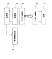
- a preferred embodiment of the wireless power transmission device of the present invention includes a pair of antennas 107 and 109 capable of transmitting power in a contactless manner by resonant magnetic field coupling at a frequency f0, and the pair of antennas.
- a control unit (frequency control unit) 100 that controls the transmission frequency according to the magnitude of power transmitted between the antennas 107 and 109 is provided.
- One of the pair of antennas is a series resonance circuit, and the other is a parallel resonance circuit.
- the control unit 100 sets the transmission frequency to a value within the first level range higher than the frequency f0, and the power is higher than the reference value P1.
- the transmission frequency When it is low, the transmission frequency is set to a value in the second level range lower than the first level range.
- This reference value P1 is a value set lower than the maximum transmission power Pmax, and can preferably be set in a range of 60% to 80% of the maximum transmission power Pmax.
- the present inventor When performing constant voltage operation in a wireless power transmission device that uses resonant magnetic field coupling, the present inventor combines resonant magnetic fields between transmitting and receiving antennas when sufficiently lower than the maximum transmission power Pmax, as will be described later. It has been found that transmission efficiency can be maintained high by switching modes. The present invention is based on this finding.
- the coupling mode can be switched by changing the transmission frequency according to whether the transmission frequency is higher or lower than the reference value P1.
- the 1A includes an oscillator 103 having an oscillation frequency f0.
- a frequency conversion circuit 161 may be connected to the subsequent stage of the power receiving antenna.
- the oscillator 103 receives direct-current or alternating-current energy (power) supplied from a power source (not shown), and frequency-converts the supplied energy into RF energy having a frequency ftr (DC / RF conversion or AC / RF conversion).
- this frequency ftr is called a transmission frequency.
- the RF energy output from the oscillator 103 is input to the power transmission antenna 107 connected to the oscillator 103.
- the power transmitting antenna 107 and the power receiving antenna 109 are a resonator pair designed in advance so that the respective resonance frequencies fT and fR are equal.
- the power transmitting antenna 107 and the power receiving antenna 109 are magnetically coupled via a resonant magnetic field formed by the mutual resonators in the peripheral space. As a result, the power receiving antenna 109 can efficiently receive at least a part of the RF energy transmitted by the power transmitting antenna 107 by the resonant magnetic field coupling.
- the control unit 100 generates a signal (for example, a variable frequency pulse train) for controlling the oscillation frequency of the oscillator 103 and inputs the signal to the oscillator 103.
- the output of the power receiving antenna 109 is connected to a load 111 as shown in FIG. 1B.
- the magnitude of the power to be transmitted from the power transmitting antenna 107 to the power receiving antenna 109 can change according to the state of the load 111 (for example, consumed power).
- information or a signal indicating the magnitude of transmission power required by the load 111 is given from the load 111 to the control unit 100.
- the control unit 100 can increase or decrease the oscillation frequency of the oscillator 103. As a result, the frequency of the transmission power is controlled.
- the oscillator 103 is connected to the power generation unit 102, and the frequency control unit 100 sets the transmission frequency of the oscillator 103 according to the situation of the power generation unit 102.
- the power generation unit 102 includes a power generation element such as a solar cell, for example.
- the power supplied from the power generation unit 102 to the oscillator 103 can change according to the state of the power generation unit 102.
- the electric power generated can change according to the amount of sunlight received by the solar cell.
- the magnitude of the power to be transmitted from the power transmission antenna 107 to the power reception antenna 109 can also change.
- FIG. 1C the oscillator 103 is connected to the power generation unit 102, and the frequency control unit 100 sets the transmission frequency of the oscillator 103 according to the situation of the power generation unit 102.
- the power generation unit 102 includes a power generation element such as a solar cell, for example.
- the power supplied from the power generation unit 102 to the oscillator 103 can change according to the state of the power generation
- the power generated by the power generation unit 102 that is, information or signal indicating the magnitude of transmission power is given from the power generation unit 102 to the control unit 100.
- the control unit 100 can increase or decrease the oscillation frequency of the oscillator 103. As a result, the frequency of the transmission power is controlled.
- the relationship between the magnitude of transmission power and the transmission frequency may be determined in advance based on experiments or the like and recorded in a wireless power transmission device or a memory provided in a load. Further, the relationship between the magnitude of transmission power and the transmission frequency may be determined based on transmission efficiency during actual power transmission.
- FIG. 1D is a graph showing an example of the relationship between the magnitude of transmission power and the frequency of transmission power.
- the first level range is higher than the frequency f0.
- the first level range is a range from the frequency f0 to the even mode resonance frequency fH
- the second level range is a range from the odd mode resonance frequency fL to the frequency f0.
- the even-mode and odd-mode resonance frequencies fH and fL will be described later.
- the transmission frequency is hopped between a value in the first level range and a value in the second level range.
- the control unit 100 switches the mode of the resonant magnetic field that couples the pair of antennas between the even mode and the odd mode.
- the transmission frequency can be set to a value equal to the frequency f0.
- the relationship between the magnitude of transmission power and the transmission frequency is not limited to the example of FIG. 1D.
- FIG. 1E shows an example of a more complex relationship.
- the control unit 100 sets the transmission frequency to a frequency f2 that is lower than the frequency f0. Set to the value of.
- the control part 100 sets a transmission frequency to a value higher than the frequency f2, when transmission power is lower than the 2nd reference value P2.
- the transmission frequency is preferably set to be approximately equal to the frequency f0.
- the relationship between the magnitude of transmission power and the transmission frequency, and the values such as the reference values P1, P2 are obtained by determining the transmission frequency that optimizes the transmission efficiency based on the given magnitude of transmission power.
- a specific example of the relationship between the magnitude of transmission power and the transmission frequency will be described in detail later.
- the coupling coefficient k of the pair of antennas is preferably maintained constant during power transmission.
- the power receiving antenna 109 is not in contact with the power transmitting antenna 107 and is separated from the power transmitting antenna 107 by, for example, several millimeters to several tens of centimeters.
- the frequency f0 is set to, for example, 50 Hz to 300 GHz, more preferably 20 kHz to 10 GHz, further preferably 20 kHz to 20 MHz, and further preferably 20 kHz to 1 MHz.
- the “antenna” in the wireless power transmission apparatus of the present invention is not a normal antenna for transmitting and receiving a radiated electromagnetic field, but uses two objects utilizing the coupling of the nearby components (evanescent tail) of the electromagnetic field of the resonator. It is an element for performing energy transfer between the two.
- energy loss radiation loss
- the energy transmission using the resonance electromagnetic field (near field) coupling not only has a small loss but also has a distance of, for example, several meters, compared to the known wireless power transmission using Faraday's law of electromagnetic induction. It becomes possible to transmit energy with high efficiency between two resonators (antennas).
- FIG. 3 is a diagram showing an equivalent circuit of an antenna pair in the wireless power transmission device of the present invention.
- the power transmission antenna 107 in the present invention is a series resonance circuit in which a first inductor 107a and a first capacitor element 107b are connected in series, and the power receiving antenna 109 is a second inductor 109a and a second capacitor element.
- 109b is a parallel resonant circuit connected in parallel.
- the series resonance circuit of the power transmission antenna 107 has a parasitic resistance component R1
- the parallel resonance circuit of the power reception antenna 109 has a parasitic resistance component R2.
- the power transmitting antenna and the power receiving antenna are configured by an asymmetric combination of a series resonant circuit and a parallel resonant circuit. That is, as shown in FIG. 4, even if the power transmitting antenna 107 is a parallel resonant circuit and the power receiving antenna 109 is a series resonant circuit, the same effect is exhibited.
- the transmission frequency ftr in the wireless power transmission apparatus of the present invention is variably controlled within a range larger than the frequency fL and smaller than fH according to the amount of power transmitted. Specifically, in the power transmission range from predetermined power (P1) to Pmax, high-efficiency transmission can be realized by transmitting power in a frequency band in which contribution from even-mode resonance is large.
- the transmission power range in which the transmission power is set lower than the predetermined power (P1) high-efficiency transmission can be realized by transmitting power in a frequency band in which contribution from odd mode resonance is large. That is, assuming that the transmission power is P, f0 ⁇ ftr ⁇ fH in the range of P1 ⁇ P ⁇ Pmax, and fL ⁇ ftr ⁇ f0 in P ⁇ P1.
- the optimum ftr (P ⁇ P1) under the transmission power condition near P1 is more than the optimum ftr (P ⁇ Pmax) under the transmission power condition near Pmax.
- the optimum ftr (P ⁇ P1) under the transmission power condition in the vicinity of P1 is set to a value lower than the optimum ftr (P ⁇ 0) under the extremely low power transmission condition. That is, in a preferred embodiment of the present invention, discontinuity occurs in the value of ftr set in the range of P ⁇ P1 and P ⁇ P1.
- even mode resonance is used under low impedance transmission conditions and odd mode resonance is used under high impedance transmission conditions.
- the transmission / reception antenna is configured by a combination of an asymmetric resonance circuit structure of a series resonance circuit and a parallel resonance circuit. That is, when both the transmitting and receiving antennas are constituted by a series resonant circuit pair or a parallel resonant circuit pair, the effect of the present invention is not exhibited. In addition, the effects of the present invention do not appear even when both the transmitting and receiving antennas have a circuit configuration (electromagnetic induction feeding type and described below) that receives energy feeding from an external circuit using the electromagnetic induction principle. Further, the effect of the present invention is not exhibited even in a resonator combination of a hybrid combination of a series resonance circuit and an electromagnetic induction power supply type, and a parallel resonance circuit and an electromagnetic induction power supply type.
- the value of P1 can be set to a power value of about 60% to 80% of Pmax, for example.
- the value of P1 is not limited to this range, and may be out of the above range depending on the situation.
- variable control of the transmission frequency can be easily realized by controlling the oscillation frequency of the oscillator 103.
- the coupling coefficient k between the transmitting antenna and the receiving antenna is maintained almost constant. This is because if the coupling coefficient k fluctuates greatly during power transmission, it is difficult to realize constant voltage operation with high efficiency.
- an amplifier capable of realizing a highly efficient and low distortion characteristic such as a class D, a class E, or a class F can be used, or a Doherty amplifier may be used.
- a sine wave may be generated with high efficiency by disposing a low-pass filter or a band-pass filter downstream of the switching element that generates an output signal including a distortion component.
- a frequency conversion circuit that performs high-frequency output from an AC input may be used. In any case, the electric power input to the oscillator is converted into RF energy. This RF energy is transmitted in a non-contact manner through a space by the wireless transmission unit, and is output from the output terminal.
- the output impedance of the RF energy output from the oscillator 103 in a state where the output terminal of the power receiving antenna 109 is connected to a load It is preferable to make the dance Zoc and the input impedance Zin of the power transmission antenna 107 equal. Similarly, it is preferable that the output impedance Zout of the power receiving antenna is equal to the resistance value R of the connected load in a state where the oscillator 103 is connected to the power transmitting antenna 107.
- equal of two impedances is not limited to the case where the impedances are exactly the same, and includes the case where the difference between the two impedances is 25% or less of the larger impedance. Define.
- the efficiency of wireless power transmission in the present embodiment depends on the distance between the power transmitting antenna 107 and the power receiving antenna 109 (antenna spacing) and the magnitude of loss of the circuit elements constituting the power transmitting antenna 107 and the power receiving antenna 109.
- the “antenna interval” is substantially the interval between the two inductors 107a and 109a.
- the antenna interval can be evaluated based on the size of the antenna arrangement area.
- the first inductor 107a and the second inductor 109a are both formed in a planar shape as shown in the schematic perspective view of FIG.
- the outer shape of the inductor can be arbitrarily selected. That is, not only squares and circles but also rectangles and ellipses can be selected.
- the size of the antenna arrangement area means the size of the antenna arrangement area having a relatively small size.
- the outer shape of the inductor constituting the antenna is a circle, the diameter of the inductor is used. In the case of a rectangle, the length is the short side of the inductor.
- the first inductor 107a and the second inductor 109a in the present embodiment have a spiral structure with the number of turns N1 and N2, respectively (N1> 1, N2> 1), but have a loop structure with the number of turns 1. May be.
- These inductors 107a and 109a do not need to be composed of a single conductor pattern, and may have a structure in which a plurality of laminated conductor patterns are connected in series.
- the first inductor 107a and the second inductor 109a can be suitably formed from a conductor such as copper or silver having good conductivity. Since the high-frequency current of RF energy flows in a concentrated manner on the surface of the conductor, the surface of the conductor may be covered with a high conductivity material in order to increase power generation efficiency. If the inductors 107a and 109a are formed from a configuration having a cavity in the center of the cross section of the conductor, weight reduction can be realized. Furthermore, if the inductors 107a and 109a are formed using a parallel wiring structure such as a litz wire, the conductor loss per unit length can be reduced, so that the Q value of the series resonant circuit and the parallel resonant circuit can be improved. This enables power transmission with higher efficiency.
- a conductor such as copper or silver having good conductivity. Since the high-frequency current of RF energy flows in a concentrated manner on the surface of the conductor, the surface of the conductor may be covered with a high
- a magnetic material may be disposed around the first inductor 107a and / or the second inductor 109a. It is more preferable to use an inductor having an air-core spiral structure that can set the coupling coefficient between the inductors 107a and 109a to an appropriate value.
- any type of capacitor having, for example, a chip shape or a lead shape can be used for the first and second capacitor elements 107b and 109b. It is also possible to cause the capacitance between the two wirings via air to function as the first and second capacitor elements 107b and 109b.
- the first and second capacitor elements 107b and 109b are formed of MIM capacitors, a low-loss capacitor circuit can be formed using a known semiconductor process or multilayer substrate process.
- the Q value of the resonator constituting each of the power transmitting antenna 107 and the power receiving antenna 109 depends on the transmission efficiency of the inter-antenna power transmission required by the system and the value of the coupling coefficient k, but is preferably 100 or more, more preferably Is set to 200 or more, more preferably 500 or more, and still more preferably 1000 or more. In order to achieve a high Q value, it is effective to use a litz wire as described above.
- the power transmission antenna and the power reception antenna were designed so that both resonance frequencies were 0.55 MHz.
- the power transmission antenna was manufactured by connecting a first inductor having an inductance of 3.67 ⁇ H and a first capacitor element having a capacitance of 4100 pF in series.
- the power receiving antenna was manufactured by connecting a second inductor having an inductance of 3.67 ⁇ H and a second capacitor element having a capacitance of 4100 pF in parallel.
- Both the first and second inductors were realized by litz wires that were configured by arranging 120 parallel copper wires each having a diameter of 75 ⁇ m and arranging them in parallel.
- the outer shapes of the two inductors were both 20 cm in diameter and the number of turns was set to 8.
- the unloaded Q value of the power transmission antenna (resonator) was 450.
- the power transmitting antenna and the power receiving antenna were disposed so that their formation surfaces face each other in parallel, and the distance g between the opposing surfaces was 10 cm.
- the manufactured resonator had a resonance frequency of 544.6 kHz, a coupling coefficient k between the transmitting and receiving antennas of 0.263, an odd mode resonance frequency of 481.7 kHz, and an even mode resonance frequency of 632 kHz.
- the RF input terminal of the power transmission antenna and the RF output terminal of the power reception antenna were connected to a network analyzer, and the high frequency transmission characteristics between the two terminals were measured.
- the optimum input / output impedances Zin and Zout that maximize the wireless transmission efficiency between the resonators were derived.
- the derivation was performed by the following two-step procedure. First, the high frequency characteristics between the input and output terminals of two antennas (resonators) were measured with a network analyzer having a terminal impedance of 50 ⁇ , and measurement data having 50 ⁇ as a reference impedance were obtained.
- the impedance conditions Zin and Zout and the transmission frequency ftr of the input / output terminals that minimize the signal reflection at the terminal and maximize the transmission power were derived on a circuit simulator.
- the peak frequency for realizing the maximum transmission efficiency ⁇ (P) was derived on the circuit simulator under the condition where the transmission power was increased or decreased.
- Zin and Zout are inversely proportional to the transmission power that increases or decreases in order to maintain constant voltage operation conditions. In this way, the peak frequency optimized according to the transmission power is obtained.
- the transmission frequency ftr (P) coincide with this peak frequency, it is possible to maintain high transmission efficiency even if the transmission power increases or decreases.
- FIG. 6 is a graph showing the transmission power dependence of the derived ⁇ (P).
- the vertical axis of the graph is the maximum transmission efficiency ⁇ , and the horizontal axis is the transmission power.
- Example 1 P1 corresponds to 74.5% with respect to Pmax.
- the effect of the present example is particularly apparent in the region of P ⁇ Pmax ⁇ 60%.
- FIG. 7 is a graph showing the transmission power dependence of the derived peak frequency (corresponding to ftr (P)).
- P ⁇ P1, f0 ⁇ ftr (P) ⁇ fH ( 632 kHz).
- 526.1 kHz ⁇ ftr (P) ⁇ 578.3 kHz.
- the fluctuation amount (Rhigh (ftrmax ⁇ f0) ⁇ (fH ⁇ f0) ⁇ 100) from the maximum value of ftr (P) to the natural frequency with respect to the fluctuation amount from the natural frequency of the even mode resonance frequency is 38.6. %Met.
- Embodiments 2 to 6 have the same basic configuration as Embodiment 1, but have a different coupling coefficient k. This is because the coupling coefficient k depends on the distance between the transmitting and receiving antennas.
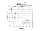
- FIG. 8 is a graph showing the transmission power dependence of the wireless unit maximum transmission efficiency for Example 5. As can be seen from FIG. 8, even in the case of Example 5, high transmission efficiency can be maintained in a region where transmission power is low.
- the power transmitting antenna was configured as a parallel resonant circuit
- the power receiving antenna was configured as a series resonant circuit.
- Example 1 In Example 1, the resonance circuit configuration of the power transmission side antenna and the power reception side antenna is asymmetric, but Comparative Examples 1 and 2 in which the transmission and reception antennas are symmetrical resonance circuit configurations were produced.
- the transmitting and receiving antennas are both configured as a series resonant circuit
- Comparative Example 2 both the transmitting and receiving antennas are configured as a parallel resonant circuit.
- the same examination as in Examples 1 to 6 was performed, and the maximum transmission efficiency at each transmission power during the constant voltage operation and the peak frequency for realizing the maximum transmission efficiency were derived.
- FIG. 9 showing the transmission power dependence of the transmission efficiency of Comparative Example 1, the transmission efficiency of Comparative Example 1 was hardly improved in the low power transmission region.
- the peak frequency of Comparative Example 1 is a value that greatly exceeds the even-mode resonance frequency of 632 kHz as the power transmission region moves toward the low power side. I didn't follow the conditions. Similarly, as apparent from FIGS. 11 and 12 showing the transmission efficiency and the transmission frequency dependence of the peak frequency in Comparative Example 2, the effect of the present invention was not exhibited in Comparative Example 2 as well.
- a signal is fed from an external circuit to the transmission / reception antenna by directly connecting a measurement high-frequency input / output terminal to the transmission / reception antenna.
- signal feeding from the external circuit to the transmission / reception antenna was performed using the electromagnetic induction principle. Specifically, a non-resonant coil having a diameter of 20 cm and a winding number of 6 facing each other 3 mm away from the transmitting and receiving antennas was used, the non-resonant coil was excited from an external circuit, and the transmitting and receiving antennas were excited from the non-resonant coil in a non-contact manner .
- Comparative Examples 4 and 5 In Comparative Examples 4 and 5, direct connection type power supply was performed on one of the transmission and reception antennas, and electromagnetic induction power supply was performed on the other.
- the direct connection type power feeding was performed under the same conditions as in Examples 1-6. Further, the electromagnetic induction power feeding was performed under the same conditions as in Comparative Example 3.
- Table 2 shows a circuit configuration comparison between Example 1 and Comparative Examples 1 to 5.
- Comparative Examples 4 and 5 the same study as in Examples 1 to 6 was performed, and the maximum transmission efficiency at each transmission power during constant voltage operation and the peak frequency for realizing the maximum transmission efficiency were derived.
- the peak frequency of Comparative Example 4 shows a tendency to increase as the power transmission region moves toward the low power side, and does not follow the frequency control condition of the present invention.
- Comparative Example 5 also did not comply with the frequency control conditions of the present invention.
- the wireless power transmission device of the present invention can be applied to a power feeding system for various devices such as AV appliance white goods that can operate by receiving energy supply from a power supply circuit that supplies a constant voltage.
- AV equipment includes, for example, a television
- white goods include, for example, a washing machine, a refrigerator, and an air conditioner.
- the wireless power transmission device of the present invention can also be applied as a charging system for electronic devices using rechargeable batteries, electric bikes, electric assist bicycles, and electric vehicles. This is because charging control at a constant voltage may be required as one of charging control for a rechargeable battery such as a lithium ion battery.
- the system of the present invention can be applied to all electronic devices with a motor driven at a constant voltage.
- the wireless power transmission device of the present invention can also be applied to a system that collects the power generated by the solar power generation device.
Landscapes
- Engineering & Computer Science (AREA)
- Computer Networks & Wireless Communication (AREA)
- Power Engineering (AREA)
- Near-Field Transmission Systems (AREA)
- Charge And Discharge Circuits For Batteries Or The Like (AREA)
Abstract
Priority Applications (3)
| Application Number | Priority Date | Filing Date | Title |
|---|---|---|---|
| EP12773195.8A EP2704291B1 (fr) | 2011-04-26 | 2012-04-24 | Dispositif de transmission d'énergie sans fil |
| JP2012541675A JP5172050B2 (ja) | 2011-04-26 | 2012-04-24 | 無線電力伝送装置 |
| CN201280001216.9A CN102918748B (zh) | 2011-04-26 | 2012-04-24 | 无线电力传输装置 |
Applications Claiming Priority (2)
| Application Number | Priority Date | Filing Date | Title |
|---|---|---|---|
| US201161479142P | 2011-04-26 | 2011-04-26 | |
| US61/479,142 | 2011-04-26 |
Publications (1)
| Publication Number | Publication Date |
|---|---|
| WO2012147339A1 true WO2012147339A1 (fr) | 2012-11-01 |
Family
ID=47067352
Family Applications (1)
| Application Number | Title | Priority Date | Filing Date |
|---|---|---|---|
| PCT/JP2012/002816 WO2012147339A1 (fr) | 2011-04-26 | 2012-04-24 | Dispositif de transmission d'énergie sans fil |
Country Status (5)
| Country | Link |
|---|---|
| US (2) | US9620995B2 (fr) |
| EP (2) | EP3093949B1 (fr) |
| JP (1) | JP5172050B2 (fr) |
| CN (1) | CN102918748B (fr) |
| WO (1) | WO2012147339A1 (fr) |
Cited By (3)
| Publication number | Priority date | Publication date | Assignee | Title |
|---|---|---|---|---|
| WO2013080530A1 (fr) * | 2011-11-29 | 2013-06-06 | パナソニック株式会社 | Dispositif de transmission d'énergie sans fil |
| WO2014068992A1 (fr) * | 2012-11-02 | 2014-05-08 | パナソニック株式会社 | Système de transmission de puissance sans fil |
| JP2018093730A (ja) * | 2013-12-19 | 2018-06-14 | パナソニックIpマネジメント株式会社 | 無線電力伝送のための送電装置および受電装置ならびに無線電力伝送システム |
Families Citing this family (18)
| Publication number | Priority date | Publication date | Assignee | Title |
|---|---|---|---|---|
| US11979201B2 (en) * | 2008-07-02 | 2024-05-07 | Powermat Technologies Ltd. | System and method for coded communication signals regulating inductive power transmissions |
| KR101212484B1 (ko) * | 2011-10-11 | 2012-12-14 | 주식회사 비앤알테크널러지 | 이동통신 단말기용 무선전력 충전장치 및 그 방법 |
| JP6242311B2 (ja) | 2013-10-29 | 2017-12-06 | パナソニック株式会社 | 無線送電装置及び無線電力伝送システム |
| CN105226843B (zh) * | 2014-05-27 | 2017-09-15 | 松下知识产权经营株式会社 | 无线电力传输系统以及无线电力传输系统的送电装置 |
| JP6359924B2 (ja) * | 2014-09-17 | 2018-07-18 | トヨタ自動車株式会社 | 非接触送受電システム |
| CN105958602A (zh) * | 2016-06-30 | 2016-09-21 | 庄景阳 | 电视机的无线供电装置 |
| CN106060667A (zh) * | 2016-06-30 | 2016-10-26 | 庄景阳 | 一种电视机的控制模块 |
| CN105978167A (zh) * | 2016-06-30 | 2016-09-28 | 庄景阳 | 蒸脸器的无线供电方法 |
| CN105914898A (zh) * | 2016-06-30 | 2016-08-31 | 庄景阳 | 扫路车的无线供电方法 |
| CN106100144A (zh) * | 2016-06-30 | 2016-11-09 | 泉州市中研智能机电研究院有限公司 | 基于无线供电的增流计划 |
| CN105933629A (zh) * | 2016-06-30 | 2016-09-07 | 庄景阳 | 一种电视机的无线供电方法 |
| CN105932784A (zh) * | 2016-06-30 | 2016-09-07 | 庄景阳 | 用于无人机的不同工况的初级线圈震荡频率控制方法 |
| CN106130192A (zh) * | 2016-06-30 | 2016-11-16 | 庄景阳 | 用于玩具车的不同工况的初级线圈震荡频率控制方法 |
| CN106120613A (zh) * | 2016-06-30 | 2016-11-16 | 庄景阳 | 扫路车的控制模块 |
| CN105898165A (zh) * | 2016-06-30 | 2016-08-24 | 庄景阳 | 用于电视机的不同工况的初级线圈震荡频率控制方法 |
| CN105958601A (zh) * | 2016-06-30 | 2016-09-21 | 庄景阳 | 蒸脸器的控制模块 |
| CN105957327A (zh) * | 2016-06-30 | 2016-09-21 | 庄景阳 | 无人机的控制模块 |
| CN106026412A (zh) * | 2016-06-30 | 2016-10-12 | 庄景阳 | 无人机的无线供电方法 |
Citations (4)
| Publication number | Priority date | Publication date | Assignee | Title |
|---|---|---|---|---|
| JP2008263710A (ja) * | 2007-04-11 | 2008-10-30 | Olympus Corp | 無線給電システム |
| US20080278264A1 (en) | 2005-07-12 | 2008-11-13 | Aristeidis Karalis | Wireless energy transfer |
| JP2011147213A (ja) * | 2010-01-12 | 2011-07-28 | Toyota Motor Corp | 電力伝送システムおよび車両用給電装置 |
| JP2011229360A (ja) * | 2010-03-31 | 2011-11-10 | Nissan Motor Co Ltd | 非接触給電装置及び非接触給電方法 |
Family Cites Families (13)
| Publication number | Priority date | Publication date | Assignee | Title |
|---|---|---|---|---|
| US5768112A (en) * | 1997-05-30 | 1998-06-16 | Delco Electronics Corp. | Sub-resonant series resonant converter having improved form factor and reduced EMI |
| US6160374A (en) * | 1999-08-02 | 2000-12-12 | General Motors Corporation | Power-factor-corrected single-stage inductive charger |
| CA2718901C (fr) | 2008-03-17 | 2018-10-16 | Powermat Ltd. | Systeme de transmission inductif |
| JP2009268181A (ja) | 2008-04-22 | 2009-11-12 | Olympus Corp | エネルギー供給装置 |
| JP5106237B2 (ja) | 2008-05-02 | 2012-12-26 | オリンパス株式会社 | 無線給電システム |
| ES2326780B2 (es) | 2008-05-29 | 2010-06-16 | Fundacion Circe - Centro De Investigacion De Recursos Y Consumos Energeticos | Metodo automatico de control de un sistema de transferencia de potencia con acoplamiento inductivo en alta frecuencia. |
| CN104539027A (zh) * | 2008-07-09 | 2015-04-22 | 捷通国际有限公司 | 无线充电系统 |
| US8278784B2 (en) * | 2008-07-28 | 2012-10-02 | Qualcomm Incorporated | Wireless power transmission for electronic devices |
| US8446045B2 (en) * | 2008-08-20 | 2013-05-21 | Intel Corporation | Flat, asymmetric, and E-field confined wireless power transfer apparatus and method thereof |
| US20100081379A1 (en) * | 2008-08-20 | 2010-04-01 | Intel Corporation | Wirelessly powered speaker |
| JP2010136464A (ja) | 2008-12-02 | 2010-06-17 | Casio Computer Co Ltd | 電力伝送装置および電力伝送方法 |
| JP4849142B2 (ja) | 2009-02-27 | 2012-01-11 | ソニー株式会社 | 電力供給装置および電力伝送システム |
| JP5681947B2 (ja) | 2009-08-13 | 2015-03-11 | パナソニックIpマネジメント株式会社 | 無線電力伝送装置、ならびに無線電力伝送装置を備える発電装置および発電システム |
-
2012
- 2012-04-23 US US13/453,045 patent/US9620995B2/en active Active
- 2012-04-24 WO PCT/JP2012/002816 patent/WO2012147339A1/fr active Application Filing
- 2012-04-24 EP EP16175213.4A patent/EP3093949B1/fr active Active
- 2012-04-24 JP JP2012541675A patent/JP5172050B2/ja active Active
- 2012-04-24 EP EP12773195.8A patent/EP2704291B1/fr active Active
- 2012-04-24 CN CN201280001216.9A patent/CN102918748B/zh active Active
-
2017
- 2017-02-22 US US15/439,047 patent/US10103581B2/en active Active
Patent Citations (4)
| Publication number | Priority date | Publication date | Assignee | Title |
|---|---|---|---|---|
| US20080278264A1 (en) | 2005-07-12 | 2008-11-13 | Aristeidis Karalis | Wireless energy transfer |
| JP2008263710A (ja) * | 2007-04-11 | 2008-10-30 | Olympus Corp | 無線給電システム |
| JP2011147213A (ja) * | 2010-01-12 | 2011-07-28 | Toyota Motor Corp | 電力伝送システムおよび車両用給電装置 |
| JP2011229360A (ja) * | 2010-03-31 | 2011-11-10 | Nissan Motor Co Ltd | 非接触給電装置及び非接触給電方法 |
Non-Patent Citations (1)
| Title |
|---|
| See also references of EP2704291A4 |
Cited By (9)
| Publication number | Priority date | Publication date | Assignee | Title |
|---|---|---|---|---|
| WO2013080530A1 (fr) * | 2011-11-29 | 2013-06-06 | パナソニック株式会社 | Dispositif de transmission d'énergie sans fil |
| JPWO2013080530A1 (ja) * | 2011-11-29 | 2015-04-27 | パナソニックIpマネジメント株式会社 | 無線電力伝送装置 |
| US9197101B2 (en) | 2011-11-29 | 2015-11-24 | Panasonic Intellectual Property Management Co., Ltd. | Wireless electric power transmission apparatus |
| WO2014068992A1 (fr) * | 2012-11-02 | 2014-05-08 | パナソニック株式会社 | Système de transmission de puissance sans fil |
| JPWO2014068992A1 (ja) * | 2012-11-02 | 2016-09-08 | パナソニックIpマネジメント株式会社 | 無線電力伝送システム |
| US9768643B2 (en) | 2012-11-02 | 2017-09-19 | Panasonic Intellectual Property Management Co., Ltd. | Wireless power transmission system capable of continuing power transmission while suppressing heatup of foreign objects |
| US9997961B2 (en) | 2012-11-02 | 2018-06-12 | Panasonic Intellectual Property Management Co., Ltd. | Wireless power transmission system capable of continuing power transmission while suppressing heatup of foreign objects |
| US10250082B2 (en) | 2012-11-02 | 2019-04-02 | Panasonic Intellectual Property Management Co., Ltd. | Wireless power transmission system capable of continuing power transmission while suppressing heatup of foreign objects |
| JP2018093730A (ja) * | 2013-12-19 | 2018-06-14 | パナソニックIpマネジメント株式会社 | 無線電力伝送のための送電装置および受電装置ならびに無線電力伝送システム |
Also Published As
| Publication number | Publication date |
|---|---|
| EP3093949A1 (fr) | 2016-11-16 |
| EP2704291A1 (fr) | 2014-03-05 |
| JP5172050B2 (ja) | 2013-03-27 |
| US9620995B2 (en) | 2017-04-11 |
| JPWO2012147339A1 (ja) | 2014-07-28 |
| US20170163099A1 (en) | 2017-06-08 |
| EP2704291B1 (fr) | 2016-08-03 |
| US20120274149A1 (en) | 2012-11-01 |
| CN102918748B (zh) | 2016-02-03 |
| EP3093949B1 (fr) | 2018-02-28 |
| CN102918748A (zh) | 2013-02-06 |
| EP2704291A4 (fr) | 2015-07-29 |
| US10103581B2 (en) | 2018-10-16 |
Similar Documents
| Publication | Publication Date | Title |
|---|---|---|
| JP5172050B2 (ja) | 無線電力伝送装置 | |
| JP6172607B2 (ja) | 無線電力伝送装置 | |
| JP5934934B2 (ja) | 無線電力伝送システム | |
| JP6288519B2 (ja) | 無線電力伝送システム | |
| JP2016039773A (ja) | 送電装置および無線電力伝送システム | |
| JP6108310B2 (ja) | 無線電力伝送装置 | |
| JP6094820B2 (ja) | 無線電力伝送装置 | |
| JP2015220891A (ja) | 共振器及び無線給電システム | |
| JP2013021862A (ja) | 給電システムの設計方法 | |
| JP2012023297A (ja) | 共鳴コイル |
Legal Events
| Date | Code | Title | Description |
|---|---|---|---|
| WWE | Wipo information: entry into national phase |
Ref document number: 201280001216.9 Country of ref document: CN |
|
| ENP | Entry into the national phase |
Ref document number: 2012541675 Country of ref document: JP Kind code of ref document: A |
|
| REEP | Request for entry into the european phase |
Ref document number: 2012773195 Country of ref document: EP |
|
| WWE | Wipo information: entry into national phase |
Ref document number: 2012773195 Country of ref document: EP |
|
| 121 | Ep: the epo has been informed by wipo that ep was designated in this application |
Ref document number: 12773195 Country of ref document: EP Kind code of ref document: A1 |
|
| NENP | Non-entry into the national phase |
Ref country code: DE |