WO2012147251A1 - 原料の気化供給装置 - Google Patents
原料の気化供給装置 Download PDFInfo
- Publication number
- WO2012147251A1 WO2012147251A1 PCT/JP2012/001117 JP2012001117W WO2012147251A1 WO 2012147251 A1 WO2012147251 A1 WO 2012147251A1 JP 2012001117 W JP2012001117 W JP 2012001117W WO 2012147251 A1 WO2012147251 A1 WO 2012147251A1
- Authority
- WO
- WIPO (PCT)
- Prior art keywords
- pressure
- flow rate
- raw material
- source tank
- mixed gas
- Prior art date
- Legal status (The legal status is an assumption and is not a legal conclusion. Google has not performed a legal analysis and makes no representation as to the accuracy of the status listed.)
- Ceased
Links
Images




Classifications
-
- C—CHEMISTRY; METALLURGY
- C23—COATING METALLIC MATERIAL; COATING MATERIAL WITH METALLIC MATERIAL; CHEMICAL SURFACE TREATMENT; DIFFUSION TREATMENT OF METALLIC MATERIAL; COATING BY VACUUM EVAPORATION, BY SPUTTERING, BY ION IMPLANTATION OR BY CHEMICAL VAPOUR DEPOSITION, IN GENERAL; INHIBITING CORROSION OF METALLIC MATERIAL OR INCRUSTATION IN GENERAL
- C23C—COATING METALLIC MATERIAL; COATING MATERIAL WITH METALLIC MATERIAL; SURFACE TREATMENT OF METALLIC MATERIAL BY DIFFUSION INTO THE SURFACE, BY CHEMICAL CONVERSION OR SUBSTITUTION; COATING BY VACUUM EVAPORATION, BY SPUTTERING, BY ION IMPLANTATION OR BY CHEMICAL VAPOUR DEPOSITION, IN GENERAL
- C23C16/00—Chemical coating by decomposition of gaseous compounds, without leaving reaction products of surface material in the coating, i.e. chemical vapour deposition [CVD] processes
- C23C16/44—Chemical coating by decomposition of gaseous compounds, without leaving reaction products of surface material in the coating, i.e. chemical vapour deposition [CVD] processes characterised by the method of coating
- C23C16/448—Chemical coating by decomposition of gaseous compounds, without leaving reaction products of surface material in the coating, i.e. chemical vapour deposition [CVD] processes characterised by the method of coating characterised by the method used for generating reactive gas streams, e.g. by evaporation or sublimation of precursor materials
- C23C16/4481—Chemical coating by decomposition of gaseous compounds, without leaving reaction products of surface material in the coating, i.e. chemical vapour deposition [CVD] processes characterised by the method of coating characterised by the method used for generating reactive gas streams, e.g. by evaporation or sublimation of precursor materials by evaporation using carrier gas in contact with the source material
-
- C—CHEMISTRY; METALLURGY
- C23—COATING METALLIC MATERIAL; COATING MATERIAL WITH METALLIC MATERIAL; CHEMICAL SURFACE TREATMENT; DIFFUSION TREATMENT OF METALLIC MATERIAL; COATING BY VACUUM EVAPORATION, BY SPUTTERING, BY ION IMPLANTATION OR BY CHEMICAL VAPOUR DEPOSITION, IN GENERAL; INHIBITING CORROSION OF METALLIC MATERIAL OR INCRUSTATION IN GENERAL
- C23C—COATING METALLIC MATERIAL; COATING MATERIAL WITH METALLIC MATERIAL; SURFACE TREATMENT OF METALLIC MATERIAL BY DIFFUSION INTO THE SURFACE, BY CHEMICAL CONVERSION OR SUBSTITUTION; COATING BY VACUUM EVAPORATION, BY SPUTTERING, BY ION IMPLANTATION OR BY CHEMICAL VAPOUR DEPOSITION, IN GENERAL
- C23C16/00—Chemical coating by decomposition of gaseous compounds, without leaving reaction products of surface material in the coating, i.e. chemical vapour deposition [CVD] processes
- C23C16/44—Chemical coating by decomposition of gaseous compounds, without leaving reaction products of surface material in the coating, i.e. chemical vapour deposition [CVD] processes characterised by the method of coating
- C23C16/455—Chemical coating by decomposition of gaseous compounds, without leaving reaction products of surface material in the coating, i.e. chemical vapour deposition [CVD] processes characterised by the method of coating characterised by the method used for introducing gases into reaction chamber or for modifying gas flows in reaction chamber
- C23C16/45512—Premixing before introduction in the reaction chamber
-
- C—CHEMISTRY; METALLURGY
- C23—COATING METALLIC MATERIAL; COATING MATERIAL WITH METALLIC MATERIAL; CHEMICAL SURFACE TREATMENT; DIFFUSION TREATMENT OF METALLIC MATERIAL; COATING BY VACUUM EVAPORATION, BY SPUTTERING, BY ION IMPLANTATION OR BY CHEMICAL VAPOUR DEPOSITION, IN GENERAL; INHIBITING CORROSION OF METALLIC MATERIAL OR INCRUSTATION IN GENERAL
- C23C—COATING METALLIC MATERIAL; COATING MATERIAL WITH METALLIC MATERIAL; SURFACE TREATMENT OF METALLIC MATERIAL BY DIFFUSION INTO THE SURFACE, BY CHEMICAL CONVERSION OR SUBSTITUTION; COATING BY VACUUM EVAPORATION, BY SPUTTERING, BY ION IMPLANTATION OR BY CHEMICAL VAPOUR DEPOSITION, IN GENERAL
- C23C16/00—Chemical coating by decomposition of gaseous compounds, without leaving reaction products of surface material in the coating, i.e. chemical vapour deposition [CVD] processes
- C23C16/44—Chemical coating by decomposition of gaseous compounds, without leaving reaction products of surface material in the coating, i.e. chemical vapour deposition [CVD] processes characterised by the method of coating
- C23C16/455—Chemical coating by decomposition of gaseous compounds, without leaving reaction products of surface material in the coating, i.e. chemical vapour deposition [CVD] processes characterised by the method of coating characterised by the method used for introducing gases into reaction chamber or for modifying gas flows in reaction chamber
- C23C16/45557—Pulsed pressure or control pressure
-
- C—CHEMISTRY; METALLURGY
- C23—COATING METALLIC MATERIAL; COATING MATERIAL WITH METALLIC MATERIAL; CHEMICAL SURFACE TREATMENT; DIFFUSION TREATMENT OF METALLIC MATERIAL; COATING BY VACUUM EVAPORATION, BY SPUTTERING, BY ION IMPLANTATION OR BY CHEMICAL VAPOUR DEPOSITION, IN GENERAL; INHIBITING CORROSION OF METALLIC MATERIAL OR INCRUSTATION IN GENERAL
- C23C—COATING METALLIC MATERIAL; COATING MATERIAL WITH METALLIC MATERIAL; SURFACE TREATMENT OF METALLIC MATERIAL BY DIFFUSION INTO THE SURFACE, BY CHEMICAL CONVERSION OR SUBSTITUTION; COATING BY VACUUM EVAPORATION, BY SPUTTERING, BY ION IMPLANTATION OR BY CHEMICAL VAPOUR DEPOSITION, IN GENERAL
- C23C16/00—Chemical coating by decomposition of gaseous compounds, without leaving reaction products of surface material in the coating, i.e. chemical vapour deposition [CVD] processes
- C23C16/44—Chemical coating by decomposition of gaseous compounds, without leaving reaction products of surface material in the coating, i.e. chemical vapour deposition [CVD] processes characterised by the method of coating
- C23C16/52—Controlling or regulating the coating process
-
- H—ELECTRICITY
- H10—SEMICONDUCTOR DEVICES; ELECTRIC SOLID-STATE DEVICES NOT OTHERWISE PROVIDED FOR
- H10P—GENERIC PROCESSES OR APPARATUS FOR THE MANUFACTURE OR TREATMENT OF DEVICES COVERED BY CLASS H10
- H10P72/00—Handling or holding of wafers, substrates or devices during manufacture or treatment thereof
- H10P72/04—Apparatus for manufacture or treatment
- H10P72/0402—Apparatus for fluid treatment
-
- Y—GENERAL TAGGING OF NEW TECHNOLOGICAL DEVELOPMENTS; GENERAL TAGGING OF CROSS-SECTIONAL TECHNOLOGIES SPANNING OVER SEVERAL SECTIONS OF THE IPC; TECHNICAL SUBJECTS COVERED BY FORMER USPC CROSS-REFERENCE ART COLLECTIONS [XRACs] AND DIGESTS
- Y10—TECHNICAL SUBJECTS COVERED BY FORMER USPC
- Y10T—TECHNICAL SUBJECTS COVERED BY FORMER US CLASSIFICATION
- Y10T137/00—Fluid handling
- Y10T137/7722—Line condition change responsive valves
- Y10T137/7837—Direct response valves [i.e., check valve type]
Definitions
- the present invention relates to an improvement of a raw material vaporization supply device of a semiconductor manufacturing apparatus using a so-called metal organic chemical vapor deposition method (hereinafter referred to as MOCVD method). Or, even if the raw material has a low vapor pressure, the raw material vapor of all raw materials can be supplied, and the internal pressure in the source tank can be adjusted to control the mixing ratio of the raw material vapor and the carrier gas.
- the present invention relates to a raw material vaporization supply apparatus that can efficiently manufacture a high-quality semiconductor by supplying a mixed gas whose flow rate is controlled to a set flow rate to a process chamber.
- the inventors of the present application have previously developed a raw material vaporization supply apparatus as shown in FIG. 6 as a raw material vaporization supply apparatus for a semiconductor manufacturing apparatus by the MOCVD method, and disclosed this (Japanese Patent No. 4605790).
- 1 is a carrier gas supply source
- 2 is a decompressor
- 3 is a thermal mass flow controller (mass flow controller)
- 4 is a liquid material such as raw material (Al (CH 3 ) 3 ), and Pb (dpm) 2 is a sublimation-type solid raw material)
- 5 is a source tank
- 6 is a constant temperature heating unit
- 7, 9 and 10 are valves
- 8 is an introduction pipe
- 11 is a process chamber
- 14 is a vacuum pump
- 15 is in a source tank
- 16 is an arithmetic control unit
- 17 is an input terminal for a set pressure signal
- 18 is an output terminal for a detected pressure signal
- G 1 is a carrier gas such as Ar
- G 4 is a saturated vapor of raw material
- Go is a carrier A mixed gas of the gas G 1 and the raw material vapor G 4
- Po is a pressure detector of the mixed gas Go
- To is a temperature detector of the mixed gas Go
- CV is a
- the pressure PG 1 of the carrier gas G 1 supplied into the source tank 5 is set to a predetermined pressure value by the decompression device 2, and the supply flow rate is the thermal mass flow control device. (Mass flow controller) 3 is set to a predetermined value.
- mass flow controller mass flow controller 3 is set to a predetermined value.
- the set value supply amount of the carrier gas G 1 is a thermal mass flow controller 3, also the temperature of the source tank 5 is set value, further the internal pressure of the source tank 5 (The pressure of the mixed gas Go) is maintained at the set value by the automatic pressure adjusting device 15, so that the mixed gas Go of a constant flow rate with a constant mixing ratio is set by the thermal mass flow control device 3 through the control valve CV. It is supplied to the process chamber 11 while being controlled to a predetermined flow rate value proportional to the flow rate with high accuracy.
- the source tank 5 and the control valve CV of the automatic pressure adjusting device 15 are heated and held at a high temperature of 150 ° C., the pressure of the saturated vapor G 4 of the raw material 4 in the source tank 5 is increased, and the process chamber 11 can sufficiently meet the demand for an increase in the amount of steam G 4 supplied to the 11 side and the temperature increase of the mixed gas Go, and more completely prevent condensation of the raw material saturated steam G 4 in the mixed gas Go supply line. Is done.
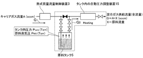
- the raw material flow rate X is the flow rate of the carrier gas A, the pressure of the source tank Ptank, determined by vapor pressure (partial pressure) P M o of the material, also, the internal pressure Ptank source tank Depending on the temperature in the source tank, the carry-out amount of the raw material due to the bubbles changes depending on the liquid level of the raw material in the tank.
- the concentration of the raw material in the mixed gas Go is determined by using the carrier gas flow rate A, the internal pressure Ptank of the source tank, the temperature t in the source tank, and the liquid level height of the raw material in the source tank (the raw material concentration in the bubbles) as parameters. Will be decided.
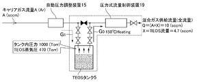
- FIG. 8 shows a vaporizing and supplying apparatus for the raw material shown in FIG. 6, in which the raw material is TEOS (tetraethoxysilane), the flow rate A of carrier gas (Ar) is 10 (sccm), and the internal pressure Ptank of the source tank is 1000 (Torr).
- the control pressure of the automatic pressure regulator 15), the TEOS vapor pressure 470 Torr (at 150 ° C.), the TEOS flow rate X (sccm), the TEOS flow rate X, the carrier gas flow rate A, and the This shows the correlation with the mixed gas supply flow rate (total flow rate Q A + X).
- the flow rate Q (total flow rate A + X) and the carrier gas flow rate A are different values, and the thermal mass flow controller 3 cannot directly control the flow rate of the mixed gas Go.
- the evaporation of the raw material in the source tank is promoted by constant temperature heating at a temperature of 250 ° C., and the pressure of the mixed gas Go of the carrier gas G 1 and the raw material vapor G 4 in the source tank 5 is further increased by an automatic pressure adjusting device.
- the Po is controlled to a predetermined value with high accuracy.
- the flow rate of the mixed gas Go flowing into the process chamber 11 and the mixing ratio of the carrier gas G 1 and the vapor G 4 in the mixed gas Go are always kept constant, and the process chamber 11 is always stably supplied to the process chamber. A desired amount of raw material 4 is supplied. As a result, there is an excellent effect that the quality of the manufactured semiconductor product can be greatly improved and defective products can be reduced.
- the second problem is the bubbling method, so that it is difficult to supply the raw material vapor stably in the case of a solid raw material, and it is difficult to supply the raw material vapor stably in the case of a low vapor pressure raw material. Therefore, there is a problem that the supply of the mixed gas to the process chamber tends to become unstable. That is, the raw materials that can be vaporized and supplied are limited, and there is a problem that vaporization and supply of all raw materials cannot be performed.
- the third problem is that the concentration of the raw material vapor in the mixed gas Go varies greatly due to the fluctuation of the raw material liquid level in the source tank, and it is difficult to control the concentration of the raw material vapor. That is, in the bubbling method, the raw material vapor adheres to or is contained in the bubbles while the bubble flow rises in the raw material liquid, and is taken out into the upper space inside the source tank. contact movement distance, i.e., the amount of raw material vapor G 4 which are brought by the liquid level of the raw material 4 into the upper interior space of the source tank 5 is to vary significantly, by variations in the height of the material liquid level That is, the concentration of the raw material in the mixed gas Go changes.
- the fourth problem is that the flow rate A of the carrier gas on the inlet side and the mixed gas flow rate (total flow rate) Q on the outlet side are different, so that it is difficult to control the mixed gas flow rate with high accuracy and the internal pressure of the source tank is high. Accurate control is not easy, and as a result, adjustment of the raw material concentration directly related to the partial pressure of the raw material vapor in the mixed gas in the tank is not easy. That is, since it is difficult to stably supply the mixed gas Go while keeping the raw material concentration constant, an expensive raw material concentration monitoring device is required, or the amount of raw material taken out from the source tank is calculated. However, there is a problem that it takes time to manage the remaining amount of raw material in the source tank.
- the present invention has the above-described problems in the raw material vaporization and supply apparatus of Japanese Patent No. 4605790, that is, it is difficult to reduce the manufacturing cost due to the use of the thermal mass flow controller, and the raw materials that can be vaporized and supplied are limited.
- the main object of the present invention is to solve the problems such as high accuracy flow rate control of the mixed gas supplied to the chamber and adjustment of the raw material concentration in the mixed gas.
- the manufacturing cost can be reduced easily, all the raw materials can be stably vaporized, and the flow rate of the mixed gas supplied to the chamber and the concentration of the raw material in the mixed gas can be controlled easily and with high accuracy. It provides a vaporized supply of raw materials.
- the invention of claim 1 includes a carrier gas supply source, a source tank storing raw materials, a flow path L 1 for supplying a carrier gas G 1 from the carrier gas supply source to an internal upper space of the source tank, and interposed in the flow path L 1, and the automatic pressure regulating device for controlling the pressure inside the upper space of the source tank set pressure, from said inner upper space of the source tank, the raw material vapor and the carrier gas generated from the raw material a flow path L 2 for supplying the mixed gas G 0 is a mixture to the process chamber with, interposed in the flow path L 2, to automatically adjust the flow rate of the mixed gas G 0 supplied to the process chamber in the setting flow rate a flow control device consists of a said source tank and the flow path L 1 and the flow path L 2 and a constant-temperature heating unit for heating the set temperature, while controlling the inner pressure of the inner upper space of the source tank to a desired pressure It is an basic configuration of the invention that the mixed gas G 0 to Rosesuchanba configured as supplied.
- the invention of claim 2 is the invention of claim 1, the flow path L 1 and the flow channel L 2, which was constituted by the inside of the flow path of the piping passage through which fluid flows, automatic pressure regulator and flow controller is there.
- an automatic pressure adjusting device for controlling the pressure in the upper space inside the source tank is provided with a control valve CV 1 and a temperature detector T 0 provided downstream thereof.
- the temperature of the pressure detector P 0 and the detected value of the pressure detector P 0 is corrected based on the detected value of the temperature detector T 0 to calculate the pressure of the carrier gas G 1. Comparing the calculation pressure with a calculation control unit that outputs a control signal Pd for controlling the opening and closing of the control valve CV 1 in a direction that reduces the difference between the two and a heater that heats the flow path through which the carrier gas flows to a predetermined temperature. It is a thing.
- the invention of claim 4 is the invention of claim 1, a flow control device for supplying to the process chamber mixed gas G 0 from the inner upper space of the source tank, the control valve CV 2, the temperature detection provided on the downstream side
- the flow rate of the mixed gas G 0 calculated using the detector T and the pressure detector P, the orifice provided on the downstream side of the pressure detector P, and the detected value of the pressure detector P is used as the detected value of the temperature detector T.
- the calculation control unit outputs a control signal Pd to be controlled, and a heater that heats the flow path through which the mixed gas flows to a predetermined temperature.
- the invention of claim 5 is the invention of claim 1, wherein the raw material is a solid raw material supported on a liquid or porous carrier.
- the temperature in the source tank is maintained at a set value
- the pressure in the upper space inside the source tank is controlled by an automatic pressure adjusting device
- the mixed gas is supplied from the space in the upper interior of the source tank.
- the flow rate is controlled by a pressure-type flow rate control device and supplied to the chamber.
- the vapor pressure PMo of the raw material vapor in the source tank is maintained at the saturated vapor at the set temperature by heating the raw material in the source tank, and since so as to control the set value total pressure Ptank by the automatic pressure regulating device, Aima' also be the raw material flow rate X in the mixed gas Go is directly proportional to the ratio of the raw material vapor pressure P M o and the tank internal pressure Ptank Thus, the raw material flow rate X can be easily controlled with high accuracy and stability.
- the flow rate controlled by the flow rate control device and the mixed gas flow rate Q have the same value, the flow rate control of the mixed gas Go can be performed with high accuracy, and furthermore, the raw material flow rate X can be easily calculated. It is possible to easily know the remaining amount of the raw material, and the management of the raw material is simplified.
- FIG. 1 is a configuration system diagram of a raw material vaporization supply apparatus according to an embodiment of the present invention.
- the raw material vaporization supply apparatus includes a carrier gas supply source 1, a source tank 5 containing the raw material 4, and a source tank 5.
- An automatic pressure adjustment device 15 that controls the internal pressure, a flow rate control device 19 that adjusts the supply flow rate of the mixed gas Go supplied to the process chamber 11, a flow path of the automatic pressure adjustment device 15 and the flow rate control device 19, the source tank 5, and the like. It is comprised from the constant temperature heating part 6 etc. which heat.
- FIG. 1 the same reference numerals are used for the same components as those of the raw material vaporizing and supplying apparatus shown in FIG. 6, and the same reference numerals are used for the source tank 5 in the conventional raw material vaporizing and supplying apparatus.
- an automatic pressure adjusting device 15 for adjusting the pressure in the internal upper space portion 5a of the source tank 5 is used, whereby the source tank 5 of points so as to control the internal pressure and the point which is adapted to supply directly to the carrier gas G 1 into the interior upper space portion 5a of the source tank 5 without bubbling, as well as mixed gas Go from the source tank 5
- the other components and members are the same as those shown in FIG. 6 except for the point that the mixed gas Go is supplied to the chamber 11 while the flow rate is controlled by the flow rate control device 19. Is the same as in the case of location.
- a carrier gas G 1 such as Ar supplied from a carrier gas supply source 1 is supplied to an internal upper space 5 a of a source tank 5 through a control valve CV 1 of an automatic pressure regulator 15.
- the internal pressure of the source tank 5 is controlled to a predetermined pressure value by the automatic pressure adjusting device 15.
- an appropriate amount of liquid raw material for example, an organic metal compound such as TEOS
- a solid raw material for example, a solid raw material in which an organic metal compound is supported on a porous support
- the source tank 5 Filled and heated to 150 ° C. to 250 ° C. by a heater (not shown) in the constant temperature heating unit 6, the saturated vapor G 4 of the raw material 4 at that heating temperature is generated, and the inside of the source tank 5 is The space 5a will be filled.
- the saturated vapor G 4 and carrier gas G 1 of the generated raw material 4, are mixed within the interior upper space portion 5a of the source tank 5, the mixed gas Go is the control valve CV 2 of the flow control device 19 through the valve 9 As will be described later, the mixed gas Go controlled to a predetermined flow rate by the flow rate control device 19 is supplied to the process chamber 11.
- the automatic pressure adjusting device 15 is provided on the downstream side of the carrier gas supply source 1 and is used for automatically adjusting the pressure in the internal upper space 5a of the source tank 5 to a set value. That is, the pressure Po and the temperature To of the carrier gas G 1 are detected in the flow path L 1 on the inflow side into the source tank 5, and the pressure temperature is detected in the arithmetic control unit 16 using the detected pressure Po and the temperature To. Correction is performed, and the corrected pressure value is compared with the set pressure value from the setting input terminal 17 to control the opening and closing of the control valve CV 1 in a direction in which the deviation between the two becomes zero.
- FIG. 2 shows a block configuration of the automatic pressure adjusting device 15.
- the arithmetic control unit 16 includes a temperature correction circuit 16a, a comparison circuit 16b, an input / output circuit 16c, an output circuit 16d, and the like.
- the detection values from the pressure detector Po and the temperature detector To are converted into digital signals and input to the temperature correction circuit 16a, where the detection pressure Po is corrected to the detection pressure Pt and then input to the comparison circuit 16b.
- the set pressure input signal Ps is input from the terminal 17, converted into a digital value by the input / output circuit 16c, and then input to the comparison circuit 16b, where the detected pressure Pt subjected to temperature correction from the temperature correction circuit 16a.
- the set pressure input signal Ps is when the detection is greater than the pressure Pt in which the temperature correction
- the control signal Pd is output to the drive unit of the control valve CV 1.
- the control valve CV 1 is driven in the valve opening direction, is driven in the valve opening direction until the difference between the set pressure input signal Ps and temperature corrected detected pressure Pt (Ps-Pt) becomes zero.
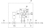
- the flow control device 19 is provided on the outlet flow path L 2 of the gas mixture Go on the downstream side of the source tank 5, as shown in diagram of Fig. 3, the orifices a mixed gas Go which has flowed through the control valve CV 2
- the rest of the configuration is the same as that of the automatic pressure adjusting device 19 except that the flow is made to flow out through 21. Therefore, detailed description thereof is omitted here.
- a so-called temperature correction is performed based on the detection value of the detector T, the flow rate calculation value after the temperature correction is compared with the set flow rate value by the comparison circuit 20b, and a difference signal between the two is output to the drive circuit of the control valve CV2. It has a configuration.
- the flow control device 19 itself is known as described above, but the downstream pressure P 2 of the orifice 21 (ie, the pressure P 2 on the process chamber side) and the upstream pressure P 1 of the orifice 21 (ie, the control valve CV 2).
- the downstream pressure P 2 of the orifice 21 ie, the pressure P 2 on the process chamber side
- the upstream pressure P 1 of the orifice 21 ie, the control valve CV 2
- the raw material flow rate X (that is, the raw material concentration in the mixed gas Go) is determined by the internal pressure Ptank of the source tank and the saturated vapor pressure P M o of the raw material.
- the temperature in the source tank is determined as a parameter.
- the carrier gas G 1 is argon (Ar)
- the following shows the main specifications of the automatic pressure adjusting device 15 for adjusting the internal pressure of the source tank used in this embodiment.
- the maximum operating temperature is 150 ° C. and the maximum pressure at the flow rate of 500 sccm (N 2 ) (F.F. S. pressure) is 133.3 kPaabs.
- the main specifications of the flow control device 19 used in this embodiment are as follows.
- the name column in Table 1 is the flow control device, the pressure range (FS pressure) column is the flow range (FS), The secondary pressure column only changes to 500 kPa abs or less at 500 sccm (N 2 ), and the other specifications are exactly the same.
- control valves CV 1 and CV 2 used in the automatic pressure adjusting device 15 and the flow rate control device 19 increase the operating temperature to 150 ° C. to 250 ° C., so that valve components such as piezo actuators and disc springs are used.
- valve components such as piezo actuators and disc springs.
- the storage case of the piezo element driving unit is a perforated chassis, and the piezo element driving unit and the like are structured to be air-cooled, thereby reducing the thermal expansion of each component part of the piezo valve and controlling valves CV 1 and CV.
- a cartridge heater or a mantle heater is attached to the body part 2 to heat the valve body to a predetermined temperature (maximum 250 ° C.).
- a predetermined temperature maximum 250 ° C.
- the automatic pressure adjusting device 15 and the flow rate control device 19 themselves are known from Japanese Patent No. 4605790 and the like, and detailed description thereof is omitted here.
- the present invention is applied not only to a vaporization supply apparatus for raw materials used in MOCVD but also to all gas supply apparatuses configured to supply gas from a pressurized storage source to a process chamber in a semiconductor manufacturing apparatus, a chemical manufacturing apparatus, or the like. be able to.
- the automatic pressure control device according to the present invention is not only used for the vaporization supply device of the raw material used in the MOCVD method, but as an automatic pressure control device for the fluid supply source on the primary side, such as a semiconductor manufacturing device or a chemical product manufacturing device.
- the present invention can be widely applied to fluid supply circuits.
- a carrier gas supply source 2 is a decompression device 3 is a mass flow control device 4 is a raw material 5 is a source tank (container) 5a is the upper space 6 inside the source tank, the high temperature heating section 7, the inlet valve 9, the outlet valve 10, the valve 11 is a process chamber (crystal growth furnace) 12, the heater 13, the substrate 14, the vacuum pump 15, the source tank automatic pressure regulators 16 and 20, the arithmetic controllers 16a and 20a, the temperature correction circuits 16b and 20b, the comparison circuits 16c and 20c, the input / output circuits 16d and 20d,
- the output circuits 17 and 21 are input signal terminals (setting input signals).
Landscapes
- Chemical & Material Sciences (AREA)
- General Chemical & Material Sciences (AREA)
- Chemical Kinetics & Catalysis (AREA)
- Engineering & Computer Science (AREA)
- Materials Engineering (AREA)
- Mechanical Engineering (AREA)
- Metallurgy (AREA)
- Organic Chemistry (AREA)
- Chemical Vapour Deposition (AREA)
Abstract
Description
また、恒温加熱部6の作動により、ソースタンク用の自動圧力調整装置15の演算制御部16を除いた部分が約150℃の高温度に加熱保持される。
原料の流量X:混合ガス供給流量(A+X)=ソースタンク内原料蒸気圧PMo:ソースタンク内内圧Ptank、即ち、
X×Ptank=(A+X)×PMo・・・・(1)
(1)式より、原料の流量Xは、
X=A×PMo/(Ptank-PMo)・・・(2)
となる。
即ち、TEOSの流量8.8(sccm)、キャリアガス(Arガス)流量X=10(sccm)、全流量(A+X)=18.8(sccm)となり、チャンバ11へ供給される混合ガスGoの流量Q(全流量A+X)とキャリアガス流量Aとは異なった値となり、熱式質量流量制御装置3でもって混合ガスGoの流量を直接制御することができない。
先ず、第1の問題は、高価な熱式質量流量制御装置3を使用しているため、原料の気化供給装置の製造コストの引下げを計り難いだけでなく、キャリアガス源1から熱式質量流量制御装置3へ供給するキャリアガスの供給圧を高精度で制御する必要があり、減圧装置2の設備費が増加するという点である。
また、熱式質量流量制御装置3でもって混合ガスGoの流量を直接的に制御できないという問題がある。
即ち、バブリング方式とは異なって、ソースタンク内の原料の加熱によってソースタンク内の原料蒸気の蒸気圧PMoを設定温度下に於ける飽和蒸気に保持すると共に、ソースタンクの内部上方空間部の全圧力Ptankを自動圧力調整装置によって設定値に制御するようにしているため、混合ガスGo内の原料流量Xが原料蒸気圧PMoとタンク内部の圧力Ptankとの比に正比例することともあいまって、原料流量Xを容易に、高精度で且つ安定して制御することができる。
図1は、本発明の実施形態に係る原料の気化供給装置の構成系統図であり、当該原料の気化供給装置は、キャリアガス供給源1、原料4を収容するソースタンク5、ソースタンク5の内部圧力を制御する自動圧力調整装置15、プロセスチャンバ11へ供給する混合ガスGoの供給流量を調整する流量制御装置19、自動圧力調整装置15及び流量制御装置19の流通路やソースタンク5等を加温する恒温加熱部6等から構成されている。
前記圧力検出器Po及び温度検出器Toからの検出値はディジタル信号に変換されて温度補正回路16aへ入力され、ここで検出圧力Poが検出圧力Ptに補正されたあと、比較回路16bへ入力される。また、設定圧力の入力信号Psが端子17から入力され、入出力回路16cでディジタル値に変換されたあと比較回路16bへ入力され、ここで前記温度補正回路16aからの温度補正をした検出圧力Ptと比較される。そして、設定圧力入力信号Psが温度補正をした検出圧力Ptより大きい場合には、コントロール弁CV1の駆動部へ制御信号Pdが出力される。これにより、コントロール弁CV1が開弁方向へ駆動され、設定圧力入力信号Psと温度補正した検出圧力Ptとの差(Ps-Pt)が零となるまで開弁方向へ駆動される。
その結果、混合ガスGoの全供給流量Q=A+X=10(sccm)、TEOS流量X=4.7(sccm)、キャリアガス(Ar)G1の流量A=5.3(sccm)となる。

また、ピエゾ素子駆動部の格納ケースを孔開きシャーシとし、ピエゾ素子駆動部等を空冷可能な構造とすることにより、ピエゾバルブの各構成パーツの熱膨張の低減を図ると共に、コントロール弁CV1・CV2のボディ部にカートリッジヒータ又はマントルヒータを取り付け、バルブ本体を所定温度(最高250℃)に加熱するようにしている。
尚、自動圧力調整装置15及び流量制御装置19そのものは、特許第4605790号等により公知であるため、ここではその詳細な説明を省略する。
同様に、本発明に係る自動圧力調整装置は、MOCVD法に用いる原料の気化供給装置用だけでなく、一次側の流体供給源の自動圧力調整装置として、半導体製造装置や化学品製造装置等の流体供給回路へ広く適用できるものである。
2は減圧装置
3は質量流量制御装置
4は原料
5はソースタンク(容器)
5aはソースタンクの内部上方空間
6は高温加熱部
7は入口バルブ
9は出口バルブ
10はバルブ
11はプロセスチャンバ(結晶成長炉)
12はヒータ
13は基板
14は真空ポンプ
15はソースタンク用自動圧力調整装置
16・20は演算制御部
16a・20aは温度補正回路
16b・20bは比較回路
16c・20cは入出力回路
16d・20dは出力回路
17・21は入力信号端子(設定入力信号)
18・22は出力信号端子(圧力出力信号)
19圧力式流量制御装置
21オリフィス
G1はキャリアガス
G4は原料の飽和蒸気
Goは混合ガス
G5は薄膜形成用ガス
L1・L2は流路
P・Poは圧力検出器
T・Toは温度検出器
CV1・CV2はコントロール弁
V1~V5はバルブ
Psは設定圧力の入力信号
Ptは温度補正後の検出圧力値
Pdはコントロール弁駆動信号
Potは制御圧力の出力信号(キャリアガスG1の温度補正後の圧力検出信号)
Claims (5)
- キャリアガス供給源と、原料を貯留したソースタンクと、キャリアガス供給源からのキリアガスG1を前記ソースタンクの内部上方空間部へ供給する流路L1と、当該流路L1に介設され、前記ソースタンクの内部上方空間部の圧力を設定圧力に制御する自動圧力調整装置と、前記ソースタンクの内部上方空間部から、原料より生成した原料蒸気とキャリアガスとの混合体である混合ガスG0をプロセスチャンバへ供給する流路L2と、当該流路L2に介設され、プロセスチャンバへ供給する混合ガスG0の流量を設定流量に自動調整する流量制御装置と、前記ソースタンクと流路L1及び流路L2とを設定温度に加熱する恒温加熱部とから成り、ソースタンクの内部上方空間部の内圧を所望の圧力に制御しつつプロセスチャンバへ混合ガスG0を供給する構成としたことを特徴とする原料の気化供給装置。
- 流路L1及び流路L2を、流体が流れる配管路と、自動圧力調整装置及び流量制御装置の内部の流通路で構成した事を特徴とする請求項1に記載の原料の気化供給装置。
- ソースタンクの内部上方空間部の圧力を制御する自動圧力調整装置を、コントロール弁CV1と、その下流側に設けた温度検出器T0及び圧力検出器P0と、前記圧力検出器P0の検出値を温度検出器T0の検出値に基づいて温度補正を行い、キャリアガスG1の圧力を演算すると共に、予め設定した圧力と前記演算圧力とを対比して両者の差が少なくなる方向にコントロール弁CV1を開閉制御する制御信号Pdを出力する演算制御部と、キャリアガスが流れる流通路を所定温度に加熱するヒータとから構成した請求項1に記載の原料の気化供給装置。
- ソースタンクの内部上方空間より混合ガスG0をプロセスチャンバへ供給する流量制御装置を、コントロール弁CV2と、その下流側に設けた温度検出器T及び圧力検出器Pと、圧力検出器Pの下流側に設けたオリフィスと、前記圧力検出器Pの検出値を用いて演算した混合ガスG0の流量を温度検出器Tの検出値に基づいて温度補正を行い、混合ガスG0の流量を演算すると共に、予め設定した混合ガス流量と前記演算した混合ガス流量とを対比して両者の差が少なくする方向にコントロール弁CV2を開閉制御する制御信号Pdを出力する演算制御部と、混合ガスが流れる流通路を所定温度に加熱するヒータとから構成するようにした請求項1に記載の原料の気化供給装置。
- 原料を液体又は多孔性担持体に担持させた固体原料とするようにした請求項1に記載の原料の気化供給装置。
Priority Applications (3)
| Application Number | Priority Date | Filing Date | Title |
|---|---|---|---|
| CN201280020255.3A CN103493181B (zh) | 2011-04-28 | 2012-02-20 | 原料的汽化供给装置 |
| KR1020137025707A KR101483472B1 (ko) | 2011-04-28 | 2012-02-20 | 원료의 기화 공급장치 |
| US14/065,078 US20140124064A1 (en) | 2011-04-28 | 2013-10-28 | Raw material vaporizing and supplying apparatus |
Applications Claiming Priority (2)
| Application Number | Priority Date | Filing Date | Title |
|---|---|---|---|
| JP2011100446A JP5703114B2 (ja) | 2011-04-28 | 2011-04-28 | 原料の気化供給装置 |
| JP2011-100446 | 2011-04-28 |
Related Child Applications (1)
| Application Number | Title | Priority Date | Filing Date |
|---|---|---|---|
| US14/065,078 Continuation-In-Part US20140124064A1 (en) | 2011-04-28 | 2013-10-28 | Raw material vaporizing and supplying apparatus |
Publications (1)
| Publication Number | Publication Date |
|---|---|
| WO2012147251A1 true WO2012147251A1 (ja) | 2012-11-01 |
Family
ID=47071787
Family Applications (1)
| Application Number | Title | Priority Date | Filing Date |
|---|---|---|---|
| PCT/JP2012/001117 Ceased WO2012147251A1 (ja) | 2011-04-28 | 2012-02-20 | 原料の気化供給装置 |
Country Status (6)
| Country | Link |
|---|---|
| US (1) | US20140124064A1 (ja) |
| JP (1) | JP5703114B2 (ja) |
| KR (1) | KR101483472B1 (ja) |
| CN (1) | CN103493181B (ja) |
| TW (1) | TWI445058B (ja) |
| WO (1) | WO2012147251A1 (ja) |
Cited By (1)
| Publication number | Priority date | Publication date | Assignee | Title |
|---|---|---|---|---|
| US20150152553A1 (en) * | 2012-06-19 | 2015-06-04 | Osram Oled Gmbh | ALD Coating System |
Families Citing this family (24)
| Publication number | Priority date | Publication date | Assignee | Title |
|---|---|---|---|---|
| CN102534567B (zh) * | 2012-03-21 | 2014-01-15 | 中微半导体设备(上海)有限公司 | 控制化学气相沉积腔室内的基底加热的装置及方法 |
| JP5837869B2 (ja) | 2012-12-06 | 2015-12-24 | 株式会社フジキン | 原料気化供給装置 |
| JP2015190035A (ja) * | 2014-03-28 | 2015-11-02 | 東京エレクトロン株式会社 | ガス供給機構およびガス供給方法、ならびにそれを用いた成膜装置および成膜方法 |
| US9951423B2 (en) * | 2014-10-07 | 2018-04-24 | Lam Research Corporation | Systems and methods for measuring entrained vapor |
| EP3162914A1 (en) * | 2015-11-02 | 2017-05-03 | IMEC vzw | Apparatus and method for delivering a gaseous precursor to a reaction chamber |
| JP6565645B2 (ja) | 2015-12-02 | 2019-08-28 | 東京エレクトロン株式会社 | 原料ガス供給装置、原料ガス供給方法及び記憶媒体 |
| KR102483924B1 (ko) | 2016-02-18 | 2023-01-02 | 삼성전자주식회사 | 기화기 및 이를 구비하는 박막 증착 장치 |
| IT201700014505A1 (it) * | 2017-02-09 | 2018-08-09 | Eurotecnica Melamine Luxemburg Zweigniederlassung In Ittigen | Apparato di cristallizzazione di melammina e impianto di melammina impiegante lo stesso |
| US10947621B2 (en) * | 2017-10-23 | 2021-03-16 | Applied Materials, Inc. | Low vapor pressure chemical delivery |
| JP7027151B2 (ja) * | 2017-12-13 | 2022-03-01 | 株式会社堀場エステック | 濃度制御装置、ガス制御システム、成膜装置、濃度制御方法、及び濃度制御装置用プログラム |
| CN110957235B (zh) * | 2018-09-26 | 2023-03-21 | 北京北方华创微电子装备有限公司 | 工艺气体流量补偿的装置及方法、半导体处理设备 |
| US11519070B2 (en) * | 2019-02-13 | 2022-12-06 | Horiba Stec, Co., Ltd. | Vaporization device, film formation device, program for a concentration control mechanism, and concentration control method |
| US11661653B2 (en) * | 2019-12-18 | 2023-05-30 | L'air Liquide, Societe Anonyme Pour L'etude Et L'exploitation Des Procedes Georges Claude | Vapor delivery systems for solid and liquid materials |
| JP7572168B2 (ja) * | 2020-05-29 | 2024-10-23 | 大陽日酸株式会社 | 混合ガス供給装置、金属窒化膜の製造装置、及び金属窒化膜の製造方法 |
| JP7158443B2 (ja) * | 2020-09-17 | 2022-10-21 | 株式会社Kokusai Electric | 基板処理装置、半導体装置の製造方法、プログラム、および、基板処理方法 |
| CN114927433B (zh) * | 2022-05-16 | 2024-11-26 | 北京北方华创微电子装备有限公司 | 半导体工艺设备及其控制方法 |
| CN114911282B (zh) * | 2022-05-31 | 2024-11-26 | 北京北方华创微电子装备有限公司 | 源瓶的温度控制系统及方法 |
| FI131053B1 (en) * | 2022-06-03 | 2024-08-20 | Canatu Oy | Reagent cartridge and reactor apparatus |
| CN115182041A (zh) * | 2022-06-14 | 2022-10-14 | 东莞市天域半导体科技有限公司 | 管路供应系统 |
| TW202432241A (zh) | 2022-10-13 | 2024-08-16 | 荷蘭商Asm Ip私人控股有限公司 | 蒸氣遞送設備、氣相反應器及用於監測及控制蒸氣遞送系統之方法 |
| CN117089818A (zh) * | 2023-07-11 | 2023-11-21 | 中国科学院半导体研究所 | 金属有机物mo源输运系统和方法 |
| CN119020757B (zh) * | 2024-10-24 | 2025-01-10 | 内蒙古工业大学 | 固态源等离子体增强化学气相沉积设备及方法 |
| KR102881618B1 (ko) * | 2024-11-26 | 2025-11-13 | (주)쏠라딘 | 압력 조절 시스템 및 이를 이용한 압력 조절 방법 |
| CN120232575A (zh) * | 2025-05-29 | 2025-07-01 | 西安二衍机电科技有限公司 | 一种单晶炉真空管道压力测量方法及装置 |
Citations (6)
| Publication number | Priority date | Publication date | Assignee | Title |
|---|---|---|---|---|
| JPH05102024A (ja) * | 1991-10-08 | 1993-04-23 | Tokyo Electron Ltd | 処理装置 |
| JP2000323464A (ja) * | 1999-04-22 | 2000-11-24 | Tokyo Electron Ltd | 半導体製造装置用のガス供給装置及びガス供給方法 |
| JP2001313288A (ja) * | 2000-04-28 | 2001-11-09 | Ebara Corp | 原料ガス供給装置 |
| JP2003013233A (ja) * | 2001-07-04 | 2003-01-15 | Horiba Ltd | 液体原料気化供給装置 |
| JP2008010510A (ja) * | 2006-06-27 | 2008-01-17 | Fujikin Inc | 原料の気化供給装置及びこれに用いる圧力自動調整装置。 |
| JP2010153741A (ja) * | 2008-12-26 | 2010-07-08 | Hitachi Kokusai Electric Inc | 半導体装置の製造方法及び基板処理装置 |
Family Cites Families (5)
| Publication number | Priority date | Publication date | Assignee | Title |
|---|---|---|---|---|
| US6443435B1 (en) * | 2000-10-23 | 2002-09-03 | Applied Materials, Inc. | Vaporization of precursors at point of use |
| US6701066B2 (en) * | 2001-10-11 | 2004-03-02 | Micron Technology, Inc. | Delivery of solid chemical precursors |
| JP4082901B2 (ja) * | 2001-12-28 | 2008-04-30 | 忠弘 大見 | 圧力センサ、圧力制御装置及び圧力式流量制御装置の温度ドリフト補正装置 |
| US20100266765A1 (en) * | 2009-04-21 | 2010-10-21 | White Carl L | Method and apparatus for growing a thin film onto a substrate |
| JP5562712B2 (ja) * | 2010-04-30 | 2014-07-30 | 東京エレクトロン株式会社 | 半導体製造装置用のガス供給装置 |
-
2011
- 2011-04-28 JP JP2011100446A patent/JP5703114B2/ja active Active
-
2012
- 2012-02-20 CN CN201280020255.3A patent/CN103493181B/zh not_active Expired - Fee Related
- 2012-02-20 WO PCT/JP2012/001117 patent/WO2012147251A1/ja not_active Ceased
- 2012-02-20 KR KR1020137025707A patent/KR101483472B1/ko active Active
- 2012-03-15 TW TW101108841A patent/TWI445058B/zh active
-
2013
- 2013-10-28 US US14/065,078 patent/US20140124064A1/en not_active Abandoned
Patent Citations (6)
| Publication number | Priority date | Publication date | Assignee | Title |
|---|---|---|---|---|
| JPH05102024A (ja) * | 1991-10-08 | 1993-04-23 | Tokyo Electron Ltd | 処理装置 |
| JP2000323464A (ja) * | 1999-04-22 | 2000-11-24 | Tokyo Electron Ltd | 半導体製造装置用のガス供給装置及びガス供給方法 |
| JP2001313288A (ja) * | 2000-04-28 | 2001-11-09 | Ebara Corp | 原料ガス供給装置 |
| JP2003013233A (ja) * | 2001-07-04 | 2003-01-15 | Horiba Ltd | 液体原料気化供給装置 |
| JP2008010510A (ja) * | 2006-06-27 | 2008-01-17 | Fujikin Inc | 原料の気化供給装置及びこれに用いる圧力自動調整装置。 |
| JP2010153741A (ja) * | 2008-12-26 | 2010-07-08 | Hitachi Kokusai Electric Inc | 半導体装置の製造方法及び基板処理装置 |
Cited By (1)
| Publication number | Priority date | Publication date | Assignee | Title |
|---|---|---|---|---|
| US20150152553A1 (en) * | 2012-06-19 | 2015-06-04 | Osram Oled Gmbh | ALD Coating System |
Also Published As
| Publication number | Publication date |
|---|---|
| JP2012234860A (ja) | 2012-11-29 |
| TWI445058B (zh) | 2014-07-11 |
| KR101483472B1 (ko) | 2015-01-16 |
| JP5703114B2 (ja) | 2015-04-15 |
| KR20130130061A (ko) | 2013-11-29 |
| CN103493181A (zh) | 2014-01-01 |
| US20140124064A1 (en) | 2014-05-08 |
| TW201303970A (zh) | 2013-01-16 |
| CN103493181B (zh) | 2016-03-09 |
Similar Documents
| Publication | Publication Date | Title |
|---|---|---|
| JP5703114B2 (ja) | 原料の気化供給装置 | |
| JP2012234860A5 (ja) | ||
| US9556518B2 (en) | Raw material gas supply apparatus for semiconductor manufacturing equipment | |
| JP4605790B2 (ja) | 原料の気化供給装置及びこれに用いる圧力自動調整装置。 | |
| US10087523B2 (en) | Vapor delivery method and apparatus for solid and liquid precursors | |
| US8151814B2 (en) | Method for controlling flow and concentration of liquid precursor | |
| TWI503443B (zh) | Raw material gasification supply device | |
| US4436674A (en) | Vapor mass flow control system | |
| JP5949586B2 (ja) | 原料ガス供給装置、成膜装置、原料の供給方法及び記憶媒体 | |
| EP2527490B1 (en) | Vapor delivery device and method | |
| KR101513517B1 (ko) | 원료 기화 공급 장치 | |
| US4517220A (en) | Deposition and diffusion source control means and method | |
| KR20140046475A (ko) | 원료 농도 검출 기구를 구비한 원료 기화 공급 장치 | |
| US9605346B2 (en) | Systems and methods for pressure-based liquid flow control | |
| US12559862B2 (en) | Metalorganic chemical vapor phase deposition apparatus having bubbler with first supply section leading to reactor, first, second and third mass flow controller and pressure sensor | |
| JPH0472717A (ja) | 半導体製造装置 | |
| JPH05315264A (ja) | 液体材料の気化供給方法及びその装置並びに化学気相成長システム | |
| CN112533879A (zh) | 用于可重复地制备用于玻璃纤维制造的预制件的方法和装置 | |
| JPH04260436A (ja) | 原料供給装置 |
Legal Events
| Date | Code | Title | Description |
|---|---|---|---|
| WWE | Wipo information: entry into national phase |
Ref document number: 201280020255.3 Country of ref document: CN |
|
| 121 | Ep: the epo has been informed by wipo that ep was designated in this application |
Ref document number: 12776724 Country of ref document: EP Kind code of ref document: A1 |
|
| ENP | Entry into the national phase |
Ref document number: 20137025707 Country of ref document: KR Kind code of ref document: A |
|
| NENP | Non-entry into the national phase |
Ref country code: DE |
|
| 122 | Ep: pct application non-entry in european phase |
Ref document number: 12776724 Country of ref document: EP Kind code of ref document: A1 |