WO2012147158A1 - 噴霧計測方法及びその方法に用いる噴霧試験装置 - Google Patents
噴霧計測方法及びその方法に用いる噴霧試験装置 Download PDFInfo
- Publication number
- WO2012147158A1 WO2012147158A1 PCT/JP2011/060138 JP2011060138W WO2012147158A1 WO 2012147158 A1 WO2012147158 A1 WO 2012147158A1 JP 2011060138 W JP2011060138 W JP 2011060138W WO 2012147158 A1 WO2012147158 A1 WO 2012147158A1
- Authority
- WO
- WIPO (PCT)
- Prior art keywords
- spray
- irradiation
- test
- test liquid
- curing
- Prior art date
- Legal status (The legal status is an assumption and is not a legal conclusion. Google has not performed a legal analysis and makes no representation as to the accuracy of the status listed.)
- Ceased
Links
Images




Classifications
-
- F—MECHANICAL ENGINEERING; LIGHTING; HEATING; WEAPONS; BLASTING
- F02—COMBUSTION ENGINES; HOT-GAS OR COMBUSTION-PRODUCT ENGINE PLANTS
- F02M—SUPPLYING COMBUSTION ENGINES IN GENERAL WITH COMBUSTIBLE MIXTURES OR CONSTITUENTS THEREOF
- F02M65/00—Testing fuel-injection apparatus, e.g. testing injection timing ; Cleaning of fuel-injection apparatus
-
- G—PHYSICS
- G01—MEASURING; TESTING
- G01N—INVESTIGATING OR ANALYSING MATERIALS BY DETERMINING THEIR CHEMICAL OR PHYSICAL PROPERTIES
- G01N15/00—Investigating characteristics of particles; Investigating permeability, pore-volume or surface-area of porous materials
- G01N15/02—Investigating particle size or size distribution
- G01N15/0266—Investigating particle size or size distribution with electrical classification
-
- G—PHYSICS
- G01—MEASURING; TESTING
- G01N—INVESTIGATING OR ANALYSING MATERIALS BY DETERMINING THEIR CHEMICAL OR PHYSICAL PROPERTIES
- G01N33/00—Investigating or analysing materials by specific methods not covered by groups G01N1/00 - G01N31/00
- G01N33/44—Resins; Plastics; Rubber; Leather
- G01N33/442—Resins; Plastics
-
- F—MECHANICAL ENGINEERING; LIGHTING; HEATING; WEAPONS; BLASTING
- F02—COMBUSTION ENGINES; HOT-GAS OR COMBUSTION-PRODUCT ENGINE PLANTS
- F02M—SUPPLYING COMBUSTION ENGINES IN GENERAL WITH COMBUSTIBLE MIXTURES OR CONSTITUENTS THEREOF
- F02M65/00—Testing fuel-injection apparatus, e.g. testing injection timing ; Cleaning of fuel-injection apparatus
- F02M65/001—Measuring fuel delivery of a fuel injector
Definitions
- the present invention relates to a method and apparatus for measuring the characteristics of a spray such as a fuel injection valve of an internal combustion engine.
- an object of the present invention is to provide a spray measurement method for measuring the spray characteristics of an injection valve by a method different from the conventional one and a spray test apparatus suitable for use in the method.
- the spray measurement method of the present invention includes a step of injecting a test liquid containing a curable resin from an injection valve, and a process for producing a curing action on the curable resin.
- the method includes applying to spraying and curing the droplets in the spray as particles, and analyzing the spray characteristics of the injection valve using the cured particles.
- the spray measurement method of the present invention by applying a treatment that causes a curing action to the curable resin in the test liquid to spray from the injection valve, the droplets in the spray can be cured as particles. it can. Since the hardened particles can be equated with the droplets being sprayed, the obtained particles can be used to improve the spray characteristics from various viewpoints such as the measurement of the particle size of the droplets or the particle size distribution of the particles. It is possible to analyze.
- the curing step a treatment for causing a curing action on the spray obtained in the step of injecting the test liquid from the injection valve is applied. Accordingly, the curing step is performed in parallel with at least a part of the spraying step. What is necessary is just to determine the process which produces a hardening effect
- the step of analyzing may be performed after recovering the cured particles and subsequently analyzing the cured particles in parallel with the step of curing.
- the curable resin is a resin that generates a curing action upon irradiation with energy rays, and in the curing step, the energy rays are irradiated onto the spray as the treatment. Also good. According to this, by irradiating the spray with energy rays, it is possible to obtain particles by causing a curing action on the droplets being sprayed.
- the energy ray means a line type that can cause a curing action by irradiation to the curable resin, and includes, for example, light rays such as infrared rays, visible rays, and ultraviolet rays, electron beams, radiation, heat rays, and the like.
- thermosetting resin may be used as the curable resin, and light in a specific wavelength region may be used as the energy ray.
- the thermosetting resin in the droplet absorbs light and the temperature rises, the thermosetting resin in the droplet is cured. Thereby, the gas phase and the liquid phase during spraying can be clearly separated.
- the curing rate of the droplets and the like can be appropriately adjusted.
- the setting which limits the irradiation range of light to a part of spray can also be performed easily. Thereby, further diversification of measurement methods is possible.
- the irradiation of the energy beam with respect to the spray may be set in a partial range of the spray with respect to the injection direction of the test liquid from the injection valve. According to this, it is possible to harden the liquid droplets by concentrating the energy rays in a specific range of the spray in the spray direction, for example, in the vicinity of the spray port or the tip of the spray. By using the obtained particles, the spray characteristics in a specific range during spraying can be analyzed. Furthermore, the particle may be distinguished and analyzed each time the irradiation position is changed while changing the irradiation position of the energy beam along the ejection direction. According to this, the spray characteristics can be analyzed in association with the position of the spray. It is also possible to analyze the positional change of the spray characteristics by comparing the analysis results at a plurality of positions with each other.
- the irradiation time of the energy beam may be limited to a part of a period during which the spray of the test solution can exist. According to this, it is possible to measure the spray characteristics in association with some specific time during the period in which the spray exists.
- at least a part of the period during which the spray of the test solution can exist is divided into a plurality of irradiation periods, the energy rays are irradiated at each irradiation period, and the particles are distinguished and analyzed for each divided irradiation period. May be.
- the spray characteristic according to each irradiation time in the period when spray can exist can be analyzed. It is also possible to analyze the temporal change of spray characteristics by comparing the analysis results at different times.
- the spray measurement method of the present invention may further include a step of charging the test solution containing the curable resin at a stage before application of the treatment.
- an electric field may be generated in a direction orthogonal to the injection direction of the test liquid.
- the particles obtained by curing the droplets are also charged, and the moving direction of the particles is bent in the direction of the electric field.
- the degree of the bending action by the electric field is a function of the particle mass and velocity, and the particle mass is determined by the particle size. Accordingly, the particle velocity distribution can be specified using the particle position distribution and particle size in the injection direction as clues.
- the particles whose movement direction is bent by the electric field are collected by being absorbed and held by a holding unit arranged along the ejection direction, and in the step of analyzing, the collected particles
- the particle size distribution may be measured and the velocity distribution of the particles may be specified based on the obtained particle distribution and particle size. According to this, the position distribution of the particles bent by the electric field is held on the holding unit. Therefore, it is possible to easily identify the particle velocity distribution by measuring the particle distribution and the particle size using a method of photographing the particles on the holding unit.
- various types of injection valves can be used for the test.
- a fuel injection valve of an internal combustion engine may be used for the test.
- the test solution can be prepared by mixing the curable resin with the fuel of the internal combustion engine. According to this, the characteristic of the fuel spray injected from the fuel injection valve can be measured according to the present invention.
- the spray test apparatus of the present invention injects a test liquid supply means for supplying a test liquid containing a curable resin to an injection valve, and a process for causing a curing action on the curable resin from the injection valve. Applying to the spraying of the test liquid, and curing means for curing the droplets in the spray as particles.
- the test liquid is supplied to the injection valve from the test liquid supply means and injected, and the liquid droplets being sprayed from the injection valve are cured by the curing means. Particles that can be regarded as the same droplets can be obtained. If the particles are used, it is possible to analyze the spray characteristics from various viewpoints such as measurement of the particle size of a droplet or measurement of the particle size distribution of a particle group.
- the test liquid supply means supplies a test liquid containing a curable resin that generates a curing action upon irradiation with energy rays to the injection valve, and the curing means includes the treatment
- the spray may be irradiated with the energy beam. According to this, by irradiating the spray with energy rays, it is possible to obtain particles by causing a curing action on the droplets being sprayed.
- the meaning of energy rays is as described above.
- the test solution supply means may supply a thermosetting resin as the curable resin to the injection valve, and the curing means may irradiate light as the energy ray. According to this, as described above, the temperature of the droplet during spraying can be raised to cure the droplet.
- the curing means may be provided so as to irradiate the energy ray limited to a part of the spray with respect to the injection direction of the test liquid from the injection valve. According to this, it is possible to concentrate the energy rays in a specific range of the spray in the injection direction to cure the droplet, and to measure the spray characteristics in the specific range. Further, the curing means may be capable of changing the irradiation position of the energy beam along the ejection direction. According to this, it is possible to distinguish and analyze the particles every time the irradiation position is changed while changing the irradiation position along the ejection direction.
- the spray test apparatus of the present invention may further include an irradiation timing control unit that limits the irradiation timing of the energy beam to a part of a period during which the spray of the test solution can exist. According to this, it is possible to measure the spray characteristics in association with a specific time during a period in which the spray can exist. Further, if the irradiation time is changed, the spray characteristics are analyzed by distinguishing the particles for each irradiation time, and the temporal change of the spray characteristics can be measured by comparing the analysis results with each other.
- the spray test apparatus of the present invention may further include charging means for charging the test liquid containing the curable resin, and electric field generating means for generating an electric field in a direction orthogonal to the injection direction of the test liquid.
- charging means for charging the test liquid containing the curable resin and electric field generating means for generating an electric field in a direction orthogonal to the injection direction of the test liquid.
- the charged test liquid can be ejected from the injection valve, and the moving direction of the cured particles can be bent in the direction of the electric field according to the particle size and speed. Therefore, it is possible to determine the velocity distribution of the particle by obtaining a difference in the position in the injection direction of the particle in the electric field and obtaining the particle position distribution and the particle size.
- the electric field generating means has a pair of electrodes arranged so as to sandwich a region where the test solution is injected in a direction perpendicular to the injection direction, and has a polarity opposite to the charge of the test solution.
- the electrode may be provided with a holding portion that adsorbs and holds particles whose movement direction is bent by the electric field. According to this, it becomes possible to hold the position distribution of the particles bent by the electric field on the holding unit, and to determine the particle velocity distribution by measuring the particle distribution and the particle size on the holding unit. .
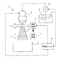
- the figure which shows the testing apparatus which concerns on the 1st form of this invention The flowchart which shows the procedure of the spray measurement method which concerns on a 1st form.
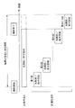
- the figure which shows the example which changes the irradiation position of light The figure which shows the relationship between the injection period of a test liquid, and the irradiation time of light.
- the figure which shows the testing apparatus which concerns on the 2nd form of this invention The flowchart which shows the procedure of the spray measurement method which concerns on a 2nd form.
- the test apparatus 1 includes a tank 4 that stores a test liquid 3 to be injected from a fuel injection valve 2 to be tested, and a pump that pressurizes the test liquid 3 in the tank 4 to a predetermined fuel injection pressure and supplies the fuel to the fuel injection valve 2. 5, an irradiation device 7 for irradiating light L in a specific wavelength region (for example, ultraviolet region) to the spray 6 of the test liquid injected from the fuel injection valve 2, and the spray 6 after being irradiated with the light L And a recovery container 8 to be provided.
- a specific wavelength region for example, ultraviolet region
- the fuel injection valve 2 is a fuel injection valve that injects fuel into the intake air of an in-vehicle internal combustion engine.
- the tank 4 and the pump 5 function as test liquid supply means for supplying the test liquid 3 to the fuel injection valve 2.
- the tank 4 should just be able to store the test liquid 3 of the quantity required for measurement of a spray characteristic.
- the pump 5 may be appropriately selected as long as the test liquid 3 can be pressurized to the fuel injection pressure. Between the pump 5 and the fuel injection valve 2, a pressure accumulating part such as an accumulator for accumulating the pressurized test liquid 3 may be provided.
- the test liquid 3 is prepared by mixing a predetermined curable resin with the fuel to be injected from the fuel injection valve 2.
- a thermosetting resin that is usually liquid and is cured by heating is used.
- a thermosetting resin such as a melamine resin or a urea resin is used as the curable resin.
- the irradiation device 7 irradiates the spray 6 with light L in a specific wavelength region (for example, an ultraviolet region) molded into a predetermined shape as a process for causing the curable resin to cure. Since the fuel contained in the test liquid 3 is colored, when the spray 6 is irradiated with the light L, the energy of the light L is absorbed by the droplets in the spray 6 and changes to heat.
- thermosetting resin is cured, and particles (or fine particles) corresponding to the droplets are generated. That is, the irradiation device 7 functions as a curing unit by irradiating the spray 6 with the light L as a process for causing the thermosetting resin contained in the test solution 3 to have a curing action.
- the thermosetting resin needs to have a curing speed enough to cure in the spray 6 in response to the irradiation of the light L.
- the property of the test liquid 3 containing the thermosetting resin is not significantly different from the property of the fuel to be actually injected from the fuel injection valve 2.
- the irradiation direction of the light L by the irradiation device 7 is with respect to the injection direction of the test liquid 3 from the fuel injection valve 2 (that is, the axial direction of the fuel injection valve 2 and corresponds to the vertical direction in FIG. 1).
- the direction is set to be orthogonal (left and right direction in FIG. 1).
- the irradiation range of the light L with respect to the spray 6 from the irradiation device 7 is set to a partial specific range of the spray 6 with respect to the injection direction of the test liquid 3.
- the irradiation range with respect to the direction orthogonal to the injection direction of the test liquid 3, that is, the width of the light L on the plane orthogonal to the injection direction is set to include the entire spray 6.
- the irradiation range of the light L is set so that the entire spray 6 passes through the irradiation range of the light L and expands to the collection container 8 side. Thereby, the light L can be incident on all the droplets included in the spray 6 and cured.
- the irradiation position of the light L with respect to the ejection direction can be changed along the ejection direction of the test liquid 3.
- the whole or a part of the irradiation device 7 may be provided so as to be movable along the ejection direction, or the irradiation position may be changed by changing a part of the optical path in the irradiation device 7. .
- the center of the irradiation range in the injection direction of the test liquid 3 may be represented as the irradiation position.
- the test apparatus 1 further includes a control unit 9.
- the control unit 9 controls operations of various devices necessary for measuring the spray characteristics such as the fuel injection operation of the fuel injection valve 2, the liquid feeding operation of the pump 5, and the irradiation operation of the irradiation device 7.
- various control devices such as a programmable sequencer and a personal computer that can operate a control target device according to a predetermined procedure can be used.
- a test liquid 3 is prepared by mixing a thermosetting resin at a predetermined ratio with fuel (step S1).
- the test solution 3 is stored in a tank 4.
- the pump 5 is started and the fuel injection valve 2 is driven to inject the test liquid 3 for a predetermined time, and there is spray from the irradiation device 7 in synchronization with the formation of the spray by the injection operation.
- the light L is irradiated at least at a part of the obtaining period (step S2). That is, in step S2, the step of ejecting the test liquid and the step of curing the droplets as particles are performed in parallel.
- the injection operation of the fuel injection valve 2, the on / off of the pump 5, and the irradiation timing of the light L from the irradiation device 7 may be appropriately controlled by the control unit 9.
- the control parameters of the fuel injection valve 2, for example, the pressure of the test liquid 3, the drive duty ratio of the fuel injection valve 2, etc. may be set to the same values as when the fuel is actually injected from the fuel injection valve 2.
- the environmental parameters such as the temperature and pressure of the environment in which the test liquid 3 is injected may be matched with the environment in which the fuel injection valve 2 is actually placed.
- the spray 6 injected from the fuel injection valve 2 is sequentially collected in the collection container 8 including particles hardened by the irradiation of the light L.
- the recovered material in the recovery container 8 is washed and the particles are separated from the recovered material (step S3).
- the test liquid 3 can be used. By washing with the test liquid 3, the hardened particles can be clearly separated from the liquid phase of the recovered material.
- the used cleaning liquid can be collected and used as it is as the test liquid 3 from the next time. However, if the particles can be recovered from the liquid phase without washing, washing may be omitted.
- Step S4 corresponds to a process of analyzing the spray characteristics.
- an analysis can be performed in which the diameter of the obtained particle is measured and the measured value is statistically processed to obtain a particle size distribution and an average diameter.
- the recovered particles are obtained by curing the droplets contained in the spray 6. Therefore, the obtained particle size distribution can be equated with the particle size distribution and average diameter of the droplets contained in the spray 6. Thereby, the spray characteristic of the fuel injection valve 2 can be measured easily and accurately.
- the amount of the gas phase component of the spray 6 can also be obtained by previously grasping the total weight of the test liquid 3 to be injected in one measurement and obtaining the difference from the weight of all the obtained particles. Thereby, it is also possible to know the ratio between the gas phase and the liquid phase of the spray 6.
- the droplets contained in the entire spray 6 can be cured and the particle size distribution of these droplets can be obtained by one measurement. Therefore, the measurement result of the entire spray can be efficiently obtained in a short time as compared with the measurement method in which the partial measurement of the spray is repeated to analyze the entire spray. Further, in the above measurement method, it is sufficient that light is incident on the entire spray 6 in a partial range (specific range) of the spray 6 in the injection direction, and if there is an amount of light sufficient to cure the droplets. The target measurement is possible. Therefore, the spray characteristics can be easily measured even in a region where the spray 6 is dense.
- the method of the comparative example uses the transmitted light necessary for observation because the light is attenuated in a dense spray area Or reflected light cannot be obtained, which makes measurement difficult.
- the measurement method of this embodiment as described above, light only needs to be incident on the entire spray, and if the amount of light necessary for curing can be secured, the attenuation of light will not be a problem. Is possible.
- the droplets being sprayed are cured using the thermosetting resin, there is no possibility that the recovered particles are melted by a subsequent temperature change and returned to the liquid phase.
- the curing reaction of the droplets in the spray 6 can be appropriately controlled. It is also possible to measure part of the spray 6 by irradiating only part of the spray 6 with the light L. Thereby, diversification of the measuring method can be achieved.
- the irradiation position and irradiation timing of the light L with respect to the spray 6 may be set as appropriate.
- the spray characteristics may be analyzed separately when the measurement parameters are changed. For example, as shown in FIG. 3, in one measurement, the irradiation position of the light L with respect to the spray 6 is set near the injection port of the fuel injection valve 2, and in another measurement, the light L is applied to the tip of the spray 6.
- the irradiation position of the light L may be changed for each measurement, and the spray characteristics may be analyzed separately for each irradiation position. In this case, the spray characteristics such as the particle size distribution and the average particle diameter can be analyzed in association with the position of the spray 6.
- irradiation timing for example, as in measurement method A shown in FIG. 4, irradiation of light L (including recovery of particles) is performed throughout the injection period from the start of injection to the end of injection in one measurement. ) May be continued. However, even after the injection is completed, the spray may remain for a certain period thereafter.
- a spray is also included in the measurement target, in the measurement method A, as shown by an imaginary line in FIG. 4, a period in which the spray can exist from the start of injection until a fixed time elapses after the end of injection. And the irradiation of the light L may be continued over the entire period.
- the irradiation time of light L (including the particle recovery time) in one measurement may be limited to a part of the time period during which spraying can exist.
- the irradiation time may be set as a parameter that can be controlled by the control unit 9.
- the control unit 9 functions as an irradiation timing control means.
- the setting of the irradiation time within a period in which the spray can exist may be changed for each measurement, and the spray characteristics may be distinguished and analyzed for each irradiation time.
- the light L is emitted at a certain time from the start of injection in the first measurement, and the light is emitted at a certain time from the end of irradiation in the first measurement in the second measurement. After that, the measurement is repeated while changing the irradiation time.
- the light L is emitted at a fixed time with the injection end time being the end in the Nth measurement (N is an integer of 3 or more).
- the (N + 1) th measurement is performed by irradiating the light L for a certain time immediately after the end of the injection.
- N is an integer of 3 or more
- the entire period in which the spray can exist is divided into a plurality of irradiation times, but a part of the period in which the spray can exist may be divided into a plurality of irradiation times.
- the initial period, the intermediate period, and the final period may be set with appropriate intervals therebetween, and the initial period, the intermediate period, and the final period may be set as the irradiation timing.
- the spray characteristics can be analyzed in association with a specific time during a period in which the spray can exist.
- the temporal change of spray characteristics can also be analyzed by comparing the analysis results for each irradiation period. For example, when the spray characteristics from the start of injection are not steady, it is possible to analyze temporal changes in particle size distribution and the like. However, even if the measurement is performed once, if the spray (including particles) is distinguished and collected according to the timing while continuing the injection of the test liquid 3, the spray according to the timing during the period in which the spray exists. Analysis of characteristics is possible. For example, if the spray 6 is recovered while moving the recovery container 8 in a direction orthogonal to the injection direction, the temporal change in the spray characteristics can be replaced with a position on the recovery container 8 and specified.
- FIG. 5 shows an outline of a test apparatus used in the spray measurement method according to the second embodiment of the present invention.
- the test apparatus 10 in FIG. 5 has a configuration in which a pair of electrodes 11A and 11B, a DC power source 12, and a charging device 13 are added to the basic configuration of the test apparatus 1 in FIG.
- the electrodes 11A and 11B are arranged to face each other in parallel so as to sandwich the fuel injection valve 2 and the region where the test liquid 3 is injected from the fuel injection valve 2 in the irradiation direction of the light L.
- One electrode 11A is connected to the positive electrode of the DC power source 12, and the other electrode 11B is connected to the negative electrode of the DC power source.
- an electric field can be applied between the electrodes 11A and 11B in parallel with the irradiation direction of the light L, as indicated by the broken line arrows in FIG.
- the charging device 13 charges the test solution 3 stored in the tank 4 by applying an electric charge.
- it is configured to perform charging processing by liquid flow.
- the operation of charging the test solution 3 may be performed at a stage before the spray 6 is irradiated with the light L.
- the charging device 13 may be provided so as to charge the test liquid 3 on the way from the tank 4 to the fuel injection valve 2.
- the negative electrode 11B is provided with a holding portion 14 for holding particles adsorbed on the electrode 11B.
- the holding portion 14 may be formed integrally with the electrode 11B, or may be formed as a separate component from the electrode 11B and provided so as to function substantially as a part of the electrode 11B when mounted on the electrode 11B.
- the electrode 11B is provided with a hole or a window through which the light L from the irradiation device 7 passes. However, the irradiation device 7 may be accommodated between the electrodes 11A and 11B.
- step S11 a process for charging the test solution 3 with the charging device 13 is performed.
- the processing is performed so that the test solution 3 is charged to a positive charge.
- step S11 corresponds to a step of charging the test solution.
- a voltage is applied from the DC power source 12 to the electrodes 11A and 11B, and an electric field is applied between them (step S12).
- step S2 injection of the test liquid 3
- step S4 analysis of the collected particles
- the particles are collected to obtain the particle size distribution, as in the first embodiment described above. Spray characteristics such as the average particle diameter can be measured easily and accurately.
- the test liquid 3 is ejected in a positively charged state, the particles hardened by the irradiation with the light L are attracted to the negative electrode 11B and adsorbed by the holding unit 14.
- the adsorption position (arrival position) of the particles with respect to the holding unit 14 is a function of the mass and speed of the particles, and the mass of the particles is determined by the particle size.
- the particle velocity can be specified based on the particle size and the adsorption position of the particle.
- each particle is adsorbed and held in the holding unit 14 with a distribution according to the particle size and the flow velocity.
- the particle P1 has a small particle size and a low velocity
- the particle P2 has a large particle size and a small velocity
- the particle P3 has a small particle size and a high velocity
- the particle P4 has a particle size.
- the particles P1 are adsorbed at the position closest to the fuel injection valve 2
- the particles P4 are adsorbed at the position farthest away.
- the particle P3 is adsorbed at a position farther than the particle P1 because of its high speed
- the particle P2 is adsorbed at a position closer to the particle P4 because of its low speed.
- maintenance part 14 is measured, if the particle size of each particle hold
- the distribution of the particle group can be analyzed by, for example, photographing the entire image of the surface of the holding unit 14. On the other hand, the particle size of each particle on the holding unit 14 can be analyzed by taking an enlarged image of the holding unit 14, for example.
- the holding unit 14 is considered without considering the state of the droplets in the spray 6 before reaching the irradiation range. It is possible to specify the particle velocity by obtaining the particle distribution and the particle size. Also in this embodiment, as in the example of FIG. 3 or FIG. 4 described above, the irradiation position of the light L is changed, or the irradiation timing of the light L is limited to a part of the period during which the spray can exist. The spray characteristics may be measured in more detail by changing the irradiation time.
- the present invention is not limited to the above-described form, and various modifications can be made.
- various energy ray curable resins such as a photocurable resin and an electron beam curable resin may be used instead of the thermosetting resin.
- any resin that has the property of being cured by heat, photochemical reaction, etc. generated by irradiation of energy rays such as visible light, ultraviolet rays, X-rays, electron beams, heat rays, etc. It can be selected as appropriate.
- the energy rays to be irradiated from the irradiation device are not limited to light in a specific wavelength region such as ultraviolet light, and can be appropriately changed according to the selection of the curable resin.
- a resin that causes a curing action by treatment other than irradiation with energy rays may be used as a curable resin to be included in the test liquid.
- the treatment to be applied to the spray can be appropriately selected as long as it causes a curing action to occur in the curable resin.
- the injection valve used for the test in the present invention is not limited to the fuel injection valve of the internal combustion engine, and the liquid to be injected is not limited to the fuel.
- the liquid to be ejected from the test liquid includes a curable resin and a treatment that causes a curing action on the spray can be applied to cure the droplets in the spray as particles, the spray measurement method of the present invention
- the test apparatus can be applied to measurement of sprays from various injection valves.
Landscapes
- Chemical & Material Sciences (AREA)
- Engineering & Computer Science (AREA)
- Life Sciences & Earth Sciences (AREA)
- Health & Medical Sciences (AREA)
- Immunology (AREA)
- Pathology (AREA)
- Physics & Mathematics (AREA)
- Analytical Chemistry (AREA)
- Biochemistry (AREA)
- General Health & Medical Sciences (AREA)
- General Physics & Mathematics (AREA)
- Mechanical Engineering (AREA)
- Combustion & Propulsion (AREA)
- General Engineering & Computer Science (AREA)
- Medicinal Chemistry (AREA)
- Dispersion Chemistry (AREA)
- Food Science & Technology (AREA)
- Fuel-Injection Apparatus (AREA)
- Testing Of Engines (AREA)
- Other Investigation Or Analysis Of Materials By Electrical Means (AREA)
- Investigating Or Analysing Materials By Optical Means (AREA)
- Sampling And Sample Adjustment (AREA)
Abstract
Description
まず、図1を参照して、本発明の第1の形態に係る噴霧計測方法で使用する試験装置の構成を説明する。試験装置1は、試験対象の燃料噴射弁2から噴射させるべき試験液3を収容するタンク4と、タンク4の試験液3を所定の燃料噴射圧に加圧して燃料噴射弁2に供給するポンプ5と、燃料噴射弁2から噴射された試験液の噴霧6に対して特定波長域(例えば紫外域)の光Lを照射する照射装置7と、光Lが照射された後の噴霧6を回収する回収容器8とを備えている。燃料噴射弁2は、一例として、車載用の内燃機関の吸気に対して燃料を噴射する燃料噴射弁である。タンク4及びポンプ5は試験液3を燃料噴射弁2に供給する試験液供給手段として機能する。なお、タンク4は噴霧特性の計測に必要な量の試験液3を蓄えることが可能であればよい。ポンプ5は、試験液3を燃料噴射圧まで加圧できるものであれば適宜に選択されてよい。ポンプ5と燃料噴射弁2との間に、加圧された試験液3を蓄えるアキュムレータ等の蓄圧部が設けられてもよい。
図5は、本発明の第2の形態に係る噴霧計測方法で使用する試験装置の概略を示している。ただし、図5において、図1の試験装置1と共通する要素には同一の参照符号を付し、以下では相違点を中心として説明する。図5の試験装置10では、図1の試験装置1の構成を基本としつつ、これに一対の電極11A、11B、直流電源12及び帯電装置13を追加した構成を有している。電極11A、11Bは、燃料噴射弁2及びその燃料噴射弁2から試験液3が噴射される領域を光Lの照射方向に挟み込むように互いに平行に対向して配置されている。一方の電極11Aは直流電源12の正極に、他方の電極11Bは直流電源の負極にそれぞれ接続される。直流電源12から電極11A、11B間に電圧を印加することにより、図5に破線矢印で示したように、電極11A、11B間に光Lの照射方向と平行に電場を付与することができる。
Claims (18)
- 硬化型樹脂を含んだ試験液を噴射弁から噴射させる工程と、
前記硬化型樹脂に硬化作用を生じさせるための処理を、前記噴射弁から噴射された試験液の噴霧に適用して、該噴霧中の液滴を粒子として硬化させる工程と、
硬化した粒子を利用して前記噴射弁の噴霧特性を分析する工程と、
を備えた噴霧計測方法。 - 前記硬化型樹脂がエネルギー線の照射によって硬化作用を生じる樹脂であり、前記硬化させる工程では、前記処理として、前記エネルギー線を前記噴霧に照射する請求項1に記載の噴霧計測方法。
- 前記硬化型樹脂として熱硬化型樹脂が用いられ、前記エネルギー線として特定波長域の光が用いられる請求項2に記載の噴霧計測方法。
- 前記噴霧に対する前記エネルギー線の照射が、前記噴射弁からの前記試験液の噴射方向に関して前記噴霧の一部の範囲に設定されている請求項2又は3に記載の噴霧計測方法。
- 前記エネルギー線の照射位置を前記噴射方向に沿って変更しつつ、前記照射位置が変更される毎に前記粒子を区別して分析する請求項4に記載の噴霧計測方法。
- 前記エネルギー線の照射時期を、前記試験液の噴霧が存在し得る期間の一部に限定する請求項2~5のいずれか一項に記載の噴霧計測方法。
- 前記試験液の噴霧が存在し得る期間の少なくとも一部を複数の照射時期に区分し、各照射時期に前記エネルギー線を照射し、区分された照射時期毎に前記粒子を区別して分析する請求項2~5のいずれか一項に記載の噴霧計測方法。
- 前記硬化型樹脂を含んだ試験液を、前記処理の適用前の段階で帯電させる工程をさらに備え、
前記硬化させる工程では、前記試験液の噴射方向と直交する方向に電場を発生させる請求項1~7のいずれか一項に記載の噴霧計測方法。 - 前記硬化させる工程では、前記電場によって移動方向が曲げられた粒子を、前記噴射方向に沿って配置された保持部に吸着保持させて回収し、
前記分析する工程では、回収された粒子の前記保持部における分布及び粒径を計測し、得られた粒子の分布及び粒径とに基づいて、粒子の速度分布を特定する請求項8に記載の噴霧計測方法。 - 前記噴射弁が内燃機関の燃料噴射弁であり、前記試験液は前記内燃機関の燃料に前記硬化型樹脂を混合して調製されている請求項1~9のいずれか一項に記載の噴霧計測方法。
- 硬化型樹脂を含んだ試験液を噴射弁に供給する試験液供給手段と、
前記硬化型樹脂に硬化作用を生じさせるための処理を、前記噴射弁から噴射される試験液の噴霧に適用して、該噴霧中の液滴を粒子として硬化させる硬化手段と、
を備えた噴霧試験装置。 - 前記試験液供給手段は、エネルギー線の照射によって硬化作用を生じる硬化型樹脂を含んだ試験液を前記噴射弁に供給し、
前記硬化手段は、前記処理として、前記エネルギー線を前記噴霧に照射する請求項11に記載の噴霧試験装置。 - 前記試験液供給手段は、前記硬化型樹脂として熱硬化型樹脂を前記噴射弁に供給し、
前記硬化手段は、前記エネルギー線として特定波長域の光を照射する請求項12に記載の噴霧試験装置。 - 前記硬化手段は、前記エネルギー線を、前記噴射弁からの前記試験液の噴射方向に関して前記噴霧の一部の範囲に限定して照射するように設けられている請求項12又は13に記載の噴霧試験装置。
- 前記硬化手段は、前記エネルギー線の照射位置を前記噴射方向に沿って変更可能とされている請求項14に記載の噴霧試験装置。
- 前記エネルギー線の照射時期を、前記試験液の噴霧が存在し得る期間の少なくとも一部に限定する照射時期制御手段をさらに備えた請求項11~15のいずれか一項に記載の噴霧試験装置。
- 前記硬化型樹脂を含んだ試験液を帯電させる帯電手段と、
前記試験液の噴射方向と直交する方向に電場を発生させる電場発生手段と、
を備えた請求項11~16のいずれか一項に記載の噴霧試験装置。 - 前記電場発生手段は、前記試験液が噴射される領域を噴射方向と直交する方向に挟み込むように対向して配置された一対の電極を有し、前記試験液の電荷と反対側の極性となる電極には、前記電場によって移動方向が曲げられた粒子を吸着保持する保持部が設けられている請求項17に記載の噴霧試験装置。
Priority Applications (5)
| Application Number | Priority Date | Filing Date | Title |
|---|---|---|---|
| US14/005,646 US9429125B2 (en) | 2011-04-26 | 2011-04-26 | Spray measuring method and spray test apparatus used in the method |
| PCT/JP2011/060138 WO2012147158A1 (ja) | 2011-04-26 | 2011-04-26 | 噴霧計測方法及びその方法に用いる噴霧試験装置 |
| CN201180069006.9A CN103430007B (zh) | 2011-04-26 | 2011-04-26 | 喷雾计测方法以及该方法所使用的喷雾试验装置 |
| JP2013511818A JP5637304B2 (ja) | 2011-04-26 | 2011-04-26 | 噴霧計測方法及びその方法に用いる噴霧試験装置 |
| DE112011105184.0T DE112011105184B4 (de) | 2011-04-26 | 2011-04-26 | Sprühmessverfahren und in dem Verfahren verwendeter Sprühmessapparat |
Applications Claiming Priority (1)
| Application Number | Priority Date | Filing Date | Title |
|---|---|---|---|
| PCT/JP2011/060138 WO2012147158A1 (ja) | 2011-04-26 | 2011-04-26 | 噴霧計測方法及びその方法に用いる噴霧試験装置 |
Publications (1)
| Publication Number | Publication Date |
|---|---|
| WO2012147158A1 true WO2012147158A1 (ja) | 2012-11-01 |
Family
ID=47071700
Family Applications (1)
| Application Number | Title | Priority Date | Filing Date |
|---|---|---|---|
| PCT/JP2011/060138 Ceased WO2012147158A1 (ja) | 2011-04-26 | 2011-04-26 | 噴霧計測方法及びその方法に用いる噴霧試験装置 |
Country Status (5)
| Country | Link |
|---|---|
| US (1) | US9429125B2 (ja) |
| JP (1) | JP5637304B2 (ja) |
| CN (1) | CN103430007B (ja) |
| DE (1) | DE112011105184B4 (ja) |
| WO (1) | WO2012147158A1 (ja) |
Families Citing this family (10)
| Publication number | Priority date | Publication date | Assignee | Title |
|---|---|---|---|---|
| TWI548005B (zh) * | 2014-01-24 | 2016-09-01 | 環旭電子股份有限公司 | 選擇性電子封裝模組的製造方法 |
| CN104181086B (zh) * | 2014-08-27 | 2016-06-22 | 天津商业大学 | 一种喷雾粒径分布二维扫描检测装置及检测方法 |
| US10849384B2 (en) * | 2016-02-03 | 2020-12-01 | Mississippi State University | Facemask and helmet with facemask |
| EP3456953B1 (en) * | 2017-09-13 | 2021-07-14 | Vitesco Technologies GmbH | Apparatus and method for testing a fuel injector nozzle |
| CN110118143B (zh) * | 2018-02-07 | 2020-08-28 | 广州汽车集团股份有限公司 | 一种喷雾落点测试装置及方法 |
| CN109752291A (zh) * | 2019-02-28 | 2019-05-14 | 西北工业大学 | 一种用于监控微小液滴掉落过程的触发装置 |
| CN110985256B (zh) * | 2019-12-19 | 2021-05-14 | 哈尔滨工程大学 | 一种定容弹反射镜端盖及应用该端盖的多孔喷油器喷雾测试系统 |
| CN113565662B (zh) * | 2020-04-28 | 2022-12-20 | 广州汽车集团股份有限公司 | 一种用于测量发动机喷油器喷雾碰壁量的装置及测量方法 |
| CN113530737B (zh) * | 2021-08-17 | 2022-06-03 | 安徽江淮汽车集团股份有限公司 | 发动机喷油器性能综合测试方法 |
| CN116380745B (zh) * | 2023-03-21 | 2026-04-14 | 中国石油大学(北京) | 多孔过滤介质内液体分布特征的检测方法、装置及系统 |
Citations (5)
| Publication number | Priority date | Publication date | Assignee | Title |
|---|---|---|---|---|
| JPS61133974A (ja) * | 1984-12-04 | 1986-06-21 | Mitsubishi Heavy Ind Ltd | 流動微粒子のホログラム作成装置 |
| JPH1090157A (ja) * | 1996-09-19 | 1998-04-10 | Zexel Corp | レーザ回折法を利用した噴霧計測方法とその装置 |
| JP2000162119A (ja) * | 1998-11-25 | 2000-06-16 | Denso Corp | 噴霧測定装置 |
| JP2004340619A (ja) * | 2003-05-13 | 2004-12-02 | Ishikawajima Harima Heavy Ind Co Ltd | 噴霧計測方法及び装置 |
| JP2010090244A (ja) * | 2008-10-07 | 2010-04-22 | Hitachi Chem Co Ltd | 樹脂微粒子の製造方法 |
Family Cites Families (14)
| Publication number | Priority date | Publication date | Assignee | Title |
|---|---|---|---|---|
| US3275744A (en) * | 1962-10-01 | 1966-09-27 | Spraying Systems Co | Apparatus for spray analysis |
| JPS5742839A (en) * | 1980-08-28 | 1982-03-10 | Nitta Zerachin Kk | Method and device for measuring number of ultrafine particles |
| NZ208274A (en) * | 1984-05-24 | 1986-10-08 | M P Best | Calculating aerosol particle size:crystallising droplets on a surface |
| JPH0663961B2 (ja) * | 1986-03-24 | 1994-08-22 | 日本科学工業株式会社 | 液中不純物測定方法とその測定装置 |
| JPH0648238B2 (ja) * | 1986-05-21 | 1994-06-22 | 武征 神本 | 噴射燃料の平均粒径計測装置 |
| JPH03193420A (ja) * | 1989-12-25 | 1991-08-23 | Matsushita Electric Works Ltd | 表面に模様を有する成形品の成形方法 |
| JP3422650B2 (ja) * | 1997-04-18 | 2003-06-30 | 三菱電機株式会社 | 噴霧分布計測装置及び計測方法 |
| DE19844602A1 (de) * | 1998-09-29 | 2000-03-30 | Bosch Gmbh Robert | Verfahren und Vorrichtung zum Messen der Winkelverteilung eines Flüssigkeitsstrahls |
| US6508112B1 (en) * | 2000-01-21 | 2003-01-21 | Dean Verhoeven | Tomographic spray momentum mapping system |
| GB2371858B (en) * | 2001-02-05 | 2004-10-13 | Abb Offshore Systems Ltd | Monitoring particles in a fluid flow |
| US6787029B2 (en) * | 2001-08-31 | 2004-09-07 | Cabot Corporation | Material for chromatography |
| JP2010084249A (ja) * | 2008-09-30 | 2010-04-15 | Brother Ind Ltd | ラメ装飾物、及びその製造方法 |
| AT10542U3 (de) * | 2009-01-19 | 2009-10-15 | Avl List Gmbh | Kondensationskern-zähler |
| WO2012131935A1 (ja) | 2011-03-30 | 2012-10-04 | トヨタ自動車株式会社 | 噴霧検査装置 |
-
2011
- 2011-04-26 CN CN201180069006.9A patent/CN103430007B/zh not_active Expired - Fee Related
- 2011-04-26 US US14/005,646 patent/US9429125B2/en not_active Expired - Fee Related
- 2011-04-26 JP JP2013511818A patent/JP5637304B2/ja not_active Expired - Fee Related
- 2011-04-26 WO PCT/JP2011/060138 patent/WO2012147158A1/ja not_active Ceased
- 2011-04-26 DE DE112011105184.0T patent/DE112011105184B4/de not_active Expired - Fee Related
Patent Citations (5)
| Publication number | Priority date | Publication date | Assignee | Title |
|---|---|---|---|---|
| JPS61133974A (ja) * | 1984-12-04 | 1986-06-21 | Mitsubishi Heavy Ind Ltd | 流動微粒子のホログラム作成装置 |
| JPH1090157A (ja) * | 1996-09-19 | 1998-04-10 | Zexel Corp | レーザ回折法を利用した噴霧計測方法とその装置 |
| JP2000162119A (ja) * | 1998-11-25 | 2000-06-16 | Denso Corp | 噴霧測定装置 |
| JP2004340619A (ja) * | 2003-05-13 | 2004-12-02 | Ishikawajima Harima Heavy Ind Co Ltd | 噴霧計測方法及び装置 |
| JP2010090244A (ja) * | 2008-10-07 | 2010-04-22 | Hitachi Chem Co Ltd | 樹脂微粒子の製造方法 |
Also Published As
| Publication number | Publication date |
|---|---|
| CN103430007A (zh) | 2013-12-04 |
| CN103430007B (zh) | 2015-04-01 |
| US20140033810A1 (en) | 2014-02-06 |
| DE112011105184T5 (de) | 2014-01-30 |
| JP5637304B2 (ja) | 2014-12-10 |
| JPWO2012147158A1 (ja) | 2014-07-28 |
| DE112011105184B4 (de) | 2017-11-02 |
| US9429125B2 (en) | 2016-08-30 |
Similar Documents
| Publication | Publication Date | Title |
|---|---|---|
| JP5637304B2 (ja) | 噴霧計測方法及びその方法に用いる噴霧試験装置 | |
| CN105136752B (zh) | 基于激光诱导击穿光谱的在线粉末检测装置及其测量方法 | |
| JP2018521217A (ja) | 少なくとも一つの三次元物体を付加的に製造する装置 | |
| CN1754967A (zh) | 用于监视激光冲击处理的系统和方法 | |
| KR101583303B1 (ko) | 표면 에너지 측정을 위한 미세액적 분석 장치 및 미세액적 분석 방법 | |
| CN105973852A (zh) | 燃料射流浓度场分布测试装置及其实施方法 | |
| US20140072476A1 (en) | Ionization device, mass spectrometer including the ionization device, and image generation system | |
| DE102015203847B4 (de) | Neutral-Teilchen-Sputter-Massenspektrometer-Vorrichtung | |
| CN116884650B (zh) | 一种对基于闪烁体的快离子损失探针进行实验标定的装置 | |
| Rafie-Zinedine et al. | Enhancing electrospray ionization efficiency for particle transmission through an aerodynamic lens stack | |
| JP2009270982A (ja) | 液滴数密度測定方法および測定装置 | |
| US20160059249A1 (en) | Electrospray with soft x-ray neutralizer | |
| WO2016096521A1 (de) | Vorrichtung zur detektion von partikeln in einem abgas einer verbrennungsmaschine | |
| EP3101410A1 (en) | Observation apparatus, device, device production method, particle diameter measurement method, resistance property observation method, chemical reaction method, particle preservation method, and automated observation apparatus | |
| CN113310860B (zh) | 基于sibs和拉曼光谱的气溶胶颗粒快速检测装置及方法 | |
| Nürnberg | Laser-accelerated proton beams as a new particle source | |
| JP2007127427A (ja) | 微粒子捕集装置及び微粒子捕集方法 | |
| US10283337B2 (en) | Microparticle composition analyzing apparatus | |
| Wang et al. | Physical experiments on the HEAVEN-I KrF laser facility | |
| Spickermann | Laser-driven ion beam characteristics and dose measurements for medical applications | |
| Heston | Linear quadrupole focusing for high resolution microdroplet-based fabrication | |
| Bukharskii et al. | All-optical compact setup for generation of collimated multi-MeV proton beams with a" snail" target | |
| Hünig | Development, characterization, and first field deployments of a novel aerosol mass spectrometer combining laser ablation and flash vaporization techniques for aircraft application at high altitudes | |
| Lommen | Reference Masses for Precision Mass Spectrometry. Design and Implementation of a Pierce Geometry to the Cluster Ion Source at ISOLTRAP | |
| DE10002970A1 (de) | Vorrichtung zur Analyse von in tröpfchenförmigen Flüssigkeitsproben enthaltenen Elementen |
Legal Events
| Date | Code | Title | Description |
|---|---|---|---|
| 121 | Ep: the epo has been informed by wipo that ep was designated in this application |
Ref document number: 11864177 Country of ref document: EP Kind code of ref document: A1 |
|
| ENP | Entry into the national phase |
Ref document number: 2013511818 Country of ref document: JP Kind code of ref document: A |
|
| WWE | Wipo information: entry into national phase |
Ref document number: 14005646 Country of ref document: US |
|
| WWE | Wipo information: entry into national phase |
Ref document number: 1120111051840 Country of ref document: DE Ref document number: 112011105184 Country of ref document: DE |
|
| 122 | Ep: pct application non-entry in european phase |
Ref document number: 11864177 Country of ref document: EP Kind code of ref document: A1 |