WO2012144631A1 - Puce à électrode destinée à détecter une molécule biologique, et procédé de détection d'une molécule biologique - Google Patents
Puce à électrode destinée à détecter une molécule biologique, et procédé de détection d'une molécule biologique Download PDFInfo
- Publication number
- WO2012144631A1 WO2012144631A1 PCT/JP2012/060785 JP2012060785W WO2012144631A1 WO 2012144631 A1 WO2012144631 A1 WO 2012144631A1 JP 2012060785 W JP2012060785 W JP 2012060785W WO 2012144631 A1 WO2012144631 A1 WO 2012144631A1
- Authority
- WO
- WIPO (PCT)
- Prior art keywords
- electrode
- biomolecule
- probe
- electrode substrate
- substrate
- Prior art date
Links
Images


Classifications
-
- G—PHYSICS
- G01—MEASURING; TESTING
- G01N—INVESTIGATING OR ANALYSING MATERIALS BY DETERMINING THEIR CHEMICAL OR PHYSICAL PROPERTIES
- G01N27/00—Investigating or analysing materials by the use of electric, electrochemical, or magnetic means
- G01N27/26—Investigating or analysing materials by the use of electric, electrochemical, or magnetic means by investigating electrochemical variables; by using electrolysis or electrophoresis
- G01N27/28—Electrolytic cell components
- G01N27/30—Electrodes, e.g. test electrodes; Half-cells
- G01N27/327—Biochemical electrodes, e.g. electrical or mechanical details for in vitro measurements
- G01N27/3275—Sensing specific biomolecules, e.g. nucleic acid strands, based on an electrode surface reaction
- G01N27/3276—Sensing specific biomolecules, e.g. nucleic acid strands, based on an electrode surface reaction being a hybridisation with immobilised receptors
-
- G—PHYSICS
- G01—MEASURING; TESTING
- G01N—INVESTIGATING OR ANALYSING MATERIALS BY DETERMINING THEIR CHEMICAL OR PHYSICAL PROPERTIES
- G01N27/00—Investigating or analysing materials by the use of electric, electrochemical, or magnetic means
- G01N27/26—Investigating or analysing materials by the use of electric, electrochemical, or magnetic means by investigating electrochemical variables; by using electrolysis or electrophoresis
- G01N27/403—Cells and electrode assemblies
- G01N27/414—Ion-sensitive or chemical field-effect transistors, i.e. ISFETS or CHEMFETS
- G01N27/4145—Ion-sensitive or chemical field-effect transistors, i.e. ISFETS or CHEMFETS specially adapted for biomolecules, e.g. gate electrode with immobilised receptors
-
- G—PHYSICS
- G01—MEASURING; TESTING
- G01N—INVESTIGATING OR ANALYSING MATERIALS BY DETERMINING THEIR CHEMICAL OR PHYSICAL PROPERTIES
- G01N27/00—Investigating or analysing materials by the use of electric, electrochemical, or magnetic means
- G01N27/26—Investigating or analysing materials by the use of electric, electrochemical, or magnetic means by investigating electrochemical variables; by using electrolysis or electrophoresis
- G01N27/28—Electrolytic cell components
- G01N27/30—Electrodes, e.g. test electrodes; Half-cells
- G01N27/327—Biochemical electrodes, e.g. electrical or mechanical details for in vitro measurements
- G01N27/3275—Sensing specific biomolecules, e.g. nucleic acid strands, based on an electrode surface reaction
- G01N27/3277—Sensing specific biomolecules, e.g. nucleic acid strands, based on an electrode surface reaction being a redox reaction, e.g. detection by cyclic voltammetry
Definitions
- the present invention relates to a biomolecule detection electrode chip and a biomolecule detection method.
- a current detection type DNA chip using a redox label has been reported.
- one end of a molecule called a molecular wire is immobilized on a metal electrode, a DNA probe is bound to the other end of the molecule, and a redox label based on hybridization with a target gene and electrons of the metal electrode are exchanged.
- a method of detecting a target gene by detecting it as a current change is known (see, for example, Nature Biotechnology, vol. 16, (1998) p27, p40).
- a DNA probe is immobilized on the surface of the floating electrode connected to the gate electrode of the field effect transistor, and hybridization is performed on the surface of the floating electrode with the target gene.
- a method for detecting the change of the above using the electric field effect is disclosed (for example, see Japanese Patent Laid-Open No. 2005-077210).
- the method described in Nature Biotechnology, vol. 16, (1998) p27, p40 uses the oxidation-reduction reaction on the metal electrode as the basic principle of detection, so that an oxidizing substance or a reducing substance (for example, ascorbic acid) is contained in the sample. ), An electric current based on oxidation or reduction flows, which may interfere with gene detection and may deteriorate detection accuracy.
- the electrode reaction easily proceeds on the metal electrode along with the current measurement.
- the electrode reaction is irreversible and non-equilibrium reaction, electrode corrosion, gas generation, etc. may occur, and the stability of current measurement may be impaired, especially when repeated measurement is performed, the detection accuracy deteriorates. was there.
- JP-A-2005-072210 although it is a low-cost and highly accurate detection method compared to a biomolecule detection method using an oxidation-reduction reaction, it is difficult to obtain a stable potential, A higher level of accuracy was required.
- An electrode chip for biomolecule detection comprising an electrode having a biomolecule probe immobilization material on which a provided biomolecule probe is immobilized.
- biomolecule detection electrode chip according to any one of ⁇ 1> to ⁇ 4>, wherein the biomolecule probe is a nucleic acid, a polynucleotide, a synthetic oligonucleotide, an antibody, or an antigen.
- ⁇ 6> At least one of a substrate, an electrode substrate, a metal salt and a metal oxide provided on the outermost surface of the electrode substrate opposite to the side on which the substrate is provided, and the outermost surface
- An aqueous solution contact step of contacting a biomolecule detection electrode chip comprising an electrode having a biomolecule probe immobilization material on which the provided biomolecule probe is immobilized with an aqueous solution containing at least one biomolecule; And a detection step of detecting a change in the solid-liquid interface potential of the electrode.
- biomolecule detection method according to any one of ⁇ 6> to ⁇ 9>, wherein the biomolecule probe is a nucleic acid, a polynucleotide, a synthetic oligonucleotide, an antigen, or an antibody.
- the aqueous solution contact step is a step of forming a complementary complex between the biomolecule probe and the nucleic acid that is the biomolecule in the aqueous solution using a single-stranded nucleic acid as the biomolecule probe.
- the method for detecting a biomolecule according to any one of ⁇ 6> to ⁇ 10> above, which is a step of forming an antigen-antibody reaction.
- biomolecule detection electrode chip excellent in potential stability at a solid-liquid interface between a liquid and an electrode, and a biomolecule detection method for accurately detecting a biomolecule.
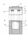
- FIG. 1 is a schematic cross-sectional view showing a configuration example of an electrode chip for biomolecule detection according to the present invention.
- the (A) side in FIG. 2 is a schematic top view showing a configuration example of a laminate of a substrate and an electrode substrate
- the (B) side in FIG. 2 is a side schematic diagram showing a configuration example of a laminate of a substrate and an electrode substrate.
- FIG. The (A) side of FIG. 3 is a schematic top view showing another configuration example of the laminate of the substrate and the electrode substrate
- the (B) side of FIG. 3 is another configuration example of the laminate of the substrate and the electrode substrate.
- It is a side surface schematic diagram which shows. 4A is a schematic side view illustrating a structural example of a transistor
- FIG. 4B is a schematic top view illustrating a structural example of a transistor.
- 5A is a schematic side view illustrating a structural example of a transistor
- FIG. 5B is a schematic top view illustrating a structural example of a transistor.
- FIG. 6 is a schematic diagram showing a configuration example of a measurement system in the biomolecule detection method of the present invention.
- FIG. 7 is a schematic diagram of a single-base extension reaction of a nucleic acid in the biomolecule detection method of the present invention.
- FIG. 8 is a schematic cross-sectional view showing the layer structure of the SAM laminate used in the examples.
- FIG. 9 is an AFM photograph of the surface of the electrode substrate used in the comparative example.
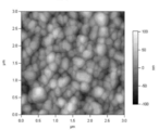
- FIG. 10 is an AFM photograph of the surface of the electrode substrate used in the example.
- FIG. 11 is an AFM photograph of the surface of the electrode substrate used in the example.
- FIG. 12 is an AFM photograph of the surface of the electrode substrate used in the example.
- FIG. 13 is an AFM photograph of the surface of the electrode substrate used in the example.
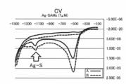
- FIG. 14 is a graph showing a CV curve of the SAM laminate used in the examples.
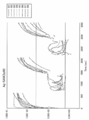
- FIG. 15 is a graph showing XPS spectra of the SAM laminates used in Examples and Comparative Examples.
- FIG. 16 is a graph showing an XPS spectrum of the SAM laminate used in the example.
- FIG. 17 is a table showing the ratio of detected atoms obtained from the XPS spectra of the SAM laminates used in the examples and comparative examples.
- FIG. 18 is a graph showing the change over time of the surface potential on the electrode substrate surface of the SAM laminate used in the comparative example.
- FIG. 19 is a graph showing the time change of the surface potential on the electrode substrate surface of the SAM laminate used in the example.
- FIG. 20 is a graph showing the potential stability of the surface potential on the electrode substrate surface of the SAM laminate used in the examples and comparative examples.
- the (A) side of FIG. 21 is an AFM photograph of the surface of the electrode substrate used in the example, and the (B) side of FIG. 21 is a curve showing the uneven state of the surface of the electrode substrate used in the example.
- FIG. 22 is a graph showing the potential stability of the surface potential of the electrode substrate used in the example.
- FIG. 23 is a graph showing the potential stability of the surface potential of the electrode substrate used in the example.
- FIG. 24 is a schematic cross-sectional view showing another configuration example of the biomolecule detection electrode chip of the present invention.
- FIG. 25 is a graph showing the surface potential difference of the electrode substrate used in the reference example.
- FIG. 26 is a graph showing the surface potential difference of the electrode substrate used in the reference example.
- FIG. 27 is a graph showing the surface potential difference of the electrode substrate used in the reference example.
- FIG. 28 is an epifluorescence microscope image of the electrode substrate used in the reference example.
- FIG. 29 is an epifluorescence microscope image of the electrode substrate used in the reference example.
- FIG. 30 is an epifluorescence microscope image of the electrode substrate used in the reference example.
- FIG. 31 is a graph showing the change over time of the surface potential of the electrode substrate used in the example.
- FIG. 32 is a bar graph showing the surface potential of the electrode substrate used in the example.
- the electrode chip for biomolecule detection of the present invention includes at least a substrate, an electrode substrate, and a metal salt and a metal oxide provided on the outermost surface of the electrode substrate opposite to the side on which the substrate is provided.
- an electrode having a biomolecular probe immobilization material on which the biomolecular probe provided on the outermost surface is immobilized is configured.
- biomolecules it is known to detect the concentration of biomolecules in a solution as an electrical signal and to quantitatively detect the presence of biomolecules. For example, when an electrode on which a biomolecule probe for capturing a target biomolecule is immobilized is immersed in a solution containing the biomolecule, the biomolecule probe captures the biomolecule and It is known to capture signals.
- a method for capturing an electric signal a current method for capturing the presence of a biomolecule by a change in current and a potential method for capturing by presence of a change in potential are known.
- a current method for example, it is known to use an oxidation-reduction reaction on a metal electrode.
- an oxidizing substance or a reducing substance for example, ascorbic acid
- an electric current based on oxidation or reduction flows, and the detection of biomolecules is hindered, and the detection accuracy may deteriorate. It was.
- an electrode reaction advances on a metal electrode with current measurement. Since the electrode reaction is irreversible and non-equilibrium reaction, corrosion of the metal electrode, generation of gas, and the like occur, and the stability of current measurement is impaired. In particular, the detection accuracy may be deteriorated when repeatedly measuring.
- the above-described biomolecule probe can detect a change in potential at the solid-liquid interface between the electrode and the solution (change in surface charge density) caused by capturing a charged biomolecule.
- a change in potential is detected by a transistor using a field effect.
- metal is generally used as an electrode material, and gold has been conventionally used because it does not cause corrosion due to a solution.
- the potential drift should be suppressed in order to detect the change in potential based on the presence of the biomolecule with high accuracy. That is, by using an electrode material that does not easily polarize and placing the electrode in an environment where the ion concentration in the solution is difficult to increase or decrease, the potential at the solid-liquid interface between the electrode and the solution becomes stable, and potential drift is less likely to occur. Conceivable.
- the electrode chip for biomolecule detection includes a substrate, an electrode substrate, and a metal salt and a metal provided on the outermost surface of the electrode substrate opposite to the side on which the substrate is provided. It is configured to include at least one of oxides and an electrode having a biomolecular probe immobilization material on which a biomolecular probe provided on the outermost surface is immobilized. That is, the electrode material contains at least one of a metal salt and a metal oxide.
- the metal salt is represented as MX
- the metal salt is dissociated into a metal ion (M + ) and a salt ion (X ⁇ ) in an aqueous solution, and is in an equilibrium state as represented by the following formula (1).
- the metal oxide is also dissociated in an aqueous solution to reach an equilibrium state. That is, when the metal oxide is expressed as MO, the metal oxide MO ⁇ is in equilibrium with the hydroxide (MOH) in the aqueous solution, and further becomes MOH 2 + depending on the liquidity (pH) of the aqueous solution. . MO ⁇ , MOH, and MOH 2 + are considered to be in an equilibrium state as shown in the following equation (2).
- the biomolecule detection electrode chip according to the present invention is immersed in an aqueous solution containing X ⁇ ions when it contains a metal salt, and an aqueous solution containing H + ions when it contains a metal oxide, Is in an equilibrium state, and the potential at the solid-liquid interface between the electrode and the solution is considered to be stable. That is, it is considered that potential drift hardly occurs.
- metal salts, metal salts and metal oxides that serve as electrode materials do not cause polarization, and from this point of view, it is considered that potential drift is unlikely to occur. From the above, it is considered that the biomolecule detection electrode chip of the present invention is excellent in potential stability at the solid-liquid interface between the liquid and the electrode.
- the biomolecule detection electrode chip of the present invention having excellent potential stability at the solid-liquid interface between the liquid and the electrode is brought into contact with an aqueous solution containing at least one biomolecule (for example, the chip is immersed in the aqueous solution). If the change in the solid-liquid interface potential of the electrode is detected, the change in potential based on the presence of the biomolecule can be detected more accurately, and the biomolecule can be detected with high accuracy.
- biomolecule detection electrode chip and the biomolecule detection method of the present invention will be described in detail.
- the electrode chip for biomolecule detection of the present invention includes at least a substrate, an electrode substrate, and a metal salt and a metal oxide provided on the outermost surface of the electrode substrate opposite to the side on which the substrate is provided.
- an electrode having a biomolecular probe immobilization material on which the biomolecular probe provided on the outermost surface is immobilized is configured.
- the biomolecule detection electrode chip may further include one or more intermediate layers between the substrate and the electrode.
- the biomolecule detection electrode chip has at least one of a metal salt and a metal oxide on the outermost surface of the electrode
- the metal At least one of the salt and the metal oxide will come into contact with the aqueous solution.
- the metal salt or metal oxide is dissociated, the ions in the aqueous solution are in an equilibrium state, and the potential at the solid-liquid interface between the electrode and the aqueous solution can be stabilized.
- the biomolecule detection electrode chip has a biomolecule probe immobilization material on which the biomolecule probe is immobilized on the outermost surface of the electrode, so that the biomolecule detection electrode chip can be placed in an aqueous solution containing a biomolecule.
- the biomolecular probe comes into contact with the aqueous solution when immersed in the solution.
- the biomolecule probe captures the biomolecule in the aqueous solution, and the change in the potential changed by the charge of the biomolecule can be detected.
- FIG. 1 shows a biomolecule comprising a substrate 10, an intermediate layer 20 located on the substrate 10 and adjacent to the substrate 10, and an electrode 30 located on the intermediate layer 20 and adjacent to the intermediate layer 20.
- a detection electrode tip 100 is shown.
- the electrode 30 has a metal electrode substrate 32, an inorganic layer 34 composed of at least one of a metal salt and a metal oxide having the electrode substrate 32 as a metal element on the outermost surface of the electrode 30, and a biomolecular probe A biomolecular probe immobilization layer 36 formed using an immobilization material is formed.
- the electrode substrate 32 is covered with the inorganic layer 34 and the biomolecular probe immobilization layer 36 and is not exposed.
- a biomolecule probe 38 is immobilized on the biomolecule probe immobilization layer 36.
- the amount of change in potential detected when the biomolecule detection electrode chip 100 is immersed in an aqueous solution containing biomolecules is measured by a potential measuring device (not shown) connected to the electrode substrate 32 via a lead wire or the like. can do.
- a potential measuring device not shown
- the electrode has at least one of a metal salt and a metal oxide provided on the outermost surface of the electrode substrate opposite to the side on which the substrate is provided. That is, the electrode may include an electrode substrate having only a metal salt on the outermost surface, or may include an electrode substrate having only a metal oxide, or an electrode having both a metal salt and a metal oxide. A substrate may be included.
- the metal salt is not particularly limited.
- silver chloride, calcium chloride, barium chloride, magnesium chloride, zinc chloride, aluminum chloride, calcium nitrate, aluminum sulfate, silver sulfide, silver bromide, silver iodide, platinum chloride, etc. Is mentioned.
- Only one type of metal salt may be used, or two or more types may be used.
- the metal salt is preferably a metal chloride.
- the metal constituting the metal salt is preferably one having good affinity with the biomolecular probe immobilization material described later.
- the metal constituting the metal salt is preferably a metal having a good affinity for a sulfur atom.
- a metal having a good affinity for a sulfur atom Specifically, silver, platinum, Or it is preferable that it is zinc and it is more preferable that it is silver.
- the metal oxide is not particularly limited.
- the metal constituting the metal salt has good affinity with the biomolecular probe immobilization material described later.
- the metal constituting the metal salt is preferably a metal having a good affinity for sulfur atoms.
- tantalum (Ta) Platinum, gold, or titanium is preferable, and tantalum is more preferable.
- the electrode substrate having a metal salt or metal oxide may be an inorganic material such as glass, metal, ITO (Indium Tin Oxide), or an organic material such as polyester or polyolefin.
- the electrode substrate is preferably a metal, and the electrode substrate is composed of a metal or metal oxide constituting the metal salt. More preferably, it is a constituent metal.
- the electrode substrate surface includes at least one of a metal salt and a metal oxide from the viewpoint of the stability of the potential of the solid-liquid interface between the aqueous solution containing biomolecules and the electrode. It is preferable that the inorganic layer is coated with a biomolecular probe immobilization layer formed using a biomolecular probe immobilization material and is not exposed.
- the metal salt or metal oxide only needs to be present on the electrode substrate.
- it may be present as an inorganic layer composed of a metal salt or metal oxide formed on the surface of the electrode substrate.
- a method of forming an inorganic layer composed of a metal salt or metal oxide on the surface of the electrode substrate a method of adhering a separately prepared metal salt or metal oxide on the electrode substrate, a surface of the electrode substrate that is metal And the like, and the like.
- an adhesive such as an epoxy compound is applied to the electrode substrate or metal salt or metal oxide, so that the electrode substrate and the metal salt or metal oxide are oxidized.
- a method of depositing a metal salt or metal oxide on an electrode substrate using an electron beam or the like, or a method of forming by sputtering For example, in order to form a metal oxide layer composed of tantalum oxide on ITO using ITO as an electrode substrate, tantalum oxide may be deposited on the ITO surface. The layer thickness of the tantalum oxide layer can be controlled by adjusting the deposition time.
- Surface treatment of the electrode substrate that is a metal by chemical reaction includes a solution such as a chelating agent solution containing hydrochloric acid, nitric acid, or salt ions, or a gas such as oxygen gas or ozone gas on the surface of the metal electrode substrate.
- a solution such as a chelating agent solution containing hydrochloric acid, nitric acid, or salt ions, or a gas such as oxygen gas or ozone gas on the surface of the metal electrode substrate.
- the method of giving is mentioned.
- the surface of the electrode substrate that is a metal may be surface-treated with a solution that can be used as a target metal salt.
- a chelating agent for example, PDTA; 1,3-Propanediamine Tetraacetic Acid
- Fe 3+ as a ligand
- a chelating agent for example, PDTA; 1,3-Propanediamine Tetraacetic Acid
- the surface of the metal electrode substrate may be oxidized.
- the surface of the metal electrode substrate may be oxidized.
- the electrode substrate may be oxidized by applying a solution containing an oxidizing agent such as hydrogen or spraying oxygen gas, ozone gas, or the like.
- the method for forming the inorganic layer composed of the metal salt on the electrode substrate is preferably a method in which the surface of the electrode substrate that is a metal is surface-treated by a chemical reaction. Moreover, the method of forming the inorganic layer comprised by the metal oxide on the electrode substrate can also vapor-deposit a metal oxide on the surface of the electrode substrate which is a metal.
- the thickness of the inorganic layer including a metal salt or metal oxide is preferably 1 nm to 100 nm, and more preferably 1 nm to 10 nm.
- an inorganic layer composed of a metal salt or a metal oxide on the electrode substrate means that, for example, the surface of the electrode substrate is subjected to AFM (Atomic Force Microscope), TEM (Transmission Electron Microscope). It can be confirmed by photo observation using a microscope such as Transmission (Electron Microscope).
- AFM Atomic Force Microscope
- TEM Transmission Electron Microscope
- Biomolecular probes biomolecular probe immobilization materials
- the electrode has a biomolecular probe immobilization material on which a biomolecular probe provided on the outermost surface of the electrode substrate is immobilized.
- Biomolecular probes include nucleic acids, polynucleotides, synthetic oligonucleotides, antibodies, or antigens. These may be fragments or the like.
- oligonucleotides, cDNA fragments and the like are usually composed of 300 or less bases. When an oligonucleotide is used, it is preferably a nucleic acid fragment having a base length of 80 or less.
- biomolecule probe is bound (immobilized) to the biomolecule probe immobilization material, and specifically binds or reacts with the biomolecule in the aqueous solution containing the biomolecule.
- the biomolecular probe is a single-stranded probe (for example, single-stranded DNA), and after complementary strand binding with the target DNA, a single-base extension reaction that reacts complementarily with the base of the target DNA is used. Specific biomolecules can also be detected with high accuracy. Details of the biomolecule detection method will be described later.
- the biomolecular probe immobilization material is a material for immobilizing the biomolecular probe on the electrode. In order for the electrode to accurately detect the charge of the biomolecule, it is important that the biomolecule probe that captures the biomolecule and the electrode substrate are bound (immobilized).
- biomolecular probe immobilization material examples include a sulfur-containing compound, a silyl group-containing compound, streptavidin (hereinafter also simply referred to as “avidin”), and the like.
- examples of the sulfur-containing compound include alkane thiols and alkane disulfides having an alkyl chain.
- examples of the silyl group-containing compound include alkyl alkoxysilanes having an alkyl chain. Both the sulfur-containing compound and the silyl group-containing compound may be a sulfur-containing compound or a silyl group-containing compound having a polymer chain represented by polyethylene glycol (PEG) instead of the alkyl chain.
- PEG polyethylene glycol
- Sulfur has a high affinity with noble metals such as gold, silver and platinum.
- the salt ion of the metal salt (Cl ⁇ in the case of AgCl) is exposed on the outermost surface of the electrode, and when the metal oxide is present on the outermost surface of the electrode, The metal oxide oxygen ions (O ⁇ ) are exposed on the outermost surface of the electrode.
- salt ions for example, Cl ⁇
- oxygen ions are replaced with sulfur, and the metal and sulfur are bonded.
- the silyl (Si) group has a high affinity with oxygen ions.
- oxygen ions (O ⁇ ) of the metal oxide are exposed on the outermost surface of the electrode.
- a silyl group-containing compound is allowed to act on the oxide of the electrode, oxygen ions (O ⁇ ) and sulfur atoms are bonded.
- a thiol group-containing compound when a thiol group-containing compound is first allowed to act on the metal electrode surface, sulfur is bonded to the metal surface and the thiol group-containing compound is immobilized. Thereafter, when the electrode surface is brought into contact with a reaction solution such as PDTA, a metal salt such as silver chloride is formed on the metal electrode surface where the thiol group-containing compound is not formed.
- a reaction solution such as PDTA
- a metal salt such as silver chloride
- the thickness of the metal salt (silver chloride) layer can be controlled, and the size of the thiol-containing compound, for example, the length of the alkyl group can be controlled.
- the relative position between the functional group (amino group, carboxyl group, aldehyde group, etc.) of the thiol group-containing compound and the metal salt surface, the distance, and the flexibility of the thiol group-containing compound are controlled and optimized. be able to.
- Avidin may be immobilized on the electrode by modifying a part of the molecule with a sulfur-containing compound such as alkanethiol or a silyl group-containing compound such as alkylalkoxysilane.
- a sulfur-containing compound such as alkanethiol or a silyl group-containing compound such as alkylalkoxysilane.
- the binding (immobilization) of the biomolecule probe immobilization material and the biomolecule probe is performed by, for example, modifying either one end of the biomolecule probe or one end of the biomolecule probe immobilization material with an amino group, Is modified with a carboxy group, and the two may be bound by an amide bond or the like.
- the amino group or carboxy group need not be modified.
- the one end may be modified with an aldehyde group and bonded to an amino group.
- biomolecular probe immobilization material is avidin
- biotin having high affinity with avidin Avidin is composed of four subunits, each having a biotin binding site, and thus can bind to four biotins per molecule. Therefore, by modifying biotin at one end of the biomolecule probe, the biomolecule probe immobilization material and the biomolecule probe can be bound (immobilized) using the avidin-biotin bond.
- the biomolecular probe immobilization material is preferably a sulfur-containing compound.
- the sulfur-containing compound functions as a self-assembled membrane (SAM).
- SAM self-assembled film
- SAM refers to a thin film having a structure with a certain order formed by a mechanism of the film material itself without fine control from the outside. This self-organization forms ordered structures and patterns over long distances in a non-equilibrium situation.
- Sulfur-containing compounds such as alkanethiols and alkane disulfides are adsorbed spontaneously on substrates containing noble metals such as noble metals such as gold and silver, metal salts composed of noble metals, and oxides composed of noble metals.
- a monomolecular-sized thin film is given. Therefore, the biomolecule probe can be immobilized on the electrode at a high density, and the detection accuracy of the biomolecule can be further increased.
- a target gene which is a biomolecule to be detected is detected by hybridization with a biomolecule probe (for example, a DNA probe).
- a biomolecule probe for example, a DNA probe.
- the aforementioned biomolecular probe immobilizing material having a hydrophobic group such as alkanethiol is likely to gather due to the interaction of the hydrophobic chain of the alkyl group, resulting in a domain shape.
- Biomolecules such as proteins tend to be adsorbed on a hydrophobic surface, so that they tend to gather and become overcrowded.
- a component having a hydrophilic group such as sulfobetaine (SB) may be mixed with a biomolecular probe immobilization material having a hydrophobic group.
- SBA sulfobetaine
- sulfobetaine is a highly hydrophilic molecule having both a positive charge and a negative charge, it can be mixed with a hydrophobic molecule such as alkanethiol to form a SAM. And hydrophilicity can be adjusted. As a result, it is possible to suppress biomolecular structural damage.
- Specific examples of SB include Sulfobetaine 3-undecanethiol.
- the hydrophobicity and hydrophilicity of the SAM surface can be adjusted by changing the mixing ratio between the hydrophilic component and the biomolecular probe-immobilized material having a hydrophobic group.
- the molar ratio of the DNA probe to sulfobetaine (SB) [DNA probe: SB] is preferably in the range of 1: 1 to 1:10. In order to obtain high hybridization efficiency, 1: 1 is more preferable.
- the DNA probe density on the electrode surface is 0.04 probes / (nm) 2 , that is, 0.04 DNA probes per square nanometer. At this time, the distance between adjacent DNA probes is about 5 nm. Considering that the diameter of the double-stranded DNA is 2 nm, it can be said that the distance between the probes is moderate.
- the DNA probe density is preferably 0.1 probe / (nm) 2 or less.
- a biomolecule probe immobilization material solution in which the biomolecule probe immobilization material is dissolved is applied to the electrode substrate. It may be applied directly or on a layer composed of a metal salt or metal oxide and dried.
- the biomolecule probe may be bonded to the biomolecule probe immobilization material after forming the biomolecule probe immobilization layer.
- the biomolecule probe immobilization material to which the biomolecule probe is bonded is dissolved in a solvent, and the solution is used as an electrode substrate or a metal salt or metal oxide. You may give on the layer comprised by a thing.
- a solution is applied by spin coating, air knife coating, bar coating, blade coating, slide coating, curtain coating, or the like. And a method of applying by a dropping method, a spray method, a vapor deposition method, a casting method, a dipping method, or the like.
- the biomolecule probe immobilization material or the solution in which the biomolecule probe immobilization material bound to the biomolecule probe is dissolved randomly on the electrode substrate or the layer composed of a metal salt or metal oxide. It may be given, arranged in an array, or given in a lump in a domain. Moreover, you may provide in pattern form.
- a solvent for dissolving the biomolecule probe immobilization material or the biomolecule probe immobilization material to which the biomolecule probe is bound water, alcohol, or a mixed solvent thereof is used.
- a water-insoluble organic solvent may be used, but when the biomolecule probe immobilization material to which the biomolecule probe is bound is dissolved, from the viewpoint of handling the biomolecule.
- Water, a water-soluble solvent such as alcohol, or a mixed solvent thereof is used. Among these, water, ethanol, or a mixed solvent thereof is preferable.
- the biomolecular probe can be immobilized on the electrode.
- the biomolecule probe can be immobilized in various shapes such as a pattern and an array by using a solution in which the biomolecule probe immobilization material or the biomolecule probe immobilization material bound to the biomolecule probe is dissolved.
- FIG. 1 shows a state in which the inorganic layer 34 and the biomolecule-immobilized layer 36 are formed in a domain shape. This is because, for example, when the molecules constituting the biomolecule-immobilized layer 36 are hydrophobic, such as an alkyl chain of alkanethiol, they aggregate in a domain by self-organization using a hydrophobic interaction between molecules as a driving force. Therefore, a form as shown in FIG. 1 is formed.
- a pattern structure as shown in FIG. 1 can be artificially formed by a lithography technique.
- the molecules forming the biomolecule-immobilized layer 36 are hydrophilic, such as polyethylene glycol, aggregation between the molecules does not occur. Therefore, the inorganic layer 34 and the biomolecule-immobilized layer 36 can be mixed randomly. it can. This is effective in controlling the distance between the biomolecules and the reaction efficiency when the biomolecule 38 is immobilized on the surface of the biomolecule-immobilized layer 36.
- the size of the biomolecule and the reaction mode are shown in FIG. It is desirable to select such a domain arrangement or a random arrangement.
- the electrode substrate is previously formed in a desired shape, and the biomolecule probe immobilization material or biomolecule probe is bound on the electrode substrate having such a shape.
- An embodiment in which a solution in which the probe immobilization material is dissolved may be applied.
- FIG. 2 shows a laminate 200 in which a patterned electrode substrate 130 is provided on a glass substrate 110.
- the (A) side of FIG. 2 is a schematic top view of the stacked body 200
- the (B) side of FIG. 2 is a schematic side view of the stacked body 200.
- 2A includes an electrode substrate 130 in which a rectangular electrode substrate 130a and a circular electrode substrate 130c are connected to each other on a glass substrate 110 by a linear electrode substrate 130b. It is shown.
- the same reference numerals are used on the (A) side in FIG.
- a layer composed of a metal salt or a metal oxide and a biomolecule probe immobilization layer on which a biomolecule probe is immobilized are formed on a circular electrode substrate 130c, and the linear electrode substrate 130b is used as a wiring.
- a potential of a biomolecule can be detected by connecting a potential measuring device to the rectangular electrode substrate 130a.
- a resist for example, Nippon Kayaku Co., Ltd., SU-8 may be applied.
- FIG. 3 shows a laminate 202 in which a resist is provided on the laminate 200 shown in FIG.
- the (A) side in FIG. 3 is a schematic top view of the laminate 202
- the (B) side in FIG. 3 is an alternate long and short dash line connecting the X and Y shown in FIG. It is a side surface schematic diagram of the laminated body 202 in-).
- a layer made of a metal salt or metal oxide can be formed by applying a solution for surface treatment such as hydrochloric acid to the exposed circular electrode substrate 130c.
- a biomolecule probe immobilization layer on which the biomolecule probe is immobilized is formed by applying a solution in which the biomolecule probe immobilization material bonded with the biomolecule probe is applied to the exposed circular electrode substrate 130c. be able to.
- the fact that the biomolecular probe immobilization material is immobilized on the electrode substrate means that, for example, X-ray photoelectron spectroscopy such as XPS (X-ray Photoelectron Spectroscopy) or ESCA (Electron Spectroscopy for Chemical Analysis) is performed on the electrode substrate surface. This can be confirmed by performing an analysis. For example, when alkanethiol is used as the biomolecular probe immobilization material, a peak derived from a sulfur atom is detected when the alkanethiol is immobilized on the electrode substrate. In addition, it can be confirmed that the biomolecule probe is immobilized on the biomolecule probe immobilization material, for example, by labeling the biomolecule with a fluorescent molecule and performing fluorescence detection.
- the biomolecule detection electrode chip includes a substrate for supporting the electrode substrate.
- the substrate is not particularly limited, and may be an inorganic material typified by a glass substrate, an ITO substrate, a metal substrate, or the like, or an organic material typified by a polyester substrate, a polyolefin substrate, or the like.
- a semiconductor provided with an electronic device such as a field effect transistor (FET) may be used as the substrate.
- FET field effect transistor
- one or more intermediate layers may be provided between the substrate and the electrode substrate.
- the intermediate layer can be a functional layer such as an adhesive layer for improving the adhesion between the substrate and the electrode substrate.
- an adhesive layer it is preferable to use a material having good affinity with both the substrate and the electrode substrate.
- Ti titanium
- FIG. 4 shows a schematic diagram of a floating gate type FET
- FIG. 5 shows a schematic diagram of an extended type FET. 4 and 5, the (A) side is a cross-sectional view, and the (B) side is a top view.
- a floating gate type FET (hereinafter referred to as “F-FET”) is shown.
- the F-FET is formed on the silicon substrate 12, the drain 14D and the source 14S which are provided on the silicon substrate 12, and on the silicon substrate 12, the drain 14D and the source 14S.
- a floating electrode 18 is formed on a channel region between the drain 14D and the source 14S, and the potential is detected by the floating electrode 18. Therefore, in the F-FET, the channel region between the drain 14D and the source 14S is located in the region vertically below the floating electrode 18, as shown on the (B) side in FIG.
- an extended FET (hereinafter referred to as “E-FET”) is shown on the (A) side of FIG.
- the E-FET is formed on the silicon substrate 12, the drain 14D and the source 14S which are provided on the silicon substrate 12, and on the silicon substrate 12, the drain 14D and the source 14S.
- an extraction electrode 15 is provided inside the insulating film 16.
- the channel region between the drain 14D and the source 14S is not located in the region below the floating electrode 18, and the region below the floating electrode 18 is vertically below.
- One end of the extraction electrode 15 is located in the region.
- a channel region between the drain 14D and the source 14S is located in a region vertically below the other end of the extraction electrode 15.
- the gate insulating film 16 includes silicon oxide (SiO 2 ), silicon nitride (SiN), aluminum oxide (Al 2 O 3 ), A material such as tantalum oxide (Ta 2 O 5 ) is used singly or in combination, and in order to keep the transistor operation normally, silicon nitride (SiN), aluminum oxide (Al 2 O 3 ) on silicon oxide (SiO 2 ). ) Or tantalum oxide (Ta 2 O 5 ).
- the gate electrode 17 is preferably polysilicon (Poly-Si), and has good consistency with a so-called self-alignment process in which the source 14S and the drain 14D are formed by ion implantation through the polysilicon gate.
- the floating electrode 18 is preferably made of a material having a high affinity with the electrode substrate, and a noble metal such as gold, platinum, silver, or palladium can be used.
- the extraction electrode 15 is used as a wiring, a material with low resistance and good workability such as etching is preferable.
- a material with low resistance and good workability such as etching is preferable.
- the material polysilicon (Poly-Si), aluminum, molybdenum, or the like can be used.
- the extraction electrode 15 and the floating electrode 18 can be formed of the same material such as gold.
- the biomolecule detection method of the present invention includes a substrate, an electrode substrate, and at least one of a metal salt and a metal oxide provided on the outermost surface of the electrode substrate opposite to the side on which the substrate is provided,
- a biomolecule detection electrode chip provided with an electrode having a biomolecule probe immobilization material on which the biomolecule probe provided on the outermost surface is immobilized is brought into contact with an aqueous solution containing at least one kind of biomolecule. It has an aqueous solution contact step and a detection step for detecting a change in the solid-liquid interface potential of the electrode.
- the biomolecule detection method of the present invention comprises an aqueous solution contact step in which the biomolecule detection electrode chip of the present invention described above is contacted with an aqueous solution containing at least one biomolecule, and a solid-liquid interface potential of the electrode. And a detecting step for detecting a change in the above.
- the biomolecule detection electrode chip of the present invention is brought into contact with an aqueous solution containing at least one kind of biomolecule (hereinafter also referred to as “biomolecule aqueous solution”).
- biomolecule aqueous solution a method in which at least one of a metal salt and a metal oxide provided in an electrode chip for biomolecule detection, and a biomolecule probe immobilized on a biomolecule probe immobilization material are in contact with an aqueous solution. If it is, it will not be restrict
- the outermost surface of the electrode of the biomolecule detection electrode chip is immersed in the biomolecule aqueous solution, or the biomolecule aqueous solution is dropped on the outermost surface of the electrode of the biomolecule detection electrode chip, or the biomolecule detection is performed in the biomolecule aqueous solution.
- the electrode tip for use may be immersed.
- the potential of the solid-liquid interface between the electrode and the aqueous solution is stabilized by at least one of the metal salt and the metal oxide included in the biomolecule detection electrode chip of the present invention.
- the biomolecule probe immobilized on the biomolecule probe immobilization material included in the biomolecule detection electrode chip of the present invention captures the biomolecule in the aqueous solution and the solid-liquid interface generated by the capture of the biomolecule. By detecting the change in potential, the presence of a biomolecule can be quantitatively detected.
- the biomolecule probe is a DNA probe having a base sequence complementary to the target gene
- an appropriate reaction condition is applied.
- the target gene and the DNA probe form a complementary complex [Hybridization].
- the biomolecule probe captures the biomolecule.
- Detection process a change in the solid-liquid interface potential between the electrode provided in the biomolecule detection electrode chip and the biomolecule aqueous solution or the detection solution is detected.
- Biomolecules in the aqueous biomolecule solution are positively charged or negatively charged.
- the aqueous biomolecule solution is generally prepared in a buffer solution (buffer solution) having a pH of 7-8. Under such a pH environment, DNA is negatively charged.
- the charged nucleic acid forms a complex by hybridization with the DNA probe, which is a biomolecule probe, so that the charge density changes at the solid-liquid interface between the electrode and the biomolecule aqueous solution, and the surface potential changes. To do.
- a cleaning step of cleaning the biomolecule detection electrode tip with a cleaning liquid may be incorporated before the inspection step.
- the washing liquid is not particularly limited as long as it is a liquid that can remove the aqueous biological component solution attached to the biomolecule detection electrode chip, and examples thereof include water, a phosphate buffer solution, an aqueous NaCl solution, and physiological saline.
- the biomolecule detection electrode chip of the present invention After bringing the biomolecule detection electrode chip of the present invention into contact with the biomolecule aqueous solution, the biomolecule detection electrode chip is washed with a cleaning liquid, and other biomolecules or interference other than the target adsorbed nonspecifically on the electrode chip By removing the components, highly accurate measurement can be performed.
- a solution for detecting a potential change at the solid / liquid interface of the electrode is introduced onto the surface of the electrode chip.
- An electric double layer is formed at the solid / liquid interface, and the potential change at the solid / liquid interface depends on the electric double layer.
- the width (thickness) of the electric double layer is called a Debye length, which is a function of ionic strength.
- the Debye length is small in a solution with a high salt concentration, for example, about 1 nm in a NaCl solution of 100 mmol / L (hereinafter also referred to as mM).
- the Debye length increases in the diluted solution, for example, about 10 nm in a 1 mmol / L NaCl solution.
- the Debye length is long.After washing and removing the aqueous solution of the biological component adhering to the biomolecule detection electrode chip, it is replaced with a detection solution with an optimized concentration and fixed. It is desirable to measure the potential change at the / liquid interface.
- a phosphate buffer solution having a concentration of 1 mmol / L to 10 mmol / L is applied to an electrode tip on a metal oxide surface, and 1 mmol / L to 10 mmol / L is applied to an electrode tip on a metal salt surface such as silver chloride.
- a sodium chloride aqueous solution or a potassium chloride aqueous solution having a concentration can be used.
- Such a change in potential is measured by a potential measuring device connected to the electrode.
- the potential measuring device include an electrometer manufactured by Keithley.
- the change in the surface potential of the electrode may be measured by the FET described above.
- the change in the surface potential has the same effect as the change in the gate voltage of the FET, and changes the conductivity of the channel.
- the drain current flowing between the source and the drain the formation of a complex by hybridization, that is, the presence of the target gene can be detected.
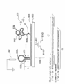
- FIG. 6 is a schematic diagram showing a configuration example of a measurement system in the biomolecule detection method of the present invention.
- the measurement system shown in FIG. 6 uses a biomolecule detection electrode chip and a reference chip to perform differential measurement using two chips.
- FIG. 6 shows a part of a biomolecule detection electrode chip including an electrode configured using the electrode substrate 333a and a reference chip configured using the electrode substrate 333b.
- the electrode substrates 333a and 333b are both made of silver and supported by a glass substrate (not shown).
- a part of the surface of the electrode substrate 333a is surface-treated to have a silver chloride layer (inorganic layer), and the biomolecule-immobilizing material 336a is immobilized on the remaining surface. Chloride ions (Cl ⁇ ) 334a are exposed on the surface of the silver chloride layer.
- the biomolecule immobilization material 336a is immobilized on the electrode substrate 333a via sulfur (S). Further, the biomolecule immobilization material 336a immobilizes the biomolecule probe 338. Therefore, the electrode composed of the electrode substrate 333a has a biomolecule-immobilized layer composed of a silver chloride layer and a biomolecule-immobilized material 336a on which the biomolecule probe 338 is immobilized on the outermost surface. .
- the electrode composed of the electrode substrate 333b has a silver chloride layer and a biomolecule-immobilized layer composed of the biomolecule-immobilized material 336a formed on the outermost surface.
- each electrode is in contact with the aqueous biomolecule solution 370. That is, the biomolecule-immobilized layer composed of the biomolecule-immobilizing material 336a on which the silver chloride layer and the biomolecule probe 338 are immobilized on the electrode substrate 333a, and the silver chloride layer and the biomolecule on the electrode substrate 333b.
- a biomolecule-immobilized layer composed of the molecule-immobilized material 336b is immersed in the biomolecule aqueous solution 370.
- the reference electrode 362 is also immersed in the biomolecule aqueous solution 370.
- the electrode substrates 333a and 333b are connected to operational amplifiers 364a and 364b, the operational amplifiers 364a and 364b are connected to the operational amplifier 366, and the operational amplifier 366 is connected to the differential amplification output 368. ing.
- the biomolecule detection electrode chip including the electrode substrate 333a measures the surface potential using the operational amplifier 364a
- the reference chip including the electrode substrate 333b measures the surface potential using the operational amplifier 364b.
- Each surface potential measurement signal is input to a differential amplification output 368 via an operational amplifier 366.
- the biomolecule detection electrode chip and the reference chip have the same electrical characteristics, it is desirable to use a pair of chips integrated on the same substrate.
- the reference chip can be used in common, and the difference between a different biomolecule detection electrode chip and a common reference chip can be used. Measure.
- FIG. 7 shows a schematic diagram of a reaction showing an example of a single-base extension reaction of a nucleic acid in the biomolecule detection method of the present invention.
- 7A to 7E are an electrode substrate 432, an oligonucleotide probe 437 that is a single-stranded DNA probe immobilized on the electrode substrate 432, and a target for detecting a gene sequence.
- Target DNA 440 is shown.
- Oligonucleotide probe 437 which is a single-stranded DNA probe immobilized on electrode substrate 432, is immersed in a biomolecule aqueous solution (nucleic acid aqueous solution) containing nucleic acid, and target DNA 440 is contained in the nucleic acid aqueous solution. It is a nucleic acid.
- the electrode substrate 432 is a part of the biomolecule detection electrode chip of the present invention described above, and a layer (inorganic layer) composed of a metal salt or metal oxide is also formed on the surface of the electrode substrate 432.
- configurations other than the electrode substrate 432 and the oligonucleotide probe 437 are not shown in the (A) to (E) portions of FIG.
- the oligonucleotide probe 437 captures the target DNA 440, and a part of the target DNA 440 and the oligonucleotide probe 437 form a complex by hybridization. That is, a part of the base of the target DNA 440 and the base of the oligonucleotide probe 437 are complementarily bonded.
- the base sequence (target base sequence) 440a that does not form a complex with the oligonucleotide probe 437 can be grasped by a single base extension reaction of DNA.
- bases such as adenine (A), thymine (T), guanine (G), and cytosine (C) possessed by nucleic acids react with a specific base in a complementary manner and form a pair.
- A adenine
- T thymine
- G guanine
- C cytosine
- Target DNA 440 TCTATATGCACGGTCCACCTC Oligonucleotide probe 437: AGATATACCGTG
- the electrode substrate 432 side to TCTATATGGCAC form a complex, and the base of the base sequence consisting of GGTCCACCTC (target base sequence 440a) is not paired.
- a base that forms a complex by hybridization in the target base sequence 440a.
- dATP deoxyadenosine 5'-triphosphate
- base G which reacts complementarily with base C DGTP (deoxyguanosine 5′-triphosphate) which can be introduced into nucleic acid
- dTTP deoxythymidine 5′-triphosphate
- DNA has a negative charge, and a negative charge is detected each time one base pair is formed. Therefore, it is possible to determine the number of complementary reactions, that is, the number of bases that have formed a complex by hybridization, from the magnitude of the detected change in surface potential. Since base G shows a complementary reaction only with base C, dATP, dGTP, dTTP, etc., which are deoxynucleotides other than dCTP, are introduced into the aqueous nucleic acid solution under the situation shown in part (A) of FIG. Even so, no single-base extension reaction occurs. Therefore, under the situation shown in part (A) of FIG.
- hybridization occurs only when dCTP is introduced, and the surface potential of the electrode changes, resulting in a change in surface potential and a change in surface potential. From the type of deoxynucleotide, the number and type of bases of the target base sequence 440a can be detected.
- the base adjacent to the base (base G) in the target base sequence forming a complex by hybridization is the base T. Therefore, under the situation shown in FIG. 7B, the surface potential of the electrode changes only when dATP is added to the aqueous nucleic acid solution, and the number of bases T can be determined from the amount of potential change. . As shown in part (C) of FIG. 7, there is only one base pair generated by the introduction of dATP.
- an electrode chip for biomolecule detection immersed in an aqueous solution containing DNA polymerase and deoxynucleotides in another aqueous solution containing different types of DNA polymerase and deoxynucleotides, it contains other different types of DNA polymerase and deoxynucleotides. It is preferable to immerse at least the electrode of the biomolecule detection electrode chip after washing with water, a buffer solution or the like before reimmersing in the aqueous solution.
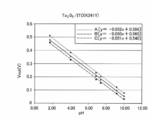
- the dissociation equilibrium of the metal oxide shown in the above-described formula (2) moves according to the hydrogen ion concentration, and the electrode potential is accordingly changed. Since it changes, it becomes a good pH sensor. Therefore, an electrode tip having a metal oxide on its surface is effective in detecting hydrogen ions released as a result of the elongation reaction.
- the oligonucleotide probe 437 which is a single-stranded nucleic acid, is reacted with one base by sequentially reacting dGTP and dTTP. Each of them is extended to form a complex sequentially with the target DNA 440 which is the target nucleic acid. If the surface potential of the electrode does not change regardless of which DNA polymerase is inserted, this means that the base sequence of the target DNA has been analyzed, and the analysis is completed.
- biomolecule detection electrode chip provided with a hairpin aptamer probe and a biomolecule detection method using the same>
- an electrode chip for biomolecule detection provided with a hairpin aptamer probe using an intercalator and ATP (adenosine triphosphate)
- a target biomolecule can be detected with high accuracy.
- the biomolecule detection electrode chip provided with the hairpin aptamer probe is the biomolecule detection electrode described above except that the biomolecule probe provided in the biomolecule detection electrode chip of the present invention is in the form of a hairpin aptamer probe. It is the same as the electrode tip configuration.
- the surface of the electrode substrate on which the biomolecular probe is immobilized has at least one of a metal salt and a metal oxide, the potential stability at the solid-liquid interface between the liquid and the electrode is excellent. Of course, the same.
- the hairpin aptamer probe can induce a large signal by changing the structure upon target recognition in the presence of a reporter molecule (intercalator).
- a reporter molecule intercalator
- an electronic transistor such as an FET as the substrate that constitutes the electrode chip
- the bio-responsible response to external stimuli from biochemical sources is achieved by utilizing the transistor's characteristics such as switching and amplification of specific electrical signals. It is expected to realize a new class of base information processing devices. Details of the biomolecule detection electrode chip provided with the hairpin aptamer probe will be described with reference to FIG.
- FIG. 24 shows a biomolecule detection provided with a hairpin aptamer probe composed of an extended gate FET substrate 610, an electrode substrate 630, a biomolecule probe immobilization material layer 636, and a hairpin aptamer probe 638 (biomolecule probe).
- An electrode tip, an ATP 640, an intercalator 670, and a reference electrode 662 are shown.
- the FET substrate 610, the electrode substrate 630, and the biomolecule probe immobilization material layer 636 are laminated in this order, and the hairpin aptamer probe 638 is immobilized on the biomolecule probe immobilization material layer 636 as a biomolecule probe.
- the FET substrate 610 includes a drain electrode 614D, a source electrode 614S, and a gate electrode 617. By connecting the gate electrode 617 to the electrode substrate 630, a potential change that has changed on the electrode substrate 630 can be obtained.
- the substrate 610 senses.
- the biomolecule probe immobilization material layer 636 is a layer in which the aforementioned biomolecule probe immobilization material is bonded to the electrode substrate 610.
- a dense self-assembled monolayer SAM
- SAM dense self-assembled monolayer
- MCH 6-mercapto-1-hexanol
- a hairpin aptamer probe 638 capable of binding to ATP640 as a biomolecule probe is immobilized on the biomolecule probe immobilization material layer 636.
- the hairpin aptamer probe 638 includes a compound (hereinafter referred to as a specific probe compound) including a structural site 638a capable of forming a structure that can easily enter the intercalator 670 and a structural site 638b including an adenosine 5′-triphosphate (ATP) binding sequence. Also called).
- a structural site having an ATP binding sequence actively binds to ATP and does not react with, for example, GTP (guanosine triphosphate).
- two hairpin aptamer probes 638 are shown.
- One is shown on the left side of FIG. 24 as a short hairpin aptamer probe (sh-aptamer) in which the structural site 638b is a closed loop, and the other is the structural site 638b opened on the right side of FIG. It is shown as a linear aptamer probe in a loop (ln-aptamer).
- sh-aptamer short hairpin aptamer probe
- ln-aptamer probe refers to a biomolecule probe of a biomolecule detection electrode chip equipped with a hairpin aptamer probe, and conformation of both sh-aptamer conformation and ln-aptamer conformation. Shall be included.
- the sh-aptamer is a conformation of a specific probe compound molecule when the structural site 638b containing the ATP binding sequence does not capture ATP, and the ln-aptamer captures the ATP by the structural site 638b containing the ATP binding sequence. This is the conformation of the specific probe compound molecule.
- the structural site 638a forms a layered molecular structure and has a structure in which an intercalator easily enters between layers.
- the structural site 638a in the sh-aptamer is also referred to as “stem”.
- the intercalator is positively charged and has a structure that is linked to the sh-aptamer structural site 638a by electrostatic interaction, ⁇ - ⁇ interaction, or the like.
- the intercalator is represented by DAPI having the following structure.
- a compound is used.
- the hairpin aptamer probe has a positive charge.
- the size of the structural site 638a of the sh-aptamer is preferably 3 nm or less (h ⁇ 3 nm) including the size of the SAM.
- the conformation of the specific probe compound molecule is changed, the structural site 638b containing the ATP binding sequence is opened, and the hairpin aptamer probe 638 captures ATP640. Further, when the structural portion 638b is opened, the intercalator 670 is released from the hairpin aptamer probe 638, and the hairpin aptamer probe 638 loses a positive charge.
- a biomolecule can be recognized by a method without a label using a DNA binding species.
- FIG. 24 shows an example of the structure of specific probe compound molecules constituting the sh-aptamer and ln-aptamer. Note that the structural formula shown in FIG. 24 is a state in which an alkanethiol having 6 carbon atoms and a specific probe compound molecule are bound to each other at the top and bottom, and the 37-mer base sequence site excluding “HS-C6-” It becomes the structure of a specific probe compound molecule.
- C6 refers to an alkyl chain having 6 carbon atoms and represents a part of alkanethiol.
- the c1 portion of the sh-aptamer shown by the 27mer base sequence and the c2 portion of the ln-aptamer correspond to the structural site 638b of the specific probe compound molecule (hairpin aptamer probe 638), which is an ATP binding sequence.
- the sh-aptamer forms a pair when the underlined 7-mer base reacts in a complementary manner, and constitutes a part of the structural site 638a.
- the amount of positive charge lost by the hairpin aptamer probe 638 changing from the sh-aptamer structure to the ln-aptamer structure is converted into a potential difference signal by the field effect of the FET.
- the buffer concentration controls the screening of ions for potential analysis. Real-time measurement of the interfacial potential can be performed with dilution buffer (DPBS is pH 7.4, 15 mM Dulbecco's phosphate buffered saline).
- the difference between the sh-aptamer conformation and the ln-aptamer conformation can be determined by identifying the conformation using an epifluorescence microscope.
- Conformational identification uses indicator dyes (also referred to as fluorescent labels, fluorescent probes, etc.) such as TO-PRO-3.
- the indicator dye may be a known one such as a product manufactured by Beckman-Coulter.
- Biomolecule detection electrode chips 1 and 4 (Examples 1 and 3 respectively) provided with electrodes having AgCl as a metal salt on the metal electrode substrate, and metal salts and metal oxides on the metal electrode substrate
- a biomolecule detection electrode chip 101 (Comparative Example 1) having an electrode from which the metal of the metal electrode substrate was exposed was prepared.
- the metal salt to produce a metal oxide and a Ta 2 O 5 for biomolecules detected with an electrode having an electrode tip 2 (Example 2) on the metal electrodes on the substrate.
- the prescription for producing each biomolecule detection electrode chip is as follows.
- a silver (Ag) plate having a thickness of 90 nm and a surface dimension of 5 mm ⁇ 5 mm was prepared as a metal electrode substrate.
- a glass substrate having a thickness of 1 mm and having the same surface dimensions as the electrode substrate was prepared.
- a titanium (Ti) plate having a thickness of 10 nm and the same surface dimensions as the electrode substrate was prepared. The prepared silver plate, titanium plate, and glass substrate were laminated in this order and bonded to produce an electrode substrate laminate A.
- Electrode substrate laminates A Five prepared electrode substrate laminates A were prepared. Among them, the electrode substrate surfaces of the four electrode substrate laminates A were respectively immersed in the chelate solutions 1 and 2 prepared as described below and dried to obtain surface-treated electrode substrate laminates 1 to 4. .
- Surface treatment electrode substrate laminates 1 and 2 have a contact time between the silver plate and chelate solution 1 of 20 seconds, and surface treatment electrode substrate laminate 3 has a contact time between the silver plate and chelate solution 2 of 180 seconds, In the surface-treated electrode substrate laminate 4, the contact time between the silver plate and the chelate solution 2 was 300 seconds. After each contact time, the surface of each surface-treated electrode substrate was washed with water.
- the surface-treated electrode substrate laminate 1 was prepared by previously immersing the electrode substrate laminate A in a 100 mM NaCl aqueous solution and then adding a 100 mM PDTA ⁇ Fe (III) aqueous solution to start the reaction.
- the surface-treated electrode substrate laminate 2 was prepared by first immersing the electrode substrate laminate A in a 100 mM PDTA ⁇ Fe (III) aqueous solution and then dipping it in a 100 mM NaCl aqueous solution to start the reaction. is there.
- the contact time shown in Table 1 represents the contact time of the PDTA ⁇ Fe (III) aqueous solution.
- SAM laminate Six surface-treated electrode substrate laminates 1 are prepared, and the following SAM-forming solutions 1 to 5 are applied to each of the five electrode substrate surfaces, and a laminate in which SAM is laminated on the electrode substrate laminate (hereinafter “ Also referred to as “SAM laminate”.
- FIG. 8 is a schematic cross-sectional view of the SAM laminate 500, and the SAM laminate 500 includes an electrode substrate laminate 580.
- the SAM laminate 500 includes an electrode substrate laminate 580.
- a glass substrate 510, a titanium plate intermediate layer 520, and a silver plate electrode substrate 532 are laminated in this order.
- a silver chloride layer 534 made of silver chloride (AgCl) and a self-assembled film SAM 536 are formed on the electrode substrate 532 of the electrode substrate laminate 580.
- the silver chloride layer 534 has two regions, and the self-assembled film SAM 536 has three regions.
- a SAM formation comparison solution was applied to the electrode substrate surface of the surface-treated electrode substrate laminate 1 to obtain a comparative laminate 201.
- the details of the preparation formulations of the SAM formation solutions 1 to 5 and the SAM formation comparison solution are as follows.
- Table 3 shows the coating configurations of the SAM laminates 1 to 5 and the comparative laminate 201. Moreover, the coating structure of the SAM laminated body 101 and the SAM laminated body 102 for a comparison mentioned later is also shown.
- the biomolecule probe is formed by allowing the carboxy group of the self-assembled film SAM of the SAM laminate 1 produced as described above to act as an oligonucleotide having an amino group at the 5 ′ end, which is a biomolecule probe, to form an amide bond.
- the biomolecule detection electrode chip 1 of Example 1 was produced.
- the biomolecular probe is immobilized on the self-assembled film SAM in the same manner except that the SAM laminate 101 is used instead of the SAM laminate 1 as the SAM laminate. did. As described above, the biomolecule detection electrode chip 101 of Comparative Example 1 was produced.
- a SAM laminate 102 was fabricated as a comparative SAM laminate.
- the SAM laminate 102 is an electrode substrate laminate A that is not subjected to surface treatment instead of using the surface-treated electrode substrate laminate 1 as an electrode substrate laminate.
- a self-assembled film SAM was formed on the electrode substrate in the same manner except that was used.
- the SAM laminated body 102 which is a comparative self-assembled film SAM-containing electrode substrate laminated body was produced.
- Types of SAM laminates and SAM concentrations used in biomolecule detection electrode chip 1 and biomolecule detection electrode chip 101, and types of surface treatment of electrode substrate laminate A used in the preparation of SAM laminates Table 4 summarizes the surface morphology ("surface species" column).
- FIGS. 9 to 13 show the results of formation of metal salt layer.
- FIG. 9 is an AFM photograph of the electrode substrate surface of the electrode substrate laminate A, that is, the surface of the silver plate.
- FIGS. 10 to 13 show the electrode substrate surface and the silver chloride of the surface-treated electrode substrate laminates 1 to 4, respectively. It is an AFM photograph of the layer surface. In the photograph shown in FIG. 9, no white area is observed, but in FIGS.
- a white area is observed.
- Such a white region is considered to be AgCl, and the area of the white region increases as the sodium chloride concentration increases and the contact time between the silver plate and the chelate solution increases, and AgCl is formed on the silver plate.
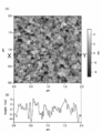
- the vertical and horizontal axes of the AFM photographs shown in FIGS. 9 to 13 indicate the size of the observation region, and the unit is [ ⁇ m].
- the band-shaped scale located on the right side of the AFM photograph indicates the size of the irregularities on the surface of the electrode substrate or the surface of the silver chloride layer, and the numerical values are given according to the gradation from white to black.
- the unit of the band-shaped scale is [nm].
- the vertical axis represents current [A] and the horizontal axis represents potential [V].
- a curved line A indicated by a solid line and a curved line B indicated by a broken line show the CV characteristics of two electrode chips produced under the same conditions. Both the curve A and the curve B have two minimum peaks in the lower curve that appears when the potential is swept in the positive direction. Among these, a small peak shown in the vicinity of ⁇ 1100 [V] indicates the presence of Ag—S bonds in the SAM laminate.
- the horizontal axis of the XPS spectrum indicates the binding energy [eV], and the vertical axis indicates the number of photoelectrons [c / s (counts / sec)].
- Each of the SAM laminates 1, 3, 5 and the comparative laminate 201 uses the surface-treated electrode substrate laminate 1 in which the surface of the electrode substrate laminate A is surface-treated with a chelate solution as the electrode substrate laminate. Therefore, silver chloride is formed on the surface of the surface-treated electrode substrate laminate 1.
- the XPS spectrum shown in FIG. 15 shows the abundance of chlorine atoms (Cl) contained in the silver electrode surfaces of the SAM laminates 1, 3, 5 and the comparative laminate 201. The higher the amount, the greater the peak height.
- the curve A of the SAM laminate 1 having a large SAM concentration has a low peak indicating the abundance of chlorine atoms, and the peak increases as the SAM concentration decreases. It has become. This is because as the SAM concentration increases, the number of sulfur bound to the silver surface increases, and the proportion of the area occupied by the SAM in the substrate surface increases. Since the silver chloride layer is formed by chemical treatment after the SAM is formed, the silver chloride layer is formed in the remaining portion where the SAM is not formed. Therefore, the SAM concentration dependency as shown in FIG. 15 is observed.
- the SAM laminates 1, 3, 5 are obtained by applying a SAM forming solution having a SAM concentration shown in Table 5 to the surface-treated electrode substrate laminate 1.
- the SAM formation solution contains alkanethiol (a biomolecule probe solidifying material) having a sulfur atom.
- the comparative laminate 201 is obtained by applying a SAM formation comparison solution containing no alkanethiol and having a SAM concentration of 0 ⁇ mol / L to the surface-treated electrode substrate laminate 1.
- the XPS spectrum shown in FIG. 16 shows curves AC having peaks indicating the presence of sulfur atoms (S) contained in the SAM laminates 1, 3, and 5, and the laminate 201 For, no curve with peaks was obtained.
- the curve A of the SAM laminate 1 with a high SAM concentration has a higher peak, and the peak is lower as the SAM concentration is lower. This is because as the SAM concentration increases, the number of sulfur bonded to the silver surface increases, and the proportion of the area occupied by the SAM in the substrate surface increases.
- the table shown in FIG. 17 shows the ratio of detected atoms obtained from the XPS spectra shown in FIGS.
- the unit of each numerical value is [%].
- Atoms detected by XPS analysis include carbon atoms (C), chlorine atoms (Cl), oxygen atoms (O), and sulfur atoms (S). It is considered that the carbon atom is derived from the hydrocarbon chain of alkanethiol constituting the self-assembled film SAM, and the sulfur atom is derived from the thiol of alkanethiol.
- the chlorine atom is considered to be derived from chloride ions in the silver chloride layer.
- oxygen atoms are derived from moisture in the air attached to the electrode substrate.
- “1 ⁇ M”, “5 ⁇ M”, and “10 ⁇ M” in the Sample column are the concentrations of the SAM forming solution when forming the SAM laminate.
- bare Ag in the Sample column is a laminate obtained by using the surface-treated electrode substrate laminate 1 in which the AgCl surface is exposed without forming the SAM. Represents the body 201.
- bare Ag the slight detection of the presence of carbon atoms is considered to be derived from ethanol constituting the SAM formation comparison solution applied to the surface-treated electrode substrate laminate 1.
- the stability of the surface potential on the electrode substrate surface was evaluated.
- the SAM laminate 4 and the SAM laminate 102 are both produced using the SAM forming solution 4 having a SAM concentration of 3 ⁇ mol / L.
- the electrode substrate laminate to which the SAM forming solution 4 is applied is subjected to surface treatment in the SAM laminate 4 to form AgCl, and the SAM laminate 102 is not subjected to surface treatment and the Ag plate is exposed. .
- the surface potential was measured by using a 6514 type electrometer manufactured by Keithley as a potential measuring device, and using sodium / silver chloride reference electrodes immersed in a saturated potassium chloride solution as a standard, sodium chloride having a concentration of 2.5 mM, 25 mM, and 250 mM. The solution was used. The results are shown in FIGS.
- FIG. 18 shows changes over time in the surface potentials on the electrode substrate surface of six identical SAM laminates 4 produced using the surface-treated electrode substrate laminate 1 having a silver chloride layer formed on the electrode substrate surface (A1 to A6). ).
- FIG. 19 shows the time variation (B1 to B8) of the surface potential on the electrode substrate surface of eight identical SAM laminates 102 produced using the electrode substrate laminate A with the silver plate exposed on the electrode substrate surface. It is a graph. In both FIG. 18 and FIG. 19, the vertical axis represents the surface potential [V], and the horizontal axis represents the elapsed time [second]. The surface potential is measured by replacing the solution soaked with 25 mM sodium chloride and alternately with 250 mM sodium chloride.
- the SAM laminate 4 in which the silver chloride layer is formed on the electrode substrate surface has a stable surface potential in 5 to 200 seconds, often about 30 seconds from the start of measurement of the surface potential. ing.
- the surface potential is not stable and potential drift occurs.
- FIG. 20 a graph showing variations in the surface potential of the SAM laminate 4 and the SAM laminate 102 is shown in FIG.
- the vertical axis represents the surface potential [V] on the electrode substrate surface of the SAM laminate
- the horizontal axis represents the concentration [mol / L] of sodium chloride (NaCl) used for the measurement.
- the curve A representing the surface potential of the SAM laminate 4 having a silver chloride layer on the electrode substrate has a small length of the vertical bar indicating the variation in the surface potential, and the potential stability of the surface potential. Is excellent. This is presumably because the silver chloride of the silver chloride layer formed on the electrode substrate is dissociated and is in an equilibrium state in the aqueous solution.
- the curve B representing the surface potential of the SAM laminate 102 formed by using the electrode substrate on which the silver plate is exposed has a large vertical bar indicating the variation in the surface potential, and the surface potential is It turns out that it is not stable.
- the surface potential changes according to the sodium chloride concentration of the immersed solution, and the larger the sodium chloride concentration, the smaller the surface potential itself and the smaller the surface potential variation.
- the electrode potential has a negative slope with respect to the anion (chlorine ion) and is proportional to the logarithm of the ion concentration. From FIG. 20, the electrode having silver chloride formed on the surface has good linearity with respect to the logarithm of the chlorine ion concentration, and the surface potential based on the electrochemical equilibrium described by the Nernst equation is obtained. It is possible to control the surface potential.
- an electrode with silver exposed on the surface shows a non-linear response, and it is assumed that the surface potential is changed by other mechanisms such as physical adsorption of ions.
- a self-assembled film SAM was formed on the silver surface by allowing alkanethiol having a carboxyl terminus dissolved in ethyl alcohol to act on the surface of the electrode chip where silver was exposed at a concentration of 1 ⁇ mol / L ( ⁇ M). Thereafter, the electrode tip was immersed in a mixed solution of 100 mM 1,3-diaminopropanetetraacetic acid / iron / ammonium / monohydrate [PDTA / Fe (III)] and 100 mM sodium chloride (NaCl) for 20 seconds, Silver chloride was formed on the surface of the silver where no SAM was formed.
- an amide bond is formed between the amino group on the electrode surface and the carboxyl group of the oligonucleotide, thereby Immobilized on the electrode surface.
- the electrode potential changed about 10 mV in the negative direction. This is presumably because the target DNA having a negative charge formed a complementary strand bond with the oligonucleotide on the electrode surface. As described above, it was confirmed that the target DNA can be detected with the biomolecule detection electrode chip of the present invention.
- Electrode substrate laminate As an electrode substrate, an ITO substrate having a thickness of 100 nm and a surface dimension of 5 mm ⁇ 5 mm was prepared. As a substrate for supporting the electrode substrate, a glass substrate having a thickness of 1 mm and having the same surface dimensions as the electrode substrate was prepared. The prepared ITO substrate and a glass plate were adhered to produce an electrode substrate laminate T for the biomolecule detection electrode chip 2.
- Electrode substrate laminates T are prepared, and the surface of the electrode substrate is subjected to electron beam evaporation using tantalum oxide (Ta 2 O 5 ), and a metal oxide layer containing a deposited film with a thickness of 20 nm is contained. An electrode substrate laminate 5 was obtained.
- the biomolecule probe was immobilized in the same manner except that the SAM laminate 1 was used instead of the SAM laminate 1 as the SAM laminate.
- enzyme urease was used as a biomolecule.
- the biomolecule detection electrode tip 2 of Example 2 was produced. Table 7 shows the configuration of the SAM laminate 6 used in the biomolecule detection electrode chip 2.
- the vertical axis indicates the size of the surface unevenness [nm]
- the horizontal axis indicates the AFM.
- the same observation area size [ ⁇ m] as the horizontal axis of the photograph is shown.
- the horizontal axis of the AFM photograph shown on the (A) side and the horizontal axis shown on the (B) side are shown in correspondence with each other. From FIG. 21, the average roughness R RMS of the tantalum oxide layer surface was 1.855 nm, and it was found that a uniform and flat film was obtained.
- aqueous solutions having six different pH values of pH 1.68, pH 4.01, pH 6.86, pH 7.41, pH 9.18, and pH 10.1 were prepared.
- the metal oxide layer-containing electrode substrate laminate 5 was immersed in each of the prepared liquid aqueous solutions, and the change over time in the surface potential of the surface of the metal oxide layer-containing electrode substrate laminate 5 was measured for about 100 seconds immediately after the immersion. .
- the metal oxide layer-containing electrode substrate laminate 5 has an aqueous solution of pH 1.68, an aqueous solution of pH 4.01, an aqueous solution of pH 6.86, an aqueous solution of pH 7.41, an aqueous solution of pH 9.18, and an aqueous solution of pH 10.1.
- the soaking was repeated 3 times.
- the metal oxide layer-containing electrode substrate laminate 5 is taken out of the aqueous solution and immersed in the next aqueous solution, the metal oxide layer-containing electrode substrate laminate 5 is washed with water and dried, and then the next aqueous solution is used. Soaked in.
- the variation in surface potential on the surface of each metal oxide layer when the metal oxide layer-containing electrode substrate laminate 5 was placed in various pH environments was evaluated.
- the surface potential measurement was performed by connecting the metal oxide layer-containing electrode substrate laminate 5 to a 6514 type electrometer manufactured by Keithley, based on a silver-silver chloride reference electrode.
- FIG. 22 The measurement results are shown in FIG. In FIG. 22, the vertical axis represents the surface potential [V] and the horizontal axis the time change [second].
- A1 to a3 shown above the arrows ( ⁇ ) represent changes in surface potential in an aqueous solution at pH 1.68
- b1 to b3 represent changes in surface potential in an aqueous solution at pH 4.01
- c1 to c3 Represents the change in the surface potential in the aqueous solution at pH 6.86
- d1 to d3 represent the change in the surface potential in the aqueous solution at pH 7.41
- e1 to e3 represent the surface potential in the aqueous solution at pH 9.18.
- F1 to f3 represent changes in the surface potential in an aqueous solution with a pH of 10.1.
- a straight line A in FIG. 23 is a regression line of the surface potential plotted against the pH of a1 to f1 in FIG. 22, and a straight line B is a regression line of the surface potential plotted against the pH of a2 to f2 in FIG.
- a straight line C is a regression line obtained by plotting the surface potential with respect to pH of a3 to f3 in FIG.
- FIG. 23 shows that a good linear response is exhibited in a wide pH range from pH 1.68 to pH 10.1.
- the slopes of the regression lines A to C shown in FIG. 23 are referred to as slope sensitivity and serve as an index for evaluating the performance as a metal oxide film material and a pH sensor.
- the relationship between the surface potential and pH is expressed by the Nernst equation. According to this, the slope sensitivity is about 58 mV / pH at room temperature.
- the slopes of the three regression lines shown in FIG. 23 are ⁇ 0.052 V / pH, ⁇ 0.050 V / pH, and ⁇ 0.051 V / pH, respectively, and the reproducibility and uniformity are good.
- urea was detected according to the following prescription.
- Urea is an important biochemical component in evaluating renal function. Urea is decomposed as shown in the following formula (3) by the catalytic action of the enzyme urease.
- the aqueous solution hydrogen ion concentration that is, pH changes. Therefore, the urea concentration as the measurement target can be known by measuring the pH change.
- the surface potential of the electrode chip changed about 15 mV in 1 minute after introduction. This is because urease immobilized on the electrode surface reacts with urea in the solution to be measured, and hydrogen ions are consumed according to the formula (3). It is thought that it was possible to detect with the oxide electrode.
- the SAM forming solution 6 was prepared by using 6-Carboxy-1-decanthiol instead of using 10-Carboxy-1-decanthiol as the biomolecular probe immobilization material. -Prepared similarly except using Mercapto-1-hexanol (MCH).
- MCH Mercapto-1-hexanol
- a probe compound having a 37-mer base sequence shown as an example of the sh-aptamer structure in FIG. 24 was prepared.
- the hairpin aptamer probe was immobilized on the SAM laminate 6 by allowing the carboxyl group of the probe compound to act on the hydroxy group of the self-assembled film SAM of the SAM laminate 6 to form an ester bond.
- the biomolecule detection electrode chip 3 was produced.
- the hairpin aptamer probe provided in the biomolecule detection electrode tip 3 immersed in the DPBS dilution buffer does not contain ATP in the DPBS dilution buffer before the addition of the ATP aqueous solution. It is thought that he is taking a formation.
- DAPI aqueous solution containing DAPI (intercalator) was added to a container in which biomolecule detection electrode chip 3 (sh-aptamer) was immersed in a DPBS dilution buffer. Thereafter, an ATP aqueous solution was added, and the potential difference when the ATP aqueous solution was added was measured. Next, after washing the biomolecule detection electrode chip 3 with the DPBS dilution buffer, a container in which the biomolecule detection electrode chip 3 (sh-aptamer) is immersed in the DPBS dilution buffer is prepared separately, and the DAPI aqueous solution is stored in the container. Added to. Thereafter, an aqueous solution of GTP was added, and the potential difference when the aqueous solution of GTP was added was measured. The results are shown in FIG.
- the carboxy group of the probe compound having the ln aptamer structure shown in FIG. 24 was allowed to act on the hydroxy group of the self-assembled film SAM of the SAM laminate 6 in the same manner.
- the biomolecule detection electrode chip 4 in which the ln aptamer was immobilized on the SAM laminate 6 was produced.
- the potential measurement 1 when the ATP aqueous solution was added in the same manner except that the obtained biomolecule detection electrode tip 4 (In aptamer) was used instead of the biomolecule detection electrode tip 3 (sh-aptamer) And the potential difference when the GTP aqueous solution was added were measured. The results are shown in FIG.
- the linear (ln) aptamer Since the linear (ln) aptamer has an ATP binding sequence, it has a function of capturing the target ATP, but the electrode connected to the ln aptamer could not detect ATP (FIG. 27). This is thought to be due to the fact that ATP is electrically neutral in the DPBS dilution buffer at pH 7.4, so that no significant signal is generated by detection of ATP using the FET. Conceivable. Therefore, both the sh-aptamer setting and DAPI need to generate a measurement signal.
- FET devices can convert the intrinsic charge of molecules in the electric double layer.
- the characteristic device cleaning length of the solution can be described as a function of ionic strength (I) as ( ⁇ ) ⁇ ⁇ I 1/2 .
- the Debye length calculated in 15 mM DPBS dilution buffer was 2.5 nm. This corresponds to an intramolecular distance of only 7 mer at the 5 ′ end of the sh-aptamer within the Debye length when converted from the base base length (0.34 nm).
- FET devices are believed to respond sensitively only to stem charge changes due to DAPI dissociation upon capture of a particular ATP.
- FIG. 28 shows an epifluorescent image of the surface (AgCl surface) of the electrode substrate on which the SAM and hairpin aptamer probe are not formed
- FIG. 29 shows a state before ATP is allowed to act on the biomolecule detection electrode chip 3 (sh-aptamer).
- FIG. 30 shows an epifluorescent image after ATP was allowed to act on the biomolecule detection electrode chip 3 (sh-aptamer).
- FIG. 29 shows that the hairpin aptamer probe had a closed-loop sh-aptamer conformation.
- FIG. 30 showing the system in the presence of ATP, fluorescence emission is not observed, and the hairpin aptamer probe has a conformation different from that of the sh-aptamer, that is, the conformation of the ln-aptamer. Recognize.
- An FET is a powerful transducer for detecting ions and charged particles as a potential difference signal in an unlabeled manner. Also, the expanded gate structure configuration facilitates sensor chip changes in a cost effective manner. However, high sensitivity detection of weakly charged or uncharged analytes has been a major issue.
- the use of structured oligonucleotide aptamer probes of molecular recognition elements in combination with groove binding or intercalating species can expand the use of FET sensors to detect a wide variety of neutral molecules. In the future, DAPI can be improved by improving the safety of the assay and using a DNA binder with less carcinogenicity.
- the critical signal induced by the release of the charge indicator from the electrical double layer at the gate solution nanointerface overcomes the potential drawback of ion screening for analytes charged to FET biosensing Is expected to do.
- Each approach described in the present invention may be detected using a target-specific sh-aptamer in combination with the built-in charge of the shield and a large molecular cationic groove binder.
- DAPI cationic indicator
- the large change obtained as a potentiometric signal was induced by the dissociation of preloaded DAPI from target-induced self-denaturation and the hairpin trunk of the electric double layer by the formation of aptamer and ATP complexes.
- the structured aptamer concept allows FET biosensors to detect neutral analytes with minimal impact from the length of device cleaning.
- the hairpin aptamer combined with the function of the FET is expected to play a role as a general switch for transmitting ATP recognition to an electric signal.
- Electrode substrate laminate C in which a glass substrate, a titanium film, and a silver film were laminated in this order was produced in the following manner.
- a synthetic quartz glass substrate having a thickness of 1 mm and a size of 100 mm ⁇ 100 mm was prepared.
- the surface of the synthetic quartz glass substrate was cleaned by (1) reverse sputtering, (2) a titanium (Ti) film was deposited by vapor deposition, and (3) silver (Ag) was further formed on the obtained Ti film.
- a film was formed by vapor deposition. The Ti film was formed to improve the adhesion between the synthetic quartz glass substrate and the Ag film.
- the Ti film of the electrode substrate laminate C was 10 nm thick, and the Ag film was 90 nm thick.
- the sputtering conditions (1) to (3) are as follows.
- As the sputtering apparatus a sputtering apparatus “Jsputter” was used.
- SAM-forming solution 7 containing 10-Carboxy-1-decanthiol (10-CDT) (Dojindo Laboratories) and Sulfobetaine 3-undecanethiol (SB) into the electrode substrate surface of the electrode substrate laminate C, A SAM laminate 7 was formed on the electrode substrate surface.
- the SAM-forming solution 7 was prepared in the same manner as the SAM-forming solution 1 except that Sulfobetaine 3-undecanethiol was further mixed.
- a chelate solution (chelate solution 1) containing PDTA ⁇ Fe (III) (Cylest Killest PD-FN Sample) (PDTA ferric ammonium complex) is applied to the electrode substrate surface of the produced SAM laminate 7, A silver chloride layer was formed.
- chelate solution 1 containing PDTA ⁇ Fe (III) Cylest Killest PD-FN Sample
- PDTA ferric ammonium complex is applied to the electrode substrate surface of the produced SAM laminate 7, A silver chloride layer was formed.
- substrate laminated body 6 which contains SAM containing SB and silver chloride on the surface was obtained.
- an oligonucleotide having an amino group at the 5 ′ end which is a biomolecule probe (DNA probe) was allowed to act on the carboxy group of the self-assembled membrane SAM to form an amide bond, thereby immobilizing the biomolecule probe.
- the biomolecule detection electrode chip 4 of Example 3 was produced.
- the SAM contains hydrophobic 10-Carboxy-1-decanthiol and hydrophilic sulfobetaine 3-undecanethiol (SB)
- all the ends of the SAM are biomolecule probes.
- a part is a biomolecular probe and a part is SB.
- the molar ratio of DNA probe to SB [DNA probe: SB] is 1: 1 and 0.04 probe / (nm) 2 .
- the metal salt layer-containing electrode substrate laminate 6 is the electrode substrate having the pattern shown in FIGS. 2 and 3 described above, and has 10 circular electrode substrates on the surface (the electrode substrates in FIGS. 2 and 3). 130c) and a rectangular electrode substrate (corresponding to the electrode substrate 130a in FIGS. 2 and 3). Each of the circular electrode substrates has a diameter of 500 ⁇ m.
- the SAM containing SB formed in the above process and the silver chloride layer are formed.
- the circular electrode substrate and the rectangular electrode substrate are connected by a linear electrode substrate 130b as shown in FIGS.
- a glass cylinder that surrounds all of the 10 circular electrode substrates and can be disposed outside the enclosure is disposed on the surface of the metal salt layer-containing electrode substrate laminate 6,
- the cylinder was glued so as not to leak water to form a cylindrical container having a bottom surface with a surface having ten circular electrode substrates.
- the biomolecule detection electrode chip 4 comes into contact with the 10 circular electrode substrates and does not come into contact with the rectangular electrode substrate. It has a configuration.
- control sample which is the sample (2)
- the target sample which is sample (3), is a liquid obtained by diluting a PCR product (PCR products) containing microRNA-143 amplified by adding microRNA-143 to the PCR buffer and performing 30 thermal cycles. is there.
- Each sample of (1), (2), and (3) was dropped onto the circular electrode substrate in the cylindrical container of the biomolecule detection electrode chip 4 at the time interval shown in FIG. Specifically, the sample (1) in FIG. 31 (1), the sample (2) in (2) in FIG. 31, and the sample (3) in (3) in FIG. 31 are dropped three times on the electrode substrate. Each sample was contacted. In addition, the surface potential of each electrode substrate was read at time points (A) and (B) in FIG. The reading of the surface potential at time (A) was performed after dropping the sample (2) (control sample) onto the electrode substrate and washing the electrode with a buffer. Further, the reading of the surface potential at the time (B) was performed after dropping the sample (3) (target sample) onto the electrode substrate and washing the electrode with a buffer. The results are shown in FIG. 31 and FIG.
- FIG. 31 is a graph showing the temporal change of the surface potential in the evaluation of the stability of the surface potential of the biomolecule detection electrode tip 4.
- the electrode chip for biomolecule detection since the surface potential settles immediately after the addition of each sample of (1), (2), and (3), and the baseline is hardly changed, the electrode chip for biomolecule detection It can be seen that if the electrode substrate of 4 is used, stable surface potential difference measurement can be performed. Since the biomolecule detection electrode chip 4 has ten circular electrode substrates capable of detecting biomolecules, the surface potential due to biomolecule adsorption was measured on each of the ten electrode substrates. FIG. 31 shows one of the data, but the same tendency was observed in the other nine electrode substrates.
- FIG. 32 is a bar graph showing the average of surface potentials read at (A) time point and (B)) in FIG.
- the surface potential of the control sample that is, the PCR buffer is read
- the surface potential of the target sample is read.
- the bar graph shown on the left (C) is the surface potential when the control sample (Control) is brought into contact with the electrode substrate
- the bar graph shown on the right (T) shows the target sample including the target as an electrode. The surface potential when brought into contact with the substrate.
- the bar graph of FIG. 32 also shows an error bar indicating measurement variation.
- the sizes of the error bars shown in (C) and (T) are both about 1 mV, indicating that the variation is small.
- a small error bar indicates that the surface potential is stable.
- Electrode substrate 34 Inorganic layer (metal salt and metal At least one of the oxides) 36: Biomolecule probe immobilization layer 38: Biomolecule probe 100: Biomolecule detection electrode chip 110: Glass substrate 130: Electrode substrate 130a: Rectangular electrode substrate 130b: Linear electrode substrate 130c: Circular electrode substrate 200 : Laminate 202: laminate 333a: electrode substrate 333b: electrode substrate 334a: part of metal salt 334b: part of metal salt 336a: biomolecular probe immobilization material 336b: biomolecule probe immobilization material 338: biomolecule probe 362: reference electrode 364a: operational amplifier 364b: operational amplifier 366: operational amplifier 368: differential amplification output 370: aqueous biomolecule solution 432: electrode substrate 437: oligonucle
Landscapes
- Health & Medical Sciences (AREA)
- Life Sciences & Earth Sciences (AREA)
- Chemical & Material Sciences (AREA)
- Molecular Biology (AREA)
- Physics & Mathematics (AREA)
- Chemical Kinetics & Catalysis (AREA)
- Spectroscopy & Molecular Physics (AREA)
- Electrochemistry (AREA)
- Analytical Chemistry (AREA)
- Biochemistry (AREA)
- General Health & Medical Sciences (AREA)
- General Physics & Mathematics (AREA)
- Immunology (AREA)
- Pathology (AREA)
- Microelectronics & Electronic Packaging (AREA)
- Engineering & Computer Science (AREA)
- Apparatus Associated With Microorganisms And Enzymes (AREA)
Abstract
Priority Applications (3)
| Application Number | Priority Date | Filing Date | Title |
|---|---|---|---|
| US14/112,383 US20140124383A1 (en) | 2011-04-20 | 2012-04-20 | Electrode chip for detecting biological molecule, and method for detecting biological molecule |
| JP2013511073A JPWO2012144631A1 (ja) | 2011-04-20 | 2012-04-20 | 生体分子検出用電極チップ、及び、生体分子検出方法 |
| EP12774527.1A EP2700937A4 (fr) | 2011-04-20 | 2012-04-20 | Puce à électrode destinée à détecter une molécule biologique, et procédé de détection d'une molécule biologique |
Applications Claiming Priority (2)
| Application Number | Priority Date | Filing Date | Title |
|---|---|---|---|
| JP2011094452 | 2011-04-20 | ||
| JP2011-094452 | 2011-04-20 |
Publications (1)
| Publication Number | Publication Date |
|---|---|
| WO2012144631A1 true WO2012144631A1 (fr) | 2012-10-26 |
Family
ID=47041731
Family Applications (1)
| Application Number | Title | Priority Date | Filing Date |
|---|---|---|---|
| PCT/JP2012/060785 WO2012144631A1 (fr) | 2011-04-20 | 2012-04-20 | Puce à électrode destinée à détecter une molécule biologique, et procédé de détection d'une molécule biologique |
Country Status (4)
| Country | Link |
|---|---|
| US (1) | US20140124383A1 (fr) |
| EP (1) | EP2700937A4 (fr) |
| JP (1) | JPWO2012144631A1 (fr) |
| WO (1) | WO2012144631A1 (fr) |
Cited By (2)
| Publication number | Priority date | Publication date | Assignee | Title |
|---|---|---|---|---|
| JP2017044674A (ja) * | 2015-08-28 | 2017-03-02 | 国立大学法人 東京大学 | 電極、センサー、流体デバイスおよび電極の製造方法 |
| WO2018070113A1 (fr) * | 2016-10-14 | 2018-04-19 | ソニーセミコンダクタソリューションズ株式会社 | Substrat de détection de potentiel et dispositif de mesure de potentiel |
Families Citing this family (3)
| Publication number | Priority date | Publication date | Assignee | Title |
|---|---|---|---|---|
| US20180238867A1 (en) * | 2015-10-30 | 2018-08-23 | Nec Solution Innovators, Ltd. | Detection device and target detection method using the same |
| US10983088B2 (en) * | 2016-03-28 | 2021-04-20 | University Of Massachusetts | Coulometric microfluidic sensors using a silver band electrode, and methods thereof |
| WO2018112458A1 (fr) * | 2016-12-16 | 2018-06-21 | Infusense Corp. | Compositions et procédés pour détecter des molécules dans un échantillon |
Citations (3)
| Publication number | Priority date | Publication date | Assignee | Title |
|---|---|---|---|---|
| JP2005077210A (ja) | 2003-08-29 | 2005-03-24 | National Institute For Materials Science | 生体分子検出素子及びそれを用いた核酸解析方法 |
| JP2008064724A (ja) * | 2006-09-11 | 2008-03-21 | Osaka Univ | カーボンナノチューブ電極及び当該電極を用いたセンサー |
| JP2011094452A (ja) | 2009-11-02 | 2011-05-12 | Allen:Kk | スラブ式軌道における補修方法 |
Family Cites Families (3)
| Publication number | Priority date | Publication date | Assignee | Title |
|---|---|---|---|---|
| KR100682918B1 (ko) * | 2005-01-20 | 2007-02-15 | 삼성전자주식회사 | 표면 개질을 갖는 fet형 바이오 센서 |
| KR100738081B1 (ko) * | 2005-11-22 | 2007-07-12 | 삼성전자주식회사 | 무기막을 구비하는 fet 기반 바이오 센서, 그의 제조방법 및 그를 이용한 생분자 검출 방법 |
| KR101478540B1 (ko) * | 2007-09-17 | 2015-01-02 | 삼성전자 주식회사 | 트랜지스터의 채널로 나노 물질을 이용하는 바이오 센서 및그 제조 방법 |
-
2012
- 2012-04-20 WO PCT/JP2012/060785 patent/WO2012144631A1/fr active Application Filing
- 2012-04-20 US US14/112,383 patent/US20140124383A1/en not_active Abandoned
- 2012-04-20 JP JP2013511073A patent/JPWO2012144631A1/ja active Pending
- 2012-04-20 EP EP12774527.1A patent/EP2700937A4/fr not_active Withdrawn
Patent Citations (3)
| Publication number | Priority date | Publication date | Assignee | Title |
|---|---|---|---|---|
| JP2005077210A (ja) | 2003-08-29 | 2005-03-24 | National Institute For Materials Science | 生体分子検出素子及びそれを用いた核酸解析方法 |
| JP2008064724A (ja) * | 2006-09-11 | 2008-03-21 | Osaka Univ | カーボンナノチューブ電極及び当該電極を用いたセンサー |
| JP2011094452A (ja) | 2009-11-02 | 2011-05-12 | Allen:Kk | スラブ式軌道における補修方法 |
Non-Patent Citations (2)
| Title |
|---|
| NATURE BIOTECHNOLOGY, vol. 16, 1998, pages 27,40 |
| See also references of EP2700937A4 |
Cited By (2)
| Publication number | Priority date | Publication date | Assignee | Title |
|---|---|---|---|---|
| JP2017044674A (ja) * | 2015-08-28 | 2017-03-02 | 国立大学法人 東京大学 | 電極、センサー、流体デバイスおよび電極の製造方法 |
| WO2018070113A1 (fr) * | 2016-10-14 | 2018-04-19 | ソニーセミコンダクタソリューションズ株式会社 | Substrat de détection de potentiel et dispositif de mesure de potentiel |
Also Published As
| Publication number | Publication date |
|---|---|
| US20140124383A1 (en) | 2014-05-08 |
| JPWO2012144631A1 (ja) | 2014-07-28 |
| EP2700937A1 (fr) | 2014-02-26 |
| EP2700937A4 (fr) | 2014-09-03 |
Similar Documents
| Publication | Publication Date | Title |
|---|---|---|
| Pejcic et al. | Impedance spectroscopy: Over 35 years of electrochemical sensor optimization | |
| Karunakaran et al. | Introduction to biosensors | |
| Mishra et al. | Electrochemical impedance spectroscopy characterization of mercaptopropionic acid capped ZnS nanocrystal based bioelectrode for the detection of the cardiac biomarker—myoglobin | |
| LaFratta et al. | Very high density sensing arrays | |
| KR20180054558A (ko) | 생체분자 센서들 및 방법들 | |
| Riedel et al. | Impedimetric DNA Detection Steps Forward to Sensorial Application | |
| Brazaca et al. | Nanostructured materials and nanoparticles for point of care (POC) medical biosensors | |
| WO2012144631A1 (fr) | Puce à électrode destinée à détecter une molécule biologique, et procédé de détection d'une molécule biologique | |
| Veloso et al. | Electrochemical biosensors for medical applications | |
| Wain et al. | Scanning electrochemical microscopy imaging of DNA microarrays using methylene blue as a redox-active intercalator | |
| Bronder et al. | Detection of PCR-amplified tuberculosis DNA fragments with polyelectrolyte-modified field-effect sensors | |
| Chen et al. | Ultrasensitive electrochemical DNA biosensor fabrication by coupling an integral multifunctional zirconia-reduced graphene oxide-thionine nanocomposite and exonuclease I-assisted cleavage | |
| Zacco et al. | Electrochemical biosensing based on universal affinity biocomposite platforms | |
| WO2013176289A1 (fr) | Dispositif de détection d'une molécule biologique et procédé de détection d'une molécule biologique | |
| Yılmaz et al. | An epoxysilane modified indium tin oxide electrode for the determination of PAK 2: application in human serum samples | |
| Ma et al. | Sensitive PAT gene sequence detection by nano-SiO2/p-aminothiophenol self-assembled films DNA electrochemical biosensor based on impedance measurement | |
| KR100728152B1 (ko) | 표적 물질의 검출 또는 정량 방법, 그 방법에 사용되는전극 기판, 장치, 및 키트 | |
| Sopousek et al. | Blocking the nanopores in a layer of nonconductive nanoparticles: dominant effects therein and challenges for electrochemical impedimetric biosensing | |
| JP2003090815A (ja) | 遺伝子の電気化学的検出方法と核酸チップ | |
| Fatima et al. | Biosensors | |
| Wang et al. | Molecular-electromechanical system for unamplified detection of trace analytes in biofluids | |
| Barreiros Dos Santos et al. | Fundamentals of biosensors and detection methods | |
| JP4111961B2 (ja) | Dna固定化fetセンサ及びその作製方法 | |
| Devadhasan et al. | Overview of CMOS image sensor use in molecular diagnostics | |
| KR101048478B1 (ko) | 극미량 시료 검출용 바이오센서 및 그 제조방법 |
Legal Events
| Date | Code | Title | Description |
|---|---|---|---|
| 121 | Ep: the epo has been informed by wipo that ep was designated in this application |
Ref document number: 12774527 Country of ref document: EP Kind code of ref document: A1 |
|
| ENP | Entry into the national phase |
Ref document number: 2013511073 Country of ref document: JP Kind code of ref document: A |
|
| NENP | Non-entry into the national phase |
Ref country code: DE |
|
| WWE | Wipo information: entry into national phase |
Ref document number: 14112383 Country of ref document: US Ref document number: 2012774527 Country of ref document: EP |