WO2012144507A1 - 制御装置、通信機器、ネットワークシステム、ネットワーク管理方法、およびプログラム - Google Patents
制御装置、通信機器、ネットワークシステム、ネットワーク管理方法、およびプログラム Download PDFInfo
- Publication number
- WO2012144507A1 WO2012144507A1 PCT/JP2012/060417 JP2012060417W WO2012144507A1 WO 2012144507 A1 WO2012144507 A1 WO 2012144507A1 JP 2012060417 W JP2012060417 W JP 2012060417W WO 2012144507 A1 WO2012144507 A1 WO 2012144507A1
- Authority
- WO
- WIPO (PCT)
- Prior art keywords
- communication
- communication device
- devices
- network
- control device
- Prior art date
- Legal status (The legal status is an assumption and is not a legal conclusion. Google has not performed a legal analysis and makes no representation as to the accuracy of the status listed.)
- Ceased
Links
Images








Classifications
-
- H—ELECTRICITY
- H04—ELECTRIC COMMUNICATION TECHNIQUE
- H04W—WIRELESS COMMUNICATION NETWORKS
- H04W84/00—Network topologies
- H04W84/18—Self-organising networks, e.g. ad-hoc networks or sensor networks
-
- Y—GENERAL TAGGING OF NEW TECHNOLOGICAL DEVELOPMENTS; GENERAL TAGGING OF CROSS-SECTIONAL TECHNOLOGIES SPANNING OVER SEVERAL SECTIONS OF THE IPC; TECHNICAL SUBJECTS COVERED BY FORMER USPC CROSS-REFERENCE ART COLLECTIONS [XRACs] AND DIGESTS
- Y02—TECHNOLOGIES OR APPLICATIONS FOR MITIGATION OR ADAPTATION AGAINST CLIMATE CHANGE
- Y02D—CLIMATE CHANGE MITIGATION TECHNOLOGIES IN INFORMATION AND COMMUNICATION TECHNOLOGIES [ICT], I.E. INFORMATION AND COMMUNICATION TECHNOLOGIES AIMING AT THE REDUCTION OF THEIR OWN ENERGY USE
- Y02D30/00—Reducing energy consumption in communication networks
- Y02D30/70—Reducing energy consumption in communication networks in wireless communication networks
Definitions
- the present invention relates to a control device, a communication device, a network system, a network management method, and a program, and in particular, a control device that manages a personal area network, a communication device that communicates with the control device, and a network system including the control device,
- the present invention relates to a network management method by a control device and a program for controlling the control device.
- a network using ZigBee (registered trademark) is known as a personal network.
- Non-Patent Document 1 and Non-Patent Document 2 disclose a routing function as one of the functions of ZigBee (registered trademark).
- Non-Patent Document 1 discloses mesh routing which is one of routing functions.
- Non-Patent Document 2 discloses cluster tree routing using a cluster tree structure used in ZigBee (registered trademark) and table routing for performing P2P (Peer to Peer) communication in a mesh structure.
- Non-Patent Document 2 also discloses that table routing operates according to the MANET (Mobile Ad-hoc On Demand Distance Vector Routing) algorithm of IETF (Internet Engineering Task Force).
- MANET Mobile Ad-hoc On Demand Distance Vector Routing
- Non-Patent Document 3 discloses the specifications of ZigBee (registered trademark). Patent Document 3 discloses, for example, commands used in ZigBee (registered trademark).
- Patent Document 1 Japanese Patent Application Laid-Open No. 2007-104174 discloses a power saving terminal having a sleep mode in which only some of its constituent elements operate.
- the power saving terminal includes (i) a wireless circuit unit that periodically performs detection processing of a received radio wave in the sleep mode, and detects a wake-up signal having a predetermined time length with a predetermined radio wave intensity by the detection processing; and (ii) The wireless circuit unit detects a wake-up signal, and includes a microcomputer that activates components other than the part and instructs the operation to enter an active mode in which data communication can be performed from a sleep mode.
- a power consumption measuring device incorporating a power sensor and a communication module is known.
- a control device having a communication function communicates with a plurality of communication devices to exchange data
- the control device is a ZigBee (registered trademark) coordinator (hereinafter referred to as a coordinator).
- the communication device includes a ZigBee (registered trademark) router (hereinafter referred to as a router) and a ZigBee (registered trademark) end device (hereinafter referred to as an end device). )).
- the communication device When a communication device is operated as a router, the communication device can relay data. However, when the communication device is operated as a router, it is necessary to keep it in a state where reception is possible at all times, and thus it is not possible to shift to sleep. (In other words, power consumption cannot be reduced) On the other hand, when operating a communication device as an end device, the communication device can be shifted to sleep. (In other words, power consumption can be reduced.) However, data cannot be relayed when the communication device is operated as an end device.
- the present invention has been made in view of the above problems, and its purpose is to reduce the power consumption of the entire network by switching several communication devices to end devices while maintaining the data relay function of the network.
- An object of the present invention is to provide a network control device, a communication device, a network system, a network management method, and a program to be reduced.
- the control device manages a network including a plurality of communication devices operable as routers or end devices.
- the control device determines, based on a predetermined input, a first communication device that should operate as a relay node among a plurality of communication devices and a second communication device other than the first communication device.
- an end device operation command transmission unit that transmits a command for operating the communication device as an end device to the communication device determined as the second communication device by the determination unit.
- control device transmits a command for operating the communication device as a router to the second communication device operating as an end device based on a predetermined input.
- a transmission unit is further provided.
- the determination unit selects a communication device that is essential to operate as a relay node in order to secure at least one communication path between the communication device and the control device. It determines with a 1st communication apparatus.
- the determination unit determines a communication route in both directions of the communication route from the communication device to the control device and the communication route from the control device to the communication device.
- a communication device that is essential to operate as a relay node in order to secure at least one is determined as the first communication device.
- the determination unit calculates, for each of the plurality of communication devices, the best communication route among the communication routes between the communication device and the control device.
- the determination unit determines that at least one communication device is a first communication device among communication devices located on the best communication path.
- the determination unit acquires, from each of the plurality of communication devices, a link quality index between the communication device and a communication device other than the communication device existing on the network. Based on the acquired link quality index, the determination unit calculates, for each of the plurality of communication devices, the best communication route among the communication routes between the communication device and the control device. The determination unit determines that at least one communication device is a first communication device among communication devices located on the best communication path.
- the determination unit sets the communication path that minimizes the total path cost as the best communication path.
- the determination unit sets the communication path having the smallest number of hops among the plurality of communication paths as the best communication path.
- the communication device can operate as a router or an end device.
- the communication device receives a command for operating as an end device, the communication device starts operating as an end device.
- the communication device receives a command for operating as a router, the communication device starts operating as a router.
- the communication device is a power consumption measuring device incorporating a power sensor and a communication module.
- the network system includes a plurality of communication devices operable as routers or end devices, and a control device that manages a network including the plurality of communication devices.
- the control device determines, based on a predetermined input, a first communication device that should operate as a relay node among a plurality of communication devices and a second communication device other than the first communication device.
- the control device transmits a command for operating the communication device as an end device to the communication device determined to be the second communication device.
- the second communication device operates as an end device based on receiving the command.
- the network management method is a network management method in a control device that manages a network including a plurality of communication devices operable as routers or end devices.
- the network management method includes: a first communication device that is to operate as a relay node among a plurality of communication devices based on a predetermined input; and a second communication device other than the first communication device. And a step of transmitting a command for operating the communication device as an end device to the communication device determined to be the second communication device.
- the program is a program for controlling a control device that manages a network including a plurality of communication devices operable as routers or end devices.
- the program determines, based on a predetermined input, a first communication device that should operate as a relay node among a plurality of communication devices and a second communication device other than the first communication device; Causing the control device to execute a step of transmitting a command for operating the communication device as an end device to the communication device determined to be the second communication device.
- FIG. 1 is a diagram showing a schematic configuration of a network according to an embodiment of the present invention.
- a network Z indicates a low-speed wireless communication network (mainly assuming ZigBee (registered trademark)).
- the network E indicates a high-speed communication network (mainly assuming Ethernet (registered trademark) or WiFi (registered trademark)).
- the network Z includes a gateway 1001 having a HyperText Transfer Protocol (HTTP) server function, a broadband router 1002, a personal computer 1003, a plurality of power consumption measuring devices 1004, and a plurality of home appliances (air conditioner 1005, refrigerator 1006, washing and drying).
- Machine 1007 and a plurality of various sensors (temperature / humidity sensor, illuminance sensor, human sensor, etc.) 1008.
- the gateway 1001, the plurality of power consumption measuring devices 1004, the plurality of home appliances 1005, 1006, and 1007, and the plurality of various sensors 1008 each include a low-speed wireless communication module CM (hereinafter also referred to as “wireless module”).
- CM low-speed wireless communication module
- the antenna of the low-speed wireless communication module CM is illustrated as an external antenna, but the antenna may be incorporated in each device.
- the gateway 1001, the plurality of power consumption measuring devices 1004, the plurality of home appliances 1005 to 1007, and the various sensors 1008 constitute a low-speed wireless communication network Z (hereinafter also simply referred to as “network Z”).
- the gateway 1001 is connected to the broadband router 1002 by Ethernet (registered trademark).
- the gateway 1001 performs low-speed wireless communication with a plurality of power consumption measuring devices 1004. Although only one power consumption measuring device 1004 is depicted in FIG. 1, it is assumed that there are actually a plurality of power consumption measuring devices 1004.
- the gateway 1001 also performs low-speed wireless communication with the home appliances 1005 to 1007 and the various sensors 1008.
- the broadband router 1002 may be connected to the Internet.
- the personal computer 1003 is connected to the broadband router 1002 by Ethernet (registered trademark) or WiFi (registered trademark).
- the personal computer 1003 is a general personal computer on which a browser (HTTP client) operates.
- the personal computer 1003 communicates with the HTTP server of the gateway 1001 via the browser of the personal computer 1003.
- the personal computer 1003 can make various settings for the gateway 1001.
- the personal computer 1003 is merely used as the input unit and display unit of the gateway 1001. If the gateway 1001 is equipped with rich input means and display means, the input means and display means of the gateway 1001 can be used.
- the operation of the power consumption measuring device 1004 as either a router or an end device (that is, switching the operation mode of the power consumption measuring device) will be described.
- the present invention is not limited to this, and the home appliances 1005, 1006, 1007 and various sensors 1008 may be configured to switch between the router and the end device as described above.
- FIG. 2 is a diagram showing a schematic configuration including a communication path of the network Z.
- ZigBee trademark which is one of the short-range wireless communication standards for household appliances as the network Z is demonstrated.
- ZigBee registered trademark
- Bluetooth registered trademark
- the network Z includes a control device 100 and a plurality of communication devices 11 to 23 that communicate with the control device 100.
- the control device 100 functions as a coordinator.
- the communication device functions as either a router or an end device.
- the communication devices 11 to 23 in FIG. 2 are all switchable between the router and the end device, but there are communication devices (not shown) that are not switchable between the router and the end device. Good.
- the gateway 1001 in FIG. Among the plurality of power consumption measuring devices 1004, the plurality of home appliances 1005, 1006, and 1007 in FIG. 1 and the plurality of various sensors 1008, those that can be switched between the router and the end device correspond to the communication devices 11 to 23. .
- a battery-operated communication device is not switchable between a router and an end device.
- the devices used in ZigBee omit the FFD (Full-Function Device) with full functions and some functions according to the IEEE 802.15.4 standard. It can be classified into RFD (Reduced-Function Device).
- the FFD has a routing function. For this reason, FFD can relay data.
- the RFD does not have a routing function. For this reason, the RFD cannot relay data.
- devices used in ZigBee can be classified into coordinators, routers, and end devices. There is always only one coordinator in the network. There can be a plurality of routers in the network. A router can realize a multi-hop network in which data passes one node after another.
- Communication devices 11 to 23 in the present embodiment are communication devices capable of switching between a router and an end device, and must be FFDs.
- control device 100 can determine whether the communication devices 11 to 23 can switch between the router and the end device by a method described later. It is assumed that the control device 100 and the communication devices 11 to 23 participate in the same network in advance.
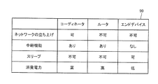
- FIG. 3 is a comparison diagram that summarizes the functions of the coordinator, router, and end device.
- the coordinator that is, control device 100 in FIG. 2 has a network startup function as described above, but the router and the end device do not have a network startup function. Further, the coordinator and the router have a relay function, but the end device does not have the relay function.
- the coordinator and router cannot sleep, but the end device can sleep.
- the reason why the end device can sleep is that it does not always need to be received. Therefore, generally speaking, the power consumption of the coordinator and the router is high.
- the power consumption of the end device is low.
- the actual measurement value of power consumption when a certain power consumption measuring device is operated as a router is about 0.4 W
- the actual measurement value of power consumption when operated as an end device is about 0.1 W. Met.
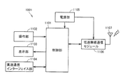
- FIG. 4 is a block diagram of the gateway 1001.
- the gateway 1001 includes a control unit 1101, an operation unit 1102, a display unit 1103, a high-speed communication interface unit 1104, a power supply unit 1105, a low-speed wireless communication module 1106, and an antenna 1107.
- the operation unit 1102 is an input device such as a switch.
- the display unit 1103 is an output device such as an LED (Light Emitting Diode).
- the high-speed communication interface unit 1104 is an interface for performing communication with the broadband router 1002 using Ethernet (registered trademark) or the like.
- the power supply unit 1105 supplies power to the control unit 1101 and the low-speed wireless communication module 1106.
- the control unit 1101 is connected to the operation unit 1102, the display unit 1103, the high-speed communication interface unit 1104, the power supply unit 1105, and the low-speed wireless communication module 1106.
- the control unit 1101 controls the overall operation of the gateway 1001.
- the control unit 1101 receives an input from the operation unit 1102. In addition, the control unit 1101 issues an output instruction to the display unit 1103.
- control unit 1101 includes a CPU (Central Processing Unit), a RAM (Random Access Memory), a ROM (Read Only Memory), a UART (Universal Asynchronous Receiver Transmitter), and a GPIO (General Purpose Input / Output). It consists of.
- the RAM, ROM, UART, and GPIO are each connected to the CPU.
- the low-speed wireless communication module 1106 is connected to the antenna 1107.
- the low-speed wireless communication module 1106 controls communication with communication devices existing on the low-speed wireless communication network Z. More specifically, the low-speed wireless communication module 1106 includes a CPU, a RAM, a ROM, a UART, a GPIO, and a wireless RF (Radio Frequency) unit.
- the RAM, ROM, UART, and GPIO are each connected to the CPU.
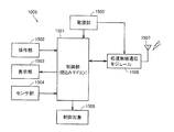
- FIG. 5 is a block diagram of an air conditioner 1005 (see FIG. 1). Note that other home appliances 1006 and 1007 also have similar blocks, and thus description thereof will not be repeated here.
- an air conditioner 1005 includes a control unit 1501, an operation unit 1502, a display unit 1503, a sensor unit 1504, a power supply unit 1505, a low-speed wireless communication module 1506, an antenna 1507, and a control target 1508.
- a control unit 1501 an operation unit 1502
- a display unit 1503 a sensor unit 1504
- a power supply unit 1505 a low-speed wireless communication module 1506, an antenna 1507, and a control target 1508.
- the operation unit 1502 is an input device such as a switch.
- the display unit 1503 is an output device such as an LED.
- the sensor unit 1504 is, for example, a temperature sensor or a humidity sensor.
- the power supply unit 1505 supplies power to the control unit 1501 and the low-speed wireless communication module 1506.
- the control unit 1501 is connected to the operation unit 1502, the display unit 1503, the sensor unit 1504, the power supply unit 1505, and the low-speed wireless communication module 1506.
- a control unit 1501 controls the overall operation of the air conditioner 1005.
- the control unit 1501 is generally realized by an embedded microcomputer.
- the control unit 1501 receives an input from the operation unit 1502. In addition, the control unit 1501 issues an output instruction to the display unit 1503. In addition, the control unit 1501 receives an input from the sensor unit 1504. The control unit 1501 controls a control target 1508 such as a compressor.
- control unit 1501 includes a CPU, a RAM, a ROM, a UART, a GPIO, and an ADC (Analog Digital Converter).
- the RAM, ROM, UART, and GPIO are each connected to the CPU.
- the ADC is connected to the sensor unit 1504.
- the low-speed wireless communication module 1506 is connected to the antenna 1507.
- the low-speed wireless communication module 1506 controls communication with the gateway 1001 and communication devices existing on the network Z.
- the low speed wireless communication module 1506 includes a CPU, a RAM, a ROM, a UART, a GPIO, and a wireless RF unit.
- the RAM, ROM, UART, and GPIO are each connected to the CPU.
- FIG. 6 is a diagram showing an appearance of the power consumption measuring device 1004.
- FIG. 6A is a perspective view of the power consumption measuring device 1004.
- FIG. 6B is a side view of the power consumption measuring device 1004.
- FIG.6 (c) is a perspective view of the power consumption measuring device 1004 when it sees from a different direction from Fig.6 (a).
- the power consumption measuring device 1004 includes a plug insertion socket 2101 on the surface 1004A of the power consumption measuring device 1004. 6B and 6C, a plug 2102 is provided on the surface 1004C of the power consumption measuring device 1004. Note that the surface 1004C is a surface opposite to the surface 1004A and is adjacent to the surface 1004B. A plug (outlet) of an electronic device such as a home appliance is inserted into the socket 2101.
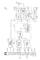
- FIG. 7 is a diagram illustrating a hardware configuration of the power consumption measuring device 1004.
- a power consumption measuring device 1004 includes a socket 2101, a plug 2102, a shunt resistor 2103, a power supply unit 2104, an LED 2105, a setting button 2106, an antenna 2107, a power sensor unit 2110, A low-speed wireless communication module 2120, a wiring 2131, a wiring 2132, and a wiring 2133 are provided.
- the power sensor unit 2110 includes a voltage input ADC unit 2111, a current input ADC unit 2112, a multiplier 2113, and a digital / frequency conversion unit 2114.
- the low-speed wireless communication module 2120 includes a CPU 2121, a ROM 2122, a RAM 2123, a GPIO 2124, and a wireless RF unit 2125.
- the wiring 2132 and the wiring 2133 are connected by a shunt resistor 2103.
- the shunt resistor 2103 is a very small (several hundred micro ohms) resistor used for measuring current.
- the socket 2101 and the plug 2102 are connected by wirings 2131 to 2133 and a shunt resistor 2103.
- the wiring 2131 is connected to one terminal of the plug 2102 and one terminal of the socket 2101.
- the wiring 2132 is connected to the other terminal of the plug 2102 and one end of the shunt resistor 2103.
- the wiring 2133 is connected to the other terminal of the socket 2101 and the other end of the shunt resistor 2103.
- the power supply unit 2104 is connected to the wiring 2132.
- the power supply unit 2104 converts alternating current into direct current.
- the power supply unit 2104 gives the DC power obtained by the conversion to the power sensor unit 2110 and the low-speed wireless communication module 2120.
- the voltage input ADC unit 2111 is connected to the wiring 2131 and the wiring 2132.
- the voltage input ADC unit 2111 outputs the voltage (potential difference) between the wiring 2131 and the wiring 2132 to the multiplier 2113 as a digital signal.
- the current input ADC unit 2112 is connected to the wiring 2132 and the wiring 2133.
- the current input ADC unit 2112 outputs the current value of the current flowing through the shunt resistor 2103 to the multiplier 2113 as a digital signal.
- the multiplier 2113 multiplies the output from the voltage input ADC unit 2111 and the output from the current input ADC unit 2112, and outputs a digital signal obtained by the multiplication to the digital / frequency conversion unit 2114.
- the digital / frequency converter 2114 converts the input digital signal into a frequency signal.
- the digital / frequency conversion unit 2114 outputs the frequency signal obtained by the conversion to the GPIO of the low-speed wireless communication module 2120.
- the CPU 2121 performs data conversion on the frequency signal acquired from GPIO.
- the wireless RF unit 2125 transmits a signal obtained by data conversion to the gateway 1001 using the antenna 2107.
- the ROM 2122 stores programs executed by the CPU 2121.
- the RAM 2123 temporarily stores data processed by the CPU 2121 and processed data.
- the LED 2105 represents the data processing state of the power consumption measuring device 1004 by a blinking color and / or a lighting color.
- the setting button 2106 is used for initial setting of the power consumption measuring device 1004 by the user.
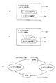
- FIG. 8 is a diagram showing a display example of the display screen of the personal computer 1003 and processing executed by selecting an input button displayed on the display screen.
- FIG. 8A and FIG. 8B are diagrams showing screens on the browser (HTTP client) of the personal computer 1003.
- the connection destination of the browser (HTTP client) is the HTTP server of the gateway 1001.
- FIG. 8C is a state transition diagram showing the state of the gateway 1001.
- the state of the gateway 1001 the input button 201 for instructing start of network construction, and the completion of network construction
- An input button 202 for instructing is displayed.
- the HTTP server of the gateway 1001 calls a small program called CGI (Common Gateway Interface) to check the state of the gateway 1001.
- CGI Common Gateway Interface
- the input button 201 is validated (selectable) and the input button 202 is invalidated (cannot be selected). If the state of the gateway 1001 is “under network construction”, the input button 201 is invalidated (cannot be selected), and the input button 202 is validated (can be selected). When the input button 201 and the input button 202 are pressed, the input signal is notified from the browser (HTTP client) of the personal computer 1003 to the HTTP server of the gateway 1001.
- the gateway 1001 has two states, “in operation of network” and “under construction of network”.
- the initial state is “in network operation”.
- the HTTP server of the gateway 1001 calls CGI, executes process A described later, and shifts to “network construction”.
- the HTTP server of the gateway 1001 calls CGI, executes process B described later, and shifts to “Network operation in progress”.
- the input buttons 201 and 202 are buttons displayed on the browser (HTTP client).
- the input means and display means of the gateway 1001 may be used.
- FIG. 9 is a diagram for explaining a state of each communication device before an input button 201 for instructing start of network construction is selected by the user. That is, FIG. 9 is a diagram “during network operation”.
- network Z there is a control device 100 that functions as a coordinator, a router, and an end device. Communication devices existing on the network Z, including the control device 100, are in the participation prohibition mode. That is, a communication device existing on the network Z is in a state where it cannot participate even if a new communication device 31 is attempted to participate. The control device 100 and the router are all in the “participation prohibited” state.
- the control device 100 transmits the following command to the communication devices 11 to 23 (node) configuring the network Z.
- a command hereinafter also referred to as a “router operation command” for causing a device that is an end device among the communication devices 11 to 23 to operate as a router;
- a command hereinafter referred to as “participation permission command” for causing each of the communication devices 11 to 23 to operate in an operation mode permitting participation of another new communication device (hereinafter also referred to as “participation permission mode”). Also called) Send.
- control device 100 transmits a “router operation command” in (i) and receives a signal indicating that the target communication device operates as a router, and then (ii) the communication devices 11 to 23.
- a “participation permission instruction” is transmitted.
- (I) and (ii) are transmitted in this order.
- the control device 100 (node) itself sets the participation permission mode.
- the control device 100 does not need to transmit a participation permission command again.
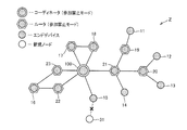
- FIG. 10 is a diagram showing a state of the network Z after transition from the state shown in FIG. Specifically, FIG. 10 is a diagram for explaining the state of each communication device after the input button 201 is selected. FIG. 10 is a diagram “under construction of network”.
- communication devices 11 to 23 when communication devices 11 to 23 receive a router operation command and a participation permission command, communication devices 11 to 23 operate as a router and shift to a participation permission mode. Also, the control device 100 itself shifts to the participation permission mode.
- the new communication device 31 can participate in the network with any one of them as a parent.
- the new communication device 31 can participate in the nearest communication device 15 as an example in the state of FIG. That is, the communication device 31 can have the communication device 15 as a parent.
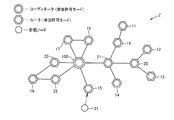
- FIG. 11 is a diagram illustrating the state of the network Z after transition from the state illustrated in FIG. Specifically, FIG. 11 is a diagram illustrating a state after the new communication device 31 has joined the network Z. Further, FIG. 11 is a diagram “during network construction”.
- the new communication device 31 participates in the nearest communication device 15. That is, the communication device 15 becomes the parent of the communication device 31. If there are new communication devices other than the communication device 31, the process is repeated until each new communication device joins the network Z.
- the gateway 1001 may display “new communication device has joined” on the display unit.
- a display indicating that “a new communication device has joined” may be displayed on the browser (HTTP client) of the personal computer 1003.
- the control device 100 determines “communication device RT” and “communication device ED” from the plurality of communication devices 11 to 23.
- the “communication device RT” is a communication device that must operate as a relay node (that is, a router).
- the “communication device ED” is a communication device that may be operated as a node without a relay function (that is, an end device).
- the “communication device RT” necessary to maintain the data relay function of the network is determined.
- the meaning of “maintaining the data relay function of the network” means that at least one communication path can be secured between the control device 100 and the plurality of communication devices 11 to 23.
- the control device 100 determines “communication device RT” and “communication device ED” according to a method described later.
- the communication devices 15 to 23 are determined to be communication devices RT that need to function as relay nodes, and the communication devices 11 to 14 and the communication device 31 are determined to be communication devices ED.
- the control device 100 transmits a command for operating the communication devices 11 to 14 as end devices to the communication devices 11 to 14 and the communication device 31 determined as the communication device ED. .
- the communication devices 11 to 14 and the communication device 31 operate as end devices based on the reception of the command.
- control device 100 transmits a participation prohibition command to the communication devices 15 to 23 determined to be the communication device RT.
- the communication devices 15 to 23 switch the operation mode of the own device from the participation permission mode to the participation prohibition mode.
- the control device 100 itself shifts to the participation prohibition mode.
- FIG. 12 is a diagram showing a state of the network Z after transition from the state shown in FIG. Specifically, FIG. 12 is a diagram illustrating a state after the input button 202 is selected and some communication devices are switched from the router to the end device. FIG. 12 is a diagram “in operation of the network”.
- a router and an end device exist on the network Z. Specifically, the communication devices 15 to 23 become routers, and the communication devices 11 to 14 and the new communication device 31 become end devices. In addition, communication devices existing on the network Z are in the participation prohibition mode including the control device 100.
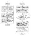
- FIG. 13 is a flowchart showing a data processing flow in the gateway 1001 corresponding to the control device 100.
- FIG. 13A is a flowchart for explaining the flow of processing (processing A) when the input button 201 is pressed.
- FIG. 13B is a flowchart for explaining the flow of processing (processing B) when the input button 202 is pressed.
- step S204 the gateway 1001 transmits a command for operating the communication device as a router to the communication device operating as an end device on the network Z.
- step S206 the gateway 1001 transmits a command to instruct the change to the participation permission mode to the communication device operating as a router on the network Z.
- step S208 the gateway 1001 changes the operation mode of the coordinator unit of the gateway 1001 itself from the participation prohibition mode to the participation permission mode. As a result, the operation mode of the communication device operating as a router or coordinator existing on the network Z becomes the participation permission mode. There is no participation permission / prohibition mode for end devices.
- the gateway 1001 determines the communication device RT and the communication device ED. More specifically, the gateway 1001 is a first communication device (hereinafter referred to as a relay node) that needs to function as a relay node in order to secure at least one communication path between the communication device and the gateway 1001 in each communication device. , Also referred to as communication device RT). Further, a second communication device other than the communication device RT (hereinafter also referred to as communication device ED) is determined.
- a relay node a first communication device that needs to function as a relay node in order to secure at least one communication path between the communication device and the gateway 1001 in each communication device.
- communication device RT Also referred to as communication device RT.
- a second communication device other than the communication device RT hereinafter also referred to as communication device ED is determined.
- step S216 the gateway 1001 transmits a command for operating as an end device to the communication device determined to be the communication device ED.
- step S218 the gateway 1001 determines whether all of the determined communication devices ED have been switched to end devices based on a signal from the communication device ED.
- step S220 all communication devices except for communication device ED operating as an end device. In other words, a command for instructing the change to the participation prohibition mode is transmitted to (all communication devices determined as the communication device RT). If gateway 1001 determines that all of the determined communication devices ED have not been switched to end devices (NO in step S218), the process proceeds to step S218.
- step S222 the gateway 1001 changes the operation mode of the coordinator unit of the gateway 1001 itself from the participation permission mode to the participation prohibition mode.
- ZigBee (registered trademark) standard commands are used for participation permission and prohibition. Specifically, a command “Mgmt_Permit_Joining_req” is used. If PermitDuration is “0”, it is prohibited. If PermitDuration is “255”, it is permitted. The command is disclosed in “2.4.3.3.7 Mgmt_Permit_Joining_req” of the specification “ZIGBEE SPECIFICATION” issued by ZigBee (registered trademark) Alliance.
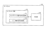
- FIG. 14 is a functional block diagram showing a functional configuration of the gateway 1001.
- gateway 1001 includes a determination unit 140 and a coordinator unit 150.
- the coordinator unit 150 includes an end device operation command transmission unit 151 and a router operation command transmission unit 152.
- the coordinator unit 150 is a functional block realized by the CPU in the low-speed wireless communication module 1106 in the gateway 1001 and various programs stored in the memory.
- the determination unit 140 determines a communication device RT that should operate as a relay node among the plurality of communication devices and a communication device ED other than the communication device RT. To do.
- the end device operation command transmission unit 151 transmits a command for operating the communication device as an end device to the communication device determined by the determination unit 140 as the communication device ED.
- the router operation command transmission unit 152 transmits a command for operating the communication device as a router to the communication device operating as an end device. To do.
- control device 100 corresponding to the gateway 1001 and the plurality of communication devices 11 to 23, 31 are described as devices that constitute the network Z.
- the description will be made assuming that the node is composed of nodes X0 to X13. It is assumed that the node X0 is the coordinator unit 150 of the gateway 1001.
- the communication device RT / communication device ED is determined by the following procedure.
- the determination unit 140 acquires a link quality index (LQI (Link Quality Index)) with a communication device recognized on the network Z from the coordinator unit 150 and each of the plurality of communication devices.
- the determination unit 140 determines the best communication path between the coordinator unit 150 and the communication device for each of a plurality of communication devices based on the acquired link quality index (LQI).
- the best communication route is a route that minimizes the total route cost. If there are a plurality of such communication paths, all communication paths are determined.
- the determination unit 140 creates a conditional expression based on the best route determined for each of the plurality of communication devices so that at least one best route is established.
- the conditional expression includes information for determining a communication device that must exist as a relay node. (4) The determination unit 140 solves the created conditional expression. As a result, a communication device that is indispensable as a relay node is determined as the communication device RT. The other communication device is determined as the communication device ED.
- the coordinator unit 150 uses a standard command of ZigBee (registered trademark).
- the commands are disclosed in “2.4.3.3.2 Mgmt_Lqi_req” and “2.4.4.3.2 Mgmt_Lqi_rsp” of the specification “ZIGBEE SPECIFICATION” issued by ZIGBEE (Registered Trademark) Alliance.
- the coordinator unit 150 acquires the LQI by using the command.
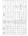
- FIG. 15 is a diagram for explaining a data table generated by the coordinator unit 150 as a result of the LQI inquiry. More specifically, FIG. 15 is a data table 1701 showing a plurality of LQIs.
- the LQI is indicated by any value from 0 to 255. That is, in FIG. 15, LQI is represented by 8 bits. The larger the LQI value, the better the link quality. A blank area in the data table 1701 indicates a state in which the counterpart device cannot be confirmed. How the LQI is calculated depends on the implementation of each communication device.
- RSSI Receiveive Signal Strength Indication
- LQI 0 means that RSSI is ⁇ 87 dBm or less.
- some implementations calculate by combining RSSI and a correlation value (correlation).
- the correlation value is a value calculated by the correlator in order to detect the start of frame reception in the physical layer. Combining RSSI and correlation will result in a more accurate link quality index (LQI). This is because RSSI alone cannot distinguish a significant signal from noise.
- the node X0 represents the coordinator unit 150 of the gateway 1001
- the nodes X1 to X12 represent twelve communication devices constituting the network Z.
- the LQI inquiry results for the node Xn are arranged in the row direction. For example, the LQI when viewing the node X1 from the node X0 is “12”, and the LQI when viewing the node X0 from the node X1 is “23”.
- the determination unit 140 converts the LQI into a route cost using a predetermined program. An example of the conversion will be described as follows.
- FIG. 16 is a diagram showing three correspondences between LQIs and route costs.
- FIG. 16A is a diagram showing the most preferable correspondence relationship among the three correspondence relationships.
- the determination unit 140 converts the LQI to the route cost according to the conversion table of FIG.
- the determination unit 140 assigns a route cost of “1” to “7” according to the LQI so that the route cost increases when the LQI is small.
- This route cost is a route cost for only one hop.
- AODV Ad-hoc On-Demand Distance Vectoring
- the determination unit 140 selects a communication path having the lowest total path cost (Path Cost).
- the determination unit 140 considers the communication path between the gateway 1001 and each communication device, the communication device RT that should function as a router, and the communication device ED that does not need to function as a router. Judgment processing to divide into
- the determination unit 140 obtains the best route using the following first reference and second reference.
- -First criterion the lowest total route cost-Second criterion: If the total route cost is the same, the number of hops is small. This is the method for finding the best route, but from the LQI table (per hop)
- the route cost is obtained, and the total route cost is calculated for every route that can reach the destination node from the source node. As a result, the route with the minimum total route cost is selected as the best route (first criterion). If the total route cost is the same, the route is selected as the best route with the few hops (second criterion).
- the first reference is prioritized, and if the result of the first reference is the same, the second reference is used.
- path quality index As an implementation, it is preferable to create a so-called “path quality index” by combining the first standard and the second standard.
- path quality index is as follows.
- Route quality index (total route cost) * 256 + number of hops ... Formula (Q) The route with the smallest route quality index is set as the best route.
- the route search is performed, either the breadth-first search or the depth-first search may be used, but the route must be pruned by any of the search methods. Otherwise, the route search will take an enormous amount of time.
- the pruning of the route is performed by stopping the search for the route ahead if the “route quality index” until the middle of the route exceeds the “route quality index” of the best route at that time.
- the determination unit 140 determines and stores all routes that are the same as the best route as a result of using the first reference and the second reference. When there are a plurality of best paths, it is considered that at least one of the best paths should be established.
- Nodes (communication devices) on the best route may be indispensable as relay nodes. However, whether or not it is really necessary as a relay node is determined by solving a conditional expression as described later.
- the node X2 becomes an indispensable relay node. That is, the communication device represented as the node X2 is a communication device RT that must operate as a router. Therefore, the conditional expression can be expressed by X2.
- node X2 or node X5 is an indispensable relay node. That is, either the node X2 or the node X5 is a communication device RT that must operate as a router. Therefore, the conditional expression can be expressed by X2
- the determination unit 140 obtains the best route between the node X0 and each of the nodes X1 to X12.
- the determination unit 140 obtains the best path for each communication device by using the node X0 as a transmission source node and all the communication devices (nodes X1 to 12) as transmission destination nodes. Further, in the reverse direction, the best route is obtained for each communication device with all communication devices (nodes X1 to X12) as the transmission source node and node X0 as the transmission destination node.
- the determination unit 140 obtains the best route for each communication device by solving the conditional expression. That is, the determination unit 140 determines an indispensable communication device as a relay node in order to maintain communication between the gateway 1001 and each communication device by solving the conditional expression.
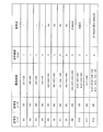
- FIG. 17 is a diagram illustrating a relationship among a transmission source node, a transmission destination node, a best route, a total route cost, and a conditional expression.
- a conditional expression is obtained.
- FIG. F (X2) && (X2
- Expression (1) is an overall conditional expression for simultaneously satisfying the respective conditional expressions.
- && is a logical AND operator
- is a logical OR operator.
- Xi i is a natural number of 1 to 12
- X2 is node X2.
- the nodes X2, X3, X4, X7, and X10 corresponding to X2, X3, X4, X7, and X10 must function as relay nodes.
- the determination unit 140 determines that the nodes X2, X3, X4, X7, and X10 are communication devices RT that operate as routers. Further, the determination unit 140 determines that the nodes X1, X5, X6, X8, X9, X11, and X12 other than the nodes X2, X3, X4, X7, and X10 among the nodes X1 to X12 are communication devices ED. That is, the determination unit 140 determines that the nodes (communication devices) may switch the nodes X1, X5, X6, X8, X9, X11, and X12 to end devices.
- FIG. 18 is a diagram showing the relationship between the best route, the total route cost, and the conditional expression when the transmission source node and the transmission destination node are exchanged.
- the best route from the node A to the node B and the best route from the node B to the node A in the opposite direction do not always follow the same route. This is because the transmission output power intensity and the reception sensitivity are different in each communication device.
- the conditional expressions for going and returning are different, but each must be considered.
- the nodes corresponding to X2, X3, X4, X7, and X10 are indispensable nodes as the routers in the conditional expression for going, and the nodes corresponding to X2, X4, X7, and X10 in the returning conditional expressions. It was determined.
- conditional expressions for going and returning may be combined with && to solve as a single conditional expression as a whole.
- the conversion table shown in FIG. 16A the conversion table shown in FIG. 16B or 16C may be used.
- the best route is different for different conversion tables. Accordingly, there is a possibility that the communication equipment that must exist as a repeater will also change.
- the number of nodes that are essential as a router will be slightly increased, but there is an advantage that the data relay function in the entire network becomes stronger. That is, the data relay function is maintained even if the communication state of the network changes slightly. Since maintaining the data relay function of the entire network must be prioritized above all, it is useful to “apply different translation tables simultaneously”.
- the coordinator unit 150 transmits a command for operating each device as an end device to each communication device determined to be the communication device ED.
- the coordinator unit 150 confirms that communication with each communication device is possible again after switching the communication device to an end device.
- the method of switching from the router to the end device is a non-standard method in ZigBee (registered trademark).
- the gateway 1001 transmits a command for instructing each node determined as the communication device ED to rewrite the NVRAM (Non Volatile RAM) parameter and reset the software.
- NVRAM Non Volatile RAM
- Each node that receives the command starts up as an end device by rewriting the NVRAM parameters and resetting the software. Specifically, each node that receives the command writes “2” in the logical type field (ZCD_NV_LOGICAL_TYPE) of the NVRAM parameters. “2” means an end device. After that, when the software is reset, it starts as an end device. Incidentally, if “1” is written in the logical type field, it becomes a router.
- Each node clears the network information and restarts as an end device, so it performs processing for joining the network again.
- the gateway 1001 confirms that communication can be performed between the gateway 1001 and the node after each node is switched to the end device.
- the gateway 1001 determines, for a plurality of communication devices, a communication device RT that needs to function as a relay node in order to secure at least one communication path between the communication device and the gateway 1001. The configuration of was explained.
- each communication device has two or more communication paths between the communication device and the gateway 1001 as much as possible. That is, the determination unit 140 may ensure that two or more good communication paths can be ensured (when the number of hops of the best path is two or more) in the communication paths between each communication device and the gateway 1001.
- the determination unit 140 determines that the nodes X2, X3, X4, X7, and X10 are communication devices RT that operate as routers. On the assumption of these, two or more good communication paths are secured. Find out if it is done. If two or more good communication paths cannot be secured, some nodes are additionally determined as communication devices RT. This technique can be implemented by adding a conditional expression as described above.
- the determination unit 140 can determine the communication device RT that should operate as a router and the communication device ED that can operate as an end device by solving the conditional expression to which such a restriction is added.
- the gateway 1001 manages the network Z including a plurality of communication devices that can operate as routers or end devices.
- the gateway 1001 determines, based on a predetermined input (depressing the input button 202), a communication device RT that should operate as a relay node among a plurality of communication devices and a communication device ED other than the communication device RT.
- Part 140 is provided.
- the gateway 1001 further includes an end device operation command transmission unit 151 that transmits a command for operating the communication device as an end device to the communication device determined by the determination unit 140 as the communication device ED.
- the gateway 1001 transmits a command for operating as an end device to a communication device determined as a communication device ED other than the communication device RT that should operate as a relay node among a plurality of communication devices. Therefore, the gateway 1001 can operate the communication devices ED in the plurality of communication devices constituting the network Z as end devices. That is, the gateway 1001 can operate a communication device that does not need to operate as a router as an end device. Therefore, the gateway 1001 can reduce power consumption in the network Z while maintaining the relay function in the network Z.
- the gateway 1001 transmits a command for operating the communication device as a router to the communication device ED operating as an end device based on a predetermined input (depressing the input button 201).
- the router operation command transmission unit 152 is further provided. Therefore, the user can operate the communication device operating as an end device as a router by performing the predetermined input.
- the communication device that is required to operate as a relay node for the determination unit 140 to secure at least one communication path between the communication device and the gateway 1001 for each of the plurality of communication devices. Is determined as a communication device RT. As a result, at least one communication path can be secured between each communication device and the gateway.
- the determination unit 140 determines, for each of the plurality of communication devices, the communication route in both directions of the communication route from the communication device to the gateway 1001 and the communication route from the gateway 1001 to the communication device.
- a communication device that is indispensable to operate as a relay node in order to secure at least one is determined as a communication device RT. As a result, at least one communication path can be secured in both directions between each communication device and the gateway.
- the determination unit 140 calculates, for each of the plurality of communication devices, the best communication route among the communication routes between the communication device and the gateway 1001.
- the determination unit 140 determines at least one communication device among the communication devices located on the best communication path as the communication device RT. Therefore, the gateway 1001 can determine a communication device that is preferably operated as a router from the viewpoint of communication quality.
- the determination unit 140 acquires a link quality index between each of the plurality of communication devices and the communication device other than the communication device existing on the network Z. Based on the acquired link quality index, the determination unit 140 calculates, for each of the plurality of communication devices, the best communication route among the communication routes between the communication device and the gateway 1001. The determination unit 140 determines at least one communication device among the communication devices located on the best communication path as the communication device RT. Therefore, the gateway 1001 can determine a communication device that is preferably operated as a router from the viewpoint of link quality.
- the determination unit 140 Based on the link quality index, the determination unit 140 sets the communication path that minimizes the total path cost as the best communication path. Therefore, the gateway 1001 can calculate the best communication path based on the link quality index.
- the determination unit 140 determines that the communication path with the smallest number of hops among the plurality of communication paths is the best communication path when there are a plurality of communication paths with the minimum total route cost. To do. Therefore, the gateway 1001 can calculate one best communication path even when there are a plurality of communication paths having the minimum total route cost.
- the communication device can operate as a router or an end device.
- the communication device starts an operation as an end device when receiving a command for operating as an end device from the gateway 1001, and starts operating as a router when receiving a command for operating as a router 1001. Therefore, the communication device can operate as an end device or a router based on a command from the gateway 1001.
- the communication device is a power consumption measuring device incorporating a power sensor and a communication module. Therefore, the gateway 1001 can acquire the power consumption measured by the power consumption meter.
- FIG. 19 is a diagram illustrating a schematic configuration of a network when a tablet terminal is used as a control device for the network Z. Specifically, FIG. 19 is a diagram illustrating a configuration of a network Z using a tablet terminal instead of the gateway 1001 and the personal computer 1003.
- network Z includes a tablet terminal 1009, a broadband router 1002, one or more power consumption measuring devices including power consumption measuring device 1004, and a plurality of home appliances (air conditioner 1005, refrigerator 1006, laundry A dryer 1007) and various sensors 1008.
- the tablet terminal 1009, one or more power consumption measuring devices, a plurality of home appliances 1005 to 1007, and various sensors 1008 constitute a low-speed wireless communication network Z.
- the tablet terminal 1009 is connected to the broadband router 1002 by high-speed wireless communication such as WiFi (registered trademark).
- WiFi registered trademark
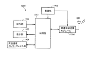
- FIG. 20 is a block diagram of the tablet terminal 1009.
- the tablet terminal 1009 includes a control unit 1901, an operation unit 1902, a display unit 1903, a high-speed communication interface unit 1904, a power supply unit 1905, a low-speed wireless communication module 1906, and an antenna 1907.
- the operation unit 1902 is an input device such as an operation key or a touch sensor.
- the display unit 1903 is an output device such as a liquid crystal display.
- the high-speed communication interface unit 1904 is an interface for performing wireless communication with the broadband router 1002.
- the power supply unit 1905 supplies power to the control unit 1901 and the low-speed wireless communication module 1906.
- the control unit 1901 is connected to the operation unit 1902, the display unit 1903, the high-speed communication interface unit 1904, the power supply unit 1905, and the low-speed wireless communication module 1906.
- a control unit 1901 controls the overall operation of the tablet terminal 1009.
- the control unit 1901 receives an input from the operation unit 1902.
- the control unit 1901 issues an output instruction to the display unit 1903.
- control unit 1901 includes a CPU, a RAM, a ROM, a UART, and a GPIO.
- the RAM, ROM, UART, and GPIO are each connected to the CPU.
- the low-speed wireless communication module 1906 is connected to the antenna 1107.
- the low-speed wireless communication module 1906 controls communication with the power consumption measuring device in the low-speed wireless communication network Z.
- the low-speed wireless communication module 1906 includes a CPU, RAM, ROM, UART, GPIO, and a wireless RF (Radio Frequency) unit.
- the RAM, ROM, UART, and GPIO are each connected to the CPU.
- the tablet terminal 1009 Since the tablet terminal 1009 has the above-described configuration, the same effect as that of the configuration using the gateway 1001 and the personal computer 1003 can be obtained.
- the gateway 1001 or the tablet terminal 1009 first checks whether or not “switching of router / end device” is possible for each home appliance. This is also true for ZigBee (registered trademark) nodes including all power consumption measuring devices. The gateway 1001 or the tablet terminal 1009 checks whether the ZigBee node can switch between the router and the end device. Note that the command for checking whether switching is possible can be realized by combining ZigBee (registered trademark) standard commands. Specifically, it is checked whether or not the corresponding cluster ID (Identification) is possessed. Having a corresponding cluster ID means whether a certain function is supported.
- the gateway 1001 or the tablet terminal 1009 checks valid endpoints for each communication device using a command “Active_EP_req” that is a standard command of ZigBee (registered trademark).
- the gateway 1001 or the tablet terminal 1009 acquires simple descriptor information for each valid endpoint using a command “Simple_Desc_req” that is a standard command of ZigBee (registered trademark).
- the simple descriptor information includes a list of cluster IDs supported by this endpoint. For this reason, the gateway 1001 or the tablet terminal 1009 checks whether or not there is a corresponding cluster ID.
- the gateway 1001 or the tablet terminal 1009 has the corresponding cluster ID, it can be understood that the gateway 1001 or the tablet terminal 1009 supports the function (router / end device switchable function).
- the gateway 1001 or the tablet terminal 1009 uses these standard commands to inquire whether “router / end device switching” is possible.
- route / end device switching is performed by writing the logical type of NVRAM parameter and applying software reset.
- a communication device attached to lighting since it is assumed in advance that a communication device attached to lighting is installed on the ceiling, such a communication device may be referred to as a “communication device RT”. This is because if it is installed on the ceiling, it can be expected to function well as a relay node. This is to determine whether or not to illuminate by looking at the device ID of the communication device.
- Simple descriptor information is acquired with a command “Simple_Desc_req” which is a standard command of ZigBee (registered trademark).
- Simple descriptor information includes Application device identifier (device ID).
- Application device identifier indicates the device ID of the communication device. If the Application device identifier is a Lighting Device described in, for example, Zigbee (registered trademark) Home Automation Profile, it can be determined that the device is a communication device attached to lighting.
- user descriptor information that is a standard function of ZigBee (registered trademark) can be used. Write the user descriptor information using the “2.4.3.1.12 User_Desc_set” command. Read the user descriptor information using the “2.4.3.1.9 User_Desc_req” command.
Landscapes
- Engineering & Computer Science (AREA)
- Computer Networks & Wireless Communication (AREA)
- Signal Processing (AREA)
- Mobile Radio Communication Systems (AREA)
Abstract
ネットワークの中継機能を維持しつつも、ネットワークにおける消費電力を低減可能な、ネットワークの制御装置を得る。制御装置は、ルータまたはエンドデバイスとして動作可能な通信機器を複数備えたネットワークを管理する。制御装置は、予め定められた入力に基づいて、複数の通信機器のうち中継ノードとして動作すべき第1の通信機器と、前記第1の通信機器以外の第2の通信機器とを判定する判定部と、判定部によって第2の通信機器と判定された通信機器に対して、当該通信機器をエンドデバイスとして動作させるための指令を送信するエンドデバイス動作指令送信部とを備える。
Description
本発明は、制御装置、通信機器、ネットワークシステム、ネットワーク管理方法、およびプログラムに関し、特に、パーソナルエリアネットワークを管理する制御装置、当該制御装置と通信を行なう通信機器、当該制御装置を備えるネットワークシステム、制御装置によるネットワーク管理方法、および制御装置を制御するプログラムに関する。
従来、パーソナルネットワークとして、たとえば、ZigBee(登録商標)を用いたネットワークが知られている。
非特許文献1および非特許文献2には、ZigBee(登録商標)の機能の一つとして、ルーティング機能が開示されている。特に、非特許文献1には、ルーティング機能の1つであるメッシュルーティングが開示されている。また、非特許文献2には、ZigBee(登録商標)で用いる、クラスタツリー構造を利用したクラスタツリールーティングと、メッシュ構造でP2P(Peer to Peer)通信を行なうテーブルルーティングとが開示されている。さらに、非特許文献2には、テーブルルーティングがIETF(Internet Engineering Task Force)のMANET(Mobile Ad-hoc On Demand Distance Vector Routing)のアルゴリズムに従って動作することも開示されている。
非特許文献3には、ZigBee(登録商標)の仕様が開示されている。特許文献3には、たとえば、ZigBee(登録商標)で用いられるコマンド等が開示されている。
特許文献1(特開2007-104174号公報)には、自身の構成要素の一部のみが動作するスリープモードを持つ省電力端末が開示されている。省電力端末は、(i)スリープモードにおいては、周期的に受信電波の検波処理を行い、この検波処理で所定の電波強度で所定時間長のウェークアップ信号を検出する無線回路部と、(ii)上記無線回路部が上記ウェークアップ信号を検出したことで上記一部以外の構成要素を起動してスリープモードからデータ通信ができるアクティブモードになるよう動作指示するマイクロコンピュータとを備えている。
また、従来、電力センサと通信モジュールとを内蔵した消費電力測定器が知られている。
Drew Gislason著「ZIGBEE WIRELESS NETWORKING」(米国)、Newnes、2008年9月4日、p.307-314,318,319,340-344
福永 茂「パーソナルエリアネットワークを実現する技術 -ZigBee- ZigBee-Wireless PAN Technology-」電子情報通信学会、通信ソサイエティマガジン No.2秋号 2007、2007年9月、解説論文、p.62-73
ZigBee Alliance「ZIGBEE SPECIFICATION ZigBee Document053474r17」、ZigBee Standards Organization、2008年1月17日
通信機能を有する制御装置が複数の通信機器との間で通信してデータを交換するという状況であって、制御装置はZigBee(登録商標)コーディネータ(以下、コーディネータとする)であるものとする。複数の通信機器をZigBee(登録商標)のノードとして用いる場合、当該通信機器は、ZigBee(登録商標)ルータ(以下、ルータとする)、および、ZigBee(登録商標)エンドデバイス(以下、エンドデバイスとする)のいずれかとして動作させることができるものとする。
通信機器をルータとして動作させる場合、当該通信機器はデータを中継することができる。しかし、当該通信機器をルータとして動作させると、常時受信可能な状態にしておく必要があるため、スリープに移行させることができない。(つまり、消費電力を低減できない)一方、通信機器をエンドデバイスとして動作させる場合、当該通信機器はスリープに移行させることができる。(つまり、消費電力を低減できる)しかし、当該通信機器をエンドデバイスとして動作させるとデータを中継できない。
このように、通信機器をルータとして動作させる場合であっても、あるいはエンドデバイスとして動作させる場合であっても、それぞれ、メリットおよびデメリットがある。
すべての通信機器をルータとして動作させると、データ中継機能が働くため、制御装置はそれぞれの通信機器との間で通信できやすくなるが、ネットワーク全体の消費電力は増えるであろう。
一方、すべての通信機器をエンドデバイスとして動作させると、ネットワーク全体の消費電力は下がるが、データ中継機能が働かないために、制御装置はいくつかの通信機器と通信できなくなるおそれが出てくるであろう。
本願発明は、上記問題点に鑑みなされたものであって、その目的は、ネットワークのデータ中継機能を維持しつつも、いくつかの通信機器をエンドデバイスに切り換えることによって、ネットワーク全体における消費電力を低減させるネットワークの制御装置、通信機器、ネットワークシステム、ネットワーク管理方法、およびプログラムを提供することにある。
本発明のある局面に従うと、制御装置は、ルータまたはエンドデバイスとして動作可能な通信機器を複数備えたネットワークを管理する。制御装置は、予め定められた入力に基づいて、複数の通信機器のうち中継ノードとして動作すべき第1の通信機器と、第1の通信機器以外の第2の通信機器とを判定する判定部と、判定部によって第2の通信機器と判定された通信機器に対して、当該通信機器をエンドデバイスとして動作させるための指令を送信するエンドデバイス動作指令送信部とを備える。
好ましくは、制御装置は、予め定められた入力に基づいて、エンドデバイスとして動作している前記第2の通信機器に対して、当該通信機器をルータとして動作させるための指令を送信するルータ動作指令送信部をさらに備える。
好ましくは、判定部は、複数の通信機器の各々に対して、当該通信機器と制御装置との間の通信経路を少なくとも1つ確保するために中継ノードとして動作することが必須である通信機器を第1の通信機器と判定する。
好ましくは、判定部は、複数の通信機器の各々に対して、当該通信機器から制御装置への方向の通信経路と、制御装置から当該通信機器への方向の通信経路の両方向において、通信経路を少なくとも1つ確保するために中継ノードとして動作することが必須である通信機器を第1の通信機器と判定する。
好ましくは、判定部は、複数の通信機器の各々に対して、当該通信機器と制御装置との間の通信経路のうちで最良となる通信経路を算出する。判定部は、最良となる通信経路上の間に位置する通信機器の中から少なくとも1以上の通信機器を第1の通信機器と判定する。
好ましくは、判定部は、複数の通信機器の各々から、当該通信機器とネットワーク上に存在する当該通信機器以外の通信機器との間のリンク品質指数を取得する。判定部は、取得したリンク品質指数に基づき、複数の通信機器の各々について、当該通信機器と制御装置との間の通信経路のうちで最良となる通信経路を算出する。判定部は、最良となる通信経路上の間に位置する通信機器の中から少なくとも1以上の通信機器を第1の通信機器と判定する。
好ましくは、判定部は、リンク品質指数に基づき、経路コストの合計が最小となる通信経路を最良の通信経路とする。
好ましくは、判定部は、リンク品質指数に基づき、経路コストの合計が最小となる通信経路が複数存在した場合、複数の通信経路のうちホップ数が最も少ない通信経路を最良の通信経路とする。
本発明の他の局面に従うと、通信機器は、ルータまたはエンドデバイスとして動作可能である。通信機器は、エンドデバイスとして動作させるための指令を受信するとエンドデバイスとしての動作を開始する。通信機器は、ルータとして動作させるための指令を受信するとルータとしての動作を開始する。
好ましくは、通信機器は、電力センサと通信モジュールとを内蔵した消費電力測定器である。
本発明のさらに他の局面に従うと、ネットワークシステムは、ルータまたはエンドデバイスとして動作可能な複数の通信機器と、当該複数の通信機器を含むネットワークを管理する制御装置とを備える。制御装置は、予め定められた入力に基づいて、複数の通信機器のうち中継ノードとして動作すべき第1の通信機器と、第1の通信機器以外の第2の通信機器とを判定する。制御装置は、第2の通信機器と判定された通信機器に対して、当該通信機器をエンドデバイスとして動作させるための指令を送信する。第2の通信機器は、指令を受信したことに基づき、エンドデバイとして動作する。
本発明のさらに他の局面に従うと、ネットワーク管理方法は、ルータまたはエンドデバイスとして動作可能な通信機器を複数備えたネットワークを管理する制御装置におけるネットワーク管理方法である。ネットワーク管理方法は、制御装置が、予め定められた入力に基づいて、複数の通信機器のうち中継ノードとして動作すべき第1の通信機器と、第1の通信機器以外の第2の通信機器とを判定するステップと、制御装置が、第2の通信機器と判定された通信機器に対して、当該通信機器をエンドデバイスとして動作させるための指令を送信するステップとを備える。
本発明のさらに他の局面に従うと、プログラムは、ルータまたはエンドデバイスとして動作可能な通信機器を複数備えたネットワークを管理する制御装置を制御するためのプログラムである。プログラムは、予め定められた入力に基づいて、複数の通信機器のうち中継ノードとして動作すべき第1の通信機器と、第1の通信機器以外の第2の通信機器とを判定するステップと、第2の通信機器と判定された通信機器に対して、当該通信機器をエンドデバイスとして動作させるための指令を送信するステップとを、制御装置に実行させる。
本発明によれば、ネットワークの中継機能を維持しつつも、ネットワーク全体における消費電力を低減可能となる。
以下、図面を参照しつつ、本発明の実施の形態に係るネットワークについて説明する。以下の説明では、同一の部品には同一の符号を付してある。それらの名称および機能も同じである。したがって、それらについての詳細な説明は繰り返さない。
<A.ネットワークの概要>
図1は、本発明の実施の形態に係るネットワークの概略構成を示した図である。図1を参照して、ネットワークZは、低速無線通信ネットワーク(主にZigBee(登録商標)を想定)を示す。ネットワークEは、高速通信ネットワーク(主に、Ethernet(登録商標)やWiFi(登録商標)を想定)を示す。ネットワークZは、HTTP(HyperText Transfer Protocol)サーバ機能を有するゲートウェイ1001と、ブロードバンドルータ1002と、パーソナルコンピュータ1003と、複数の消費電力測定器1004と、複数の家電機器(エアコン1005,冷蔵庫1006,洗濯乾燥機1007など)と、複数の各種センサ(温湿度センサや照度センサ、人感センサなど)1008とを備える。
図1は、本発明の実施の形態に係るネットワークの概略構成を示した図である。図1を参照して、ネットワークZは、低速無線通信ネットワーク(主にZigBee(登録商標)を想定)を示す。ネットワークEは、高速通信ネットワーク(主に、Ethernet(登録商標)やWiFi(登録商標)を想定)を示す。ネットワークZは、HTTP(HyperText Transfer Protocol)サーバ機能を有するゲートウェイ1001と、ブロードバンドルータ1002と、パーソナルコンピュータ1003と、複数の消費電力測定器1004と、複数の家電機器(エアコン1005,冷蔵庫1006,洗濯乾燥機1007など)と、複数の各種センサ(温湿度センサや照度センサ、人感センサなど)1008とを備える。
ゲートウェイ1001と、複数の消費電力測定器1004と、複数の家電機器1005,1006,1007と、複数の各種センサ1008とは、それぞれ、低速無線通信モジュールCM(以下、「無線モジュール」とも称する)を備える。図1では、低速無線通信モジュールCMのアンテナが外部アンテナのように図示されているが、アンテナはそれぞれの機器に内蔵されていてもよい。
また、ゲートウェイ1001と、複数の消費電力測定器1004と、複数の家電機器1005~1007と、各種センサ1008とにより、低速無線通信ネットワークZ(以下、単に「ネットワークZ」とも称する)を構成する。
ゲートウェイ1001は、Ethernet(登録商標)によりブロードバンドルータ1002に接続されている。ゲートウェイ1001は、複数の消費電力測定器1004との間で低速度の無線通信を行なう。図1に消費電力測定器1004は1つしか描かれていないが実際には複数台存在するものとする。また、ゲートウェイ1001は、家電機器1005~1007および各種センサ1008との間においても、低速度の無線通信を行なう。
ブロードバンドルータ1002は、インターネットに接続されていてもよい。パーソナルコンピュータ1003は、Ethernet(登録商標)やWiFi(登録商標)により、ブロードバンドルータ1002に接続される。
パーソナルコンピュータ1003は、ブラウザ(HTTPクライアント)が動作する一般的なパソコンである。パーソナルコンピュータ1003は、パーソナルコンピュータ1003のブラウザを経由してゲートウェイ1001のHTTPサーバと通信する。このようにして、パーソナルコンピュータ1003は、ゲートウェイ1001のさまざま設定を行なうことができる。このHTTPサーバとHTTPクライアントの働きによって、貧弱な入力装置しか持たないゲートウェイ1001でも、複雑な設定を行なうことができる。本実施例では、パーソナルコンピュータ1003をゲートウェイ1001の入力手段及び表示手段として使うだけである。もしゲートウェイ1001に充実した入力手段と表示手段が備わっていれば、ゲートウェイ1001の入力手段と表示手段を用いて実施することもできる。
以下では、詳細については後述するが、消費電力測定器1004をルータとエンドデバイスのいずれかとして動作させる(つまり、消費電力測定器の動作モードを切り換える)ことについて説明する。しかしながら、これに限定されず、家電機器1005,1006,1007および各種センサ1008についても、上記のようにルータとエンドデバイスとの間で切り換えるようにネットワークZを構成してもよい。
図2は、ネットワークZの通信経路を含んだ概略構成を示した図である。以下では、ネットワークZとして、家電向けの短距離無線通信規格の一つであるZigBee(登録商標)を用いた例について説明する。なお、ZigBee(登録商標)は、Blootooth(登録商標)よりも低速かつ伝送距離も短いが、省電力かつ低コストという利点がある。
図2を参照して、ネットワークZは、制御装置100と、制御装置100との間で通信を行なう複数の通信機器11~23とを備えている。なお、制御装置100は、コーディネータとして機能する。通信機器は、ルータまたはエンドデバイスのいずれかとして機能する。
なお、説明の都合上、図2の通信機器11~23はすべてルータとエンドデバイスの切換可能であるものとするが、ルータとエンドデバイスの切換可能ではない通信機器(図示しない)があってもよい。
図1のゲートウェイ1001は、制御装置100に相当する。図1の複数の消費電力測定器1004と、複数の家電機器1005,1006,1007と、複数の各種センサ1008のうち、ルータとエンドデバイス切換可能であるものは、通信機器11~23に相当する。なお、一般的に、バッテリ動作する通信機器は、ルータとエンドデバイス切換可能ではない。
以下では、ネットワークZの詳細な説明を行なう前に、まず、ZigBee(登録商標)で使用されるデバイスについて説明する。ZigBee(登録商標)で使用されるデバイスは、物理デバイスと論理デバイスとの観点から区分される。
物理デバイスの観点から、ZigBee(登録商標)で使用されるデバイスは、IEEE802.15.4の規格に応じて、フル機能を備えたFFD(Full-Function Device)と、一部の機能を省略したRFD(Reduced-Function Device)とに分類できる。FFDは、ルーティング機能が備わっている。このため、FFDは、データを中継することができる。一方、RFDは、ルーティング機能が備わっていない。このため、RFDは、データを中継することができない。
論理デバイスの観点から、ZigBee(登録商標)で使用されるデバイスは、コーディネータと、ルータと、エンドデバイスとに分類できる。コーディネータは、ネットワークに必ず1つだけ存在する。ルータは、ネットワーク内に複数存在することが可能である。ルータによって、データがノードを次々に渡っていくマルチホップネットワークを実現できる。
コーディネータおよびルータは、ルーティング機能が備わるFFDでなければならない。エンドデバイスは、FFDであってもRFDであってもよい。本実施の形態における通信機器11~23は、ルータとエンドデバイスの切換可能である通信機器であり、FFDでなければならない。
制御装置100は、後述する方法によって、通信機器11~23が、ルータとエンドデバイスの切替可能であるかどうかを判別できるものとする。なお、制御装置100と通信機器11~23は、あらかじめ同一ネットワークに参加しているものとする。
図3は、コーディネータと、ルータと、エンドデバイスとの機能をまとめた対比図である。図3を参照して、コーディネータ(つまり、図2の制御装置100)は、上述したようにネットワークの立ち上げ機能を有するが、ルータおよびエンドデバイスは、ネットワークの立ち上げ機能を有していない。また、コーディネータおよびルータは、中継機能を有するが、エンドデバイスは中継機能を有していない。
さらに、コーディネータおよびルータは、スリープ不可であるが、エンドデバイスは、スリープできる。エンドデバイスがスリープできる理由は、常に受信する必要がないためである。従って、一般的に言えばコーディネータとルータの消費電力は高くなる。エンドデバイスの消費電力は低くなる。なお、参考までに、ある消費電力測定器をルータとして動作させた場合の消費電力の実測値は約0.4Wであり、エンドデバイスとして動作させた場合の消費電力の実測値は約0.1Wであった。
<B.制御装置の構成>
まず、ゲートウェイ1001について説明する。次いで、パーソナルコンピュータ1003について説明する。
まず、ゲートウェイ1001について説明する。次いで、パーソナルコンピュータ1003について説明する。
図4は、ゲートウェイ1001のブロック図である。ゲートウェイ1001は、制御部1101と、操作部1102と、表示部1103と、高速通信インターフェイス部1104と、電源部1105と、低速無線通信モジュール1106と、アンテナ1107とを備える。
操作部1102は、スイッチ等の入力デバイスである。表示部1103は、LED(Light Emitting Diode)等の出力デバイスである。高速通信インターフェイス部1104は、ブロードバンドルータ1002との間でEthernet(登録商標)等を用いた通信を行なうためのインターフェイスである。電源部1105は、制御部1101と低速無線通信モジュール1106とに電力を供給する。
制御部1101は、操作部1102、表示部1103と、高速通信インターフェイス部1104と、電源部1105と、低速無線通信モジュール1106とに接続されている。制御部1101は、ゲートウェイ1001の全体的な動作を制御する。制御部1101は、操作部1102からの入力を受け付ける。また、制御部1101は、表示部1103に出力指示を出す。
より詳しくは、制御部1101は、CPU(Central Processing Unit)と、RAM(Random Access Memory)と、ROM(Read Only Memory)と、UART(Universal Asynchronous Receiver Transmitter)と、GPIO(General Purpose Input/Output)とで構成される。RAMと、ROMと、UARTと、GPIOとは、それぞれ、CPUに接続されている。
低速無線通信モジュール1106は、アンテナ1107と接続されている。低速無線通信モジュール1106は、低速無線通信ネットワークZ上に存在する通信機器との間の通信を制御する。より詳しくは、低速無線通信モジュール1106は、CPUと、RAMと、ROMと、UARTと、GPIOと、無線RF(Radio Frequency)部で構成される。RAMと、ROMと、UARTと、GPIOとは、それぞれ、CPUに接続されている。
<C.家電機器の構成>
図5は、エアコン1005(図1参照)のブロック図である。なお、他の家電機器1006,1007も類似のブロックを有するため、ここでは説明を繰り返さない。
図5は、エアコン1005(図1参照)のブロック図である。なお、他の家電機器1006,1007も類似のブロックを有するため、ここでは説明を繰り返さない。
図5を参照して、エアコン1005は、制御部1501と、操作部1502と、表示部1503と、センサ部1504と、電源部1505と、低速無線通信モジュール1506と、アンテナ1507と、制御対象1508とを備える。
操作部1502は、スイッチ等の入力デバイスである。表示部1503は、LED等の出力デバイスである。センサ部1504は、たとえば、温度センサ、湿度センサである。電源部1505は、制御部1501と低速無線通信モジュール1506とに電力を供給する。
制御部1501は、操作部1502、表示部1503と、センサ部1504と、電源部1505と、低速無線通信モジュール1506とに接続されている。制御部1501は、エアコン1005の全体的な動作を制御する。制御部1501は、一般的に組込みマイコンで実現される。
制御部1501は、操作部1502からの入力を受け付ける。また、制御部1501は、表示部1503に出力指示を出す。また、制御部1501は、センサ部1504による入力を受け付ける。制御部1501は、コンプレッサ等の制御対象1508を制御する。
より詳しくは、制御部1501は、CPUと、RAMと、ROMと、UARTと、GPIOと、ADC(Analog Digital Converter)とで構成される。RAMと、ROMと、UARTと、GPIOとは、それぞれ、CPUに接続されている。ADCは、センサ部1504に接続される。
低速無線通信モジュール1506は、アンテナ1507と接続されている。低速無線通信モジュール1506は、ネットワークZ上に存在するゲートウェイ1001や通信機器との間の通信を制御する。低速無線通信モジュール1506は、CPUと、RAMと、ROMと、UARTと、GPIOと、無線RF部で構成される。RAMと、ROMと、UARTと、GPIOとは、それぞれ、CPUに接続されている。
<D.消費電力測定器の構成>
図6は、消費電力測定器1004の外観を示した図である。図6(a)は、消費電力測定器1004の斜視図である。図6(b)は、消費電力測定器1004の側面図である。図6(c)は、図6(a)とは異なる方向から視た場合における消費電力測定器1004の斜視図である。
図6は、消費電力測定器1004の外観を示した図である。図6(a)は、消費電力測定器1004の斜視図である。図6(b)は、消費電力測定器1004の側面図である。図6(c)は、図6(a)とは異なる方向から視た場合における消費電力測定器1004の斜視図である。
図6(a)を参照して、消費電力測定器1004は、消費電力測定器1004の表面1004Aに、プラグ差込用のソケット2101を備える。図6(b)および図6(c)を参照して、消費電力測定器1004の表面1004Cに、プラグ2102を備える。なお、表面1004Cは、表面1004Aとは反対側の面であり、表面1004Bに隣接する面である。ソケット2101には、家電等の電子機器のプラグ(コンセント)が差し込まれる。
図7は、消費電力測定器1004のハードウェア構成を表した図である。図7を参照して、消費電力測定器1004は、ソケット2101と、プラグ2102と、シャント抵抗2103と、電源部2104と、LED2105と、設定ボタン2106と、アンテナ2107と、電力センサ部2110と、低速無線通信モジュール2120と、配線2131と、配線2132と、配線2133とを備える。
電力センサ部2110は、電圧入力ADC部2111と、電流入力ADC部2112と、乗算器2113と、デジタル/周波数変換部2114とを含む。低速無線通信モジュール2120は、CPU2121と、ROM2122と、RAM2123と、GPIO2124と、無線RF部2125とを含む。
配線2132と配線2133とは、シャント抵抗2103により接続されている。シャント抵抗2103は電流を測定するために使われる微小な(数百マイクロΩ)抵抗である。
ソケット2101とプラグ2102とは、配線2131~2133およびシャント抵抗2103で接続されている。配線2131は、プラグ2102の一方の端子およびソケット2101の一方の端子に接続されている。配線2132は、プラグ2102の他方の端子とシャント抵抗2103の一方の端部とに接続されている。配線2133は、ソケット2101の他方の端子とシャント抵抗2103の他方の端部とに接続されている。
電源部2104は、配線2132に接続されている。電源部2104は、交流を直流に変換する。電源部2104は、変換により得られた直流電力を電力センサ部2110と低速無線通信モジュール2120とに与える。
電圧入力ADC部2111は、配線2131と、配線2132とに接続されている。電圧入力ADC部2111は、配線2131と配線2132との間の電圧(電位差)を、デジタル信号にて乗算器2113に出力する。
電流入力ADC部2112は、配線2132と、配線2133とに接続されている。電流入力ADC部2112は、シャント抵抗2103に流れる電流の電流値を、デジタル信号にて乗算器2113に出力する。
乗算器2113は、電圧入力ADC部2111からの出力と、電流入力ADC部2112からの出力とを乗算し、当該乗算により得られたデジタル信号をデジタル/周波数変換部2114に出力する。
デジタル/周波数変換部2114は、入力されたデジタル信号を周波数信号に変換する。デジタル/周波数変換部2114は、変換により得られた周波数信号を、低速無線通信モジュール2120のGPIOに出力する。
CPU2121は、GPIOから取得した上記周波数信号をデータ変換する。無線RF部2125は、データ変換により得られた信号を、アンテナ2107を用いてゲートウェイ1001に送信する。
ROM2122には、CPU2121が実行するプログラム等が格納されている。RAM2123は、CPU2121が処理するデータおよび処理したデータを一時的に格納する。
LED2105は、消費電力測定器1004のデータ処理状態を、点滅および/または点灯させる色等により表す。設定ボタン2106は、ユーザによる消費電力測定器1004の初期設定等のために用いられる。
<E.ネットワークの動作概要>
次に、ネットワークZに含まれる各機器の動作概要について説明する。なお、以下で示す動作概要は、一例であって、これに限定されるものではない。
次に、ネットワークZに含まれる各機器の動作概要について説明する。なお、以下で示す動作概要は、一例であって、これに限定されるものではない。
図8は、パーソナルコンピュータ1003の表示画面の表示例と、当該表示画面に表示された入力ボタンの選択により実行される処理とを表した図である。図8(a)および図8(b)は、パーソナルコンピュータ1003のブラウザ(HTTPクライアント)上の画面を示した図である。ブラウザ(HTTPクライアント)の接続先はゲートウェイ1001のHTTPサーバである。図8(c)は、ゲートウェイ1001の状態を示す状態遷移図である。
図8(a)および図8(b)を参照して、ブラウザ(HTTPクライアント)の画面上に、ゲートウェイ1001の状態と、ネットワークの構築の開始を指示する入力ボタン201と、ネットワークの構築の完了を指示する入力ボタン202と、が表示される。
ゲートウェイ1001のHTTPサーバは、ブラウザ(HTTPクライアント)からアクセスがあると、CGI(Common Gateway Interface)と呼ばれる小さなプログラムを呼び出して、ゲートウェイ1001の状態を調べる。
ゲートウェイ1001の状態が「ネットワーク運用中」ならば、入力ボタン201を有効化(選択可能)し、入力ボタン202を無効化(選択不可)する。ゲートウェイ1001の状態が「ネットワーク構築中」ならば、入力ボタン201を無効化(選択不可)し、入力ボタン202を有効化(選択可能)する。入力ボタン201、入力ボタン202が押されると、パーソナルコンピュータ1003のブラウザ(HTTPクライアント)からゲートウェイ1001のHTTPサーバにその入力信号が通知される。
図8(c)を参照して、ゲートウェイ1001には2つの状態、「ネットワーク運用中」と「ネットワーク構築中」である。初期状態は「ネットワーク運用中」である。「ネットワーク運用中」に入力ボタン201が選択されると、ゲートウェイ1001のHTTPサーバはCGIを呼び出して後述する処理Aを実行し、「ネットワーク構築中」に移行する。「ネットワーク構築中」に入力ボタン202が選択されると、ゲートウェイ1001のHTTPサーバはCGIを呼び出して後述する処理Bを実行し、「ネットワーク運用中」に移行する。
入力ボタン201,202は、ブラウザ(HTTPクライアント)上に表示されるボタンである。あるいは、先に述べたように、ゲートウェイ1001に充実した入力手段と表示手段が備わっていれば、ゲートウェイ1001の入力手段と表示手段を用いてもよい。
図9は、ユーザによって、ネットワークの構築の開始を指示する入力ボタン201が選択される前の各通信機器の状態を説明するための図である。すなわち、図9は「ネットワーク運用中」の図である。図9を参照して、ネットワークZ上には、コーディネータとして機能する制御装置100と、ルータと、エンドデバイスとが存在する。ネットワークZ上に存在する通信機器は、制御装置100を含めて、参加禁止モードになっている。つまり、ネットワークZ上に存在する通信機器は、新たな通信機器31を参加させようとしても参加できない状態となっている。制御装置100とルータとは、すべて「参加禁止」状態となっている。
図9の状態において、入力ボタン201が選択されると、制御装置100(ノード)は、ネットワークZを構成している通信機器11~23(ノード)に対して、以下の指令を送信する。
(i)通信機器11~23のうちエンドデバイスである機器に対してルータとして動作させるための指令(以下、「ルータ動作指令」とも称する)と、
(ii)通信機器11~23の各々に対して他の新しい通信機器の参加を許可する動作モード(以下、「参加許可モード」とも称する)で動作させるための指令(以下、「参加許可指令」とも称する)と、
を送信する。
(i)通信機器11~23のうちエンドデバイスである機器に対してルータとして動作させるための指令(以下、「ルータ動作指令」とも称する)と、
(ii)通信機器11~23の各々に対して他の新しい通信機器の参加を許可する動作モード(以下、「参加許可モード」とも称する)で動作させるための指令(以下、「参加許可指令」とも称する)と、
を送信する。
より詳しくは、制御装置100は、(i)で「ルータ動作指令」を送信して、対象となる通信機器がルータとして動作したことを示す信号を受信した後に、(ii)通信機器11~23に対して「参加許可指令」を送信する。(i)、(ii)の順に送信する。また、制御装置100(ノード)自身も参加許可モードに設定する。
なお、通信機器が、ルータとして動作を開始した場合に、デフォルトで参加許可モードとなる場合には、制御装置100は改めて参加許可指令を送信する必要はない。
図10は、図9に示した状態から遷移した後のネットワークZの状態を示した図である。具体的には、図10は、入力ボタン201が選択された後の各通信機器の状態を説明するための図である。また、図10は「ネットワーク構築中」の図である。
図10を参照して、通信機器11~23がルータ動作指令と参加許可指令を受信すると、通信機器11~23は、ルータとして動作するとともに、参加許可モードに移行する。また、制御装置100自身も、参加許可モードに移行する。
新たな通信機器31は、各通信機器11~23および制御装置100が参加許可モードであるため、これらのうちいずれかを親としてネットワークに参加できるようになる。たとえば、新たな通信機器31は、図10の状態においては一例として最寄の通信機器15に参加することができるようになる。つまり、通信機器31が、通信機器15を親とすることができるようになる。
図11は、図10に示した状態から遷移した後のネットワークZの状態を示した図である。具体的には、図11は、新しい通信機器31がネットワークZに参加した後の状態を表した図である。また、図11は「ネットワーク構築中」の図である。
図11を参照して、新たな通信機器31は、最寄の通信機器15に参加する。つまり、通信機器15が、通信機器31の親となる。なお、通信機器31以外にも新たな通信機器がある場合には、新たな通信機器の各々がネットワークZに参加するまで処理を繰り返す。新たな通信機器がネットワークZに参加されると、ゲートウェイ1001はその表示部に「新しい通信機器が参加した」という意味の表示をしてもよい。また、パーソナルコンピュータ1003のブラウザ(HTTPクライアント)上に「新しい通信機器が参加した」という意味の表示をしてもよい。
ネットワークの構築の完了を指示する入力ボタン202が選択されると、制御装置100は、複数の通信機器11~23の中から「通信機器RT」と「通信機器ED」とを判定する。「通信機器RT」は、中継ノード(すなわちルータ)として動作しなければならない通信機器のことである。「通信機器ED」は、中継機能無しノード(すなわちエンドデバイス)として動作させてもよい通信機器のことである。
より詳しくは、ネットワークのデータ中継機能を維持するのに必要な「通信機器RT」を判定する。「ネットワークのデータ中継機能を維持する」という意味は、制御装置100と複数の通信機器11~23との間で通信経路を少なくとも1つ確保できるということである。
入力ボタン202が選択されると、制御装置100は、後述する方法に従って、「通信機器RT」と「通信機器ED」とを判定する。ここでは、通信機器15~23を中継ノードとして機能することが必要な通信機器RTと判定し、通信機器11~14および通信機器31を通信機器EDと判定したものとする。
入力ボタン202が選択されると、制御装置100は、通信機器EDとして判定した通信機器11~14および通信機器31に対して、通信機器11~14をエンドデバイスとして動作させるための指令を送信する。通信機器11~14および通信機器31は、当該指令を受信したことに基づき、エンドデバイスとして動作する。
さらに、制御装置100は、通信機器RTと判定した通信機器15~23に対して、参加禁止指令を送信する。通信機器15~23は、当該参加禁止指令を受信すると、自機器の動作モードを参加許可モードから参加禁止モードへ切り換える。また、制御装置100自身も参加禁止モードへ移行する。
図12は、図11に示した状態から遷移した後のネットワークZの状態を示した図である。具体的には、図12は、入力ボタン202が選択され、一部の通信機器がルータからエンドデバイスに切り換った後の状態を表した図である。また、図12は「ネットワーク運用中」の図である。
図12を参照して、ネットワークZ上には、コーディネータとして機能する制御装置100以外に、ルータと、エンドデバイスとが存在することになる。具体的には、通信機器15~23が、ルータとなり、通信機器11~14および新たな通信機器31がエンドデバイスとなる。また、ネットワークZ上に存在する通信機器は、制御装置100を含めて、参加禁止モードになる。
以上の処理により、新たな通信機器31を加えた新たなネットワークが構築された。再度、新しい通信機器を追加させたい場合は、図9~図12で示した処理を繰り返せばよい。
<F.制御構造>
図13は、制御装置100に相当するゲートウェイ1001おけるデータ処理の流れを示したフローチャートである。図13(a)は、入力ボタン201が押されたときの処理(処理A)の流れを説明するためのフローチャートである。図13(b)は、入力ボタン202が押されたときの処理(処理B)の流れを説明するためのフローチャートである。
図13は、制御装置100に相当するゲートウェイ1001おけるデータ処理の流れを示したフローチャートである。図13(a)は、入力ボタン201が押されたときの処理(処理A)の流れを説明するためのフローチャートである。図13(b)は、入力ボタン202が押されたときの処理(処理B)の流れを説明するためのフローチャートである。
図13(a)を参照して、入力ボタン201が選択されると、ゲートウェイ1001は、ステップS204以降を実施する。ステップS204において、ゲートウェイ1001は、ネットワークZ上に存在するエンドデバイスとして動作中の通信機器に対して、通信機器をルータとして動作させるための指令を送信する。
ステップS206において、ゲートウェイ1001は、ネットワークZ上に存在するルータとして動作中の通信機器に対して、参加許可モードへの変更を指示する指令を送信する。ステップS208において、ゲートウェイ1001は、ゲートウェイ1001自身のコーディネータ部の動作モードを、参加禁止モードから参加許可モードに変更する。これにより、ネットワークZ上に存在するルータまたはコーディネータとして動作中の通信機器の動作モードは参加許可モードとなる。なお、エンドデバイスには参加許可/禁止モードというのはない。
図13(b)を参照して、入力ボタン202が選択されると、ゲートウェイ1001は、ステップS214以降を実施する。ステップS214において、ゲートウェイ1001は、通信機器RTと通信機器EDを判定する。より詳細には、ゲートウェイ1001は、それぞれの通信機器において、当該通信機器とゲートウェイ1001との通信経路を少なくとも1つ確保するために、中継ノードとして機能することが必要な第1の通信機器(以下、通信機器RTとも称する)を判定する。また、通信機器RT以外の第2の通信機器(以下、通信機器EDとも称する)を判定する。
ステップS216において、ゲートウェイ1001は、通信機器EDと判定された通信機器に対して、エンドデバイスとして動作させるための指令を送信する。ステップS218において、ゲートウェイ1001は、判定された通信機器EDの全てがエンドデバイスに切り換ったか否かを、通信機器EDからの信号に基づき判断する。
ゲートウェイ1001は、判定された通信機器EDの全てがエンドデバイスに切り換ったと判断すると(ステップS218においてYES)、ステップS220において、エンドデバイスとして動作している通信機器EDを除いた全ての通信機器(つまり、通信機器RTとして判定された全ての通信機器)に対して、参加禁止モードへの変更を指示する指令を送信する。ゲートウェイ1001は、判定された通信機器EDの全てがエンドデバイスに切り換っていないと判断すると(ステップS218においてNO)、処理をステップS218に進める。
ステップS222において、ゲートウェイ1001は、ゲートウェイ1001自身のコーディネータ部の動作モードを参加許可モードから参加禁止モードに変更する。
参加許可と参加禁止に関しては、ZigBee(登録商標)の標準的なコマンドを使う。具体的には、「Mgmt_Permit_Joining_req」というコマンドを使う。PermitDurationが“0”ならば禁止であり、PermitDurationが“255”ならば許可である。当該コマンドに関しては、ZigBee(登録商標) Allianceが発行している仕様書「ZIGBEE SPECIFICATION」の「2.4.3.3.7 Mgmt_Permit_Joining_req」に開示されている。
<G.機能ブロック>
図14は、ゲートウェイ1001の機能的構成を示す機能ブロック図である。図14を参照して、ゲートウェイ1001は、判定部140と、コーディネータ部150とを備える。コーディネータ部150は、エンドデバイス動作指令送信部151と、ルータ動作指令送信部152とを備える。なお、コーディネータ部150は、ゲートウェイ1001における低速無線通信モジュール1106におけるCPUおよびメモリに格納された各種プログラム等により実現される機能ブロックである。
図14は、ゲートウェイ1001の機能的構成を示す機能ブロック図である。図14を参照して、ゲートウェイ1001は、判定部140と、コーディネータ部150とを備える。コーディネータ部150は、エンドデバイス動作指令送信部151と、ルータ動作指令送信部152とを備える。なお、コーディネータ部150は、ゲートウェイ1001における低速無線通信モジュール1106におけるCPUおよびメモリに格納された各種プログラム等により実現される機能ブロックである。
判定部140は、入力ボタン202(図13(b)参照)が押されると、前記複数の通信機器のうち中継ノードとして動作すべき通信機器RTと、通信機器RT以外の通信機器EDとを判定する。
エンドデバイス動作指令送信部151は、判定部140によって通信機器EDと判定された通信機器に対して、当該通信機器をエンドデバイスとして動作させるための指令を送信する。ルータ動作指令送信部152は、入力ボタン201(図13(a)参照)が押されると、エンドデバイスとして動作している通信機器に対して、当該通信機器をルータとして動作させるための指令を送信する。
<H.通信機器RT/通信機器EDの判定処理の詳細>
次に、通信機器RT/通信機器EDの判定処理の詳細について説明する。なお、上記においては、ゲートウェイ1001に相当する制御装置100および複数の通信機器11~23,31がネットワークZを構成する機器であるとして説明したが、以下では説明の便宜上、ネットワークZが13個のノードX0~X13で構成されているものとして説明する。なお、ノードX0は、ゲートウェイ1001のコーディネータ部150であるものとする。
次に、通信機器RT/通信機器EDの判定処理の詳細について説明する。なお、上記においては、ゲートウェイ1001に相当する制御装置100および複数の通信機器11~23,31がネットワークZを構成する機器であるとして説明したが、以下では説明の便宜上、ネットワークZが13個のノードX0~X13で構成されているものとして説明する。なお、ノードX0は、ゲートウェイ1001のコーディネータ部150であるものとする。
(h1.手順)
以下の手順で通信機器RT/通信機器EDを判定する。
(1)まず、判定部140は、コーディネータ部150と複数の通信機器の各々から、ネットワークZ上に認識される通信機器とのリンク品質指数(LQI(Link Quality Index))を取得する。
(2)判定部140は、取得したリンク品質指数(LQI)に基づき、複数の通信機器の各々について、コーディネータ部150と当該通信機器との間の最良の通信経路を決定する。最良の通信経路とは、経路コストの合計が最小となる経路のことである。そのような通信経路が複数存在する場合は、すべての通信経路を決定する。
(3)判定部140は、複数の通信機器の各々について決定された最良経路に基づき、最良経路が少なくとも1つ成り立つように条件式を作成する。条件式には、中継ノードとして存在することが必須である通信機器を判定するための情報が含まれる。
(4)判定部140は、作成された条件式を解く。その結果、中継ノードとして存在することが必須である通信機器を通信機器RTと判定する。それ以外の通信機器を通信機器EDと判定する。
以下の手順で通信機器RT/通信機器EDを判定する。
(1)まず、判定部140は、コーディネータ部150と複数の通信機器の各々から、ネットワークZ上に認識される通信機器とのリンク品質指数(LQI(Link Quality Index))を取得する。
(2)判定部140は、取得したリンク品質指数(LQI)に基づき、複数の通信機器の各々について、コーディネータ部150と当該通信機器との間の最良の通信経路を決定する。最良の通信経路とは、経路コストの合計が最小となる経路のことである。そのような通信経路が複数存在する場合は、すべての通信経路を決定する。
(3)判定部140は、複数の通信機器の各々について決定された最良経路に基づき、最良経路が少なくとも1つ成り立つように条件式を作成する。条件式には、中継ノードとして存在することが必須である通信機器を判定するための情報が含まれる。
(4)判定部140は、作成された条件式を解く。その結果、中継ノードとして存在することが必須である通信機器を通信機器RTと判定する。それ以外の通信機器を通信機器EDと判定する。
(h2.LQIの問い合わせ)
LQIを問い合わせる場合、コーディネータ部150は、ZigBee(登録商標)の標準的なコマンドを使用する。当該コマンドに関しては、ZIGBEE(登録商標) Allianceが発行している仕様書「ZIGBEE SPECIFICATION」の「2.4.3.3.2 Mgmt_Lqi_req」、「2.4.4.3.2 Mgmt_Lqi_rsp」に開示されている。コーディネータ部150は、当該コマンドを使うことで、LQIを取得する。
LQIを問い合わせる場合、コーディネータ部150は、ZigBee(登録商標)の標準的なコマンドを使用する。当該コマンドに関しては、ZIGBEE(登録商標) Allianceが発行している仕様書「ZIGBEE SPECIFICATION」の「2.4.3.3.2 Mgmt_Lqi_req」、「2.4.4.3.2 Mgmt_Lqi_rsp」に開示されている。コーディネータ部150は、当該コマンドを使うことで、LQIを取得する。
図15は、LQIの問い合わせの結果、コーディネータ部150が生成するデータテーブルを説明するための図である。より詳しくは、図15は、複数のLQIを示したデータテーブル1701である。
なお、データテーブル1701では、LQIを0~255のうちの何れかの値で示している。つまり、図15は、LQIを8ビット表記している。LQIの値が大きい程、リンク品質が良いことを表している。データテーブル1701において空欄の箇所は、相手機器が確認できない状態を示している。LQIがどのように算出されるかは、各通信機器の実装に依存する。
ある実装においては、受信強度(RSSI(Receive Signal Strength Indication))から一意に算出する。RSSIが-87dBm以下のときLQI=0、RSSIが+10dBm以上のときLQI=255として、その間を線形比例させるという算出方法がある。この実装によると、LQI=0の意味はRSSIが-87dBm以下ということになる。
また、ある実装では、RSSIと相関値(correlation)とを組み合わせて算出するものもある。相関値(correlation)とは、物理層においてフレーム受信開始を検出するために相関器で算出される値である。RSSIと相関値(correlation)とを組み合わせると、より正確なリンク品質指数(LQI)が得られるであろう。RSSIだけでは、有意な信号とノイズとを区別できないからである。
図15を参照して、上述したように、ノードX0は、ゲートウェイ1001のコーディネータ部150を表し、ノードX1~ノードX12は、ネットワークZを構成する12個の通信機器を表している。図15においては、ノードXnに対するLQIの問い合わせ結果を、行方向に並べている。たとえば、ノードX0からノードX1を見たときのLQIは“12”であり、ノードX1からノードX0を見たときのLQIは、“23”である。
お互いの機器が同程度のLQIで見えるはずであるが、実際には、そのようになっていない箇所もある。ノードAからノードB(A≠B)を見たときのLQIと、ノードBからノードAを見たときのLQIとを比較する。例えば、片方が空欄になっている場合や、極端に値が異なる場合など、非対称性が高いと判断すると、当該非対称性の高いLQIは信用できないデータと見なして、当該LQIをデータテーブル1701から削除してもよい。通信経路としては対称性がある方が望ましいからである。
(h3.経路コスト)
判定部140は、予め定められたプログラムを用いて、LQIを経路コストに変換する。当該変換の一例を挙げて説明すると以下のとおりである。
判定部140は、予め定められたプログラムを用いて、LQIを経路コストに変換する。当該変換の一例を挙げて説明すると以下のとおりである。
図16は、LQIと経路コストとの対応関係を3つ表した図である。図16(a)は、3つの対応関係のうち最も好ましい対応関係を表した図である。判定部140は、図16(a)の変換テーブルに従って、LQIから経路コストへ変換する。
このように、判定部140は、LQIが小さければ経路コストが高くなるように、LQIに応じて“1”~“7”の経路コストを割り当てる。なお、この経路コストは1ホップ間のみの経路コストである。
(h4.最良経路の決定)
次に、経路コストを用いた最良経路の決定方法について説明する。なお、ここでは、ZigBee(登録商標)のルーティング手法として、メッシュルーティングを使用するものとして仮定する。
次に、経路コストを用いた最良経路の決定方法について説明する。なお、ここでは、ZigBee(登録商標)のルーティング手法として、メッシュルーティングを使用するものとして仮定する。
最良経路の決定については、公知のAODV(Ad-hoc On-Demand Distance Vectoring)というアルゴリズムを踏襲する。AODVは、非特許文献として挙げた「ZIGBEE WIRELESS NETWORKING」における「7.4.2 Mesh Routing」等に開示されている。
判定部140は、後述するように、経路コスト(Path Cost)の合計が最も低い通信経路を選択する。ここで、判定部140は、ゲートウェイ1001とそれぞれの通信機器との通信路を考慮して、それぞれの通信機器を、ルータとして機能すべき通信機器RTと、ルータとして機能しなくてよい通信機器EDとに分けるための判定処理を行なう。
判定部140は、下記の第1の基準および第2の基準を用いて最良経路を求める。
・第1の基準:合計経路コストが最も低いもの
・第2の基準:合計経路コストが同点ならば、ホップ数が少ないもの
最良経路を求める方法であるが、LQIテーブルから(1ホップあたりの)経路コストを求めて、送信元ノードから送信先ノードに到達しうるあらゆるルートに対して、合計経路コストを計算する。その結果、合計経路コストが最小となるルートを最良経路として選ぶ(第1の基準)。合計経路コストが同点であればホップ数が少ないルート最良経路として選ぶ(第2の基準)。第1の基準を優先し、第1の基準の結果同点であれば第2の基準を用いる。
・第1の基準:合計経路コストが最も低いもの
・第2の基準:合計経路コストが同点ならば、ホップ数が少ないもの
最良経路を求める方法であるが、LQIテーブルから(1ホップあたりの)経路コストを求めて、送信元ノードから送信先ノードに到達しうるあらゆるルートに対して、合計経路コストを計算する。その結果、合計経路コストが最小となるルートを最良経路として選ぶ(第1の基準)。合計経路コストが同点であればホップ数が少ないルート最良経路として選ぶ(第2の基準)。第1の基準を優先し、第1の基準の結果同点であれば第2の基準を用いる。
なお、実装としては、第1の基準と第2の基準をまとめて「経路品質指数」と呼ばれるもの作成するのが良い。「経路品質指数」の定義は以下の通りである。
経路品質指数=(合計経路コスト)*256+ホップ数・・・式(Q)
経路品質指数が最小となる経路を、最良経路とする。
経路品質指数が最小となる経路を、最良経路とする。
なお、最良経路の探索であるが、幅優先探索と深さ優先探索のどちらを用いてもよいが、いずれの探索方法であってもルートの枝刈りが必要である。さもなければルート探索に莫大な時間がかかってしまうであろう。ルートの枝刈りは、ルート途中までの「経路品質指数」が、その時点における最良経路の「経路品質指数」を超えていればそれより先の経路の探索を中止することによって行なう。
なお、最良経路は1つとは限らない。判定部140は、第1の基準と第2の基準を用いた結果最良経路と同点となるすべての経路を決定して記憶しておく。最良経路が複数存在する場合は、そのうちの少なくとも1つ最良経路が成り立てばよいと考える。
最良経路上の間にあるノード(通信機器)は中継ノードとして必須である可能性がある。ただし、真に中継ノードとして必須の存在であるかどうかは、後述するように条件式を解くことによって判定する。
以下、図17を参照して述べる。
第1の例として、第1の基準および第2の基準を用いた結果、ノードX0からノードX8への経路のうち最良経路が1つだけあったとする。ここで、最良経路が、たとえば“ノードX0→ノードX2→ノードX8”である場合には、ノードX2は必須の中継ノードとなる。つまり、ノードX2として表したの通信機器は、ルータとして動作しなければならない通信機器RTとなる。よって条件式はX2で表せる。
第1の例として、第1の基準および第2の基準を用いた結果、ノードX0からノードX8への経路のうち最良経路が1つだけあったとする。ここで、最良経路が、たとえば“ノードX0→ノードX2→ノードX8”である場合には、ノードX2は必須の中継ノードとなる。つまり、ノードX2として表したの通信機器は、ルータとして動作しなければならない通信機器RTとなる。よって条件式はX2で表せる。
第2の例として、第1の基準および第2の基準を用いた結果、ノードX0からノードX12への経路のうち最良経路が1つだけあったとする。ここで、最良経路が、たとえば“ノードX0→ノードX3→ノードX10→ノードX12”である場合には、ノードX3かつノードX10が必須の中継ノードとなる。よって条件式はX3&&X10で表せる。
第3の例として、第1の基準および第2の基準を用いた結果、ノードX0からノードX8への経路のうち最良経路が2つあったとする。ここで、最良経路が、たとえば“ノードX0→ノードX2→ノードX8”と“ノードX0→ノードX5→ノードX8”とである場合には、ノードX2またはノードX5が必須の中継ノードとなる。つまり、ノードX2またはノードX5のいずれかは、ルータとして動作しなければならない通信機器RTとなる。よって条件式はX2||X5で表せる。
第4の例として、第1の基準および第2の基準を用いた結果、ノードX0からノードX9への経路のうち最良経路が2つあったとする。ここで、最良経路が、たとえば“ノードX0→ノードX2→ノードX7→ノードX9”と“ノードX0→ノードX5→ノードX7→ノードX9”である場合には、ノードX2かつノードX7、または、ノードX5かつノードX7、のいずれかは必須の中継ノードとなる。よって条件式は(X2&&X7)||(X5&&X7)で表せる。
第5の例として、第1の基準および第2の基準を用いた結果、ノードX0からノードX1への経路のうち最良経路が1つだけあったとする。ここで、最良経路が、“ノードX0→ノードX1”である場合には、直接通信できるため、必須の中継ノードは存在しない。よって、条件式として追加するものはない。
判定部140は、ノードX0と、ノードX1~12の各々との間において、最良経路を求める。判定部140は、ノードX0を送信元ノードに、全ての通信機器(ノードX1~12)を送信先ノードとして、通信機器毎に最良経路を求める。また、逆方向として、全ての通信機器(ノードX1~12)を送信元ノードに、ノードX0を送信先ノードとして、通信機器毎に最良経路を求める。
具体的には、判定部140は、条件式を解くことにより、通信機器毎の最良経路を求める。つまり、判定部140は、条件式を解くことにより、ゲートウェイ1001と、それぞれの通信機器との間で通信を維持するために、中継ノードとしての必須の通信機器を判定する。
図17は、送信元ノードと、送信先ノードと、最良経路と、合計経路コストと、条件式との関係を表した図である。それぞれの最良経路において、条件式が求められる。また、それぞれの最良経路は同時に満足しなければならないので、それぞれの条件式を同時に満たすことが必要である。従って、図17を参照して、
F=(X2)&&(X2||X5)&&(X2)&&((X2&&X7)||(X5&&X7))&&(X3)&&(X4)&&(X3&&X10)・・・式(1)
が求められる。式(1)は、それぞれの条件式を同時に満たすための、全体の条件式である。
F=(X2)&&(X2||X5)&&(X2)&&((X2&&X7)||(X5&&X7))&&(X3)&&(X4)&&(X3&&X10)・・・式(1)
が求められる。式(1)は、それぞれの条件式を同時に満たすための、全体の条件式である。
なお、“&&”は論理AND演算子であり、“||”は、論理OR演算子である。
判定部140は、式(1)がTrueとなり、かつ、なるべく中継ノードの個数(X=Trueとするノード数)を最小限とする解を求める。なお、式(1)では、Xi(iは、1以上12以下の自然数)は、ノードXiに対応する。たとえば、X2は、ノードX2である。
判定部140は、式(1)がTrueとなり、かつ、なるべく中継ノードの個数(X=Trueとするノード数)を最小限とする解を求める。なお、式(1)では、Xi(iは、1以上12以下の自然数)は、ノードXiに対応する。たとえば、X2は、ノードX2である。
式(1)においては、X2、X3,およびX4は論理AND演算子で連結された単項で存在するため、式(1)をTrueにするためには、X2=True,X3=True,およびX4=Trueでなければならないことがわかる。
また、第4項は“(X2||X5)&&X7”と変形できるので、式(1)をTrueにするためには、X7=Trueでなければならないことがわかる。
つまり、X2=True,X3=True,X4=True,およびX7=Trueであることは必須の要件である。これらを式(1)に代入すると、式(1)は、F=X10となる。したがって、式(1)をTrueにするためには、X10=Trueでなければならない。
以上の結果、X2,X3,X4,X7,X10に対応するノードX2、X3、X4、X7、およびX10は、中継ノードとして機能しなければならない。判定部140は、ノードX2、X3、X4、X7、X10を、ルータとして動作させる通信機器RTと判定する。また、判定部140は、ノードX1~X12のうち、ノードX2、X3、X4、X7、X10以外のノードX1、X5、X6、X8、X9,X11,X12を通信機器EDと判定する。つまり、判定部140は、ノードX1、X5、X6、X8、X9,X11,X12をエンドデバイスに切り換えてもよいノード(通信機器)であると判断する。
一般的な条件式の解き方であるが、以下に示す解法1と解法2を組み合わせて解くことができる。
(解法1)
まず条件式に含まれるノードXiをすべて列挙する。式(1)の場合、i=2,3,4,5,7,10である。
(解法1)
まず条件式に含まれるノードXiをすべて列挙する。式(1)の場合、i=2,3,4,5,7,10である。
それぞれのノードXiについて、順に以下を行なう。Xiに“False”を代入して条件式を評価する。その評価結果がFalseになれば、当該Xiは、Trueにしなければならないノードであると判定できる。評価結果がFalse以外であれば、当該Xiは確定的に判定することはできない。
(解法2)
解法1を用いて、いくつかのノードXnは、Trueにしなければならないノードであると判定できる。そこで、TrueにしなければならないノードXnについては、Xn=Trueを代入して、条件式を評価する。すると、条件式は簡略化される。しかし、すべてのノードXiを確定的に判定できない場合もある。
(解法2)
解法1を用いて、いくつかのノードXnは、Trueにしなければならないノードであると判定できる。そこで、TrueにしなければならないノードXnについては、Xn=Trueを代入して、条件式を評価する。すると、条件式は簡略化される。しかし、すべてのノードXiを確定的に判定できない場合もある。
例えば、解法1を用いた結果、最終的に、
F=(X2||X6||X8)&&((X2&&X3)||(X5&&X8))・・・式(2)
のようになった場合を考える。この場合、いずれのノードも、中継ノードとして機能しなければならないノードとして確定的に判定することはできない。したがって、バックトラック法を用いる。まず、X2=Trueと仮定して、式(2)にこれを代入すると、
F=X3||(X5&&X8)・・・式(2a)
となる。次にX3=Trueを仮定して式(2a)を評価すると、式(2a)はTrueとなる。よって、X2=True、かつ、X3=Trueとすれば式(2)全体はTrueとなる。
F=(X2||X6||X8)&&((X2&&X3)||(X5&&X8))・・・式(2)
のようになった場合を考える。この場合、いずれのノードも、中継ノードとして機能しなければならないノードとして確定的に判定することはできない。したがって、バックトラック法を用いる。まず、X2=Trueと仮定して、式(2)にこれを代入すると、
F=X3||(X5&&X8)・・・式(2a)
となる。次にX3=Trueを仮定して式(2a)を評価すると、式(2a)はTrueとなる。よって、X2=True、かつ、X3=Trueとすれば式(2)全体はTrueとなる。
式(2a)に戻って、X5=Trueを仮定すると、
F=X3||X8・・・式(2b)
となって、式(2a)はTrueとならない。
F=X3||X8・・・式(2b)
となって、式(2a)はTrueとならない。
また式(2a)に戻って、X8=Trueを仮定すると、
F=X3||X5・・・式(2c)
となって、やはり式(2a)はTrueとならない。
F=X3||X5・・・式(2c)
となって、やはり式(2a)はTrueとならない。
また、式(2)に戻って、X8=Trueと仮定して、式(2)にこれを代入すると、
F=(X2&&X3)||X5・・・式(2c)
となる。次にX5=Trueを仮定して式(2c)を評価すると、式(2c)はTrueとなる。よって、X8=True、かつ、X5=Trueとすれば式(2)全体はTrueとなる。
F=(X2&&X3)||X5・・・式(2c)
となる。次にX5=Trueを仮定して式(2c)を評価すると、式(2c)はTrueとなる。よって、X8=True、かつ、X5=Trueとすれば式(2)全体はTrueとなる。
このように、バックトラック法を用いて、中継ノードの個数(X=Trueとするノード数)が最小限となるような解を求める。ただし、現実的には、中継ノードの個数(X=Trueとするノード数)を最小限とする解にはこだわらなくてもよい。中継ノードの個数が多少増えても問題はない。
なお、一部代入した場合の条件式の評価であるが、以下の規則を用いて評価していくことができる。論理AND演算子で連結された式は、そのうち単項のひとつでもFalseであればその式はFalseとなる(つまり、False&&…=False)。論理OR演算子で連結された式は、そのうち単項のひとつでもTrueであればその式はTrueとなる(つまり、True||…=True)。また、同一変数同士の論理ANDはその変数となる(つまり、X&&X=X)。同一変数同士の論理ORはその変数となる(つまり、X||X=X)。
論理AND演算子で連結された式のある単項がTrueであればその項を除去する。
(X1&&X2&&True=X1&&X2)
論理OR演算子で連結された式のある単項がFalseであればその項を除去する。
(X1||X2||False=X1||X2)
論理AND演算子で連結された式の項数がゼロ個であればTrueとする。
(And[]=True)
論理OR演算子で連結された式の項数がゼロ個であればFalseとする。
(Or[]=False)
論理AND演算子、論理OR演算子で連結された式の項数が1個であれば、その項とする。
(And[X]=X,Or[X]=X)
これらの規則を繰り返し用いることで、条件式を評価する。
(X1&&X2&&True=X1&&X2)
論理OR演算子で連結された式のある単項がFalseであればその項を除去する。
(X1||X2||False=X1||X2)
論理AND演算子で連結された式の項数がゼロ個であればTrueとする。
(And[]=True)
論理OR演算子で連結された式の項数がゼロ個であればFalseとする。
(Or[]=False)
論理AND演算子、論理OR演算子で連結された式の項数が1個であれば、その項とする。
(And[X]=X,Or[X]=X)
これらの規則を繰り返し用いることで、条件式を評価する。
また、図18は、送信元ノードと送信先ノードとを入れ替えた場合の最良経路と、合計経路コストと、条件式との関係を表した図である。一般的に、ノードAからノードBへの最良経路と、その逆方向であるノードBからノードAへの最良経路とで、同じ経路をたどるとは限らない。それは、それぞれの通信機器において、送信出力パワー強度と、受信感度は別物だからである。行きと帰りの条件式が異なるが、それぞれを考慮しなければならない。
判定部140は、図18から全体の条件式
F=(X4)&&(X2)&&(X2)&&(X2)&&(X7&&X2)&&(X4||X3)&&(X10&&X4||X10&&X3)
を同様に解くことによって、X2,X4,X7,X10に対応するノードが中継ノードとして機能しなければならないノードであると判定する。
F=(X4)&&(X2)&&(X2)&&(X2)&&(X7&&X2)&&(X4||X3)&&(X10&&X4||X10&&X3)
を同様に解くことによって、X2,X4,X7,X10に対応するノードが中継ノードとして機能しなければならないノードであると判定する。
以上をまとめると、行きの条件式ではX2,X3,X4,X7,X10に対応するノードが、帰りの条件式ではX2,X4,X7,X10に対応するノードが、ルータとして必須のノードであると判定された。
よって、これらの和集合をとって、X2,X3,X4,X7,X10に対応するノードがルータとして必須のノードであると判定する。
また、行きと帰りの2つ条件式を&&で結合して、全体として1つの条件式にして解いてもよい。
また、LQIから経路コストを求める方法は1つとは限らない。図16(a)に示した変換テーブルの代わりに、図16(b)または図16(c)に示した変換テーブルを用いてもよい。一般的に、変換テーブルが異なれば最良経路も異なる。従って、中継器として存在が必須である通信機器も変わってくる可能性がある。
LQIから経路コストを求める変換テーブルを図16(a)の1つだけではなく、図16(b)や図16(c)のようにいくつかの変換テーブルを同時に適用してもよい。それぞれの変換テーブルを適用すると異なる条件式が得られるので、それぞれの条件式を&&で結合して、その条件式を解いてもよい。
異なる変換テーブルを同時に適用することで、ルータとして必須のノードの個数が多少増えることになるが、ネットワーク全体におけるデータ中継機能はより強固なものになるという利点がある。つまり、ネットワークの通信状態が多少変化しても、データ中継機能は維持されるということである。ネットワーク全体のデータ中継機能を維持することは何よりも優先されなければならないので、「異なる変換テーブルを同時に適用する」というのは有用である。
<I.エンドデバイスへの切換処理の詳細>
コーディネータ部150は、上記判定処理が終了した後、通信機器EDと判定された通信機器に対して、1台ずつエンドデバイスとして動作させるための指令を送信する。コーディネータ部150は、上記通信機器をエンドデバイスへ切り換えた後、各通信機器と再び通信が可能であることを確認する。
コーディネータ部150は、上記判定処理が終了した後、通信機器EDと判定された通信機器に対して、1台ずつエンドデバイスとして動作させるための指令を送信する。コーディネータ部150は、上記通信機器をエンドデバイスへ切り換えた後、各通信機器と再び通信が可能であることを確認する。
ルータからエンドデバイスに切り換える方法は、ZigBee(登録商標)において非標準の方法である。ゲートウェイ1001は、通信機器EDとして判定された各ノードに対して、NVRAM(Non Volatile RAM)パラメータを書き換え、かつソフトウェアリセットすることを命令するための指令を送信する。
当該指令を受信した各ノードは、NVRAMパラメータを書き換えて、ソフトウェアリセットすることにより、エンドデバイスとして起動する。具体的には、上記指令を受信した各ノードは、NVRAMパラメータのうち論理タイプフィールド(ZCD_NV_LOGICAL_TYPE)に、“2”を書き込む。“2”はエンドデバイスを意味する。その後、ソフトウェアリセットするとエンドデバイスとして起動する。ちなみに、論理タイプフィールドに“1”を書き込むと、ルータとなる。
各ノードは、ネットワーク情報をクリアしてエンドデバイスとして再起動するため、再度ネットワークに参加するための処理を行なう。
ゲートウェイ1001は、各ノードがエンドデバイスに切り換わった後、ゲートウェイ1001と当該ノードとの間で通信できることを確認する。
(2経路の確保)
上記においては、ゲートウェイ1001が、複数の通信機器に対して、当該通信機器とゲートウェイ1001との通信経路を少なくとも1つ確保するために中継ノードとして機能することが必要な通信機器RTを判定するための構成について説明した。
上記においては、ゲートウェイ1001が、複数の通信機器に対して、当該通信機器とゲートウェイ1001との通信経路を少なくとも1つ確保するために中継ノードとして機能することが必要な通信機器RTを判定するための構成について説明した。
上記の場合において、ネットワーク全体のデータ中継機能をより確実に維持する観点から、各通信機器に対して、可能な限り当該通信機器とゲートウェイ1001との通信経路が2以上あることが好ましい。つまり、判定部140は、各通信機器とゲートウェイ1001との通信経路において、(最良経路のホップ数が2以上のとき)良好な通信経路が2以上確保できるようにしてもよい。
先程の例では、判定部140は、ノードX2、X3、X4、X7、X10を、ルータとして動作させる通信機器RTと判定したが、これらを前提にした上で、良好な通信経路が2以上確保できているかを調べる。もし、良好な通信経路が2以上確保できていなければ、いくつかのノードを通信機器RTとして追加で判定する。この手法は、先に述べたような条件式を追加することで実施できる。
判定部140は、このような制限が追加された条件式を解くことにより、ルータとして動作させるべき通信機器RTと、エンドデバイスとして動作させてよい通信機器EDとを判定することができる。
なお、通信機器EDと判定された通信機器をルータとして動作させ続けても何ら問題はない。ルータとエンドデバイスの構成比を考えて、いくつかの通信機器EDをルータとして動作させ続けてもよい。
<J.まとめ>
(1)ゲートウェイ1001は、ルータまたはエンドデバイスとして動作可能な通信機器を複数備えたネットワークZを管理する。ゲートウェイ1001は、予め定められた入力(入力ボタン202の押し下げ)に基づいて、複数の通信機器のうち中継ノードとして動作すべき通信機器RTと、通信機器RT以外の通信機器EDとを判定する判定部140を備える。また、ゲートウェイ1001は、判定部140によって通信機器EDと判定された通信機器に対して、当該通信機器をエンドデバイスとして動作させるための指令を送信するエンドデバイス動作指令送信部151をさらに備える。
(1)ゲートウェイ1001は、ルータまたはエンドデバイスとして動作可能な通信機器を複数備えたネットワークZを管理する。ゲートウェイ1001は、予め定められた入力(入力ボタン202の押し下げ)に基づいて、複数の通信機器のうち中継ノードとして動作すべき通信機器RTと、通信機器RT以外の通信機器EDとを判定する判定部140を備える。また、ゲートウェイ1001は、判定部140によって通信機器EDと判定された通信機器に対して、当該通信機器をエンドデバイスとして動作させるための指令を送信するエンドデバイス動作指令送信部151をさらに備える。
このように、ゲートウェイ1001は、複数の通信機器のうち中継ノードとして動作すべき通信機器RT以外の通信機器EDと判定された通信機器に対して、エンドデバイスとして動作させるための指令を送信する。それゆえ、ゲートウェイ1001は、ネットワークZを構成する複数の通信機器における通信機器EDを、エンドデバイスとして動作させることができる。つまり、ゲートウェイ1001は、ルータとして動作させる必要がない通信機器をエンドデバイスとして動作させることができる。したがって、ゲートウェイ1001は、ネットワークZにおける中継機能を維持しつつも、ネットワークZにおける消費電力を低減可能となる。
(2)ゲートウェイ1001は、予め定められた入力(入力ボタン201の押し下げ)に基づいて、エンドデバイスとして動作している通信機器EDに対して、当該通信機器をルータとして動作させるための指令を送信するルータ動作指令送信部152をさらに備える。したがって、ユーザは、上記予め定められた入力を行うことにより、エンドデバイスとして動作している通信機器をルータとして動作させることができる。
(3)判定部140は、複数の通信機器の各々に対して、当該通信機器とゲートウェイ1001との間の通信経路を少なくとも1つ確保するために中継ノードとして動作することが必須である通信機器を通信機器RTと判定する。これにより、各通信機器とゲートウェイとの間に少なくとも1つの通信経路を確保することができる。
(4)判定部140は、複数の通信機器の各々に対して、当該通信機器からゲートウェイ1001への方向の通信経路と、ゲートウェイ1001から当該通信機器への方向の通信経路の両方向において、通信経路を少なくとも1つ確保するために中継ノードとして動作することが必須である通信機器を通信機器RTと判定する。これにより、各通信機器とゲートウェイとの間の双方向において、少なくとも1つの通信経路を確保することができる。
(5)判定部140は、複数の通信機器の各々に対して、当該通信機器とゲートウェイ1001との間の通信経路のうちで最良となる通信経路を算出する。判定部140は、最良となる通信経路上の間に位置する通信機器の中から少なくとも1以上の通信機器を通信機器RTと判定する。それゆえ、ゲートウェイ1001は、通信品質の観点から、ルータとして動作させることが好ましい通信機器を判定できる。
(6)判定部140は、複数の通信機器の各々から、当該通信機器とネットワークZ上に存在する当該通信機器以外の通信機器との間のリンク品質指数を取得する。判定部140は、取得したリンク品質指数に基づき、複数の通信機器の各々について、当該通信機器とゲートウェイ1001との間の通信経路のうちで最良となる通信経路を算出する。判定部140は、最良となる通信経路上の間に位置する通信機器の中から少なくとも1以上の通信機器を通信機器RTと判定する。それゆえ、ゲートウェイ1001は、リンク品質の観点から、ルータとして動作させることが好ましい通信機器を判定できる。
(7)判定部140は、リンク品質指数に基づき、経路コストの合計が最小となる通信経路を最良の通信経路とする。それゆえ、ゲートウェイ1001は、リンク品質指数に基づき最良の通信経路を算出できる。
(8)判定部140は、リンク品質指数に基づき、経路コストの合計が最小となる通信経路が複数存在した場合、当該複数の通信経路のうちホップ数が最も少ない通信経路を最良の通信経路とする。それゆえ、ゲートウェイ1001は、経路コストの合計が最小となる通信経路が複数存在した場合であっても、1つの最良の通信経路を算出できる。
(9)通信機器は、ルータまたはエンドデバイスとして動作可能である。通信機器は、エンドデバイスとして動作させるための指令をゲートウェイ1001から受信するとエンドデバイスとしての動作を開始し、ルータとして動作させるための指令をゲートウェイ1001受信するとルータとしての動作を開始する。それゆえ、通信機器は、ゲートウェイ1001からの指令に基づき、エンドデバイスまたはルータとして動作することが可能となる。
(10)通信機器は、電力センサと通信モジュールとを内蔵した消費電力測定器である。それゆえ、ゲートウェイ1001は、消費電力測定器が測定した消費電力を取得することができる。
<K.変形例(1)>
・ゲートウェイ1001の代替構成について
図19は、ネットワークZの制御装置としてタブレット端末を用いた場合における、ネットワークの概略構成を示した図である。具体的には、図19は、ゲートウェイ1001およびパーソナルコンピュータ1003の代わりに、タブレット端末を用いたネットワークZの構成を示した図である。
・ゲートウェイ1001の代替構成について
図19は、ネットワークZの制御装置としてタブレット端末を用いた場合における、ネットワークの概略構成を示した図である。具体的には、図19は、ゲートウェイ1001およびパーソナルコンピュータ1003の代わりに、タブレット端末を用いたネットワークZの構成を示した図である。
図19を参照して、ネットワークZは、タブレット端末1009と、ブロードバンドルータ1002と、消費電力測定器1004を含む1つ以上の消費電力測定器と、複数の家電機器(エアコン1005,冷蔵庫1006,洗濯乾燥機1007)と、各種センサ1008とを備える。また、タブレット端末1009と、1つ以上の消費電力測定器と、複数の家電機器1005~1007と、各種センサ1008とにより、低速無線通信ネットワークZを構成する。
タブレット端末1009は、ブロードバンドルータ1002とWiFi(登録商標)等の高速無線通信により接続される。
図20は、タブレット端末1009のブロック図である。タブレット端末1009は、制御部1901と、操作部1902と、表示部1903と、高速通信インターフェイス部1904と、電源部1905と、低速無線通信モジュール1906と、アンテナ1907とを備える。
操作部1902は、操作キー、タッチセンサ等の入力デバイスである。表示部1903は、液晶ディスプレイ等の出力デバイスである。高速通信インターフェイス部1904は、ブロードバンドルータ1002との間で無線通信を行なうためのインターフェイスである。電源部1905は、制御部1901と低速無線通信モジュール1906とに電力を供給する。
制御部1901は、操作部1902、表示部1903と、高速通信インターフェイス部1904と、電源部1905と、低速無線通信モジュール1906とに接続されている。制御部1901は、タブレット端末1009の全体的な動作を制御する。制御部1901は、操作部1902からの入力を受け付ける。また、制御部1901は、表示部1903に出力指示を出す。
より詳しくは、制御部1901は、CPUと、RAMと、ROMと、UARTと、GPIOとで構成される。RAMと、ROMと、UARTと、GPIOとは、それぞれ、CPUに接続されている。
低速無線通信モジュール1906は、アンテナ1107と接続されている。低速無線通信モジュール1906は、低速無線通信ネットワークZにおける消費電力測定器との間の通信を制御する。低速無線通信モジュール1906は、CPUと、RAMと、ROMと、UARTと、GPIOと、無線RF(Radio Frequency)部で構成される。RAMと、ROMと、UARTと、GPIOとは、それぞれ、CPUに接続されている。
タブレット端末1009は、以上のような構成を有することにより、ゲートウェイ1001とパーソナルコンピュータ1003とを用いた構成の場合と同様の効果を奏する。
<K.変形例(2)>
・消費電力測定器以外の通信機器について
ネットワークZ上には、上述したように、家電機器1005,1006,1007、各種センサ1008、LED(Light Emitting Diode)照明などの家電機器が接続されている可能性がある。以下では、このような機器の全部または一部についても、上記のようにルータとエンドデバイスとの間で切り換える場合について説明する。
・消費電力測定器以外の通信機器について
ネットワークZ上には、上述したように、家電機器1005,1006,1007、各種センサ1008、LED(Light Emitting Diode)照明などの家電機器が接続されている可能性がある。以下では、このような機器の全部または一部についても、上記のようにルータとエンドデバイスとの間で切り換える場合について説明する。
この場合、ゲートウェイ1001またはタブレット端末1009は、各家電機器について、「ルータ/エンドデバイスの切り換え」が可能であるかどうかを、まず調べる。なお、このことは全ての消費電力測定器を含むZigBee(登録商標)ノードについても言える。ゲートウェイ1001またはタブレット端末1009は、ZigBeeノードが、ルータとエンドデバイスの切換可能か否かを調べる。なお、切換可能か否かを調べるためのコマンドは、ZigBee(登録商標)標準コマンドを組み合わせて実現できる。具体的には、該当のクラスタID(Identification)を持つかどうかを調べる。該当のクラスタIDを持つとは、ある機能をサポートしているかどうかを意味する。
まず、ゲートウェイ1001またはタブレット端末1009は、それぞれの通信機器に対して、ZigBee(登録商標)の標準コマンドである「Active_EP_req」というコマンドで有効なエンドポイントを調べる。次に、ゲートウェイ1001またはタブレット端末1009は、それぞれの有効なエンドポイントに対して、ZigBee(登録商標)の標準コマンドである「Simple_Desc_req」というコマンドでシンプル・デスクリプタ情報を取得する。シンプル・デスクリプタ情報には、このエンドポイントがサポートしているクラスタID一覧が含まれている。このため、ゲートウェイ1001またはタブレット端末1009は、その中に該当クラスタIDがあるかどうかを調べる。ゲートウェイ1001またはタブレット端末1009は、この該当クラスタIDを持つことが分かれば、当該機能(ルータ/エンドデバイスの切り換え可能機能)をサポートしていることが分かる。ゲートウェイ1001またはタブレット端末1009は、これらの標準コマンドを使って、「ルータ/エンドデバイス切り換え」が可能であるかどうかを問合せする。
実際に「ルータ/エンドデバイス切り換え」するには、NVRAMパラメータの論理タイプを書き込み、かつソフトウェアリセットをかけることで行なう。
<K.変形例(3)>
・「通信機器RT」と「通信機器ED」の判定方法について
また、設置している場所があらかじめ想定できるような通信機器の場合、この情報を使って「通信機器RT」と「通信機器ED」を判定してもよい。
・「通信機器RT」と「通信機器ED」の判定方法について
また、設置している場所があらかじめ想定できるような通信機器の場合、この情報を使って「通信機器RT」と「通信機器ED」を判定してもよい。
例えば、照明に付くような通信機器では天井に設置されることが予め想定されるので、このような通信機器を「通信機器RT」としてもよい。天井に設置されていれば中継ノードとしてうまく機能することが期待できるためである。これは、通信機器のデバイスIDを見て照明に付くかどうかを判定する。
当該判定を行なう場合、ZigBee(登録商標)の標準的なコマンドである「Simple_Desc_req」というコマンドでシンプル・デスクリプタ情報を取得する。シンプル・デスクリプタ情報には、Application device identifier(デバイスID)というのがある。Application device identifierは、通信機器のデバイスIDを示している。Application device identifierが例えばZigbee(登録商標) Home Automation Profileに記載のLighting Deviceであれば、照明に付く通信機器であることを判定できる。
<K.変形例(3’)>
・「通信機器RT」と「通信機器ED」の判定方法について
また、例えば、ユーザがそれぞれの通信機器をどこに設置したか、あるいは、何を接続しているかを入力できるようにしているシステムの場合、それらの設置場所の情報や接続機器の情報を利用して「通信機器RT」と「通信機器ED」の判定をしてもよい。例えば、中心に位置する部屋や階段に設置されている通信機器を「通信機器RT」と判定してもよい。中心に位置する部屋や階段に設置されていれば中継ノードとしてうまく機能することが期待できるためである。あるいは、各部屋に1つずつ任意の通信機器を選んで「通信機器RT」と判定してもよい。あるいは、接続されている機器が、例えば、照明やエアコン等であれば「通信機器RT」と判定してもよい。天井近くに設置されていれば中継ノードとしてうまく機能することが期待できるためである。
・「通信機器RT」と「通信機器ED」の判定方法について
また、例えば、ユーザがそれぞれの通信機器をどこに設置したか、あるいは、何を接続しているかを入力できるようにしているシステムの場合、それらの設置場所の情報や接続機器の情報を利用して「通信機器RT」と「通信機器ED」の判定をしてもよい。例えば、中心に位置する部屋や階段に設置されている通信機器を「通信機器RT」と判定してもよい。中心に位置する部屋や階段に設置されていれば中継ノードとしてうまく機能することが期待できるためである。あるいは、各部屋に1つずつ任意の通信機器を選んで「通信機器RT」と判定してもよい。あるいは、接続されている機器が、例えば、照明やエアコン等であれば「通信機器RT」と判定してもよい。天井近くに設置されていれば中継ノードとしてうまく機能することが期待できるためである。
なお、ユーザがそれぞれの通信機器に対して文字情報を書き込む手段であるが、ZigBee(登録商標)の標準的な機能であるユーザ・デスクリプタ情報を用いることができる。「2.4.3.1.12 User_Desc_set」コマンドでユーザ・デスクリプタ情報を書き込む。「2.4.3.1.9 User_Desc_req」コマンドでユーザ・デスクリプタ情報を読み出す。
<K.変形例(4)>
・ゲートウェイ1001にコーディネータ部がない場合について
上記においては、ゲートウェイ1001(制御装置100)にコーディネータ機能を有する構成について例を挙げて説明したが、これに限定されるものではない。ゲートウェイ1001にコーディネータ部がなく、それ以外の機器がコーディネータ機能を有していてもよい。例えば、既存のZigBee(登録商標)ネットワークに追加する形態であれば、それ以外の機器がコーディネータ機能を有している可能性が高い。
・ゲートウェイ1001にコーディネータ部がない場合について
上記においては、ゲートウェイ1001(制御装置100)にコーディネータ機能を有する構成について例を挙げて説明したが、これに限定されるものではない。ゲートウェイ1001にコーディネータ部がなく、それ以外の機器がコーディネータ機能を有していてもよい。例えば、既存のZigBee(登録商標)ネットワークに追加する形態であれば、それ以外の機器がコーディネータ機能を有している可能性が高い。
<K.変形例(5)>
・ZigBee(登録商標)以外の通信方式について
上記においては、パーソナルエリアネットワークとしてZigBee(登録商標)を例に挙げて説明したが、これに限定されるものではない。パーソナルエリアネットワークとして、マルチホップをサポートするような他の通信方式にも適用することができる。
・ZigBee(登録商標)以外の通信方式について
上記においては、パーソナルエリアネットワークとしてZigBee(登録商標)を例に挙げて説明したが、これに限定されるものではない。パーソナルエリアネットワークとして、マルチホップをサポートするような他の通信方式にも適用することができる。
<K.変形例(6)>
・ジョイン許可/禁止の設定を伴わない実施例について
図8~図13で説明した方法によれば、ゲートウェイ1001(制御装置100)をネットワーク運用中と構築中の2つの状態に分けて、これらの状態を切り換えるときにジョイン許可/禁止を同時に設定していた。この実施例は、ユーザの利便性を考慮したものであって、この実施例に制限されるものではない。ジョイン許可/禁止の設定伴わない実施例もありえる。その場合、例えば、図8における「ネットワーク構築開始」ボタンの代わりに「ネットワーク最適化解除」ボタンを、図8における「ネットワーク構築完了」ボタンの代わりに「ネットワーク最適化」ボタンを用意する。「ネットワーク最適化解除」ボタンが押されると、図13におけるステップS204が、「ネットワーク最適化」ボタンが押されると、図13におけるステップS214、ステップS216、ステップS218が、それぞれ実施されるものとする。
・ジョイン許可/禁止の設定を伴わない実施例について
図8~図13で説明した方法によれば、ゲートウェイ1001(制御装置100)をネットワーク運用中と構築中の2つの状態に分けて、これらの状態を切り換えるときにジョイン許可/禁止を同時に設定していた。この実施例は、ユーザの利便性を考慮したものであって、この実施例に制限されるものではない。ジョイン許可/禁止の設定伴わない実施例もありえる。その場合、例えば、図8における「ネットワーク構築開始」ボタンの代わりに「ネットワーク最適化解除」ボタンを、図8における「ネットワーク構築完了」ボタンの代わりに「ネットワーク最適化」ボタンを用意する。「ネットワーク最適化解除」ボタンが押されると、図13におけるステップS204が、「ネットワーク最適化」ボタンが押されると、図13におけるステップS214、ステップS216、ステップS218が、それぞれ実施されるものとする。
今回開示された実施の形態は例示であって、上記内容のみに制限されるものではない。本発明の範囲は請求の範囲によって示され、請求の範囲と均等の意味および範囲内でのすべての変更が含まれることが意図される。
1 ネットワーク、1a 低速無線通信ネットワーク、11~23,31 消費電力測定器、100 制御装置、140 判定部、150 コーディネータ部、151 エンドデバイス動作指令送信部、152 ルータ動作指令送信部、201,202 入力ボタン、1001 ゲートウェイ、1002 ブロードバンドルータ、1003 パーソナルコンピュータ、1004 消費電力測定器、1005 エアコン、1006 冷蔵庫、1007 洗濯乾燥機、1008 各種センサ、1009 タブレット端末、1101,1501,1901 制御部、1102,1502,1902 操作部、1103,1503,1903 表示部、1104,1904 高速有線通信インターフェイス部、1105,1505,1905,2104,5105 電源部、1106,1506,1906,2120 通信制御部、1107,1507,1907,2107 アンテナ、1302,1381,2122 ROM、1303,2123 RAM、1305 キーボード、1306 マウス、1307 ディスプレイ、1504 センサ部、1508 制御対象、1701 データテーブル、2101 ソケット、2102 プラグ、2103 シャント抵抗、2106 設定ボタン、2110 電力センサ部、2111 電圧入力ADC部、2112 電流入力ADC部、2113 乗算器、2114 周波数変換部、2131~2133 配線、CM 低速無線通信モジュール、1309 通信IF。
Claims (13)
- ルータまたはエンドデバイスとして動作可能な通信機器を複数備えたネットワークを管理する制御装置であって、
予め定められた入力に基づいて、前記複数の通信機器のうち中継ノードとして動作すべき第1の通信機器と、前記第1の通信機器以外の第2の通信機器とを判定する判定部と、
前記判定部によって第2の通信機器と判定された通信機器に対して、当該通信機器をエンドデバイスとして動作させるための指令を送信するエンドデバイス動作指令送信部とを備える、制御装置。 - 予め定められた入力に基づいて、エンドデバイスとして動作している前記第2の通信機器に対して、当該通信機器をルータとして動作させるための指令を送信するルータ動作指令送信部をさらに備える、請求項1に記載の制御装置。
- 前記判定部は、前記複数の通信機器の各々に対して、当該通信機器と前記制御装置との間の通信経路を少なくとも1つ確保するために中継ノードとして動作することが必須である通信機器を第1の通信機器と判定する、請求項1または2に記載の制御装置。
- 前記判定部は、前記複数の通信機器の各々に対して、当該通信機器から前記制御装置への方向の通信経路と、前記制御装置から当該通信機器への方向の通信経路の両方向において、通信経路を少なくとも1つ確保するために中継ノードとして動作することが必須である通信機器を第1の通信機器と判定する、請求項1から3のいずれか1項に記載の制御装置。
- 前記判定部は、
前記複数の通信機器の各々に対して、当該通信機器と前記制御装置との間の通信経路のうちで最良となる通信経路を算出し、
前記最良となる通信経路上の間に位置する通信機器の中から少なくとも1以上の通信機器を前記第1の通信機器と判定する、請求項4に記載の制御装置。 - 前記判定部は、
前記複数の通信機器の各々から、当該通信機器と前記ネットワーク上に存在する当該通信機器以外の通信機器との間のリンク品質指数を取得し、
前記取得したリンク品質指数に基づき、前記複数の通信機器の各々について、当該通信機器と前記制御装置との間の通信経路のうちで最良となる通信経路を算出し、
前記最良となる通信経路上の間に位置する通信機器の中から少なくとも1以上の通信機器を前記第1の通信機器と判定する、請求項5に記載の制御装置。 - 前記判定部は、前記リンク品質指数に基づき、経路コストの合計が最小となる通信経路を最良の通信経路とする、請求項6に記載の制御装置。
- 前記判定部は、前記リンク品質指数に基づき、前記経路コストの合計が最小となる通信経路が複数存在した場合、当該複数の通信経路のうちホップ数が最も少ない通信経路を最良の通信経路とする、請求項7に記載の制御装置。
- ルータまたはエンドデバイスとして動作可能な通信機器であって、
エンドデバイスとして動作させるための指令を受信するとエンドデバイスとしての動作を開始し、
ルータとして動作させるための指令を受信するとルータとしての動作を開始する、通信機器。 - 前記通信機器は、電力センサと通信モジュールとを内蔵した消費電力測定器である、請求項9に記載の通信機器。
- ルータまたはエンドデバイスとして動作可能な複数の通信機器と、当該複数の通信機器を含むネットワークを管理する制御装置とを備えたネットワークシステムであって、
前記制御装置は、
予め定められた入力に基づいて、前記複数の通信機器のうち中継ノードとして動作すべき第1の通信機器と、前記第1の通信機器以外の第2の通信機器とを判定し、
前記第2の通信機器と判定された通信機器に対して、当該通信機器をエンドデバイスとして動作させるための指令を送信し、
前記第2の通信機器は、前記指令を受信したことに基づき、エンドデバイスとして動作する、ネットワークシステム。 - ルータまたはエンドデバイスとして動作可能な通信機器を複数備えたネットワークを管理する制御装置におけるネットワーク管理方法であって、
前記制御装置が、予め定められた入力に基づいて、前記複数の通信機器のうち中継ノードとして動作すべき第1の通信機器と、前記第1の通信機器以外の第2の通信機器とを判定するステップと、
前記制御装置が、前記第2の通信機器と判定された通信機器に対して、当該通信機器をエンドデバイスとして動作させるための指令を送信するステップとを備える、ネットワーク管理方法。 - ルータまたはエンドデバイスとして動作可能な通信機器を複数備えたネットワークを管理する制御装置を制御するためのプログラムであって、
予め定められた入力に基づいて、前記複数の通信機器のうち中継ノードとして動作すべき第1の通信機器と、前記第1の通信機器以外の第2の通信機器とを判定するステップと、
前記第2の通信機器と判定された通信機器に対して、当該通信機器をエンドデバイスとして動作させるための指令を送信するステップとを、前記制御装置に実行させる、プログラム。
Applications Claiming Priority (2)
| Application Number | Priority Date | Filing Date | Title |
|---|---|---|---|
| JP2011-093959 | 2011-04-20 | ||
| JP2011093959A JP5059212B1 (ja) | 2011-04-20 | 2011-04-20 | 制御装置、通信機器、ネットワークシステム、ネットワーク管理方法、およびプログラム |
Publications (1)
| Publication Number | Publication Date |
|---|---|
| WO2012144507A1 true WO2012144507A1 (ja) | 2012-10-26 |
Family
ID=47041613
Family Applications (1)
| Application Number | Title | Priority Date | Filing Date |
|---|---|---|---|
| PCT/JP2012/060417 Ceased WO2012144507A1 (ja) | 2011-04-20 | 2012-04-18 | 制御装置、通信機器、ネットワークシステム、ネットワーク管理方法、およびプログラム |
Country Status (2)
| Country | Link |
|---|---|
| JP (1) | JP5059212B1 (ja) |
| WO (1) | WO2012144507A1 (ja) |
Cited By (1)
| Publication number | Priority date | Publication date | Assignee | Title |
|---|---|---|---|---|
| JP2014127041A (ja) * | 2012-12-26 | 2014-07-07 | Sumitomo Electric Ind Ltd | 機器管理装置、機器管理方法および機器管理プログラム |
Families Citing this family (1)
| Publication number | Priority date | Publication date | Assignee | Title |
|---|---|---|---|---|
| WO2016113884A1 (ja) | 2015-01-15 | 2016-07-21 | 富士通株式会社 | 制御装置、制御方法、及び制御プログラム |
Citations (4)
| Publication number | Priority date | Publication date | Assignee | Title |
|---|---|---|---|---|
| JP2008154016A (ja) * | 2006-12-19 | 2008-07-03 | Oki Electric Ind Co Ltd | 無線端末及び無線通信システム |
| JP2008193407A (ja) * | 2007-02-05 | 2008-08-21 | Oki Electric Ind Co Ltd | 無線端末及び無線通信システム |
| JP2009055301A (ja) * | 2007-08-27 | 2009-03-12 | Advanced Telecommunication Research Institute International | ワイヤレス・センサ・ネットワーク・システム |
| JP2012080356A (ja) * | 2010-10-01 | 2012-04-19 | Oki Electric Ind Co Ltd | 無線端末、収容先端末決定プログラム及び無線ネットワーク、並びに、ネットワーク構成装置 |
-
2011
- 2011-04-20 JP JP2011093959A patent/JP5059212B1/ja not_active Expired - Fee Related
-
2012
- 2012-04-18 WO PCT/JP2012/060417 patent/WO2012144507A1/ja not_active Ceased
Patent Citations (4)
| Publication number | Priority date | Publication date | Assignee | Title |
|---|---|---|---|---|
| JP2008154016A (ja) * | 2006-12-19 | 2008-07-03 | Oki Electric Ind Co Ltd | 無線端末及び無線通信システム |
| JP2008193407A (ja) * | 2007-02-05 | 2008-08-21 | Oki Electric Ind Co Ltd | 無線端末及び無線通信システム |
| JP2009055301A (ja) * | 2007-08-27 | 2009-03-12 | Advanced Telecommunication Research Institute International | ワイヤレス・センサ・ネットワーク・システム |
| JP2012080356A (ja) * | 2010-10-01 | 2012-04-19 | Oki Electric Ind Co Ltd | 無線端末、収容先端末決定プログラム及び無線ネットワーク、並びに、ネットワーク構成装置 |
Cited By (1)
| Publication number | Priority date | Publication date | Assignee | Title |
|---|---|---|---|---|
| JP2014127041A (ja) * | 2012-12-26 | 2014-07-07 | Sumitomo Electric Ind Ltd | 機器管理装置、機器管理方法および機器管理プログラム |
Also Published As
| Publication number | Publication date |
|---|---|
| JP2012227756A (ja) | 2012-11-15 |
| JP5059212B1 (ja) | 2012-10-24 |
Similar Documents
| Publication | Publication Date | Title |
|---|---|---|
| Han et al. | Smart home energy management system using IEEE 802.15. 4 and zigbee | |
| JP6215438B2 (ja) | 住宅ネットワークの装置のための効率的通信 | |
| JP6576021B2 (ja) | サーバ装置、制御システムおよび制御方法 | |
| Shahriyar et al. | Remote controlling of home appliances using mobile telephony | |
| JP2019092197A (ja) | ノードを設定するための方法、及び設定されるノード | |
| US20110003547A1 (en) | Communication System and Method of Controlling the Same | |
| Gauger et al. | Prototyping sensor-actuator networks for home automation | |
| JP2016031864A (ja) | 照明制御システム、制御装置、及び、照明制御方法 | |
| CN105960829A (zh) | Zigbee光链路网络调试 | |
| JPWO2017208297A1 (ja) | 通信制御装置、通信制御装置の制御方法、通信制御装置を制御するプログラム、通信システム、および、通信アダプタ | |
| JP5059212B1 (ja) | 制御装置、通信機器、ネットワークシステム、ネットワーク管理方法、およびプログラム | |
| CN104869714A (zh) | 智能照明器具的控制方法、装置及系统 | |
| CN109863787B (zh) | 照明故障处理 | |
| US9301329B2 (en) | Apparatus, a method and a computer program for interconnecting multiple computer networks | |
| JP5722162B2 (ja) | 通信制御装置、ネットワークシステム、通信制御方法、およびプログラム | |
| JP2015177283A (ja) | 無線マルチホップネットワーク | |
| CN112995043A (zh) | 无线网格网络中的信息处理方法、装置及电子设备 | |
| KR101573785B1 (ko) | Z-Wave 네트워크를 이용한 홈네트워크 시스템 및 그 시스템을 이용한 홈오토메이션 기기 연결 방법 | |
| Yuan et al. | Research on intelligent home design of internet of things based on ZigBee | |
| JP2013211679A (ja) | 制御装置、通信ネットワークシステム、ノード情報管理方法、およびノード情報管理プログラム | |
| JP7405863B2 (ja) | モバイルデバイス、システム及び方法 | |
| JP6042070B2 (ja) | 制御装置および通信システム | |
| JP5897434B2 (ja) | 制御装置、制御システム、ペアリング方法、およびプログラム | |
| JP2014086776A (ja) | 管理ノード、プログラム、および、無線通信システム | |
| CN109151947A (zh) | 用于在异构协议上形成自组织网络的方法和系统 |
Legal Events
| Date | Code | Title | Description |
|---|---|---|---|
| 121 | Ep: the epo has been informed by wipo that ep was designated in this application |
Ref document number: 12774384 Country of ref document: EP Kind code of ref document: A1 |
|
| NENP | Non-entry into the national phase |
Ref country code: DE |
|
| 122 | Ep: pct application non-entry in european phase |
Ref document number: 12774384 Country of ref document: EP Kind code of ref document: A1 |