WO2012144372A1 - 映像供給装置、および、映像供給方法 - Google Patents
映像供給装置、および、映像供給方法 Download PDFInfo
- Publication number
- WO2012144372A1 WO2012144372A1 PCT/JP2012/059753 JP2012059753W WO2012144372A1 WO 2012144372 A1 WO2012144372 A1 WO 2012144372A1 JP 2012059753 W JP2012059753 W JP 2012059753W WO 2012144372 A1 WO2012144372 A1 WO 2012144372A1
- Authority
- WO
- WIPO (PCT)
- Prior art keywords
- video
- superimposed image
- display
- superimposed
- supply device
- Prior art date
- Legal status (The legal status is an assumption and is not a legal conclusion. Google has not performed a legal analysis and makes no representation as to the accuracy of the status listed.)
- Ceased
Links
Images







Classifications
-
- H—ELECTRICITY
- H04—ELECTRIC COMMUNICATION TECHNIQUE
- H04N—PICTORIAL COMMUNICATION, e.g. TELEVISION
- H04N13/00—Stereoscopic video systems; Multi-view video systems; Details thereof
- H04N13/10—Processing, recording or transmission of stereoscopic or multi-view image signals
- H04N13/106—Processing image signals
- H04N13/172—Processing image signals image signals comprising non-image signal components, e.g. headers or format information
- H04N13/183—On-screen display [OSD] information, e.g. subtitles or menus
-
- H—ELECTRICITY
- H04—ELECTRIC COMMUNICATION TECHNIQUE
- H04N—PICTORIAL COMMUNICATION, e.g. TELEVISION
- H04N13/00—Stereoscopic video systems; Multi-view video systems; Details thereof
- H04N13/10—Processing, recording or transmission of stereoscopic or multi-view image signals
- H04N13/106—Processing image signals
- H04N13/156—Mixing image signals
-
- G—PHYSICS
- G09—EDUCATION; CRYPTOGRAPHY; DISPLAY; ADVERTISING; SEALS
- G09G—ARRANGEMENTS OR CIRCUITS FOR CONTROL OF INDICATING DEVICES USING STATIC MEANS TO PRESENT VARIABLE INFORMATION
- G09G2340/00—Aspects of display data processing
- G09G2340/12—Overlay of images, i.e. displayed pixel being the result of switching between the corresponding input pixels
-
- G—PHYSICS
- G09—EDUCATION; CRYPTOGRAPHY; DISPLAY; ADVERTISING; SEALS
- G09G—ARRANGEMENTS OR CIRCUITS FOR CONTROL OF INDICATING DEVICES USING STATIC MEANS TO PRESENT VARIABLE INFORMATION
- G09G3/00—Control arrangements or circuits, of interest only in connection with visual indicators other than cathode-ray tubes
- G09G3/001—Control arrangements or circuits, of interest only in connection with visual indicators other than cathode-ray tubes using specific devices not provided for in groups G09G3/02 - G09G3/36, e.g. using an intermediate record carrier such as a film slide; Projection systems; Display of non-alphanumerical information, solely or in combination with alphanumerical information, e.g. digital display on projected diapositive as background
- G09G3/003—Control arrangements or circuits, of interest only in connection with visual indicators other than cathode-ray tubes using specific devices not provided for in groups G09G3/02 - G09G3/36, e.g. using an intermediate record carrier such as a film slide; Projection systems; Display of non-alphanumerical information, solely or in combination with alphanumerical information, e.g. digital display on projected diapositive as background to produce spatial visual effects
Definitions
- the present invention relates to a display method of video transmitted by the juxtaposition method, and particularly to a video supply device and a video supply method for displaying another image superimposed on the video.
- the display device When displaying a video, the display device can output a video to a monitor by continuously drawing a plurality of still images (hereinafter referred to as frames) constituting the video in a frame memory for each frame.
- frames a plurality of still images
- one frame one frame output from the display device to the monitor is referred to as a display frame.
- a video compression method in which a plurality of display frames are compressed and arranged in one normal frame of such digital video.
- a side-by-side method, a top-and-bottom method, and the like can be given.
- the side-by-side method is a method in which two display frames are compressed in half in the horizontal direction (such as thinning out pixels) and arranged side by side in one frame.
- the top-and-bottom method is a method in which two display frames are compressed in half in the vertical direction and arranged side by side in one frame.
- a method of compressing in both the horizontal direction and the vertical direction and arranging more display frames in one frame is conceivable.
- a juxtaposition method in which a plurality of display frames are juxtaposed with normal frames constituting video data is adopted, a video with the same number of display frames is configured with a small number of frames and transmitted or stored. be able to. Therefore, it is possible to improve the transmission efficiency of video data or to reduce the data capacity.
- the display device decodes the juxtaposed video and draws a display frame in one frame and one frame memory. Restore the original video. Specifically, the display frames juxtaposed in one frame are expanded to the original size, rearranged in a predetermined order, and sequentially output.
- the above-mentioned juxtaposition method is employed, for example, for a stereoscopic video image configured such that a parallax left-eye image and a right-eye image are alternately output.
- Patent Documents 1 and 2 a video signal type discriminating device (or a stereoscopic image processing device) that discriminates whether or not the video is a stereoscopic video (or a juxtaposed video) from the video signal. Is disclosed.
- Patent Documents 3 and 4 disclose a telop display device (or a three-dimensional information output device) that superimposes and displays another image such as a telop or planar display information on a stereoscopic image.
- 2 to 4 are diagrams for explaining the problems in the conventional technology.
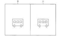
- each frame includes a first display frame (display frame L1) and a second display frame (display frame R1) arranged side by side.
- the display frame L1 and the display frame R1 are each compressed by half in the horizontal direction.
- a juxtaposed video including such a frame is supplied to the display device.
- the display device expands each of the display frame L1 and the display frame R1 shown in FIG. 2 twice in the horizontal direction.
- the display device decoding the juxtaposed video (for example, frame F1) shown in FIG. 2 the display frame L1 expanded to the original size shown in FIG. 3 and the original size shown in FIG. 4 are expanded.
- Display frame R1 is obtained. Then, all the expanded display frames including the display frame L1 and the display frame R1 are sequentially output in a predetermined order.
- the juxtaposed video is restored to the original, but the superimposed image P generated by the video supply device has a disadvantage that the original state is not reproduced.
- the superimposed image P is unnecessarily divided based on the arrangement of the display frames at the time of compression, and is subjected to unnecessary expansion processing, and in the example shown in FIG. Thereby, when the superimposed image P is displayed on the display device, it is not visually recognized in its original state (the state of the superimposed image P in FIG. 2).
- the juxtaposition video shown in FIG. 2 is a stereoscopic video
- the left-eye display frame and the right-eye display frame are arranged in one frame
- the display frame for the right eye is alternately output at a high speed after restoration. Therefore, the piece P1 of the superimposed image P shown in FIG. 3 and the piece P2 shown in FIG. 4 are horizontally expanded twice and displayed in an overlapping manner. For this reason, there is a problem that not only the superimposed image P cannot be provided so that the user can appropriately visually recognize, but also the visibility of the video on which the superimposed image P is superimposed is significantly reduced.
- a playback device that supplies a juxtaposed video to a display device, or a recording / playback device that further has a function of recording video is assumed.
- a playback device that supplies a juxtaposed video to a display device, or a recording / playback device that further has a function of recording video is assumed.
- the above problem is not a problem that occurs only when a stereoscopic video is handled. This similarly occurs when a juxtaposed video in which a plurality of display frames are juxtaposed in one frame in every layout is handled.
- juxtaposed video that does not handle stereoscopic video
- the following juxtaposed video can be considered.
- two different unrelated images are compressed in half in the horizontal direction.
- the compressed images are respectively referred to as a first display frame (display frame L1) and a second display frame (display frame R1).
- a juxtaposed video that juxtaposes these videos to the left and right to form one display frame.
- the present invention has been made in view of the above-described problems, and an object of the present invention is to provide a video supply apparatus capable of displaying a superimposed image together with a juxtaposed video without impairing visibility, and video supply To realize the method.
- the video supply device of the present invention is a video supply device that supplies video to a display device, and the video to be supplied to the display device is in each of the frames constituting the video.
- a superimposed image generating means for generating a superimposed image to be superimposed on the video when the display frame output by the display device is a video configured in a juxtaposed manner compressed in a predetermined direction and juxtaposed;
- Compression means for compressing the superimposed image generated by the superimposed image generation means in the same direction and the same compression ratio as the display frame, and at least one compression included in the frame for the superimposed image compressed by the compression means
- a superimposing unit that superimposes the display frame on the display frame relatively at the same position as the superimposition position on the video.
- the video supply device is configured such that the video to be supplied to the display device is compressed in a predetermined direction and arranged in parallel in each of the frames constituting the video.
- the operation is as follows. First, the superimposed image generation unit generates a superimposed image to be superimposed on the video. Next, the compression means compresses the superimposed image in the same direction and the same compression rate as the display frame. Subsequently, the superimposing unit superimposes the compressed superimposed image on the at least one compressed display frame included in the frame at the same position as the superimposed position on the video.
- the position of the compressed superimposed image on the compressed display frame is the same position as the superimposed position on the video” is because (i) the display is displayed on the compressed display frame.
- the positional relationship of the superimposed image with respect to the display frame is (ii) a video in an uncompressed state ( This means that when the uncompressed superimposed image is arranged on each frame, the positional relationship of the superimposed image with respect to the frame (for example, FIG. 8) is the same. That is, (i) when a display frame (for example, FIG.
- the video supply device can output a video in which a superimposed image compressed in the same direction and the same compression rate as the display frame is superimposed on the display frame.
- the video output in this way is supplied to the display device, even if the display device performs a process of expanding the display frame, only the superimposed image is not unnaturally expanded. As a result, it is possible to display the superimposed image together with the juxtaposed image without impairing the visibility.
- the video supply device of the present invention is a video supply device that supplies video to a display device, and the video to be supplied to the display device is in each of the frames constituting the video.
- the display frame output from the display device is a video composed of a juxtaposition method in which a plurality of juxtaposed images are compressed in a predetermined direction, a superimposed image generating unit that generates a superimposed image to be superimposed on the video, and compression Decompressing each display frame and restoring the video by connecting the decompressed display frames, and the same position as the superimposed position on the video on the display frame decompressed by the restoring means
- a superimposing unit that superimposes the superimposed image generated by the superimposed image generating unit.
- the video supply device is configured such that the video to be supplied to the display device is compressed in a predetermined direction and arranged in parallel in each of the frames constituting the video.
- the operation is as follows. First, the superimposed image generation unit generates a superimposed image to be superimposed on the video.
- the restoration means decompresses each compressed display frame and restores the video by connecting the decompressed display frames. Finally, the superimposing unit superimposes the generated superimposed image at the same position as the superimposing position on the video on the expanded display frame.
- the video supply device can display the normal size superimposed image (that is, the uncompressed superimposed image) on the display frame expanded to the original size (that is, the same size as the frame before being compressed). Can be output.
- the “superimposition position on the video” is the position of the superimposed image in the frame when the superimposed image is arranged on an uncompressed video (each frame) (for example, FIG. 8), the superimposed position when the superimposed image is arranged in the expanded display frame coincides with the superimposed position in the above-described frame (for example, FIGS. 8 and 13).
- the display device When the video output in this way is supplied to the display device, the display device does not need to perform decompression or compression processing, and sequentially outputs each display frame after decompression to display the video. Therefore, only the superimposed image is not unnaturally expanded. As a result, it is possible to display the superimposed image together with the juxtaposed image without impairing the visibility.
- the video supply device of the present invention is a video supply device that supplies video to a display device, and the video to be supplied to the display device is in each of the frames constituting the video.
- the image processing apparatus includes: a transmission unit configured to transmit a video configured in a juxtaposed manner to the display device and to transmit the superimposed image to the display device.
- the video supply device is configured such that the video to be supplied to the display device is compressed in a predetermined direction and arranged in parallel in each of the frames constituting the video.
- the operation is as follows. First, the superimposed image generation unit generates a superimposed image to be superimposed on the video. Subsequently, the transmission means transmits the video configured by the juxtaposition method to the display device, and transmits the generated superimposed image to the display device without being superimposed on the video.
- the display device can receive the video and the superimposed image in a state where they are not superimposed on each other. Since the display devices are not superimposed on each other, different display processes can be executed for the video and the superimposed image. Specifically, the display device performs processing for expanding the display frame to the original size for the video, and for the superimposed image of the normal size as it is without performing the processing for expansion. It can be superimposed on the display frame after expansion. Therefore, only the superimposed image is not unnaturally expanded. As a result, it is possible to display the superimposed image together with the juxtaposed image without impairing the visibility.
- the video supply method of the present invention is a video supply method for supplying video to a display device, wherein the video to be supplied to the display device is in each of the frames constituting the video.
- a superimposed image generating step for generating a superimposed image to be superimposed on the video when the display frame output by the display device is a video configured in a juxtaposed manner compressed in a predetermined direction and juxtaposed;
- a superimposing step for superimposing the image on one compressed display frame at the same position as the superimposition position on the video.
- the video supply method of the present invention is a video supply method for supplying video to a display device, wherein the video to be supplied to the display device is in each of the frames constituting the video.
- a superimposition step of superimposing the superimposed image generated in the superimposed image generation step on the position is a superimposed image generating step for supplying video to a display device, wherein the video to be supplied to the display device is in each of the frames constituting the video.
- the video supply method of the present invention is a video supply method for supplying video to a display device, wherein the video to be supplied to the display device is in each of the frames constituting the video.
- a superimposed image generating step for generating a superimposed image to be superimposed on the video when the display frame output by the display device is a video configured in a juxtaposed manner compressed in a predetermined direction and juxtaposed;
- the video supply device of the present invention is a video supply device that supplies video to a display device, and the video to be supplied to the display device is in each of the frames constituting the video.
- a superimposed image generating means for generating a superimposed image to be superimposed on the video when the display frame output by the display device is a video configured in a juxtaposed manner compressed in a predetermined direction and juxtaposed;
- Compression means for compressing the superimposed image generated by the superimposed image generation means in the same direction and the same compression ratio as the display frame, and at least one compression included in the frame for the superimposed image compressed by the compression means
- a superimposing unit that superimposes the display frame on the display frame relatively at the same position as the superimposition position on the video.
- the video supply device of the present invention is a video supply device that supplies video to a display device, and the video to be supplied to the display device is in each of the frames constituting the video.
- the display frame output from the display device is a video composed of a juxtaposition method in which a plurality of juxtaposed images are compressed in a predetermined direction, a superimposed image generating unit that generates a superimposed image to be superimposed on the video, and compression Decompressing each display frame and restoring the video by connecting the decompressed display frames, and the same position as the superimposed position on the video on the display frame decompressed by the restoring means
- a superimposing unit that superimposes the superimposed image generated by the superimposed image generating unit.
- the video supply device of the present invention is a video supply device that supplies video to a display device, and the video to be supplied to the display device is in each of the frames constituting the video.
- the image processing apparatus includes a transmission unit that transmits an image configured in a juxtaposed manner to the display device and transmits the superimposed image to the display device.
- the video supply method of the present invention is a video supply method for supplying video to a display device, wherein the video to be supplied to the display device is in each of the frames constituting the video.
- a superimposed image generating step for generating a superimposed image to be superimposed on the video when the display frame output by the display device is a video configured in a juxtaposed manner compressed in a predetermined direction and juxtaposed;
- a superimposing step for superimposing the image on one compressed display frame at the same position as the superimposition position on the video.
- the video supply method of the present invention is a video supply method for supplying video to a display device, wherein the video to be supplied to the display device is in each of the frames constituting the video.
- a superimposition step of superimposing the superimposed image generated in the superimposed image generation step on the position is a superimposed image generating step for supplying video to a display device, wherein the video to be supplied to the display device is in each of the frames constituting the video.
- the video supply method of the present invention is a video supply method for supplying video to a display device, wherein the video to be supplied to the display device is in each of the frames constituting the video.
- a superimposed image generating step for generating a superimposed image to be superimposed on the video when the display frame output by the display device is a video configured in a juxtaposed manner compressed in a predetermined direction and juxtaposed;
- FIG. 1 shows an embodiment of the present invention, is a functional block diagram showing a main configuration of a recording / reproducing apparatus.
- FIG. It shows a prior art and is a figure explaining the subject in a prior art. It shows a prior art and is a figure explaining the subject in a prior art. It shows a prior art and is a figure explaining the subject in a prior art. It is a block diagram which shows the hardware constitutions of the recording / reproducing apparatus of this invention. It is a block diagram which shows the hardware constitutions of the digital television of this invention. It is a figure which shows the specific example of a certain 1 frame in the 3D image
- FIG. 32 showing another embodiment of the present invention, is a functional block diagram illustrating a main configuration of a recording / reproducing device. It is a figure which shows the specific example of the image
- FIG. 24 is a functional block diagram illustrating still another embodiment of the present invention and showing a main configuration of a recording / reproducing apparatus and a main configuration of a digital television. It is a flowchart which shows the flow of a process of the video display system in further another embodiment of this invention.
- the video supply device of the present invention and the display device of the present invention construct a video display system for reproducing and displaying a video.
- the video supply device of the present invention is a device that supplies video to a display device.
- “supplying video to the display device” by the video supply device of the present invention includes supplying video directly to a display device that is communicably connected to the video supply device.
- the video supply device of the present invention “supplies video to the display device” means that the video supply device indirectly supplies it via another device (such as the device that processes the video) connected so as to be communicable. Including.
- the video supply device in the video display system of the present invention is capable of transmitting and receiving information to and from the display device via the appropriate connection means.
- the video supply device can supply the video reproduced by the device itself to the display device via the connection means.
- the display device can decode and output the video supplied from the video supply device to a monitor for display.
- the video supply apparatus of the present invention is not limited to this, but is a DVD (Digital Versatile Disc) recorder / player, HDD (Hard Disc drive) recorder / player, BD (Blu-ray Disc) recorder / player, digital video.
- the present invention can be applied to various playback devices or recording / playback devices that have a function of processing and playing at least a digital video signal and supplying it to the outside, such as a camera, a digital camera, and a personal computer (PC).
- a recording / reproducing apparatus such as a BD recorder is employed as an example of a video supply apparatus.
- a video processing device having a video processing function supplies processed video to a display device having a video display function
- this video processing device is included in the video supply device of the present invention.
- an image receiving device having a function of selecting and receiving an image for example, a tuner
- the image receiving device is connected to the image supply device of the present invention. included.
- an imaging device having a function of capturing a video for example, a CCD camera
- a display device having a video display function this imaging device is included in the video supply device of the present invention.
- the display device of the present invention is not limited to this, but can be applied to a digital television, a personal computer (PC), or the like that can process and display a digital video signal supplied from the outside.
- Digital TV includes LCD TV, plasma TV, organic EL TV, cathode ray tube TV, HDD (Hard disk drive) built-in TV, HDD player built-in TV, DVD (Digital Versatile Disk) built-in TV, DVD player built-in TV, BD ( Blu-ray Disc) TV with built-in recorder, TV with built-in BD player, and the like.
- a 3D liquid crystal television hereinafter referred to as a digital television
- a digital television is employed as an example of a display device.
- Embodiment 1 Embodiments of the present invention will be described with reference to FIGS. 1 to 14 as follows.
- FIG. 5 is a block diagram showing a hardware configuration of the recording / reproducing apparatus 100 according to the embodiment of the present invention.
- the recording / reproducing apparatus 100 includes a tuner 1, a communication interface 2, an infrared light receiving unit 3, an external device interface 4, a signal processing circuit group 5, a control unit 10, a recording / reproducing circuit group 11, and a storage unit 6.
- HD drive 60, ROM 61, RAM 62, and BD drive 63 are provided.
- the control unit 10 performs overall control of the above units according to a control signal input to the recording / reproducing apparatus 100.
- a control signal input to the recording / reproducing apparatus 100 a control signal input by an operation button (not shown) provided in the main body of the recording / reproducing apparatus 100, a control transmitted from a remote controller (not shown) and received by the infrared light receiving unit 3 Signals, control signals transmitted from external devices via the external device interface 4, control signals transmitted from network devices via the communication interface 2, and the like.
- a functional configuration for realizing the functions of the present invention in the control unit 10 will be described in detail later.
- the tuner 1 is a terrestrial digital broadcast tuner for receiving a broadcast program (broadcast video) broadcast by terrestrial digital broadcast.
- the tuner 1 includes, for example, an RF unit that converts a received signal into an analog baseband signal, an ADC unit that converts an analog baseband signal into a digital baseband signal, a demodulation unit that demodulates an MPEG stream, for example, from the digital baseband signal, and It can be configured by a decoding unit that decodes a video signal and an audio signal from an MPEG stream or the like.
- the MPEG stream demodulated by the tuner 1 is supplied to the recording / reproducing circuit group 11 through the bus under the control of the control unit 10.
- the video signal and the audio signal decoded by the tuner 1 are supplied to a video selector and an audio selector (not shown), respectively, and then the signal processing circuit group 5 To be supplied.
- the controller 10 controls which channel the tuner 1 selects as a demodulation target.
- the tuner 1 may be a double tuner that can simultaneously demodulate two MPEG streams broadcast via different channels.
- the tuner 1 is not limited to a double tuner, and may be, for example, a single tuner or a plurality of tuners including three or more tuners.
- the tuner 1 may be a satellite broadcast tuner for receiving a broadcast program broadcast by satellite broadcast.
- the communication interface 2 is an interface for connecting the recording / reproducing apparatus 100 to a network or various network devices.
- An example of the communication interface 2 is a LAN interface.
- the infrared light receiver 3 receives an infrared control signal transmitted from a remote controller (not shown) for remotely operating the recording / reproducing apparatus 100.
- the external device interface 4 is an interface for connecting an external device to the recording / reproducing device 100.
- Examples of the external device interface 4 include HDMI (High Definition Multimedia Interface), iLink, and the like.
- the signal processing circuit group 5 includes a circuit group for processing the video signal and the audio signal decoded by the tuner 1.
- the signal processing circuit group 5 includes, for example, a video processing circuit 15, a superimposed image generation circuit 16, a superimposition processing circuit 22, an audio processing circuit 17, and the like, similar to the signal processing circuit group 5 of the digital television 200 illustrated in FIG. 6. Contains.
- the video processing circuit 15 processes the video signal supplied from the video selector as necessary under the control of the control unit 10. Specifically, for example, the video processing circuit 15 executes image quality adjustment processing for adjusting the luminance, sharpness, contrast, and the like of the video represented by the video signal. Alternatively, the video processing circuit 15 may execute a scaling process that similarly enlarges or reduces the size of the video represented by the video signal. Furthermore, the video processing circuit 15 expands the display frame from each frame of the juxtaposed video and rearranges the expanded display frames in a predetermined order according to an instruction from the control unit 10 as necessary. May be executed.
- the superimposed image generation circuit 16 generates (renders) a superimposed image based on the superimposed data supplied from the control unit 10 under the control of the control unit 10.
- the superimposed image generated by the superimposed image generation circuit 16 information on the operation (recording, reproduction, pause, fast forward, etc.) of the recording / reproducing apparatus 100, such as the superimposed image P shown in FIG.
- the superimposed image represents the process execution state of the recording / reproducing apparatus 100 when the recording / reproducing apparatus 100 as the apparatus executes various processes in response to a user's instruction input.
- the process execution state is information indicating that the recording / reproducing apparatus 100 is executing a certain process in response to a user instruction input.
- the superimposed image may represent a playback program title.
- an electronic program guide, a menu screen, an operation screen, etc. may be generated as a superimposed image.
- the superimposed image can represent various pieces of information regarding the processing target video that is being processed by the recording / reproducing apparatus 100.
- SVG Scalable Vector Graphics
- the superimposed image generated by the superimposed image generation circuit 16 is superimposed on the video signal supplied from the video processing circuit 15 by the superimposition processing circuit 22.
- the superimposition processing circuit 22 superimposes the superimposed image generated by the superimposed image generation circuit 16 on the video signal supplied from the video processing circuit 15 under the control of the control unit 10.
- the video signal on which the superimposed image is superimposed is supplied to the digital television 200 via the external device interface 4.
- the audio processing circuit 17 performs volume adjustment processing or sound quality adjustment processing on the audio signal supplied from the audio selector as necessary under the control of the control unit 10.
- the volume adjustment processing refers to changing the volume of the voice represented by the voice signal by processing the voice signal.
- the sound quality adjustment processing refers to changing the frequency characteristics of the sound represented by the sound signal by processing the sound signal (for example, low frequency emphasis or high frequency emphasis).
- the audio signal processed by the audio processing circuit 17 is supplied to the digital television 200 through the external device interface 4 together with the video signal.
- the storage unit 6 stores various data read by the control unit 10 in order for the recording / reproducing apparatus 100 to operate.
- the storage unit 6 of the recording / reproducing apparatus 100 includes, for example, an HD drive 60, a ROM 61, a RAM 62, and a BD drive 63.
- the HD drive 60 realizes information recording or reproduction with respect to HD (Hard Disc). Similar to the BD drive 63 shown in FIG. 5, the HD drive 60 includes the optical disc 7 (in this case, the optical disc is HD) and the optical pickup 9.
- the ROM 61 is a readable and non-writable memory in which fixed data such as a program executed by the control unit 10 is stored.
- the RAM 62 is a readable and writable memory in which variable data such as data referred to by the control unit 10 for calculation and data generated by the control unit 10 by calculation is stored.
- the ROM 61 stores (1) a control program executed by the control unit 10, (2) an OS program, and (3) an application program for the control unit 10 to execute various functions.
- the RAM 62 stores (4) various data read when the application program is executed.
- the BD drive 63 realizes recording or reproduction of information with respect to a BD (Blu-ray Disc) as an optical disc.
- the BD drive 63 includes an optical disc 7 and an optical pickup 9.
- the optical pickup 9 includes an optical head 8 and records and reproduces data on the optical disc 7.
- the optical head 8 is movable in the optical axis direction and the radial direction that is the radial direction of the optical disc 7.
- the optical head 8 writes information by irradiating a predetermined recording position of the optical disc 7 with a light beam (laser beam) for recording information.
- a light beam laser beam
- the optical head 8 detects a reflected light obtained from the optical disc 7 by irradiating a predetermined reading position of the optical disc 7 with a light beam for reproduction at the time of reproduction, and the recording / reproducing circuit group 11 ( Output to the reproducing circuit 14).
- the recording / reproducing circuit group 11 includes a circuit group for recording and reproducing information with respect to the optical disc 7 under the control of the control unit 10.
- the recording / reproducing circuit group 11 includes, for example, a pickup driving circuit 12, a laser driving circuit 13, a reproducing circuit 14, and the like.
- the pickup drive circuit 12 drives the optical pickup 9 in accordance with a control signal from the control unit 10.
- the pickup driving circuit 12 drives the optical pickup 9 to move the optical pickup 9 with respect to a track (not shown) of the optical disc 7, that is, in the radial direction and the optical axis direction.
- the laser drive circuit 13 controls the output of the recording light beam or the reproduction light beam emitted from the optical head 8.
- the reproduction circuit 14 converts the reflected light detected by the optical head 8 into a reproduction signal and outputs it to the control unit 10.
- FIG. 6 is a block diagram showing a hardware configuration of the digital television 200 in the embodiment of the present invention.
- the digital television 200 includes a tuner 1, a communication interface 2, an infrared light receiving unit 3, an external device interface 4, a signal processing circuit group 5, an LCD 19, an LCD controller 18, a speaker 21, a control unit 20, and a storage.
- a ROM 61 and a RAM 62 are provided as the unit 6.
- each component shown in FIG. 6 operates under the control of the control unit 20 so as to be compatible with the digital television 200, and the same reference numerals of the recording / reproducing apparatus 100 shown in FIG. Same as component. Therefore, the description which overlaps with the description about the component mentioned above is abbreviate
- the control unit 20 performs overall control of the above units according to a control signal input to the digital television 200.
- the functional configuration for realizing the functions of the present invention in the control unit 20 will be described in detail later.
- the signal processing circuit group 5 is a circuit group for processing the video signal and audio signal decoded by the tuner 1 or the video signal and audio signal supplied from the recording / reproducing apparatus 100 via the external device interface 4. Become.
- the signal processing circuit group 5 is, for example, the video processing circuit 15, the superimposed image generation circuit 16, the superimposition processing circuit 22, and the audio processing circuit 17 in the same manner as the signal processing circuit group 5 of the recording / reproducing apparatus 100 shown in FIG. Is included.
- the video processing circuit 15 expands the display frame from each frame of the juxtaposed video according to the instruction of the control unit 20 and arranges the expanded display frames in a predetermined order as necessary.
- the restoration process to be replaced is executed.
- the video processing circuit 15 restores them together.
- the superimposed image generation circuit 16 renders a superimposed image generated by the own device (digital television 200) under the control of the control unit 20.
- the superimposed image generated by the superimposed image generation circuit 16 is superimposed on the video signal supplied from the video processing circuit 15 by the superimposition processing circuit 22.
- the video signal on which the superimposed image is superimposed is supplied from the superimposition processing circuit 22 to the LCD controller 18.
- the audio signal processed by the audio processing circuit 17 is supplied to the LCD controller 18 together with the video signal.
- the LCD controller 18 drives the LCD 19 based on the video signal supplied from the video processing circuit 15 so as to display the video represented by the video signal.
- the LCD controller 18 displays the video represented by the video signal based on the video signal with the superimposed image supplied from the superimposition processing circuit 22.
- the LCD 19 is driven to display.
- a 3D liquid crystal television is adopted as an example of the digital television 200.
- the digital television 200 employs the LCD 19 as a display and the LCD controller 18 as a display controller. Therefore, when a television other than the 3D liquid crystal television is adopted as the digital television 200, a display and a display controller corresponding to the television are adopted.
- the speaker 21 outputs the sound represented by the sound signal based on the sound signal supplied from the sound processing circuit 17.
- the speaker 21 is driven to output sound by an amplifier (not shown).
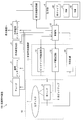
- FIG. 1 is a functional block diagram showing a main configuration of the recording / reproducing apparatus 100.
- the control unit 10 of the recording / playback apparatus 100 includes, as functional blocks, a playback control unit 31, a recording control unit 32, a video acquisition unit 41, a display mode control unit 42, a superimposed image generation unit 43, and an image compression unit. 44 and a superimposing unit 45.
- the reproduction control unit 31 and the recording control unit 32 function as the recording / reproduction control unit 30.
- the recording / reproducing control unit 30 realizes a recording / reproducing function.
- the recording / reproducing function controls the recording / reproducing circuit group 11 and the BD drive 63 or the HD drive 60 to record and reproduce information on the optical disc. Refers to the function to be performed.
- the reproduction control unit 31 performs reproduction control on the loaded optical disc 7. That is, the pickup driving circuit 12, the laser driving circuit 13, and the reproducing circuit 14 are controlled to read data stored in the optical disc 7.
- the recording control unit 32 performs recording control on the loaded optical disc 7. That is, the pickup driving circuit 12 and the laser driving circuit 13 are controlled to write data at the storage position of the optical disc 7.
- the video acquisition unit 41, the display mode control unit 42, the superimposed image generation unit 43, the image compression unit 44, and the superposition unit 45 function as the video processing control unit 40.
- the video processing control unit 40 realizes a video processing function.
- the video processing function controls the signal processing circuit group 5 and supplies it to the digital television 200 (or video signal and audio). Signal).
- the video acquisition unit 41 acquires a video signal from each unit controlled by the control unit 10. Specifically, the video acquisition unit 41 is a video signal acquired via the tuner 1, the communication interface 2, or the external device interface 4, a video signal reproduced by the recording / reproducing circuit group 11, or a storage unit. The video signal stored in 6 is acquired. The video acquisition unit 41 supplies the acquired video signal to the display mode control unit 42 and the superimposition unit 45.
- the display mode control unit 42 determines, based on the acquired video signal, whether the video represented by the video signal is handled as a frame sequential video or a juxtaposed video.
- the frame sequential method differs from the juxtaposed method described above in that each frame constituting the video has a one-to-one correspondence with the display frame, and the frames are arranged one by one in the order in which the display frames are displayed.
- This method In the present embodiment, as an example, hereinafter, a frame sequential video that is not intended for stereoscopic vision is referred to as a 2D video, and a juxtaposed video (stereoscopic video) that is intended for stereoscopic vision is referred to as a 3D video.
- the display mode control unit 42 performs appropriate processing on the video signal to determine whether it is a 2D video or a 3D video. Further, in the case of 3D video, the display mode control unit 42 determines the layout of the display frame, such as whether it is a side-by-side method, a top-and-bottom method, or another specific juxtaposition method. Judging.
- the display mode control unit 42 can determine the format of the input video based on, for example, a technique disclosed in Patent Document 1 or 2. Alternatively, the input video method may be determined based on a method designated in advance by the user. In the configuration in which the video system is specified by the user, the display mode control unit 42 controls the video processing so that the video is recognized by the specified system, for example, according to the control signal received via the infrared light receiving unit 3. The display mode of each part of the part 40 is switched. Alternatively, when the input video is a broadcast program, the display mode control unit 42 may determine a method based on program information received by the tuner 1 and accompanying the broadcast program. . The program information includes, for example, information indicating that it is a 3D video, information indicating a method, and the like.
- the method determined by the display mode control unit 42 is transmitted to the image compression unit 44 and the superimposition unit 45 of the video processing control unit 40.
- the superimposed image generation unit 43 controls the superimposed image generation circuit 16 to generate a superimposed image to be superimposed on the input video. For example, the superimposed image generation unit 43 generates a superimposed image to be superimposed on the video at a necessary timing according to the control signal received via the infrared light receiving unit 3. For example, the superimposed image is generated by SVG to be displayed at a predetermined position of the frame.
- the image compression unit 44 controls the superimposed image generation circuit 16 to compress the superimposed image generated by the superimposed image generation unit 43.
- the image compression unit 44 is generated at the same compression rate and the same compression direction as the display frame in accordance with the video format (display frame layout in each frame) recognized by the display mode control unit 42. Compress the superimposed image.
- the image compression unit 44 displays the generated superimposed image. , Compressed in half in the horizontal direction.
- the superimposed image compressed by the image compression unit 44 is supplied to the superposition unit 45.
- the superimposing unit 45 controls the video processing circuit 15, the superimposed image generating circuit 16, and the superimposing processing circuit 22 to display the superimposed image generated by the superimposed image generating unit 43 on the video acquired by the video acquiring unit 41.
- Superimpose The superimposing unit 45 controls the superimposition position and the superimposition timing so that the superimposed image with the predetermined display position is displayed at the predetermined position of each frame of the video.
- the video signal processed by the superimposing unit 45 is output to the external device interface 4 in a state where the superimposed image is superimposed. Then, it is supplied to the digital television 200 via the external device interface 4.
- Each unit shown as the functional block is a program stored in a storage device such as a ROM (read only memory) 61 by a control unit 10 realized by a CPU (central processing unit). It can be realized by reading and executing the above.
- each unit of the video processing control unit 40 as a functional block shown in FIG. 1 realizes the above-described functions by controlling the signal processing circuit group 5 shown in FIG. To do.
- the tuner 1 has already acquired a broadcast program that is a juxtaposed video, stored in the optical disc 7 of the BD drive 63, and an instruction to reproduce the broadcast program is received via the infrared light receiver 3. Then, the case where the data is input to the recording / reproducing apparatus 100 will be considered.
- the video acquisition unit 41 acquires the 3D video (video signal) of the broadcast program read from the optical disc 7 by the reproduction control unit 31.
- FIG. 7 is a diagram illustrating an example of one frame in the 3D video acquired by the video acquisition unit 41.
- the left-eye display frame 70 and the right-eye display frame 71 are horizontally compressed and arranged on the left and right for each frame. That is, the side-by-side method is adopted in the 3D video.
- the display mode control unit 42 recognizes the input video format.
- the superimposed image generation unit 43 generates a superimposed image corresponding to the event using a predetermined event as a trigger.
- the predetermined event is not particularly limited, for example, when an input of a control signal is received from a remote controller operated by the user, or when the recording / reproducing apparatus 100 starts a new operation.
- the superimposed image generating unit 43 may generate a superimposed image so that a mark indicating “being reproduced” is displayed.
- the superimposed image generation unit 43 may generate a superimposed image so that a mark indicating “suspended” is displayed.
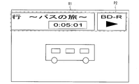
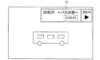
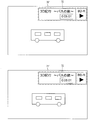
- the superimposed image 72 is an image including the title of the broadcast program being reproduced and a mark indicating that the program is being reproduced.
- the image compression unit 44 compresses the superimposed image generated by the superimposed image generation unit 43 in accordance with the method (or display frame layout) determined by the display mode control unit 42.
- the image compression unit 44 similarly performs a process of compressing the superimposed image 72 shown in FIG.
- FIG. 9 is a diagram illustrating an example of the compressed superimposed image generated by the image compression unit 44. As shown in FIG. 9, the image compression unit 44 compresses the superimposed image 72 to generate a compressed superimposed image 73.
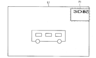
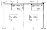
- FIG. 10 is a diagram illustrating a specific example of one frame in the video after the superimposing unit 45 superimposes the compressed superimposed image.
- the display position and the display size of the superimposed image are determined in advance according to the content.
- the superimposed image 72 shown in FIG. 8 is predetermined with (Xo, Yo) as the starting point when the upper left end of the frame is the origin (0, 0) and the lower right end of the frame is (Xmax, Ymax). It is determined to be displayed in size.
- the superimposing unit 45 superimposes the compressed superimposed image 73 at the same position as the display position on the frame of the original superimposed image 72 when superimposing the compressed superimposed image 73 on each display frame. .
- the superimposing unit 45 sets the display position of the compressed superimposed image 73 to be superimposed on the left-eye display frame 70 arranged on the left of the frame, that is, the start point (X L , Y L ) as follows.
- the superimposing unit 45 obtains the display position of the compressed superimposed image 73 to be superimposed on the right-eye display frame 71 arranged on the right side of the frame, that is, the start point (X R , Y R ) as follows.
- the above formula can be applied to the case where the display frame is compressed in half in the horizontal direction (X direction).
- the superimposing unit 45 has the start point ( XL , Y L ) and the starting point (X R , Y R ) are determined as follows. In this case, it is assumed that the left-eye display frame 70 is disposed above and the right-eye display frame 71 is disposed below.
- the configuration has been described in which the superimposing unit 45 superimposes the compressed superimposed image 73 on both the left-eye display frame 70 and the right-eye display frame 71.
- the recording / reproducing apparatus 100 of the present invention is not limited thereto. The configuration is not limited to the above.
- the superimposing unit 45 may superimpose the compressed superimposed image 73 on at least one of the left-eye display frame 70 and the right-eye display frame 71 that are divided into two. Since the left-eye display frame 70 and the right-eye display frame 71 are alternately displayed at high speed, if the post-compression superimposed image 73 is arranged on either the left-eye display frame 70 or the right-eye display frame 71, The user can visually recognize the superimposed image without any problem. However, in order to display both eyes without a sense of incongruity, it is desirable that the superimposing unit 45 arranges the compressed superimposed image 73 on both the left-eye display frame 70 and the right-eye display frame 71 as described above.
- the superimposing unit 45 may specify a starting point at the same position as the original on each display frame, and may further add parallax to the superimposed image.
- the superimposing unit 45 adds the superimposed position of the compressed superimposed image 73 superimposed on the left-eye display frame 70 and the superimposed position of the compressed superimposed image 73 superimposed on the right-eye display frame 71 in order to add parallax to the superimposed image. You may fine-tune based on the specified starting point.
- a method of adding parallax to the compressed superimposed image 73 for example, techniques disclosed in Patent Documents 3 and 4 can be employed.
- the video signal to which the superimposed image is added is supplied to the digital television 200 via the external device interface 4.
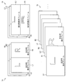
- 11 and 12 are diagrams illustrating an example of an operation in which the video restoration unit of the digital television 200 restores 3D video.
- the video restoration unit expands the display frames L1, R1, L2, R2, L3, R3.
- the decompressed display frames are arranged in the same order to restore the video.
- a post-restoration video 75 in the figure shows a frame sequential video restored by the video restoration unit.
- the video restoration unit expands the display frames L1, R1, L2, R2, L3, R3.
- the display frames are arranged in the same order to restore the video, and the restored video 75 is generated.
- the video restoration unit expands the display frames L1, R1, L2, R2, L3, R3, L4, R4, L5, R5, L6, R6... Twice in the horizontal direction and the vertical direction, respectively.
- the video restoration unit may restore the video by arranging the expanded display frames in the same order, and obtain the restored video 75 shown in FIG.
- the superimposing unit 45 of the recording / reproducing apparatus 100 converts the compressed superimposed image 73 compressed by 1/2 in the vertical and horizontal directions into all four display frames or one of the left-eye display frame and the right-eye display frame (2 On the sheet).
- the superimposed image 72 generated by the recording / reproducing apparatus 100 is compressed at the same compression rate in the same compression direction as the display frame in the juxtaposed video. In this state (superimposed image 73 after compression), it can be superimposed at the same relative position. Therefore, when such 3D video is restored on the digital television 200 side, the superimposed image 72 is displayed on the LCD 19 of the digital television 200 in the same state as the original superimposed image 72 without unnecessary division and expansion. Is done.
- FIG. 13 is a diagram showing an example of the screen of the LCD 19 when the digital television 200 restores the video supplied from the recording / reproducing apparatus 100 and outputs it to the LCD 19.
- the video restoration unit of the digital television 200 restores the 3D video (3D video shown in FIG. 10) supplied from the recording / playback device 100, the superimposed image 72 is subjected to unnecessary segmentation and expansion. Without being restored.
- the recording / reproducing apparatus 100 of the present invention it is possible to realize a video display system capable of displaying a superimposed image together with a juxtaposed video without impairing visibility.
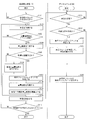
- FIG. 14 is a flowchart showing the flow of processing in the video display system in the present embodiment.
- the reproduction control unit 31 starts a video reproduction process, and the video is displayed as a video.
- This is supplied to the video acquisition unit 41 of the processing control unit 40.
- the video acquisition unit 41 acquires the video signal of the video to be played (for example, FIG. 7) supplied from the playback control unit 31 (S102).
- the video acquired by the video acquisition unit 41 is transmitted to the digital television 200 via the external device interface 4. (S110).
- the video is supplied to the digital television 200 without being processed in the superimposing unit 45 (that is, without any superimposed image).
- the superimposed image generation unit 43 when an event that triggers generation of a superimposed image occurs (YES in S103), the superimposed image generation unit 43 generates a superimposed image (for example, FIG. 8) corresponding to the generated event (S104).
- the recording / reproducing apparatus 100 may be configured to transit to S104: a step of generating a superimposed image according to all video reproduction instructions without branching to S110 after S102.
- the display mode control unit 42 determines the format of the video acquired in S102 at any time from the completion of S102 to the start of S106 or S107.
- the display mode control unit 42 determines that the video system is not the juxtaposed system, that is, when it is determined that the video system is the frame sequential system (NO in S105)
- the superimposing unit 45 is acquired by the video acquisition unit 41.
- the superimposed image generated in S104 is superimposed on the video (S106), and the video is output.
- the video output by the superimposing unit 45 is supplied to the digital television 200 via the external device interface 4 (S110).
- the display mode control unit 42 determines that the video system is the juxtaposed system (YES in S105)
- the display mode control unit 42 further specifies the layout of the display frame in the video (S107).
- S107 the layout of the display frame in the video
- the image compression unit 44 compresses the superimposed image generated in S104 according to the specified layout of the display frame (S108). For example, here, as with the specified display frame, the image compression unit 44 generates a compressed superimposed image (for example, FIG. 9) compressed in half in the horizontal direction.
- the superimposing unit 45 superimposes the compressed superimposed image generated in S108 on the video acquired in S102 (S109).
- the video after the superimposed image is added (for example, FIG. 10) is output to the external device interface 4 and supplied to the digital television 200 via the external device interface 4 (S110).
- the recording / reproducing apparatus 100 for example, unless an input of a video end instruction is received from a remote controller operated by the user (NO in S111), the recording / reproducing apparatus 100 performs the above-described processing (ie, video reproduction). Continue. That is, the process returns to step S102. On the other hand, when the input of the video end instruction is accepted (YES in S111), the video playback ends.
- the display mode control unit of the control unit 20 of the digital television 200 is acquired.
- the video system is determined (S202).
- the signal processing circuit group 5 of the digital television 200 sequentially sequentially displays each frame of the frame sequential system.
- the image is output and displayed on the LCD 19 (S205).
- the display mode control unit determines that the video method is the juxtaposition method (YES in S202)
- the display mode control unit specifies the layout of the display frame in the video (S203).
- the video restoration unit restores the video acquired in S201 according to the layout of the display frame specified in S203. Specifically, the display frames arranged in each frame of the video are each doubled in the horizontal direction (S204). Then, the expanded display frames are arranged in a predetermined order.
- the video restoration unit obtains a restored video 75 from the 3D video 74.
- each display frame is sequentially output and displayed on the LCD 19 (S205).
- the superimposed image generated by the recording / reproducing apparatus 100 is relatively compressed in the same compression direction as the display frame in the juxtaposed video at the same compression rate (compressed superimposed image 73). It can be superimposed at the same position. Therefore, when such 3D video is restored on the digital television 200 side, the superimposed image 72 is displayed on the LCD 19 of the digital television 200 in the same state as the original superimposed image 72 without unnecessary division and expansion. Is done.
- the digital television 200 only restores the juxtaposed video supplied from the recording / reproducing apparatus 100 as usual. That is, in order for the superimposed image of the recording / reproducing apparatus 100 to be properly displayed on the digital television 200, the recording / reproducing apparatus 100 of the present invention is sufficient, and it is not necessary to improve the configuration on the digital television 200 side.
- the digital television 200 is usually more expensive than the recording / reproducing apparatus 100 and is more widely distributed and popularized, there are significant advantages for both the manufacturer and the user. This is because the video display system of the present invention can be realized more inexpensively and easily simply by introducing the recording / reproducing apparatus 100.
- the recording / reproducing apparatus 100 is configured to supply the video to the digital television 200 in a juxtaposed manner, and the recording / reproducing apparatus 100 also compresses the superimposed image in accordance with the compressed display frame. explained.
- the present invention is not limited to the above configuration.
- the recording / reproducing apparatus 100 of the present invention may be configured to restore a juxtaposed video and supply it to the digital television 200 in a frame sequential manner, and to add a superimposed image prior to the supply. .
- An embodiment of the present invention with respect to this configuration will be described below with reference to FIGS.
- FIG. 15 is a functional block diagram showing the main configuration of the recording / reproducing apparatus 100.
- members having the same functions as those in the drawings described in the first embodiment are given the same reference numerals, and duplicate descriptions are omitted as appropriate.
- the control unit 10 of the recording / reproducing apparatus 100 in the present embodiment includes, as functional blocks, a reproduction control unit 31, a recording control unit 32, a video acquisition unit 41, a display mode control unit 42, and a superimposed image generation unit 43.
- a video restoring unit 46 and a superimposing unit 45 are provided. That is, as compared with the recording / reproducing apparatus 100 shown in FIG. 1, a video restoration unit 46 is provided instead of the image compression unit 44.
- the video restoration unit 46 controls the video processing circuit 15 to restore the juxtaposed video to the frame sequential video.
- the video restoration unit 46 restores the video according to the layout of the display frame specified by the display mode control unit 42.
- the video restoration unit 46 expands each display frame included in each frame of the video twice in the horizontal direction. Then, the display frames expanded as they are are arranged in a predetermined order and output to the superimposing unit 45.
- the video restoration unit 46 obtains a restored video 75 from the 3D video 74 as shown in FIG. More specifically, when the 3D video shown in FIG.
- the video restoration unit 46 performs the decompressed left-eye display frame 70 ′ and the decompressed right-eye display frame 71 as shown in FIG. Generate '.
- the stretched left-eye display frame 70 'and the stretched right-eye display frame 71' are obtained by horizontally stretching the left-eye display frame 70 and the right-eye display frame 71 of FIG. .
- the superimposing unit 45 When the superimposed image is output from the superimposed image generating unit 43, the superimposing unit 45 adds the superimposed image to the frame sequential video output from the video restoring unit 46 and outputs the video to the external device interface 4. To do. For example, when the superimposed image 72 shown in FIG. 8 is output, the superimposing unit 45 superimposes it on the default display position of each display frame as shown in FIG.
- the video (FIG. 17) to which the superimposed image generated by the recording / playback apparatus 100 is added is supplied to the digital television 200 via the external device interface 4 as a frame sequential video.
- FIG. 18 is a flowchart showing the flow of processing in the video display system in the present embodiment.
- the reproduction control unit 31 starts the video reproduction process, and the video is This is supplied to the video acquisition unit 41 of the processing control unit 40.
- the video acquisition unit 41 acquires the video signal of the video to be played (for example, FIG. 7) supplied from the playback control unit 31 (S302).
- the display mode control unit 42 determines the format of the video acquired in S302 (S303).
- the display mode control unit 42 determines that the video method is not the juxtaposition method, that is, when the display mode control unit 42 determines that the video method is a frame sequential method (NO in S303)
- the video is subjected to processing by the video restoration unit 46. Without being supplied to the superimposing unit 45.
- the display mode control unit 42 determines that the video system is the juxtaposition system (YES in S303), the display mode control unit 42 further specifies the layout of the display frame in the video (S304). .
- the side-by-side method of length ⁇ width 1 ⁇ 2 is specified.
- the video restoration unit 46 restores the juxtaposed video according to the judgment of the display mode control unit 42 (S305). For example, as illustrated in FIG. 16, the video restoration unit 46 generates a stretched left-eye display frame 70 ′ and a stretched right-eye display frame 71 ′. The restored video is supplied to the superimposing unit 45.
- the video acquired by the video acquisition unit 41 is transmitted to the digital television 200 via the external device interface 4. (S309).
- the video is supplied to the digital television 200 without being processed in the superimposing unit 45 (that is, without any superimposed image).
- the superimposed image generation unit 43 when an event that triggers generation of a superimposed image occurs (YES in S306), the superimposed image generation unit 43 generates a superimposed image (for example, FIG. 8) corresponding to the generated event (S307).
- the generated superimposed image 72 is supplied to the superimposing unit 45.
- the superimposing unit 45 superimposes the superimposed image generated in S307 on the video acquired by the video acquiring unit 41 (S308), and outputs the video (for example, FIG. 17).
- the video output by the superimposing unit 45 is supplied to the digital television 200 via the external device interface 4 (S309).
- the recording / reproducing apparatus 100 for example, unless an input of a video end instruction is received from a remote controller operated by the user (NO in S310), the recording / reproducing apparatus 100 performs the above-described processing (ie, video reproduction). Continue. That is, the process returns to step S302. On the other hand, when input of a video end instruction is accepted (YES in S310), video playback ends.
- the recording / reproducing apparatus 100 may be configured to execute step S307 of generating a superimposed image for all restored videos without branching to S309 after S305. .
- the superimposed image generated by the superimposed image generation unit 43 is superimposed after the juxtaposed video is restored by the video restoration unit 46, and the superimposed image remains as it is before restoration. There is no overlap.
- the superimposed image is subjected to unnecessary division or unnecessary expansion processing, and a video signal obtained by synthesizing the 3D video and the superimposed image generated by the recording / reproducing apparatus 100 is used as a conventional frame sequential video. It becomes possible to supply to the digital television 200 in the same manner as.
- the digital television 200 may process the received video in the same manner as a conventional frame sequential video and display it on the LCD 19.
- the digital television 200 does not even need a function for restoring juxtaposed video. That is, in order for the superimposed image of the recording / reproducing apparatus 100 to be properly displayed on the digital television 200, the recording / reproducing apparatus 100 of the present invention is sufficient, and it is not necessary to improve the configuration on the digital television 200 side. Further, the digital television 200 is not required to have a function for restoring juxtaposed video. In view of the fact that the digital television 200 is usually more expensive than the recording / reproducing apparatus 100 and is more widely distributed and popularized, there are significant advantages for both the manufacturer and the user. This is because the video display system of the present invention can be realized more inexpensively and easily simply by introducing the recording / reproducing apparatus 100.
- Embodiment 3 when the superimposed image of the recording / reproducing apparatus 100 is added to the video, the superimposed image is added in the recording / reproducing apparatus 100.
- the present invention is not limited to the above configuration.
- the recording / reproducing apparatus 100 of the present invention may be configured to separately supply the superimposed image generated by the recording / reproducing apparatus 100 and the video to be displayed to the digital television 200 without combining them.
- the digital television 200 of this invention may be the structure which superimposes and displays the received superimposed image on the received image
- FIG. An embodiment of the present invention with respect to this configuration will be described below with reference to FIGS. 7, 8, 16, 17, 19, and 20.
- the hardware configurations of the recording / reproducing apparatus 100 and the digital television 200 in the present embodiment are the same as those described in the first embodiment, and a description thereof will be omitted.
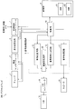
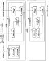
- FIG. 19 is a functional block diagram showing a main part configuration of the recording / reproducing apparatus 100 and a main part configuration of the digital television 200.
- members having the same functions as those in the drawings described in the first and second embodiments are given the same reference numerals, and redundant descriptions are omitted as appropriate.
- the control unit 10 of the recording / reproducing apparatus 100 in the present embodiment includes a reproduction control unit 31, a recording control unit 32, a video acquisition unit 41, a superimposed image generation unit 43, and a transmission control unit as functional blocks. 47 is provided.
- the transmission control unit 47 supplies the video output from the video acquisition unit 41 to the digital television 200 via the external device interface 4.
- the transmission control unit 47 supplies the superimposed image output from the superimposed image generation unit 43 to the digital television 200 using the external device interface 4 or other communication means.
- the transmission control unit 47 transmits the video and the superimposed image to the digital television 200 as separate data without combining them. However, the transmission control unit 47 supplies the superimposed image to the digital television 200 in association with the video so that the superimposed image is definitely combined with the video.
- control unit 20 of the digital television 200 in the present embodiment includes a video acquisition unit 41, a display mode control unit 42, a superimposition unit 45, a video restoration unit 46, and a superimposed image acquisition unit 48 as functional blocks. .
- Each of the above-described units of the control unit 20 functions as the video processing control unit 40.
- the video processing control unit 40 of the digital television 200 realizes a video processing function.
- the video processing function controls the signal processing circuit group 5 and supplies it to the LCD 19 (or video signal). And an audio signal).
- each part of the control part 20 shown as the said functional block is a program (RAM (random) memory
- RAM random memory
- CPU central (processing) unit
- each unit of the video processing control unit 40 of the control unit 20 as a functional block shown in FIG. 19 controls the signal processing circuit group 5 shown in FIG.
- the following functions are realized.
- the video acquisition unit 41 acquires the video supplied from the transmission control unit 47 of the recording / reproducing apparatus 100 via the external device interface 4.
- the superimposed image acquisition unit 48 acquires a superimposed image of the recording / reproducing apparatus 100 associated with the video supplied from the transmission control unit 47.
- the superimposed image acquisition unit 48 outputs the acquired superimposed image to the superimposition unit 45.
- the video restoration unit 46 decompresses and restores the display frames arranged in each frame of the video when the method determined by the display mode control unit 42 is the juxtaposition method. If the method determined by the display mode control unit 42 is the frame sequential method, the video acquired by the video acquisition unit 41 is output to the superimposing unit 45 without performing processing such as decompression.
- the superimposing unit 45 superimposes the superimposed image on the frame sequential video supplied from the video restoration unit 46.
- the video output by the superimposing unit 45 is output to the LCD 19 via the LCD controller 18.
- the transmission control unit 47 of the recording / reproducing apparatus 100 displays the video and the superimposed image at an appropriate timing while separately supplying the video and the superimposed image. You may go.
- the transmission control unit 47 displays time information at the time when the superimposed image is generated, that is, the time at which the event occurs.
- the superimposed image is stored in association with the first frame, and the superimposed image is supplied to the digital television 200.
- the display frame time associated with each display frame of the video and the first frame of the superimposed image are associated. Check the current time information. In this way, the digital television 200 can synthesize and output the superimposed image from the display frame time that matches the time information. Therefore, it is possible to realize the digital television 200 that can superimpose the superimposed image on the video at an appropriate timing while the video and the superimposed image are separately supplied.
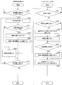
- FIG. 20 is a flowchart showing the flow of processing in the video display system according to this embodiment.
- the reproduction control unit 31 starts a video reproduction process, and the video is displayed as a video.
- This is supplied to the video acquisition unit 41 of the processing control unit 40.
- the video acquisition unit 41 acquires the video signal of the video to be played (for example, FIG. 7) supplied from the playback control unit 31 (S502).
- the transmission control unit 47 uses the external device interface 4 as it is with the video acquired by the video acquisition unit 41 as it is. Via the digital TV 200 (S504). That is, here, the transmission control unit 47 supplies the video to the digital television 200 without associating any superimposed image.
- the superimposed image generation unit 43 when an event that triggers generation of a superimposed image occurs (YES in S503), the superimposed image generation unit 43 generates a superimposed image (for example, FIG. 8) corresponding to the generated event (S505).
- the generated superimposed image is supplied to the transmission control unit 47.
- the transmission control unit 47 outputs the superimposed image together with the video as data separate from the video acquired by the video acquisition unit 41 (S506).
- the video and the superimposed image output from the transmission control unit 47 are supplied to the digital television 200 via the external device interface 4.
- the recording / reproducing apparatus 100 for example, unless an input of a video end instruction is received from a remote controller operated by the user (NO in S507), the recording / reproducing apparatus 100 performs the above-described processing (that is, video reproduction). Continue. That is, the process returns to step S502. On the other hand, when the input of the video end instruction is accepted (YES in S507), the video playback ends.
- the recording / reproducing apparatus 100 may be configured to transit to S505 in which a superimposed image is generated in response to all video reproduction instructions without branching to S504 after S502.
- the video The acquisition unit 41 acquires a video (when a superimposed image is associated, the superimposed image acquisition unit 48 acquires this).
- the display mode control unit 42 determines the format of the video received in S601 (S602).
- the display mode control unit 42 determines that the video method is not the juxtaposition method, that is, when it is determined that the video method is a frame sequential method (NO in S602), the video is subjected to processing by the video restoration unit 46. Without being supplied to the superimposing unit 45.
- the display mode control unit 42 determines that the video system is the juxtaposition system (YES in S602), the display mode control unit 42 further specifies the layout of the display frame in the video (S603). .
- the side-by-side method of length ⁇ width 1 ⁇ 2 is specified.
- the video restoration unit 46 restores the juxtaposed video according to the judgment of the display mode control unit 42 (S604). For example, as illustrated in FIG. 16, the video restoration unit 46 generates a stretched left-eye display frame 70 ′ and a stretched right-eye display frame 71 ′. The restored video is supplied to the superimposing unit 45.
- the superimposition unit 45 acquires the superimposed image in the video restored in S604.
- the superimposed image (for example, FIG. 8) is superimposed (S606).
- the video (for example, FIG. 17) on which the superimposed image is superimposed is output from the signal processing circuit group 5 to the LCD controller 18 and the LCD 19 under the control of the superimposing unit 45.
- the video restored by the video restoration unit 46 is output to the LCD controller 18 and the LCD 19 without being subjected to processing by the superposition unit 45.
- the LCD controller 18 outputs the video output from the signal processing circuit group 5 or the video on which the superimposed image is superimposed to the LCD 19. That is, each frame sequential display frame is sequentially output to display an image on the LCD 19 (S607).
- the video restoration unit 46 restores the video to the frame sequential method before the video is input to the superimposing unit 45, and the display frame is always expanded in the superimposing unit 45. It is input in the state of. Further, since the superimposed image of the recording / reproducing apparatus 100 is acquired by the superimposed image acquisition unit 48 as data separate from the video, it is not input to the video restoration unit 46 together with the video. In other words, the video is decompressed by the video restoration unit 46 before the superimposition unit 45 is output, if necessary, while no processing is performed on the superimposed image. The data is output to the superimposing unit 45 as it is.
- the superimposing unit 45 can add the superimposed image in the original state to the frame-sequential video, and as a result, the superimposed image of the recording / reproducing apparatus 100 can be displayed even in the juxtaposed video. And can be displayed without impairing visibility.
- the control unit 10 may further include a configuration of the display mode control unit 42 and the superimposing unit 45. Then, only when the display mode control unit 42 determines that the input video is the juxtaposition method, the transmission control unit 47 supplies the video and the superimposed image as separate data without combining them. Thus, the transmission control unit 47 may be configured. When the display mode control unit 42 determines that the input video is a frame sequential method, transmission is performed so that the superimposing unit 45 supplies the video and the superimposed image that are combined and output. The control unit 47 may be configured.
- the composition processing on the digital television 200 side becomes unnecessary, and the processing load on the digital television 200 can be reduced.
- the operation of the video display system when a broadcast program recorded by the recording / reproducing apparatus 100 is supplied to the digital television 200 has been described.
- the video handled by the video display system of the present invention is not limited to broadcast content.
- the technique of the present invention is also used when the recording / reproducing apparatus 100 reads a juxtaposed video recorded on an optical disk such as a CD-ROM / DVD / CD-R / BD and supplies it to the digital television 200. can do.
- the video supply device of the present invention is the recording / playback device 100
- the display device of the present invention is the digital television 200
- the recording / playback device 100 and the digital television 200 are the video of the present invention.
- the present invention is not limited to the above configuration, and it is also possible to construct the video display system of the present invention by adopting a device other than the above device.
- a digital video camera may be employed as the video supply device of the present invention
- a digital television 200 or a personal computer hereinafter referred to as a PC
- a video display system can be constructed by the digital video camera and the digital television 200 (or PC).
- the digital video camera as the video supply device of the present invention includes a hardware configuration for executing functions as a digital video camera and a control unit for controlling the hardware configuration.
- the control unit of the digital video camera functions the video processing control unit 40 of the control unit 10 shown in FIG. 1, FIG. 15, or FIG. 19 in order to realize the software function as the video supply device of the present invention. It is provided as a block.
- the control unit of the digital video camera may further include a function block for realizing the software function of the digital video camera, instead of the recording / playback control unit 30.
- a shooting control unit for shooting a moving image and acquiring moving image data may be provided.
- the following video display system means that (i) the digital video camera transfers the moving image data acquired by the shooting control unit and the superimposed image generated by the digital video camera to the digital television 200 (or PC). (Ii) the digital television 200 (or PC) executes reproduction of the moving image data and superimposition of the superimposed image. (Iii) At that time, the digital television 200 (or PC) converts the moving image data into moving image data. A video display system that outputs moving image data and a superimposed image so that the superimposed image is not unnaturally expanded.
- an image receiving device configured with a tuner may be employed as the video supply device of the present invention, and a digital television 200 or a personal computer (hereinafter referred to as a PC) may be employed as the display device of the present invention.
- a video display system can be constructed by the image receiving apparatus and the digital television 200 (or PC).
- the image receiving device as the video supply device of the present invention includes a hardware configuration (at least a tuner) for executing functions as the image receiving device, and a control unit that controls the hardware configuration. Then, the control unit of the image receiving device uses the functional block of the video processing control unit 40 of the control unit 10 shown in FIG. 1, FIG. 15, or FIG. 19 in order to realize the software function as the video supply device of the present invention. As prepared.
- the control unit of the image receiving apparatus may further include a functional block for realizing the software function of the image receiving apparatus instead of the recording / reproducing control unit 30.
- an image receiving control unit for controlling a tuner so as to perform image receiving processing for selecting and receiving a video image may be provided.
- the following video display system can be realized.
- the following video display system is: (i) the image receiving device supplies the image acquired by the image receiving control unit and the superimposed image generated by the image receiving device to the digital television 200 (or PC), (ii) The digital television 200 (or PC) performs reproduction of the video and superimposition of the superimposed image. (iii) At that time, the digital television 200 (or PC) superimposes the superimposed image superimposed on the video. Is a video display system that outputs without being unnaturally stretched.
- the superimposed image generated in the image receiving device may represent information related to a video on which the tuner of the image receiving device selects and receives the video.
- the superimposed image generation unit 43 included in the video processing control unit 40 of the image receiving device generates a superimposed image corresponding to the video on which the image receiving device is executing the image receiving process.
- each block of the recording / reproducing apparatus 100 or the digital television 200 in particular, each unit of the recording / reproducing control unit 30 and the video processing control unit 40 may be configured by hardware logic, or a CPU is used as follows. It may be realized by software.
- the recording / reproducing apparatus 100 expands a CPU (central processing unit) that executes instructions of a control program that realizes each function, a ROM (read memory only) that stores the program, and the program.
- a RAM random access memory
- a storage device such as a memory for storing the program and various data, and the like are provided.
- the object of the present invention is to enable the computer to read the program code (execution format program, intermediate code program, source program) of the control program of the recording / reproducing apparatus 100 (or digital television 200), which is software that realizes the above-described functions. This can also be achieved by supplying the recording medium recorded on the recording / reproducing apparatus 100 (or digital television 200) to the computer (or CPU or MPU) reading out and executing the program code recorded on the recording medium. It is.
- Examples of the recording medium include a tape system such as a magnetic tape and a cassette tape, a magnetic disk such as a floppy (registered trademark) disk / hard disk, and an optical disk such as a CD-ROM / MO / MD / DVD / CD-R / BD.
- a disk system including an IC card (including a memory card) / optical card or a semiconductor memory system such as a mask ROM / EPROM / EEPROM / flash ROM can be used.
- the recording / reproducing apparatus 100 may be configured to be connectable to a communication network, and the program code may be supplied via the communication network.
- the communication network is not particularly limited.
- the Internet intranet, extranet, LAN, ISDN, VAN, CATV communication network, virtual private network, telephone line network, mobile communication network, satellite communication. A net or the like is available.
- the transmission medium constituting the communication network is not particularly limited.
- infrared rays such as IrDA and remote control, Bluetooth ( (Registered trademark), 802.11 wireless, HDR, mobile phone network, satellite line, terrestrial digital network, and the like can also be used.
- the present invention can also be realized in the form of a computer data signal embedded in a carrier wave in which the program code is embodied by electronic transmission.
- the video is a video in which two display frames output from the display device are compressed in half in a predetermined direction and juxtaposed in each frame constituting the video. Then, the compression means can compress the superimposed image in half in the predetermined direction.
- the video is a video in which two display frames output from the display device are compressed in half in the horizontal direction and juxtaposed in each of the frames constituting the video.
- the said compression means can compress the said superimposition image to 1/2 in a horizontal direction.
- the video is a video in which two display frames output from the display device are compressed in half in the vertical direction and juxtaposed in each of the frames constituting the video.
- the said compression means can compress the said superimposition image to 1/2 in a perpendicular direction.
- the superimposing unit may superimpose the superimposed image compressed by the compression unit on all display frames included in the frame.
- the superimposed image is superimposed and displayed together with all the display frames without being thinned, so the superimposed image flickers unnaturally. Or thinly displayed. Even when two different unrelated videos are combined into a juxtaposed video, superimposed images can be displayed on both videos. As a result, it becomes possible to further improve the visibility of the superimposed image and the video on which it is superimposed.
- the video is a video in which two display frames output from the display device are compressed in half in a predetermined direction and juxtaposed in each of the frames constituting the video.
- the superimposing means may superimpose the superimposed image on the same position as the superimposing position on the display frame that has been doubled in the predetermined direction by the restoring means.
- the video may be a stereoscopic video
- the two display frames juxtaposed with the video may be a right-eye display frame and a left-eye display frame.
- the following inconvenience can be avoided when the display frame for the right eye and the display frame for the left eye are alternately output on the display device side. For example, in a state where only the superimposed image is unnaturally expanded, there is no display with flickering (light display when the frame rate is sufficiently high). As a result, it is possible to display the superimposed image together with the juxtaposed image without impairing the visibility.
- the superimposed image represents a process execution state when the video supply device executes a process in response to a user instruction input
- the superimposed image generation unit includes the video supply unit.
- the superimposed image represents information related to a video on which the video supply device is executing a reproduction process for reproducing the video
- the superimposed image generation unit includes the video supply device.
- a superimposed image corresponding to the video for which the reproduction process is being performed may be generated.
- the superimposed image may represent a process execution state when the video supply device executes a recording process for recording a video in response to a user instruction input.
- the superimposed image represents information related to a video on which the video supply device performs a recording process for recording a video
- the superimposed image generation unit is configured by the video supply device.
- a superimposed image corresponding to the video for which the recording process is being performed may be generated.
- the superimposed image represents information related to a video on which the video supply device selects and receives a video and performs an image receiving process.
- a superimposed image corresponding to the video on which the video supply device is executing the image receiving process may be generated.
- the video configured by the juxtaposition method may be a video read from a recording medium readable by the video supply device.
- the video configured by the juxtaposition method is a video read from a recording medium readable by the video supply device or a video recorded in the video supply device. Also good.
- the video configured by the juxtaposition method may be a video received via a broadcast wave in the video supply device.
- the video supply device may be a playback device that plays back video.
- the video supply device may be a recording / playback device that records or plays back video.
- the video supply device may be an image receiving device that selects and receives video.
- the video supply device may be realized by a computer.
- a computer-readable recording medium on which is recorded also falls within the scope of the present invention.
- the technology of the present invention is suitably used for a video supply device that supplies a juxtaposed video and a superimposed image generated by the device itself to an external device (such as a display device) for display.
- the video supply device include, but are not limited to, a DVD (Digital Versatile Disc) recorder / player, a HDD (Hard Disc drive) recorder / player, a BD (Blu-ray Disc) recorder / player, a digital video camera, and a digital video camera.
- Various reproducing devices or recording / reproducing devices such as a camera and a personal computer (PC), an image receiving device, an imaging device, a video processing device, and the like are included.
Landscapes
- Engineering & Computer Science (AREA)
- Multimedia (AREA)
- Signal Processing (AREA)
- Human Computer Interaction (AREA)
- Testing, Inspecting, Measuring Of Stereoscopic Televisions And Televisions (AREA)
- Controls And Circuits For Display Device (AREA)
Abstract
本発明の映像供給装置は、表示装置に供給すべき映像が、該映像を構成するフレームのそれぞれにおいて、表示装置にて出力される表示フレームが所定方向に圧縮されて複数並置されている並置方式で構成された映像である場合に、上記映像に重畳させる重畳画像を生成する重畳画像生成部(43)と、生成された重畳画像を、上記表示フレームと同じ方向および同じ圧縮率にて圧縮する画像圧縮部(44)と、圧縮された重畳画像を、上記フレームに含まれる少なくとも1つの圧縮された表示フレーム上の、上記映像上の重畳位置と相対的に同じ位置に重畳させる重畳部(45)とを備えている。
Description
本発明は、並置方式にて伝送される映像の表示方法に関するものであり、特に、上記映像に別の画像を重畳表示するための映像供給装置、および、映像供給方法に関するものである。
表示装置は、映像を表示するとき、該映像を構成する複数の静止画(以下、フレーム)を、1コマ1コマ、フレームメモリに連続して描き出すことにより、モニタに映像を出力することができる。ここで、表示装置がモニタに出力する1コマ1コマを表示フレームと称する。
従来、このようなデジタル映像の通常の1フレームに、複数の表示フレームを圧縮して配置する映像の圧縮方式がある。例えば、サイドバイサイド方式、および、トップアンドボトム方式などが挙げられる。サイドバイサイド方式とは、2つの表示フレームを水平方向に1/2に圧縮(画素を間引くなど)して、1つのフレームに左右に並べて配置する方式である。トップアンドボトム方式とは、2つの表示フレームを垂直方向に1/2に圧縮して、1つのフレームに上下に並べて配置する方式である。他にも、水平方向および垂直方向の両方に圧縮して、より多くの表示フレームを1つのフレームに配置する方式などが考えられる。
上述のように、映像のデータを構成する通常のフレームに表示フレームを複数並置する並置方式を採用すれば、同じ表示フレーム数の映像を、少ないフレーム数にて構成し、伝送または記憶しておくことができる。このため、映像データの伝送効率の向上、または、データ容量のコンパクト化が実現できる。
表示装置は、並置方式が採用された映像(以下、並置方式映像と称する)が供給された場合には、並置方式映像をデコードして、表示フレームを1コマ1コマ、フレームメモリに描画して元の映像を復元する。具体的には、1フレームに並置されたそれぞれの表示フレームを元のサイズに伸張し、所定の順序に並べなおして順次出力する。
上記並置方式は、例えば、視差のついた左目用の画像と右目用の画像とが交互に出力されるように構成される立体視用映像に採用されている。
例えば、特許文献1、2には、映像信号から当該映像が立体視用映像か否か(または、並置方式の映像か否か)を判別する、映像信号種類判別装置(または立体画像処理装置)が開示されている。
また、特許文献3、4には、立体視用映像に、テロップまたは平面的な表示情報などの別の画像を重畳表示させるテロップ表示装置(または立体情報出力装置)が開示されている。
しかしながら、従来の特許文献1~4の技術では、以下の不都合を解消できないという問題がある。
図2~図4は、従来の技術における課題を説明する図である。
従来、並置方式映像が、外部の映像供給装置から表示装置に供給される際、映像供給装置自身が生成した別の画像が存在する場合には、映像供給装置は、上記別の画像を、該並置方式映像の各フレームに重畳させていた。
図2に示すとおり、映像供給装置が並置方式映像を処理した結果、並置方式映像における各フレーム(フレームF1)には、映像供給装置が生成した画像(重畳画像P)が重畳される。各フレームは、例えば、サイドバイサイド方式の場合、第1の表示フレーム(表示フレームL1)と、第2の表示フレーム(表示フレームR1)とを左右に並置した状態で含んでいる。図2に示す例では、表示フレームL1および表示フレームR1は、水平方向にそれぞれ1/2に圧縮されている。
このようなフレームを含む並置方式映像が、表示装置に供給されるとする。表示装置は、図2に示す、表示フレームL1および表示フレームR1のそれぞれを水平方向に2倍に伸張することになる。表示装置が、図2に示す並置方式映像(例えば、フレームF1)をデコードした結果、図3に示す、元のサイズに伸張された表示フレームL1と、図4に示す、元のサイズに伸張された表示フレームR1とが得られる。そして、表示フレームL1および表示フレームR1を含む、伸張されたすべての表示フレームが、所定の順序で順次出力されることになる。
図3および4に示すとおり、並置方式映像は、元通り復元されるが、映像供給装置によって生成された重畳画像Pは、元の状態が再現されないという不都合が生じる。具体的には、重畳画像Pは、圧縮時の表示フレームの配置に基づいて不要に分断された上、不要な伸張処理にかけられて、同図に示す例では2倍に横伸びする。これにより、重畳画像Pは、表示装置に表示されるときには、本来の状態(図2の重畳画像Pの状態)で視認されない。
例えば、図2に示す並置方式映像が、立体視用映像であって、1つのフレームに、左目用表示フレームと、右目用表示フレームとが配置される構成である場合、左目用表示フレームと、右目用表示フレームとは、復元後高速で交互に出力されることになる。よって、図3に示す重畳画像PのピースP1と、図4に示すピースP2とが、2倍に横に伸張された上、重なって表示されることになる。このため、ユーザが適切に視認できるように重畳画像Pを提供できないばかりか、それが重畳された映像の視認性までも著しく低下させるという問題が生じる。
このような問題が生じる映像供給装置としては、例えば、並置方式映像を表示装置に供給する再生装置、または、さらに映像を記録する機能を備えた記録再生装置などが想定されるが、これに限定されない。
また、上記の問題は、立体視用映像を扱う場合に限って生じる問題ではない。複数の表示フレームがあらゆるレイアウトで1フレームに並置される並置方式映像を扱う場合に同様に生じるものである。
立体視用映像を扱わない並置方式の映像としては、例えば、以下のような並置方式映像が考えられる。すなわち、関連のない異なった二つの映像を水平方向にそれぞれ1/2に圧縮する。そして、圧縮した映像を、それぞれ、第一の表示フレーム(表示フレームL1)と、第二の表示フレーム(表示フレームR1)とする。そして、これらの映像を左右に並置して一つの表示フレームとする、そのような並置方式映像である。
この並置方式映像では、複数人数で視聴を行う場合、それぞれの視聴者ごとに表示フレームL1と表示フレームR1のどちらを視聴するかを選択できるようにすることで、複数人数で異なった映像を同時に視聴することが可能となる。
上記のような立体視用映像を扱わない並置方式映像においても立体視用並置方式映像を扱う場合と同様な問題が生じる。
本発明は、上記の問題点に鑑みてなされたものであり、その目的は、並置方式映像とともに、重畳画像を、視認性を損なうことなく表示させることが可能な映像供給装置、および、映像供給方法を実現することにある。
本発明の映像供給装置は、上記課題を解決するために、表示装置に映像を供給する映像供給装置であって、上記表示装置に供給すべき映像が、該映像を構成するフレームのそれぞれにおいて、表示装置にて出力される表示フレームが所定方向に圧縮されて複数並置されている並置方式で構成された映像である場合に、上記映像に重畳させる重畳画像を生成する重畳画像生成手段と、上記重畳画像生成手段によって生成された重畳画像を、上記表示フレームと同じ方向および同じ圧縮率にて圧縮する圧縮手段と、上記圧縮手段によって圧縮された重畳画像を、上記フレームに含まれる少なくとも1つの圧縮された表示フレーム上の、上記映像上の重畳位置と相対的に同じ位置に重畳させる重畳手段とを備えていることを特徴とする。
上記構成によれば、映像供給装置は、表示装置に供給すべき映像が、該映像を構成するフレームのそれぞれにおいて、表示装置にて出力される表示フレームが所定方向に圧縮されて複数並置されている並置方式で構成された映像である場合に、以下のとおりに動作する。まず、重畳画像生成手段が、映像に重畳させる重畳画像を生成する。次に、圧縮手段は、上記表示フレームと同じ方向および同じ圧縮率にて、上記重畳画像を圧縮する。続いて、重畳手段は、上記圧縮された重畳画像を、上記フレームに含まれる少なくとも1つの圧縮された表示フレーム上の、上記映像上の重畳位置と相対的に同じ位置に重畳させる。
「圧縮された重畳画像の圧縮された表示フレーム上での位置が、上記映像上の重畳位置と相対的に同じ位置になる」というのは、(i)圧縮された表示フレーム上に、該表示フレームと同じ方向および同じ圧縮率にて圧縮された重畳画像を配置するときの、上記表示フレームに対する上記重畳画像の位置関係(例えば、図9)が、(ii)圧縮されていない状態の映像(各フレーム)上に、圧縮されていない重畳画像を配置するときの、上記フレームに対する上記重畳画像の位置関係(例えば、図8)と、同じになることを意味する。つまり、(i)圧縮された表示フレームと同じ方向および同じ圧縮率にて圧縮された重畳画像が配置された表示フレーム(例えば、図9)が、元のとおりに伸張されると、結果的に、(ii)圧縮されていない状態の映像(各フレーム)上に、圧縮されていない重畳画像を配置したときと同様のフレーム(例えば、図8)になるということである。
これにより、映像供給装置は、表示フレームと同じ方向および同じ圧縮率で圧縮された重畳画像が該表示フレームに重畳された映像を出力することが可能となる。このようにして出力された映像が表示装置に供給されると、表示装置の側で、表示フレームを伸張する処理が行われたとしても、重畳画像だけが不自然に伸張されることが無くなる。結果として、並置方式映像とともに、重畳画像を、視認性を損なうことなく表示させることが可能になるという効果を奏する。
本発明の映像供給装置は、上記課題を解決するために、表示装置に映像を供給する映像供給装置であって、上記表示装置に供給すべき映像が、該映像を構成するフレームのそれぞれにおいて、表示装置にて出力される表示フレームが所定方向に圧縮されて複数並置されている並置方式で構成された映像である場合に、上記映像に重畳させる重畳画像を生成する重畳画像生成手段と、圧縮された各表示フレームを伸張して、伸張後の各表示フレームを連結することにより映像を復元する復元手段と、上記復元手段によって伸張された表示フレーム上の、上記映像上の重畳位置と同じ位置に、上記重畳画像生成手段によって生成された重畳画像を重畳させる重畳手段とを備えていることを特徴としている。
上記構成によれば、映像供給装置は、表示装置に供給すべき映像が、該映像を構成するフレームのそれぞれにおいて、表示装置にて出力される表示フレームが所定方向に圧縮されて複数並置されている並置方式で構成された映像である場合に、以下のとおりに動作する。まず、重畳画像生成手段が、映像に重畳させる重畳画像を生成する。一方、復元手段が、圧縮された各表示フレームを伸張して、伸張後の各表示フレームを連結することにより映像を復元する。最後に、重畳手段は、伸張された表示フレーム上の、上記映像上の重畳位置と同じ位置に、上記生成された重畳画像を重畳させる。
これにより、映像供給装置は、元のとおりのサイズ(すなわち、圧縮される前のフレームと同じサイズ)に伸張された表示フレームに、通常のサイズの重畳画像(すなわち、圧縮されていない重畳画像)が重畳された映像を出力することが可能となる。
ここで、「上記映像上の重畳位置」とは、圧縮されていない状態の映像(各フレーム)上に、上記重畳画像を配置するときの、上記フレームにおける上記重畳画像の位置のことであり(例えば、図8)、上記重畳画像が、伸張された表示フレームに配置されるときの重畳位置は、上述のフレームにおける重畳位置に一致する(例えば、図8と図13)。
このようにして出力された映像が表示装置に供給されると、表示装置の側では、伸張または圧縮の処理は不要となり、伸張後の各表示フレームを順次出力して映像を表示する。したがって、重畳画像だけが不自然に伸張されることが無くなる。結果として、並置方式映像とともに、重畳画像を、視認性を損なうことなく表示させることが可能になるという効果を奏する。
本発明の映像供給装置は、上記課題を解決するために、表示装置に映像を供給する映像供給装置であって、上記表示装置に供給すべき映像が、該映像を構成するフレームのそれぞれにおいて、表示装置にて出力される表示フレームが所定方向に圧縮されて複数並置されている並置方式で構成された映像である場合に、上記映像に重畳させる重畳画像を生成する重畳画像生成手段と、上記並置方式で構成された映像を上記表示装置に伝送するとともに、上記重畳画像を上記表示装置に伝送する伝送手段とを備えていることを特徴としている。
上記構成によれば、映像供給装置は、表示装置に供給すべき映像が、該映像を構成するフレームのそれぞれにおいて、表示装置にて出力される表示フレームが所定方向に圧縮されて複数並置されている並置方式で構成された映像である場合に、以下のとおりに動作する。まず、重畳画像生成手段が、映像に重畳させる重畳画像を生成する。続いて、伝送手段が、上記並置方式で構成された映像を、上記表示装置に伝送する一方、上記生成された重畳画像を上記映像には重畳させずに上記表示装置に伝送する。
これにより、表示装置は、映像と重畳画像とを互いに重畳されていない状態で受信することが可能となる。表示装置は、互いに重畳されていない状態であるので、映像と重畳画像とに対して各々別の表示処理を実行することができる。詳細には、表示装置は、映像に対して、表示フレームを元のとおりのサイズに伸張する処理を実施し、通常のサイズの重畳画像に対しては、伸張する処理を実施せずにそのまま、伸張後の表示フレームに重畳させることができる。したがって、重畳画像だけが不自然に伸張されることが無くなる。結果として、並置方式映像とともに、重畳画像を、視認性を損なうことなく表示させることが可能になるという効果を奏する。
本発明の映像供給方法は、上記課題を解決するために、表示装置に映像を供給する映像供給方法であって、上記表示装置に供給すべき映像が、該映像を構成するフレームのそれぞれにおいて、表示装置にて出力される表示フレームが所定方向に圧縮されて複数並置されている並置方式で構成された映像である場合に、上記映像に重畳させる重畳画像を生成する重畳画像生成ステップと、上記重畳画像生成ステップにて生成された重畳画像を、上記表示フレームと同じ方向および同じ圧縮率にて圧縮する圧縮ステップと、上記圧縮ステップにて圧縮された重畳画像を、上記フレームに含まれる少なくとも1つの圧縮された表示フレーム上の、上記映像上の重畳位置と相対的に同じ位置に重畳させる重畳ステップとを含むことを特徴としている。
本発明の映像供給方法は、上記課題を解決するために、表示装置に映像を供給する映像供給方法であって、上記表示装置に供給すべき映像が、該映像を構成するフレームのそれぞれにおいて、表示装置にて出力される表示フレームが所定方向に圧縮されて複数並置されている並置方式で構成された映像である場合に、上記映像に重畳させる重畳画像を生成する重畳画像生成ステップと、圧縮された各表示フレームを伸張して、伸張後の各表示フレームを連結することにより映像を復元する復元ステップと、上記復元ステップにて伸張された表示フレーム上の、上記映像上の重畳位置と同じ位置に、上記重畳画像生成ステップにて生成された重畳画像を重畳させる重畳ステップとを含むことを特徴としている。
本発明の映像供給方法は、上記課題を解決するために、表示装置に映像を供給する映像供給方法であって、上記表示装置に供給すべき映像が、該映像を構成するフレームのそれぞれにおいて、表示装置にて出力される表示フレームが所定方向に圧縮されて複数並置されている並置方式で構成された映像である場合に、上記映像に重畳させる重畳画像を生成する重畳画像生成ステップと、上記並置方式で構成された映像を上記表示装置に伝送するとともに、上記重畳画像を上記表示装置に伝送する伝送ステップとを含むことを特徴としている。
本発明の映像供給装置は、上記課題を解決するために、表示装置に映像を供給する映像供給装置であって、上記表示装置に供給すべき映像が、該映像を構成するフレームのそれぞれにおいて、表示装置にて出力される表示フレームが所定方向に圧縮されて複数並置されている並置方式で構成された映像である場合に、上記映像に重畳させる重畳画像を生成する重畳画像生成手段と、上記重畳画像生成手段によって生成された重畳画像を、上記表示フレームと同じ方向および同じ圧縮率にて圧縮する圧縮手段と、上記圧縮手段によって圧縮された重畳画像を、上記フレームに含まれる少なくとも1つの圧縮された表示フレーム上の、上記映像上の重畳位置と相対的に同じ位置に重畳させる重畳手段とを備えていることを特徴とする。
本発明の映像供給装置は、上記課題を解決するために、表示装置に映像を供給する映像供給装置であって、上記表示装置に供給すべき映像が、該映像を構成するフレームのそれぞれにおいて、表示装置にて出力される表示フレームが所定方向に圧縮されて複数並置されている並置方式で構成された映像である場合に、上記映像に重畳させる重畳画像を生成する重畳画像生成手段と、圧縮された各表示フレームを伸張して、伸張後の各表示フレームを連結することにより映像を復元する復元手段と、上記復元手段によって伸張された表示フレーム上の、上記映像上の重畳位置と同じ位置に、上記重畳画像生成手段によって生成された重畳画像を重畳させる重畳手段とを備えていることを特徴としている。
本発明の映像供給装置は、上記課題を解決するために、表示装置に映像を供給する映像供給装置であって、上記表示装置に供給すべき映像が、該映像を構成するフレームのそれぞれにおいて、表示装置にて出力される表示フレームが所定方向に圧縮されて複数並置されている並置方式で構成された映像である場合に、上記映像に重畳させる重畳画像を生成する重畳画像生成手段と、上記並置方式で構成された映像を上記表示装置に伝送するとともに、上記重畳画像を上記表示装置に伝送する伝送手段とを備えていることを特徴としている。
本発明の映像供給方法は、上記課題を解決するために、表示装置に映像を供給する映像供給方法であって、上記表示装置に供給すべき映像が、該映像を構成するフレームのそれぞれにおいて、表示装置にて出力される表示フレームが所定方向に圧縮されて複数並置されている並置方式で構成された映像である場合に、上記映像に重畳させる重畳画像を生成する重畳画像生成ステップと、上記重畳画像生成ステップにて生成された重畳画像を、上記表示フレームと同じ方向および同じ圧縮率にて圧縮する圧縮ステップと、上記圧縮ステップにて圧縮された重畳画像を、上記フレームに含まれる少なくとも1つの圧縮された表示フレーム上の、上記映像上の重畳位置と相対的に同じ位置に重畳させる重畳ステップとを含むことを特徴としている。
本発明の映像供給方法は、上記課題を解決するために、表示装置に映像を供給する映像供給方法であって、上記表示装置に供給すべき映像が、該映像を構成するフレームのそれぞれにおいて、表示装置にて出力される表示フレームが所定方向に圧縮されて複数並置されている並置方式で構成された映像である場合に、上記映像に重畳させる重畳画像を生成する重畳画像生成ステップと、圧縮された各表示フレームを伸張して、伸張後の各表示フレームを連結することにより映像を復元する復元ステップと、上記復元ステップにて伸張された表示フレーム上の、上記映像上の重畳位置と同じ位置に、上記重畳画像生成ステップにて生成された重畳画像を重畳させる重畳ステップとを含むことを特徴としている。
本発明の映像供給方法は、上記課題を解決するために、表示装置に映像を供給する映像供給方法であって、上記表示装置に供給すべき映像が、該映像を構成するフレームのそれぞれにおいて、表示装置にて出力される表示フレームが所定方向に圧縮されて複数並置されている並置方式で構成された映像である場合に、上記映像に重畳させる重畳画像を生成する重畳画像生成ステップと、上記並置方式で構成された映像を上記表示装置に伝送するとともに、上記重畳画像を上記表示装置に伝送する伝送ステップとを含むことを特徴としている。
結果として、並置方式映像とともに、重畳画像を、視認性を損なうことなく表示させることが可能になるという効果を奏する。
以下の各実施形態では、本発明の映像表示システムについて説明する。本発明の映像供給装置および本発明の表示装置は、映像を再生し表示するための映像表示システムを構築する。
本発明の映像供給装置は、表示装置に映像を供給する装置である。ここで、本発明の映像供給装置が、「表示装置に映像を供給する」とは、映像供給装置と通信可能に接続された表示装置に、映像を直接的に供給することを含む。また、本発明の映像供給装置が、「表示装置に映像を供給する」とは、通信可能に接続された他の装置(上記映像を処理する装置など)を介して間接的に供給することを含む。
本実施形態では、一例として、本発明の映像表示システムにおける映像供給装置は、表示装置との間で、映像供給装置は適宜の接続手段を介して情報の送受信が可能になっている。映像供給装置は、自装置で再生した映像を、接続手段を介して表示装置に供給することができる。表示装置は、映像供給装置から供給された映像をデコードしてモニタに出力し表示することができる。
なお、本発明の映像供給装置は、これには限定されないが、DVD(Digital Versatile Disc)レコーダ/プレーヤ、HDD(Hard Disc drive)レコーダ/プレーヤ、BD(Blu-ray Disc)レコーダ/プレーヤ、デジタルビデオカメラ、デジタルカメラ、パーソナルコンピュータ(PC)など、少なくともデジタル映像信号を処理して再生し、外部に供給する機能を備えた各種再生装置、または、記録再生装置に適用することが可能である。以下の各実施形態では、映像供給装置の一例として、BDレコーダなどの記録再生装置を採用している。
さらに、映像を処理する機能を有する映像処理装置が、映像表示機能を有する表示装置に処理した映像を供給する場合、この映像処理装置は、本発明の映像供給装置に含まれる。
さらに、映像を選局し受像する機能(例えば、チューナなど)を有する受像装置が、映像表示機能を有する表示装置に受像した映像を供給する場合、この受像装置は、本発明の映像供給装置に含まれる。
さらに、映像を撮像する機能(例えば、CCDカメラなど)を有する撮像装置が、映像表示機能を有する表示装置に撮像した映像を供給する場合、この撮像装置は、本発明の映像供給装置に含まれる。
また、本発明の表示装置は、これには限定されないが、外部から供給されたデジタル映像信号を処理して表示することが可能なデジタルテレビ、パーソナルコンピュータ(PC)などに適用することが可能である。デジタルテレビとしては、液晶テレビ、プラズマテレビ、有機ELテレビ、ブラウン管テレビ、HDD(Hard disk drive)レコーダ内蔵テレビ、HDDプレーヤ内蔵テレビ、DVD(Digital Versatile Disc)レコーダ内蔵テレビ、DVDプレーヤ内蔵テレビ、BD(Blu-ray Disc)レコーダ内蔵テレビ、BDプレーヤ内蔵テレビ等が挙げられる。以下の各実施形態では、表示装置の一例として、3D液晶テレビ(以下、デジタルテレビ)を採用している。
≪実施形態1≫
本発明の実施形態について、図1~14に基づいて説明すると以下の通りである。
本発明の実施形態について、図1~14に基づいて説明すると以下の通りである。
〔記録再生装置のハードウェア構成〕
図5は、本発明の実施形態における記録再生装置100のハードウェア構成を示すブロック図である。記録再生装置100は、図5に示すとおり、チューナ1、通信インターフェース2、赤外線受光部3、外部機器インターフェース4、信号処理回路群5、制御部10、記録再生回路群11、ならびに、記憶部6としての、HDドライブ60、ROM61、RAM62およびBDドライブ63を備えている。
図5は、本発明の実施形態における記録再生装置100のハードウェア構成を示すブロック図である。記録再生装置100は、図5に示すとおり、チューナ1、通信インターフェース2、赤外線受光部3、外部機器インターフェース4、信号処理回路群5、制御部10、記録再生回路群11、ならびに、記憶部6としての、HDドライブ60、ROM61、RAM62およびBDドライブ63を備えている。
制御部10は、記録再生装置100に対して入力された制御信号に応じて、上記各部を統括制御するものである。記録再生装置100に対して入力される制御信号としては、記録再生装置100本体に設けられた図示しない操作ボタンによって入力された制御信号、図示しないリモコンから送信され、赤外線受光部3が受信した制御信号、外部機器インターフェース4を介して外部機器から送信された制御信号、通信インターフェース2を介してネットワーク機器から送信された制御信号等が挙げられる。なお、制御部10において、本発明の機能を実現するための機能構成は、後に詳述する。
チューナ1は、地上デジタル放送により放送される放送番組(放送映像)を受信するための地上デジタル放送チューナである。チューナ1は、例えば、受信信号をアナログベースバンド信号に変換するRF部、アナログベースバンド信号をデジタルベースバンド信号に変換するADC部、デジタルベースバンド信号から例えばMPEGストリームなどを復調する復調部、および、MPEGストリームなどから映像信号および音声信号を復号する復号部により構成することができる。
放送番組を録画する際には、チューナ1により復調されたMPEGストリームは、バスを介して、制御部10の制御下で、記録再生回路群11に供給される。また、取得した放送番組をデジタルテレビ200に供給する際には、チューナ1により復号された映像信号および音声信号は、それぞれ、図示しない映像セレクタおよび音声セレクタに供給されたのち、信号処理回路群5に供給される。なお、チューナ1が何れのチャンネルを復調対象として選択するかは、制御部10により制御される。
なお、チューナ1は、異なるチャンネルを介して放送される2つのMPEGストリームを同時に復調することが可能なダブルチューナであってもよい。チューナ1は、ダブルチューナに限定されるものではなく、例えば、シングルチューナであってもよく、3つ以上のチューナを備える複数のチューナであってもよい。
また、チューナ1は、衛星放送により放送される放送番組を受信するための衛星放送チューナであってもよい。
通信インターフェース2は、記録再生装置100をネットワークや、各種ネットワーク機器に接続するためのインターフェースである。通信インターフェース2としては、LANインターフェース等が挙げられる。
赤外線受光部3は、記録再生装置100を遠隔操作するためのリモコン(図示せず)から送信される赤外線制御信号を受光するものである。
外部機器インターフェース4は、外部の装置を記録再生装置100に接続するためのインターフェースである。外部機器インターフェース4としては、HDMI(High Definition Multimedia Interface)や、iLink等が挙げられる。
信号処理回路群5は、チューナ1により復号された映像信号および音声信号を処理するための回路群よりなる。信号処理回路群5は、例えば、図6に示すデジタルテレビ200の信号処理回路群5と同様に、映像処理回路15、重畳画像生成回路16、重畳処理回路22、および、音声処理回路17などを含んでいる。
映像処理回路15は、制御部10の制御下で、必要に応じて、映像セレクタから供給された映像信号を処理するものである。具体的には、例えば、映像処理回路15は、映像信号が表す映像の輝度、シャープネス、および、コントラストなどを調整する画質調整処理を実行する。あるいは、映像処理回路15は、映像信号が表す映像のサイズを相似拡大または相似縮小するスケーリング処理を実行してもよい。さらに、映像処理回路15は、必要に応じて、制御部10の指示にしたがって、並置方式の映像の各フレームから、表示フレームを伸張し、伸張した各表示フレームを所定の順序に並べ替える復元処理を実行してもよい。
重畳画像生成回路16は、制御部10の制御下で、制御部10から供給された重畳データに基づいて重畳画像を生成(レンダリング)するものである。重畳画像生成回路16が生成する重畳画像としては、図2に示す重畳画像Pのような、記録再生装置100の動作(録画中、再生中、一時停止、早送りなど)の情報、すなわち、映像供給装置としての記録再生装置100が、ユーザの指示入力に応じて様々な処理を実行するときの、記録再生装置100の処理実行状態を、上記重畳画像は表している。処理実行状態とは、記録再生装置100がユーザの指示入力に応じてある処理を実行している状態であることを示す情報である。または、重畳画像は、再生番組タイトルを表してもよい。さらに、電子番組表、メニュー画面、操作画面等が重畳画像として生成されてもよい。このように、重畳画像は、記録再生装置100が処理を実行している処理対象の映像に関する様々な情報を表すことができる。重畳データには、例えば、SVG(Scalable Vector Graphics)を用いることができる。重畳画像生成回路16により生成された重畳画像は、重畳処理回路22によって、映像処理回路15から供給された映像信号に重畳される。
重畳処理回路22は、制御部10の制御下で、映像処理回路15から供給された映像信号に、重畳画像生成回路16によって生成された重畳画像を重畳させるものである。重畳画像が重畳された映像信号は、外部機器インターフェース4を介してデジタルテレビ200に供給される。
音声処理回路17は、制御部10の制御下で、必要に応じて、音声セレクタから供給された音声信号に音量調整処理、または、音質調整処理を施す。ここで、音量調整処理とは、音声信号を加工することによって、その音声信号が表す音声の音量を変更することを指す。また、音質調整処理とは、音声信号を加工することによって、その音声信号が表す音声の周波数特性を変更すること(例えば、低域の強調や高域の強調等)を指す。音声処理回路17によって加工された音声信号は、映像信号とともに、外部機器インターフェース4を介してデジタルテレビ200に供給される。
記憶部6は、記録再生装置100が動作するために、制御部10が読み出す各種データを記憶するものである。本実施形態では、記録再生装置100の記憶部6は、例えば、HDドライブ60、ROM61、RAM62、BDドライブ63で構成されている。
HDドライブ60は、HD(Hard Disc)に対する、情報の記録または再生を実現するものである。HDドライブ60は、図5に示すBDドライブ63と同様、光ディスク7(この場合光ディスクはHD)と、光ピックアップ9とによって構成されている。
ROM61は、制御部10によって実行されるプログラム等の固定データが格納される、読み出し可能かつ書き込み不能なメモリである。
一方、RAM62は、制御部10が演算のために参照するデータや、制御部10が演算によって生成したデータ等の可変データが格納される、読み出し可能かつ書き込み可能なメモリである。
例えば、ROM61は、制御部10が実行する(1)制御プログラム、(2)OSプログラム、(3)制御部10が、各種機能を実行するためのアプリケーションプログラムなどを記憶する。RAM62は、(4)上記アプリケーションプログラムを実行するときに読み出す各種データなどを記憶する。
BDドライブ63は、光ディスクとしてのBD(Blu-ray Disc)に対する、情報の記録または再生を実現するものである。BDドライブ63は、光ディスク7と光ピックアップ9とによって構成されている。光ピックアップ9は、光ヘッド8を備えており、光ディスク7においてデータの記録および再生を行う。光ヘッド8は、光軸方向及び光ディスク7の径方向であるラジアル方向に対して移動可能になっている。光ヘッド8は、記録時には、光ディスク7の所定の記録位置に対して、情報を記録するための光ビーム(レーザビーム)を照射して情報を書き込む。また、光ヘッド8は、再生時には、再生するための光ビームを、光ディスク7の所定の読み込み位置に対して照射することにより、光ディスク7から得られる反射光を検出し、記録再生回路群11(の再生回路14)に対して出力する。
記録再生回路群11は、制御部10の制御下で、光ディスク7に対して情報の記録および再生を行うための回路群よりなる。記録再生回路群11は、例えば、ピックアップ駆動回路12、レーザ駆動回路13、再生回路14などを含んでいる。
ピックアップ駆動回路12は、制御部10からの制御信号に従って光ピックアップ9を駆動させるものである。ピックアップ駆動回路12は、光ピックアップ9を駆動して、光ピックアップ9を光ディスク7の図示しないトラックに対して、つまり上記ラジアル方向および上記光軸方向に移動させる。
レーザ駆動回路13は、光ヘッド8から照射する記録用光ビームまたは再生用光ビームの出力を制御するものである。
再生回路14は、光ヘッド8が検出した反射光を再生信号に変換し、制御部10に対して出力するものである。
〔デジタルテレビのハードウェア構成〕
図6は、本発明の実施形態におけるデジタルテレビ200のハードウェア構成を示すブロック図である。デジタルテレビ200は、図6に示すとおり、チューナ1、通信インターフェース2、赤外線受光部3、外部機器インターフェース4、信号処理回路群5、LCD19、LCDコントローラ18、スピーカ21、制御部20、ならびに、記憶部6としての、ROM61およびRAM62を備えている。
図6は、本発明の実施形態におけるデジタルテレビ200のハードウェア構成を示すブロック図である。デジタルテレビ200は、図6に示すとおり、チューナ1、通信インターフェース2、赤外線受光部3、外部機器インターフェース4、信号処理回路群5、LCD19、LCDコントローラ18、スピーカ21、制御部20、ならびに、記憶部6としての、ROM61およびRAM62を備えている。
なお、図6の各構成要素に付された符号は、図5の各構成要素に付された符号に対応しており、同じ符号は、同じ構成要素を示している。図6に図示された各構成要素は、デジタルテレビ200に適合するように制御部20の制御下で動作するという点を除いては、図5に図示された記録再生装置100の同じ符号の各構成要素と同じである。したがって、既述の構成要素についての説明と重複する説明はここでは省略する。
制御部20は、デジタルテレビ200に対して入力された制御信号に応じて、上記各部を統括制御するものである。なお、制御部20において、本発明の機能を実現するための機能構成は、後に詳述する。
信号処理回路群5は、チューナ1により復号された映像信号および音声信号、または、外部機器インターフェース4を介して、記録再生装置100から供給された映像信号および音声信号を処理するための回路群よりなる。信号処理回路群5は、例えば、図5に示す記録再生装置100の信号処理回路群5と同様に、映像処理回路15、重畳画像生成回路16、重畳処理回路22、および、音声処理回路17などを含んでいる。
映像処理回路15は、本実施形態では、制御部20の指示にしたがって、必要に応じて、並置方式の映像の各フレームから、表示フレームを伸張し、伸張した各表示フレームを所定の順序に並べ替える復元処理を実行する。記録再生装置100から供給された映像信号がすでに、記録再生装置100の重畳画像を含む場合、映像処理回路15は、それらも合わせて復元する。
重畳画像生成回路16は、制御部20の制御下で、自装置(デジタルテレビ200)にて生成された重畳画像をレンダリングする。
重畳画像生成回路16によって生成された重畳画像は、重畳処理回路22によって、映像処理回路15から供給された映像信号に重畳される。重畳画像が重畳された映像信号は、重畳処理回路22からLCDコントローラ18に供給される。音声処理回路17によって加工された音声信号は、上記映像信号とともに、LCDコントローラ18に供給される。
LCDコントローラ18は、映像処理回路15から供給された映像信号に基づいて、その映像信号が表す映像を表示するようにLCD19を駆動する。また、重畳画像生成回路16から重畳画像が供給されている場合、LCDコントローラ18は、重畳処理回路22から供給された、重畳画像が重畳された映像信号に基づいて、その映像信号が表す映像を表示するようにLCD19を駆動する。なお、本実施形態では、デジタルテレビ200の一例として、3D液晶テレビを採用している。このために、デジタルテレビ200は、ディスプレイとしてLCD19を採用しており、ディスプレイコントローラとして、LCDコントローラ18を採用している。したがって、デジタルテレビ200に3D液晶テレビ以外のテレビを採用した場合には、これに応じたディスプレイおよびディスプレイコントローラが採用されることとなる。
スピーカ21は、音声処理回路17から供給された音声信号に基づいて、その音声信号が表す音声を出力するものである。スピーカ21は、図示しないアンプによって、音声を出力するように駆動される。
〔記録再生装置の機能〕
次に、記録再生装置100の機能構成について説明する。図1は、記録再生装置100の要部構成を示す機能ブロック図である。
次に、記録再生装置100の機能構成について説明する。図1は、記録再生装置100の要部構成を示す機能ブロック図である。
図1に示すとおり、記録再生装置100の制御部10は、機能ブロックとして、再生制御部31、記録制御部32、映像取得部41、表示モード制御部42、重畳画像生成部43、画像圧縮部44、および、重畳部45を備えている。
このうち、再生制御部31および記録制御部32は、記録再生制御部30として機能する。記録再生制御部30は、記録再生機能を実現するものであり、記録再生機能とは、記録再生回路群11、および、BDドライブ63またはHDドライブ60を制御して光ディスクについて情報の記録および再生を行う機能を指す。
再生制御部31は、装填された光ディスク7に対して再生制御を行うものである。すなわち、ピックアップ駆動回路12、レーザ駆動回路13および再生回路14を制御して、光ディスク7に記憶されているデータを読み込む。
記録制御部32は、装填された光ディスク7に対して記録制御を行うものである。すなわち、ピックアップ駆動回路12およびレーザ駆動回路13を制御して、光ディスク7の記憶位置にデータを書き込む。
また、上述の機能ブロックのうち、映像取得部41、表示モード制御部42、重畳画像生成部43、画像圧縮部44および重畳部45は、映像処理制御部40として機能する。映像処理制御部40は、映像処理機能を実現するものであり、映像処理機能とは、信号処理回路群5を制御して、デジタルテレビ200に供給するための映像信号(あるいは、映像信号および音声信号)を処理する機能を指す。
映像取得部41は、制御部10が制御する各部から映像信号を取得するものである。具体的には、映像取得部41は、チューナ1、通信インターフェース2、または、外部機器インターフェース4を介して取得された映像信号、または、記録再生回路群11が再生した映像信号、または、記憶部6に記憶されている映像信号を取得する。映像取得部41は、取得した映像信号を、表示モード制御部42および重畳部45に供給する。
表示モード制御部42は、取得された映像信号に基づいて、該映像信号によって表されている映像を、フレームシーケンシャル方式の映像として取り扱うか、並置方式映像として取り扱うかを判定するものである。フレームシーケンシャル方式とは、既述の並置方式とは異なり、映像を構成する各フレームが、表示フレームと1対1で対応しており、各表示フレームが表示される順序どおりに1コマ1コマ並んでいる方式である。本実施形態では、一例として、以下では、立体視を目的としないフレームシーケンシャル方式の映像を2D映像、立体視を目的とした並置方式の映像(立体視用映像)を3D映像と称する。
表示モード制御部42は、映像信号に対して適宜の処理を行って、2D映像であるか、3D映像であるかを判断する。表示モード制御部42は、さらに、3D映像である場合には、サイドバイサイド方式であるのか、トップアンドボトム方式であるのか、あるいは、その他の具体的な並置方式であるのか、など、表示フレームのレイアウトを判断する。
表示モード制御部42は、例えば、特許文献1または2に開示されているような技術に基づいて、入力された映像の方式を判断することができる。あるいは、あらかじめユーザによって指定された方式に基づいて、入力された映像の方式を決定してもよい。映像の方式がユーザによって指定される構成では、表示モード制御部42は、例えば、赤外線受光部3を介して受信された制御信号にしたがって、指定された方式で映像を認識するように映像処理制御部40の各部の表示モードを切り替える。あるいは、表示モード制御部42は、入力された映像が、放送番組である場合には、チューナ1にて受信された、上記放送番組に付随する番組情報に基づいて、方式を決定してもよい。上記番組情報には、例えば、3D映像である旨を表す情報、方式を表す情報などが含まれている。
表示モード制御部42が決定した方式は、映像処理制御部40の画像圧縮部44および重畳部45に伝達される。
重畳画像生成部43は、重畳画像生成回路16を制御して、入力された映像に重畳すべき重畳画像を生成するものである。重畳画像生成部43は、例えば、赤外線受光部3を介して受信された制御信号にしたがって、必要なタイミングで映像に重畳させるべき重畳画像を生成する。例えば、重畳画像は、フレームの既定の位置に表示されるべく、SVGにて生成される。
画像圧縮部44は、重畳画像生成回路16を制御して、重畳画像生成部43によって生成された重畳画像を圧縮するものである。本実施形態では、画像圧縮部44は、表示モード制御部42によって認識された映像の方式(各フレームにおける表示フレームのレイアウト)にしたがって、表示フレームと同じ圧縮率および同じ圧縮方向にて、生成された重畳画像を圧縮する。
例えば、入力された映像の各フレームにおいて、表示フレームが水平方向に1/2に圧縮され、左右に2枚配置されているような場合には、画像圧縮部44は、生成された重畳画像を、水平方向に1/2に圧縮する。
画像圧縮部44が圧縮した重畳画像は、重畳部45に対して供給される。
重畳部45は、映像処理回路15、重畳画像生成回路16および重畳処理回路22を制御して、映像取得部41によって取得された映像に対して、重畳画像生成部43によって生成された重畳画像を重畳するものである。重畳部45は、表示位置が既定されている重畳画像については、映像の各フレームの既定位置に表示されるよう、重畳位置および重畳タイミングを制御する。重畳部45が処理した映像信号は、重畳画像が重畳された状態で、外部機器インターフェース4に対して出力される。そして、外部機器インターフェース4を介してデジタルテレビ200に供給される。
なお、上記機能ブロックとして示される各部は、CPU(central processing unit)で実現される制御部10がROM(read only memory)61等の記憶装置に記憶されているプログラムをRAM(random access memory)62等に読み出して実行することで実現できる。
すなわち、例えば、図1に示す、機能ブロックとしての映像処理制御部40の各部は、図5に示す信号処理回路群5を制御して画像処理などを実行させることにより、上述の各機能を実現する。
次に、図7~図13を参照して、記録再生装置100が映像処理機能を実現するための映像処理制御部40の各部の動作を、具体例に基づいて説明する。以下で例示される具体例は、本発明の各部の動作説明を行うための一例であって、本発明を限定する意図はない。
例えば、すでに、チューナ1が、並置方式の映像である放送番組を取得して、BDドライブ63の光ディスク7に格納しており、その放送番組を再生する旨の指示が、赤外線受光部3を介して記録再生装置100に入力された場合を考える。
まず、映像取得部41は、再生制御部31が光ディスク7から読み出した上記放送番組の3D映像(映像信号)を取得する。図7は、映像取得部41が取得した3D映像の中のある1フレームの一例を示す図である。図7に示す例では、上記3D映像では、1フレームにつき、左目用表示フレーム70と右目用表示フレーム71とが水平方向に1/2に圧縮され、左右に配置されている。すなわち、上記3D映像では、サイドバイサイド方式が採用されている。
次に、表示モード制御部42は、入力された映像の方式を認識する。ここでは、表示モード制御部42は、上記3D映像を取り扱うときの方式を、縦×横=1×2のサイドバイサイド方式であると決定する。
一方、重畳画像生成部43は、所定のイベントをトリガとして、イベントに応じた重畳画像を生成する。所定のイベントとは、ユーザが操作するリモコンから制御信号の入力を受け付けたとき、記録再生装置100自身が新たな動作を開始するときなどであり、特に限定されない。例えば、記録再生装置100が放送番組を再生している間は、重畳画像生成部43は、「再生中」であることを示すマークが表示されるように重畳画像を生成してもよい。またそこで、一時停止の指示がリモコンから入力されたときには、重畳画像生成部43は、「一時停止中」であることを示すマークが表示されるように重畳画像を生成してもよい。図8は、重畳画像生成部43が生成した重畳画像の一例を示す図である。図8に示す例では、重畳画像72は、再生中の放送番組のタイトルと、再生中であることを示すマークとを含む画像である。
次に、画像圧縮部44は、表示モード制御部42によって決定された方式(または表示フレームのレイアウト)にしたがって、重畳画像生成部43によって生成された重畳画像を圧縮する。ここでは、表示モード制御部42は、各表示フレームが水平方向に1/2に圧縮された、縦×横=1×2のサイドバイサイド方式であると決定した。そこで、画像圧縮部44は、図8に示す重畳画像72に対しても同様に、水平方向に1/2に圧縮する処理を施す。図9は、画像圧縮部44が生成した圧縮後の重畳画像の一例を示す図である。図9に示すとおり、画像圧縮部44は、重畳画像72を圧縮して、圧縮後重畳画像73を生成する。
続いて、重畳部45は、画像圧縮部44から圧縮後重畳画像73が供給された場合には、映像取得部41から供給された映像に対して、圧縮後重畳画像73を重畳する。図10は、重畳部45が、圧縮後重畳画像を重畳した後の映像におけるある1フレームの具体例を示す図である。重畳部45は、表示モード制御部42が決定した方式に基づいて、供給された映像が、表示フレームのレイアウトが縦×横=1×2であるサイドバイサイド方式を採用していると認識している。したがって、重畳部45は、図10に示すとおり、画像圧縮部44によって圧縮された圧縮後重畳画像73を、左目用表示フレーム70と右目用表示フレーム71との既定位置にそれぞれ重畳させる。
ここで、本実施形態では、重畳画像は、内容に応じて予め表示位置および表示サイズが定められているものとする。例えば、図8に示す重畳画像72は、フレームの最左上端を原点(0、0)とし、フレームの最右下端を(Xmax、Ymax)とした場合に、(Xo、Yo)を始点として所定のサイズで表示されると決定されている。
そこで、重畳部45は、各表示フレーム上に圧縮後重畳画像73を重畳させるとき、オリジナルの重畳画像72のフレーム上の表示位置と相対的に同じ位置に、圧縮後重畳画像73をそれぞれ重畳させる。具体的には、図8に示すとおり、元のフレームにおいて、オリジナルの重畳画像72が、(Xo、Yo)を始点として表示されるとする。この場合には、重畳部45は、フレームの左に配置される左目用表示フレーム70に重畳させる圧縮後重畳画像73の表示位置、すなわち、始点(XL、YL)を以下のようにして求める。
XL=0+1/2*Xo
YL=Yo
また、重畳部45は、フレームの右に配置される右目用表示フレーム71に重畳させる圧縮後重畳画像73の表示位置、すなわち、始点(XR、YR)を以下のようにして求める。
XR=1/2*Xmax+1/2*Xo
YR=Yo
以上の式は、表示フレームが水平方向(X方向)に1/2に圧縮されているケースに適用できる。
XL=0+1/2*Xo
YL=Yo
また、重畳部45は、フレームの右に配置される右目用表示フレーム71に重畳させる圧縮後重畳画像73の表示位置、すなわち、始点(XR、YR)を以下のようにして求める。
XR=1/2*Xmax+1/2*Xo
YR=Yo
以上の式は、表示フレームが水平方向(X方向)に1/2に圧縮されているケースに適用できる。
一方、表示フレームが垂直方向(Y方向)に1/2に圧縮され、表示フレームのレイアウトが縦×横=2×1であるトップアンドボトム方式のケースでは、重畳部45は、始点(XL、YL)および始点(XR、YR)を以下のようにして求める。なお、このケースでは、左目用表示フレーム70が上に、右目用表示フレーム71が下に配置されているものとする。
XL=Xo
YL=0+1/2*Yo
XR=Xo
YR=1/2*Ymax+1/2*Yo
なお、本実施形態では、重畳部45が、左目用表示フレーム70と右目用表示フレーム71との両方に、圧縮後重畳画像73を重畳させる構成について説明したが、本発明の記録再生装置100の構成は上記に限定されない。
XL=Xo
YL=0+1/2*Yo
XR=Xo
YR=1/2*Ymax+1/2*Yo
なお、本実施形態では、重畳部45が、左目用表示フレーム70と右目用表示フレーム71との両方に、圧縮後重畳画像73を重畳させる構成について説明したが、本発明の記録再生装置100の構成は上記に限定されない。
重畳部45は、2分割されている左目用表示フレーム70および右目用表示フレーム71のうち、少なくともいずれか一方に圧縮後重畳画像73を重畳させればよい。左目用表示フレーム70および右目用表示フレーム71は、高速に交互に表示されるので、左目用表示フレーム70および右目用表示フレーム71のどちらか一方にでも圧縮後重畳画像73が配置されていれば、ユーザは、重畳画像を問題なく視認することができる。しかし、両目に違和感なく表示するためには、上述したとおり、重畳部45が、圧縮後重畳画像73を左目用表示フレーム70および右目用表示フレーム71の両方に配置することが望ましい。
なお、重畳部45は、各表示フレーム上に、オリジナルと相対的に同じ位置となる始点を特定した上で、さらに、この重畳画像にも視差を付けてもよい。重畳部45は、重畳画像に視差を付けるために、左目用表示フレーム70に重畳させる圧縮後重畳画像73の重畳位置と、右目用表示フレーム71に重畳させる圧縮後重畳画像73の重畳位置とを特定した始点を基準にして微調整してもよい。圧縮後重畳画像73にも視差を付ける手法としては、例えば、特許文献3、4などに開示された技術を採用することができる。
以上のようにして、重畳画像が付加された映像信号は、外部機器インターフェース4を介してデジタルテレビ200に供給される。
デジタルテレビ200では、図示しない制御部20の表示モード制御部が、上記映像信号に基づく映像が、縦×横=1×2のサイドバイサイド方式であると認識する。そして、図示しない映像復元部が、各フレームの左目用表示フレームおよび右目用表示フレームを水平方向に2倍に伸張する。さらに、映像復元部は、伸張した表示フレームを、所定の順序(ここでは、左目用、右目用交互に)出力して映像を復元する。
図11および図12は、デジタルテレビ200の映像復元部が3D映像を復元する動作の一例を説明する図である。
例えば、図11に示す、サイドバイサイド方式の3D映像74が供給された場合、映像復元部は、表示フレームL1、R1、L2、R2、L3、R3・・・をそれぞれ水平方向に2倍に伸張し、伸張後の表示フレームを、同順序に並べて映像を復元する。同図の復元後映像75は、映像復元部によって復元されたフレームシーケンシャルな映像を示す。なお、トップアンドボトム方式の3D映像76が供給された場合、映像復元部は、表示フレームL1、R1、L2、R2、L3、R3・・・をそれぞれ垂直方向に2倍に伸張し、伸張後の表示フレームを、同順序に並べて映像を復元し、復元後映像75を生成する。
さらに、デジタルテレビ200の映像復元部は、縦×横=2×2の並置方式を採用した映像を復元できてもよい。図12に示すとおり、縦×横=2×2の並置方式の3D映像77が供給されたとする。この場合、映像復元部は、表示フレームL1、R1、L2、R2、L3、R3、L4、R4、L5、R5、L6、R6・・・をそれぞれ水平方向および垂直方向に2倍に伸張する。そして、映像復元部は、伸張後の表示フレームを、同順序に並べて映像を復元し、図11に示す復元後映像75を取得してもよい。
この場合、記録再生装置100の重畳部45は、縦横1/2ずつ圧縮された圧縮後重畳画像73を、4枚のすべての表示フレーム、または、左目用および右目用どちらかの表示フレーム(2枚)に、重畳させる。
このように、本発明の本実施形態における記録再生装置100によれば、記録再生装置100にて生成された重畳画像72を、並置方式映像における表示フレームと同じ圧縮方向に同じ圧縮率で圧縮された状態(圧縮後重畳画像73)で、相対的に同じ位置に重畳させることができる。したがって、そのような3D映像をデジタルテレビ200側で、復元すると、重畳画像72は、不要な分断および伸張が施されることなく、元の重畳画像72と同じ状態でデジタルテレビ200のLCD19に表示される。
図13は、記録再生装置100から供給された映像をデジタルテレビ200が復元し、LCD19に出力したときのLCD19の画面の一例を示す図である。図13に示すとおり、デジタルテレビ200の映像復元部が、記録再生装置100から供給された3D映像(図10に示す3D映像)を復元すると、重畳画像72が、不要な分断および伸張が施されることなく、元と同じ状態で復元される。
このように、本発明の記録再生装置100によれば、並置方式映像とともに、重畳画像を、視認性を損なうことなく表示させることが可能な映像表示システムを実現することができる。
〔映像表示システムの処理フロー〕
図14は、本実施形態における映像表示システムにおける処理の流れを示すフローチャートである。
図14は、本実施形態における映像表示システムにおける処理の流れを示すフローチャートである。
例えば、記録再生装置100の赤外線受光部3が、録画されている映像を再生する旨の制御信号を受け付けると(S101においてYES)、再生制御部31が映像の再生処理を開始し、映像を映像処理制御部40の映像取得部41に供給する。映像取得部41は、再生制御部31から供給された再生すべき映像(例えば、図7)の映像信号を取得する(S102)。
続いて、記録再生装置100において重畳画像生成のトリガとなるイベントが発生しない場合には(S103においてNO)、映像取得部41が取得した映像は、外部機器インターフェース4を介して、デジタルテレビ200に対して供給される(S110)。ここでは、上記映像は、重畳部45において何も処理されないまま(すなわち、何の重畳画像も付されないまま)デジタルテレビ200に対して供給される。
一方、重畳画像生成のトリガとなるイベントが発生した場合(S103においてYES)、重畳画像生成部43は、発生したイベントに対応する重畳画像(例えば、図8)を生成する(S104)。
なお、S101にて、映像再生指示が入力されたことそのものが、必ず重畳画像生成のトリガとなるという構成では、重畳画像生成のトリガの発生有無を判断するステップ:S103は不要である。よって、このような場合、記録再生装置100は、S102の後にS110へ分岐すること無く、すべての映像再生指示に応じて、重畳画像を生成するステップ:S104に遷移する構成であってもよい。
S102の完了時点から、S106またはS107の開始時点までの間のいずれかの時点で、表示モード制御部42は、S102にて取得された映像の方式を判断しておく。表示モード制御部42が、映像の方式が並置方式ではないと判断した場合、すなわち、フレームシーケンシャル方式であると判断した場合(S105においてNO)、重畳部45は、映像取得部41によって取得された映像に対して、S104にて生成された重畳画像を重畳させて(S106)、映像を出力する。重畳部45が出力した映像は、外部機器インターフェース4を介してデジタルテレビ200に供給される(S110)。
一方、表示モード制御部42が、映像の方式が並置方式であると判断した場合(S105においてYES)、表示モード制御部42は、さらに、その映像における、表示フレームのレイアウトを特定する(S107)。ここでは、図7に示すとおり、縦×横=1×2のサイドバイサイド方式であると特定されたとする。
続いて、画像圧縮部44は、特定された表示フレームのレイアウトにしたがって、S104にて生成された重畳画像を圧縮する(S108)。例えば、ここでは、特定された表示フレームと同様、画像圧縮部44は、水平方向に1/2に圧縮した圧縮後重畳画像(例えば、図9)を生成する。
最後に、重畳部45は、S108にて生成された圧縮後重畳画像を、S102にて取得された映像に重畳させる(S109)。重畳画像付加後の映像(例えば、図10)は、外部機器インターフェース4に出力され、外部機器インターフェース4を介してデジタルテレビ200に供給される(S110)。
ここで、記録再生装置100において、例えば、ユーザが操作するリモコンなどから、映像終了指示の入力を受け付けない限りは(S111においてNO)、記録再生装置100は、上述の処理(すなわち映像の再生)を継続する。すなわち、S102のステップに戻る。一方、映像終了指示の入力を受け付けた場合には(S111においてYES)、映像の再生を終了する。
これに対して、デジタルテレビ200では、外部機器インターフェース4が記録再生装置100から供給された映像を取得すると(S201においてYES)、デジタルテレビ200の制御部20の表示モード制御部は、取得された映像の方式を判断する(S202)。ここで、表示モード制御部が、上記映像の方式は並置方式ではないと判断すると(S202においてNO)、デジタルテレビ200の信号処理回路群5は、通常通り、フレームシーケンシャル方式の各表示フレームを順次出力して、LCD19に映像を表示させる(S205)。
一方、表示モード制御部が、上記映像の方式は並置方式であると判断すると(S202においてYES)、続いて、表示モード制御部は、その映像における、表示フレームのレイアウトを特定する(S203)。ここでは、図7に示すとおり、縦×横=1×2のサイドバイサイド方式であると特定されたとする。
続いて、映像復元部は、S203にて特定された表示フレームのレイアウトにしたがって、S201にて取得された映像を復元する。具体的には、映像の各フレームに配置されている表示フレームを各々水平方向に2倍に伸張する(S204)。そして、伸張した表示フレームを所定の順序に並べる。ここでは、図11に示すとおり、映像復元部は、3D映像74から、復元後映像75を得る。
最後に、映像復元部の制御下で信号処理回路群5が生成した復元後映像75は、各表示フレームが順次出力されて、LCD19に表示される(S205)。
上記方法によれば、記録再生装置100にて生成された重畳画像を、並置方式映像における表示フレームと同じ圧縮方向に同じ圧縮率で圧縮された状態(圧縮後重畳画像73)で、相対的に同じ位置に重畳させることができる。したがって、そのような3D映像をデジタルテレビ200側で、復元すると、重畳画像72は、不要な分断および伸張が施されることなく、元の重畳画像72と同じ状態でデジタルテレビ200のLCD19に表示される。
結果として、並置方式映像とともに、重畳画像を、視認性を損なうことなく表示させることが可能な映像表示システムを実現することができる。
その上、上記構成によれば、デジタルテレビ200は、記録再生装置100から供給された並置方式の映像を、従来どおり、復元するだけである。つまり、記録再生装置100の重畳画像がデジタルテレビ200において適正に表示されるためには、本発明の記録再生装置100があればよく、デジタルテレビ200の側の構成に改良を加える必要がない。これは、通常、デジタルテレビ200の方が、記録再生装置100よりも高価で、より広く流通・普及していることを考慮すると、メーカ側およびユーザ側の双方にとってメリットが大きい。なぜなら、記録再生装置100を導入するだけで、より安価に、より容易に本発明の映像表示システムを実現することができるからである。
≪実施形態2≫
上述の実施形態1では、記録再生装置100は、映像を並置方式のままデジタルテレビ200に供給する構成であり、記録再生装置100が、圧縮された表示フレームに合わせて重畳画像も圧縮する場合について説明した。本発明は、上記構成に限定されない。
上述の実施形態1では、記録再生装置100は、映像を並置方式のままデジタルテレビ200に供給する構成であり、記録再生装置100が、圧縮された表示フレームに合わせて重畳画像も圧縮する場合について説明した。本発明は、上記構成に限定されない。
本発明の記録再生装置100は、並置方式の映像を復元して、フレームシーケンシャル方式にてデジタルテレビ200に供給する構成であって、供給に先立って、重畳画像を付加する構成であってもよい。この構成についての本発明の実施形態について、図7、8、11、15~18に基づいて説明すると以下の通りである。
なお、本実施形態における記録再生装置100およびデジタルテレビ200のハードウェア構成は上述の実施形態1において説明したとおりであるので省略する。
〔記録再生装置の機能〕
次に、本実施形態における記録再生装置100の機能構成について説明する。図15は、記録再生装置100の要部構成を示す機能ブロック図である。なお、説明の便宜上、上述の実施形態1にて説明した図面と同じ機能を有する部材については、同じ符号を付記し、重複する説明については適宜省略する。
次に、本実施形態における記録再生装置100の機能構成について説明する。図15は、記録再生装置100の要部構成を示す機能ブロック図である。なお、説明の便宜上、上述の実施形態1にて説明した図面と同じ機能を有する部材については、同じ符号を付記し、重複する説明については適宜省略する。
図15に示すとおり、本実施形態における記録再生装置100の制御部10は、機能ブロックとして、再生制御部31、記録制御部32、映像取得部41、表示モード制御部42、重畳画像生成部43、映像復元部46、および、重畳部45を備えている。すなわち、図1に示す記録再生装置100と比較して、画像圧縮部44の代わりに映像復元部46を備えている構成である。
映像復元部46は、映像処理回路15を制御して、並置方式の映像をフレームシーケンシャル方式の映像に復元するものである。映像復元部46は、表示モード制御部42が、入力された映像が並置方式であると判定した場合に、同じく表示モード制御部42が特定した表示フレームのレイアウトにしたがって、映像を復元する。
例えば、映像取得部41によって取得された映像について、表示モード制御部42が、縦×横=1×2のレイアウトで、水平方向に圧縮された表示フレームが左右に配置されているサイドバイサイド方式であると特定した場合を想定する。この場合、映像復元部46は、映像の各フレームに含まれているそれぞれの表示フレームを、水平方向に2倍に伸張する。そして、元通りに伸張した各表示フレームを所定の順序に並べて重畳部45に出力する。例えば、映像復元部46は、図11に示すとおり、3D映像74から、復元後映像75を得る。より具体的には、図7に示す3D映像が得られた場合には、映像復元部46は、図16に示すとおり、伸張後左目用表示フレーム70’、および、伸張後右目用表示フレーム71’を生成する。伸張後左目用表示フレーム70’、および、伸張後右目用表示フレーム71’は、図7の左目用表示フレーム70、および、右目用表示フレーム71をそれぞれ水平方向に2倍に伸張したものである。
重畳部45は、重畳画像生成部43から重畳画像が出力された場合には、映像復元部46から出力されたフレームシーケンシャル方式の映像に、上記重畳画像を付加して、外部機器インターフェース4に出力する。例えば、図8に示す重畳画像72が出力された場合、重畳部45は、それを、図17に示すとおり、各表示フレームの既定の表示位置に重畳させる。
こうして、記録再生装置100によって生成された重畳画像が付加された映像(図17)は、フレームシーケンシャル方式の映像として、外部機器インターフェース4を介してデジタルテレビ200に供給される。
〔映像表示システムの処理フロー〕
図18は、本実施形態における映像表示システムにおける処理の流れを示すフローチャートである。
図18は、本実施形態における映像表示システムにおける処理の流れを示すフローチャートである。
例えば、記録再生装置100の赤外線受光部3が、録画されている映像を再生する旨の制御信号を受け付けると(S301においてYES)、再生制御部31が映像の再生処理を開始し、映像を映像処理制御部40の映像取得部41に供給する。映像取得部41は、再生制御部31から供給された再生すべき映像(例えば、図7)の映像信号を取得する(S302)。
続いて、表示モード制御部42は、S302にて取得された映像の方式を判断する(S303)。表示モード制御部42が、映像の方式が並置方式ではないと判断した場合、すなわち、フレームシーケンシャル方式であると判断した場合(S303においてNO)、該映像は、映像復元部46の処理にかけられることなく重畳部45に供給される。
一方、表示モード制御部42が、映像の方式が並置方式であると判断した場合(S303においてYES)、表示モード制御部42は、さらに、その映像における、表示フレームのレイアウトを特定する(S304)。ここでは、図7に示すとおり、縦×横=1×2のサイドバイサイド方式であると特定されたとする。
そして、映像復元部46は、表示モード制御部42に判断にしたがって、並置方式の映像を復元する(S305)。例えば、図16に示すとおり、映像復元部46は、伸張後左目用表示フレーム70’、および、伸張後右目用表示フレーム71’を生成する。復元された映像は、重畳部45に供給される。
続いて、記録再生装置100において重畳画像生成のトリガとなるイベントが発生しない場合には(S306においてNO)、映像取得部41が取得した映像は、外部機器インターフェース4を介して、デジタルテレビ200に対して供給される(S309)。ここでは、上記映像は、重畳部45において何も処理されないまま(すなわち、何の重畳画像も付されないまま)、デジタルテレビ200に対して供給される。
一方、重畳画像生成のトリガとなるイベントが発生した場合(S306においてYES)、重畳画像生成部43は、発生したイベントに対応する重畳画像(例えば、図8)を生成する(S307)。生成された重畳画像72は、重畳部45に供給される。そして、重畳部45は、映像取得部41によって取得された映像に対して、S307にて生成された重畳画像を重畳させて(S308)、映像を出力する(例えば、図17)。重畳部45が出力した映像は、外部機器インターフェース4を介してデジタルテレビ200に供給される(S309)。
ここで、記録再生装置100において、例えば、ユーザが操作するリモコンなどから、映像終了指示の入力を受け付けない限りは(S310においてNO)、記録再生装置100は、上述の処理(すなわち映像の再生)を継続する。すなわち、S302のステップに戻る。一方、映像終了指示の入力を受け付けた場合には(S310においてYES)、映像の再生を終了する。
なお、S301にて、映像再生指示が入力されたことそのものが、必ず重畳画像生成のトリガとなるという構成では、重畳画像生成のトリガの発生有無を判断するステップ:S306は不要である。よって、このような場合、記録再生装置100は、S305の後にS309へ分岐すること無く、すべての復元された映像に対して、重畳画像を生成するステップ:S307を実行する構成であってもよい。
記録再生装置100のS309の動作に対して、デジタルテレビ200の外部機器インターフェース4が記録再生装置100から供給された映像を取得すると(S401においてYES)、デジタルテレビ200の信号処理回路群5は、フレームシーケンシャル方式の各表示フレームを順次出力して、LCD19に映像を表示させる(S402)。
上記構成および方法によれば、重畳画像生成部43によって生成された重畳画像は、映像復元部46によって並置方式の映像が復元された後に重畳されることになり、復元前に上記重畳画像がそのまま重畳させることがなくなる。
したがって、重畳画像が不要な分断または不要な伸張の処理にかけられることを回避し、3D映像と記録再生装置100によって生成された重畳画像とが合成された映像信号を、従来のフレームシーケンシャル方式の映像と同じようにデジタルテレビ200に供給することが可能となる。
デジタルテレビ200は、従来のフレームシーケンシャル方式の映像と同じように受信した映像を処理して、LCD19に表示すればよい。
結果として、並置方式映像とともに、重畳画像を、視認性を損なうことなく表示させることが可能な映像表示システムを実現することができる。
その上、上記構成によれば、デジタルテレビ200は、並置方式の映像を復元する機能すら不要となる。つまり、記録再生装置100の重畳画像がデジタルテレビ200において適正に表示されるためには、本発明の記録再生装置100があればよく、デジタルテレビ200の側の構成に改良を加える必要がない。また、デジタルテレビ200には、並置方式の映像を復元する機能すら要求されない。これは、通常、デジタルテレビ200の方が、記録再生装置100よりも高価で、より広く流通・普及していることを考慮すると、メーカ側およびユーザ側の双方にとってメリットが大きい。なぜなら、記録再生装置100を導入するだけで、より安価に、より容易に本発明の映像表示システムを実現することができるからである。
≪実施形態3≫
上述の実施形態1、2では、映像に記録再生装置100の重畳画像が付加される場合、重畳画像の付加は、記録再生装置100において行われる構成であった。本発明は、上記構成に限定されない。
上述の実施形態1、2では、映像に記録再生装置100の重畳画像が付加される場合、重畳画像の付加は、記録再生装置100において行われる構成であった。本発明は、上記構成に限定されない。
本発明の記録再生装置100は、記録再生装置100にて生成した重畳画像と、表示対象の映像とを合成せずに、別個にデジタルテレビ200に供給する構成であってもよい。そして、本発明のデジタルテレビ200は、デジタルテレビ200にて、受信した映像に、受信した重畳画像を重畳させて表示する構成であってもよい。この構成についての本発明の実施形態について、図7、8、16、17、19、20に基づいて説明すると以下の通りである。
なお、本実施形態における記録再生装置100およびデジタルテレビ200のハードウェア構成は上述の実施形態1において説明したとおりであるので省略する。
〔記録再生装置の機能およびデジタルテレビの機能〕
次に、本実施形態における記録再生装置100およびデジタルテレビ200の機能構成について説明する。図19は、記録再生装置100の要部構成、および、デジタルテレビ200の要部構成を示す機能ブロック図である。なお、説明の便宜上、上述の実施形態1、2にて説明した図面と同じ機能を有する部材については、同じ符号を付記し、重複する説明については適宜省略する。
次に、本実施形態における記録再生装置100およびデジタルテレビ200の機能構成について説明する。図19は、記録再生装置100の要部構成、および、デジタルテレビ200の要部構成を示す機能ブロック図である。なお、説明の便宜上、上述の実施形態1、2にて説明した図面と同じ機能を有する部材については、同じ符号を付記し、重複する説明については適宜省略する。
図19に示すとおり、本実施形態における記録再生装置100の制御部10は、機能ブロックとして、再生制御部31、記録制御部32、映像取得部41、重畳画像生成部43、および、伝送制御部47を備えている。
伝送制御部47は、映像取得部41から出力された映像を、外部機器インターフェース4を介してデジタルテレビ200に供給するものである。また、伝送制御部47は、重畳画像生成部43から出力された重畳画像を、外部機器インターフェース4またはその他の通信手段を用いてデジタルテレビ200に供給するものである。伝送制御部47は、上記映像と上記重畳画像とを合成せずに別個のデータのまま、デジタルテレビ200に対して伝送する。ただし、上記重畳画像が、間違いなく上記映像に合成されるように、伝送制御部47は、上記重畳画像を上記映像に対応付けてデジタルテレビ200に供給する。
一方、本実施形態におけるデジタルテレビ200の制御部20は、機能ブロックとして、映像取得部41、表示モード制御部42、重畳部45、映像復元部46、および、重畳画像取得部48を備えている。制御部20の上述の各部は、映像処理制御部40として機能する。デジタルテレビ200の映像処理制御部40は、映像処理機能を実現するものであり、映像処理機能とは、信号処理回路群5を制御して、LCD19に供給するための映像信号(あるいは、映像信号および音声信号)を処理する機能を指す。
なお、上記機能ブロックとして示される制御部20の各部は、CPU(central processing unit)で実現される制御部20がROM(read only memory)61等の記憶装置に記憶されているプログラムをRAM(random access memory)62等に読み出して実行することで実現できる。
すなわち、例えば、図19に示す、機能ブロックとしての、制御部20の映像処理制御部40の各部は、図6に示す信号処理回路群5を制御して画像処理などを実行させることにより、それぞれ以下の機能を実現する。
映像取得部41は、記録再生装置100の伝送制御部47から供給された映像を、外部機器インターフェース4を介して取得するものである。
重畳画像取得部48は、伝送制御部47から供給された映像に対応付けられた、記録再生装置100の重畳画像を取得するものである。重畳画像取得部48は、取得した重畳画像を重畳部45に出力する。
映像復元部46は、表示モード制御部42が判断した方式が並置方式であった場合に、映像の各フレームに配置されている表示フレームを伸張し復元する。表示モード制御部42が判断した方式がフレームシーケンシャル方式であった場合には、そのまま伸張などの処理を行わずに映像取得部41が取得した映像を重畳部45に出力する。
重畳部45は、重畳画像取得部48から重畳画像が出力される場合に、映像復元部46から供給されたフレームシーケンシャル方式の映像に、上記重畳画像を重畳させる。
重畳部45が出力した映像は、LCDコントローラ18を介してLCD19に出力される。
なお、記録再生装置100の伝送制御部47は、映像と重畳画像とが別々に供給されながら、適切なタイミングで表示されるために、例えば、映像と重畳画像との対応付けを以下のように行ってもよい。
重畳画像生成部43が重畳画像を発生させる事象が生じ、重畳画像が生成されたとき、伝送制御部47は、その重畳画像が生成された時点、すなわち、上記事象が生じた時点の時刻情報を上記重畳画像の先頭フレームに関連付けて格納し、その重畳画像をデジタルテレビ200に供給する。
一方、上記映像と上記重畳画像とを受信したデジタルテレビ200側では、上記映像を出力する際に、映像の各表示フレームに関連付けられている表示フレーム時間と、上記重畳画像の先頭フレームに関連付けられている時刻情報とを確認する。このようにすれば、デジタルテレビ200は、時刻情報と一致する表示フレーム時間から重畳画像を合成して出力することが可能となる。したがって、映像と重畳画像とが別々に供給されながら、適切なタイミングで重畳画像を映像に重畳させることができるデジタルテレビ200を実現することが可能となる。
〔映像表示システムの処理フロー〕
図20は、本実施形態における映像表示システムにおける処理の流れを示すフローチャートである。
図20は、本実施形態における映像表示システムにおける処理の流れを示すフローチャートである。
例えば、記録再生装置100の赤外線受光部3が、録画されている映像を再生する旨の制御信号を受け付けると(S501においてYES)、再生制御部31が映像の再生処理を開始し、映像を映像処理制御部40の映像取得部41に供給する。映像取得部41は、再生制御部31から供給された再生すべき映像(例えば、図7)の映像信号を取得する(S502)。
続いて、記録再生装置100において重畳画像生成のトリガとなるイベントが発生しない場合には(S503においてNO)、伝送制御部47は、映像取得部41が取得した映像をそのまま、外部機器インターフェース4を介して、デジタルテレビ200に対して供給する(S504)。つまり、ここでは、伝送制御部47は、上記映像を、何の重畳画像も対応付けしないまま、デジタルテレビ200に対して供給する。
一方、重畳画像生成のトリガとなるイベントが発生した場合(S503においてYES)、重畳画像生成部43は、発生したイベントに対応する重畳画像(例えば、図8)を生成する(S505)。生成された重畳画像は、伝送制御部47に供給される。そして、伝送制御部47は、上記重畳画像を、映像取得部41によって取得された映像とは別個のデータのまま、上記映像とともに出力する(S506)。伝送制御部47が出力した映像および重畳画像は、外部機器インターフェース4を介してデジタルテレビ200に供給される。
ここで、記録再生装置100において、例えば、ユーザが操作するリモコンなどから、映像終了指示の入力を受け付けない限りは(S507においてNO)、記録再生装置100は、上述の処理(すなわち映像の再生)を継続する。すなわち、S502のステップに戻る。一方、映像終了指示の入力を受け付けた場合には(S507においてYES)、映像の再生を終了する。
なお、S501にて、映像再生指示が入力されたことそのものが、必ず重畳画像生成のトリガとなるという構成では、重畳画像生成のトリガの発生有無を判断するステップ:S503は不要である。よって、このような場合、記録再生装置100は、S502の後にS504へ分岐すること無く、すべての映像再生指示に応じて、重畳画像を生成するステップ:S505に遷移する構成であってもよい。
記録再生装置100のS504またはS506の動作に対して、デジタルテレビ200の外部機器インターフェース4が記録再生装置100から供給された映像(あるいは、映像および重畳画像)を受信すると(S601においてYES)、映像取得部41が映像を取得する(重畳画像が対応付けられている場合は、重畳画像取得部48がこれを取得する)。
続いて、表示モード制御部42は、S601にて受信された映像の方式を判断する(S602)。表示モード制御部42が、映像の方式が並置方式ではないと判断した場合、すなわち、フレームシーケンシャル方式であると判断した場合(S602においてNO)、該映像は、映像復元部46の処理にかけられることなく重畳部45に供給される。
一方、表示モード制御部42が、映像の方式が並置方式であると判断した場合(S602においてYES)、表示モード制御部42は、さらに、その映像における、表示フレームのレイアウトを特定する(S603)。ここでは、図7に示すとおり、縦×横=1×2のサイドバイサイド方式であると特定されたとする。
そして、映像復元部46は、表示モード制御部42に判断にしたがって、並置方式の映像を復元する(S604)。例えば、図16に示すとおり、映像復元部46は、伸張後左目用表示フレーム70’、および、伸張後右目用表示フレーム71’を生成する。復元された映像は、重畳部45に供給される。
次に、重畳部45は、S601にて、重畳画像が重畳画像取得部48によって受信されている場合には(S605においてYES)、S604にて復元された映像に、重畳画像取得部48が取得した重畳画像(例えば、図8)を重畳させる(S606)。重畳画像が重畳された映像(例えば、図17)は、重畳部45の制御下で、信号処理回路群5からLCDコントローラ18、LCD19へと出力される。一方、重畳画像が取得されていない場合には(S605においてNO)、映像復元部46によって復元された映像は、重畳部45による処理にかけられることなく、LCDコントローラ18、LCD19へと出力される。LCDコントローラ18は、信号処理回路群5から出力された、映像、または、重畳画像が重畳された映像をLCD19に出力する。すなわち、フレームシーケンシャル方式の各表示フレームを順次出力して、LCD19に映像を表示させる(S607)。
上記構成および方法によれば、重畳部45に映像が入力されるまでに、映像復元部46が映像をフレームシーケンシャル方式に復元することになり、重畳部45には、必ず、表示フレームが伸張済みの状態で入力される。また、記録再生装置100の重畳画像は、上記映像とは別個のデータとして重畳画像取得部48によって取得されるため、映像とともに映像復元部46に入力されることはない。つまり、映像に対しては、必要に応じて、重畳部45も出力されるよりも前に、映像復元部46にて伸張が行われる一方、重畳画像に対しては何の処理も行われずにそのまま重畳部45に出力される。
これにより、重畳部45は、フレームシーケンシャル方式の映像に、オリジナルの状態のままの重畳画像を付加することが可能となり、結果として、並置方式映像であっても、記録再生装置100の重畳画像を、視認性を損なうことなく表示させることができる。
なお、制御部10は、さらに、表示モード制御部42および重畳部45の構成を備えていてもよい。そして、表示モード制御部42が、入力された映像が並置方式であると判断した場合にのみ、伝送制御部47が、上記映像と上記重畳画像とを合成せずに別個のデータのまま供給するように、伝送制御部47を構成してもよい。そして、表示モード制御部42が、入力された映像がフレームシーケンシャル方式であると判断した場合には、重畳部45が上記映像と上記重畳画像とを合成し出力したものを供給するように、伝送制御部47を構成してもよい。
上記構成によれば、映像がフレームシーケンシャル方式である場合には、デジタルテレビ200側での合成処理が不要となり、デジタルテレビ200の処理負荷を低減することが可能となる。
上述の各実施形態における説明では、記録再生装置100にて録画した放送番組を、デジタルテレビ200に供給する場合の映像表示システムの動作について説明した。しかし、本発明の映像表示システムが扱う映像は、放送コンテンツに限定されない。例えば、CD-ROM/DVD/CD-R/BD等の光ディスクに記録された並置方式映像を、記録再生装置100が読み込み、これをデジタルテレビ200に供給する場合についても、本発明の技術を採用することができる。
≪変形例≫
上述の各実施形態では、本発明の映像供給装置が、記録再生装置100であり、本発明の表示装置が、デジタルテレビ200であって、記録再生装置100およびデジタルテレビ200が、本発明の映像表示システムを構築する例について説明した。
上述の各実施形態では、本発明の映像供給装置が、記録再生装置100であり、本発明の表示装置が、デジタルテレビ200であって、記録再生装置100およびデジタルテレビ200が、本発明の映像表示システムを構築する例について説明した。
しかし、上記の構成に限定されず、上記の装置以外を採用して、本発明の映像表示システムを構築することも可能である。
例えば、本発明の映像供給装置としてデジタルビデオカメラを採用し、本発明の表示装置として、デジタルテレビ200またはパーソナルコンピュータ(以下、PC)を採用してもよい。そして、上記デジタルビデオカメラと、デジタルテレビ200(またはPC)とによって、映像表示システムを構築することが可能である。
この場合、本発明の映像供給装置としてのデジタルビデオカメラは、デジタルビデオカメラとして機能を実行するためのハードウェア構成と、それらのハードウェア構成を制御する制御部とを備えている。そして、デジタルビデオカメラの制御部は、本発明の映像供給装置としてのソフトウェア機能を実現するために、図1、図15、または、図19に示す制御部10の映像処理制御部40を、機能ブロックとして備えている。なお、図示しないが、デジタルビデオカメラの制御部は、記録再生制御部30に代えて、さらに、デジタルビデオカメラのソフトウェア機能を実現するための機能ブロックを備えていてもよい。例えば、動画を撮影して動画データを取得するための撮影制御部を備えていてもよい。
上記構成によれば、以下の映像表示システムを実現することが可能となる。以下の映像表示システムとは、すなわち、(i)デジタルビデオカメラが、上記撮影制御部によって取得された動画データと、デジタルビデオカメラによって生成された重畳画像とを、デジタルテレビ200(またはPC)に供給し、(ii)デジタルテレビ200(またはPC)が、上記動画データの再生と、上記重畳画像の重畳とを実行し、(iii)その際、デジタルテレビ200(またはPC)では、動画データに重ねられた重畳画像が不自然に伸張されないように動画データおよび重畳画像を出力する映像表示システムのことである。
≪変形例2≫
あるいは、本発明の映像供給装置としてチューナで構成された受像装置を採用し、本発明の表示装置として、デジタルテレビ200またはパーソナルコンピュータ(以下、PC)を採用してもよい。そして、上記受像装置と、デジタルテレビ200(またはPC)とによって、映像表示システムを構築することが可能である。
あるいは、本発明の映像供給装置としてチューナで構成された受像装置を採用し、本発明の表示装置として、デジタルテレビ200またはパーソナルコンピュータ(以下、PC)を採用してもよい。そして、上記受像装置と、デジタルテレビ200(またはPC)とによって、映像表示システムを構築することが可能である。
この場合、本発明の映像供給装置としての受像装置は、受像装置として機能を実行するためのハードウェア構成(少なくともチューナ)と、それらのハードウェア構成を制御する制御部とを備えている。そして、受像装置の制御部は、本発明の映像供給装置としてのソフトウェア機能を実現するために、図1、図15、または、図19に示す制御部10の映像処理制御部40を、機能ブロックとして備えている。なお、図示しないが、受像装置の制御部は、記録再生制御部30に代えて、さらに、受像装置のソフトウェア機能を実現するための機能ブロックを備えていてもよい。例えば、映像を選局して受像する受像処理を行うようにチューナを制御するための受像制御部を備えていてもよい。
上記構成によれば、以下の映像表示システムを実現することが可能となる。以下の映像表示システムとは、すなわち、(i)受像装置が、上記受像制御部によって取得された映像と、受像装置によって生成された重畳画像とを、デジタルテレビ200(またはPC)に供給し、(ii)デジタルテレビ200(またはPC)が、上記映像の再生と、上記重畳画像の重畳とを実行し、(iii)その際、デジタルテレビ200(またはPC)では、映像に重ねられた重畳画像が不自然に伸張されずに出力される映像表示システムのことである。
さらに、上記受像装置において生成される重畳画像は、受像装置のチューナが映像を選局して受像する受像処理を実行している映像に関する情報を表すものであってもよい。この場合、受像装置の映像処理制御部40に含まれる重畳画像生成部43は、当該受像装置が受像処理を実行している映像に対応する重畳画像を生成する。
本発明は上述した各実施形態に限定されるものではなく、請求項に示した範囲で種々の変更が可能であり、異なる実施形態にそれぞれ開示された技術的手段を適宜組み合わせて得られる実施形態についても本発明の技術的範囲に含まれる。
最後に、記録再生装置100またはデジタルテレビ200の各ブロック、特に、記録再生制御部30および映像処理制御部40の各部は、ハードウェアロジックによって構成してもよいし、次のようにCPUを用いてソフトウェアによって実現してもよい。
すなわち、記録再生装置100(またはデジタルテレビ200)は、各機能を実現する制御プログラムの命令を実行するCPU(central processing unit)、上記プログラムを格納したROM(read only memory)、上記プログラムを展開するRAM(random access memory)、上記プログラムおよび各種データを格納するメモリ等の記憶装置(記録媒体)などを備えている。そして、本発明の目的は、上述した機能を実現するソフトウェアである記録再生装置100(またはデジタルテレビ200)の制御プログラムのプログラムコード(実行形式プログラム、中間コードプログラム、ソースプログラム)をコンピュータで読み取り可能に記録した記録媒体を、上記記録再生装置100(またはデジタルテレビ200)に供給し、そのコンピュータ(またはCPUやMPU)が記録媒体に記録されているプログラムコードを読み出し実行することによっても、達成可能である。
上記記録媒体としては、例えば、磁気テープやカセットテープ等のテープ系、フロッピー(登録商標)ディスク/ハードディスク等の磁気ディスクやCD-ROM/MO/MD/DVD/CD-R/BD等の光ディスクを含むディスク系、ICカード(メモリカードを含む)/光カード等のカード系、あるいはマスクROM/EPROM/EEPROM/フラッシュROM等の半導体メモリ系などを用いることができる。
また、記録再生装置100(またはデジタルテレビ200)を通信ネットワークと接続可能に構成し、上記プログラムコードを、通信ネットワークを介して供給してもよい。この通信ネットワークとしては、特に限定されず、例えば、インターネット、イントラネット、エキストラネット、LAN、ISDN、VAN、CATV通信網、仮想専用網(virtual private network)、電話回線網、移動体通信網、衛星通信網等が利用可能である。また、通信ネットワークを構成する伝送媒体としては、特に限定されず、例えば、IEEE1394、USB、電力線搬送、ケーブルTV回線、電話線、ADSL回線等の有線でも、IrDAやリモコンのような赤外線、Bluetooth(登録商標)、802.11無線、HDR、携帯電話網、衛星回線、地上波デジタル網等の無線でも利用可能である。なお、本発明は、上記プログラムコードが電子的な伝送で具現化された、搬送波に埋め込まれたコンピュータデータ信号の形態でも実現され得る。
以下の構成も本発明の範疇に入る。
上記映像供給装置では、上記映像は、該映像を構成するフレームのそれぞれにおいて、表示装置にて出力される表示フレームが所定方向に2分の1に圧縮されて2つ並置されている映像であって、上記圧縮手段は、上記重畳画像を、上記所定方向に2分の1に圧縮することができる。
上記構成によれば、表示フレームと同じ方向および同じ圧縮率(2分の1)で圧縮された重畳画像が該表示フレームに重畳された映像を出力することが可能となる。このようにして出力された映像が表示装置に供給されると、表示装置の側で、表示フレームを伸張する処理が行われたとしても、重畳画像だけが不自然に2倍に伸張されることが無くなる。結果として、並置方式映像とともに、重畳画像を、視認性を損なうことなく表示させることが可能になるという効果を奏する。
さらに、上記映像供給装置では、上記映像は、該映像を構成するフレームのそれぞれにおいて、表示装置にて出力される表示フレームが水平方向に2分の1に圧縮されて2つ並置されている映像であって、上記圧縮手段は、上記重畳画像を、水平方向に2分の1に圧縮することができる。
上記構成によれば、表示フレームと同様に水平方向且つ同じ圧縮率(2分の1)で圧縮された重畳画像が該表示フレームに重畳された映像を出力することが可能となる。このようにして出力された映像が表示装置に供給されると、表示装置の側で、表示フレームを伸張する処理が行われたとしても、重畳画像だけが不自然に2倍に水平方向に伸張されることが無くなり、重畳画像が2倍に横に伸ばされた状態で表示されることを回避できる。結果として、並置方式映像とともに、重畳画像を、視認性を損なうことなく表示させることが可能になるという効果を奏する。
あるいは、上記映像供給装置では、上記映像は、該映像を構成するフレームのそれぞれにおいて、表示装置にて出力される表示フレームが垂直方向に2分の1に圧縮されて2つ並置されている映像であって、上記圧縮手段は、上記重畳画像を、垂直方向に2分の1に圧縮することができる。
上記構成によれば、表示フレームと同様に垂直方向且つ同じ圧縮率(2分の1)で圧縮された重畳画像が該表示フレームに重畳された映像を出力することが可能となる。このようにして出力された映像が表示装置に供給されると、表示装置の側で、表示フレームを伸張する処理が行われたとしても、重畳画像だけが不自然に2倍に垂直方向に伸張されることが無くなり、重畳画像が2倍に縦に伸ばされた状態で表示されることを回避できる。結果として、並置方式映像とともに、重畳画像を、視認性を損なうことなく表示させることが可能になるという効果を奏する。
あるいは、上記映像供給装置では、上記重畳手段は、上記フレームに含まれるすべての表示フレーム上に、上記圧縮手段によって圧縮された重畳画像を重畳させてもよい。
上記構成によれば、映像供給装置から映像を取得した表示装置の側では、重畳画像が間引きされることなく、すべての表示フレームとともに重畳されて表示されるので、上記重畳画像が不自然にちらついたり、薄く表示されたりすることが無くなる。また、関連のない異なった二つの映像を並置方式映像にまとめた場合においても、両方の映像に重畳画像をそれぞれ表示させることができる。結果として、重畳画像およびそれが重畳される映像の視認性をより向上させることが可能となる。
上記映像供給装置では、上記映像は、該映像を構成するフレームのそれぞれにおいて、表示装置にて出力される表示フレームが所定方向に2分の1に圧縮されて2つ並置されている映像であり、上記重畳手段は、上記復元手段によって上記所定方向に2倍に伸張された表示フレーム上の、上記重畳位置と同じ位置に上記重畳画像を重畳させてもよい。
上記構成によれば、表示フレームと同じ方向および同じ圧縮率(2分の1)で圧縮された重畳画像が該表示フレームに重畳された映像を出力することが可能となる。このようにして出力された映像が表示装置に供給されると、表示装置の側で、表示フレームを伸張する処理が行われたとしても、重畳画像だけが不自然に2倍に伸張されることが無くなる。結果として、並置方式映像とともに、重畳画像を、視認性を損なうことなく表示させることが可能になるという効果を奏する。
上記映像供給装置では、さらに、上記映像は、立体視用の映像であり、該映像に並置されている2つの表示フレームは、右目用の表示フレームと左目用の表示フレームであってもよい。
上記構成によれば、表示装置の側で、右目用の表示フレームと左目用の表示フレームとが交互に出力されるような場合に、次のような不都合を回避できる。例えば、重畳画像だけが不自然に伸張された状態で、ちらつきを伴って表示(フレームレートが十分に高い場合には薄く表示)されることが無くなる。結果として、並置方式映像とともに、重畳画像を、視認性を損なうことなく表示させることが可能になるという効果を奏する。
上記映像供給装置では、例えば、上記重畳画像は、ユーザの指示入力に応じて当該映像供給装置が処理を実行するときの処理実行状態を表すものであり、上記重畳画像生成手段は、当該映像供給装置がユーザの指示入力を受け付けたとき、その指示内容に応じた重畳画像を生成してもよい。
上記映像供給装置では、例えば、上記重畳画像は、当該映像供給装置が映像を再生する再生処理を実行している映像に関する情報を表すものであり、上記重畳画像生成手段は、当該映像供給装置が再生処理を実行している映像に対応する重畳画像を生成してもよい。
上記映像供給装置では、例えば、上記重畳画像は、ユーザの指示入力に応じて当該映像供給装置が映像を記録する記録処理を実行するときの処理実行状態を表すものであってもよい。
上記映像供給装置では、例えば、上記重畳画像は、当該映像供給装置が映像を記録する記録処理を実行している映像に関する情報を表すものであり、上記重畳画像生成手段は、当該映像供給装置が記録処理を実行している映像に対応する重畳画像を生成してもよい。
上記映像供給装置では、例えば、上記重畳画像は、当該映像供給装置が映像を選局して受像する受像処理を実行している映像に関する情報を表すものであり、上記重畳画像生成手段は、当該映像供給装置が受像処理を実行している映像に対応する重畳画像を生成してもよい。
上記映像供給装置では、例えば、上記並置方式で構成された映像は、当該映像供給装置が読み取り可能な記録媒体から読み出された映像であってもよい。
上記映像供給装置では、例えば、上記並置方式で構成された映像は、当該映像供給装置が読み取り可能な記録媒体から読み出された映像、または、当該映像供給装置内に録画された映像であってもよい。
上記映像供給装置では、例えば、上記並置方式で構成された映像は、当該映像供給装置にて放送波を介して受信された映像であってもよい。
例えば、当該映像供給装置は、映像を再生する再生装置であってもよい。
例えば、当該映像供給装置は、映像を記録または再生する記録再生装置であってもよい。
例えば、当該映像供給装置は、映像を選局して受像する受像装置であってもよい。
なお、上記映像供給装置は、コンピュータによって実現してもよく、この場合には、コンピュータを上記各手段として動作させることにより上記映像供給装置をコンピュータにて実現させる映像供給装置の制御プログラム、およびそれを記録したコンピュータ読み取り可能な記録媒体も、本発明の範疇に入る。
本発明の技術は、並置方式映像と自装置にて生成した重畳画像とを、外部の装置(表示装置など)に供給して表示させる映像供給装置に好適に用いられる。映像供給装置には、例えば、これに限定されないが、DVD(Digital Versatile Disc)レコーダ/プレーヤ、HDD(Hard Disc drive)レコーダ/プレーヤ、BD(Blu-ray Disc)レコーダ/プレーヤ、デジタルビデオカメラ、デジタルカメラ、パーソナルコンピュータ(PC)などの各種再生装置または記録再生装置、ならびに、受像装置、撮像装置、映像処理装置などが含まれる。
1 チューナ
2 通信インターフェース
3 赤外線受光部
4 外部機器インターフェース
5 信号処理回路群
6 記憶部
7 光ディスク(読み取り可能な記録媒体)
8 光ヘッド
9 光ピックアップ
10 制御部
11 記録再生回路群
12 ピックアップ駆動回路
13 レーザ駆動回路
14 再生回路
15 映像処理回路
16 重畳画像生成回路
17 音声処理回路
18 LCDコントローラ
19 LCD
20 制御部
21 スピーカ
22 重畳処理回路
30 記録再生制御部
31 再生制御部
32 記録制御部
40 映像処理制御部
41 映像取得部
42 表示モード制御部
43 重畳画像生成部(重畳画像生成手段)
44 画像圧縮部(圧縮手段)
45 重畳部(重畳手段)
46 映像復元部(復元手段)
47 伝送制御部
48 重畳画像取得部
60 HDドライブ
61 ROM
62 RAM
63 BDドライブ
70 左目用表示フレーム
70’ 伸張後左目用表示フレーム
71 右目用表示フレーム
71’ 伸張後右目用表示フレーム
72 重畳画像
73 圧縮後重畳画像
74 3D映像
75 復元後映像
76 3D映像
77 3D映像
100 記録再生装置(映像供給装置)
200 デジタルテレビ(表示装置)
2 通信インターフェース
3 赤外線受光部
4 外部機器インターフェース
5 信号処理回路群
6 記憶部
7 光ディスク(読み取り可能な記録媒体)
8 光ヘッド
9 光ピックアップ
10 制御部
11 記録再生回路群
12 ピックアップ駆動回路
13 レーザ駆動回路
14 再生回路
15 映像処理回路
16 重畳画像生成回路
17 音声処理回路
18 LCDコントローラ
19 LCD
20 制御部
21 スピーカ
22 重畳処理回路
30 記録再生制御部
31 再生制御部
32 記録制御部
40 映像処理制御部
41 映像取得部
42 表示モード制御部
43 重畳画像生成部(重畳画像生成手段)
44 画像圧縮部(圧縮手段)
45 重畳部(重畳手段)
46 映像復元部(復元手段)
47 伝送制御部
48 重畳画像取得部
60 HDドライブ
61 ROM
62 RAM
63 BDドライブ
70 左目用表示フレーム
70’ 伸張後左目用表示フレーム
71 右目用表示フレーム
71’ 伸張後右目用表示フレーム
72 重畳画像
73 圧縮後重畳画像
74 3D映像
75 復元後映像
76 3D映像
77 3D映像
100 記録再生装置(映像供給装置)
200 デジタルテレビ(表示装置)
Claims (23)
- 表示装置に映像を供給する映像供給装置であって、
上記表示装置に供給すべき映像が、該映像を構成するフレームのそれぞれにおいて、表示装置にて出力される表示フレームが所定方向に圧縮されて複数並置されている並置方式で構成された映像である場合に、
上記映像に重畳させる重畳画像を生成する重畳画像生成手段と、
上記重畳画像生成手段によって生成された重畳画像を、上記表示フレームと同じ方向および同じ圧縮率にて圧縮する圧縮手段と、
上記圧縮手段によって圧縮された重畳画像を、上記フレームに含まれる少なくとも1つの圧縮された表示フレーム上の、上記映像上の重畳位置と相対的に同じ位置に重畳させる重畳手段とを備えていることを特徴とする映像供給装置。 - 上記映像は、該映像を構成するフレームのそれぞれにおいて、表示装置にて出力される表示フレームが所定方向に2分の1に圧縮されて2つ並置されている映像であって、
上記圧縮手段は、上記重畳画像を、上記所定方向に2分の1に圧縮することを特徴とする請求項1に記載の映像供給装置。 - 上記映像は、該映像を構成するフレームのそれぞれにおいて、表示装置にて出力される表示フレームが水平方向に2分の1に圧縮されて2つ並置されている映像であって、
上記圧縮手段は、上記重畳画像を、水平方向に2分の1に圧縮することを特徴とする請求項2に記載の映像供給装置。 - 上記映像は、該映像を構成するフレームのそれぞれにおいて、表示装置にて出力される表示フレームが垂直方向に2分の1に圧縮されて2つ並置されている映像であって、
上記圧縮手段は、上記重畳画像を、垂直方向に2分の1に圧縮することを特徴とする請求項2に記載の映像供給装置。 - 上記重畳手段は、上記フレームに含まれるすべての表示フレーム上に、上記圧縮手段によって圧縮された重畳画像を重畳させることを特徴とする請求項1から4までのいずれか1項に記載の映像供給装置。
- 表示装置に映像を供給する映像供給装置であって、
上記表示装置に供給すべき映像が、該映像を構成するフレームのそれぞれにおいて、表示装置にて出力される表示フレームが所定方向に圧縮されて複数並置されている並置方式で構成された映像である場合に、
上記映像に重畳させる重畳画像を生成する重畳画像生成手段と、
圧縮された各表示フレームを伸張して、伸張後の各表示フレームを連結することにより映像を復元する復元手段と、
上記復元手段によって伸張された表示フレーム上の、上記映像上の重畳位置と同じ位置に、上記重畳画像生成手段によって生成された重畳画像を重畳させる重畳手段とを備えていることを特徴とする映像供給装置。 - 上記映像は、該映像を構成するフレームのそれぞれにおいて、表示装置にて出力される表示フレームが所定方向に2分の1に圧縮されて2つ並置されている映像であり、
上記重畳手段は、上記復元手段によって上記所定方向に2倍に伸張された表示フレーム上の、上記重畳位置と同じ位置に上記重畳画像を重畳させることを特徴とする請求項6に記載の映像供給装置。 - 上記映像は、立体視用の映像であり、該映像に並置されている2つの表示フレームは、右目用の表示フレームと左目用の表示フレームであることを特徴とする請求項2、3、4、および、7のいずれか1項に記載の映像供給装置。
- 表示装置に映像を供給する映像供給装置であって、
上記表示装置に供給すべき映像が、該映像を構成するフレームのそれぞれにおいて、表示装置にて出力される表示フレームが所定方向に圧縮されて複数並置されている並置方式で構成された映像である場合に、
上記映像に重畳させる重畳画像を生成する重畳画像生成手段と、
上記並置方式で構成された映像を上記表示装置に伝送するとともに、上記重畳画像を上記表示装置に伝送する伝送手段とを備えていることを特徴とする映像供給装置。 - 上記重畳画像は、ユーザの指示入力に応じて当該映像供給装置が処理を実行するときの処理実行状態を表すものであり、
上記重畳画像生成手段は、当該映像供給装置がユーザの指示入力を受け付けたとき、その指示内容に応じた重畳画像を生成することを特徴とする請求項1から9までのいずれか1項に記載の映像供給装置。 - 上記重畳画像は、当該映像供給装置が映像を再生する再生処理を実行している映像に関する情報を表すものであり、
上記重畳画像生成手段は、当該映像供給装置が再生処理を実行している映像に対応する重畳画像を生成することを特徴とする請求項1から10までのいずれか1項に記載の映像供給装置。 - 上記重畳画像は、ユーザの指示入力に応じて当該映像供給装置が映像を記録する記録処理を実行するときの処理実行状態を表すものであることを特徴とする請求項10に記載の映像供給装置。
- 上記重畳画像は、当該映像供給装置が映像を記録する記録処理を実行している映像に関する情報を表すものであり、
上記重畳画像生成手段は、当該映像供給装置が記録処理を実行している映像に対応する重畳画像を生成することを特徴とする請求項1~10および12のいずれか1項に記載の映像供給装置。 - 上記重畳画像は、当該映像供給装置が映像を選局して受像する受像処理を実行している映像に関する情報を表すものであり、
上記重畳画像生成手段は、当該映像供給装置が受像処理を実行している映像に対応する重畳画像を生成することを特徴とする請求項1から10までのいずれか1項に記載の映像供給装置。 - 上記並置方式で構成された映像は、
当該映像供給装置が読み取り可能な記録媒体から読み出された映像であることを特徴とする請求項1から11までのいずれか1項に記載の映像供給装置。 - 上記並置方式で構成された映像は、
当該映像供給装置が読み取り可能な記録媒体から読み出された映像、または、当該映像供給装置内に録画された映像であることを特徴とする請求項1~10、12および13のいずれか1項に記載の映像供給装置。 - 上記並置方式で構成された映像は、
当該映像供給装置にて放送波を介して受信された映像であることを特徴とする請求項1~10および14のいずれか1項に記載の映像供給装置。 - 当該映像供給装置は、映像を再生する再生装置であることを特徴とする請求項1~11および15のいずれか1項に記載の映像供給装置。
- 当該映像供給装置は、映像を記録または再生する記録再生装置であることを特徴とする請求項1~10、12、13および16のいずれか1項に記載の映像供給装置。
- 当該映像供給装置は、映像を選局して受像する受像装置であることを特徴とする請求項1~10、14および17のいずれか1項に記載の映像供給装置。
- 表示装置に映像を供給する映像供給方法であって、
上記表示装置に供給すべき映像が、該映像を構成するフレームのそれぞれにおいて、表示装置にて出力される表示フレームが所定方向に圧縮されて複数並置されている並置方式で構成された映像である場合に、
上記映像に重畳させる重畳画像を生成する重畳画像生成ステップと、
上記重畳画像生成ステップにて生成された重畳画像を、上記表示フレームと同じ方向および同じ圧縮率にて圧縮する圧縮ステップと、
上記圧縮ステップにて圧縮された重畳画像を、上記フレームに含まれる少なくとも1つの圧縮された表示フレーム上の、上記映像上の重畳位置と相対的に同じ位置に重畳させる重畳ステップとを含むことを特徴とする映像供給方法。 - 表示装置に映像を供給する映像供給方法であって、
上記表示装置に供給すべき映像が、該映像を構成するフレームのそれぞれにおいて、表示装置にて出力される表示フレームが所定方向に圧縮されて複数並置されている並置方式で構成された映像である場合に、
上記映像に重畳させる重畳画像を生成する重畳画像生成ステップと、
圧縮された各表示フレームを伸張して、伸張後の各表示フレームを連結することにより映像を復元する復元ステップと、
上記復元ステップにて伸張された表示フレーム上の、上記映像上の重畳位置と同じ位置に、上記重畳画像生成ステップにて生成された重畳画像を重畳させる重畳ステップとを含むことを特徴とする映像供給方法。 - 表示装置に映像を供給する映像供給方法であって、
上記表示装置に供給すべき映像が、該映像を構成するフレームのそれぞれにおいて、表示装置にて出力される表示フレームが所定方向に圧縮されて複数並置されている並置方式で構成された映像である場合に、
上記映像に重畳させる重畳画像を生成する重畳画像生成ステップと、
上記並置方式で構成された映像を上記表示装置に伝送するとともに、上記重畳画像を上記表示装置に伝送する伝送ステップとを含むことを特徴とする映像供給方法。
Applications Claiming Priority (2)
| Application Number | Priority Date | Filing Date | Title |
|---|---|---|---|
| JP2011095429A JP2012227842A (ja) | 2011-04-21 | 2011-04-21 | 映像供給装置、および、映像供給方法 |
| JP2011-095429 | 2011-04-21 |
Publications (1)
| Publication Number | Publication Date |
|---|---|
| WO2012144372A1 true WO2012144372A1 (ja) | 2012-10-26 |
Family
ID=47041484
Family Applications (1)
| Application Number | Title | Priority Date | Filing Date |
|---|---|---|---|
| PCT/JP2012/059753 Ceased WO2012144372A1 (ja) | 2011-04-21 | 2012-04-10 | 映像供給装置、および、映像供給方法 |
Country Status (2)
| Country | Link |
|---|---|
| JP (1) | JP2012227842A (ja) |
| WO (1) | WO2012144372A1 (ja) |
Citations (7)
| Publication number | Priority date | Publication date | Assignee | Title |
|---|---|---|---|---|
| JP2010268048A (ja) * | 2009-05-12 | 2010-11-25 | Canon Inc | 映像表示装置及びその制御方法 |
| JP2010278743A (ja) * | 2009-05-28 | 2010-12-09 | Victor Co Of Japan Ltd | 立体映像表示装置および立体映像表示方法 |
| JP2011019202A (ja) * | 2009-07-10 | 2011-01-27 | Sony Corp | 映像信号処理装置および映像表示装置 |
| JP2011030176A (ja) * | 2009-06-29 | 2011-02-10 | Sony Corp | 立体画像データ送信装置、立体画像データ送信方法および立体画像データ受信装置 |
| JP2011028791A (ja) * | 2009-07-22 | 2011-02-10 | Sony Corp | 再生装置、再生方法、およびプログラム、並びに記録媒体 |
| JP2011029849A (ja) * | 2009-07-23 | 2011-02-10 | Sony Corp | 受信装置、通信システム、立体画像への字幕合成方法、プログラム、及びデータ構造 |
| JP2011077729A (ja) * | 2009-09-29 | 2011-04-14 | Panasonic Corp | 三次元画像処理装置及びその制御方法 |
-
2011
- 2011-04-21 JP JP2011095429A patent/JP2012227842A/ja active Pending
-
2012
- 2012-04-10 WO PCT/JP2012/059753 patent/WO2012144372A1/ja not_active Ceased
Patent Citations (7)
| Publication number | Priority date | Publication date | Assignee | Title |
|---|---|---|---|---|
| JP2010268048A (ja) * | 2009-05-12 | 2010-11-25 | Canon Inc | 映像表示装置及びその制御方法 |
| JP2010278743A (ja) * | 2009-05-28 | 2010-12-09 | Victor Co Of Japan Ltd | 立体映像表示装置および立体映像表示方法 |
| JP2011030176A (ja) * | 2009-06-29 | 2011-02-10 | Sony Corp | 立体画像データ送信装置、立体画像データ送信方法および立体画像データ受信装置 |
| JP2011019202A (ja) * | 2009-07-10 | 2011-01-27 | Sony Corp | 映像信号処理装置および映像表示装置 |
| JP2011028791A (ja) * | 2009-07-22 | 2011-02-10 | Sony Corp | 再生装置、再生方法、およびプログラム、並びに記録媒体 |
| JP2011029849A (ja) * | 2009-07-23 | 2011-02-10 | Sony Corp | 受信装置、通信システム、立体画像への字幕合成方法、プログラム、及びデータ構造 |
| JP2011077729A (ja) * | 2009-09-29 | 2011-04-14 | Panasonic Corp | 三次元画像処理装置及びその制御方法 |
Also Published As
| Publication number | Publication date |
|---|---|
| JP2012227842A (ja) | 2012-11-15 |
Similar Documents
| Publication | Publication Date | Title |
|---|---|---|
| JP4959830B2 (ja) | 映像再生装置 | |
| US8836758B2 (en) | Three-dimensional image processing apparatus and method of controlling the same | |
| US20060210249A1 (en) | Recording/reproduction apparatus, and recording/reproduction method as well as stereoscopic image visual effects confirmation apparatus and stereoscopic image visual effects confirmation method | |
| JP2010273333A (ja) | 立体映像合成装置 | |
| US20090322858A1 (en) | Picture signal processing device, television receiving apparatus and method of controlling apparatus | |
| JP5412404B2 (ja) | 情報統合装置、情報表示装置、情報記録装置 | |
| JP2011077729A (ja) | 三次元画像処理装置及びその制御方法 | |
| CN102461184B (zh) | 三维图像提供装置、显示装置及其方法 | |
| WO2011045872A1 (ja) | 映像信号処理装置及び映像信号処理方法 | |
| EP3687184A1 (en) | Display device, control method therefor and recording medium | |
| JP2011211657A (ja) | 電子機器及び画像出力方法 | |
| US10200616B2 (en) | Image processing device that performs image rotation processing, method of controlling the same, and storage medium | |
| JP5420074B2 (ja) | 映像信号変換装置、映像信号変換方法 | |
| WO2012144372A1 (ja) | 映像供給装置、および、映像供給方法 | |
| CN102550033B (zh) | 显示控制装置、显示控制方法、具备显示控制装置的记录重放装置、音频输出装置、具备音频输出装置的记录重放装置 | |
| JP5058316B2 (ja) | 電子機器、画像処理方法、及び画像処理プログラム | |
| CN102378034B (zh) | 视频显示系统及显示装置 | |
| JP2012065056A (ja) | 映像処理装置、表示装置及び映像処理方法 | |
| JP2012028934A (ja) | 3次元ディスプレイ装置、表示方法、プログラム、及び、記録媒体 | |
| US20130076742A1 (en) | Reproduction apparatus, display apparatus, amplifier apparatus, and image system | |
| JP2008294714A (ja) | 映像信号処理装置 | |
| JP5002447B2 (ja) | 映像音声再生装置 | |
| JP5571465B2 (ja) | コンテンツ再生システム | |
| JP2012089962A (ja) | 映像再生装置、映像再生方法 | |
| JP4974841B2 (ja) | 映像データ記録装置 |
Legal Events
| Date | Code | Title | Description |
|---|---|---|---|
| 121 | Ep: the epo has been informed by wipo that ep was designated in this application |
Ref document number: 12774585 Country of ref document: EP Kind code of ref document: A1 |
|
| NENP | Non-entry into the national phase |
Ref country code: DE |
|
| 122 | Ep: pct application non-entry in european phase |
Ref document number: 12774585 Country of ref document: EP Kind code of ref document: A1 |