WO2012144169A1 - 偏光板貼付装置及び偏光板貼付方法 - Google Patents
偏光板貼付装置及び偏光板貼付方法 Download PDFInfo
- Publication number
- WO2012144169A1 WO2012144169A1 PCT/JP2012/002541 JP2012002541W WO2012144169A1 WO 2012144169 A1 WO2012144169 A1 WO 2012144169A1 JP 2012002541 W JP2012002541 W JP 2012002541W WO 2012144169 A1 WO2012144169 A1 WO 2012144169A1
- Authority
- WO
- WIPO (PCT)
- Prior art keywords
- liquid crystal
- display panel
- crystal display
- polarizing plate
- rotating drum
- Prior art date
- Legal status (The legal status is an assumption and is not a legal conclusion. Google has not performed a legal analysis and makes no representation as to the accuracy of the status listed.)
- Ceased
Links
Images







Classifications
-
- G—PHYSICS
- G02—OPTICS
- G02B—OPTICAL ELEMENTS, SYSTEMS OR APPARATUS
- G02B5/00—Optical elements other than lenses
- G02B5/30—Polarising elements
-
- G—PHYSICS
- G02—OPTICS
- G02F—OPTICAL DEVICES OR ARRANGEMENTS FOR THE CONTROL OF LIGHT BY MODIFICATION OF THE OPTICAL PROPERTIES OF THE MEDIA OF THE ELEMENTS INVOLVED THEREIN; NON-LINEAR OPTICS; FREQUENCY-CHANGING OF LIGHT; OPTICAL LOGIC ELEMENTS; OPTICAL ANALOGUE/DIGITAL CONVERTERS
- G02F1/00—Devices or arrangements for the control of the intensity, colour, phase, polarisation or direction of light arriving from an independent light source, e.g. switching, gating or modulating; Non-linear optics
- G02F1/01—Devices or arrangements for the control of the intensity, colour, phase, polarisation or direction of light arriving from an independent light source, e.g. switching, gating or modulating; Non-linear optics for the control of the intensity, phase, polarisation or colour
- G02F1/13—Devices or arrangements for the control of the intensity, colour, phase, polarisation or direction of light arriving from an independent light source, e.g. switching, gating or modulating; Non-linear optics for the control of the intensity, phase, polarisation or colour based on liquid crystals, e.g. single liquid crystal display cells
- G02F1/1303—Apparatus specially adapted to the manufacture of LCDs
-
- G—PHYSICS
- G02—OPTICS
- G02F—OPTICAL DEVICES OR ARRANGEMENTS FOR THE CONTROL OF LIGHT BY MODIFICATION OF THE OPTICAL PROPERTIES OF THE MEDIA OF THE ELEMENTS INVOLVED THEREIN; NON-LINEAR OPTICS; FREQUENCY-CHANGING OF LIGHT; OPTICAL LOGIC ELEMENTS; OPTICAL ANALOGUE/DIGITAL CONVERTERS
- G02F1/00—Devices or arrangements for the control of the intensity, colour, phase, polarisation or direction of light arriving from an independent light source, e.g. switching, gating or modulating; Non-linear optics
- G02F1/01—Devices or arrangements for the control of the intensity, colour, phase, polarisation or direction of light arriving from an independent light source, e.g. switching, gating or modulating; Non-linear optics for the control of the intensity, phase, polarisation or colour
- G02F1/13—Devices or arrangements for the control of the intensity, colour, phase, polarisation or direction of light arriving from an independent light source, e.g. switching, gating or modulating; Non-linear optics for the control of the intensity, phase, polarisation or colour based on liquid crystals, e.g. single liquid crystal display cells
- G02F1/133—Constructional arrangements; Operation of liquid crystal cells; Circuit arrangements
- G02F1/1333—Constructional arrangements; Manufacturing methods
- G02F1/1335—Structural association of cells with optical devices, e.g. polarisers or reflectors
- G02F1/133528—Polarisers
Definitions
- the present invention relates to a polarizing plate sticking apparatus and a polarizing plate sticking method.
- a liquid crystal display device includes a TFT substrate on which a plurality of TFTs (thin film transistors) are formed, a counter substrate disposed to face the TFT substrate, and a liquid crystal layer sealed between the TFT substrate and the counter substrate.
- a display panel is provided.
- a polarizing plate is attached to the surface opposite to the liquid crystal layer in each of the TFT substrate and the counter substrate.
- Patent Document 1 discloses a polarizing plate sticking device for sticking a polarizing plate to a liquid crystal display panel.
- the polarizing plate pasting apparatus includes a polarizing plate transport unit that transports the polarizing plate, a rotating drum that vacuum-sucks the polarizing plate received from the polarizing plate transport unit on a rotating surface, and a stage that transports the liquid crystal display panel by suction and fixing. And.
- the rotating drum has a drum main body and an adsorbing portion made of a porous elastic body provided on the outer peripheral portion of the drum main body.
- the polarizing plate has an adhesive surface and a non-adhesive surface. The non-adhesive surface of the polarizing plate is sucked and held on the sucking portion of the rotating drum by the suction force of the drum body.
- the polarizing plate sticking apparatus is configured to stick the polarizing plate conveyed by the rotating drum to the liquid crystal display panel adsorbed and fixed to the stage at the polarizing plate attaching position below the rotating drum. Has been.
- the polarizing plate pasting apparatus of Patent Document 1 is configured to simultaneously adsorb a plurality of polarizing plates to one rotating drum and continuously stick the polarizing plates to a plurality of liquid crystal display panels. Since the liquid crystal display panel is increased in size, it is necessary to stick a large polarizing plate to a liquid crystal display panel one by one on a rotating drum.
- the polarizing drum is gradually attached to the surface of the liquid crystal display panel while the rotating drum rolls on the surface of the liquid crystal display panel from one end side to the other end side.
- the rotating drum is separated from the polarizing plate while the intake air of the drum body is switched to the exhaust.
- the polarizing plate is attached to the liquid crystal display panel.
- the present inventor replaces the porous adsorption part for sucking and holding the polarizing plate, and attaches the polarizing plate by providing an adsorption sheet having a relatively weak adsorption force on the surface of the rotating drum.
- adsorption sheet having a relatively weak adsorption force on the surface of the rotating drum.
- the present invention has been made in view of such points, and an object of the present invention is to provide a stage for a liquid crystal display panel while suppressing contamination of dust between the surface of the liquid crystal display panel and a polarizing plate. It is to complete the affixing operation of the polarizing plate in a state where it is reliably supported.
- a polarizing plate sticking apparatus has a stage for supporting a liquid crystal display panel and a rotating surface for holding the polarizing plate, and the surface of the liquid crystal display panel supported by the stage.
- a regulating member that regulates movement of the liquid crystal display panel toward the rotating drum when it is separated from the surface of the liquid crystal display panel on the other end side.
- the polarizing plate attaching method includes a first step of supporting the liquid crystal display panel on the stage, a second step of holding the polarizing plate on the rotating surface of the rotating drum, and a rotating drum holding the polarizing plate.
- the movement of the liquid crystal display panel toward the rotating drum is restricted by a restricting member.
- the rotating drum holding the polarizing plate is rolled on the surface of the liquid crystal display panel on the surface of the liquid crystal display panel supported by the stage from the one end side to the other end side.
- the movement of the liquid crystal display panel to the rotating drum side is controlled by a regulating member. Since it is regulated, the liquid crystal display panel is securely supported on the stage while eliminating dust from the surface of the liquid crystal display panel and the polarizing plate by eliminating the exhaust from the rotating drum. In this state, the polarizing plate can be attached.
- FIG. 1 is a perspective view illustrating a schematic configuration of a polarizing plate pasting apparatus according to the first embodiment.
- FIG. 2 is a side view showing a schematic configuration of a polarizing plate sticking apparatus in which the polarizing plate in Embodiment 1 is held by a rotating drum.
- FIG. 3 is a side view showing the polarizing plate sticking apparatus in which the rotating drum in Embodiment 1 is lowered to the use position.
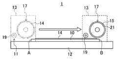
- FIG. 4 is a side view showing the polarizing plate pasting apparatus immediately after the rotating drum in Embodiment 1 has pasted the polarizing plate.
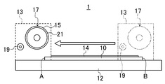
- FIG. 5 is a side view showing the polarizing plate pasting apparatus in which the rotating drum in Embodiment 1 is separated from the liquid crystal display panel.
- FIG. 1 is a perspective view illustrating a schematic configuration of a polarizing plate pasting apparatus according to the first embodiment.
- FIG. 2 is a side view showing a schematic configuration of a polarizing plate sticking apparatus in which the polarizing plate in
- FIG. 6 is a side view showing the polarizing plate pasting apparatus in which the pressing roller in Embodiment 1 is separated from the liquid crystal display panel.
- FIG. 7 is a side view showing the polarizing plate pasting apparatus in which the rotating drum in Embodiment 1 returns to one end side of the liquid crystal display panel.
- FIG. 8 is an enlarged front view showing the vicinity of the end portion of the rotating drum in the second embodiment.
- FIG. 9 is a side view showing a schematic configuration of a polarizing plate sticking apparatus in which the polarizing plate in Embodiment 2 is held by a rotating drum.
- FIG. 10 is a side view showing the polarizing plate pasting apparatus in which the rotating drum in Embodiment 2 is lowered to the use position.
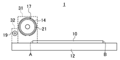
- FIG. 11 is a side view showing the polarizing plate pasting apparatus immediately after the rotating drum in Embodiment 2 has pasted the polarizing plate.
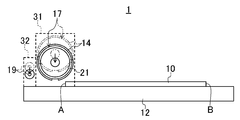
- FIG. 12 is a side view showing the polarizing plate pasting device in which the rotating drum in Embodiment 2 is separated from the liquid crystal display panel.
- FIG. 13 is a side view showing a polarizing plate sticking device in which the pressing roller in Embodiment 2 rolls on the surface of the liquid crystal display panel.
- FIG. 14 is a side view showing the polarizing plate pasting apparatus in which the rotating drum in Embodiment 2 returns to one end side of the liquid crystal display panel.
- FIG. 15 is a side view showing the polarizing plate pasting apparatus in which the pressing roller in Embodiment 2 returns to one end side of the liquid crystal display panel.
- FIG. 16 is a side view showing the polarizing plate sticking apparatus in which the pressing roller in Embodiment 2 is raised on one end side of the liquid crystal display panel.
- FIG. 17 is a side view showing a schematic configuration of the polarizing plate sticking apparatus immediately after the rotating drum in Embodiment 3 attaches the polarizing plate.
- FIG. 18 is a side view showing the polarizing plate pasting device in which the rotating drum in Embodiment 3 is separated from the liquid crystal display panel.
- Embodiment 1 of the Invention 1 to 7 show Embodiment 1 of the present invention.
- FIG. 1 is a perspective view showing a schematic configuration of a polarizing plate sticking apparatus 1 according to the first embodiment.
- FIG. 2 is a side view showing a schematic configuration of the polarizing plate pasting apparatus 1 in which the polarizing plate 14 is held by the rotating drum 17.
- FIG. 3 is a side view showing the polarizing plate pasting apparatus 1 with the rotating drum 17 lowered to the use position.
- FIG. 4 is a side view showing the polarizing plate pasting apparatus 1 immediately after the rotating drum 17 has pasted the polarizing plate.
- FIG. 5 is a side view showing the polarizing plate pasting apparatus 1 in which the rotating drum 17 is separated from the liquid crystal display panel 10.
- FIG. 6 is a side view showing the polarizing plate pasting apparatus 1 in which the pressing roller 19 is separated from the liquid crystal display panel 10.
- FIG. 7 is a side view showing the polarizing plate pasting apparatus 1 in which the rotating drum 17 has returned to the one end A side of the liquid crystal display panel 10.
- the polarizing plate sticking device 1 is a device for sticking the polarizing plate 14 to the liquid crystal display panel 10.
- the polarizing plate pasting apparatus 1 includes a stage 11 that supports the liquid crystal display panel 10, a pair of rail portions 12 that are arranged so as to sandwich the stage 11, and the rail portion 12.
- a pair of frames 13 formed, a rotating drum 17 rotatably supported by the frame 13, and a pressing roller 19 as a restricting member constituted by a roller member are provided.
- the stage 11 has a large number of suction ports (not shown) on its upper surface, and holds the liquid crystal display panel 10 placed by the suction force in the suction ports by vacuum suction.
- suction ports not shown
- the stage 11 in this embodiment has a relatively small suction force at the suction port.
- the rail portions 12 are arranged on both the left and right sides of the stage 11 so as to sandwich the stage 11, and extend parallel to each other.
- Each rail portion 12 is provided with a frame 13 and supports the frame 13 so as to be slidable.
- Each frame 13 is formed in a rectangular plate shape, for example, and is arranged so as to face each other while being supported by the rail portion 12.
- An end portion of the rotating drum 17 and an end portion of the pressing roller 19 are rotatably supported on the frame 13. Further, the rotary drum 17 and the pressing roller 19 are supported by the frame 13 so as to be movable up and down.
- the rotating drum 17 has a rotating surface 15 that holds the polarizing plate 14, as shown in FIGS.
- An adsorbing sheet 21 is provided on the rotating surface 15.
- the suction sheet 21 is made of a flexible resin sheet, and a large number of minute suction cups are formed on the surface thereof. As a result, the suction sheet 21 itself has a relatively weak suction force.
- the rotary drum 17 is used in a retracted position separated from the surface of the stage 11 and the liquid crystal display panel 10 and the lower end thereof approaching to substantially the same height as the surface of the liquid crystal display panel 10. It is supported by the frame 13 so as to be movable up and down between the positions.
- each frame 13 slides on the rail portion 12 synchronously, so that the rotary drum 17 moves to the stage 11.
- the liquid crystal display panel 10 rolls from one end A side to the other end B side on the surface of the supported liquid crystal display panel 10.
- the rotating drum 17 is configured to affix the held polarizing plate 14 on the surface of the liquid crystal display panel 10 by rolling on the surface of the liquid crystal display panel 10 in this way.
- the pressing roller 19 is used in a retracted position separated from the surface of the stage 11 and the liquid crystal display panel 10 and a position where the lower end thereof is slightly lifted from the surface of the liquid crystal display panel 10. It is supported by the frame 13 so as to be movable up and down between the positions.
- the pressing roller 19 is made of a resin such as polyacetal.
- the pressing roller 19 in the present embodiment is supported by the frame 13 that is common to the rotating drum 17, it moves on the liquid crystal display panel 10 simultaneously with the rotating drum 17.
- the pressing roller 19 is configured so as to restrict the movement of the liquid crystal display panel 10 toward the rotary drum 17 so that the liquid crystal display panel 10 does not greatly disengage from the stage 11.
- a first step of supporting the liquid crystal display panel 10 on the stage 11 is performed.
- the liquid crystal display panel 10 is fixed to the stage 11 by vacuum suction.
- the rotating drum 17 and the pressing roller 19 are respectively disposed at the retracted position.
- a second step of holding the polarizing plate 14 on the rotating surface 15 of the rotating drum 17 is performed.
- the large polarizing plate 14 is sucked and held by the suction sheet 21 having the suction force provided on the rotating surface 15 of the rotary drum 17.
- a third step of attaching the polarizing plate 14 to the surface of the liquid crystal display panel 10 is performed. That is, as shown in FIG. 3, on one end A side of the liquid crystal display panel 10, the rotary drum 17 and the pressing roller 19 are respectively lowered from the retracted position to the use position. Subsequently, as shown in FIG. 4, by rotating the frame 13 along the rail portion 12, the rotary drum 17 holding the polarizing plate 14 is moved to the surface of the liquid crystal display panel 10 supported by the stage 11. The liquid crystal display panel 10 is rolled from one end A side to the other end B side. As a result, the polarizing plate 14 is attached to the surface of the liquid crystal display panel 10.
- the pressing roller 19 moves together with the rotating drum 17 from one end A side to the other end B side of the liquid crystal display panel 10 while slightly floating from the surface of the liquid crystal display panel 10.
- the rotating drum 17 to which the polarizing plate 14 is attached is separated from the surface of the liquid crystal display panel 10 on the other end B side of the liquid crystal display panel 10 and is raised to the retracted position.
- the pressing roller 19 is fixed at the use position. That is, since the pressing roller 19 is fixedly disposed on the other end B side of the liquid crystal display panel 10 in a state of being slightly lifted from the surface of the liquid crystal display panel 10, the pressing roller 19 is placed on the surface of the liquid crystal display panel 10. It will be arrange
- the pressing roller 19 is raised from the use position to the retracted position. Thereafter, as shown in FIG. 7, the rotating drum 17 and the pressing roller 19 that are retracted to the retracted position are moved together with the frame 13 from the other end B side to the one end A side of the liquid crystal display panel. Thus, the polarizing plate 14 is attached to the surface of the liquid crystal display panel 10.
- Embodiment 1- Therefore, according to the first embodiment, by rotating the rotating drum 17 holding the polarizing plate 14 from the one end A side to the other end B side on the surface of the liquid crystal display panel 10 supported by the stage 11, A polarizing plate 14 can be attached to the surface of the liquid crystal display panel 10.
- the rotary drum 17 is separated from the surface of the liquid crystal display panel 10 on the other end B side of the liquid crystal display panel 10, the movement of the liquid crystal display panel 10 toward the rotary drum 17 can be restricted by the pressing roller 19. it can. Therefore, unlike the conventional polarizing plate sticking device that vacuum-adsorbs the polarizing plate, it is not necessary to exhaust the rotating drum from the surface of the liquid crystal display panel. Mixing between the display panel 10 and the polarizing plate 14 can be suppressed.
- the rotary drum 17 can be moved to the retracted position while the liquid crystal display panel 10 is sucked and held on the stage 11. . That is, the attaching operation of the polarizing plate 14 can be completed while the liquid crystal display panel 10 is securely supported by the stage 11.
- the adsorption sheet 21 having a relatively weak adsorption force is provided on the surface of the rotary drum 17 and the polarizing plate 14 is attached, even if the polarizing plate is thinned, the polarizing plate has wrinkles. It can be appropriately held without being generated.
- the space for installing the device is greatly increased compared to the case where the rotary drum 17 is retracted sideways. It becomes possible to reduce.
- Embodiment 2 of the Invention >> 8 to 16 show Embodiment 2 of the present invention.
- FIG. 8 is an enlarged front view showing the vicinity of the end of the rotating drum 17 in the second embodiment.
- FIG. 9 is a side view showing a schematic configuration of the polarizing plate pasting apparatus 1 in which the polarizing plate 14 is held by the rotating drum 17.
- FIG. 10 is a side view showing the polarizing plate pasting apparatus 1 with the rotating drum 17 lowered to the use position.
- FIG. 11 is a side view showing the polarizing plate pasting apparatus 1 immediately after the rotating drum 17 has pasted the polarizing plate 14.
- FIG. 12 is a side view showing the polarizing plate pasting apparatus 1 in which the rotating drum 17 is separated from the liquid crystal display panel 10.
- FIG. 13 is a side view showing the polarizing plate pasting apparatus 1 in which the pressing roller 19 rolls on the surface of the liquid crystal display panel 10.
- FIG. 14 is a side view showing the polarizing plate pasting apparatus 1 in which the rotating drum 17 is returned to the one end A side of the liquid crystal display panel 10.
- FIG. 15 is a side view showing the polarizing plate pasting apparatus 1 in which the pressing roller 19 has returned to the one end A side of the liquid crystal display panel 10.
- FIG. 16 is a side view showing the polarizing plate pasting apparatus 1 in which the pressing roller 19 is raised on the one end A side of the liquid crystal display panel 10.
- the polarizing plate pasting apparatus 1 not only provides the pressing roller 19 on the other end B side of the liquid crystal display panel 10, but then removes bubbles from between the polarizing plate 14 and the liquid crystal display panel 10. It is configured.
- the polarizing plate pasting apparatus 1 includes a stage 11 that supports the liquid crystal display panel 10, a pair of rail portions 12 that are arranged so as to sandwich the stage 11, and a first frame 31 that is provided on the rail portion 12. And a second frame 32, a rotary drum 17 rotatably supported by the first frame 31, and a pressing roller 19 rotatably supported by the second frame 32.
- the first and second frames 31 and 32 are each formed in, for example, a rectangular plate shape and supported by the rail portion 12, and the first frames 31 face each other, It arrange
- the second frame 32 is arranged inside the first frame 31, and can slide on the rail portion 12 independently of the first frame 31.
- the rotating drum 17 is supported by the first frame 31 so as to be movable up and down.
- the pressing roller 19 is supported by the second frame 32 so as to be movable up and down.
- the rotary drum 17 is used in a retracted position separated from the surface of the stage 11 and the liquid crystal display panel 10 and the lower end thereof approaching to substantially the same height as the surface of the liquid crystal display panel 10.
- the first frame 31 is supported so as to be movable up and down between the positions.
- the pressing roller 19 approaches the retracted position separated from the surface of the stage 11 and the liquid crystal display panel 10, and the position where the lower end slightly floats from the surface of the liquid crystal display panel 10.
- the frame 13 is supported by the frame 13 so as to be movable up and down. Further, the pressing roller 19 is supported by the frame 13 so as to be movable up and down between a use position and a contact position where the lower end of the press roller 19 is a position where the press roller 19 can contact the surface of the polarizing plate 14 on the liquid crystal display panel 10.
- the pressing roller 19 is disposed on the liquid crystal display panel 10 in a state where the rotary drum 17 is raised on the other end B side of the liquid crystal display panel 10 and separated from the surface of the liquid crystal display panel 10. It is configured to roll on the surface to the other end B side of the liquid crystal display panel 10.
- the pressing roller 19 is made of a resin such as polyacetal.
- the first step of supporting the liquid crystal display panel 10 on the stage 11 is performed.
- the liquid crystal display panel 10 is fixed to the stage 11 by vacuum suction.
- the rotating drum 17 and the pressing roller 19 are respectively disposed at the retracted position.
- a second step of holding the polarizing plate 14 on the rotating surface 15 of the rotating drum 17 is performed.
- the large polarizing plate 14 is sucked and held by the suction sheet 21 having the suction force provided on the rotating surface 15 of the rotary drum 17.
- a third step of attaching the polarizing plate 14 to the surface of the liquid crystal display panel 10 is performed. That is, as shown in FIG. 10, on one end A side of the liquid crystal display panel 10, the rotary drum 17 and the pressing roller 19 are respectively lowered from the retracted position to the use position.
- the rotary drum 17 holding the polarizing plate 14 is supported by the stage 11 by sliding the first and second frames 31 and 32 along the rail portion 12.
- the liquid crystal display panel 10 is rolled from one end A side to the other end B side on the surface of the liquid crystal display panel 10.
- the polarizing plate 14 is attached to the surface of the liquid crystal display panel 10.
- the pressing roller 19 moves from one end A side to the other end B side of the liquid crystal display panel 10 while slightly floating from the surface of the liquid crystal display panel 10.
- the rotating drum 17 to which the polarizing plate 14 is attached is separated from the surface of the liquid crystal display panel 10 on the other end B side of the liquid crystal display panel 10 and is raised to the retracted position. Perform the process.
- the pressing roller 19 is fixed at the use position. That is, since the pressing roller 19 is fixedly disposed on the other end B side of the liquid crystal display panel 10 in a state of being slightly lifted from the surface of the liquid crystal display panel 10, the pressing roller 19 is placed on the surface of the liquid crystal display panel 10. It will be arrange
- a fifth step of removing bubbles from between the polarizing plate 14 and the liquid crystal display panel 10 is performed. That is, as shown in FIG. 13, with the pressing roller 19 lowered from the use position to the contact position, the second frame 32 is moved with the pressing roller 19 in contact with the surface of the polarizing plate 14 on the liquid crystal display panel 10. Further, the liquid crystal display panel 10 is moved to the other end B side.
- the pressing roller 19 moves on the surface of the liquid crystal display panel 10 on the surface of the liquid crystal display panel 10 in a state where the rotary drum 17 rises away from the surface of the liquid crystal display panel 10 on the other end B side of the liquid crystal display panel 10. Roll further to the other end B side. As a result, if bubbles are mixed between the polarizing plate 14 and the liquid crystal display panel 10, the bubbles can be pushed out.
- the rotating drum 17 moving to the retracted position is moved together with the first frame 31 from the other end B side of the liquid crystal display panel 10 to one end A side.
- the press roller 19 is moved from the contact position to the use position and is moved together with the second frame 32 from the other end B side of the liquid crystal display panel 10 to one end A side.
- the pressing roller 19 is moved from the use position to the retracted position.
- the polarizing plate 14 is attached to the surface of the liquid crystal display panel 10.
- the pressing roller 19 is rolled to the other end B side on the surface of the liquid crystal display panel 10 with the rotary drum 17 moved to the retracted position. Bubbles mixed between the liquid crystal display panel 10 can be pushed out to remove the bubbles.
- Embodiment 3 of the Invention >> 17 and 18 show Embodiment 3 of the present invention.
- FIG. 17 is a side view showing a schematic configuration of the polarizing plate attaching apparatus 1 immediately after the rotating drum 17 in Embodiment 3 attaches the polarizing plate.
- FIG. 18 is a side view showing the polarizing plate pasting apparatus 1 in which the rotating drum 17 is separated from the liquid crystal display panel 10.
- the pressing roller 19 which is one restricting member is provided, but the present embodiment 2 is different in that the first restricting member 23 and the second restricting member 25 are provided.
- the polarizing plate sticking apparatus 1 of the present embodiment includes a first pressing roller 23 as a first regulating member disposed on the other end B side of the liquid crystal display panel 10, and the liquid crystal display panel 10. And a second presser roller 25 as a second restricting member disposed in the central portion 24 of the second control member.
- the first pressing roller 23 has the same configuration as that of the first embodiment. Therefore, the first pressing roller 23 is supported by the frame 13 and is configured to be movable up and down between the use position and the retracted position.
- the second pressing roller 25 is supported by a frame (not shown) that is independent from the frame 13, is retracted from the surface of the stage 11 and the liquid crystal display panel 10, and has a lower end at the lower end of the liquid crystal display panel 10. It is configured to be able to move up and down between a use position close to a position slightly floating from the surface.
- first and second pressing rollers 23 and 25 are arranged at the use positions when the rotary drum 17 rises from the use position on the other end B side of the liquid crystal display panel 10.
- the second step of holding the polarizing plate 14 on the rotating surface 15 of 17 is performed.
- the rotary drum 17 and the first pressing roller 23 are moved to the liquid crystal display by moving the frame 13 to the other end B side of the liquid crystal display panel 10 with the second pressing roller 25 raised to the retracted position.
- the liquid crystal display panel 10 is rolled from one end A side to the other end B side on the surface of the panel 10.
- the polarizing plate 14 is attached to the surface of the liquid crystal display panel 10.
- the first pressing roller 23 is disposed on the other end B side of the liquid crystal display panel 10 and the second pressing roller 25 is disposed in the central portion 24 of the liquid crystal display panel 10. That is, as shown in FIG. 17, first, the first pressing roller 23 is fixed at the use position, and the second pressing roller 25 is lowered from the retracted position to the use position. Subsequently, as shown in FIG. 18, the rotary drum 17 is moved away from the surface of the liquid crystal display panel 10 on the other end B side of the liquid crystal display panel 10 and raised to the retracted position.
- the first and second pressing rollers 23 and 25 are raised from the use position to the retracted position, respectively. Thereafter, the rotating drum 17 and the first pressing roller 23 retracted to the retracted position are moved together with the frame 13 from the other end B side to the one end A side of the liquid crystal display panel. Thus, the polarizing plate 14 is attached to the surface of the liquid crystal display panel 10.
- the first and second pressing rollers 23 and 25 for restricting the movement of the liquid crystal display panel 10 toward the rotary drum 17 are provided, so that the liquid crystal is the same as in the first embodiment. Completing the attaching operation of the polarizing plate 14 while the liquid crystal display panel 10 is reliably supported on the stage 11 while suppressing the mixing of dust between the surface of the display panel 10 and the polarizing plate 14. Can do.
- the liquid crystal display panel has been made thinner, and the liquid crystal display panel itself is greatly bent easily. If the liquid crystal display panel is greatly bent, the circuit configuration formed on the liquid crystal display panel may be damaged. In contrast, in the present embodiment, when the rotary drum 17 is raised from the use position, the surface of the liquid crystal display panel 10 can be pressed by the pressing rollers 23 and 25 not only at the other end B side but also at the central portion 24. Therefore, the bending of the liquid crystal display panel 10 can be suppressed, and the liquid crystal display panel 10 can be suitably protected.
- the regulating member is configured by the roller member.
- the regulating member can be configured by a member having another shape.
- the regulating member is configured by a roller member.
- the present invention is not limited thereto, and the outer peripheral portion of the rotating drum is made of a porous elastic body.
- a configuration in which a suction portion is provided may be used, and the polarizing plate may be vacuum-sucked and held on the suction portion.
- the present invention is not limited to the above-described first to third embodiments, and the present invention includes a configuration in which these first to third embodiments are appropriately combined.
- the present invention is useful for a polarizing plate sticking apparatus and a polarizing plate sticking method.
- Polarizer sticking device 10
- Liquid crystal display panel 11 stages 14
- Polarizing plate 15
- Rotating surface 18
- Rotating drum 19
- Pressing roller (regulating member) 21
- Adsorption sheet 23
- First pressing roller (first regulating member) 24
- Second pressing roller second regulating member
Landscapes
- Physics & Mathematics (AREA)
- General Physics & Mathematics (AREA)
- Optics & Photonics (AREA)
- Nonlinear Science (AREA)
- Engineering & Computer Science (AREA)
- Manufacturing & Machinery (AREA)
- Chemical & Material Sciences (AREA)
- Crystallography & Structural Chemistry (AREA)
- Liquid Crystal (AREA)
Abstract
偏光板貼付装置は、液晶表示パネルを支持するステージと、偏光板を保持する回転表面を有し、ステージに支持された液晶表示パネルの表面上で液晶表示パネルの一端側から他端側へ転動することにより、保持していた偏光板を液晶表示パネルの表面に貼り付ける回転ドラムと、その他端側において回転ドラムが液晶表示パネルの表面から離隔する際に、液晶表示パネルの回転ドラム側への移動を規制する規制部材とを備えている。
Description
本発明は、偏光板貼付装置及び偏光板貼付方法に関するものである。
液晶表示装置は、複数のTFT(薄膜トランジスタ)が形成されたTFT基板と、TFT基板に対向して配置された対向基板と、これらTFT基板及び対向基板の間に封入された液晶層とを有する液晶表示パネルを備えている。TFT基板及び対向基板には、それぞれ液晶層と反対側の表面に偏光板が貼り付けられている。
特許文献1には、偏光板を液晶表示パネルに貼り付ける偏光板貼付装置が開示されている。この偏光板貼付装置は、偏光板を搬送する偏光板搬送部と、この偏光板搬送部から受け取った偏光板を回転表面で真空吸着する回転ドラムと、液晶表示パネルを吸着固定して搬送するステージとを備えている。
上記回転ドラムは、ドラム本体と、ドラム本体の外周部分に設けられた多孔質の弾性体からなる吸着部とを有している。一方、偏光板は、粘着面と非粘着面とを有している。そして、その偏光板の非粘着面が、ドラム本体の吸引力によって上記回転ドラムの吸着部に吸着保持されるようになっている。
そして、上記偏光板貼付装置は、回転ドラムの下方の偏光板貼り付け位置において、回転ドラムによって搬送された偏光板を、ステージに吸着固定されている液晶表示パネルに粘着させて貼り付けるように構成されている。
上記特許文献1の偏光板貼付装置では、1つの回転ドラムに複数の偏光板を同時に吸着して、複数の液晶表示パネルに連続的に当該偏光板を貼り付けるように構成されているが、近年、液晶表示パネルが大型化されていることから、1つの回転ドラムに大きい偏光板を1枚ずつ吸着させて液晶表示パネルに貼り付けていくことが必要となっている。
この場合、回転ドラムが液晶表示パネルの表面上をその一端側から他端側へ転動しながら、その偏光板を徐々に液晶表示パネルの表面に貼り付けていく。そして、回転ドラムが液晶表示パネルの他端側に到達したときに、ドラム本体の吸気が排気に切り替えられた状態で、当該回転ドラムが偏光板から離隔される。こうして、偏光板が液晶表示パネルに貼り付けられることとなる。
しかし、上記従来の偏光板貼付装置では、回転ドラムを偏光板から離隔させる際にその吸着部から排気を行うようになっているので、その排気によって周囲の粉塵が舞上げられる虞がある。その結果、液晶表示パネルの表面と偏光板との間に粉塵が混入し得る問題がある。
一方、本発明者は、偏光板を吸引して保持するための多孔質の吸着部に代えて、吸着力が比較的弱い吸着シートを回転ドラムの表面に設けて偏光板の貼り付けを行うことを検討している。近年、偏光板の薄型化が進められているところ、薄型化された偏光板を真空吸着すると、当該偏光板に皺が生じるために回転ドラムによる適切な保持が難しい。これに対し、上記吸着シートを用いれば、皺を生じさせることなく偏光板を回転ドラムに保持させることが可能になる。
ところが、上記吸着シートを有する回転ドラムによって偏光板を液晶表示パネルに貼り付ける場合、偏光板を貼り終わった回転ドラムが液晶表示パネルの端部を吸着してしまう問題がある。その結果、上方位置に退避する回転ドラムによって液晶表示パネルの端部が持ち上げられ、液晶表示パネルがステージから外れて損傷する虞がある。
本発明は、斯かる点に鑑みてなされたものであり、その目的とするところは、液晶表示パネルの表面と偏光板との間への粉塵の混入を抑制しながらも、液晶表示パネルをステージに確実に支持させた状態で偏光板の貼り付け作業を完了させることにある。
上記の目的を達成するために、本発明に係る偏光板貼付装置は、液晶表示パネルを支持するステージと、偏光板を保持する回転表面を有し、上記ステージに支持された液晶表示パネルの表面上で該液晶表示パネルの一端側から他端側へ転動することにより、保持していた上記偏光板を上記液晶表示パネルの表面に貼り付ける回転ドラムと、上記回転ドラムが上記液晶表示パネルの他端側において該液晶表示パネルの表面から離隔する際に、上記液晶表示パネルの上記回転ドラム側への移動を規制する規制部材とを備えている。
また、本発明に係る偏光板貼り付け方法は、液晶表示パネルをステージに支持させる第1工程と、回転ドラムの回転表面に偏光板を保持させる第2工程と、上記偏光板を保持した回転ドラムを、上記ステージに支持された液晶表示パネルの表面上で該液晶表示パネルの一端側から他端側へ転動させることにより、上記偏光板を上記液晶表示パネルの表面に貼り付ける第3工程と、上記偏光板を貼り付けた上記回転ドラムを、上記液晶表示パネルの他端側において該液晶表示パネルの表面から離隔させる第4工程とを有している。
そして、上記第4工程では、上記液晶表示パネルの上記回転ドラム側への移動を規制部材によって規制する。
本発明によれば、偏光板を保持した回転ドラムを、ステージに支持された液晶表示パネルの表面上でその一端側から他端側へ転動させることより、その液晶表示パネルの表面に偏光板を貼り付けるようにした偏光板貼付装置について、回転ドラムが液晶表示パネルの他端側においてその液晶表示パネルの表面から離隔する際に、その液晶表示パネルの回転ドラム側への移動を規制部材によって規制するようにしたので、回転ドラムからの排気等を不要にして液晶表示パネルの表面と偏光板との間への粉塵の混入を抑制しながらも、その液晶表示パネルをステージに確実に支持させた状態で偏光板の貼り付け作業を完了させることができる。
以下、本発明の実施形態を図面に基づいて詳細に説明する。尚、本発明は、以下の実施形態に限定されるものではない。
《発明の実施形態1》
図1~図7は、本発明の実施形態1を示している。
図1~図7は、本発明の実施形態1を示している。
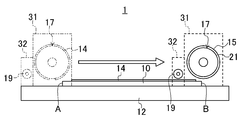
図1は、本実施形態1における偏光板貼付装置1の概略構成を示す斜視図である。図2は、偏光板14が回転ドラム17によって保持された偏光板貼付装置1の概略構成を示す側面図である。図3は、回転ドラム17が使用位置に下降した偏光板貼付装置1を示す側面図である。図4は、回転ドラム17が偏光板を貼り付けた直後の偏光板貼付装置1を示す側面図である。
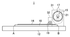
また、図5は、回転ドラム17が液晶表示パネル10から離隔した偏光板貼付装置1を示す側面図である。図6は、押さえローラ19が液晶表示パネル10から離隔した偏光板貼付装置1を示す側面図である。図7は、回転ドラム17が液晶表示パネル10の一端A側に戻った偏光板貼付装置1を示す側面図である。
偏光板貼付装置1は、偏光板14を液晶表示パネル10に貼り付けるための装置である。図1及び図2に示すように、偏光板貼付装置1は、液晶表示パネル10を支持するステージ11と、ステージ11を挟むように配置された一対のレール部12と、このレール部12に設けられた一対のフレーム13と、このフレーム13に回転可能に支持された回転ドラム17と、ローラ部材によって構成された規制部材としての押さえローラ19とを備えている。
ステージ11は、その上面に多数の吸着口(図示省略)を有し、その吸着口における吸引力によって載置された液晶表示パネル10を真空吸着して保持するようになっている。ここで、比較的大型の液晶表示パネルをステージ11に真空吸着させる場合、吸着口における吸引力が大きいと、液晶表示パネル10の液晶がその吸引力によって吸着口近傍に集まりやすくなるため、液晶分布にムラが生じる問題がある。したがって、本実施形態におけるステージ11は、吸着口における吸引力が比較的小さくなっている。
レール部12は、図1に示すように、ステージ11を挟むようにステージ11の左右両側にそれぞれ配置され、互いに平行に延びている。各レール部12には、フレーム13がそれぞれ装着されており、このフレーム13をスライド移動可能に支持している。
各フレーム13は、それぞれ例えば矩形板状に形成され、レール部12に支持された状態で互いに対向するように配置されている。このフレーム13には、回転ドラム17の端部と、押さえローラ19の端部とがそれぞれ回転可能に軸支されている。さらに、回転ドラム17及び押さえローラ19は、それぞれフレーム13に昇降可能に支持されている。
回転ドラム17は、図1、図2及び図4に示すように、偏光板14を保持する回転表面15を有している。この回転表面15には、吸着シート21が設けられている。吸着シート21は、可撓性を有する樹脂シートからなり、その表面に微小な吸盤が多数形成されている。そのことにより、吸着シート21自体が比較的弱い吸着力を有している。
また、回転ドラム17は、図2~図5に示すように、ステージ11及び液晶表示パネル10の表面から離隔した退避位置と、その下端が液晶表示パネル10の表面と略同じ高さまで接近した使用位置との間で昇降可能にフレーム13に支持されている。
そして、図2~図4に示すように、回転ドラム17が使用位置に移動した状態で、各フレーム13が同期してレール部12上をスライド移動することにより、この回転ドラム17がステージ11に支持された液晶表示パネル10の表面上で液晶表示パネル10の一端A側から他端B側へ転動するようになっている。そうして、回転ドラム17は、このように液晶表示パネル10の表面上を転動することによって、保持していた偏光板14を液晶表示パネル10の表面に貼り付けるように構成されている。
押さえローラ19は、図3及び図6に示すように、ステージ11及び液晶表示パネル10の表面から離隔した退避位置と、その下端が液晶表示パネル10の表面から僅かに浮いた位置まで接近した使用位置との間で昇降可能にフレーム13に支持されている。押さえローラ19は、例えばポリアセタール等の樹脂によって構成されている。
本実施形態における押さえローラ19は、回転ドラム17と共通のフレーム13に支持されているため、回転ドラム17と同時に液晶表示パネル10上を移動するようになっている。
そして、図5に示すように、使用位置の回転ドラム17が液晶表示パネル10の他端B側において液晶表示パネル10の表面から離隔する際に、この液晶表示パネル10の他端B側において、押さえローラ19が液晶表示パネル10の表面近傍の使用位置に留まっている。そのことにより、押さえローラ19は、液晶表示パネル10の回転ドラム17側への移動を規制して、その液晶表示パネル10がステージ11から大きく外れないように構成されている。
-貼付方法-
次に、上記偏光板貼付装置1による偏光板貼付方法ついて説明する。
次に、上記偏光板貼付装置1による偏光板貼付方法ついて説明する。
まず、図1及び図2に示すように、液晶表示パネル10をステージ11に支持させる第1工程を行う。このとき、液晶表示パネル10をステージ11に真空吸着させて固定する。また、図2に示すように、回転ドラム17及び押さえローラ19は、それぞれ退避位置に配置されている。
次に、図2に示すように、回転ドラム17の回転表面15に偏光板14を保持させる第2工程を行う。この第2工程では、回転ドラム17の回転表面15に設けた吸着力を有する吸着シート21によって、大判の偏光板14を吸着保持させる。
次に、偏光板14を液晶表示パネル10の表面に貼り付ける第3工程を行う。すなわち、図3に示すように、液晶表示パネル10の一端A側において、回転ドラム17及び押さえローラ19を、それぞれ退避位置から使用位置へ下降させる。続いて、図4に示すように、フレーム13をレール部12に沿ってスライド移動させることにより、偏光板14を保持している回転ドラム17を、ステージ11に支持された液晶表示パネル10の表面上で液晶表示パネル10の一端A側から他端B側へ転動させる。そのことにより、偏光板14を液晶表示パネル10の表面に貼り付ける。
このとき、押さえローラ19は、液晶表示パネル10の表面から僅かに浮いた状態で、回転ドラム17と共に液晶表示パネル10の一端A側から他端B側へ移動する。
次に、図5に示すように、偏光板14を貼り付けた回転ドラム17を、液晶表示パネル10の他端B側において液晶表示パネル10の表面から離隔させて、退避位置に上昇させる第4工程を行う。この工程では、押さえローラ19を使用位置に固定しておく。すなわち、押さえローラ19は、液晶表示パネル10の他端B側において、この液晶表示パネル10の表面から僅かに浮いた状態で固定配置されることから、液晶表示パネル10の表面に押さえローラ19を当接可能に配置されることとなる。
したがって、回転ドラム17が使用位置から上昇する際に、その吸着シート21の吸着力によって液晶表示パネル10の他端Bが引き上げられると、すぐに液晶表示パネル10の表面が押さえローラ19に当接するため、この押さえローラ19によって液晶表示パネル10の回転ドラム17側への移動が規制される。そして、吸着シート21から離脱した液晶表示パネル10は、再びステージ11の表面に保持されることとなる。
次に、図6に示すように、液晶表示パネル10の他端B側において、押さえローラ19を使用位置から退避位置へ上昇させる。その後、図7に示すように、それぞれ退避位置に退避している回転ドラム17及び押さえローラ19を、フレーム13と共に液晶表示パネルの他端B側から一端A側へ移動させる。こうして、液晶表示パネル10の表面に偏光板14を貼り付ける。
-実施形態1の効果-
したがって、この実施形態1によると、偏光板14を保持した回転ドラム17を、ステージ11に支持された液晶表示パネル10の表面上でその一端A側から他端B側へ転動させることより、その液晶表示パネル10の表面に偏光板14を貼り付けることができる。そして、回転ドラム17が液晶表示パネル10の他端B側においてその液晶表示パネル10の表面から離隔する際に、押さえローラ19によって液晶表示パネル10の回転ドラム17側への移動を規制することができる。したがって、従来の偏光板を真空吸着する偏光板貼付装置のように、回転ドラムを液晶表示パネルの表面から離脱させる際に当該回転ドラムから排気を行う必要がないので、排気により舞い上がった粉塵の液晶表示パネル10と偏光板14との間への混入を抑制できる。
したがって、この実施形態1によると、偏光板14を保持した回転ドラム17を、ステージ11に支持された液晶表示パネル10の表面上でその一端A側から他端B側へ転動させることより、その液晶表示パネル10の表面に偏光板14を貼り付けることができる。そして、回転ドラム17が液晶表示パネル10の他端B側においてその液晶表示パネル10の表面から離隔する際に、押さえローラ19によって液晶表示パネル10の回転ドラム17側への移動を規制することができる。したがって、従来の偏光板を真空吸着する偏光板貼付装置のように、回転ドラムを液晶表示パネルの表面から離脱させる際に当該回転ドラムから排気を行う必要がないので、排気により舞い上がった粉塵の液晶表示パネル10と偏光板14との間への混入を抑制できる。
しかも、液晶表示パネル10の回転ドラム17側への移動を押さえローラ19によって規制したので、液晶表示パネル10をステージ11に吸着保持させた状態で、回転ドラム17を退避位置へ移動させることができる。すなわち、液晶表示パネル10をステージ11に確実に支持させた状態で偏光板14の貼り付け作業を完了させることができる。
また、吸着力が比較的弱い吸着シート21を回転ドラム17の表面に設けて偏光板14の貼り付けを行うようにしたので、薄型化された偏光板であっても、当該偏光板に皺が生じないようにして適切に保持することができる。
また、液晶表示パネル10の他端B側において、回転ドラム17を上昇させて退避させるようにしたので、回転ドラム17を側方に退避させるような場合に比べて装置を設置するスペースを大幅に縮小することが可能になる。
《発明の実施形態2》
図8~図16は、本発明の実施形態2を示している。
図8~図16は、本発明の実施形態2を示している。
図8は、本実施形態2における回転ドラム17端部の近傍部分を拡大して示す正面図である。図9は、偏光板14が回転ドラム17によって保持された偏光板貼付装置1の概略構成を示す側面図である。図10は、回転ドラム17が使用位置に下降した偏光板貼付装置1を示す側面図である。
図11は、回転ドラム17が偏光板14を貼り付けた直後の偏光板貼付装置1を示す側面図である。図12は、回転ドラム17が液晶表示パネル10から離隔した偏光板貼付装置1を示す側面図である。図13は、押さえローラ19が液晶表示パネル10の表面を転動する偏光板貼付装置1を示す側面図である。
図14は、回転ドラム17が液晶表示パネル10の一端A側に戻った偏光板貼付装置1を示す側面図である。図15は、押さえローラ19が液晶表示パネル10の一端A側に戻った偏光板貼付装置1を示す側面図である。図16は、押さえローラ19が液晶表示パネル10の一端A側で上昇した偏光板貼付装置1を示す側面図である。
尚、以降の各実施形態では、図1~図7と同じ部分については同じ符号を付して、その詳細な説明を省略する。
本実施形態2における偏光板貼付装置1は、押さえローラ19を液晶表示パネル10の他端B側に設けるだけでなく、その後に偏光板14と液晶表示パネル10との間から気泡を除去するように構成されている。
本実施形態における偏光板貼付装置1は、液晶表示パネル10を支持するステージ11と、ステージ11を挟むように配置された一対のレール部12と、このレール部12に設けられた第1フレーム31及び第2フレーム32と、第1フレーム31に回転可能に支持された回転ドラム17と、第2フレーム32に回転可能に支持された押さえローラ19とを備えている。
図8及び図9に示すように、第1及び第2フレーム31,32は、それぞれ例えば矩形板状に形成され、レール部12に支持された状態で、第1フレーム31同士が対向すると共に、第2フレーム同士が対向するように配置されている。
図8に示すように、第2フレーム32は、第1フレーム31の内側に配置されており、第1フレーム31とは独立してレール部12上をスライド移動できるようになっている。また、回転ドラム17は、第1フレーム31に昇降可能に支持されている。一方、押さえローラ19は、第2フレーム32に昇降可能に支持されている。
すなわち、回転ドラム17は、図9~図12に示すように、ステージ11及び液晶表示パネル10の表面から離隔した退避位置と、その下端が液晶表示パネル10の表面と略同じ高さまで接近した使用位置との間で昇降可能に第1フレーム31に支持されている。
一方、押さえローラ19は、図10及び図16に示すように、ステージ11及び液晶表示パネル10の表面から離隔した退避位置と、その下端が液晶表示パネル10の表面から僅かに浮いた位置まで接近した使用位置との間で昇降可能にフレーム13に支持されている。さらに、押さえローラ19は、使用位置と、その下端が液晶表示パネル10上の偏光板14表面に接触可能な位置である接触位置との間で昇降可能にフレーム13に支持されている。
そうして、押さえローラ19は、図13に示すように、回転ドラム17が液晶表示パネル10の他端B側で上昇して液晶表示パネル10の表面から離隔した状態で、液晶表示パネル10の表面上を液晶表示パネル10の他端B側へ転動するように構成されている。押さえローラ19は、例えばポリアセタール等の樹脂によって構成されている。
-貼付方法-
次に、上記偏光板貼付装置1による偏光板貼付方法ついて説明する。
次に、上記偏光板貼付装置1による偏光板貼付方法ついて説明する。
まず、図9に示すように、液晶表示パネル10をステージ11に支持させる第1工程を行う。このとき、液晶表示パネル10をステージ11に真空吸着させて固定する。また、図2に示すように、回転ドラム17及び押さえローラ19は、それぞれ退避位置に配置されている。
次に、図9に示すように、回転ドラム17の回転表面15に偏光板14を保持させる第2工程を行う。この第2工程では、回転ドラム17の回転表面15に設けた吸着力を有する吸着シート21によって、大判の偏光板14を吸着保持させる。
次に、偏光板14を液晶表示パネル10の表面に貼り付ける第3工程を行う。すなわち、図10に示すように、液晶表示パネル10の一端A側において、回転ドラム17及び押さえローラ19を、それぞれ退避位置から使用位置へ下降させる。
続いて、図11に示すように、第1及び第2フレーム31,32をレール部12に沿ってスライド移動させることにより、偏光板14を保持している回転ドラム17を、ステージ11に支持された液晶表示パネル10の表面上で液晶表示パネル10の一端A側から他端B側へ転動させる。そのことにより、偏光板14を液晶表示パネル10の表面に貼り付ける。このとき、押さえローラ19は、液晶表示パネル10の表面から僅かに浮いた状態で、液晶表示パネル10の一端A側から他端B側へ移動する。
次に、図12に示すように、偏光板14を貼り付けた回転ドラム17を、液晶表示パネル10の他端B側において液晶表示パネル10の表面から離隔させて、退避位置に上昇させる第4工程を行う。この工程では、押さえローラ19を使用位置に固定しておく。すなわち、押さえローラ19は、液晶表示パネル10の他端B側において、この液晶表示パネル10の表面から僅かに浮いた状態で固定配置されることから、液晶表示パネル10の表面に押さえローラ19を当接可能に配置されることとなる。
したがって、回転ドラム17が使用位置から上昇する際に、その吸着シート21の吸着力によって液晶表示パネル10の他端Bが引き上げられると、すぐに液晶表示パネル10の表面が押さえローラ19に当接するため、この押さえローラ19によって液晶表示パネル10の移動が規制される。そして、吸着シート21から離脱した液晶表示パネル10は、再びステージ11の表面に保持されることとなる。
次に、偏光板14と液晶表示パネル10との間から気泡を除去する第5工程を行う。すなわち、図13に示すように、押さえローラ19を使用位置から接触位置まで下降させて、この押さえローラ19を液晶表示パネル10上の偏光板14表面に接触させた状態で、第2フレーム32をさらに液晶表示パネル10の他端B側へ移動させる。
そのことにより、回転ドラム17が液晶表示パネル10の他端B側において液晶表示パネル10の表面から上昇して離隔した状態で、押さえローラ19が液晶表示パネル10の表面上で液晶表示パネル10の他端B側へさらに転動する。このことによって、偏光板14と液晶表示パネル10との間に気泡が混入していれば、その気泡を外部へ押し出すことが可能となる。
次に、図14に示すように、退避位置に移動している回転ドラム17を、第1フレーム31と共に液晶表示パネル10の他端B側から一端A側へ移動させる。次に、図15に示すように、押さえローラ19を接触位置から使用位置に上昇させた状態で、第2フレーム32と共に液晶表示パネル10の他端B側から一端A側へ移動させる。その後、図16に示すように、この液晶表示パネル10の一端A側において、押さえローラ19を使用位置から退避位置へ移動させる。こうして、液晶表示パネル10の表面に偏光板14を貼り付ける。
-実施形態2の効果-
したがって、この実施形態2によっても、液晶表示パネル10の回転ドラム17側への移動を規制する押さえローラ19を設けるようにしたので、上記実施形態1と同様に、液晶表示パネル10の表面と偏光板14との間への粉塵の混入を抑制しながらも、その液晶表示パネル10をステージ11に確実に支持させた状態で偏光板14の貼り付け作業を完了させることができる。
したがって、この実施形態2によっても、液晶表示パネル10の回転ドラム17側への移動を規制する押さえローラ19を設けるようにしたので、上記実施形態1と同様に、液晶表示パネル10の表面と偏光板14との間への粉塵の混入を抑制しながらも、その液晶表示パネル10をステージ11に確実に支持させた状態で偏光板14の貼り付け作業を完了させることができる。
ところで、偏光板14を回転ドラム17によって貼り付けると、その偏光板14の貼り終わり部分(つまり液晶表示パネル10の他端B側部分)には、液晶表示パネル10との間に気泡が比較的混入しやすい。これに対し、本実施形態では、回転ドラム17が退避位置に移動した状態で、押さえローラ19を液晶表示パネル10の表面上でその他端B側へ転動させるようにしたので、偏光板14と液晶表示パネル10との間に混入している気泡を外部へ押し出して、当該気泡を除去することができる。
《発明の実施形態3》
図17及び図18は、本発明の実施形態3を示している。
図17及び図18は、本発明の実施形態3を示している。
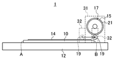
図17は、本実施形態3における回転ドラム17が偏光板を貼り付けた直後の偏光板貼付装置1の概略構成を示す側面図である。図18は、回転ドラム17が液晶表示パネル10から離隔した偏光板貼付装置1を示す側面図である。
上記実施形態1では、1つの規制部材である押さえローラ19を設けたのに対し、本実施形態2は、第1規制部材23及び第2規制部材25を設けた点で相違している。
すなわち、本実施形態の偏光板貼付装置1は、図17に示すように、液晶表示パネル10の他端B側に配置される第1規制部材としての第1押さえローラ23と、液晶表示パネル10の中央部24に配置される第2規制部材としての第2押さえローラ25とを有している。
第1押さえローラ23は、上記実施形態1と同様の構成を有している。したがって、第1押さえローラ23は、フレーム13に支持されると共に、使用位置と退避位置との間で昇降可能に構成されている。
一方、第2押さえローラ25は、フレーム13とは別個独立した図示省略のフレームに支持されると共に、ステージ11及び液晶表示パネル10の表面から離隔した退避位置と、その下端が液晶表示パネル10の表面から僅かに浮いた位置まで接近した使用位置との間で昇降可能に構成されている。
そうして、第1及び第2押さえローラ23,25は、回転ドラム17が液晶表示パネル10の他端B側において使用位置から上昇する際に、それぞれ使用位置に配置させるようになっている。
本実施形態における偏光板貼付装置1によって偏光板14を液晶表示パネル10に貼り付ける場合には、上記実施形態1と同様に、液晶表示パネル10をステージ11に支持させる第1工程と、回転ドラム17の回転表面15に偏光板14を保持させる第2工程とを行う。
第3工程では、第2押さえローラ25を退避位置に上昇させた状態で、フレーム13を液晶表示パネル10の他端B側へ移動させることにより、回転ドラム17及び第1押さえローラ23を液晶表示パネル10の表面上で液晶表示パネル10の一端A側から他端B側へ転動させる。そのことにより、偏光板14を液晶表示パネル10の表面に貼り付ける。
次に、第4工程では、液晶表示パネル10の他端B側に第1押さえローラ23を配置させると共に、液晶表示パネル10の中央部24に第2押さえローラ25を配置させる。すなわち、図17に示すように、まず、第1押さえローラ23を使用位置に固定しておくと共に、第2押さえローラ25を退避位置から使用位置に降下させる。続いて、図18に示すように、回転ドラム17を、液晶表示パネル10の他端B側において液晶表示パネル10の表面から離隔させて、退避位置に上昇させる。
したがって、回転ドラム17が使用位置から上昇する際に、その吸着シート21の吸着力によって液晶表示パネル10の他端Bが引き上げられると、すぐに液晶表示パネル10の表面が第1及び第2押さえローラ23,25に当接するため、この第1及び第2押さえローラ23,25によって液晶表示パネル10の回転ドラム17側への移動が規制される。そして、吸着シート21から離脱した液晶表示パネル10は、再びステージ11の表面に保持される。
次に、第1及び第2押さえローラ23,25をそれぞれ使用位置から退避位置へ上昇させる。その後、それぞれ退避位置に退避している回転ドラム17及び第1押さえローラ23を、フレーム13と共に液晶表示パネルの他端B側から一端A側へ移動させる。こうして、液晶表示パネル10の表面に偏光板14を貼り付ける。
-実施形態3の効果-
したがって、この実施形態3によっても、液晶表示パネル10の回転ドラム17側への移動を規制する第1及び第2押さえローラ23,25を設けるようにしたので、上記実施形態1と同様に、液晶表示パネル10の表面と偏光板14との間への粉塵の混入を抑制しながらも、その液晶表示パネル10をステージ11に確実に支持させた状態で偏光板14の貼り付け作業を完了させることができる。
したがって、この実施形態3によっても、液晶表示パネル10の回転ドラム17側への移動を規制する第1及び第2押さえローラ23,25を設けるようにしたので、上記実施形態1と同様に、液晶表示パネル10の表面と偏光板14との間への粉塵の混入を抑制しながらも、その液晶表示パネル10をステージ11に確実に支持させた状態で偏光板14の貼り付け作業を完了させることができる。
ところで、近年、液晶表示パネルの薄型化が進められており、液晶表示パネル自体が大きく撓みやすくなっている。液晶表示パネルが大きく撓むと、この液晶表示パネルに形成されている回路構成が損傷する虞がある。これに対し、本実施形態では、回転ドラム17を使用位置から上昇させる際に、液晶表示パネル10の表面を他端B側だけでなく中央部24においても押さえローラ23,25によって押さえることが可能であるため、液晶表示パネル10の撓みを抑制でき、液晶表示パネル10を好適に保護することができる。
《その他の実施形態》
上記各実施形態では、規制部材をローラ部材によって構成した例について説明したが、その他の形状の部材によって規制部材を構成することが可能である。しかしながら、上記実施形態2のように偏光板14の表面を転動させて気泡を抜くような場合には、ローラ部材によって規制部材を構成することが好ましい。
上記各実施形態では、規制部材をローラ部材によって構成した例について説明したが、その他の形状の部材によって規制部材を構成することが可能である。しかしながら、上記実施形態2のように偏光板14の表面を転動させて気泡を抜くような場合には、ローラ部材によって規制部材を構成することが好ましい。
また、上記各実施形態では、回転ドラム17が吸着シート21によって偏光板14を吸着保持する例について説明したが、本発明はこれに限らず、回転ドラムの外周部分に多孔質の弾性体からなる吸着部を設けた構成とし、偏光板を吸着部に真空吸着させて保持するようにしてもよい。
また、本発明は上記実施形態1~3に限定されるものでなく、本発明には、これらの実施形態1~3を適宜組み合わせた構成が含まれる。
以上説明したように、本発明は、偏光板貼付装置及び偏光板貼付方法について有用である。
1 偏光板貼付装置
10 液晶表示パネル
11 ステージ
14 偏光板
15 回転表面
17 回転ドラム
19 押さえローラ(規制部材)
21 吸着シート
23 第1押さえローラ(第1規制部材)
24 中央部
25 第2押さえローラ(第2規制部材)
10 液晶表示パネル
11 ステージ
14 偏光板
15 回転表面
17 回転ドラム
19 押さえローラ(規制部材)
21 吸着シート
23 第1押さえローラ(第1規制部材)
24 中央部
25 第2押さえローラ(第2規制部材)
Claims (12)
- 液晶表示パネルを支持するステージと、
偏光板を保持する回転表面を有し、上記ステージに支持された液晶表示パネルの表面上で該液晶表示パネルの一端側から他端側へ転動することにより、保持していた上記偏光板を上記液晶表示パネルの表面に貼り付ける回転ドラムと、
上記回転ドラムが上記液晶表示パネルの他端側において該液晶表示パネルの表面から離隔する際に、上記液晶表示パネルの上記回転ドラム側への移動を規制する規制部材とを備えている
ことを特徴とする偏光板貼付装置。 - 請求項1に記載された偏光板貼付装置において、
上記ステージを挟むように配置されたレール部と、
上記レール部にスライド移動可能に支持されると共に、上記回転ドラムを回転可能に且つ昇降可能に支持するフレームとをさらに備え、
上記規制部材は、上記フレームに支持されている
ことを特徴とする偏光板貼付装置。 - 請求項1に記載された偏光板貼付装置において、
上記ステージを挟むように配置されたレール部と、
上記レール部にスライド移動可能に支持されると共に、上記回転ドラムを回転可能に且つ昇降可能に支持する第1フレームと、
上記レール部に上記第1フレームとは独立してスライド移動可能に支持されると共に、上記規制部材を回転可能に且つ昇降可能に支持する第2フレームとをさらに備えている
ことを特徴とする偏光板貼付装置。 - 請求項3に記載された偏光板貼付装置において、
上記規制部材は、上記回転ドラムが上記液晶表示パネルの他端側で上昇して該液晶表示パネルの表面から離隔した状態で、上記液晶表示パネルの表面上を上記他端側へ転動するように構成されている
ことを特徴とする偏光板貼付装置。 - 請求項1乃至4の何れか1つに記載された偏光板貼付装置において、
上記回転ドラムの回転表面には、吸着力を有する吸着シートが設けられている
ことを特徴とする偏光板貼付装置。 - 請求項1乃至5の何れか1つに記載された偏光板貼付装置において、
上記規制部材はローラ部材によって構成され、
上記ローラ部材は、上記回転ドラムが上記液晶表示パネルの他端側において該液晶表示パネルの表面から離隔した状態で、上記液晶表示パネルの表面上を該液晶表示パネルの他端側へ転動するように構成されている
ことを特徴とする偏光板貼付装置。 - 請求項1乃至6の何れか1つに記載された偏光板貼付装置において、
上記規制部材は、上記液晶表示パネルの他端側に配置される第1規制部材と、上記液晶表示パネルの中央部に配置される第2規制部材とを有している
ことを特徴とする偏光板貼付装置。 - 液晶表示パネルをステージに支持させる第1工程と、
回転ドラムの回転表面に偏光板を保持させる第2工程と、
上記偏光板を保持した回転ドラムを、上記ステージに支持された液晶表示パネルの表面上で該液晶表示パネルの一端側から他端側へ転動させることにより、上記偏光板を上記液晶表示パネルの表面に貼り付ける第3工程と、
上記偏光板を貼り付けた上記回転ドラムを、上記液晶表示パネルの他端側で上昇させて該液晶表示パネルの表面から離隔させる第4工程とを有し、
上記第4工程では、上記液晶表示パネルの上記回転ドラム側への移動を規制部材によって規制する
ことを特徴とする偏光板貼付方法。 - 請求項8に記載された偏光板貼付方法において、
上記第4工程の後に、上記回転ドラムが上記液晶表示パネルの他端側で上昇して該液晶表示パネルの表面から離隔した状態で、上記規制部材を上記液晶表示パネルの表面上を上記他端側へ転動させる第5工程を行う
ことを特徴とする偏光板貼付方法。 - 請求項8又は9に記載された偏光板貼付方法において、
上記第2工程では、上記回転ドラムの回転表面に設けた吸着力を有する吸着シートによって、上記偏光板を吸着保持させる
ことを特徴とする偏光板貼付方法。 - 請求項8乃至10の何れか1つに記載された偏光板貼付方法において、
上記第4工程の後に、上記回転ドラムが上記液晶表示パネルの他端側において該液晶表示パネルの表面から離隔した状態で、ローラ部材によって構成された上記規制部材を、上記液晶表示パネルの表面上で該液晶表示パネルの他端側へ転動させる第5工程を行う
ことを特徴とする偏光板貼付方法。 - 請求項8乃至11の何れか1つに記載された偏光板貼付方法において、
上記第4工程では、上記液晶表示パネルの他端側に第1規制部材を配置させると共に、上記液晶表示パネルの中央部に第2規制部材を配置させる
ことを特徴とする偏光板貼付方法。
Applications Claiming Priority (2)
| Application Number | Priority Date | Filing Date | Title |
|---|---|---|---|
| JP2011-091978 | 2011-04-18 | ||
| JP2011091978 | 2011-04-18 |
Publications (1)
| Publication Number | Publication Date |
|---|---|
| WO2012144169A1 true WO2012144169A1 (ja) | 2012-10-26 |
Family
ID=47041303
Family Applications (1)
| Application Number | Title | Priority Date | Filing Date |
|---|---|---|---|
| PCT/JP2012/002541 Ceased WO2012144169A1 (ja) | 2011-04-18 | 2012-04-12 | 偏光板貼付装置及び偏光板貼付方法 |
Country Status (1)
| Country | Link |
|---|---|
| WO (1) | WO2012144169A1 (ja) |
Cited By (1)
| Publication number | Priority date | Publication date | Assignee | Title |
|---|---|---|---|---|
| CN107817619A (zh) * | 2017-11-17 | 2018-03-20 | 武汉华星光电技术有限公司 | 一种偏光片贴附设备及系统 |
Citations (5)
| Publication number | Priority date | Publication date | Assignee | Title |
|---|---|---|---|---|
| JP2003005666A (ja) * | 2001-06-21 | 2003-01-08 | Toyota Industries Corp | 貼り付け装置及び貼り付け方法 |
| JP2003161935A (ja) * | 2001-11-27 | 2003-06-06 | Sharp Corp | 偏光板貼付装置 |
| JP2009186497A (ja) * | 2008-02-01 | 2009-08-20 | Sharp Corp | 液晶表示パネルの製造装置および液晶表示パネルの製造方法 |
| JP2009198943A (ja) * | 2008-02-25 | 2009-09-03 | Seiko Epson Corp | 光学素子貼付方法、光学装置およびプロジェクタ |
| JP2009237278A (ja) * | 2008-03-27 | 2009-10-15 | Mitsubishi Electric Corp | 液晶表示装置の製造方法、偏光板貼り付け装置及びこれらを用い製造された湾曲液晶表示装置 |
-
2012
- 2012-04-12 WO PCT/JP2012/002541 patent/WO2012144169A1/ja not_active Ceased
Patent Citations (5)
| Publication number | Priority date | Publication date | Assignee | Title |
|---|---|---|---|---|
| JP2003005666A (ja) * | 2001-06-21 | 2003-01-08 | Toyota Industries Corp | 貼り付け装置及び貼り付け方法 |
| JP2003161935A (ja) * | 2001-11-27 | 2003-06-06 | Sharp Corp | 偏光板貼付装置 |
| JP2009186497A (ja) * | 2008-02-01 | 2009-08-20 | Sharp Corp | 液晶表示パネルの製造装置および液晶表示パネルの製造方法 |
| JP2009198943A (ja) * | 2008-02-25 | 2009-09-03 | Seiko Epson Corp | 光学素子貼付方法、光学装置およびプロジェクタ |
| JP2009237278A (ja) * | 2008-03-27 | 2009-10-15 | Mitsubishi Electric Corp | 液晶表示装置の製造方法、偏光板貼り付け装置及びこれらを用い製造された湾曲液晶表示装置 |
Cited By (2)
| Publication number | Priority date | Publication date | Assignee | Title |
|---|---|---|---|---|
| CN107817619A (zh) * | 2017-11-17 | 2018-03-20 | 武汉华星光电技术有限公司 | 一种偏光片贴附设备及系统 |
| CN107817619B (zh) * | 2017-11-17 | 2020-07-10 | 武汉华星光电技术有限公司 | 一种偏光片贴附设备及系统 |
Similar Documents
| Publication | Publication Date | Title |
|---|---|---|
| CN102896876B (zh) | 撕膜机台与撕膜方法 | |
| JP6659263B2 (ja) | 光学フィルム貼付装置、及び、光学フィルム貼付システム | |
| CN201107511Y (zh) | 偏光板离型膜撕除机构 | |
| CN102656508B (zh) | 薄膜贴附装置及贴附方法 | |
| TW201114703A (en) | Overturning apparatus for overturning a plate and overturning method of the same | |
| CN104898309B (zh) | 薄膜贴附系统及薄膜贴附方法 | |
| KR102028913B1 (ko) | 기판 탈착 장치 및 이를 이용한 평판표시장치의 제조방법 | |
| JP5708962B1 (ja) | 剥離装置及び光学表示デバイスの生産システム | |
| TW201317116A (zh) | 貼合裝置及貼合方法 | |
| CN107148667A (zh) | 基板的吸附装置、基板的贴合装置和贴合方法以及电子器件的制造方法 | |
| JP6182805B2 (ja) | 光学表示デバイスの生産システム | |
| KR20190122281A (ko) | 기재 부착 방법 및 기재 부착 장치 | |
| JP2008191438A (ja) | 光学フィルム貼付け方法、光学フィルム貼付け装置、及び表示用パネルの製造方法 | |
| CN205058773U (zh) | 一种玻璃基板的贴膜机生产线中适用的翻转式载膜平台 | |
| WO2012144169A1 (ja) | 偏光板貼付装置及び偏光板貼付方法 | |
| JP2014031270A (ja) | シート貼付方法及びシート貼付装置 | |
| JP2009025567A (ja) | 光学フィルム貼り付け方法、光学フィルム貼り付け装置、及び表示用パネルの製造方法 | |
| KR20190098083A (ko) | 광학필름 라미네이팅 시스템 및 장치 | |
| JP2016042121A (ja) | 貼合方法及び貼合装置 | |
| JP2006039238A (ja) | 偏光板やarフィルム等の機能性フィルムの貼付装置 | |
| CN106980193A (zh) | 膜材贴合装置及采用该装置的膜材贴合方法 | |
| CN206797850U (zh) | 膜片承载装置及贴膜治具 | |
| CN201107510Y (zh) | 偏光板贴覆装置 | |
| JP6405786B2 (ja) | 貼合方法及び貼合装置 | |
| WO2012132347A1 (ja) | 偏光板貼り付け装置 |
Legal Events
| Date | Code | Title | Description |
|---|---|---|---|
| 121 | Ep: the epo has been informed by wipo that ep was designated in this application |
Ref document number: 12773791 Country of ref document: EP Kind code of ref document: A1 |
|
| NENP | Non-entry into the national phase |
Ref country code: DE |
|
| 122 | Ep: pct application non-entry in european phase |
Ref document number: 12773791 Country of ref document: EP Kind code of ref document: A1 |
|
| NENP | Non-entry into the national phase |
Ref country code: JP |