WO2012144090A1 - スクイズロールスタンド - Google Patents
スクイズロールスタンド Download PDFInfo
- Publication number
- WO2012144090A1 WO2012144090A1 PCT/JP2011/067464 JP2011067464W WO2012144090A1 WO 2012144090 A1 WO2012144090 A1 WO 2012144090A1 JP 2011067464 W JP2011067464 W JP 2011067464W WO 2012144090 A1 WO2012144090 A1 WO 2012144090A1
- Authority
- WO
- WIPO (PCT)
- Prior art keywords
- squeeze roll
- roll stand
- line
- rolls
- movable
- Prior art date
Links
Images


Classifications
-
- B—PERFORMING OPERATIONS; TRANSPORTING
- B21—MECHANICAL METAL-WORKING WITHOUT ESSENTIALLY REMOVING MATERIAL; PUNCHING METAL
- B21B—ROLLING OF METAL
- B21B31/00—Rolling stand structures; Mounting, adjusting, or interchanging rolls, roll mountings, or stand frames
- B21B31/08—Interchanging rolls, roll mountings, or stand frames, e.g. using C-hooks; Replacing roll chocks on roll shafts
- B21B31/14—Interchanging rolls, roll mountings, or stand frames, e.g. using C-hooks; Replacing roll chocks on roll shafts by pivotally displacing
-
- B—PERFORMING OPERATIONS; TRANSPORTING
- B21—MECHANICAL METAL-WORKING WITHOUT ESSENTIALLY REMOVING MATERIAL; PUNCHING METAL
- B21D—WORKING OR PROCESSING OF SHEET METAL OR METAL TUBES, RODS OR PROFILES WITHOUT ESSENTIALLY REMOVING MATERIAL; PUNCHING METAL
- B21D5/00—Bending sheet metal along straight lines, e.g. to form simple curves
- B21D5/06—Bending sheet metal along straight lines, e.g. to form simple curves by drawing procedure making use of dies or forming-rollers, e.g. making profiles
- B21D5/10—Bending sheet metal along straight lines, e.g. to form simple curves by drawing procedure making use of dies or forming-rollers, e.g. making profiles for making tubes
- B21D5/12—Bending sheet metal along straight lines, e.g. to form simple curves by drawing procedure making use of dies or forming-rollers, e.g. making profiles for making tubes making use of forming-rollers
-
- B—PERFORMING OPERATIONS; TRANSPORTING
- B21—MECHANICAL METAL-WORKING WITHOUT ESSENTIALLY REMOVING MATERIAL; PUNCHING METAL
- B21B—ROLLING OF METAL
- B21B13/00—Metal-rolling stands, i.e. an assembly composed of a stand frame, rolls, and accessories
- B21B13/001—Convertible or tiltable stands, e.g. from duo to universal stands, from horizontal to vertical stands
-
- B—PERFORMING OPERATIONS; TRANSPORTING
- B21—MECHANICAL METAL-WORKING WITHOUT ESSENTIALLY REMOVING MATERIAL; PUNCHING METAL
- B21C—MANUFACTURE OF METAL SHEETS, WIRE, RODS, TUBES OR PROFILES, OTHERWISE THAN BY ROLLING; AUXILIARY OPERATIONS USED IN CONNECTION WITH METAL-WORKING WITHOUT ESSENTIALLY REMOVING MATERIAL
- B21C37/00—Manufacture of metal sheets, bars, wire, tubes or like semi-manufactured products, not otherwise provided for; Manufacture of tubes of special shape
- B21C37/06—Manufacture of metal sheets, bars, wire, tubes or like semi-manufactured products, not otherwise provided for; Manufacture of tubes of special shape of tubes or metal hoses; Combined procedures for making tubes, e.g. for making multi-wall tubes
- B21C37/08—Making tubes with welded or soldered seams
- B21C37/0807—Tube treating or manipulating combined with, or specially adapted for use in connection with tube making machines, e.g. drawing-off devices, cutting-off
- B21C37/0811—Tube treating or manipulating combined with, or specially adapted for use in connection with tube making machines, e.g. drawing-off devices, cutting-off removing or treating the weld bead
-
- B—PERFORMING OPERATIONS; TRANSPORTING
- B21—MECHANICAL METAL-WORKING WITHOUT ESSENTIALLY REMOVING MATERIAL; PUNCHING METAL
- B21C—MANUFACTURE OF METAL SHEETS, WIRE, RODS, TUBES OR PROFILES, OTHERWISE THAN BY ROLLING; AUXILIARY OPERATIONS USED IN CONNECTION WITH METAL-WORKING WITHOUT ESSENTIALLY REMOVING MATERIAL
- B21C37/00—Manufacture of metal sheets, bars, wire, tubes or like semi-manufactured products, not otherwise provided for; Manufacture of tubes of special shape
- B21C37/06—Manufacture of metal sheets, bars, wire, tubes or like semi-manufactured products, not otherwise provided for; Manufacture of tubes of special shape of tubes or metal hoses; Combined procedures for making tubes, e.g. for making multi-wall tubes
- B21C37/08—Making tubes with welded or soldered seams
- B21C37/0822—Guiding or aligning the edges of the bent sheet
Definitions
- the present invention relates to a squeeze roll stand disposed at a joining position of an electric sewing tube production line, and more particularly, to a squeeze roll stand that allows easy squeeze roll change work.
- a belt-shaped material called skelp is gradually formed into a cylindrical shape, and the butt edge portion is heated and the heated butt edge portion is pressed with a squeeze roll to continuously weld and join.
- the electric cross-section tube having a circular cross section as a product is continuously manufactured.
- the squeeze roll in the squeeze roll stand includes a lower roll that supports the open pipe entering from the bottom with the opposing edge part facing up, a pair of left and right side rolls that press the open pipe from both sides, and the vicinity of the opposing edge part obliquely upward
- the removal of the upper roll is conventionally performed by lifting the upper roll assembly with a crane and separating it from the lower stand main body, and the upper roll assembly separated from the stand main body is carried offline, where After the roll is exchanged, the entire upper roll assembly is restored. While the upper roll assembly is removed, the side roll and the lower roll in the stand body are exchanged.
- Patent Documents 1 to 3 Since the roll changing work in the squeeze roll stand is large and time-consuming as described above, various improvement measures are presented in Patent Documents 1 to 3, but basically the separation by lifting the upper roll assembly is performed. Therefore, the current situation is that the expected effect is not obtained. That is, in the case of separation by lifting the upper roll assembly, the work itself is large and troublesome, and the wiring and piping connected from the outside to the upper roll assembly are removed and restored after each work. There are many problems such as requiring a lot of time, and the productivity has been significantly reduced.
- the material that has been welded by the squeeze roll stand and is turned into a pipe is usually removed from the outer surface weld bead by a bead grinding device provided downstream of the squeeze roll stand (see Patent Documents 4 to 7). That is, the squeeze roll stand is usually combined with a bead grinding apparatus on the downstream side of the line. In the bead grinding apparatus, the height of the grinding tool supported on the line is adjusted according to the product size. The height adjusting mechanism is also provided on the line together with the grinding blade.
- An object of the present invention is to provide a squeeze roll stand in which the squeeze roll can be easily changed and the apparatus structure is simple.
- a squeeze roll stand of the present invention is installed at a joining position of an electric sewing tube manufacturing line, and a fixed part in which squeeze rolls excluding left and right upper rolls are detachably incorporated, and the fixed part
- the upper left and right upper rolls are detachably incorporated in the interior, and are movable from the assembly position on the fixed portion to the retracted position that opens the fixed portion, with at least one directional side as a fulcrum.
- the movable part as the upper roll assembly that accommodates the upper roll is connected to the fixed part that accommodates the other squeeze roll, and the assembly on the fixed part
- the fixed part By tilting from the position to the retracted position in one direction, the fixed part is opened and the roll can be changed, so that the roll change operation is easier than the conventional type in which the upper roll assembly is lifted by a crane and separated and removed. Very easy.
- the tilting direction of the movable part is not particularly limited.
- the upstream side, the downstream side, or the side of the line may be used.
- a separate movable part receiving space is required on the side of the line, whereas on the upstream or downstream side of the ERW pipe manufacturing line, the space above the line is used as the movable part receiving space. It is reasonable because it can.
- the movable part tilted to the downstream side of the line can be stacked on the downstream bead grinding device, and if this position is used as the retracted position, the upper space of the bead grinding device can be effectively utilized and occupied by the device. An increase in area can be avoided.
- the bead grinding apparatus can be used as a support in the retracted position of the movable part, and the apparatus configuration can be simplified.
- the height adjustment mechanism of the grinding part and the height adjustment mechanism of the support roll which are originally arranged above the grinding part in the bead grinding apparatus are arranged on the side or below the line. It is reasonable and preferable.
- the lock mechanism that fixes the movable part to the assembly position on the fixed part, it protrudes from the lower end of the movable part to the front side and the back side, and the front side edge (front edge part) and the back side edge of the fixed part upper surface
- a plate-like stopper that respectively engages with the portion (rear edge portion)
- a plurality of clamps that are attached to the front-side edge and the back-side edge of the fixing portion upper surface and fix the plate-like stopper engaging portion from both sides
- the plate-like stopper here can also serve as a support member for the movable part. By doing so, the structure can be further simplified.
- the plurality of clamps are arranged evenly on the left and right, and the plate stopper is always pressed with a load equal to or higher than the forming reaction force in the squeeze roll stand.
- the left and right side rolls in the fixed portion are detachably connected to the left and right drive shafts disposed below via left and right plug-in couplings, and the left and right plug-in couplings are perpendicular to the line. It is preferable that the position can be adjusted in the lateral direction.
- the left and right side insertion rollers can be easily connected to the left and right drive shafts by adjusting the positions of the left and right plug-in couplings in advance.
- the left and right drive shafts here are preferably composed of universal joints in order to allow lateral movement of the left and right plug-in couplings.
- the squeeze roll stand of the present invention opens the fixed part by tilting the movable part as an upper roll assembly that accommodates the upper roll among the squeeze rolls with respect to the fixed part that accommodates the other squeeze roll, Operation for separating the movable part from the fixed part when changing the roll of the squeeze roll, lifting the movable part after separation with a crane, carrying it out of the line, returning it to the original position, and reconnecting the movable part to the fixed part Not only does the operation become unnecessary, but also the wiring and piping work is not necessary, and the roll changing operation becomes extremely easy. Furthermore, since the fixed portion tilts along a predetermined locus, the positioning mechanism and the guide mechanism become extremely simple, and the apparatus structure can be simplified in view of the fact that a lifting crane is not necessary.
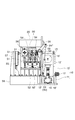
- the squeeze roll stand of this embodiment is installed at the joining position of the ERW pipe production line as shown in FIGS. 1 to 4, and passes through a group of forming rollers (not shown) and enters with the facing edge portion facing up. The opposite edge portions of the open pipe 60 to be joined are joined.
- the squeeze roll stand includes a fixed unit 10 installed at a joining position of the production line, a tilting movable unit 20 stacked on the fixed unit 10, and a lock mechanism 30 that fixes the movable unit 20 on the fixed unit 10. , And a drive mechanism 40 that tilts and drives the movable portion 20, and is combined with a bead grinding device 50 installed on the downstream side of the squeeze roll stand.
- the squeeze roll stand fixing part 10 includes a gantry 11 and a stand body 12 provided on the gantry 11.
- a lower roll 13 that supports the open pipe 60 from below and left and right side rolls 14 and 14 that press the open pipe 60 from both sides are provided.
- the lower roll 13 is a horizontal free roller that is rotatably supported by a lower bracket 13 '.
- the left and right side rolls 14, 14 are vertical rolls, and are rotatably supported by cantilevered supports 14 ', 14' with the support side facing outward.
- the supports 14 'and 14' on both sides are driven in a horizontal direction perpendicular to the line by hydraulic servo control cylinders 15 and 15 provided on both sides thereof. Thereby, the pushing amount of the left and right side rolls 14, 14 is adjusted.
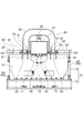
- the stand body 12 is composed of cylinder cases 15 'and 15' of the hydraulic servo control cylinders 15 and 15 on both sides and detachable front and rear frame panels 12 'and 12'.
- the front and rear edges and the left and right edges are substantially open (see FIG. 4).
- a pair of left and right first motors 16 and 16 for rotationally driving the side rolls 14 and 14 in the stand main body 12 are installed in the mount 11 of the fixing unit 10.
- a second motor 17 that drives the lower roll 13 in the stand main body 12 up and down is mounted on the gantry 11.
- the first motors 16 and 16 are arranged at both end portions in the gantry 11 with the output shaft facing inward.
- the rotation of each output shaft is attached to the gearboxes 16 'and 16' disposed inside thereof, a pair of left and right drive shafts 16 "and 16" disposed vertically in the stand body 12, and above them.
- the side rolls 14 and 14 are synchronously rotated by being transmitted to the upper side rolls 14 and 14 through the pair of left and right plug-in couplings 18 and 18, respectively.
- the left and right plug-in type couplings 18 and 18 are fixed to the upper ends of the drive shafts 16 ′′ and 16 ′′, and a connecting pin protruding downward from the lower ends of the side rolls 14 and 14 is inserted.
- the side rolls 14 and 14 are detachably connected.
- the plug-in couplings 18 and 18 are supported by horizontal guides 18 'and 18' perpendicular to the line so as to be movable in the lateral direction, and are guided to arbitrary positions in the lateral direction by motor-type jacks 18 "and 18". Is done.
- the drive shafts 16 ′′ and 16 ′′ are constituted by universal joints in order to allow lateral movement of the plug-in couplings 18 and 18, that is, change in pushing amount of the side rolls 14 and 14.
- the second motor 17 is mounted on the side edge of the front side (line upstream side) of the gantry 11 with the output shaft facing inward.
- the output shaft of the second motor 17 is connected to a direction changing gabbox 17 ′ mounted on the center of the front side (upstream line) of the gantry 11 and a jack 17 ′′ arranged in the stand body 12.
- the height of the lower roll 13 is adjusted by raising and lowering the bracket 13 'on the lever.
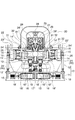
- the movable unit 20 on the fixed unit 10 includes an arch-shaped frame 25 having an inverted U shape when viewed from the front, and a pair of left and right upper rolls supported so as to be movable up and down in the frame 25. 26, 26.
- the inside of the arch-shaped frame 25 is open downward.
- the upper rolls 26 and 26 are composed of free rollers similar to the lower roll 13, and are arranged slightly inclined inward so as to press both edge portions of the open pipe 60 entering with the opposite edge portion facing upward from an obliquely upward direction. Yes.
- the upper rolls 26 and 26 are attached to a movable base 27 provided in the frame 25 so as to be movable up and down.
- the movable base 27 is driven up and down by a hydraulic servo control cylinder 28 attached to the center of the frame 25.
- a pair of left and right hydraulic servo control cylinders 29, 29 are mounted downward on the movable base 27, and guides 26 ′, 26 ′ for guiding the upper rolls 26, 26 are provided below the movable base 27.
- the hydraulic servo control cylinders 29 and 29 and the guides 26 ′ and 26 ′ are slightly inclined inward corresponding to the inclination of the upper rolls 26 and 26. Then, the height of the upper rolls 26 and 26 is independently adjusted by the lifting operation of the movable base 27 by the hydraulic servo control cylinder 28 and the lifting operation of the upper rolls 26 and 26 by the hydraulic servo control cylinders 29 and 29.
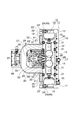
- the movable unit 20 is also configured to rotate about 90 degrees toward the back side (downstream line) of the fixed unit 10 around the upper end of the back side (line downstream) of the fixed unit 10.
- the movable portion 20 is horizontally disposed by a pair of left and right first brackets 21 and 21 fixed to an upper end portion on the back side (downstream line) of the fixed portion 10 and the first brackets 21 and 21. It has a pair of left and right rotating shafts 22 and 22 that are supported, and a pair of left and right second brackets 23 and 23 that are fixed to the lower end of the back side (the downstream side of the line) of the rotating unit 20.
- the left and right second brackets 23, 23 fixed to the lower end portion on the back side (downstream line) of the rotating portion 20 are respectively disposed inside the left and right first brackets 21, 21, and the rotation shaft 22 and 22 are fixed.
- the pair of left and right levers 24 ′ and 24 ′ fixed to both ends of the rotary shafts 22 and 22 are paired with left and right ends pivotally supported on both ends on the back side (downstream line) of the gantry 11.
- the actuators 24, 24 made of cylinders are axially attached to the tip ends of the rods.
- the rods of the actuators 24, 24 are retracted.
- the movable part 20 is The bead grinding apparatus 50 arranged on the back side (downstream side of the line) is tilted by about 90 degrees toward the back side (downstream side of the line) about the horizontal rotating shafts 22 and 22 on the back side (downstream of the line). It is placed on its back with the front facing up.
- the actuators 24 and 24 are drive mechanisms 40 that tilt and drive the movable portion 20. Further, the movable unit 20 tilts about 90 degrees toward the back side (downstream side of the line), and the supine state is placed with the front face up on the bead grinding apparatus 50 disposed on the back side (downstream side of the line). This is the retracted position of the movable unit 20.
- Reference numerals 22 'and 22' denote shaft support portions that rotatably support the left and right rotating shafts 22 and 22 inside the levers 24 'and 24'.
- the lock mechanism 30 that fixes the movable portion 20 on the fixed portion 10 is configured by a combination of a plurality of (herein, eight) clamps 31 provided on the upper surface of the fixed portion 10. ing. Of the eight clamps 31, four are attached to the upper surface of the front edge (front edge) of the fixed portion 10, and two are attached as a set, and the remaining four are the back of the fixed portion 10. Two sets of two are attached to the upper surface of the side edge (rear edge). Two sets of clamps 31 attached to the upper surface of the front edge portion are arranged on both sides sandwiching the central portion, and the two clamps 31, 31 of each set are arranged to face each other. Similarly, two sets of clamps 31 attached to the upper surface of the rear edge portion are arranged on both sides sandwiching the central portion, and the two clamps 31 and 31 of each set are arranged to face each other.
- the four groups of eight clamps 31 here are plate-like stoppers 32 and 32 on both sides protruding forward and backward from both lower ends of the frame 25 in the movable part 20 when the movable part 20 is in the assembly position on the fixed part 10.
- the fixing portion 10 To be fixed on the fixing portion 10. Specifically, the end portions of the two plate-like stoppers 32, 32 projecting upstream from the lower end portions of the frame 25 and the end portions of the two plate-like stoppers 32, 32 projecting downstream.
- the movable portion 20 is supported on the fixed portion 10 by engaging the front and rear edges of the fixed portion 10.
- the eight clamps 31 are hydraulic here, and the clamping force by them, that is, the force with which the eight clamps 31 fix the plate-like stoppers 32, 32 on both sides protruding forward and backward on the fixing portion 10,
- the load By setting the load to be greater than or equal to the load generated in the engaging and fixing portion when the tube is formed, rattling of the engaging and fixing portion is minimized and the squeeze roll stand is made highly rigid.
- the bead grinding device 50 provided continuously downstream of the fixed portion 10 allows the movable portion 20 to tilt to the retracted position downstream of the electric resistance weld line production line, as shown in FIGS.
- the height is limited so as to serve as a support for the movable part 20 below the movable part 20 tilted to the retracted position. Due to this height restriction, the bead grinding apparatus 50 employs the following unique configuration.
- the bead grinding apparatus 50 is spaced in the longitudinal direction of the line in order to support the main frame 55 arranged on the downstream side of the fixed portion 10 and the tubular material exiting the squeeze roll stand.
- the plurality of support rollers 51 are attached to a common support frame 52 that can be moved up and down, and the height of the support rollers 52 is increased by being driven up and down by a motor jack 52 ′ provided on the side of the line. Adjusted.
- a plurality of grinding blades 53 arranged with a plurality of support rollers 51 at intervals in the line longitudinal direction are attached to individual lifting frames 54.
- the plurality of lifting frames 54 are individually driven up and down by a plurality of motor jacks 54 ′ provided corresponding to each lifting frame on the side of the line, thereby individually adjusting the heights of the plurality of grinding blades 53.
- a plurality of lifting frames 54 that individually support the plurality of grinding blades 53 are respectively provided with position adjusting mechanisms that adjust the circumferential position of the grinding blade 53.
- the motor jack 52 ' which is the height adjusting mechanism of the plurality of support rollers 51
- the plurality of motor jacks 54' which are the height adjusting mechanisms of the plurality of lifting frames 54
- the bead grinding device 50 is reduced in height to such a level that the movable portion 20 can tilt about 90 degrees downstream.
- a bead winder unit 56 is disposed on the further downstream side of the plurality of grinding blades 53, and on the further downstream side of the main frame 55, a support upper roll unit 57. Is arranged.
- the support upper roll unit 57 is installed together with the main frame 55 on a pedestal 58 arranged on the downstream side of the squeeze roll stand.
- the main frame 55 of the bead grinding apparatus 50 is open, and during operation, the movable part 20 does not overlap therewith so that the bead grinding apparatus 50 is open. As a result, there is no stagnation of fumes, which is a preferable form from the work environment.
- the movable unit 20 of the squeeze roll stand is fixed to the assembly position on the fixed unit 10 by the lock mechanism 30 as shown in FIGS. 1 and 2.
- the squeeze rolls in the squeeze roll stand that is, the lower roll 13 and the left and right side rolls 14 and 14 in the fixed part 10
- the pair of left and right upper rolls 26 and 26 in the movable part 20 exist at fixed positions.
- the pair of left and right first motors 16 and 16 provided in the gantry 11 of the fixed part 10 are operated, the left and right side rolls 14 and 14 in the fixed part 10 are rotationally driven.
- the height of the lower roll 31 in the fixed portion 10 is adjusted by the second motor 17 on the gantry 11, and the amount of pushing of the left and right side rolls 14, 14 is adjusted by the hydraulic servo control cylinders 15, 15.
- the lateral positions of the plug-in couplings 18 and 18 are adjusted by motor jacks 18 ′′ and 18 ′′, and the heights of the upper rolls 26 and 26 in the movable portion 20 are adjusted by a hydraulic servo control cylinder 28, respectively.
- the height of the plurality of support rollers 51 is adjusted by the motor jack 52 ', and the height of the plurality of grinding blades 53 is adjusted by the plurality of motor jacks 54'.
- the open pipe 60 enters the squeeze roll stand with the opposite edge portion facing up, and is heated by a heating device (not shown), pushed by the left and right side rolls 14 and 14, and pressed by the left and right upper rolls 26 and 26, thereby facing the opposite edge.
- the parts are joined.
- the tubular material continues to enter the downstream bead grinding apparatus 50, and the outer surface bead generated in the joining portion is removed stepwise by the plurality of grinding blades 53, and the cross-sectional circular electric sewing as the product is performed. It is made a tube.
- the movable part 20 on the fixed part 10 in the squeeze roll stand tilts about 90 degrees toward the back side (downstream line) about the rotating shaft 22 on the back side (downstream line), and the back side (downstream line) bead.
- the upper surface of the fixed portion 10 is opened.
- the inside of the arch-shaped frame 25 in the movable part 20 is opened.
- the front and rear frame panels 12 'and 12' can be removed.
- the front surface and / or the rear surface of the fixed portion 10 is opened, so that the squeeze roll in the fixed portion 10 can be replaced more easily.
- the movable part 20 that is the upper roll assembly can be tilted to the downstream side of the line with respect to the fixed part 10 below, and is fixed by the tilting operation. Since the movable part 20 is retracted from above the part 10, the retracting operation is easier than when the upper roll assembly is lifted by a crane and separated from the lower fixed part 10. Moreover, since the retracted movable portion 20 is stacked on the back with the front facing up on the bead grinding apparatus 50 on the downstream side of the line, no temporary storage space is required outside the line. In addition, since the frame 55 of the bead grinding apparatus 50 also serves as a support for the movable portion 20, the configuration is simple.
- a roll change in the fixing unit 10 can be automatically performed by, for example, assembling a portal frame on the fixing unit 10.
- Various methods such as using a small hoist or using various cylinders are possible for automatic roll changing.
- the side rolls 14, 14 are connected to the lower drive shafts 16 ′′, 16 ′′ via plug-in couplings 18, 18.
- the side rolls 14 and 14 can be separated from the drive shafts 16 "and 16" simply by lifting them up.
- the lateral positions of the plug-in couplings 18 and 18 are adjusted by the motor type jacks 18 "and 18" according to the roll sizes. Keep it.
- the left and right side rolls 14 and 14 corresponding to the next product size can be connected to the lower drive shafts 16 ′′ and 16 ′′ only by setting the left and right side rolls 14 and 14 from above.
- the movable part 20 in order to exclude the movable part 20 on the fixed part 10 in the squeeze roll stand from the fixed part 10, the movable part 20 has a horizontal axis (rotary axis 22) perpendicular to the line downstream of the line.
- a horizontal axis perpendicular to the line downstream of the line.
- it is tilted to the downstream side of the line as a fulcrum, it can also be tilted to the upstream side of the line with a horizontal axis perpendicular to the line upstream of the line as a fulcrum. It is also possible to tilt it sideways.
- SYMBOLS 10 Fixed part 11 Base 12 Stand main body 13 Lower roll 14 Side roll 15 Hydraulic servo control cylinder 16 1st motor 17 2nd motor 18 Plug-in type coupling 20 Movable part 21 1st bracket 22 Rotating shaft 23 2nd bracket 24 Actuator 25 Frame 26 Upper roll 27 Movable base 28 Hydraulic servo control cylinder 29 Hydraulic servo control cylinder 30 Lock mechanism 31 Clamp 32 Plate-like stopper 40 Drive mechanism (actuator 24) DESCRIPTION OF SYMBOLS 50 Bead grinding apparatus 51 Support roller 52 Support frame 53 Grinding blade 54 Lifting frame 55 Main frame 56 Bead winder unit 57 Support upper roll unit 58 Base 60 Open pipe
Abstract
Description
11 架台
12 スタンド本体
13 下ロール
14 サイドロール
15 油圧サーボ制御シリンダー
16 第1モータ
17 第2モータ
18 差し込み式カップリング
20 可動部
21 第1ブラケット
22 回転軸
23 第2ブラケット
24 アクチュエータ
25 フレーム
26 上ロール
27 可動ベース
28 油圧サーボ制御シリンダー
29 油圧サーボ制御シリンダー
30 ロック機構
31 クランプ
32 板状ストッパー
40 駆動機構(アクチュエータ24)
50 ビード研削装置
51 支持ローラ
52 支持フレーム
53 研削刃物
54 昇降フレーム
55 メインフレーム
56 ビードワインダーユニット
57 サポート上ロールユニット
58 架台
60 オープンパイプ
Claims (10)
- 電縫管製造ラインの接合位置に設置され、左右の上ロールを除くスクイズロールが脱着可能に組み込まれた固定部と、該固定部上に重ねられ、内部に左右の上ロールが脱着可能に組み込まれると共に、固定部上の組み立て位置から、当該固定部上を開放する退避位置へ少なくとも一方向側を支点としてその側へ傾動する可動部と、該可動部を固定部上の組み立て位置に固定するロック機構と、前記可動部を組み立て位置と退避位置との間で往復駆動する駆動機構とを具備するスクイズロールスタンド。
- 請求項1に記載のスクイズロールスタンドにおいて、前記可動部は電縫管製造ラインの下流側に傾動するスクイズロールスタンド。
- 請求項2に記載のスクイズロールスタンドにおいて、前記固定部はライン下流側に設置されたビード研削装置と組み合わされており、前記可動部はライン下流側へ傾動した状態で前記ビード研削装置上に重なるスクイズロールスタンド。
- 請求項3に記載のスクイズロールスタンドにおいて、可動部がライン下流側へ直角に傾動するようにビード研削装置の高さが制限されているスクイズロールスタンド。
- 請求項4に記載のスクイズロールスタンドにおいて、ビード研削装置の高さ制限のために、ビード研削装置における支持ロール及び研削部の高さ調整機構がライン側方又は下方に配置されているスクイズロールスタンド。
- 請求項1~5の何れかに記載のスクイズロールスタンドにおいて、前記ロック機構は、可動部の下端部から正面側及び背面側に突出し、固定部上面の正面側の縁部及び背面側の縁部にそれぞれ係合する板状ストッパーと、固定部上面の正面側の縁部及び背面側の縁部に取り付けられて板状ストッパー係合部を両側から固定する複数のクランプとの組合せからなるスクイズロールスタンド。
- 請求項6に記載のスクイズロールスタンドにおいて、前記板状ストッパーは、可動部の支持部材を兼ねるスクイズロールスタンド。
- 請求項6又は7に記載のスクイズロールスタンドにおいて、前記複数のクランプは左右均等に配置されており、且つ当該スクイズロールスタンドにおける成形反力以上の荷重で前記板状ストッパーを常時押し付けるスクイズロールスタンド。
- 請求項1~8に記載のスクイズロールスタンドにおいて、前記固定部における左右のサイドロールが下方に配置された左右の駆動シャフトに対して左右の差し込み式カップリングを介して脱着可能に連結されており、左右の差し込み式カップリングは、ラインに直角な横方向に位置調節が可能であるスクイズロールスタンド。
- 請求項9に記載のスクイズロールスタンドにおいて、左右の駆動シャフトは、左右の差し込み式カップリングの横方向移動を許容するためにユニバーサルジョイントからなるスクイズロールスタンド。
Priority Applications (3)
| Application Number | Priority Date | Filing Date | Title |
|---|---|---|---|
| EP11863940.0A EP2700457B1 (en) | 2011-04-18 | 2011-07-29 | Squeeze roll stand |
| RU2013151069/02A RU2572931C2 (ru) | 2011-04-18 | 2011-07-29 | Шовообжимная клеть |
| US14/112,814 US9199290B2 (en) | 2011-04-18 | 2011-07-29 | Squeeze roll stand |
Applications Claiming Priority (2)
| Application Number | Priority Date | Filing Date | Title |
|---|---|---|---|
| JP2011091994A JP5781821B2 (ja) | 2011-04-18 | 2011-04-18 | スクイズロールスタンド |
| JP2011-091994 | 2011-04-18 |
Publications (1)
| Publication Number | Publication Date |
|---|---|
| WO2012144090A1 true WO2012144090A1 (ja) | 2012-10-26 |
Family
ID=47041232
Family Applications (1)
| Application Number | Title | Priority Date | Filing Date |
|---|---|---|---|
| PCT/JP2011/067464 WO2012144090A1 (ja) | 2011-04-18 | 2011-07-29 | スクイズロールスタンド |
Country Status (5)
| Country | Link |
|---|---|
| US (1) | US9199290B2 (ja) |
| EP (1) | EP2700457B1 (ja) |
| JP (1) | JP5781821B2 (ja) |
| RU (1) | RU2572931C2 (ja) |
| WO (1) | WO2012144090A1 (ja) |
Families Citing this family (4)
| Publication number | Priority date | Publication date | Assignee | Title |
|---|---|---|---|---|
| JP2018134643A (ja) * | 2015-07-09 | 2018-08-30 | 株式会社中田製作所 | 管の成形方法及び装置 |
| CN107185997B (zh) * | 2017-07-05 | 2019-09-17 | 宁波钜智自动化装备有限公司 | 一种多轴伺服控制高精度erw焊管成形机构 |
| JP6823212B1 (ja) | 2020-01-31 | 2021-01-27 | 株式会社中田製作所 | スクイズ装置 |
| CN115697579A (zh) | 2020-04-09 | 2023-02-03 | 株式会社中田制作所 | 金属管的制造方法和装置 |
Citations (9)
| Publication number | Priority date | Publication date | Assignee | Title |
|---|---|---|---|---|
| JPS60160927U (ja) * | 1984-04-03 | 1985-10-25 | 新日本製鐵株式会社 | 造管設備における内張りロ−ル交換装置 |
| JPH0685715U (ja) | 1993-05-26 | 1994-12-13 | 住友金属工業株式会社 | 溶接管の外面ビード切削装置 |
| JPH1058194A (ja) | 1996-08-26 | 1998-03-03 | Kawasaki Steel Corp | 電縫鋼管の外面ビード切削装置 |
| JP3053534B2 (ja) | 1994-09-30 | 2000-06-19 | 新日本製鐵株式会社 | スクイズロールスタンド |
| JP2001150189A (ja) | 1999-11-24 | 2001-06-05 | Puropurai:Kk | 電縫管の外面ビード切屑の切断方法及び外面ビード切屑切断装置 |
| JP2005511306A (ja) * | 2001-12-06 | 2005-04-28 | エスエムエス メーア ゲゼルシャフト ミット ベシュレンクテル ハフツング | 管溶接スタンドにおけるロール交換方法および装置 |
| JP2006088215A (ja) | 2004-09-27 | 2006-04-06 | Jfe Steel Kk | 電縫管の外面ビード屑処理装置 |
| JP4250848B2 (ja) | 2000-02-17 | 2009-04-08 | Jfeスチール株式会社 | スクイズスタンドのトップロール取替装置 |
| JP4461549B2 (ja) | 2000-02-17 | 2010-05-12 | Jfeスチール株式会社 | ロールスタンドの吊装置及びロール替え方法 |
Family Cites Families (8)
| Publication number | Priority date | Publication date | Assignee | Title |
|---|---|---|---|---|
| SU1092019A1 (ru) * | 1982-10-11 | 1984-05-15 | Предприятие П/Я Р-6930 | Устройство дл удалени сварочного грата |
| JPS60160927A (ja) | 1984-02-01 | 1985-08-22 | プリマハム株式会社 | 食品焼用フ−ド |
| SU1590272A1 (ru) * | 1988-03-21 | 1990-09-07 | Институт Электросварки Им.Е.О.Патона | Устройство дл удалени кольцевого грата |
| GB2226513B (en) * | 1988-11-29 | 1992-04-08 | Senior Bigwood Limited | Tube weld mill |
| WO1991008064A1 (fr) * | 1989-12-04 | 1991-06-13 | Kawasaki Steel Corporation | Procede et appareil de fabrication de tubes en acier soude |
| US5192013A (en) * | 1991-09-20 | 1993-03-09 | Abbey Etna Machine Company | Scarfing apparatus |
| US5461896A (en) * | 1994-02-18 | 1995-10-31 | Abbey Etna Machine Company | Automated changeover tube mill |
| RU2392076C1 (ru) * | 2009-08-10 | 2010-06-20 | Открытое акционерное общество "Электростальский завод тяжелого машиностроения" | Трубосварочная клеть |
-
2011
- 2011-04-18 JP JP2011091994A patent/JP5781821B2/ja active Active
- 2011-07-29 WO PCT/JP2011/067464 patent/WO2012144090A1/ja active Application Filing
- 2011-07-29 US US14/112,814 patent/US9199290B2/en not_active Expired - Fee Related
- 2011-07-29 EP EP11863940.0A patent/EP2700457B1/en not_active Not-in-force
- 2011-07-29 RU RU2013151069/02A patent/RU2572931C2/ru not_active IP Right Cessation
Patent Citations (9)
| Publication number | Priority date | Publication date | Assignee | Title |
|---|---|---|---|---|
| JPS60160927U (ja) * | 1984-04-03 | 1985-10-25 | 新日本製鐵株式会社 | 造管設備における内張りロ−ル交換装置 |
| JPH0685715U (ja) | 1993-05-26 | 1994-12-13 | 住友金属工業株式会社 | 溶接管の外面ビード切削装置 |
| JP3053534B2 (ja) | 1994-09-30 | 2000-06-19 | 新日本製鐵株式会社 | スクイズロールスタンド |
| JPH1058194A (ja) | 1996-08-26 | 1998-03-03 | Kawasaki Steel Corp | 電縫鋼管の外面ビード切削装置 |
| JP2001150189A (ja) | 1999-11-24 | 2001-06-05 | Puropurai:Kk | 電縫管の外面ビード切屑の切断方法及び外面ビード切屑切断装置 |
| JP4250848B2 (ja) | 2000-02-17 | 2009-04-08 | Jfeスチール株式会社 | スクイズスタンドのトップロール取替装置 |
| JP4461549B2 (ja) | 2000-02-17 | 2010-05-12 | Jfeスチール株式会社 | ロールスタンドの吊装置及びロール替え方法 |
| JP2005511306A (ja) * | 2001-12-06 | 2005-04-28 | エスエムエス メーア ゲゼルシャフト ミット ベシュレンクテル ハフツング | 管溶接スタンドにおけるロール交換方法および装置 |
| JP2006088215A (ja) | 2004-09-27 | 2006-04-06 | Jfe Steel Kk | 電縫管の外面ビード屑処理装置 |
Non-Patent Citations (1)
| Title |
|---|
| See also references of EP2700457A4 |
Also Published As
| Publication number | Publication date |
|---|---|
| JP2012223782A (ja) | 2012-11-15 |
| EP2700457A1 (en) | 2014-02-26 |
| EP2700457A4 (en) | 2014-12-31 |
| RU2013151069A (ru) | 2015-05-27 |
| EP2700457B1 (en) | 2015-11-04 |
| US20140130562A1 (en) | 2014-05-15 |
| US9199290B2 (en) | 2015-12-01 |
| JP5781821B2 (ja) | 2015-09-24 |
| RU2572931C2 (ru) | 2016-01-20 |
Similar Documents
| Publication | Publication Date | Title |
|---|---|---|
| JP5221412B2 (ja) | カーカスプライの接合装置 | |
| JP5781821B2 (ja) | スクイズロールスタンド | |
| JP6077895B2 (ja) | ターニングローラ装置 | |
| CN105499758B (zh) | 片头与散热管的自动焊机 | |
| US11219933B2 (en) | Apparatus and method for support and controlled advancement of a metal sheet in a bending machine for obtaining cylindrical or truncated cone structures | |
| JP6307552B2 (ja) | 水平型自動溶接装置 | |
| KR20080086964A (ko) | 러그 절단장치 | |
| CN111168278A (zh) | 一种自动焊接机 | |
| JP2011241010A (ja) | シート材の位置調整装置 | |
| CN102601616B (zh) | 一种剪切对齐机构 | |
| KR101563915B1 (ko) | 강관 내면 용접설비 | |
| KR100957904B1 (ko) | 압연 제품 교정기의 교정롤 교체장치 | |
| WO2021153164A1 (ja) | スクイズ装置 | |
| KR20090054074A (ko) | 다수의 리브 동시 용접 장치 | |
| CN205464736U (zh) | 片头与散热管的自动焊机 | |
| KR100962095B1 (ko) | 리브 용접 장치의 가이드 장치 | |
| JP7194980B2 (ja) | 溶接ビード切削装置 | |
| KR20040083857A (ko) | 유로폼의 프레임용 자동 용접장치 | |
| JP5398014B2 (ja) | 電縫管スクイズミル | |
| KR20100020697A (ko) | 자동 나이프 조립체 체인징 장치 | |
| KR102581807B1 (ko) | 용접이음부의 높이차 미세조절이 가능한 조관장치 | |
| CN204975752U (zh) | 短直管与法兰调速定面滚动手工焊接流水线 | |
| KR200317625Y1 (ko) | 유로폼의 프레임용 자동 용접장치 | |
| CN105346117B (zh) | 压辊装置及其加工装配方法 | |
| CN113878072A (zh) | 钢筋笼加工设备 |
Legal Events
| Date | Code | Title | Description |
|---|---|---|---|
| 121 | Ep: the epo has been informed by wipo that ep was designated in this application |
Ref document number: 11863940 Country of ref document: EP Kind code of ref document: A1 |
|
| NENP | Non-entry into the national phase |
Ref country code: DE |
|
| WWE | Wipo information: entry into national phase |
Ref document number: 2011863940 Country of ref document: EP |
|
| ENP | Entry into the national phase |
Ref document number: 2013151069 Country of ref document: RU Kind code of ref document: A |
|
| WWE | Wipo information: entry into national phase |
Ref document number: 14112814 Country of ref document: US |