WO2012141295A1 - 光学系の調整方法、光学系の調整装置、及び撮像素子の調整方法 - Google Patents
光学系の調整方法、光学系の調整装置、及び撮像素子の調整方法 Download PDFInfo
- Publication number
- WO2012141295A1 WO2012141295A1 PCT/JP2012/060143 JP2012060143W WO2012141295A1 WO 2012141295 A1 WO2012141295 A1 WO 2012141295A1 JP 2012060143 W JP2012060143 W JP 2012060143W WO 2012141295 A1 WO2012141295 A1 WO 2012141295A1
- Authority
- WO
- WIPO (PCT)
- Prior art keywords
- optical system
- lens
- optical
- holder
- arm portion
- Prior art date
- Legal status (The legal status is an assumption and is not a legal conclusion. Google has not performed a legal analysis and makes no representation as to the accuracy of the status listed.)
- Ceased
Links
Images


Classifications
-
- G—PHYSICS
- G02—OPTICS
- G02B—OPTICAL ELEMENTS, SYSTEMS OR APPARATUS
- G02B7/00—Mountings, adjusting means, or light-tight connections, for optical elements
- G02B7/003—Alignment of optical elements
-
- G—PHYSICS
- G01—MEASURING; TESTING
- G01B—MEASURING LENGTH, THICKNESS OR SIMILAR LINEAR DIMENSIONS; MEASURING ANGLES; MEASURING AREAS; MEASURING IRREGULARITIES OF SURFACES OR CONTOURS
- G01B11/00—Measuring arrangements characterised by the use of optical techniques
- G01B11/26—Measuring arrangements characterised by the use of optical techniques for measuring angles or tapers; for testing the alignment of axes
- G01B11/27—Measuring arrangements characterised by the use of optical techniques for measuring angles or tapers; for testing the alignment of axes for testing the alignment of axes
-
- G—PHYSICS
- G02—OPTICS
- G02B—OPTICAL ELEMENTS, SYSTEMS OR APPARATUS
- G02B27/00—Optical systems or apparatus not provided for by any of the groups G02B1/00 - G02B26/00, G02B30/00
- G02B27/62—Optical apparatus specially adapted for adjusting optical elements during the assembly of optical systems
-
- G—PHYSICS
- G02—OPTICS
- G02B—OPTICAL ELEMENTS, SYSTEMS OR APPARATUS
- G02B7/00—Mountings, adjusting means, or light-tight connections, for optical elements
- G02B7/02—Mountings, adjusting means, or light-tight connections, for optical elements for lenses
- G02B7/023—Mountings, adjusting means, or light-tight connections, for optical elements for lenses permitting adjustment
Definitions
- the present invention relates to an optical system adjustment method for adjusting an optical system, an optical system adjustment device, and an image sensor adjustment method.
- the camera's photographic lens has a plurality of lenses held in a holder (lens holder) and is incorporated in a lens barrel.
- a holder lens holder
- inexpensive and lightweight plastic lens holders are frequently used.
- optical characteristics of an optical system incorporated in a lens barrel are evaluated, and when the evaluation value is not within an allowable range, adjustment such as optical axis alignment of a lens is performed using an adjustment screw or the like.
- an optical system adjustment method in which a holder made of a plastic molding member for holding an optical component is attached to a lens barrel.
- An evaluation process for forming an image of a predetermined pattern by an optical system assembled by the assembly process, evaluating an optical characteristic of the optical system based on the formed pattern image, and an evaluation result of the evaluation process And a correction step of correcting the shape of the holder by irradiating a predetermined portion of the holder with laser light.
- the evaluation step takes an image of a predetermined pattern formed by the optical system assembled in the assembly step with the imaging device. It is preferable to generate image data and evaluate the optical characteristics of the optical system based on the image data.
- the correcting step applies the first predetermined portion of the holder so as to incline the optical axis of the optical component. It is preferable to correct the shape by irradiating a laser beam.
- the correction step further includes a holder so as to displace the optical component along a plane substantially perpendicular to the optical axis. It is preferable to correct the shape by irradiating a second predetermined portion different from the first predetermined portion with laser light.
- the correction step is such that the optical component is displaced along a plane substantially perpendicular to the optical axis of the optical component. It is preferable to correct the shape by irradiating the first predetermined portion of the holder with laser light.
- the correction step is different from the first predetermined portion of the holder so as to further incline the optical axis of the optical component. It is preferable to correct the shape by irradiating the second predetermined portion with laser light.
- the predetermined part is preferably located between the optical component and the lens barrel.
- the correcting step includes forming a groove in a predetermined portion of the holder by laser light irradiation. It is preferable to modify the shape of the holder.
- the optical system adjustment method in the optical system adjustment method according to the first aspect, it is preferable to use a test chart having a plurality of patterns as the predetermined pattern.
- the optical component is a lens
- the holder is a frame portion that holds the outer periphery of the lens, and the optical axis of the lens.
- a first arm portion extending from the frame portion along a vertical surface, and a first arm portion extending from a side portion of the first arm portion along a surface perpendicular to the optical axis of the lens at a predetermined angle.
- a second arm portion, and the first arm portion is supported by the lens barrel so that the first arm portion can swing in a plane perpendicular to the optical axis of the lens at the tip portion, and the second arm portion is
- the first arm portion is fixed to the lens barrel at the distal end portion thereof, and the correcting step includes irradiating a laser beam at a predetermined position of the first arm portion as a first predetermined portion to incline the optical axis of the lens.
- the predetermined angle of the second arm portion is changed by irradiating a predetermined position of the second arm portion with a laser beam. It is preferable to deform the second arm portion so as to.
- the optical component is a lens
- the holder is a frame portion that holds the outer periphery of the lens, and the optical axis of the lens.
- a first arm portion extending from the frame portion along a vertical surface, and a first arm portion extending from a side portion of the first arm portion along a surface perpendicular to the optical axis of the lens at a predetermined angle.
- a second arm portion, and the first arm portion is supported by the lens barrel so that the first arm portion can swing in a plane perpendicular to the optical axis of the lens at the tip portion, and the second arm portion is
- the tip is fixed to the lens barrel, and the correction step is performed by irradiating a predetermined position of the second arm portion with a laser beam as a first predetermined portion so that the predetermined angle changes.
- Deform and tilt the optical axis of the lens by irradiating a predetermined position of the first arm as a second predetermined portion with laser light It is preferable to deform the first arm portion so as to.
- the plastic molding member is preferably a plastic member molded by an injection molding method.
- the holder is preferably a lens holding part that holds the photographing lens of the digital camera.
- a digital camera includes a lens barrel that houses an optical system having an optical component held by a holder whose shape has been corrected by the optical system adjustment method of the thirteenth aspect. Configured as follows.
- an optical system adjusting device comprising: a supporting means for fixing and supporting a lens barrel that houses an optical system having an optical component held by a holder made of a plastic molding member; An imaging unit that generates an image data by capturing an image of a predetermined pattern by an optical system housed in a lens barrel supported by the lens, and an evaluation that evaluates optical characteristics of the optical system based on the image data generated by the imaging unit And a laser beam irradiating unit that corrects the shape of the holder by irradiating a predetermined portion of the holder made of a plastic molding member with a laser beam based on the evaluation result of the evaluation unit.
- a method for adjusting an image sensor the attaching step of attaching a holder made of a plastic molding member that holds the image sensor to the camera body, the image sensor and an image of a predetermined pattern,
- An optical system is arranged between the image sensor to capture a predetermined pattern, and an evaluation process for evaluating the imaging characteristics of the image sensor based on the pattern image formed by the image sensor, and holding based on the evaluation result of the evaluation process
- a correcting step of correcting the shape of the holder by irradiating a predetermined part of the tool with laser light.
- optical characteristics are evaluated in a state where an optical system including an optical component held by a holder made of a plastic molding member is incorporated in a lens barrel, and the evaluation is performed. Since the shape of the holder is corrected by irradiating a predetermined portion of the holder with the laser beam based on the result, the optical system can be easily adjusted.
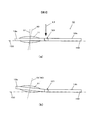
- FIG. 1 is a block diagram schematically showing an optical system adjusting apparatus according to an embodiment of the present invention.
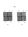
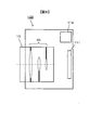
- FIG. 2A is a diagram schematically illustrating a test chart used for adjustment of the optical system
- FIG. 2B is a diagram schematically illustrating an image of the test chart formed by the optical system.
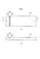
- FIG. 3 is a side view schematically showing a lens holder irradiated with laser light in the first embodiment
- FIG. 3A is a lens holder before laser light irradiation
- FIG. 3B is laser light. It is a lens holder after irradiation.
- FIGS. 4A and 4B are schematic views showing an example of formation of engraving lines by irradiating a lens holder with laser light.
- FIG. 4A is a plan view and FIG. 4B is a cross-sectional view taken along the line AA.
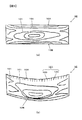
- FIG. 5 is a partial cross-sectional view schematically showing the internal stress distribution before and after the laser beam irradiation to the lens holder
- FIG. 5A is a diagram showing the internal stress distribution before the laser beam irradiation
- FIG. These are figures which show internal stress distribution after laser beam irradiation.
- FIG. 6 is a diagram schematically showing the inside of the digital camera in which the lens barrel shown in FIG. 1 is housed.
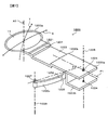
- FIG. 7 is a perspective view schematically showing a lens holder irradiated with laser light in the second embodiment.
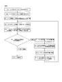
- FIG. 8 is a flowchart showing an optical system adjustment method according to an embodiment of the present invention.
- FIG. 9 is a diagram schematically showing the adjustment of the image sensor according to the embodiment of the present invention.
- the adjusting device 1 is for adjusting an optical system 20 of a photographing lens barrel for a camera, a support base 2 on which the lens barrel 10 is mounted and fixedly supported, and an imaging device. 3, an evaluation device 4, an irradiation control device 5, and a laser marker 6 as laser light irradiation means.
- the imaging apparatus has an imaging surface inside, and the image of the test chart 7 is formed on the imaging surface by the optical system 20 instructed to fix to the support 2.
- the imaging device generates image data from the formed image.
- the evaluation device 4 calculates evaluation data related to the tilt amount and shift amount of the optical system 20 based on the comparison between the image data and the reference image data.
- the irradiation control device 5 calculates the irradiation condition of the laser beam irradiated by the laser marker 6 based on the evaluation data calculated by the evaluation device 4, and controls the laser marker 6 so that the laser beam is irradiated under the irradiation condition. That is, a laser beam irradiation condition for tilt correction for correcting the tilt amount and a laser beam irradiation condition for shift correction for correcting the shift amount are respectively set, and laser light is irradiated under these irradiation conditions. Thus, the laser marker 6 is controlled.
- the laser light irradiation conditions are, for example, values regarding the output value of the laser light, the irradiation range, the number of irradiations, the irradiation time, the duty ratio when performing pulse irradiation, and the like.
- the relationship between the values of these items and the tilt amount and shift amount to be corrected is prepared in the adjustment device as a laser light irradiation condition table.
- the laser marker 6 is, for example, a carbon dioxide laser (CO 2 laser), and irradiates a predetermined portion 121 of the first lens holder 12 with laser light L 1 based on control by the irradiation control device 5.
- the laser marker 6 can move in the vertical and horizontal directions within a plane perpendicular to the optical axis of the optical system 20.
- the lens barrel 10 to be adjusted includes a first lens holder 12 that holds the first lens 11, a second lens holder 22 that holds the second lens 21, and a third lens.
- a third lens holder 32 holding 31 is housed.
- the first, second, and third lenses 11, 21, and 31 constitute the photographing optical system 20.
- the optical system 20 is shown with only three convex lenses 11, 21 and 31, and the other lenses are not shown.
- the first, second, and third lens holders 12, 22, and 32 are all plastic molded products that are injection molded by an injection molding machine. Each of these lens holders 12, 22, and 32 has a vertically long plate shape, one end of which holds the first, second, and third lenses 11, 21, and 31, and the other end of the lens barrel 10. It can be attached to the circumference.
- the lenses 11, 21, and 31 are attached to the lens holders 12, 22, and 32, respectively (step S1).
- the lens holders 12, 22, and 32 are attached to the inner periphery of the lens barrel 10. These lens holders are attached so that the optical axes of the lenses 11, 21, and 31 substantially coincide with the optical axis A0 of the optical system 20 (step S2).
- the influence of the tilt of the optical axis of the lens on the optical performance of the optical system 20, that is, aberration, is not the same for each lens constituting the optical system. Even if the tilt amounts of the lenses 11, 21, and 31 are equal, the influence on the optical performance due to the tilt varies depending on the power and relative position of the lenses 11, 21, and 31.
- the first lens 11 has the strongest power among all the lenses constituting the optical system 20, and the tilt amount has the greatest influence on the optical performance of the optical system 20. In the embodiment, the tilt of the first lens 11 is corrected.
- step S3 the lens barrel 10 is fixed to the support base 2 of the adjusting device 1 (step S3).
- the test chart 7 having a predetermined pattern is imaged in front of the lens barrel 10 (right side in the figure). That is, the test chart is imaged by the optical system 20 to form an image of a predetermined pattern.
- the optical system 20 forms an image 70 of the test chart 7 on the imaging surface of the imaging device 3, and the imaging device 3 captures the image 70 and generates captured image data (step S4).
- the evaluation device 4 includes a storage unit that stores reference image data representing the test chart 7 in advance, and compares the reference image data stored in the storage unit with the captured image data from the imaging device 3. Next, the resolution and distortion of the gray patterns 70a to 70d (in this embodiment, the gray pattern 70a) are detected, and evaluation data relating to the resolution and distortion is calculated (step S5).
- step S6 based on the evaluation data calculated in step S5, it is evaluated whether or not the optical characteristics of the optical system 20 are within the allowable range (step S6).
- FIG. 2A shows the test chart 7.
- the test chart 7 has light and shade patterns 7a, 7b, 7c, and 7d in four regions on the upper right, upper left, lower left, and lower right of the chart surface, respectively.
- the density pattern 7a in the upper right area and the lower left area of the test chart 7 is a horizontal stripe
- the intensity pattern 7b in the upper left area and the lower right area is a vertical stripe.
- the test chart 7 is composed of stripes in different directions, a test chart in which the stripe directions are all the same may be used.
- FIG. 2B schematically shows an image 70 of the test chart 7 formed by the optical system 20.
- the shading patterns 70a to 70d of the image 70 correspond to the shading patterns 7a to 7d of the test chart 7 in FIG.
- the shading pattern 70a is a pattern having a reduced resolution compared to the other shading patterns 70b to 70d. This is because the optical system 20 is poorly adjusted, that is, the first lens holder 12 is not mounted correctly. Specifically, the optical axis of the first lens 11 is inclined with respect to the optical axis A0 of the optical system 20. This is due to tilt.
- the other shade patterns 70b to 70d reproduce the shade patterns 7b to 7d of the test chart 7 almost accurately.
- the relationship between the tilt amount and tilt direction of the first lens 11 and the resolution reduction and distortion of the light and shade patterns 70a to 70d of the image 70 will be described in detail below.
- the tilt amount of the first lens 11 increases, that is, as the deviation angle between the optical axis of the first lens 11 and the optical axis A0 of the optical system 20 increases, the resolution of the gray patterns 70a to 70d decreases and distortion also occurs. growing.
- the tilt direction of the first lens 11 determines the light / dark patterns 70a to 70d having the lowest resolution and the largest distortion.
- the optical characteristics of the optical system 20 are within the allowable range by evaluating the evaluation data relating to the reduction in resolution and the magnitude of distortion. If it is determined that the optical characteristics of the optical system 20 are within the allowable range, it is determined that the optical characteristics of the optical system 20 are good, and the evaluation ends (step 11).
- the amount of tilt correction of the first lens 11 is known based on the evaluation data, and the resolution degradation and distortion are the largest.
- the tilt direction of the first lens 11 can be determined from the evaluation result of the light and shade pattern (step S7).
- the tilt direction is limited to a specific direction.
- the drawing is simplified to show the influence of the mounting failure of the first lens holder 12, and only the light and shade pattern 70a is shown as having a reduced resolution.
- the light and shade pattern 70a greatly reduces the resolution and causes large distortion.
- the other light and dark patterns 70b to 70d also cause a corresponding decrease in resolution or distortion.
- the irradiation control device 5 sets a laser beam irradiation condition for tilt correction from the laser beam irradiation condition table. Thereby, values such as the output value of the laser beam irradiated from the laser marker 6, the irradiation range, the number of irradiations, the irradiation time, and the duty ratio when performing pulse irradiation are set (step S8).
- the laser marker 6 is moved to the irradiation position so that the laser beam is irradiated onto a predetermined part of the first lens holder 12 (step S9).
- the laser lens 6 irradiates a predetermined portion of the first lens holder 12 with a laser beam to deform the first lens holder 12 (step S10).
- the tilt of the first lens 11 is corrected, that is, adjusted.
- the predetermined portion 121 is determined in advance in consideration of the shape and size of the first lens holder 12, the characteristics of the lens held by the first lens holder 12, and the like.
- the predetermined portion 121 irradiated with the laser light is positioned on the arm portion 12b near the boundary between the arm portion 12b and the frame portion 12a. Stipulated.
- the image of the test chart 7 is picked up again by the image pickup device 3 by the optical system 20 to generate picked-up image data (step S4).
- evaluation data is calculated by the evaluation device 4 (step S5). Based on the evaluation data, it is confirmed whether or not the optical characteristics of the optical system 20 are within an allowable range (step S6). If the optical characteristics of the optical system 20 are not within the allowable range, the fine adjustment of the tilt of the first lens 11 is performed by repeating the step 7 and subsequent steps and adding fine deformation to the first lens holder 12. You can also.
- FIG. 3A shows a specific shape of the first lens holder 12 at the time of injection molding
- FIG. 3B shows the first shape after the laser beam L1 is applied to the part 121 of the arm portion 12b. 1 shows one lens holder 12.
- the first lens holder 12 has a frame portion 12a that holds the outer periphery of the first lens 11, and an arm portion 12b that continues to the frame portion 12a. These frame portion 12a and the arm portion. 12b extends along a straight line 130 indicated by a one-dot chain line during injection molding.
- the first lens holder 12 When such a first lens holder 12 is attached to the inner peripheral portion of the lens barrel 10 at the distal end portion 140 of the arm portion 12b, the first lens holder 12 is attached slightly inclined with respect to the inner peripheral portion of the lens barrel. Assume that the optical axis A1 of the first lens 11 is slightly inclined with respect to the optical axis A0 of the optical system 20. In order to correct such an inclination of the optical axis A1 of the first lens 11, that is, a tilt, the laser beam L1 is irradiated from the laser marker 6 to the part 121 of the arm portion 12b, and the first lens holder 12 is deformed.
- the laser beam L1 is scanned and irradiated so as to cross the irradiation part 121 of the arm part 12b in the width direction of the arm part.
- a shallow groove that is, a score line 120 is formed in the vicinity of the surface of the irradiation part 121 of the arm portion 12b.
- the score line 120 crosses the arm portion 12b in the width direction from one end to the other end.
- a plurality of engraving lines 120 formed by scanning irradiation with such laser light L1 are formed in parallel with each other at a predetermined interval.
- the plurality of engraved lines 120 are formed in parallel with each other at an equal interval of 0.14 mm, for example.
- the line width is preferably in the range of 0.05 mm to 0.5 mm.
- Such a plurality of engraved lines 120 can be formed by the laser marker 6 deflecting the laser beam L1 in the longitudinal direction of the lens holder 12 and emitting it, and the position of the laser marker 6 is determined by the lens. It can also be formed by moving a small amount in the longitudinal direction of the holder 12 and irradiating the laser beam L1.
- the engraved line 120 is not limited to a linear groove, and may be a discontinuous groove, for example, a series of small holes.
- the first lens holder 12 By forming a plurality of engraved lines 120 by such laser light irradiation, the first lens holder 12 is deformed in the vicinity of the irradiated region 121 as shown in FIG. Tilt by a predetermined angle. Due to the inclination of the frame portion 12a, the optical axis A1 of the first lens 11 is inclined by a predetermined angle and substantially coincides with the optical axis A0 of the optical system 20. Thus, the tilt adjustment of the first lens 11 is performed in a state where the first lens holder 12 is attached to the lens barrel 10.
- the amount of deformation of the first lens holder 12 by laser light irradiation is determined by the number of engraved lines 120, the width and depth of the engraved lines 120, and the like. Specifically, the inclination angle can be increased by increasing the number of the score lines 120, increasing the width of the score lines 120, increasing the depth of the score lines 120, and the like.
- FIG. 5 is a view for explaining the reason why the plastic molded product is deformed by the irradiation of the laser beam, and shows an enlarged partial cross section of the irradiation part 121 of the first lens holder 12.
- FIG. 5A shows the internal stress distribution remaining in the first lens holder 12 which is a plastic molded product before laser light irradiation
- FIG. 5B shows the first state in the state of FIG.
- the internal stress distribution after forming a plurality of score lines 120 on the lens holder 12 by laser beam irradiation is shown.
- These internal stress distributions are represented by contour stripes 101, and the positions having the same stress value are connected by a single line segment.
- Such a stress distribution is caused by the molten plastic pressure in the mold when the first lens holder 12 is molded, the cooling rate in the cooling process, and the like.
- the internal stress distribution of the first lens holder 12 is almost symmetrical between the upper surface 12A side and the lower surface 12B side, and the stresses on the upper surface and the lower surface are balanced.
- the upper surface 12A and the lower surface 12B are planes parallel to each other.
- the score line 120 is formed only on the upper surface 12A of the first lens holder 12
- the stress on the upper surface 12A side is released, so that the upper surface 12A has a concave shape. A shape change that bends occurs.
- the degree of such a shape change varies depending on the laser light irradiation conditions of the laser marker 6 for the same material and the same size plastic member.
- the main irradiation conditions are laser output value, irradiation range (area of engraved area), and irradiation time.
- a large shape change can be obtained by increasing the width or depth of the score line 120 or increasing the number of the score lines 120.
- a larger shape change can be obtained also by forming the plurality of score lines 120 shown in FIGS. 4 and 5 at a plurality of positions with a predetermined interval.
- the first lens holder 12 is deformed by the laser light irradiation on the first lens holder 12, and the optical axis of the first lens 11 is adjusted to coincide with the optical axis A0 of the optical system 20.
- FIG. 6 is a diagram schematically showing the internal configuration of the digital camera.
- the digital camera 100 houses the lens barrel 10 having the optical system 20 adjusted by the adjusting device 1 of the present embodiment, the image sensor 111, and the electronic viewfinder 112.
- An optical system 20 in the lens barrel 10 is used as a photographic lens. Since the optical axis of the optical system 20 is adjusted by the optical system adjustment method of the present embodiment, a high-quality captured image can be obtained.
- the adjustment device 1 and the adjustment method of the optical system of the present embodiment the following operational effects are obtained.
- (2) The optical performance of the optical system 20 is evaluated in a state where all the lenses are incorporated in the lens barrel 10, and the first lens holder 12 is irradiated with laser light based on the evaluation data. Since the inclination of the optical axis is adjusted, the adjustment work can be automated.
- the first lens 11 has the strongest power among all the lenses constituting the optical system 20, and therefore the tilt amount of the first lens 11 is the optical performance of the optical system 20. The tilt of the first lens 11 has been corrected.
- the laser marker 6 is moved to the position 6A of the two-dot chain line facing the second lens holder 22. In this state, the image of the test chart 7 is picked up and the picked-up data is evaluated. Based on the evaluation result, the laser marker 6 irradiates the predetermined irradiation site of the second lens holder 22 with the laser light L1A. Therefore, as shown in FIG. 1, the laser marker 6 can be moved vertically and horizontally in a plane perpendicular to the optical axis of the optical system 20.
- the first lens holder 12 and the second lens holder 22 are arranged so that their attachment positions with respect to the inner peripheral surface of the lens barrel 10 are greatly different in angle. Keep it. In the illustrated example, the state is shifted by 180 degrees. Thereby, when the laser marker 6 irradiates the second lens holder 22 with the laser beam, there is no possibility that the first lens holder 12 blocks the laser beam.
- the lens holder positioned closer to the imaging device 3 than the lens holder irradiated with the laser light does not overlap the lens holder targeted for laser light irradiation as viewed from the laser marker 6.
- the lens holder to be irradiated with the laser beam and the lens holder located in front of it (on the imaging device side) are attached to the lens barrel 10 at different angular positions.
- the laser marker 6 is moved to irradiate the second lens holder 22 with the laser beam.
- a deflecting member such as a mirror is inserted and removed.
- mirrors may be inserted on the broken line indicated by L1 and the broken line indicated by L1A, respectively, so that the laser light L1 is moved to the laser light L1A.
- the lens holder 12 is irradiated with laser light to adjust the tilt of the optical axis of the lens 11.
- two adjustments are performed: tilt of the optical axis of the lens and shift of the optical axis with the optical system 20 incorporated in the lens barrel 10.
- the lens shift is a shift in the plane in which the optical axis of the lens is perpendicular to the optical axis of the optical system 20.
- the adjustment device of the present embodiment is also almost the same as the adjustment device 1 shown in FIG. 1, and the difference from the adjustment device 1 is the shape of the lens holder.
- the lens to be adjusted is the first lens 11 in FIG. 1 as in the first embodiment.
- the first lens 11 is held by the first lens holder 12, but in the second embodiment, the first lens 11 is a lens as shown in FIG.
- the lens holder 1200 is attached to the inner periphery of the lens barrel 10.
- a lens holder 1200 is connected to a frame portion 1200a that holds the outer periphery of the first lens 11, a first arm portion 1200b that is connected to the frame portion 1200a, and a first arm portion 1200b. Second arm portion 1200c.
- the first arm portion 1200b has a stepped portion 1222 having a shape in which a flat plate is bent, and has forked portions 1223a and 1223b branched in a shape at the tip of the first arm portion.
- the first arm portion 1200b has an irradiation region 1221 that irradiates the laser beam L1 in the vicinity of the boundary with the frame portion 1200a.
- Each of the bifurcated portions 1223a and 1223b is formed with a through hole 1224, and a shaft portion 1225 indicated by a dotted line is inserted into the through hole 1224.
- the shaft portion 1225 extends in parallel with the optical axis A1 of the first lens 11, and both ends thereof are fixed to the inner peripheral portion of the lens barrel 10.
- the first arm portion 1200b is supported so as to be rotatable about the shaft portion 1225.
- the through hole 1224 is positioned on a straight line P1 that extends in the extending direction of the first arm portion 1200b through the center of the first lens 11.
- One end of the second arm portion 1200c is fixed to the bifurcated portion 1223b, and protrudes from the first arm portion 1200b in a direction perpendicular to the optical axis of the optical system 20 in FIG.
- the entire second arm portion 1200c is slightly curved, a recess 1227 is formed at the other end, and a shaft portion 1228 indicated by a dotted line is inserted into the recess 1227.
- the shaft portion 1228 extends in parallel with the optical axis A1 of the first lens 11, and both ends thereof are fixed to the inner peripheral portion of the lens barrel 10.
- the second arm portion 1200c protrudes from the first arm portion 1200b at an acute angle ⁇ with respect to the straight line P1 on the first arm portion 1200b. Further, the second arm portion 1200c has an irradiation region 1226 in the vicinity of one end fixed to the bifurcated portion 1223b. The irradiation area 1226 is defined on a plane parallel to the optical axis A1 of the first lens 11.
- the optical system 20 of the lens barrel 10 forms an image of the test chart 7 on the imaging surface of the imaging device 3 with all the lens holders including the lens holder 1200 attached to the lens barrel 10. .
- the imaging device 3 captures this image and generates image data.
- the evaluation device 4 calculates evaluation data related to the tilt amount and shift amount of the optical system 20 based on the comparison between the image data and the reference image data. Based on this evaluation data, the irradiation control device 5 uses a tilt laser light irradiation condition for correcting the tilt amount of the first lens 11 and a shift laser for correcting the shift amount of the first lens 11. Each light irradiation condition is calculated.
- the laser marker 6 irradiates the irradiation region 1221 on the first arm portion 1200b with the laser beam L1 based on the tilting laser beam irradiation condition.
- a plurality of engraving lines 1231 are formed in the irradiation region 1221, the first arm portion 1200 is deformed in the irradiation region 1221, and the frame portion 1200 a is inclined as indicated by the symbol T so that the first lens 11 is tilted.
- the tilt of the optical axis A1 is adjusted.
- the laser marker 6 irradiates the irradiation region 1226 of the second arm portion 1200c with the laser beam L1 based on the laser beam irradiation condition for shifting.
- a plurality of engraved lines 1232 are formed in the irradiation region 1226.
- the direction in which these engraved lines 1232 are formed is substantially parallel to the direction of the optical axis A1 of the first lens 11.
- the adjustment device of the present embodiment arranges one or more reflection mirrors in the lens barrel 10 that change the direction of the laser light L1 output from the laser marker 6.
- the reflection mirror in the lens barrel 10 reflects the laser beam L1 and irradiates the irradiation region 1226 of the second arm portion 1200c.
- an optical fiber can be used to guide the laser beam L1 to the irradiation region 1226 of the second arm portion 1200c.
- the second arm portion 1200c When the irradiation region 1226 is irradiated with the laser beam, the second arm portion 1200c is deformed in the irradiation region 1226, and the angle ⁇ changes. Accordingly, the first arm portion 1200b rotates around the shaft portion 1225 by a minute amount in a predetermined direction. As a result, the first lens 11 has its optical axis A1 moved (shifted) in the direction indicated by S, and the shift (shift) of the optical axis A1 of the first lens 11 is adjusted. In the case where the first arm portion 1200b is rotated in the opposite direction to the shift adjustment, the laser marker 6 irradiates the back surface of the irradiation region 1226 of the second arm portion 1200c with laser light.
- the image of the test chart 7 is captured again, the captured image data is generated, and the evaluation data is calculated based on the captured data. Based on this evaluation data, it is determined whether or not the tilt adjustment and shift adjustment are insufficient. If the tilt adjustment and shift adjustment are insufficient, laser light irradiation is performed again based on the evaluation data, and the tilt is adjusted. And / or fine adjustment of the shift.
- the shift of the first lens 11 can also be adjusted.
- a system can be provided.
- the tilt adjustment of the first lens 11 is performed first and the shift adjustment is performed later, but the order of adjustment may be reversed. Further, the adjustment of the tilt of the lens 21 may be omitted and only the adjustment of the shift may be performed.
- the present invention can be applied to any member as long as it is a molded plastic member.
- the present invention is preferably applied to a molding method including a heating step, that is, a plastic member manufactured by the above-described injection molding or press molding.
- a material for the plastic member a resin blended with nylon or glass fiber can be used.
- the lens holder is deformed by forming a score line by irradiating the laser beam to the lens holder has been described.
- the shape of the lens holder may be changed.
- the lens for correcting the shape of the lens holder is determined in advance among the plurality of lenses, but the shape of the lens holder is corrected based on the result of the measured optical characteristics.
- a lens may be selected. In this case, the correspondence between the optical characteristics and the lens to be corrected is checked in advance.
- the adjusting device in FIG. 1 includes one laser marker, but may be configured to include a plurality of laser markers. For example, they may be used separately for tilt correction and shift correction, for the first lens holder, and for the second lens holder.
- a predetermined pattern is imaged by the optical system and the optical characteristic is evaluated.
- the predetermined pattern is projected and projected by the optical system.
- the pattern image may be evaluated.
- the optical characteristics may be evaluated by interference, the part to be irradiated with the laser may be determined based on the evaluation result, the laser may be irradiated, and the shape of the lens holder may be corrected.
- the shape of the holder that holds the reflection member such as a mirror is not limited to the lens (transmission member), and the shape can be corrected.
- the shape is corrected by irradiating a laser beam to a holder made of a plastic molding member that holds an optical component. It is also possible to apply to correction of the plastic member to hold. For example, it can be used to adjust the mounting position of an image sensor such as a CCD or CMOS. Such an embodiment will be described with reference to FIG. -Fifth Embodiment (Image Sensor Adjustment Method)-
- FIG. 9 is a diagram schematically showing adjustment of the image sensor mounting position.
- the adjustment device 91 used for adjusting the mounting position of the image sensor is similar to the optical system adjustment device shown in FIG. Adjustment of the image sensor mounting position is performed as follows.
- the camera body 100 to which the lens barrel 10 incorporating the optical system 20 is attached is fixed to the support base 2 of the adjustment device 91.
- the optical performance of the lens barrel 10 is grasped in advance.
- An image sensor 93 is attached to the camera body 100.
- the periphery of the image pickup device 93 is held by fitting or bonding to a plastic holding member 94, and the image pickup device 93 is attached to the camera body via the plastic holding member 94.
- An optical filter and a drive circuit board for the image sensor 93 may be provided on the front surface and the back surface of the image sensor 93, respectively.
- the test chart 7 is imaged by the image sensor 93 incorporated in the camera body through the optical system 20 to generate captured image data. Evaluation is performed by obtaining an amount of deviation from the reference position of the image sensor 93 by the evaluation device 4 based on the captured image data.
- the irradiation control device 5 stores in advance a laser light irradiation condition table in which the amount of deviation from the reference position of the image sensor 93 and the irradiation condition of the laser light irradiated from the laser marker 6 are associated with each other.
- the laser marker 6 irradiates a predetermined position of the plastic holding member 94 of the image sensor 93 based on the laser light irradiation conditions determined by the irradiation control device 5 based on the laser light irradiation condition table. .
- the laser marker 6 may be moved to a predetermined irradiation position prior to the irradiation.
- the laser beam from the laser marker 6 is directly irradiated onto the plastic holding member 94.
- the plastic holding member 94 may be irradiated through a mirror or a lens. .
- the imaging state of the test chart 7 by the image sensor 93 is evaluated in a state where the image sensor 93 is attached to the camera body 100, and based on the result.
- the position of the image sensor 93 is adjusted. With such a configuration, the normal line of the image sensor 93 and the optical axis of the optical system 20 can be adjusted with high accuracy.
- the adjustment may be performed using a jig or the like before the image pickup device 93 is attached to the camera body 100.
- a jig whose positional relationship between the plastic holding member 94 to which the image sensor 93 is attached and the optical system 20 is the same as in the state through the camera body 100.
- the laser beam from the laser marker 6 may be irradiated from between the test chart 7 and the lens barrel 10. It is also possible to provide a mirror on the jig arranged at the position of the optical system 20.
- a predetermined pattern is imaged, and the captured data is evaluated to irradiate a predetermined position of the plastic member to which the CCD is mounted with laser light, thereby correcting the mounting position of the CCD.
- image data is created through an optical system having a certain degree of accuracy.
- the present invention is not limited to the embodiment described above as long as the characteristics are not impaired.
Landscapes
- Physics & Mathematics (AREA)
- General Physics & Mathematics (AREA)
- Optics & Photonics (AREA)
- Lens Barrels (AREA)
Abstract
光学系の調整方法は、光学部材を保持するプラスティック成形部材からなる保持具をレンズ鏡筒内へ取り付けて光学系を組み立てる組立工程と、光学系によって所定のパターンの像を形成し、形成されたパターンの像に基づき光学系の光学特性を評価する評価工程と、評価工程の評価結果に基づいて、保持具の所定部位にレーザ光を照射することにより保持具の形状を修正する修正工程と、を含む。
Description
本発明は、光学系を調整する光学系の調整方法、光学系の調整装置、及び撮像素子の調整方法に関する。
カメラの撮影レンズは、保持具(レンズホルダー)に保持されたレンズが複数枚、レンズ鏡筒に組み込まれている。特に、コンパクトカメラでは、安価で軽量のプラスティック製のレンズホルダーが多用されている。従来、レンズ鏡筒に組み込まれた光学系について光学特性を評価し、その評価値が許容範囲に入っていない場合は、調整ネジ等によりレンズの光軸合わせなどの調整を行っていた。
ところが、レンズ鏡筒内に取り付けられたレンズを調整ネジにより調整する作業は、レンズ鏡筒の外部から調整ネジを操作して行う熟練を要する作業であり、多大の時間と労力を費やすという問題がある。同様の問題はカメラボディに取り付けられた撮像素子を調整する際にも発生する。
上記課題を解決するため、本発明を例示する第1の態様によれば、光学系の調整方法であって、光学部品を保持するプラスティック成形部材からなる保持具を鏡筒内へ取り付けて光学系を組み立てる組立工程と、組立工程により組み立てられた光学系によって所定のパターンの像を形成し、形成されたパターンの像に基づき光学系の光学特性を評価する評価工程と、評価工程の評価結果に基づいて、保持具の所定部位にレーザ光を照射することにより保持具の形状を修正する修正工程と、を含むように構成される。
本発明の第2の態様によれば、第1の態様の光学系の調整方法において、評価工程は、組立工程により組み立てられた光学系によって形成された所定のパターンの像を撮像装置で撮像して画像データを生成し、この画像データに基づき光学系の光学特性を評価することが好ましい。
本発明の第3の態様によれば、第1または第2の態様の光学系の調整方法において、修正工程は、光学部品の光軸を傾斜させるように、保持具の第1の所定部位にレーザ光を照射して形状を修正することが好ましい。
本発明の第4の態様によれば、第3の態様の光学系の調整方法において、修正工程は、更に、光学部品をその光軸に略垂直な面に沿って変位させるように、保持具の第1の所定部位とは異なった第2の所定部位にレーザ光を照射して形状を修正することが好ましい。
本発明の第5の態様によれば、第1または第2の態様の光学系の調整方法において、修正工程は、光学部品を光学部品の光軸に略垂直な面に沿って変位させるように、保持具の第1の所定部位にレーザ光を照射して形状を修正することが好ましい。
本発明の第6の態様によれば、第5の態様の光学系の調整方法において、修正工程は、更に光学部品の光軸を傾斜させるように、保持具の第1の所定部位とは異なった第2の所定部位にレーザ光を照射して形状を修正することが好ましい。
本発明の第7の態様によれば、第1~6のいずれかの態様の光学系の調整方法において、所定部位は、光学部品と鏡筒との間に位置することが好ましい。
本発明の第8の態様によれば、第2~7のいずれかの態様の光学系の調整方法において、修正工程は、レーザ光の照射によって、保持具の所定部位に溝を形成することにより保持具の形状を修正することが好ましい。
本発明の第9の態様によれば、第1の態様の光学系の調整方法において、所定のパターンとして複数のパターンを有するテストチャートを用いることが好ましい。
本発明の第10の態様によれば、第4の態様の光学系の調整方法において、光学部品はレンズであり、保持具は、レンズの外周部を保持する枠部と、レンズの光軸と垂直な面に沿って枠部から延在する第1のアーム部と、レンズの光軸と垂直な面に沿って第1のアーム部の側部から第1のアーム部と所定の角度で延在する第2のアーム部と、を有し、第1のアーム部は、その先端部においてレンズの光軸と垂直な面内で揺動可能に鏡筒に支持され、第2のアーム部は、その先端部において鏡筒に固定され、修正工程は、第1の所定部位として第1のアーム部の所定位置にレーザ光を照射してレンズの光軸を傾斜させるように第1のアーム部を変形させ、第2の所定部位として第2のアーム部の所定位置にレーザ光を照射して所定の角度が変化するように第2のアーム部を変形させることが好ましい。
本発明の第11の態様によれば、第6の態様の光学系の調整方法において、光学部品はレンズであり、保持具は、レンズの外周部を保持する枠部と、レンズの光軸と垂直な面に沿って枠部から延在する第1のアーム部と、レンズの光軸と垂直な面に沿って第1のアーム部の側部から第1のアーム部と所定の角度で延在する第2のアーム部と、を有し、第1のアーム部は、その先端部においてレンズの光軸と垂直な面内で揺動可能に鏡筒に支持され、第2のアーム部は、その先端部において鏡筒に固定され、修正工程は、第1の所定部位として第2のアーム部の所定位置にレーザ光を照射して所定の角度が変化するように第2のアーム部を変形させ、第2の所定部位として第1のアーム部の所定位置にレーザ光を照射してレンズの光軸を傾斜させるように第1のアーム部を変形させることが好ましい。
本発明の第12の態様によれば、第1~11のいずれかの態様の光学系の調整方法において、プラスティック成形部材は、射出成形方法により成形されたプラスティック部材であることが好ましい。
本発明の第13の態様によれば、第1~12のいずれかの態様の光学系の調整方法において、保持具は、デジタルカメラの撮影レンズを保持するレンズ保持部品であることが好ましい。
本発明の第14の態様によれば、デジタルカメラは、第13の態様の光学系の調整方法によって形状が修正された保持具に保持された光学部品を有する光学系を収納する鏡筒を備えるように構成される。
本発明の第15の態様によれば、光学系の調整装置は、プラスティック成形部材からなる保持具に保持された光学部品を有する光学系を収納する鏡筒を固定支持する支持手段と、支持手段に支持された鏡筒に収納された光学系による所定のパターンの像を撮像して画像データを生成する撮像手段と、撮像手段により生成された画像データに基づき光学系の光学特性を評価する評価手段と、評価手段の評価結果に基づいて、プラスティック成形部材からなる保持具の所定部位にレーザ光を照射して保持具の形状を修正するレーザ光照射手段と、を備えるように構成される。
本発明の第16の態様によれば、撮像素子の調整方法であって、撮像素子を保持するプラスティック成形部材からなる保持具をカメラボディへ取り付ける取り付け工程と、撮像素子と所定のパターンの像との間に光学系を配置して所定のパターンを撮像し、前記撮像素子によって形成されたパターンの像に基づき撮像素子の撮像特性を評価する評価工程と、評価工程の評価結果に基づいて、保持具の所定部位にレーザ光を照射することにより保持具の形状を修正する修正工程と、を含むように構成される。
本発明の光学系の調整方法及び調整装置によれば、プラスティック成形部材からなる保持具に保持された光学部品を含む光学系が鏡筒内に組み込まれた状態で光学特性を評価し、その評価結果に基づいて保持具の所定部位にレーザ光を照射して保持具の形状を修正するので、光学系の調整を簡便に行うことができる。
以下、本発明の実施の形態による光学系の調整方法(以下、調整方法)および光学系の調整装置(以下、調整装置)の構成について、図面を参照しながら説明する。
-第1の実施の形態(調整装置)-
-第1の実施の形態(調整装置)-
図1に示されるように、調整装置1は、カメラ用の撮影レンズ鏡筒の光学系20を調整するものであり、レンズ鏡筒10を載置して固定支持する支持台2と、撮像装置3と、評価装置4と、照射制御装置5と、レーザ光照射手段としてのレーザマーカ6とを備える。
撮像装置は内部に撮像面を有し、テストチャート7の像が支持台2に固定指示された光学系20により撮像面に結像される。撮像装置は、結像された像から画像データを生成する。
評価装置4は、画像データと基準画像データとの比較に基づき、光学系20のチルト量及びシフト量に関連した評価データを算出する。
照射制御装置5は、評価装置4が算出した評価データに基づいて、レーザマーカ6が照射するレーザ光の照射条件を算出し、その照射条件でレーザ光が照射されるようにレーザマーカ6を制御する。即ち、チルト量を補正するためのチルト補正用のレーザ光照射条件とシフト量を補正するためのシフト補正用のレーザ光照射条件とをそれぞれ設定し、これらの照射条件でレーザ光が照射されるようにレーザマーカ6を制御する。
レーザ光照射条件とは、例えば、レーザ光の出力値、照射範囲、照射回数、照射時間、パルス照射を行う際のデューティー比等についての値である。これらの項目の値と、補正するチルト量およびシフト量のそれぞれの関係は、レーザ光照射条件テーブルとして調整装置内に用意されている。
レーザマーカ6は、例えば炭酸ガスレーザ(CO2レーザ)であり、照射制御装置5による制御に基づいてレーザ光L1を第1のレンズホルダー12の所定の部位121に照射する。レーザマーカ6は光学系20の光軸に垂直な面内で上下左右方向に移動可能である。
次に、上記の調整装置1を用いた調整方法について、図1および図8を参照しながら説明する。
-第2の実施の形態(調整方法)-
-第2の実施の形態(調整方法)-
調整されるレンズ鏡筒10には、第1のレンズ11を保持している第1のレンズホルダー12と、第2のレンズ21を保持している第2のレンズホルダー22と、第3のレンズ31を保持している第3のレンズホルダー32とが収納されている。第1、第2、第3のレンズ11、21、31は、撮影光学系20を構成する。なお、図1においては、簡単のため三つの凸レンズ11,21,31のみで光学系20を示し、それ以外のレンズは図示を省略している。
第1、第2、第3のレンズホルダー12、22、32はいずれも、射出成型機によって射出成形されたプラスティック成形品である。これらのレンズホルダー12、22、32の各々は、縦長平板状を呈し、その一端が第1、第2、第3のレンズ11、21、31を保持し、他端がレンズ鏡筒10の内周部に取り付けられるようになっている。
これらのレンズホルダー12、22、32に、それぞれレンズ11、21、31を取り付ける(ステップS1)。次に、レンズホルダー12、22、32をレンズ鏡筒10の内周部に取り付ける。これらのレンズホルダーの取付けは、各レンズ11、21、31のそれぞれの光軸が光学系20の光軸A0にほぼ一致するように行われる(ステップS2)。
レンズの光軸の傾き(チルト)が光学系20の光学性能、即ち収差などへ与える影響は、光学系を構成する各レンズについて等しくない。各レンズ11、21、31のチルト量が等しくても、各レンズ11、21、31のパワーや相対的な位置などによってチルトによる光学性能への影響は異なってくる。本実施の形態では、第1のレンズ11は、光学系20を構成する全てのレンズの中で最もパワーが強く、そのチルト量が光学系20の光学性能に最も大きく影響するので、本実施の形態では、第1のレンズ11のチルトを修正する。
次に、レンズ鏡筒10を調整装置1の支持台2に固定する(ステップS3)。その状態で、レンズ鏡筒10の前方(図中、右側)に設置されている所定のパターンのテストチャート7を撮像する。即ち、光学系20によりテストチャートを撮像して所定のパターンの像を形成する。
図1を再び参照すると、光学系20が撮像装置3の撮像面にテストチャート7の像70を結像し、撮像装置3は像70を撮像し撮像画像データを生成する(ステップS4)。評価装置4は、テストチャート7を表わす基準画像データを予め記憶する記憶部を有し、この記憶部に記憶された基準画像データと撮像装置3からの撮像画像データとを比較する。次に、濃淡パターン70a~70d(本実施の形態では、濃淡パターン70a)の解像度及び歪みを検出し、この解像度及び歪みに関する評価データを算出する(ステップS5)。
次に、ステップS5で算出された評価データに基づいて、光学系20の光学特性が許容範囲に入るかどうか評価する(ステップS6)。
図2(a)は、テストチャート7を示す。テストチャート7は、チャート面の右上、左上、左下、右下の4つの領域にそれぞれ濃淡パターン7a、7b、7c、7dを有する。テストチャート7の右上領域および左下領域の濃淡パターン7aは横縞、左上領域および右下領域の濃淡パターン7bは縦縞である。テストチャート7は異なる方向の縞により構成されているが、縞の方向が全て同一のテストチャートを用いてもよい。
図2(b)は、光学系20によって形成されたテストチャート7の像70を模式的に表わしている。像70の濃淡パターン70a~70dは、図2(a)のテストチャート7の濃淡パターン7a~7dにそれぞれ対応する。像70においては、濃淡パターン70aは、他の濃淡パターン70b~70dに比べて解像度が低下したパターンとなっている。これは、光学系20の調整不良、すなわち、第1のレンズホルダー12の取付け不良、具体的には、第1のレンズ11の光軸が光学系20の光軸A0に対して傾斜しているチルトに起因するものである。その他の濃淡パターン70b~70dは、テストチャート7の濃淡パターン7b~7dをほぼ正確に再現している。
第1のレンズ11のチルト量及びチルト方向と、像70の濃淡パターン70a~70dの解像度低下及び歪との関係を以下に詳述する。第1のレンズ11のチルト量が大きくなる、すなわち第1のレンズ11の光軸と光学系20の光軸A0とのずれ角が大きくなるにつれて、濃淡パターン70a~70dの解像度が低下し歪みも大きくなる。また、第1のレンズ11のチルト方向は、最も解像度が低下し、最も歪みが大きくなる濃淡パターン70a~70dを決定する。
従って、解像度の低下や歪みの大きさに関する評価データを評価することで、光学系20の光学特性が許容範囲に入っているかどうかを判断することができる。光学系20の光学特性が許容範囲に入っていると判断された場合には、光学系20の光学特性は良好であると判断して、評価は終了する(ステップ11)。
光学系20の光学特性が許容範囲に入っていない場合には、その評価データに基づいて、第1のレンズ11のチルトの補正すべき量が分かると共に、解像度の低下や歪みが最も大きく発生する濃淡パターンの評価結果により、第1のレンズ11のチルト方向が分かる(ステップS7)。本実施の形態では、第1のレンズ11は、縦長平板状の第1のレンズホルダー12に保持されているので、チルト方向は特定の一方向に限定されている。
図2(b)の像70の濃淡パターン70a~70dでは、第1のレンズホルダー12の取付け不良の影響を表すために図を単純化し、濃淡パターン70aのみが解像度が低下したように示しているが、実際には、濃淡パターン70aは解像度が大きく低下すると共に大きな歪みを生じる。その際には、他の濃淡パターン70b~70dも相応の解像度の低下や歪みを生ずる。
次に、光学系20の光学特性が許容範囲に入っていないと判断された場合について説明する。ステップ7において算出した補正すべきチルト量に基づいて、照射制御装置5は、レーザ光照射条件テーブルから、チルト補正用のレーザ光照射条件を設定する。これにより、レーザマーカ6から照射するレーザ光の出力値、照射範囲、照射回数、照射時間、パルス照射を行う際のデューティー比等の値を設定される(ステップS8)。
次に、レーザ光が第1のレンズホルダー12の所定の部位にレーザ光が照射されるように、レーザマーカ6を照射位置に移動させる(ステップS9)。
次に、レーザマーカ6から、第1のレンズホルダー12の所定の部位にレーザ光を照射して第1のレンズホルダー12を変形させる(ステップS10)。この変形によって第1のレンズ11のチルトを補正、即ち調整する。所定の部位121は、第1のレンズホルダー12の形状、寸法、及び第1のレンズホルダー12が保持するレンズの特性などを考慮して事前に決定されている。なお本実施の形態では、このレーザ光を照射する所定の部位121は、図3(a)に示すように、アーム部12bと枠部12aとの境界付近のアーム部12b上に位置するように、定められている。
上述したレーザ光照射による第1のレンズ11のチルト調整の後、光学系20によりテストチャート7の像を撮像装置3によって再度撮像し、撮像画像データを生成する(ステップS4)
更に、評価装置4により評価データを算出する(ステップS5)。評価データに基づいて、光学系20の光学特性が許容範囲に入るかどうか確認する(ステップS6)。もし、光学系20の光学特性が許容範囲らない場合は、ステップ7以降を繰り返して、第1のレンズホルダー12に微調整の変形を加えて、第1のレンズ11のチルト微調整を行うこともできる。
次に、第1のレンズホルダー12に対するレーザ光照射とレンズホルダーの変形とについて詳細に説明する。
図3(a)は、射出成形された時点の第1のレンズホルダー12の具体的な形状を示し、図3(b)は、レーザ光L1をアーム部12bの部位121へ照射した後の第1のレンズホルダー12を示すものである。
図3(a)は、射出成形された時点の第1のレンズホルダー12の具体的な形状を示し、図3(b)は、レーザ光L1をアーム部12bの部位121へ照射した後の第1のレンズホルダー12を示すものである。
図3(a)において、第1のレンズホルダー12は、第1のレンズ11の外周を保持する枠部12aと枠部12aに連なるアーム部12bとを有し、これらの枠部12aとアーム部12bとは、射出成形時には一点鎖線で示す直線130に沿って延在している。
このような第1のレンズホルダー12が、アーム部12bの先端部140でレンズ鏡筒10の内周部に取り付けられる際に、レンズ鏡筒内周部に対して僅かに傾いて取り付けられたために、第1のレンズ11の光軸A1が光学系20の光軸A0に対して僅かに傾斜したとする。このような第1のレンズ11の光軸A1の傾斜、即ちチルトを補正するため、アーム部12bの部位121にレーザマーカ6からレーザ光L1を照射して第1のレンズホルダー12を変形させる。
レーザ光L1の照射について、更に詳述する。図3(a)及び図4(a)及び(b)において、レーザ光L1がアーム部12bの照射部位121をアーム部の幅方向に横切るように走査照射し、この照射によって、図4(b)に明示したように、アーム部12bの照射部位121の表面近傍に浅い溝、即ち刻線120が形成される。刻線120は、アーム部12bを幅方向にその一端から他端まで、横切っている。このようなレーザ光L1の走査照射による刻線120は、所定の間隔を隔てて互いに平行に複数本、形成される。
複数本の刻線120は、例えば、等間隔0.14mmで互いに平行に形成される。線幅は、0.05mm~0.5mmの範囲が好ましい。このような複数本の刻線120の形成は、レーザマーカ6がレーザ光L1をレンズホルダー12の長手方向に微少量ずつ偏向させて射出することによって形成することもできるし、レーザマーカ6の位置をレンズホルダー12の長手方向に微少量ずつ移動して、レーザ光L1を照射することによって形成することもできる。なお、刻線120は、線状の溝に限らず、不連続な溝、例えば小孔の連なりであってもよい。
このようなレーザ光照射による複数本の刻線120の形成によって、図3(b)に示すように第1のレンズホルダー12が照射部位121付近で変形し、枠部12aが直線130に対して所定角度だけ傾斜する。枠部12aの傾斜によって、第1のレンズ11の光軸A1が所定角度だけ傾斜して、光学系20の光軸A0に略一致する。こうして、第1のレンズ11のチルト調整は、第1のレンズホルダー12がレンズ鏡筒10に取り付けられた状態で、行われる。
レーザ光照射による第1のレンズホルダー12の変形量、具体的には枠部12aの傾斜角度は、刻線120の本数や刻線120の幅や深さなどによって決定される。具体的には、刻線120の本数を増やすこと、刻線120の幅を大きくすること、刻線120の深さを大きくすることなどによって、上記の傾斜角度を大きくすることができる。
図5は、レーザ光の照射によってプラスティック成型品が変形する理由を説明するための図であり、第1のレンズホルダー12の照射部位121の部分断面を拡大して示したものである。
図5(a)は、レーザ光照射前にプラスティック成形品である第1のレンズホルダー12に残留する内部応力分布を示し、図5(b)は、図5(a)の状態の第1のレンズホルダー12にレーザ光照射によって複数本の刻線120を形成した後の内部応力分布を示す。これらの内部応力分布は、等高線状の縞101で表わされており、同一の応力値をもつ位置は一本の線分で結ばれている。このような応力分布が生じるのは、第1のレンズホルダー12の成形時の金型内での溶融プラスティック圧力や冷却過程における冷却速度などに起因する。
図5(a)では、第1のレンズホルダー12の内部応力分布が上面12Aの側と下面12Bの側とでほぼ対称となっており、上面と下面における応力が釣り合っているので、レンズホルダー12の上面12A及び下面12Bは互いに平行な平面である。これに対して、図5(b)に示すように、第1のレンズホルダー12の上面12Aにのみ刻線120を形成すると、上面12A側の応力が解放される結果、上面12Aが凹面形状に彎曲するような形状変化が生じる。
このような形状変化の程度は、同一材料、同一寸法のプラスティック部材においては、レーザマーカ6のレーザ光照射条件によって変化する。主な照射条件は、レーザの出力値、照射範囲(刻線領域の面積)、照射時間である。上述のように、刻線120の幅や深さを大きくしたり、刻線120の本数を増やすことによって、大きな形状変化を得ることができる。更に、図4、図5に示した複数本の刻線120を、所定の間隔を空けて、複数箇所に形成することによっても一層大きな形状変化を得ることができる。
上述のように、第1のレンズホルダー12に対するレーザ光照射によって、第1のレンズホルダー12が変形し、第1のレンズ11の光軸が光学系20の光軸A0に一致するように調整される。このように調整された光学系20によって形成されたテストチャート7の像70は、図2(b)に示した像70の右上領域の濃淡パターン70aが明瞭なパターンとして表わされるようになり、解像度がレーザ光照射前よりも高くなる。
図6は、デジタルカメラの内部構成を概略的に示す図である。デジタルカメラ100は、本実施の形態の調整装置1で調整された光学系20を有するレンズ鏡筒10と、撮像素子111と、電子ビューファインダ112とを収納する。撮影レンズとしてレンズ鏡筒10内の光学系20が用いられる。本実施の形態の光学系の調整方法により、光学系20の光軸は調整されるため、高画質の撮像画像を得ることができる。
本実施の形態の調整装置1及び光学系の調整方法によれば、次の作用効果を奏する。
(1)第1、第2、第3のレンズ11、21、31をそれぞれ保持する第1、第2、第3のレンズホルダー12、22、32などをレンズ鏡筒10に取り付けた状態で、第1のレンズホルダー12に対するレーザ光照射によって第1のレンズ11の光軸の傾きを調整できるので、簡便に調整作業ができる。
(2)全てのレンズをレンズ鏡筒10に組み込んだ状態で光学系20の光学性能を評価し、その評価データに基づいて第1のレンズホルダー12にレーザ光照射を行い、第1のレンズ11の光軸の傾きを調整するので、調整作業の自動化が可能である。
(3)レンズホルダーを鏡筒に取り付けた後に、レンズホルダーの調整により光学特性を調整することが可能となるので、部品ごとの性能のばらつきや、鏡筒への取り付け誤差があった場合でも、鏡筒を組み立てた後に調整して、これらのばらつきによる光学性能の低下を低減することが可能となる。その結果、製造工程での良品率の向上に貢献することが期待できる。
(4)従来は、成形後のプラスティック部品の形状が設計通りの形状となるように、成形に使用する金型の寸法変更を行う必要があった。このため、新製品の製造を開始するためには、金型の調整を含む長い準備期間が必要であった。が、本発明によれば、プラスティックを成形して光学系を組み立てた後に形状を補正することが可能となったため、金型にの寸法変更に要する時間を節約でき、製造開始までの準備期間を短縮することが期待できる。
次に、第2の実施の形態の変形例である第3の実施形態について説明する。-第3の実施の形態(調整方法)-
上述した第2の実施の形態では、第1のレンズ11が、光学系20を構成する全てのレンズの中で最もパワーが強く、従って第1のレンズ11のチルト量が光学系20の光学性能に最も大きく影響するため、第1のレンズ11のチルトを修正した。
もし、第2のレンズ21が最もパワーが強い場合には、この第2のレンズのチルトを調整する必要がある。その場合には、レーザマーカ6を、第2のレンズホルダー22に対向する2点鎖線の位置6Aまで移動させる。この状態で、テストチャート7の像を撮像して撮像データの評価を行い、この評価結果に基づきレーザマーカ6がレーザ光L1Aを第2のレンズホルダー22の所定の照射部位に照射する。その為に、図1に示したように、レーザマーカ6を光学系20の光軸に垂直な面内で上下左右方向に移動可能とする。
また、レンズ鏡筒10において、図1に示した通り、第1のレンズホルダー12と第2のレンズホルダー22とは、レンズ鏡筒10の内周面に対する取付位置が角度的に大きく異なるようにしておく。図示例では180度ずれた状態としてある。これにより、レーザマーカ6が第2のレンズホルダー22にレーザ光照射する際に、第1のレンズホルダー12によりレーザ光が遮られる恐れはない。
このように、レーザ光照射されるレンズホルダーよりも撮像装置3側に位置するレンズホルダーは、レーザマーカ6から見てレーザ光照射対象のレンズホルダーに重ならないようにすることが望ましい。即ち、レーザ光照射対象のレンズホルダーとそれより前(撮像装置側)に位置するレンズホルダーとは、レンズ鏡筒10への取付位置が角度的に互いに異なるようにすることが望ましい。
上述の例では、レーザマーカ6を移動させることにより第2のレンズホルダー22へレーザ光照射を行うようにしたが、レーザマーカ22の位置を移動させること無く、ミラー等の偏向部材を挿脱して第2のレンズホルダー22へレーザが照射できるようにすることも可能である。例えば、L1で示された破線上とL1Aで示された破線上にミラーをそれぞれ挿入して、レーザ光L1をレーザ光L1Aに移動させるように構成してもよい。
-第4の実施の形態(調整方法)-
上述した第2および第3の実施の形態では、レンズホルダー12にレーザ光を照射してレンズ11の光軸の傾き(チルト)調整を行うものであった。本実施の形態は、光学系20をレンズ鏡筒10に組み込んだ状態でレンズの光軸の傾き(チルト)と光軸のずれ(シフト)の2つの調整を行うものである。なお、レンズのシフトとは、当該レンズの光軸が光学系20の光軸に垂直な面内でのずれのことである。
上述した第2および第3の実施の形態では、レンズホルダー12にレーザ光を照射してレンズ11の光軸の傾き(チルト)調整を行うものであった。本実施の形態は、光学系20をレンズ鏡筒10に組み込んだ状態でレンズの光軸の傾き(チルト)と光軸のずれ(シフト)の2つの調整を行うものである。なお、レンズのシフトとは、当該レンズの光軸が光学系20の光軸に垂直な面内でのずれのことである。
本実施の形態の調整装置も、図1に示した調整装置1とほぼ同一であり、調整装置1との相違点は、レンズホルダーの形状である。調整対象のレンズは、第1の実施の形態と同様に、図1の第1のレンズ11である。
第1の実施の形態では、第1のレンズ11は、第1のレンズホルダー12に保持されていたが、第2の実施の形態では、第1のレンズ11は、図7に示す通り、レンズホルダー1200に保持され、レンズホルダー1200がレンズ鏡筒10の内周部に取り付けられている。
図7において、レンズホルダー1200は、第1のレンズ11の外周部を保持する枠部1200aと、枠部1200aに連結している第1のアーム部1200bと、第1のアーム部1200bに連結している第2のアーム部1200cとを有する。
第1のアーム部1200bは、平板が折り曲げられた形状の段差部1222を有すると共に、第1のアーム部先端に状に分岐した二又部1223a、1223bを有する。また、第1のアーム部1200bは、枠部1200aとの境界付近にレーザ光L1を照射する照射領域1221を有する。二又部1223a、1223bの各々には貫通孔1224が穿孔され、これらの貫通孔1224には、点線で示された軸部1225が挿通されている。軸部1225は、第1のレンズ11の光軸A1と平行に延在し、その両端はレンズ鏡筒10の内周部に固定されている。これにより、第1のアーム部1200bは軸部1225を中心に回転可能に支持されている。なお、貫通孔1224は、第1のレンズ11の中心を通って第1のアーム部1200bの延在方向に伸びる直線P1上に位置する。
第2のアーム部1200cは、その一端が二又部1223bに固定され、第1のアーム部1200bから図1の光学系20の光軸に直角な方向に突出している。また、第2のアーム部1200cは全体が、僅かに湾曲しており、他端に凹部1227が形成され、凹部1227には点線で示された軸部1228が挿通されている。軸部1228は、第1のレンズ11の光軸A1と平行に延在し、その両端はレンズ鏡筒10の内周部に固定されている。
第2のアーム部1200cは、第1のアーム部1200b上の直線P1に対して鋭角θの角度を成して第1のアーム部1200bから突出している。また、第2のアーム部1200cは、二又部1223bに固定された一端の近傍に照射領域1226を有する。照射領域1226は、第1のレンズ11の光軸A1に平行な面に定められる。
<チルト調整>
図1において、レンズホルダー1200を含む全てのレンズホルダーがレンズ鏡筒10に取り付けられた状態で、レンズ鏡筒10の光学系20がテストチャート7の像を撮像装置3の撮像面に結像する。撮像装置3は、この像を撮像して画像データを生成する。評価装置4は、この画像データと基準画像データとの比較に基づき、光学系20のチルト量及びシフト量に関連した評価データを算出する。照射制御装置5は、この評価データに基づき、第1のレンズ11のチルト量を補正するためのチルト用のレーザ光照射条件と第1のレンズ11のシフト量を補正するためのシフト用のレーザ光照射条件とをそれぞれ算出する。
図1において、レンズホルダー1200を含む全てのレンズホルダーがレンズ鏡筒10に取り付けられた状態で、レンズ鏡筒10の光学系20がテストチャート7の像を撮像装置3の撮像面に結像する。撮像装置3は、この像を撮像して画像データを生成する。評価装置4は、この画像データと基準画像データとの比較に基づき、光学系20のチルト量及びシフト量に関連した評価データを算出する。照射制御装置5は、この評価データに基づき、第1のレンズ11のチルト量を補正するためのチルト用のレーザ光照射条件と第1のレンズ11のシフト量を補正するためのシフト用のレーザ光照射条件とをそれぞれ算出する。
レーザマーカ6は、チルト用のレーザ光照射条件に基づき、レーザ光L1を第1のアーム部1200b上の照射領域1221へ照射する。これにより、照射領域1221には複数本の刻線1231が形成され、第1のアーム部1200は照射領域1221で変形し、符号Tで示すように枠部1200aが傾斜して第1のレンズ11の光軸A1の傾き(チルト)の調整が行われる。
<シフト調整>
上述のチルト調整に続いて、レーザマーカ6は、シフト用のレーザ光照射条件に基づき、レーザ光L1を第2のアーム部1200cの照射領域1226に照射する。このレーザ光照射によって、照射領域1226には複数本の刻線1232が形成される。これらの刻線1232の形成方向は、第1のレンズ11の光軸A1の方向とほぼ平行である。
上述のチルト調整に続いて、レーザマーカ6は、シフト用のレーザ光照射条件に基づき、レーザ光L1を第2のアーム部1200cの照射領域1226に照射する。このレーザ光照射によって、照射領域1226には複数本の刻線1232が形成される。これらの刻線1232の形成方向は、第1のレンズ11の光軸A1の方向とほぼ平行である。
なお、第2のアーム部1200cの照射領域1226は、第1のレンズ11の光軸に平行な面にあるので、レーザマーカ6のレーザ光L1ともほぼ平行となる。従って、レーザマーカ6は、レーザ光L1を直接に照射領域1226へ照射することは困難である。そこで、本実施の形態の調整装置は、レーザマーカ6から出力されたレーザ光L1の向きを変える一つ以上の反射ミラーをレンズ鏡筒10内に配置する。これによって、レンズ鏡筒10内の反射ミラーは、レーザ光L1を反射して第2のアーム部1200cの照射領域1226を照射する。この反射ミラーの代わりに、光ファイバーを使用してレーザ光L1を第2のアーム部1200cの照射領域1226に導くこともできる。
照射領域1226へのレーザ光照射により、第2のアーム部1200cは、その照射領域1226で変形し、角度θが変化する。これによって、第1のアーム部1200bは軸部1225周りに所定方向に微小量だけ回転する。その結果、第1のレンズ11は、その光軸A1が符号Sで示す方向に移動(シフト)し、第1のレンズ11の光軸A1のずれ(シフト)の調整が行われる。なお、第1のアーム部1200bを上述と逆方向に回転して、シフト調整する場合には、レーザマーカ6は、第2のアーム部1200cの照射領域1226の裏面にレーザ光照射する。
本実施の形態でも、チルト調整及びシフト調整が終了した後に、再度、テストチャート7の像を撮像して、撮像画像データを生成し、この撮像データに基づき評価データを算出する。この評価データに基づき、上記のチルト調整及びシフト調整が不十分であったか否かを判定し、もし、不十分であった場合には、再度、上記評価データに基づき、レーザ光照射を行い、チルトの微調整および/又はシフトの微調整を行う。
本実施の形態の調整装置1及び光学系の調整方法によれば、第1の実施の形態で述べた作用効果に加えて、第1のレンズ11のシフトも調整できるので、より精度の高い光学系を提供することができる。
第2の実施の形態では、第1のレンズ11のチルトの調整を先に行い、シフトの調整を後で行ったが、調整の順番を逆にしてもよい。また、レンズ21のチルトの調整を省略し、シフトの調整のみを行ってもよい。
上述の実施の形態では、射出成形されたレンズホルダーをレーザ光照射によって形状変形させる場合を説明したが、本発明は、成形されたプラスティック部材であれば、任意の部材に適用することができる。特に、本発明は、加熱工程を含む成形方法、即ち上述した射出成形、或いはプレス成形で製造されたプラスティック部材に対して適用するのが好ましい。プラスティック部材の材料としては、ナイロンやガラス繊維を配合した樹脂を用いることができる。
また、レンズホルダーへのレーザ光照射によって刻線を形成してレンズホルダーの形状を変形させる場合を説明したが、本発明は、レーザ光照射によって刻線を形成することなく、単に照射による熱でレンズホルダーの形状を変形させてもよい。
上述の実施の形態では、複数のレンズの中で、レンズホルダーの形状を修正するレンズが予め決まっている例を説明したが、測定された光学特性の結果に基づいてレンズホルダーの形状を修正するレンズを選択してもよい。この場合、予め光学特性と修正すべきレンズとの対応関係を調べておく。
また、レーザを照射する所定部位が1箇所決められている例を説明したが、1つの部品の中に複数の照射する部位を設定しておき、測定された光学特性によって照射する部位を選択するようにしてもよい。図1の調整装置は、1つのレーザマーカを備えたものであるが、複数のレーザマーカを備えるように構成してもよい。例えば、チルト修正用とシフト修正用、第1のレンズホルダー用と第2のレンズホルダー用のように使い分けてもよい。
上述の実施の形態では、光学系によって所定のパターンを撮像して光学特性の評価を行うものであったが、光学特性の評価の別例として、光学系によって所定のパターンを投影し投影されたパターンの像を評価してもよい。更に、パターンでの評価の代りに、干渉により光学特性を評価し、この評価結果に基づいてレーザを照射する部位を決めてレーザを照射し、レンズホルダーの形状を修正するようにしてもよい。
上述の実施の形態では、レンズホルダーの形状を修正する例で説明したが、レンズ(透過部材)に限らず、ミラー等の反射部材を保持する保持具の形状を修正することも可能である。
上述の実施の形態では、光学部品を保持するプラスティック成形部材からなる保持具にレーザ光を照射することにより形状を修正するものであったが、光学部品の保持具に限らず、他の部品を保持するプラスティック部材の修正に適用することも可能である。例えば、CCDやCMOSなどの撮像素子の取り付け位置の調整に使用することもできる。このような実施の形態について図9を用いて説明する。
-第5の実施の形態(撮像素子の調整方法)-
-第5の実施の形態(撮像素子の調整方法)-
図9は、撮像素子取り付け位置の調整を模式的に示す図である。撮像素子の取り付け位置を調整するために用いる調整装置91は、図1に示す光学系の調整装置に類似している。撮像素子取り付け位置の調整は次のように行う。
まず、光学系20が組み込まれたレンズ鏡筒10が取り付けられたカメラボディ100を調整装置91の支持台2に固定する。レンズ鏡筒10の光学性能は予め把握されている。カメラボディ100には撮像素子93が取り付けられている。撮像素子93の周囲はプラスティック製の保持部材94に嵌め込みや接着等によりより保持されており、撮像素子93は上記のプラスティック製の保持部材94を介してカメラボディに取り付けられている。なお、撮像素子93の前面および背面にはそれぞれ、光学フィルタおよび撮像素子93の駆動回路基板が設けられていてもよい。
次に、光学系20を通してテストチャート7を、カメラボディに組み込まれた撮像素子93により撮像して撮像画像データを生成する。この撮像画像データに基づいて評価装置4により、撮像素子93の基準位置からのずれ量を求めることで評価を行う。照射制御装置5には、撮像素子93の基準位置からのずれ量とレーザマーカ6から照射するレーザ光の照射条件を関連付けたレーザ光照射条件テーブルが予め記憶されている。レーザマーカ6は、照射制御装置5がレーザ光照射条件テーブルに基づいて決定されたレーザ光照射条件に基づいて、撮像素子93のプラスティック製の保持部材94の所定の位置に対してレーザ光を照射する。なお、レーザマーカ6は照射を行うのに先立って、所定の照射位置に移動するようにしてもよい。
上記説明では、レーザマーカ6からのレーザ光は直接プラスティック製の保持部材94に照射するような構成となっているが、ミラーやレンズを介してプラスティック製の保持部材94に照射するようにしてもよい。
上記説明の通り、本実施の形態の撮像素子の調整方法によれは、撮像素子93をカメラボディ100に取り付けた状態で、撮像素子93によるテストチャート7の撮像状態を評価し、その結果に基づいて撮像素子93の位置調整を行う。このような構成により、撮像素子93の法線と光学系20の光軸を高精度に調整することができる。
なお、撮像素子93を取り付けたカメラボディ100の状態で調整を行う代わりに、撮像素子93をカメラボディ100に取り付ける前に、治工具等を用いて調整を行ってもよい。この場合は、撮像素子93を取り付けたプラスティック製の保持部材94と光学系20との位置関係が、カメラボディ100を介した状態と同様になるような治工具を用いる必要がある。また、この場合には、レーザマーカ6からのレーザ光がテストチャート7とレンズ鏡筒10との間から照射されるような構成としてもよい。光学系20の位置に配置される治工具にミラーを設けることもできる。
本実施の形態と同様に、所定のパターンを撮像し、その撮像データを評価することにより、CCDが取り付けられたプラスティック部材の所定の位置にレーザ光を照射し、CCDの取り付け位置を補正する。この場合、ある程度の精度を有する光学系を介して画像データを作成する。
本発明は、その特徴を損なわない限り、以上説明した実施の形態に限定されるものではない。
次の優先権基礎出願の開示内容は引用文としてここに組み込まれる。
日本国出願2011年第089451号(2011年4月13日出願)
日本国出願2011年第089451号(2011年4月13日出願)
Claims (16)
- 光学系の調整方法であって、
光学部品を保持するプラスティック成形部材からなる保持具を鏡筒内へ取り付けて光学系を組み立てる組立工程と、
前記組立工程により組み立てられた前記光学系によって所定のパターンの像を形成し、形成されたパターンの像に基づき前記光学系の光学特性を評価する評価工程と、
前記評価工程の評価結果に基づいて、前記保持具の所定部位にレーザ光を照射することにより前記保持具の形状を修正する修正工程と、を含むことを特徴とする光学系の調整方法。 - 請求項1に記載の光学系の調整方法において、
前記評価工程は、前記組立工程により組み立てられた前記光学系によって形成された所定のパターンの像を撮像装置で撮像して画像データを生成し、この画像データに基づき前記光学系の光学特性を評価することを特徴とする光学系の調整方法。 - 請求項1または2に記載の光学系の調整方法において、
前記修正工程は、前記光学部品の光軸を傾斜させるように、前記保持具の第1の所定部位に前記レーザ光を照射して形状を修正することを特徴とする光学系の調整方法。 - 請求項3に記載の光学系の調整方法において、
前記修正工程は、更に、前記光学部品をその光軸に略垂直な面に沿って変位させるように、前記保持具の前記第1の所定部位とは異なった第2の所定部位に前記レーザ光を照射して形状を修正することを特徴とする光学系の調整方法。 - 請求項1または2に記載の光学系の調整方法において、
前記修正工程は、前記光学部品を該光学部品の光軸に略垂直な面に沿って変位させるように、前記保持具の第1の所定部位に前記レーザ光を照射して形状を修正することを特徴とする光学系の調整方法。 - 請求項5に記載の光学系の調整方法において、
前記修正工程は、更に前記光学部品の光軸を傾斜させるように、前記保持具の前記第1の所定部位とは異なった第2の所定部位に前記レーザ光を照射して形状を修正することを特徴とする光学系の調整方法。 - 請求項1~6のいずれか1項に記載の光学系の調整方法において、
前記所定部位は、前記光学部品と前記鏡筒との間に位置することを特徴とする光学系の調整方法。 - 請求項2~7のいずれか1項に記載の光学系の調整方法において、
前記修正工程は、前記レーザ光の照射によって、前記保持具の所定部位に溝を形成することにより前記保持具の形状を修正することを特徴とする光学系の調整方法。 - 請求項1に記載の光学系の調整方法において、
前記所定のパターンとして複数のパターンを有するテストチャートを用いることを特徴とする光学系の調整方法。 - 請求項4に記載の光学系の調整方法において、
前記光学部品はレンズであり、
前記保持具は、前記レンズの外周部を保持する枠部と、前記レンズの光軸と垂直な面に沿って前記枠部から延在する第1のアーム部と、前記レンズの光軸と垂直な面に沿って前記第1のアーム部の側部から前記第1のアーム部と所定の角度で延在する第2のアーム部と、を有し、
前記第1のアーム部は、その先端部において前記レンズの光軸と垂直な面内で揺動可能に前記鏡筒に支持され、
前記第2のアーム部は、その先端部において前記鏡筒に固定され、
前記修正工程は、前記第1の所定部位として前記第1のアーム部の所定位置に前記レーザ光を照射して前記レンズの光軸を傾斜させるように前記第1のアーム部を変形させ、前記第2の所定部位として前記第2のアーム部の所定位置に前記レーザ光を照射して前記所定の角度が変化するように前記第2のアーム部を変形させることを特徴とする光学系の調整方法。 - 請求項6に記載の光学系の調整方法において、
前記光学部品はレンズであり、
前記保持具は、前記レンズの外周部を保持する枠部と、前記レンズの光軸と垂直な面に沿って前記枠部から延在する第1のアーム部と、前記レンズの光軸と垂直な面に沿って前記第1のアーム部の側部から前記第1のアーム部と所定の角度で延在する第2のアーム部と、を有し、
前記第1のアーム部は、その先端部において前記レンズの光軸と垂直な面内で揺動可能に前記鏡筒に支持され、
前記第2のアーム部は、その先端部において前記鏡筒に固定され、
前記修正工程は、前記第1の所定部位として前記第2のアーム部の所定位置に前記レーザ光を照射して前記所定の角度が変化するように前記第2のアーム部を変形させ、前記第2の所定部位として前記第1のアーム部の所定位置に前記レーザ光を照射して前記レンズの光軸を傾斜させるように前記第1のアーム部を変形させることを特徴とする光学系の調整方法。 - 請求項1~11のいずれか1項に記載の光学系の調整方法において、
前記プラスティック成形部材は、射出成形方法により成形されたプラスティック部材であることを特徴とする光学系の調整方法。 - 請求項1~12のいずれか1項に記載の光学系の調整方法において、
前記保持具は、デジタルカメラの撮影レンズを保持するレンズ保持部品であることを特徴とする光学系の調整方法。 - 請求項13に記載の光学系の調整方法によって形状が修正された前記保持具に保持された光学部品を有する光学系を収納する鏡筒を備えるデジタルカメラ。
- プラスティック成形部材からなる保持具に保持された光学部品を有する光学系を収納する鏡筒を固定支持する支持手段と、
前記支持手段に支持された前記鏡筒に収納された光学系による所定のパターンの像を撮像して画像データを生成する撮像手段と、
前記撮像手段により生成された前記画像データに基づき前記光学系の光学特性を評価する評価手段と、
前記評価手段の評価結果に基づいて、前記プラスティック成形部材からなる保持具の所定部位にレーザ光を照射して前記保持具の形状を修正するレーザ光照射手段と、を備えることを特徴とする光学系の調整装置。 - 撮像素子の調整方法であって、
前記撮像素子を保持するプラスティック成形部材からなる保持具をカメラボディへ取り付ける取り付け工程と、
前記撮像素子と所定のパターンの像との間に光学系を配置して前記所定のパターンを撮像し、前記撮像素子によって形成されたパターンの像に基づいて前記撮像素子の撮像特性を評価する評価工程と、
前記評価工程の評価結果に基づいて、前記保持具の所定部位にレーザ光を照射することにより前記保持具の形状を修正する修正工程と、を含むことを特徴とする撮像素子の調整方法。
Priority Applications (2)
| Application Number | Priority Date | Filing Date | Title |
|---|---|---|---|
| CN201280018116.7A CN103477263B (zh) | 2011-04-13 | 2012-04-13 | 光学系统的调整方法、光学系统的调整装置、及摄影组件的调整方法 |
| JP2013509980A JP6160483B2 (ja) | 2011-04-13 | 2012-04-13 | 光学系の製造方法、レンズ鏡筒、光学機器および撮像装置 |
Applications Claiming Priority (2)
| Application Number | Priority Date | Filing Date | Title |
|---|---|---|---|
| JP2011-089451 | 2011-04-13 | ||
| JP2011089451 | 2011-04-13 |
Publications (1)
| Publication Number | Publication Date |
|---|---|
| WO2012141295A1 true WO2012141295A1 (ja) | 2012-10-18 |
Family
ID=47009453
Family Applications (1)
| Application Number | Title | Priority Date | Filing Date |
|---|---|---|---|
| PCT/JP2012/060143 Ceased WO2012141295A1 (ja) | 2011-04-13 | 2012-04-13 | 光学系の調整方法、光学系の調整装置、及び撮像素子の調整方法 |
Country Status (4)
| Country | Link |
|---|---|
| JP (1) | JP6160483B2 (ja) |
| CN (1) | CN103477263B (ja) |
| TW (1) | TWI541555B (ja) |
| WO (1) | WO2012141295A1 (ja) |
Cited By (3)
| Publication number | Priority date | Publication date | Assignee | Title |
|---|---|---|---|---|
| DE102013215091A1 (de) | 2013-08-01 | 2014-08-07 | Carl Zeiss Smt Gmbh | Optisches modul |
| WO2016117472A1 (ja) * | 2015-01-21 | 2016-07-28 | 三菱電機株式会社 | 光学装置の光軸調芯方法および装置ならびに光学装置の製造方法 |
| CN115079429A (zh) * | 2022-05-19 | 2022-09-20 | 中国科学院西安光学精密机械研究所 | 潜望式纹影准直光源光学系统及其装调系统与装调方法 |
Families Citing this family (1)
| Publication number | Priority date | Publication date | Assignee | Title |
|---|---|---|---|---|
| CN111256666B (zh) * | 2020-02-17 | 2022-04-22 | 广州市城市规划勘测设计研究院 | 一种带刻度的放样工具 |
Citations (3)
| Publication number | Priority date | Publication date | Assignee | Title |
|---|---|---|---|---|
| JP2005086659A (ja) * | 2003-09-10 | 2005-03-31 | Sony Corp | カメラモジュール生産方法およびその方法を用いた組立装置 |
| JP2007264160A (ja) * | 2006-03-28 | 2007-10-11 | Matsushita Electric Ind Co Ltd | 光学部品の傾き調整方法及び光学ユニットの製造方法 |
| JP2009115980A (ja) * | 2007-11-05 | 2009-05-28 | Olympus Corp | 光学系ユニットの製造方法 |
Family Cites Families (2)
| Publication number | Priority date | Publication date | Assignee | Title |
|---|---|---|---|---|
| US20050036057A1 (en) * | 2003-07-24 | 2005-02-17 | Matsushita Electric Industrial Co., Ltd. | Image pickup device integrated with lens, method and apparatus for manufacturing the same |
| JP2006091738A (ja) * | 2004-09-27 | 2006-04-06 | Fuji Photo Film Co Ltd | レンズ装置、レンズ調整装置、及び調整方法、並びにカメラ |
-
2012
- 2012-04-12 TW TW101112950A patent/TWI541555B/zh active
- 2012-04-13 WO PCT/JP2012/060143 patent/WO2012141295A1/ja not_active Ceased
- 2012-04-13 CN CN201280018116.7A patent/CN103477263B/zh active Active
- 2012-04-13 JP JP2013509980A patent/JP6160483B2/ja active Active
Patent Citations (3)
| Publication number | Priority date | Publication date | Assignee | Title |
|---|---|---|---|---|
| JP2005086659A (ja) * | 2003-09-10 | 2005-03-31 | Sony Corp | カメラモジュール生産方法およびその方法を用いた組立装置 |
| JP2007264160A (ja) * | 2006-03-28 | 2007-10-11 | Matsushita Electric Ind Co Ltd | 光学部品の傾き調整方法及び光学ユニットの製造方法 |
| JP2009115980A (ja) * | 2007-11-05 | 2009-05-28 | Olympus Corp | 光学系ユニットの製造方法 |
Cited By (4)
| Publication number | Priority date | Publication date | Assignee | Title |
|---|---|---|---|---|
| DE102013215091A1 (de) | 2013-08-01 | 2014-08-07 | Carl Zeiss Smt Gmbh | Optisches modul |
| WO2016117472A1 (ja) * | 2015-01-21 | 2016-07-28 | 三菱電機株式会社 | 光学装置の光軸調芯方法および装置ならびに光学装置の製造方法 |
| JPWO2016117472A1 (ja) * | 2015-01-21 | 2017-08-03 | 三菱電機株式会社 | 光学装置の光軸調芯方法および装置ならびに光学装置の製造方法 |
| CN115079429A (zh) * | 2022-05-19 | 2022-09-20 | 中国科学院西安光学精密机械研究所 | 潜望式纹影准直光源光学系统及其装调系统与装调方法 |
Also Published As
| Publication number | Publication date |
|---|---|
| JP6160483B2 (ja) | 2017-07-12 |
| TW201305641A (zh) | 2013-02-01 |
| JPWO2012141295A1 (ja) | 2014-07-28 |
| CN103477263B (zh) | 2017-02-15 |
| CN103477263A (zh) | 2013-12-25 |
| TWI541555B (zh) | 2016-07-11 |
Similar Documents
| Publication | Publication Date | Title |
|---|---|---|
| CN114439827B (zh) | 摄像模组组装设备及组装方法 | |
| JP7512284B2 (ja) | 光学調整及び画像修正のための検出ユニットを有する光造形装置 | |
| JP6160483B2 (ja) | 光学系の製造方法、レンズ鏡筒、光学機器および撮像装置 | |
| CN1798678B (zh) | 用于安装车窗玻璃的方法和装置 | |
| JP4112165B2 (ja) | 光学系の調整方法及び調整装置 | |
| CN112492192B (zh) | 一种相机及用于相机生产的方法 | |
| CN209982634U (zh) | 摄像模组对焦组装系统、镜头组件和感光组件参数获取装置 | |
| US11472113B2 (en) | Additive manufacturing apparatus and calibration method thereof | |
| CN112703723A (zh) | 摄像模组组装方法和组装设备 | |
| CN1145540C (zh) | 激光加工装置 | |
| CN115716190B (zh) | 一种多群镜头组的组装方法、设备和摄像模组的组装方法 | |
| CN113037948B (zh) | 自由曲面镜片、光学镜头和摄像模组及其组装方法 | |
| CN114488526B (zh) | 一种用于激光3d扫描的光学系统及设计方法 | |
| JP2011130061A (ja) | 撮影レンズと撮像素子の位置関係調整方法及び装置、並びにカメラモジュール製造方法及び装置 | |
| WO2017094072A1 (ja) | 光学素子製造装置および光学素子製造方法 | |
| KR100845419B1 (ko) | 센서를 이용한 광학부품 조립용 자유도 조정장치 | |
| US20050225788A1 (en) | Exposure apparatus and exposure method | |
| CN116558421B (zh) | 一种光纤测量系统及方法 | |
| CN113534486A (zh) | 一种激光器镜片组装设备以及激光器组装方法 | |
| CN104718494A (zh) | 位置调整装置和位置调整方法 | |
| KR20080019159A (ko) | 묘화 장치 및 얼라인먼트 방법 | |
| CN109064513B (zh) | 一种摄像头封装中六自由度自动校准算法 | |
| CN113824853A (zh) | 摄像模组组装方法和设备 | |
| JP2001228419A (ja) | マルチビーム光源ユニット及びその組立方法及びそれを用いる画像形成装置 | |
| JP2014179764A (ja) | 撮像素子の位置調整装置 |
Legal Events
| Date | Code | Title | Description |
|---|---|---|---|
| 121 | Ep: the epo has been informed by wipo that ep was designated in this application |
Ref document number: 12771001 Country of ref document: EP Kind code of ref document: A1 |
|
| ENP | Entry into the national phase |
Ref document number: 2013509980 Country of ref document: JP Kind code of ref document: A |
|
| NENP | Non-entry into the national phase |
Ref country code: DE |
|
| 122 | Ep: pct application non-entry in european phase |
Ref document number: 12771001 Country of ref document: EP Kind code of ref document: A1 |