WO2012141187A1 - 電子部品、それに適用されるアルミニウム電極用導電性ペースト、及びアルミニウム電極用ガラス組成物 - Google Patents
電子部品、それに適用されるアルミニウム電極用導電性ペースト、及びアルミニウム電極用ガラス組成物 Download PDFInfo
- Publication number
- WO2012141187A1 WO2012141187A1 PCT/JP2012/059850 JP2012059850W WO2012141187A1 WO 2012141187 A1 WO2012141187 A1 WO 2012141187A1 JP 2012059850 W JP2012059850 W JP 2012059850W WO 2012141187 A1 WO2012141187 A1 WO 2012141187A1
- Authority
- WO
- WIPO (PCT)
- Prior art keywords
- weight
- glass
- aluminum
- electrode
- conductive paste
- Prior art date
- Legal status (The legal status is an assumption and is not a legal conclusion. Google has not performed a legal analysis and makes no representation as to the accuracy of the status listed.)
- Ceased
Links
Images



Classifications
-
- H—ELECTRICITY
- H10—SEMICONDUCTOR DEVICES; ELECTRIC SOLID-STATE DEVICES NOT OTHERWISE PROVIDED FOR
- H10F—INORGANIC SEMICONDUCTOR DEVICES SENSITIVE TO INFRARED RADIATION, LIGHT, ELECTROMAGNETIC RADIATION OF SHORTER WAVELENGTH OR CORPUSCULAR RADIATION
- H10F77/00—Constructional details of devices covered by this subclass
- H10F77/20—Electrodes
- H10F77/206—Electrodes for devices having potential barriers
- H10F77/211—Electrodes for devices having potential barriers for photovoltaic cells
-
- C—CHEMISTRY; METALLURGY
- C03—GLASS; MINERAL OR SLAG WOOL
- C03C—CHEMICAL COMPOSITION OF GLASSES, GLAZES OR VITREOUS ENAMELS; SURFACE TREATMENT OF GLASS; SURFACE TREATMENT OF FIBRES OR FILAMENTS MADE FROM GLASS, MINERALS OR SLAGS; JOINING GLASS TO GLASS OR OTHER MATERIALS
- C03C3/00—Glass compositions
- C03C3/12—Silica-free oxide glass compositions
- C03C3/16—Silica-free oxide glass compositions containing phosphorus
- C03C3/21—Silica-free oxide glass compositions containing phosphorus containing titanium, zirconium, vanadium, tungsten or molybdenum
-
- C—CHEMISTRY; METALLURGY
- C03—GLASS; MINERAL OR SLAG WOOL
- C03C—CHEMICAL COMPOSITION OF GLASSES, GLAZES OR VITREOUS ENAMELS; SURFACE TREATMENT OF GLASS; SURFACE TREATMENT OF FIBRES OR FILAMENTS MADE FROM GLASS, MINERALS OR SLAGS; JOINING GLASS TO GLASS OR OTHER MATERIALS
- C03C8/00—Enamels; Glazes; Fusion seal compositions being frit compositions having non-frit additions
- C03C8/02—Frit compositions, i.e. in a powdered or comminuted form
- C03C8/08—Frit compositions, i.e. in a powdered or comminuted form containing phosphorus
-
- C—CHEMISTRY; METALLURGY
- C03—GLASS; MINERAL OR SLAG WOOL
- C03C—CHEMICAL COMPOSITION OF GLASSES, GLAZES OR VITREOUS ENAMELS; SURFACE TREATMENT OF GLASS; SURFACE TREATMENT OF FIBRES OR FILAMENTS MADE FROM GLASS, MINERALS OR SLAGS; JOINING GLASS TO GLASS OR OTHER MATERIALS
- C03C8/00—Enamels; Glazes; Fusion seal compositions being frit compositions having non-frit additions
- C03C8/14—Glass frit mixtures having non-frit additions, e.g. opacifiers, colorants, mill-additions
- C03C8/18—Glass frit mixtures having non-frit additions, e.g. opacifiers, colorants, mill-additions containing free metals
-
- H—ELECTRICITY
- H01—ELECTRIC ELEMENTS
- H01B—CABLES; CONDUCTORS; INSULATORS; SELECTION OF MATERIALS FOR THEIR CONDUCTIVE, INSULATING OR DIELECTRIC PROPERTIES
- H01B1/00—Conductors or conductive bodies characterised by the conductive materials; Selection of materials as conductors
- H01B1/20—Conductive material dispersed in non-conductive organic material
- H01B1/22—Conductive material dispersed in non-conductive organic material the conductive material comprising metals or alloys
-
- H—ELECTRICITY
- H01—ELECTRIC ELEMENTS
- H01J—ELECTRIC DISCHARGE TUBES OR DISCHARGE LAMPS
- H01J2211/00—Plasma display panels with alternate current induction of the discharge, e.g. AC-PDPs
- H01J2211/10—AC-PDPs with at least one main electrode being out of contact with the plasma
- H01J2211/12—AC-PDPs with at least one main electrode being out of contact with the plasma with main electrodes provided on both sides of the discharge space
-
- H—ELECTRICITY
- H01—ELECTRIC ELEMENTS
- H01J—ELECTRIC DISCHARGE TUBES OR DISCHARGE LAMPS
- H01J2211/00—Plasma display panels with alternate current induction of the discharge, e.g. AC-PDPs
- H01J2211/20—Constructional details
- H01J2211/22—Electrodes
- H01J2211/225—Material of electrodes
-
- Y—GENERAL TAGGING OF NEW TECHNOLOGICAL DEVELOPMENTS; GENERAL TAGGING OF CROSS-SECTIONAL TECHNOLOGIES SPANNING OVER SEVERAL SECTIONS OF THE IPC; TECHNICAL SUBJECTS COVERED BY FORMER USPC CROSS-REFERENCE ART COLLECTIONS [XRACs] AND DIGESTS
- Y02—TECHNOLOGIES OR APPLICATIONS FOR MITIGATION OR ADAPTATION AGAINST CLIMATE CHANGE
- Y02E—REDUCTION OF GREENHOUSE GAS [GHG] EMISSIONS, RELATED TO ENERGY GENERATION, TRANSMISSION OR DISTRIBUTION
- Y02E10/00—Energy generation through renewable energy sources
- Y02E10/50—Photovoltaic [PV] energy
Definitions
- the present invention relates to a conductive paste for an aluminum electrode formed on a silicon substrate, a glass composition for an aluminum electrode contained therein, and an electronic component manufactured using the conductive paste for an aluminum electrode.
- a silver electrode or an aluminum electrode is formed.
- These electrodes are formed on a silicon substrate or the like by applying, drying, and firing a conductive paste containing a large number of metal particles of silver or aluminum.
- this conductive paste mainly comprises the metal particles, and is composed of glass particles, a binder resin, a solvent and the like.
- the glass particles soften and flow to form a dense electrode, and firmly adhere to a substrate or the like.
- Patent Document 1 proposes a lead-free low-melting glass which contains bismuth oxide and silicon oxide in a silver electrode or an aluminum electrode formed in a solar battery cell.
- Patent Document 2 proposes a low melting point glass containing bismuth oxide and boron oxide.
- a conductive paste mainly composed of metal particles such as aluminum particles and aluminum alloy particles can not be fired precisely due to the oxide film on the surface of the metal particles, and there is a problem in reducing resistance.
- a method of improving the sinterability of metal particles and reducing resistance by adding particles of vanadium or vanadium oxide to a conductive paste has been proposed (Patent Document 3).
- a method of improving resistance to oxidation and improving resistance by adding carbon, germanium, tin, a metal hydride compound, a metal phosphide compound and the like has also been proposed (Patent Document 4).
- Patent Documents 1 to 4 have both the performance and reliability of the electronic component. It was by no means fully considered in improving.
- JP, 2008-543080 A Japanese Patent Application Publication No. 2006-332032 Japanese Patent Application Laid-Open No. 7-73731 Unexamined-Japanese-Patent No. 5-298917
- an object of the present invention is to simultaneously achieve both high performance and high reliability of electronic parts such as solar cells using a silicon substrate having a pn junction.
- Another object of the present invention is to provide a conductive paste for an aluminum electrode and a glass composition for an aluminum electrode applied thereto which can achieve the above simultaneously.
- the means for solving the problems of the present invention are as follows.
- the glass phase comprises 60 to 80% by weight of V 2 O 5 , 10 to 25% by weight of P 2 O 5 and 5 to 15% by weight of B 2 O 3 in terms of the following oxide conversion. %, And the amount of P 2 O 5 is greater than the amount of B 2 O 3 .
- the glass phase comprises 70 to 80% by weight of V 2 O 5 , 10 to 20% by weight of P 2 O 5 , and B 2 O 3 in terms of the following oxide conversion.
- the glass phase has 40 to 80% by weight of V 2 O 5 , 10 to 25% by weight of P 2 O 5 and 5 to 15% by weight of B 2 O 3 in terms of oxide conversion %, TeO 2 0-25 wt%, Sb 2 O 3 0-20 wt%, Bi 2 O 3 0-20 wt%, ZnO 0-20 wt%, P 2 O 5 content
- An electronic component characterized by having a B 2 O 3 amount and a total amount of P 2 O 5 , B 2 O 3 and TeO 2 of 20 to 50% by weight of the glass phase.
- the glass phase comprises 60 to 80% by weight of V 2 O 5 , 10 to 20% by weight of P 2 O 5 , and B 2 O 3 in terms of the following oxide conversion. 5 to 10% by weight, 0 to 15% by weight of TeO 2 , 0 to 10% by weight of Sb 2 O 3 , 0 to 10% by weight of Bi 2 O 3 and 0 to 10% by weight of ZnO, P 2 Electronic parts characterized in that the total amount of O 5 , B 2 O 3 and TeO 2 is 20 to 40% by weight of the glass phase. (7) The electron according to any one of the above (1) to (6), wherein the glass phase is contained in a ratio of 0.2 to 2 parts by weight with respect to 100 parts by weight of the metal particles. parts.
- the metal particles are aluminum or an aluminum alloy
- the silicon substrate has a p-type semiconductor
- the electrode is formed on the p-type semiconductor.
- Electronic parts characterized by (9) The electronic component according to any one of the above (1) to (8), wherein the silicon substrate is a solar battery cell having a pn junction. (10) The electronic component according to any one of the above (1) to (9), wherein the content of lead in the glass composition for an aluminum electrode is 1000 ppm or less.
- a conductive paste for aluminum electrodes wherein metal particles of aluminum or aluminum alloy and glass particles are dispersed in a solvent in which a binder resin is dissolved, wherein the glass particles are an oxide containing vanadium, phosphorus and boron
- a conductive paste for aluminum electrodes characterized in that it is glass.
- the glass particles have a V 2 O 5 content of 60 to 80% by weight, a P 2 O 5 content of 10 to 25% by weight, and a B 2 O 3 content of 5 to 15%. %, And the amount of P 2 O 5 is greater than the amount of B 2 O 3 .
- the above-mentioned glass particles are 70 to 80 wt% of V 2 O 5 , 10 to 20 wt% of P 2 O 5, and 5 to 10 wt% of B 2 O 3 in terms of the following oxide conversion. %, And the amount of P 2 O 5 is greater than the amount of B 2 O 3 .
- the glass particles have a V 2 O 5 content of 40 to 80% by weight, a P 2 O 5 content of 10 to 25% by weight, and a B 2 O 3 content of 5 to 15%.
- the glass particles are contained in a ratio of 0.2 to 2 parts by weight with respect to 100 parts by weight of the metal particles.
- Conductive paste for electrodes (19) The conductive paste for aluminum electrodes according to any one of the above (11) to (18), wherein the content of lead in the glass composition for aluminum electrodes is 1000 ppm or less. (20) A glass composition contained in an aluminum electrode containing aluminum or aluminum alloy powder, wherein the glass composition contains vanadium, phosphorus and boron, and further one or more of tellurium, antimony, bismuth and zinc A glass composition for an aluminum electrode, which is an oxide glass containing, which has a softening point of 420 ° C. or less and flows at 500 ° C.
- the glass composition for an aluminum electrode has a V 2 O 5 content of 40 to 80% by weight, a P 2 O 5 content of 10 to 25% by weight, and a B 2 O 3 content of 5 ⁇ 15 wt% TeO 2 0-25 wt%, Sb 2 O 3 0-20 wt%, Bi 2 O 3 0-20 wt%, and ZnO 0-20 wt%, P 2 O 5 weight greater than the amount of B 2 O 3, and P 2 O 5, B 2 O 3 , and aluminum electrode glass composition, wherein the total amount of TeO 2 is from 20 to 50 wt%.
- the glass composition for an aluminum electrode has 60 to 80% by weight of V 2 O 5 , 10 to 20% by weight of P 2 O 5 , and B 2 O 3 in terms of the following oxide conversion. 5 to 10% by weight, 0 to 15% by weight of TeO 2 , 0 to 10% by weight of Sb 2 O 3 , 0 to 10% by weight of Bi 2 O 3 and 0 to 10% by weight of ZnO, P 2 A glass composition for an aluminum electrode, wherein the total amount of O 5 , B 2 O 3 and TeO 2 is 20 to 40% by weight. (23) The glass composition for an aluminum electrode according to any one of the above (20) to (22), wherein the content of lead in the glass composition for an aluminum electrode is 1,000 ppm or less.
- metal particles in addition to aluminum, silver, copper and their respective alloys, Fe, Ni, Pt, Au are used, and aluminum, copper and silver are preferable.
- a silicon substrate such as a solar cell
- Ba, Cr, Fe, Co, Ni, W which act as a killer for silicon, should not be contained.
- composition range of the above glass phase is 40 to 80% by weight of V 2 O 5 , 10 to 25% by weight of P 2 O 5 , 5 to 15% by weight of B 2 O 3 , TeO in terms of the following oxides.
- 2 is 0-25% by weight
- Sb 2 O 3 is 0-20% by weight
- Bi 2 O 3 is 0-20% by weight
- ZnO is 0-20% by weight
- the amount of P 2 O 5 is B 2 O greater than 3 weight, yet it is preferred that the total amount of P 2 O 5, B 2 O 3 and TeO 2 is from 20 to 50 wt%.
- a particularly effective composition range is 60-80 wt% V 2 O 5, 10-20 wt% P 2 O 5 , 5-10 wt% B 2 O 3 , 0-15 wt% TeO 2 , Sb 0 to 10% by weight of 2 O 3 , 0 to 10% by weight of Bi 2 O 3 , and 0 to 10% by weight of ZnO, and the total amount of P 2 O 5 , B 2 O 3 and TeO 2 is 20 to 20 It is 40% by weight.
- the ratio of 0.2 to 2 parts by weight of the glass phase is preferable with respect to 100 parts by weight of the metal particles contained in the electrode.
- the metal particles a large effect can be obtained particularly for aluminum or an aluminum alloy, and it is effective that the electrode is formed on the p-type semiconductor side of the silicon substrate.
- the solar cell using the silicon substrate which has pn junction is mentioned as a representative example.
- the present invention is a conductive paste for aluminum electrode in which a plurality of metal particles made of aluminum or aluminum alloy and a plurality of glass particles are dispersed in a solvent in which a binder resin is dissolved, and the glass particles are vanadium. It is characterized in that it is an oxide glass containing phosphorus and boron. Furthermore, it is desirable that the glass particles contain one or more of tellurium, antimony, bismuth and zinc.
- the preferable composition range of the glass particles is 40 to 80% by weight of V 2 O 5 , 10 to 25% by weight of P 2 O 5 , 5 to 15% by weight of B 2 O 3 , TeO 2 in terms of the following oxides.
- a particularly effective composition range is 60-80 wt% V 2 O 5, 10-20 wt% P 2 O 5 , 5-10 wt% B 2 O 3 , 0-15 wt% TeO 2 , Sb 0 to 10% by weight of 2 O 3 , 0 to 10% by weight of Bi 2 O 3 , and 0 to 10% by weight of ZnO, and the total amount of P 2 O 5 , B 2 O 3 and TeO 2 is 20 to 20 It is 40% by weight.
- the content of the glass particles contained in the conductive paste for an aluminum electrode is 0.2 to 15 parts by weight with respect to 100 parts by weight of the metal particles.
- a glass composition having a softening point of 420 ° C. or less and showing good fluidity at 500 ° C. is effective.
- the glass composition is substantially free of lead, and if the lead content is 1000 ppm or less, the impact on the environment can be reduced.
- the solid content consisting of metal particles and glass particles is preferably 70 to 75% by weight
- the binder component (resin and solvent) is preferably 30 to 25% by weight
- the binder component is 2 to 5% by weight of resin It is preferred that the solvent is 98 to 95% by weight.
- an oxide glass containing vanadium, phosphorus and boron to an electrode, it is possible to simultaneously achieve high performance and high reliability of an electronic component.
- the cell conversion efficiency and the lifetime can be simultaneously improved by forming an aluminum electrode containing the above-mentioned oxide glass on the p-type semiconductor side. it can.
- FIG. 3 is a schematic cross-sectional view taken along the line AA 'in FIG.
- FIG. 3 is an enlarged cross-sectional schematic view of the vicinity of the back surface along the line AA 'in FIG. 2;
- It is a cross-sectional SEM observation image of the back surface vicinity of a representative photovoltaic cell.
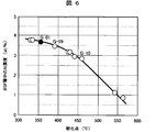
- It is a graph which shows the relationship between the softening point of a glass composition, and the aluminum concentration in a silicon substrate.
- LTCC Low Temperature Co-fired Ceramics
- the present inventor has found that when an electrode containing an oxide glass containing vanadium, phosphorus and boron is fired on a silicon substrate to form the electrode, both the performance and the reliability of the electronic component to which the silicon substrate is applied are improved.
- the glass does not contain lead. It has been clarified that the cell conversion efficiency can be improved to the same level as conventional lead oxide glass.
- the aluminum electrode containing an oxide glass containing vanadium, phosphorus and boron promotes the diffusion of aluminum to the silicon substrate while suppressing the diffusion of oxygen. It is considered that the cell conversion efficiency is improved by forming a good p + layer (Back Surface Field: BSF layer) which is good on the p-type semiconductor surface.
- BSF layer Back Surface Field
- the moisture resistance and water resistance reliability of the aluminum electrode which could not be achieved with lead oxide glass, can be improved at the same time, which also contributes to prolonging the life.
- the oxide glass containing vanadium, phosphorus and boron exhibits good wettability and reactivity with aluminum particles, and prevents the aluminum electrode from being corroded by water to form aluminum hydroxide.
- this glass is applied to an aluminum electrode, defects due to the generation of foreign matter from the aluminum electrode and irregularities can be reduced, which can also contribute to the improvement of the productivity of electronic parts such as solar cells.
- the adhesion of the aluminum electrode to the silicon substrate was good.
- the above-mentioned oxide glass of the present invention is further improved in weatherability by containing at least one of tellurium, antimony, bismuth and zinc, and the produced glass is crushed or the crushed glass particles are stored. It is advantageous to That is, the handleability of the glass particles is improved.
- the preferable composition range of the above-mentioned oxide glass is 40 to 80% by weight of V 2 O 5 , 10 to 25% by weight of P 2 O 5 , 5 to 15% by weight of B 2 O 3 in terms of the following oxide conversion 2 is 0-25% by weight, Sb 2 O 3 is 0-20% by weight, Bi 2 O 3 is 0-20% by weight, and ZnO is 0-20% by weight, and the amount of P 2 O 5 is B 2 O greater than 3 weight, yet the total amount of P 2 O 5, B 2 O 3 and TeO 2 is from 20 to 50 wt%.
- V 2 O 5 When V 2 O 5 is less than 40 wt%, the firing temperature of the aluminum electrode becomes high, adhesion and water resistance of the aluminum electrode is reduced. In a solar cell, conversion efficiency is reduced. On the other hand, if V 2 O 5 exceeds 80% by weight, crystallization tends to occur, and good softening and fluidity can not be obtained at low temperatures. In addition, the weather resistance of the glass itself is significantly deteriorated, and the workability is reduced when the glass is crushed or the crushed glass particles are handled. When P 2 O 5 is less than 10% by weight, crystallization tends to occur easily and good softening and fluidity can not be obtained. On the other hand, when it exceeds 25% by weight, the conversion efficiency of the solar cell tends to decrease.
- B 2 O 3 is less than 5% by weight, the conversion efficiency of the solar cell can not be improved, while if it exceeds 15% by weight, the conversion efficiency of the solar cell is lowered. Moreover, even if TeO 2 exceeded 25 weight%, the conversion efficiency of the photovoltaic cell fell.
- Sb 2 O 3 , Bi 2 O 3 and ZnO each exceed 20% by weight, the softening point of the glass may become high or crystallization may occur, so that it is difficult to obtain good softening fluidity at low temperatures. Become. Furthermore, when the amount of B 2 O 3 is larger than the amount of P 2 O 5 , the crystallization tendency is increased, and the conversion efficiency of the solar battery cell is reduced.
- the most effective glass composition range is 60 to 80% by weight of V 2 O 5 in terms of the following oxide, P 10 to 20% by weight of 2 O 5, 5 to 10% by weight of B 2 O 3 , 0 to 15% by weight of TeO 2 , 0 to 10% by weight of Sb 2 O 3 , 0 to 10% by weight of Bi 2 O 3 % And ZnO were 0-10 wt%, and the total amount of P 2 O 5 , B 2 O 3 and TeO 2 was 20-40 wt%.
- the content of glass in the aluminum electrode formed in the solar battery cell is preferably 0.2 to 2 parts by weight, less than 0.2 parts by weight, or 2 parts by weight with respect to 100 parts by weight of aluminum particles. Cell conversion efficiency decreased. However, when it develops to the electrode of electronic components other than a photovoltaic cell, glass can be contained to 15 weight part. If it exceeds 15 parts by weight, the electrical resistance of the aluminum electrode will increase.
- the softening point of the glass is 420 ° C. or less and the softening flowability at 500 ° C. is good, the reliability of the adhesion of the aluminum electrode to the substrate and the moisture resistance are high, and when applied to a solar battery cell. Showed a high conversion efficiency.
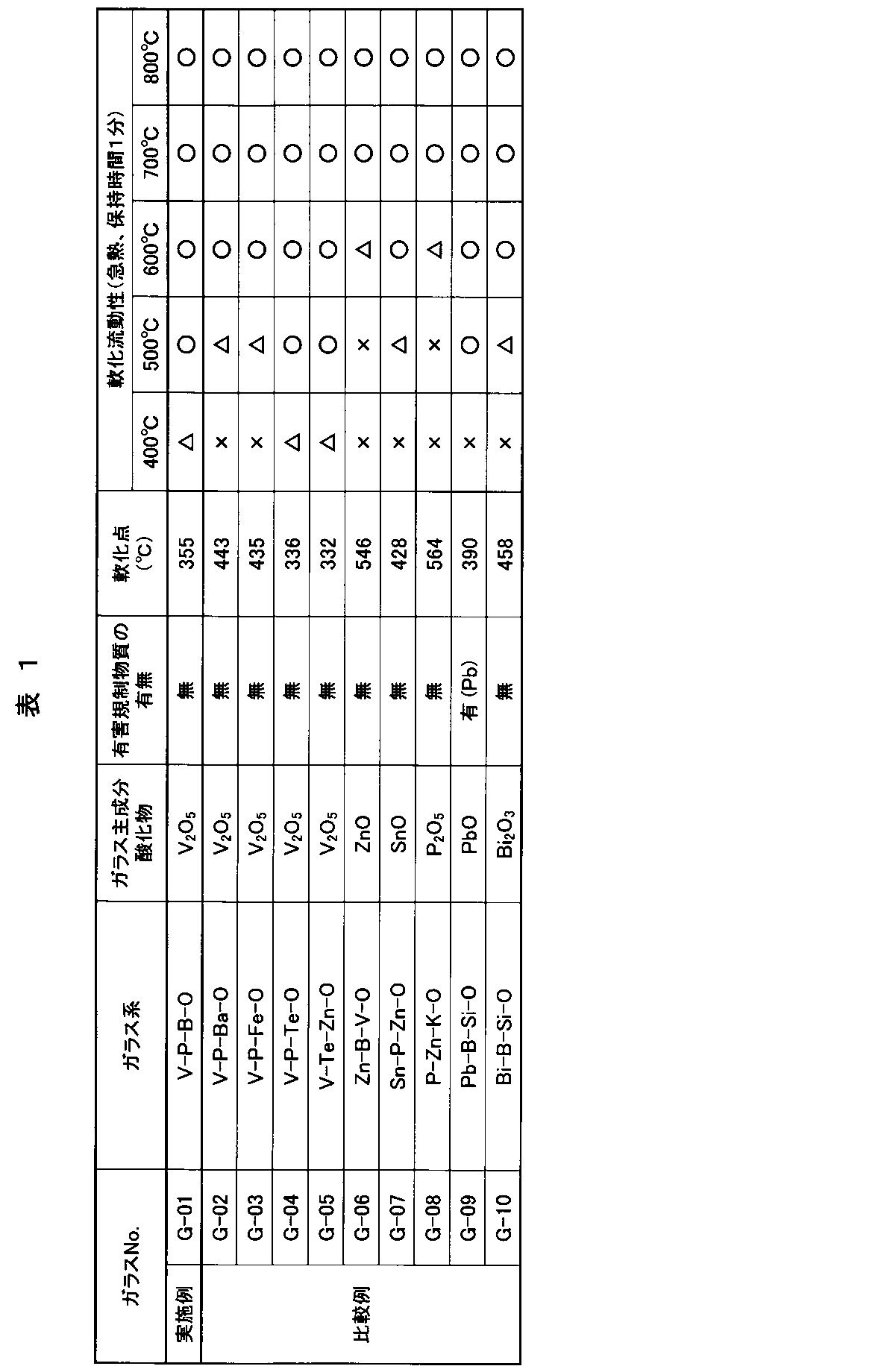
- Table 1 shows the glass system examined in this example, its main component oxide, and its characteristics.
- G-01 is the glass of the example
- G-02 to 10 are the glasses of the comparative example.
- the “presence or absence of a hazardously controlled substance” in Table 1 was judged based on whether the hazardous substance regulated by the RoHS directive or the Joint Industry Guide Line was included.
- the "softening point” was measured by differential thermal analysis (DTA) using each glass powder.
- the analysis temperature rising condition of DTA was 5 ° C./min in air.
- FIG. 1 shows an example of a typical glass DTA curve.
- the start temperature of the first endothermic peak is the transition point T g
- the peak temperature is the sag point M g
- the second endothermic peak temperature is the softening point T s
- the respective characteristic points are defined by the viscosity.
- M g is 10 11 poise
- T s corresponds to 10 7.65 poise.
- the "softening flowability" was evaluated by producing a green compact having a diameter of 10 mm and a thickness of 5 mm using each glass powder, and heating on an alumina substrate.
- the heating conditions were such that the green compact mounted on the alumina substrate was placed in an electric furnace held at 400 ° C., 500 ° C., 600 ° C., 700 ° C., and 800 ° C. in the air for 1 minute, respectively, and taken out.
- good fluidity was obtained by visual observation, "o”, good fluidity was not obtained, but when softened, " ⁇ ”, and as a green compact, softening was also possible. When it did not, it evaluated as "x".
- the glass containing the harmful regulatory substance is only G-09.
- This Pb-B-Si-O-based glass has been widely applied to various electrodes of electronic parts such as solar cells and plasma display panels.
- the softening point was also relatively low at 390 ° C., and the flowability at 500 to 800 ° C. was good.
- G-10 is Pb-free glass which has been widely studied and is beginning to be put into practical use.
- this Bi-B-Si-O-based glass does not contain any harmful regulatory substance, its softening point and softening flowability have been raised in temperature as compared to G-09.
- the glass with a softening point higher than G-10 is G-06 in the Zn-B-V-O system and G-08 in the P-Zn-K-O system, and the softening flowability is also increased.
- Glass with a softening point between G-09 and G-10, G-02 of the V-P-Ba-O system, G-03 of the V-P-Fe-O system and Sn-P-Zn-O Although it was G-07 of the system, the softening flowability was almost equivalent to G-10.
- Glass with a softening point lower than G-09 is G-01 for V-P-B-O, G-04 for V-P-Te-O, and G-05 for V-Te-Zn-O. And the softening flowability was also lowered.
- the electroconductive paste for aluminum electrodes was produced using each glass shown in Table 1, and conversion efficiency and environmental conservation were evaluated by mounting in a photovoltaic cell. In addition, the appearance, adhesion and water resistance of the formed aluminum electrodes were also evaluated.
- the conductive paste for aluminum electrodes was prepared for each of the glasses G-01 to G-10 in Table 1.
- the glass was crushed into particles of 3 ⁇ m or less by a stamp mill and a jet mill.
- the aluminum particles those having an average particle diameter of 3 ⁇ m prepared by the atomizing method are used, and with respect to 100 parts by weight of the aluminum particles, 0.4 parts by weight of the glass particles of G-01 to 08, G-09 and -10 In the case of glass particles, 0.7 parts by weight was mixed respectively.
- the reason for changing the mixing amount of the glass particles is that the specific gravity of the glass of G-09 and -10 was about twice as large as that of the glass of G-01-8, and the glass content was almost the same in volume ratio .
- a solvent in which 2% by weight of a binder resin had been dissolved in advance was added and kneaded to prepare a conductive paste for an aluminum electrode.
- ethyl cellulose was used as the binder resin
- ⁇ -terpineol was used as the solvent.
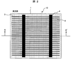
- FIG. 2 is a schematic plan view showing an example of a light receiving surface of a representative solar battery cell.
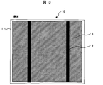
- 3 is a schematic plan view showing an example of the back surface,
- FIG. 4A is a schematic sectional view taken along the line AA 'in FIG. 2, and
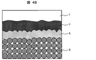
- FIG. 4B is an enlarged sectional schematic view in the vicinity of the back surface (shown by 4 in FIG. Part).
- a single crystal silicon substrate or a polycrystalline silicon substrate is usually used for the semiconductor substrate 1 of the solar battery cell 10 and contains boron or the like to be a p-type semiconductor. Irregularities are formed on the light receiving surface side by chemical etching or the like in order to suppress the reflection of sunlight.
- phosphorus or the like is doped on the light receiving surface to form an n-type semiconductor layer 2 having a thickness of about 1 ⁇ m. Then, a pn junction is formed at the boundary with the p-type bulk portion.
- an antireflective layer 3 such as silicon nitride is formed to a thickness of about 100 nm by vapor deposition or the like.
- a conductive paste for silver electrode containing silver particles and glass particles is used to form light receiving surface electrode 4 and output electrode 6, and aluminum containing aluminum particles and glass particles is used to form back surface electrode 5.
- Conductive pastes for electrodes are used. Each conductive paste is applied on the surface of the anti-reflection layer 3 formed on the light receiving surface of the semiconductor substrate 1 or the back surface of the semiconductor substrate 1 by a screen printing method or the like.
- the conductive paste After the conductive paste is dried, it is fired at around 800 ° C. in the atmosphere to form the respective electrodes.
- the glass composition contained in the light receiving surface electrode 4 reacts with the antireflective layer 3 to electrically connect the light receiving surface electrode 4 and the n-type semiconductor layer 2.
- the aluminum component in the back surface electrode 5 reacts with the semiconductor substrate 1 to form an alloy layer 8 of aluminum and silicon, and further aluminum diffuses into the semiconductor substrate 1 (Back Surface Field: BSF layer) ) 7 is formed.
- BSF layer 7 Back Surface Field: BSF layer 7
- the alloy layer 8 also has an effect of reflecting the light incident on the solar battery cell 10 on the back surface and confining the light in the semiconductor substrate 1 and is useful for improving the performance of the solar battery cell.
- the solar battery cell according to the electronic component of the present invention was produced.
- a p-type single crystal silicon substrate was used as the semiconductor substrate 1.
- the silicon substrate had a size of 125 mm square and a thickness of 200 ⁇ m.
- light reception of the semiconductor substrate 1 is performed using a strongly alkaline aqueous solution consisting of 1% caustic soda (sodium hydroxide: NaOH) and 10% isopropyl alcohol (CH 3 CH (OH) CH 3 ).
- the surface was etched to form asperities.
- a solution containing phosphorus pentoxide (P 2 O 5 ) is applied to the light receiving surface, and heat treatment is performed at 900 ° C. for 30 minutes to diffuse phosphorus (P) into the semiconductor substrate 1.
- Type semiconductor layer 2 was formed. After removing the phosphorus pentoxide, a silicon nitride film was uniformly formed on the n-type semiconductor layer 2 as an antireflective layer 3 with a thickness of about 100 nm.
- the silicon nitride film can be formed by a plasma CVD method using a mixed gas of silane (SiH 4 ) and ammonia (NH 3 ) as a raw material.
- a conductive paste for silver electrode containing silver particles and glass particles is applied in a grid shape by screen printing on the antireflection layer 3 and dried at 150 ° C. for 10 minutes I did.
- Silver particles having an average particle diameter of about 2 ⁇ m were used.
- glass particles a V-Ag-P-Te-O-based low melting glass having an average particle diameter of about 2 ⁇ m and containing no harmful lead was used.
- the same conductive paste for silver electrode as that described above was used for the output electrode 6 formed on the back surface of the semiconductor substrate 1, and it was similarly applied by screen printing and dried.
- a conductive paste for aluminum electrode containing aluminum particles and glass particles for the back electrode 5 was similarly applied and dried.
- the conductive paste for aluminum electrodes the conductive paste for aluminum electrodes produced using the example glass G-01 described above and the comparative glasses G-02 to 10 was used. Moreover, the conductive paste for aluminum electrodes which does not contain glass particles was also used for comparison.
- the solar cell 10 was manufactured by simultaneously firing and forming the light receiving surface electrode 4, the back surface electrode 5, and the output electrode 6 by rapidly heating to 800 ° C. in the atmosphere using a tunnel furnace and holding for 30 seconds. .
- the film thickness of the light-receiving surface electrode 4 and the output electrode 6 after firing was about 20 ⁇ m, and the film thickness of the back surface electrode was about 40 ⁇ m.
- the cell conversion efficiency was measured using the solar simulator with respect to the solar battery cell 10 which changed and produced the electrically conductive paste for aluminum electrodes for back surface electrodes 5 using a solar simulator.
- the produced photovoltaic cell 10 was also evaluated from the viewpoint of environmental protection (presence or absence of a harmful control substance). Furthermore, the appearance, adhesion and water resistance of the aluminum electrode formed for the back electrode 5 were also evaluated.
- the "adhesiveness" of the aluminum electrode was evaluated by the peel test.
- a commercially available cellophane tape is attached to an aluminum electrode, and when peeling off the aluminum electrode does not peel off, " ⁇ ", if slightly peeled off, “ ⁇ ”, if peeled off significantly It was set as “x” to.
- the "water resistance” is obtained by immersing the produced solar battery cell in warm water at 50 ° C. for 8 hours, " ⁇ ” when the aluminum electrode is hardly discolored in appearance, and " ⁇ when partially blackened”. When it was blackened on one side, it was evaluated as "x”.
- the above evaluation results are comprehensively examined and judged, “Good” for practically good solar cells, “Good” for insufficient solar cells, “good” for problematic solar cells It evaluated as x ".
- Example V-P-B-O-based glass G-01 and comparative example Pb-B-Si-O-based glass G-09 as a back surface electrode High conversion efficiency.
- comparative example Bi-B-Si-O-based glass G-10 relatively high conversion efficiency was shown. The conversion efficiency was lower when other glasses were used. Also, the conversion efficiency was lower when no glass was used than when using any glass.
- G-09 contains a large amount of harmful lead, so there are environmental problems even with solar cells, but there is no problem when using other glass.
- the solar cell with the highest conversion efficiency, ie, the highest performance electronic component was the case where the VPHO glass of Example G-01 was applied to the electrode.
- the appearance of the aluminum electrode formed in the solar battery cell was all good when using low melting point glass G-01 to 05 containing V 2 O 5 as the main component .
- the glass other than that was used and when it did not contain glass, many foreign materials and unevenness were recognized in the aluminum electrode surface part.
- the adhesion of the aluminum electrode was relatively low when the softening point was relatively low and glasses G-01 to 05, -07, -09 and -10 which softened and flowed at 500 ° C were used.
- the glass with good appearance, adhesion and water resistance of the aluminum electrode is G-01 to 05, and if it is a low melting point glass containing V 2 O 5 as the main component, it relates to the aluminum electrode It turned out that productivity and reliability can be improved or improved. It is considered that this is because low melting point glass particles containing aluminum particles and V 2 O 5 as main components have good wettability and reactivity when firing and forming an electrode. However, most of the low melting point glasses containing V 2 O 5 as a main component have reduced cell conversion efficiency. Only the oxide glass containing vanadium, phosphorus and boron of Example G-01 was the only glass whose cell conversion efficiency could be improved to the level of the Pb-B-Si-O-based glass G-09.
- the glass is substantially free of harmful controlled substances such as lead, and is sufficiently considered in the environment, and the conductive paste for electrodes to which the glass is applied, and the conductive paste Also in the electronic component having the formed electrode, the influence on the environmental load can be reduced.
- the lead content of electronic parts is regulated to 1000 ppm or less.
- the materials that make up the electronic component should not intentionally contain harmful lead.
- lead may be mixed as an impurity, and it is preferable to set the concentration to 1000 ppm or less as in the case of the electronic component also in each material constituting the electronic component.
- the V—P—B—O glass for an electrode according to the present invention has been developed on the premise of this in order to reduce the influence of environmental loads, and a conventional Pb—B—Si—O type glass or Bi—B— is used. It has been found that the performance and reliability of electronic parts can be improved compared to the case of using Si-O-based glass.
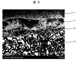
- Example 1 it was found that the conversion efficiency of the solar battery cell was different depending on the glass contained in the aluminum electrode. In order to investigate this cause, the state of the BSF layer 7 and the alloy layer 8 which are said to affect the cell conversion efficiency was observed and analyzed in detail by SEM-EDX.
- SEM-EDX The cross-sectional SEM photograph of the back surface vicinity of the photovoltaic cell produced using FIG. 5 using the electrically conductive paste for aluminum electrodes containing VPBO glass G-01 shown by Table 1 and Table 2 is shown. Since the BSF layer 7 is not usually observed, it was observed by etching using a hydrofluoric-nitric acid aqueous solution.
- the BSF layer 7 is formed by the diffusion of the aluminum component from the back electrode 5 to the semiconductor substrate 1 made of a silicon substrate.
- an alloy layer 8 is also formed between the back electrode 5 and the BSF layer 7 by the reaction of aluminum and silicon.
- glass G-02-10 other than G-01 was also made when using glass G-02-10 other than G-01.
- the compositions of the BSF layer 7 and the alloy layer 8 were analyzed by high sensitivity EDX.
- both aluminum and silicon were detected regardless of which glass was used.
- the composition of the analysis was very high, such as 90 atomic% or more of aluminum, while silicon was as low as 10 atomic% or less. The variation within this composition range is large even within the same solar battery cell, and a clear relationship between the conversion efficiency of the solar battery cell and the composition of the alloy layer 8 could not be found.
- the composition of the BSF layer 7 was similarly analyzed by high sensitivity EDX.
- a difference in the composition of the BSF layer 7 was observed depending on the glass.
- the relationship between the aluminum (Al) concentration in the BSF layer 7 and the softening point of the glass composition for aluminum electrodes is shown in FIG. It was found that the lower the softening point of the glass, the higher the aluminum concentration in the BSF layer 7. However, as shown in Tables 1 and 2, the higher the aluminum concentration, that is, the lower the softening point of the glass, the higher the conversion efficiency of the solar battery cell. Therefore, the oxygen concentration in the BSF layer 7 was also examined.
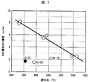
- FIG. 7 shows the relationship between the oxygen (O) concentration in the BSF layer 7 and the softening point of the glass composition for an aluminum electrode.
- the VPHO glass G-01 of the example With regard to the Pb-B-Si-O-based glass G-09 and the Bi-B-Si-O-based glass G-10 of the comparative example, this tendency is not met, and even if the softening point is low, the oxygen concentration in the BSF layer 7 is It was low. That is, it can be said that these glasses are difficult to oxidize the silicon substrate.
- the glass composition for aluminum electrodes which can make the aluminum concentration of BSF layer 7 high, and can make oxygen concentration low can improve the conversion efficiency of a photovoltaic cell.
- the softening point of the glass composition contained in the electrode may be lowered.
- the Pb-B-Si-O-based glass G-09 and the Bi-B-Si-O-based glass G-10 of the comparative example are very easy to be reduced, they are easily reduced in the aluminum electrode and oxygen is deprived. It is believed that the silicon substrate did not reach to oxidize the silicon substrate. As evidence of this, when X-ray diffraction of the back electrode 5 containing G-09 and -10, respectively, precipitation of lead metal and metal bismuth was observed. This is the result of the G-09 and -10 glasses being reduced in the aluminum electrode and deposited from these glasses.
- Low-melting glass G-02 to 05 containing V 2 O 5 as the main component is difficult to reduce compared to G-09 and -10, and such an effect can not be obtained, so it is thought that it is easy to oxidize the silicon substrate Be
- the V-P-B-O-based glass G-01 of the example is also a low melting point glass having V 2 O 5 as a main component, similarly to G-02 to 05 of the comparative example.
- the oxidation of the silicon substrate was suppressed. This is because G-01 and G-02 to 05 have different glass structures.
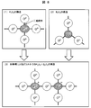
- the state of P 2 O 5 and B 2 O 3 in the glass structure is schematically shown in FIG.
- P 2 O 5 has one double bond oxygen (O) to one phosphorus (P) as shown in FIG. 8 (1) in the glass structure, and three crosslink oxygen (O) s make the glass It forms a mesh structure.
- B 2 O 3 forms a glass network structure from three bridging oxygen (O) to one boron (B) as shown in FIG. 8 (2) in the glass structure.
- This phenomenon was adopted in the glass structure of the V-P-B-O-based low melting point glass G-01 of the example. This suppressed the diffusion of oxygen to the silicon substrate, that is, the oxidation of the silicon substrate. Needless to say, this is a technology that can be effectively used other than the aluminum electrode if it is an electrode formed on a silicon substrate. In addition, the softening point is lowered by using V 2 O 5 as the main component, so that the amount of aluminum diffusion to the silicon substrate can be increased. Thus, the conversion efficiency of the solar cell was improved by the decrease of the amount of oxygen diffusion to the silicon substrate and the increase of the amount of aluminum diffusion.
- the solar battery cell has been described as an example, it is a technology that can be applied to all electronic components using a silicon substrate.
- the glass is a low melting point glass containing V 2 O 5 as a main component, it is possible to reduce the rate of defects such as the appearance of the aluminum electrode, and to improve the reliability such as adhesion and moisture resistance. This is due to the wettability and reaction with aluminum, and it goes without saying that the same effect can be obtained also with an aluminum alloy containing aluminum as a main component.
- the example applied to the back surface electrode of a photovoltaic cell was demonstrated, it can not be overemphasized that it is applicable also to the aluminum electrode and aluminum alloy electrode of other electronic components.
- Table 3 shows the composition and characteristics of the prepared VPOB low-melting glass. The glass production method of GA-01 to 30 shown in Table 3 will be described.
- the oxide shown by the composition of Table 3 was made into the glass raw material, and 200 g of each was mix
- the produced glass was ground by a stamp mill and a jet mill to an average particle size of 1 to 2 ⁇ m to obtain respective glass particles.
- the density of the produced glass was measured by the Archimedes method, and the softening point and the softening flowability were evaluated in the same manner as in Example 1.
- the density of the prepared V-P-B-O type low melting glass GA-01 to 30 is in the range of 2.60 to 3.60 g / cm 3 , and the conventional Pb-B-Si-O type low melting point The density was about half that of the glass G-09 and the Bi-B-Si-O low melting point glass G-10.
- the glass having a low density was GA-27 to 30, and the content of P 2 O 5 was equal to or less than that of B 2 O 3 .
- the content of P 2 O 5 was increased about twice as much as the content of B 2 O 3 to try to actively utilize the boric acid abnormal phenomenon described in Example 2.
- glasses having a high density were GA-15, -22 to 24 and -26 containing 30% by weight or more of TeO 2 .
- the softening point tends to be lower as the content of V 2 O 5 or TeO 2 is higher and the amount of P 2 O 5 is lower.
- the softening flowability was that all glasses had good flowability at 600 ° C. or higher. At 500 ° C., except for GA-27, -28 and -30, it had good fluidity. Also, at 400 ° C, GA-05 to 07, -09, -13 and -16 softened, and only GA-01 to 04, -14, -15, -22 and -23 showed good fluidity. . Similar to the softening point, the glass having a larger content of V 2 O 5 and TeO 2 and a smaller amount of P 2 O 5 tends to have a better softening flow at a low temperature.
- a conductive paste for an aluminum electrode was produced in the same manner as in Example 1 using the glass particles of GA-01 to 30. However, nitrocellulose was used as the binder resin, and butyl carbitol acetate was used as the solvent. Further, for comparison, in the same manner as in Example 1, the conductivity for aluminum electrodes containing Pb-B-Si-O low melting point glass G-09 and Bi-B-Si-O low melting point glass G-10 respectively A paste and a conductive paste for aluminum electrode without glass were also prepared.
- the solar cell shown in FIGS. 2 to 4 was produced and evaluated in the same manner as in Example 1 using the produced conductive paste for an aluminum electrode.
- the semiconductor substrate 1 a 150 mm square p-type polycrystalline silicon substrate having a thickness of 200 ⁇ m was used. Table 4 shows the evaluation results of the manufactured solar battery cell.
- a polycrystalline silicon substrate having a cell conversion efficiency lower than that of a single crystal silicon substrate is used as the semiconductor substrate 1 and therefore very high as a polycrystalline silicon substrate.
- Conversion efficiency 17.0% or more “ ⁇ ”, 16.5 to 17.0% “ ⁇ ”, 16.0 to 16.5% “ ⁇ ”, less than 16.0% “X” did.
- Other evaluations were performed in the same manner as in Example 1. However, in the “overall evaluation”, the solar cell that was particularly excellent in conversion efficiency in the “o” evaluation was evaluated as “o”.
- the glass composition for an aluminum electrode may contain one or more of Te, Sb, Bi, and Zn based on the VPBO system. .
- Te, Sb, Bi, and Zn the weather resistance of the glass is improved, and the handleability of the glass particles until the production of the conductive paste for an aluminum electrode is improved.
- the overall evaluation of the solar battery cell is 40 to 80 wt% of V 2 O 5 , 10 to 25 wt% of P 2 O 5 , and B 2 O 3 in terms of the following oxides. 5 to 15% by weight, 0 to 25% by weight of TeO 2 , 0 to 20% by weight of Sb 2 O 3 , 0 to 20% by weight of Bi 2 O 3 , and 0 to 20% by weight of ZnO, P 2
- the amount of O 5 was larger than the amount of B 2 O 3 , and the total amount of P 2 O 5 , B 2 O 3 and TeO 2 was 20 to 50% by weight.
- V-P-B-O type low melting glass having a density of 2.81 to 3.25 g / cm 3 , a softening point of 420 ° C. or less, and a good fluidity at 500 ° C. It is mentioned that it is effective.
- the overall evaluated glass composition range of “ ⁇ ” was 60 to 80 wt% of V 2 O 5 , 10 to 20 wt% of P 2 O 5 , B 2 O 3 in terms of the following oxides.
- the glass composition for aluminum electrodes in the above composition range can promote the diffusion of the aluminum component to the silicon substrate and can suppress the diffusion of oxygen, so it is effective not only for solar cells but also for all electronic components using silicon substrates. It goes without saying that it can be applied to Moreover, although it is effective especially to an aluminum electrode, it can utilize also other than an aluminum electrode.
- the effect of the content of the V—P—B—O low-melting glass in the aluminum electrode on the conversion efficiency of the solar battery cell was examined in detail.
- GA-05 in Example 3 shown in Table 3 and Table 4 was used as this glass.
- the glass content of GA-05 was examined in the range of 0 to 5 parts by weight with respect to 100 parts by weight of aluminum particles (0, 0.2, 0.4, 0.7, 1.0, 1.5, 2 .0, 2.5, 3.0, 3.5, 4.0 and 5.0 parts by weight).
- Example 3 In the same manner as in Example 3, the glass content was changed, and 12 types of conductive pastes for aluminum electrodes were produced.
- the solar cell shown in FIG. 2, FIG. 3, FIG. 4A and FIG. 4B was produced like Example 3 using the produced electrically conductive paste for aluminum electrodes for the back surface electrode, and cell conversion efficiency was measured.
- FIG. 9 shows the relationship between the conversion efficiency of the solar battery cell and the content of the V—P—B—O glass composition contained in the aluminum electrode. When glass was not contained in the aluminum electrode which is the back surface electrode, the conversion efficiency of the solar cell was extremely low, but when only 0.2 parts by weight of GA-05 glass was contained, the conversion efficiency was improved at once.
- a very high conversion efficiency of 17% or more was obtained in the range of 0.2 to 0.7 parts by weight of GA-05 glass. At a higher content, the conversion efficiency decreased slightly to 2 parts by weight, but the conversion efficiency was as good as 16.5% or more. When the amount exceeds 2 parts by weight, the conversion efficiency is significantly reduced, and at 2.5 parts by weight or more, it falls below 16.0%.
- the reason why the conversion efficiency decreases with the glass content in the aluminum electrode is considered to be the increase in the diffusion amount of oxygen to the silicon substrate, that is, the progress of the oxidation of the silicon substrate.
- the content of the V—P—B—O low-melting glass in the aluminum electrode applied as the back electrode of the solar battery cell was preferably in the range of 0.2 to 2 parts by weight.
- the range of 0.2 to 0.7 parts by weight was effective.
- this can be effectively applied not only to solar cells but also to electronic components in general using a silicon substrate.
- it is effective especially to an aluminum electrode, it can not be overemphasized that it can utilize also except an aluminum electrode.
- the glass content of GA-09 was examined in the range of 0 to 25 parts by weight with respect to 100 parts by weight of aluminum alloy particles (0, 0.2, 2.0, 5.0, 10.0, 15.0, 20.0 and 25.0 parts by weight).
- Example 3 Eight kinds of conductive pastes for aluminum alloy electrodes were prepared by changing the glass content. However, ethyl cellulose was used in place of nitrocellulose as the binder resin. The solvent is butyl carbitol acetate.
- the prepared conductive paste for an aluminum alloy electrode was applied to a single crystal silicon substrate by screen printing and dried at 150 ° C. for 10 minutes. Then, it was put into an electric furnace, heated to 500 ° C. at a temperature rising rate of 10 ° C./minute in the atmosphere, and held for 10 minutes, and then the furnace was cooled. The film thickness of the aluminum alloy electrode was about 20 ⁇ m. The specific resistance of the aluminum alloy electrode formed on the silicon substrate was measured by the four-point probe method.
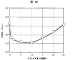
- FIG. 10 shows the relationship between the specific resistance of the aluminum alloy electrode and the content of the glass composition contained in the electrode.
- the specific resistance is extremely high, but when only 0.2 parts by weight of GA-09 glass is contained, the specific resistance decreases rapidly. did.
- the specific resistance on the order of 10 -5 ⁇ cm was achieved in the range of 0.2 to 15 parts by weight of GA-05 glass. At a content of 20 parts by weight or more, the specific resistance of the aluminum alloy electrode became large again.
- the content of the V—P—B—O low melting point glass in the electrode is 0.2 It has been found that a range of ⁇ 15 parts by weight is preferred.
- a V—P—B—O low melting point glass was examined in the aluminum alloy electrode, but it goes without saying that it can be used for an aluminum electrode and other electrodes.
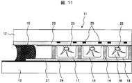
- FIG. 11 is a schematic cross-sectional view showing an example of a plasma display panel. This will be described below with reference to FIG.
- the front plate 12 and the back plate 13 are disposed to face each other with a gap of 100 to 150 ⁇ m, and the gap between the substrates (the front plate 12 and the back plate 13) is maintained by the partition wall.
- the peripheral portions of the front plate 12 and the back plate 13 are airtightly sealed with a sealing material 15, and the inside of the panel is filled with a rare gas.
- a display electrode 20 is formed on the front plate 12, a dielectric layer 23 is formed on the display electrode 20, and a protective layer 25 (eg, MgO) for protecting the display electrode 20 and the like from discharge on the dielectric layer 23.
- the partition 14 is made of a structure obtained by sintering a material containing at least a glass composition and a filler at 500 to 600 ° C., and is usually a stripe or box structure. Further, the address electrodes 21 of the back plate 13 are formed to be orthogonal to the display electrodes 20 of the front plate 12.
- the minute space (cell 16) partitioned by the partition 14 is filled with a fluorescent substance.
- the phosphor in the cell 16 is formed by filling the paste for the phosphor into the cell 16 and baking it at 450 to 500.degree.
- One pixel is constituted by three color cells of a cell filled with the red phosphor 17, a cell filled with the green phosphor 18, and a cell filled with the blue phosphor 19. Each pixel emits various colors in accordance with the signal applied to the display electrode 20 and the address electrode 21.
- the sealing material 15 is previously applied to the periphery of either the front plate 12 or the back plate 13 by a dispenser method, a printing method, or the like.
- the applied sealing material 15 may be pre-fired simultaneously with the firing of the phosphors 17-19.
- By temporarily baking the applied sealing material air bubbles in the glass sealing portion can be remarkably reduced, and a highly reliable (that is, highly airtight) glass sealing portion can be obtained.
- the sealing of the front plate 12 and the back plate 13 is performed by arranging the front plate 12 and the back plate 13 separately manufactured to face each other with accurate alignment and heating to 420 to 500.degree. At this time, the gas in the cell 16 is exhausted while heating, and a noble gas is filled instead, thereby completing the plasma display panel as an electronic component.
- the sealing material 15 may be in direct contact with the display electrode 20 or the address electrode 21 at the time of pre-sintering of the sealing material or at the time of glass sealing, the electrode wiring material and the sealing material do not react chemically. It is important that it is configured.
- a voltage is applied between the display electrode 20 and the address electrode 21 of the cell 16 to be lighted to perform address discharge in the cell 16 to plasma rare gas It excites to the state and accumulates the wall charge in the cell.
- display discharge occurs only in the cells in which the wall charges are accumulated, and ultraviolet light 22 is generated.
- image information is displayed by causing the fluorescent materials 17 to 19 to emit light using the ultraviolet light 22.
- the display electrode 20 and the address electrode 21 a silver thick film electrode wiring has been conventionally used in consideration of good electrical properties and oxidation resistance during manufacturing.
- the formation of the display electrodes 20 and the address electrodes 21 can also be performed by a sputtering method, but the printing method is advantageous for reducing the manufacturing cost.
- the dielectric layers 23 and 24 are usually formed by printing. Further, the display electrode 20, the address electrode 21 and the dielectric layers 23, 24 formed by the printing method are generally fired at a temperature range of 550 to 620 ° C. in an oxidizing atmosphere.
- the silver thick film electrode wiring has a problem that silver is apt to cause a migration phenomenon and also has a problem that the material cost is high.
- the specific resistance of the electrode wiring is low, the chemical reaction between the electrode wiring and the dielectric layer does not occur, and the vicinity of the formed electrode wiring It is necessary to satisfy the condition that the air pressure (air bubbles etc.) is generated and the electrical pressure resistance does not decrease.
- the aluminum alloy particles (Al-10 wt% Ag) used in Example 5 were prepared as metal particles to be contained in the conductive paste for aluminum electrode.
- a binder resin and a solvent were added and mixed to prepare a conductive paste for aluminum electrode.
- ethyl cellulose was used as a binder resin
- ⁇ -terpineol was used as a solvent.
- the plasma display panel according to the present invention was produced.
- the conductive paste for an aluminum electrode was applied to the entire surface of the front plate 12 and the back plate 13 by screen printing, and dried at 150 ° C. in the atmosphere. Excess portions of the coating film were removed by photolithography to pattern the electrode wiring, and then baked in the air at 580 ° C. for 10 minutes to form the display electrode 20 and the address electrode 21.
- dielectric layers 23 and 24 were respectively applied and baked at 560 ° C. for 30 minutes in the air.
- the front plate 12 and the back plate 13 produced in this manner were disposed opposite to each other, and the outer edge was sealed with glass to fabricate a plasma display panel having a structure as shown in FIG.
- the electrode wiring (the display electrode 20 and the address electrode 21) formed by using the conductive paste for aluminum electrode according to the present invention includes the interface between the display electrode 20 and the dielectric layer 23, the address electrode 21 and the dielectric layer 24. No generation of voids was observed at the interface of the above, and the plasma display panel could be manufactured in a good appearance.
- the conductive paste for an aluminum electrode of the present invention can be applied as an electrode wiring of a plasma display panel. Moreover, since it can be an alternative to expensive silver thick film electrode wiring, it can greatly contribute to cost reduction.
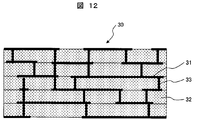
- FIG. 12 is a schematic cross-sectional view showing a structural example before firing of a multilayer wiring board (five layers) of LTCC (Low Temperature Co-fired Ceramics).
- the multilayer wiring board 30 is a wiring board on which wiring (conductive paste 31 for wiring) is three-dimensionally formed. This will be described below with reference to FIG.
- the production of a multilayer wiring board is usually performed in the following procedure.
- a green sheet 32 containing glass powder, ceramic powder and a binder is prepared, and the through holes 33 are opened at desired positions.
- the conductive paste 31 for wiring is applied to a desired wiring pattern by a printing method on the green sheet 32 in which the through holes 33 are opened, and the through holes 33 are also filled. If necessary, the wiring conductive paste 31 is applied to the back surface of the green sheet 32 by a printing method. When applying on the back surface of the green sheet 32, it is performed after drying the conductive paste 31 for wiring applied on the surface.
- a plurality of green sheets 32 on which a predetermined wiring pattern is formed are stacked and integrally fired to manufacture an LTCC multilayer wiring board.
- atmosphere is common.
- a conductive paste for wiring a conductive paste of silver is usually used in consideration of good electrical properties and oxidation resistance during production.
- the glass phase is easily softened / flows at the portion where the green sheet 32 and the conductive paste 31 are in contact during firing, the copper particles are oxidized, and the specific resistance of the electrode wiring is There was an increasing problem. Furthermore, a void may be generated at the interface due to a chemical reaction with the glass phase.
- a multilayer wiring board according to the present invention was produced.
- the conductive paste 31 for wiring the conductive paste for aluminum electrode examined in Example 6 is used to form a multilayer wiring stack as shown in FIG. Bake for 30 minutes.
- SYMBOLS 10 Solar cell, 1 ... p-type semiconductor substrate, 2 ... n-type semiconductor layer, 3 ... anti-reflective layer, 4 ... light-receiving surface electrode, 5 ... back surface electrode, 6 ... output electrode, 7 ... BSF layer, 8 ... alloy Layers 11 Plasma display panel 12 Front plate 13 Rear plate 14 Partition wall 15 Sealing material 16 Cell 17 Red phosphor 18 Green phosphor 19 Blue phosphor Reference Signs List 20 display electrode 21 address electrode 22 ultraviolet light 23 24 dielectric layer 25 protective layer 30 multilayer wiring board 31 conductive paste for wiring 32 green sheet 33 through hole .
Landscapes
- Chemical & Material Sciences (AREA)
- Materials Engineering (AREA)
- Engineering & Computer Science (AREA)
- Chemical Kinetics & Catalysis (AREA)
- General Chemical & Material Sciences (AREA)
- Geochemistry & Mineralogy (AREA)
- Life Sciences & Earth Sciences (AREA)
- Organic Chemistry (AREA)
- Physics & Mathematics (AREA)
- Dispersion Chemistry (AREA)
- Spectroscopy & Molecular Physics (AREA)
- Glass Compositions (AREA)
- Photovoltaic Devices (AREA)
- Conductive Materials (AREA)
- Gas-Filled Discharge Tubes (AREA)
Abstract
本発明は、シリコン基板を用いた太陽電池セル等の電子部品の高性能化と高信頼化を達成できるアルミニウム電極用導電性ペースト及びそれに含有するガラス組成物、並びにそれらにより性能と信頼性が向上した電子部品を提供する。本発明によるアルミニウム電極用導電性ペーストは、アルミニウム電極にV-P-B-O系低融点ガラスを含有することによって、シリコン基板へのアルミニウム拡散量を増加でき、一方酸素拡散量を減少できるため、電子部品を高性能化できる。また、このガラスとアルミニウムが良好なぬれ性、反応性を有するため、電極の信頼性を向上できる。
Description
本発明は、シリコン基板に形成されるアルミニウム電極用導電性ペースト、それに含有されるアルミニウム電極用ガラス組成物、及びそのアルミニウム電極用導電性ペーストを用いて製造した電子部品に関する。
pn接合を有するシリコン基板を用いた太陽電池セル等の電子部品では、銀電極やアルミニウム電極が形成されている。これらの電極は、銀やアルミニウムの金属粒子を多数含む導電性ペーストを塗布、乾燥、焼成することによってシリコン基板等に形成される。通常、この導電性ペーストは、その金属粒子を主とし、ガラス粒子、バインダー樹脂及び溶剤等から構成される。電極焼成時には、導電性ペースト中のガラス粒子の軟化点以上に加熱することによって、そのガラス粒子が軟化流動し緻密な電極が形成されるとともに、基板等に強固に密着する。
このガラス粒子には、低温で軟化流動する、酸化鉛を主成分とする低融点ガラスが従来から使用されている。しかし、そのガラスに含まれる鉛は、RoHS指令等で規制されている有害物質であり、環境負荷への影響を低減するため、すなわち生態系の保全を図るために、太陽電池セルやプラズマディスプレイパネル等の電子部品では、鉛フリーの低融点ガラスが電極形成に適用されるようになってきた。たとえば、特許文献1では、太陽電池セルに形成される銀電極やアルミニウム電極に酸化ビスマスと酸化シリコンを含む鉛フリー低融点ガラスが提案されている。また、特許文献2では、酸化ビスマスと酸化ホウ素を含む低融点ガラスが提案されている。
特にアルミニウム粒子やアルミニウム合金粒子等の金属粒子を主体とした導電性ペーストは、その金属粒子表面の酸化皮膜により緻密に焼成できず、低抵抗化に問題点が存在していた。この点については、導電性ペースト中に、バナジウムや酸化バナジウムの粒子を添加することで、金属粒子の焼結性を改善し、低抵抗化させる手法が提案されている(特許文献3)。また、炭素、ゲルマニウム、スズ、水素化金属化合物及びリン化金属化合物等を添加することで耐酸化性を向上し、低抵抗化させる手法等も提案されている(特許文献4)。
一方で、太陽電池セル等に代表されるように、発電効率や寿命の向上が強く要求される電子部品においては、上記特許文献1~4の電極は、電子部品の性能と信頼性の両方を向上するに当たり、決して十分に配慮されたものではなかった。
pn接合を有するシリコン基板を用いた太陽電池セル等の電子部品では、n型半導体側には銀電極、p型半導体側にはアルミニウム電極が適用されることが多い。これらの電極に従来の酸化鉛を主成分とする低融点ガラスを用いると、太陽電池セルの発電効率、すなわち変換効率が高いが、特許文献1や2で提案されている鉛フリー低融点ガラスを使用すると、その変換効率が低下してしまう問題がある。これは、電極の焼結状態やシリコン基板との界面状態が影響されているものと考えられる。また、寿命等の信頼性に関しては、従来の酸化鉛を主成分とする低融点ガラスや、特許文献1~4で提案された材料や方法では改良が難しい。特にアルミニウム電極においては、水分によって、徐々に腐食され、水酸化アルミニウムが生成して、電極性能が劣化してしまう。
そこで、本発明の目的は、上記問題を鑑み、pn接合を有するシリコン基板を用いた太陽電池セル等の電子部品の高性能化と高信頼化の両方を同時に達成することである。また、これらを同時に達成することができるアルミニウム電極用導電性ペースト及びそれに適用するアルミニウム電極用ガラス組成物を提供することにある。
本発明の課題を解決する手段は以下のとおりである。
(1)金属粒子と、ガラス相とを有する電極がシリコン基板に形成された電子部品であって、該ガラス相がバナジウム、リン及びホウ素を含む酸化物ガラスであることを特徴とする電子部品。
(2)上記(1)において、前記ガラス相が次の酸化物換算でV2O5が60~80重量%、P2O5が10~25重量%、B2O3が5~15重量%を含み、P2O5量がB2O3量より多いことを特徴とする電子部品。
(3)上記(1)又は(2)において、前記ガラス相が次の酸化物換算でV2O5が70~80重量%、P2O5が10~20重量%、B2O3が5~10重量%、P2O5、B2O3の合計量がガラス相の20~40重量%であることを特徴とする電子部品。
(4)上記(1)において、前記ガラス相がさらにテルル、アンチモン、ビスマス及び亜鉛のうち1種以上を含むことを特徴とする電子部品。
(5)上記(4)において、前記ガラス相が次の酸化物換算でV2O5が40~80重量%、P2O5が10~25重量%、B2O3が5~15重量%、TeO2が0~25重量%、Sb2O3が0~20重量%、Bi2O3が0~20重量%、及びZnOが0~20重量%であり、P2O5量がB2O3量より多く、しかもP2O5、B2O3及びTeO2の合計量がガラス相の20~50重量%であることを特徴とする電子部品。
(6)上記(4)又は(5)において、前記ガラス相が次の酸化物換算でV2O5が60~80重量%、P2O5が10~20重量%、B2O3が5~10重量%、TeO2が0~15重量%、Sb2O3が0~10重量%、Bi2O3が0~10重量%、及びZnOが0~10重量%であり、P2O5、B2O3及びTeO2の合計量がガラス相の20~40重量%であることを特徴とする電子部品。
(7)上記(1)ないし(6)のいずれかにおいて、前記金属粒子の100重量部に対して前記ガラス相が0.2~2重量部の割合で含有されていることを特徴とする電子部品。
(8)上記(1)ないし(7)のいずれかにおいて、前記金属粒子がアルミニウム或いはアルミニウム合金であり、かつ前記シリコン基板がp型半導体を有し、該p型半導体に前記電極が形成されていることを特徴とする電子部品。
(9)上記(1)から(8)のいずれかにおいて、前記シリコン基板がpn接合を有する太陽電池セルであることを特徴とする電子部品。
(10)上記(1)ないし(9)のいずれかにおいて、前記アルミニウム電極用ガラス組成物の鉛の含有量が1000ppm以下であることを特徴とする電子部品。
(11)アルミニウム或いはアルミニウム合金からなる金属粒子と、ガラス粒子が、バインダー樹脂が溶解した溶剤中に分散したアルミニウム電極用導電性ペーストであって、該ガラス粒子がバナジウム、リン及びホウ素を含む酸化物ガラスであることを特徴とするアルミニウム電極用導電性ペースト。
(12)上記(11)において、前記ガラス粒子が次の酸化物換算でV2O5が60~80重量%、P2O5が10~25重量%、B2O3が5~15重量%を含み、P2O5量がB2O3量より多いことを特徴とするアルミニウム電極用導電性ペースト。
(13)上記(11)において、前記ガラス粒子が次の酸化物換算でV2O5が70~80重量%、P2O5が10~20重量%、B2O3が5~10重量%を含み、P2O5量がB2O3量より多いことを特徴とするアルミニウム電極用導電性ペースト。
(14)上記(12)又は(13)において、前記ガラス粒子がさらにテルル、アンチモン、ビスマス及び亜鉛のうち1種以上を含むことを特徴とするアルミニウム電極用導電性ペースト。
(15)上記(14)において、前記ガラス粒子が次の酸化物換算でV2O5が40~80重量%、P2O5が10~25重量%、B2O3が5~15重量%、TeO2が0~25重量%、Sb2O3が0~20重量%、Bi2O3が0~20重量%、及びZnOが0~20重量%であり、P2O5量がB2O3量より多く、しかもP2O5、B2O3及びTeO2の合計量がガラス相の20~50重量%であることを特徴とするアルミニウム電極用導電性ペースト。
(16)上記(14)において、前記ガラス粒子が次の酸化物換算でV2O5が60~80重量%、P2O5が10~20重量%、B2O3が5~10重量%、TeO2が0~15重量%、Sb2O3が0~10重量%、Bi2O3が0~10重量%、及びZnOが0~10重量%であり、P2O5、B2O3及びTeO2の合計量が20~40重量%であることを特徴とするアルミニウム電極用導電性ペースト。
(17)上記(11)ないし(15)のいずれかにおいて、前記ガラス粒子が前記金属粒子の100重量部に対して0.2~15重量部の割合で含有されていることを特徴とするアルミニウム電極用導電性ペースト。
(18)上記(11)ないし(15)のいずれかにおいて、前記ガラス粒子が前記金属粒子の100重量部に対して0.2~2重量部の割合で含有されていることを特徴とするアルミニウム電極用導電性ペースト。
(19)上記(11)ないし(18)のいずれかにおいて、前記アルミニウム電極用ガラス組成物の鉛の含有量が1000ppm以下であることを特徴とするアルミニウム電極用導電性ペースト。
(20)アルミニウム又はアルミニウム合金粉末を含有するアルミニウム電極に含まれるガラス組成物であって、該ガラス組成物がバナジウム、リン及びホウ素を含み、さらにテルル、アンチモン、ビスマス及び亜鉛のうち1種以上を含む酸化物ガラスであり、軟化点が420℃以下で、500℃で流動することを特徴とするアルミニウム電極用ガラス組成物。
(21)上記(20)において、前記アルミニウム電極用ガラス組成物が、酸化物換算でV2O5が40~80重量%、P2O5が10~25重量%、B2O3が5~15重量%、TeO2が0~25重量%、Sb2O3が0~20重量%、Bi2O3が0~20重量%、及びZnOが0~20重量%であり、P2O5量がB2O3量より多く、かつP2O5、B2O3及びTeO2の合計量が20~50重量%であることを特徴とするアルミニウム電極用ガラス組成物。
(22)上記(20)において、前記アルミニウム電極用ガラス組成物が次の酸化物換算でV2O5が60~80重量%、P2O5が10~20重量%、B2O3が5~10重量%、TeO2が0~15重量%、Sb2O3が0~10重量%、Bi2O3が0~10重量%、及びZnOが0~10重量%であり、P2O5、B2O3及びTeO2の合計量が20~40重量%であることを特徴とするアルミニウム電極用ガラス組成物。
(23)上記(20)ないし(22)のいずれかにおいて、前記アルミニウム電極用ガラス組成物の鉛の含有量が1000ppm以下であることを特徴とするアルミニウム電極用ガラス組成物。
(1)金属粒子と、ガラス相とを有する電極がシリコン基板に形成された電子部品であって、該ガラス相がバナジウム、リン及びホウ素を含む酸化物ガラスであることを特徴とする電子部品。
(2)上記(1)において、前記ガラス相が次の酸化物換算でV2O5が60~80重量%、P2O5が10~25重量%、B2O3が5~15重量%を含み、P2O5量がB2O3量より多いことを特徴とする電子部品。
(3)上記(1)又は(2)において、前記ガラス相が次の酸化物換算でV2O5が70~80重量%、P2O5が10~20重量%、B2O3が5~10重量%、P2O5、B2O3の合計量がガラス相の20~40重量%であることを特徴とする電子部品。
(4)上記(1)において、前記ガラス相がさらにテルル、アンチモン、ビスマス及び亜鉛のうち1種以上を含むことを特徴とする電子部品。
(5)上記(4)において、前記ガラス相が次の酸化物換算でV2O5が40~80重量%、P2O5が10~25重量%、B2O3が5~15重量%、TeO2が0~25重量%、Sb2O3が0~20重量%、Bi2O3が0~20重量%、及びZnOが0~20重量%であり、P2O5量がB2O3量より多く、しかもP2O5、B2O3及びTeO2の合計量がガラス相の20~50重量%であることを特徴とする電子部品。
(6)上記(4)又は(5)において、前記ガラス相が次の酸化物換算でV2O5が60~80重量%、P2O5が10~20重量%、B2O3が5~10重量%、TeO2が0~15重量%、Sb2O3が0~10重量%、Bi2O3が0~10重量%、及びZnOが0~10重量%であり、P2O5、B2O3及びTeO2の合計量がガラス相の20~40重量%であることを特徴とする電子部品。
(7)上記(1)ないし(6)のいずれかにおいて、前記金属粒子の100重量部に対して前記ガラス相が0.2~2重量部の割合で含有されていることを特徴とする電子部品。
(8)上記(1)ないし(7)のいずれかにおいて、前記金属粒子がアルミニウム或いはアルミニウム合金であり、かつ前記シリコン基板がp型半導体を有し、該p型半導体に前記電極が形成されていることを特徴とする電子部品。
(9)上記(1)から(8)のいずれかにおいて、前記シリコン基板がpn接合を有する太陽電池セルであることを特徴とする電子部品。
(10)上記(1)ないし(9)のいずれかにおいて、前記アルミニウム電極用ガラス組成物の鉛の含有量が1000ppm以下であることを特徴とする電子部品。
(11)アルミニウム或いはアルミニウム合金からなる金属粒子と、ガラス粒子が、バインダー樹脂が溶解した溶剤中に分散したアルミニウム電極用導電性ペーストであって、該ガラス粒子がバナジウム、リン及びホウ素を含む酸化物ガラスであることを特徴とするアルミニウム電極用導電性ペースト。
(12)上記(11)において、前記ガラス粒子が次の酸化物換算でV2O5が60~80重量%、P2O5が10~25重量%、B2O3が5~15重量%を含み、P2O5量がB2O3量より多いことを特徴とするアルミニウム電極用導電性ペースト。
(13)上記(11)において、前記ガラス粒子が次の酸化物換算でV2O5が70~80重量%、P2O5が10~20重量%、B2O3が5~10重量%を含み、P2O5量がB2O3量より多いことを特徴とするアルミニウム電極用導電性ペースト。
(14)上記(12)又は(13)において、前記ガラス粒子がさらにテルル、アンチモン、ビスマス及び亜鉛のうち1種以上を含むことを特徴とするアルミニウム電極用導電性ペースト。
(15)上記(14)において、前記ガラス粒子が次の酸化物換算でV2O5が40~80重量%、P2O5が10~25重量%、B2O3が5~15重量%、TeO2が0~25重量%、Sb2O3が0~20重量%、Bi2O3が0~20重量%、及びZnOが0~20重量%であり、P2O5量がB2O3量より多く、しかもP2O5、B2O3及びTeO2の合計量がガラス相の20~50重量%であることを特徴とするアルミニウム電極用導電性ペースト。
(16)上記(14)において、前記ガラス粒子が次の酸化物換算でV2O5が60~80重量%、P2O5が10~20重量%、B2O3が5~10重量%、TeO2が0~15重量%、Sb2O3が0~10重量%、Bi2O3が0~10重量%、及びZnOが0~10重量%であり、P2O5、B2O3及びTeO2の合計量が20~40重量%であることを特徴とするアルミニウム電極用導電性ペースト。
(17)上記(11)ないし(15)のいずれかにおいて、前記ガラス粒子が前記金属粒子の100重量部に対して0.2~15重量部の割合で含有されていることを特徴とするアルミニウム電極用導電性ペースト。
(18)上記(11)ないし(15)のいずれかにおいて、前記ガラス粒子が前記金属粒子の100重量部に対して0.2~2重量部の割合で含有されていることを特徴とするアルミニウム電極用導電性ペースト。
(19)上記(11)ないし(18)のいずれかにおいて、前記アルミニウム電極用ガラス組成物の鉛の含有量が1000ppm以下であることを特徴とするアルミニウム電極用導電性ペースト。
(20)アルミニウム又はアルミニウム合金粉末を含有するアルミニウム電極に含まれるガラス組成物であって、該ガラス組成物がバナジウム、リン及びホウ素を含み、さらにテルル、アンチモン、ビスマス及び亜鉛のうち1種以上を含む酸化物ガラスであり、軟化点が420℃以下で、500℃で流動することを特徴とするアルミニウム電極用ガラス組成物。
(21)上記(20)において、前記アルミニウム電極用ガラス組成物が、酸化物換算でV2O5が40~80重量%、P2O5が10~25重量%、B2O3が5~15重量%、TeO2が0~25重量%、Sb2O3が0~20重量%、Bi2O3が0~20重量%、及びZnOが0~20重量%であり、P2O5量がB2O3量より多く、かつP2O5、B2O3及びTeO2の合計量が20~50重量%であることを特徴とするアルミニウム電極用ガラス組成物。
(22)上記(20)において、前記アルミニウム電極用ガラス組成物が次の酸化物換算でV2O5が60~80重量%、P2O5が10~20重量%、B2O3が5~10重量%、TeO2が0~15重量%、Sb2O3が0~10重量%、Bi2O3が0~10重量%、及びZnOが0~10重量%であり、P2O5、B2O3及びTeO2の合計量が20~40重量%であることを特徴とするアルミニウム電極用ガラス組成物。
(23)上記(20)ないし(22)のいずれかにおいて、前記アルミニウム電極用ガラス組成物の鉛の含有量が1000ppm以下であることを特徴とするアルミニウム電極用ガラス組成物。
上記金属粒子としては、アルミニウム、銀、銅及びそれぞれの合金の他、Fe、Ni,Pt,Auが用いられるが、アルミニウム、銅及び銀が好ましい。
上記金属粒子と、ガラス相とを有する電極がシリコン基板に形成された電子部品であって、そのガラス相がバナジウム、リン及びホウ素を含む酸化物ガラスであり、さらにそのガラス相は、テルル、アンチモン、ビスマス及び亜鉛のうち1種以上を含むことができる。また、更にSn、Mo、Nbを含んでもよい。太陽電池などのシリコン基板の電極として用いるときは、Ba,Cr,Fe,Co,Ni,Wはシリコンに対してキラーとして作用するので含まない方が良い。
また、上記ガラス相の組成範囲は、次の酸化物換算でV2O5が40~80重量%、P2O5が10~25重量%、B2O3が5~15重量%、TeO2が0~25重量%、Sb2O3が0~20重量%、Bi2O3が0~20重量%、及びZnOが0~20重量%であり、P2O5量がB2O3量より多く、しかもP2O5、B2O3及びTeO2の合計量が20~50重量%であることが好ましい。特に有効な組成範囲は、V2O5が60~80重量%、P2O5が10~20重量%、B2O3が5~10重量%、TeO2が0~15重量%、Sb2O3が0~10重量%、Bi2O3が0~10重量%、及びZnOが0~10重量%であり、P2O5、B2O3及びTeO2の合計量が20~40重量%である。
なお、Te、Sb、Bi及びZnを計算に入れないときは、V2O5が60~80重量%、P2O5が10~25重量%、B2O3が5~15重量%であり、P2O5量をB2O3量より多くする。
さらに、上記ガラス相は、電極に含まれる金属粒子100重量部に対して0.2~2重量部の割合が好ましい。また、金属粒子としては、特にアルミニウム或いはアルミニウム合金に対して大きな効果が得られ、その電極がシリコン基板のp型半導体側に形成されることが有効である。このような電極が形成される電子部品としては、pn接合有するシリコン基板を用いた太陽電池セルが代表例として挙げられる。
また、本発明は、アルミニウム或いはアルミニウム合金からなる複数の金属粒子と、複数のガラス粒子が、バインダー樹脂が溶解した溶剤中に分散したアルミニウム電極用導電性ペーストであって、そのガラス粒子がバナジウム、リン及びホウ素を含む酸化物ガラスであることを特徴とする。さらに、そのガラス粒子は、テルル、アンチモン、ビスマス及び亜鉛のうち1種以上を含むことが望ましい。ガラス粒子の好ましい組成範囲は、次の酸化物換算でV2O5が40~80重量%、P2O5が10~25重量%、B2O3が5~15重量%、TeO2が0~25重量%、Sb2O3が0~20重量%、Bi2O3が0~20重量%、及びZnOが0~20重量%であり、P2O5量がB2O3量より多く、しかもP2O5、B2O3及びTeO2の合計量が20~50重量%である。特に有効な組成範囲は、V2O5が60~80重量%、P2O5が10~20重量%、B2O3が5~10重量%、TeO2が0~15重量%、Sb2O3が0~10重量%、Bi2O3が0~10重量%、及びZnOが0~10重量%であり、P2O5、B2O3及びTeO2の合計量が20~40重量%である。
なお、上記の場合も、Te、Sb、Bi及びZnを計算に入れないときは、V2O5が60~80重量%、P2O5が10~25重量%、B2O3が5~15重量%であり、P2O5量をB2O3量より多くする。
また、上記アルミニウム電極用導電性ペーストに含まれるガラス粒子の含有量は、金属粒子100重量部に対して0.2~15重量部である。シリコン基板に電極形成する場合、すなわちシリコン基板との導通をとる場合には、ガラス粒子を金属粒子100重量部に対して0.2~2重量部の割合で含有することが好ましい。
さらに、上記アルミニウム電極に含有するガラス粒子は、軟化点が420℃以下で、しかも500℃で良好な流動性を示すガラス組成物が有効である。しかも、そのガラス組成物は、実質的に鉛を含まず、その鉛含有量を1000ppm以下にすれば、環境負荷への影響を低減することができる。
導電性ペーストの場合、金属粒子及びガラス粒子からなる固形分は70~75重量%、バインダー成分(樹脂及び溶剤)は30~25重量%が好ましく、該バインダー成分は樹脂が2~5重量%、溶剤が98~95重量%であることが好ましい。
本発明によれば、バナジウム、リン及びホウ素を含む酸化物ガラスを電極に適用することによって、電子部品の高性能化と高信頼化を同時に達成できる。たとえば、具体的にはpn接合を有するシリコン基板を用いた太陽電池セルにおいて、上記酸化物ガラスを含むアルミニウム電極をp型半導体側に形成することによって、セル変換効率と寿命を同時に向上することができる。
本発明者は、バナジウム、リン及びホウ素を含む酸化物ガラスを含有する電極をシリコン基板へ焼成、形成すると、そのシリコン基板を適用した電子部品の性能と信頼性がともに向上することを見出した。たとえば、pn接合を有するシリコン基板を用いた太陽電池セルにおいて、p型半導体側であるセル裏面に形成されるアルミニウム電極に上記酸化物ガラスを含有し、焼成すると、そのガラスに鉛を含まなくとも、従来の酸化鉛系ガラスと同レベルのセル変換効率にまで向上できることを明らかにした。その原因を究明した結果、バナジウム、リン及びホウ素を含む酸化物ガラスを含有するアルミニウム電極では、シリコン基板へのアルミニウムの拡散が促進され、一方酸素の拡散が抑制されることが分かった。これが良好なp+層(Back Surface Field :BSF層)をp型半導体面に形成するために、セル変換効率が向上するものと考えられる。
また、酸化鉛系ガラスでは達成できなかったアルミニウム電極の耐湿性や耐水性等の信頼性も同時に向上でき、長寿命化にも貢献できることも明らかにした。その原因を究明した結果、バナジウム、リン及びホウ素を含む酸化物ガラスは、アルミニウム粒子と良好なぬれ性と反応性を示し、アルミニウム電極が水により腐食され、水酸化アルミニウムを生成することを抑制してくれることが分かった。さらに、このガラスをアルミニウム電極に適用すると、アルミニウム電極からの異物の発生や凹凸による不良を低減でき、太陽電池セル等の電子部品の生産性向上にも貢献できることが分かった。また、そのアルミニウム電極のシリコン基板等への密着性も良好であった。
本発明の上記酸化物ガラスは、さらにテルル、アンチモン、ビスマス及び亜鉛のうち1種以上を含むことによって、耐候性が向上し、製造したガラスを粉砕したり、粉砕したガラス粒子を保管したりするのに有利である。すなわち、ガラス粒子の取り扱い性が向上する。上記酸化物ガラスの好ましい組成範囲は、次の酸化物換算でV2O5が40~80重量%、P2O5が10~25重量%、B2O3が5~15重量%、TeO2が0~25重量%、Sb2O3が0~20重量%、Bi2O3が0~20重量%、及びZnOが0~20重量%であり、P2O5量がB2O3量より多く、しかもP2O5、B2O3及びTeO2の合計量が20~50重量%であった。
V2O5が40重量%未満であると、アルミニウム電極の焼成温度が高くなり、アルミニウム電極の密着性や耐水性が低下する。太陽電池セルでは変換効率が低下する。一方、V2O5が80重量%を超えると、結晶化しやすくなり、低温で良好な軟化流動性が得られなくなる。また、ガラス自身の耐候性が著しく劣化し、ガラスを粉砕したり、粉砕したガラス粒子を取り扱ったりする上で、作業性が低下してしまう。P2O5は10重量%未満では結晶化しやすく、良好な軟化流動性が得られず、一方25重量%を超えると、太陽電池セルの変換効率が低下する傾向が認められた。
B2O3は5重量%未満では太陽電池セルの変換効率を向上できず、一方15重量%を超えると、太陽電池セルの変換効率が逆に低下してしまう。また、TeO2が25重量%を超えても、太陽電池セルの変換効率が低下した。Sb2O3、Bi2O3及びZnOがそれぞれ20重量%を超えると、ガラスの軟化点が高温化したり、或いは結晶化したりするなどして、低温での良好な軟化流動性が得られにくくなる。さらに、B2O3量がP2O5量より多いと、結晶化傾向が大きくなり、しかも太陽電池セルの変換効率が逆に低下してしまう。
また、P2O5、B2O3及びTeO2の合計量が20重量%未満では結晶化しやすく、低温での良好な軟化流動性が得られず、一方50重量%を超えると、太陽電池セルの変換効率の向上は期待できない。
太陽電池セルの変換効率と信頼性の両方の向上と、ガラス粒子の取り扱い性を配慮すると、最も有効なガラス組成範囲は、次の酸化物換算でV2O5が60~80重量%、P2O5が10~20重量%、B2O3が5~10重量%、TeO2が0~15重量%、Sb2O3が0~10重量%、Bi2O3が0~10重量%、及びZnOが0~10重量%であり、P2O5、B2O3及びTeO2の合計量が20~40重量%であった。
さらに、太陽電池セルに形成したアルミニウム電極中へのガラス含有量は、アルミニウム粒子100重量部対して、0.2~2重量部であることが好ましく、0.2重量部未満、或いは2重量部を超えると、セル変換効率が低下した。しかし、太陽電池セル以外の電子部品の電極に展開する場合には、15重量部までガラスを含有することができる。15重量部を超えると、アルミニウム電極の電気抵抗が大きくなってしまう。
さらにガラスは、軟化点が420℃以下で、500℃における軟化流動性が良好なほど、アルミニウム電極の基板への密着性や耐湿性等の信頼性が高く、しかも太陽電池セルへ適用した際には変換効率が高い傾向を示した。
以下、本実施形態について具体的に説明する。ただし、本発明はここで取り上げた実施例に限定されることはない。
本実施例で検討したガラス系、その主成分酸化物及びその特性を表1に示す。表1において、G-01が実施例のガラス、G-02~10が比較例のガラスである。表1中の「有害規制物質の有無」は、RoHS指令やジョイントインダストリ―ガイドライン(Joint Industry Guide Line)で規制されている有害物質が含まれるかどうかで判断した。「軟化点」は、それぞれのガラス粉末を用い、示差熱分析(DTA)により測定した。DTAの分析昇温条件は大気中5℃/分とした。
図1に代表的なガラスのDTAカーブの1例を示す。第一吸熱ピークの開始温度が転移点Tg、そのピーク温度が屈伏点Mg、第二吸熱ピーク温度が軟化点Tsであり、それぞれの特性点は粘度により定義されている。その粘度は、Tgが1013.3ポイズ、Mgが1011ポイズ、Tsが107.65ポイズに相当する。
「軟化流動性」は、それぞれのガラス粉末を用い、直径10mm、厚み5mmの圧粉成形体を作製し、アルミナ基板上で加熱することによって評価した。加熱条件は、大気中400℃、500℃、600℃、700℃、800℃にそれぞれ保持した電気炉に、アルミナ基板に乗せた圧粉成形体をそれぞれ1分間投入し、取り出した。目視観察において良好な流動性が得られた場合には「○」、良好な流動性は得られなかったが、軟化していた場合には「△」、圧粉成形体のままで、軟化もしない場合には「×」と評価した。
表1で示したガラスにおいて、有害規制物質を含むガラスはG-09のみである。このPb-B-Si-O系のガラスが、太陽電池セルやプラズマディスプレイパネル等の電子部品の各種電極に今まで広く適用されてきた。軟化点も390℃と比較的低く、500~800℃の流動性は良好であった。この系のガラスの代替として、幅広く検討され、実用化されはじめているPbフリーのガラスがG-10である。このBi-B-Si-O系のガラスは有害規制物質を含まないが、G-09に比較すると軟化点及び軟化流動性は高温化した。
G-10より軟化点が高いガラスは、Zn-B-V-O系のG-06とP-Zn-K-O系のG-08であり、軟化流動性も高温化した。軟化点がG-09とG-10の間にあるガラスは、V-P-Ba-O系のG-02、V-P-Fe-O系のG-03及びSn-P-Zn-O系のG-07であったが、軟化流動性はG-10とほぼ同等であった。G-09より軟化点が低いガラスは、V-P-B-O系のG-01、V-P-Te-O系のG-04及びV-Te-Zn-O系のG-05であり、軟化流動性も低温化した。500℃で良好な流動性を示したガラスは、有害規制物質を含まないG-01、-04及び-05と、有害な鉛を含むG-9の4種類であった。
表1で示したそれぞれのガラスを用いてアルミニウム電極用導電性ペーストを作製し、太陽電池セルに搭載することによって、変換効率及び環境保全を評価した。また、それぞれ形成したアルミニウム電極の外観、密着性及び耐水性も評価した。
アルミニウム電極用導電性ペーストは、表1のG-01~10のガラス毎に作製した。
先ずはガラスをスタンプミルとジェットミルによって3μm以下の粒子に粉砕した。アルミニウム粒子には、アトマイズ法によって作製した平均粒径3μmのものを用い、アルミニウム粒子100重量部に対して、G-01~08のガラス粒子では0.4重量部、G-09と-10のガラス粒子では0.7重量部をそれぞれ混合した。
先ずはガラスをスタンプミルとジェットミルによって3μm以下の粒子に粉砕した。アルミニウム粒子には、アトマイズ法によって作製した平均粒径3μmのものを用い、アルミニウム粒子100重量部に対して、G-01~08のガラス粒子では0.4重量部、G-09と-10のガラス粒子では0.7重量部をそれぞれ混合した。
ガラス粒子の混合量を変えた理由は、G-09と-10のガラスの比重がG-01~8のガラスの約2倍大きく、ガラス含有量を体積比でほぼ同程度にしたかったためである。
これらの混合物100重量部に対して、事前にバインダー樹脂2重量%を溶解させておいた溶剤40重量部を添加し、混練することによってアルミニウム電極用導電性ペーストを作製した。ここで、バインダー樹脂にはエチルセルロース、溶剤にはα-テルピネオールを用いた。
これらの混合物100重量部に対して、事前にバインダー樹脂2重量%を溶解させておいた溶剤40重量部を添加し、混練することによってアルミニウム電極用導電性ペーストを作製した。ここで、バインダー樹脂にはエチルセルロース、溶剤にはα-テルピネオールを用いた。
作製したアルミニウム電極用導電ペーストを用いて、本発明に係る電子部品として、太陽電池セルへ適用した例について説明する。図2は、代表的な太陽電池セルの受光面の1例を示す平面模式図である。また、図3はその裏面の1例を示す平面模式図、図4Aは図2中のA-A’線における断面模式図及び図4Bは裏面近傍の拡大断面模式図(図4Aの○で示した部分)である。
太陽電池セル10の半導体基板1には、通常、単結晶シリコン基板または多結晶シリコン基板が使用され、ホウ素等が含有され、p型半導体となっている。受光面側は、太陽光の反射を抑制するために化学エッチング等により凹凸が形成されている。また、受光面には、リン等がドーピングされ、厚みが約1μm程度のn型半導体層2が形成されている。
そして、p型バルク部分との境界にpn接合部を形成している。さらに、受光面上には、窒化シリコン等の反射防止層3が蒸着法等によって厚さ100nm程度で形成されている。
そして、p型バルク部分との境界にpn接合部を形成している。さらに、受光面上には、窒化シリコン等の反射防止層3が蒸着法等によって厚さ100nm程度で形成されている。
次に、受光面に形成される受光面電極4と、裏面に形成される裏面電極5及び出力電極6の形成について説明する。
通常、受光面電極4および出力電極6の形成には、銀粒子とガラス粒子とを含む銀電極用導電性ペーストが使用され、裏面電極5の形成には、アルミニウム粒子とガラス粒子とを含むアルミニウム電極用導電性ペーストが使用されている。それぞれの導電性ペーストは、スクリーン印刷法等にて半導体基板1の受光面に形成した反射防止層3や半導体基板1の裏面の表面上に塗布される。
導電性ペーストを乾燥させた後、大気中800℃前後で焼成され、それぞれの電極が形成される。その際、受光面では、受光面電極4に含まれるガラス組成物と反射防止層3とが反応して、受光面電極4とn型半導体層2とが電気的に接続される。また、裏面では、裏面電極5中のアルミニウム成分が半導体基板1と反応し、アルミニウムとシリコンの合金層8が生成し、さらにアルミニウムが半導体基板1へ拡散したアルミニウム拡散層(Back Surface Field :BSF層)7が形成される。このBSF層7が形成されることにより、太陽電池セル内部で発生したキャリアが裏面で再結合するのを防止し、太陽電池セルの性能を向上させることができる。また、合金層8も、太陽電池セル10に入射した光を裏面で反射し、その光を半導体基板1に閉じ込める効果があり、太陽電池セルの性能向上に役立っている。
なお、太陽電池セルにおいては、裏面電極用ペーストとして、従来からアルミニウム粒子と低融点ガラスである有害なPb-B-Si-O系や有害な鉛を含まないBi-B-Si-O系のガラス組成物とを含む導電性ペーストが使用されているが、どちらのガラスとも裏面電極用アルミニウム電極の耐湿性や耐水性等の信頼性を向上できていない問題がある。さらに、両ガラスともアルミニウム電極上に異物や凹凸を発生してしまう問題を抱えている。このため、太陽電池セルの性能、安全性(鉛フリー)、信頼性及び生産性をすべて向上できる、すなわち上記問題を改善できるアルミニウム電極用ガラス組成物の出現が要求されていた。
本発明の電子部品に係る太陽電池セルを作製した。半導体基板1には、p型単結晶シリコン基板を用いた。このシリコン基板のサイズは125mm角で、厚み200μmとした。次に、光入射効率を向上させるために、1%苛性ソーダ(水酸化ナトリウム:NaOH)と10%イソプロピルアルコール(CH3CH(OH)CH3)からなる強アルカリ性水溶液を用い、半導体基板1の受光面をエッチングして凹凸を形成した。その受光面に五酸化リン(P2O5)を含む液を塗布し、900℃で30分間熱処理することによって、リン(P)を半導体基板1へ拡散させ、受光面に厚み1μm程度のn型半導体層2を形成した。五酸化リンを除去した後に、n型半導体層2上に窒化シリコン膜を反射防止層3として、約100nmの厚みで一様に形成した。この窒化シリコン膜は、シラン(SiH4)とアンモニア(NH3)の混合ガスを原料とするプラズマCVD法等により形成できる。
次に、受光面電極4を形成するために、反射防止層3上に銀粒子とガラス粒子とを含む銀電極用導電性ペーストをグリッド状にスクリーン印刷法によって塗布し、150℃で10分間乾燥させた。銀粒子としては、平均粒径が約2μmのものを使用した。また、ガラス粒子としては、平均粒径が約2μmで、有害な鉛を含まないV-Ag-P-Te-O系低融点ガラスを用いた。半導体基板1の裏面に形成される出力電極6についても前記と同じ銀電極用導電性ペーストを用い、同様にスクリーン印刷法で塗布し、乾燥した。
続いて、裏面電極5用として、アルミニウム粒子とガラス粒子とを含むアルミニウム電極用導電性ペーストも同様に塗布し、乾燥した。そのアルミニウム電極用導電性ペーストとしては、先に説明した実施例ガラスG-01と、比較例ガラスG-02~10をそれぞれ用いて作製したアルミニウム電極用導電性ペーストを用いた。また、ガラス粒子を含まないアルミニウム電極用導電性ペーストについても比較のため用いた。その後、トンネル炉を用いて大気中800℃まで急速に加熱し、30秒間保持することで、受光面電極4、裏面電極5及び出力電極6を同時に焼成、形成し、太陽電池セル10を作製した。受光面電極4と出力電極6の焼成後の膜厚は約20μm、裏面電極の膜厚は約40μmであった。
上記のように、裏面電極5用としてアルミニウム電極用導電性ペーストを変えて作製した太陽電池セル10に対し、ソラーシュミレーターを用いてセル変換効率を測定した。また、作製した太陽電池セル10を環境保全の観点(有害規制物質の有無)からも評価した。さらに、裏面電極5用として形成したアルミニウム電極の外観、密着性及び耐水性も評価した。
作製した太陽電池セルの評価結果を表2に示す。表2中の「変換効率」欄に記載した「◎」はセル変換効率が18%以上、「○」は17.5~18.0%、「△」は17.0~17.5%、「×」は17%未満とした。
「環境保全」に関しては、作製した太陽電池セル10に有害規制物質が含まれるかどうかで判断し、有害規制物質が含まれない場合には「○」、含まれる場合には「×」とした。アルミニウム電極の外観は、目視観察によって、表面異物や大きな凹凸が認められない場合には「○」、若干認められた場合には「△」、明らかに認められた場合には「×」と評価した。
また、アルミニウム電極の「密着性」は、ピール試験にて評価した。そのピール試験では、市販のセロハンテープをアルミニウム電極に張り付け、引き剥がす際にアルミニウム電極が剥離しなかった場合には「○」、僅かに一部剥離した場合には「△」、大きく剥離した場合には「×」とした。「耐水性」は、作製した太陽電池セルを50℃の温水に8時間浸漬させ、アルミニウム電極が外観上ほとんど変色しない場合には「○」、部分的に僅かに黒色化した場合には「△」、一面黒色化した場合には「×」と評価した。また、上記の各評価結果を総合的に検討及び判断し、実用上良好な太陽電池セルには「○」、不十分な太陽電池セルには「△」、問題のある太陽電池セルには「×」と評価した。
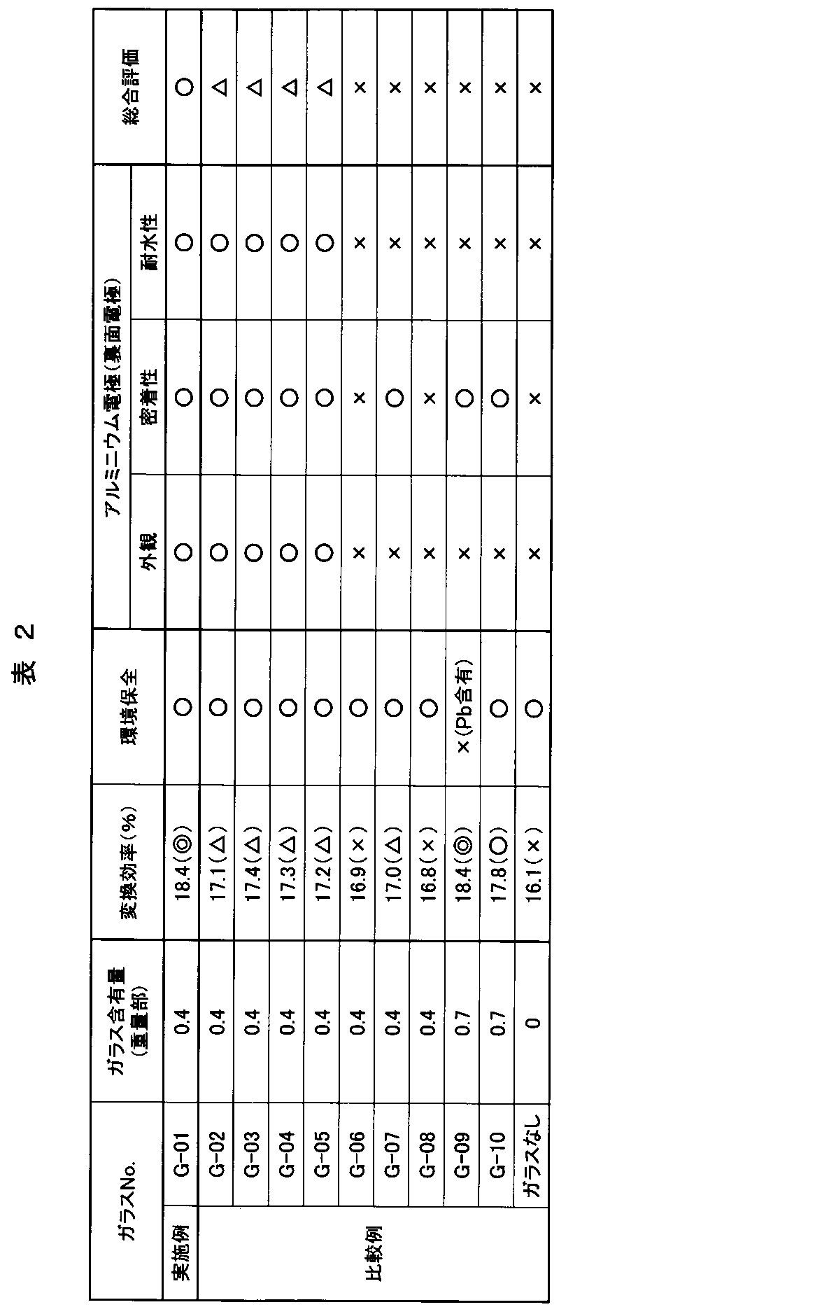
表2において、実施例V-P-B-O系ガラスG-01と比較例Pb-B-Si-O系ガラスG-09を用いたアルミニウム電極を裏面電極として搭載した太陽電池セルは、非常に高い変換効率を有していた。また、比較例Bi-B-Si-O系ガラスG-10を用いた場合にも比較的高い変換効率を示した。それ以外のガラスを用いた場合には変換効率は低めであった。また、ガラスを含有しない場合には、どんなガラスを使う場合よりも変換効率は低かった。環境保全に関しては、G-09は有害な鉛を多く含むため、太陽電池セルしても環境上問題はあるが、それ以外のガラスを用いた場合には問題はない。環境に配慮した上で、最も変換効率が高い太陽電池セル、すなわち最も高性能な電子部品は、実施例G-01のV-P-B-O系ガラスを電極に適用した場合であった。
また、表2に示すように、太陽電池セルに形成したアルミニウム電極の外観は、V2O5を主成分とする低融点ガラスG-01~05を用いた場合にはどれも良好であった。それ以外のガラスを用いた場合及びガラスを含有しなかった場合には、アルミニウム電極表面部に異物や凹凸が多数認められた。アルミニウム電極の密着性は、軟化点が比較的低く、500℃で軟化流動するガラスG-01~05、-07、-09及び-10を用いた場合には良好であった。
一方、軟化点が500℃以上と高いガラスG-06と-08を用いた場合、及びガラスを含有しなかった場合には、密着性は不十分であった。アルミニウム電極の耐水性は、先に説明した外観と同じ結果となり、V2O5を主成分とする低融点ガラスG-01~05を用いた場合にはどれも良好であった。
以上より、アルミニウム電極の外観、密着性、耐水性のどれも良好であったガラスはG-01~05であり、V2O5を主成分とする低融点ガラスであれば、アルミニウム電極に係わる生産性や信頼性を改善或いは向上できることが分かった。これは、アルミニウム粒子とV2O5を主成分とする低融点ガラス粒子が電極を焼成及び形成する際に良好なぬれ性と反応性を有するためと考えられる。しかし、V2O5を主成分とする低融点ガラスのほとんどは、セル変換効率が低下した。唯一、セル変換効率をPb-B-Si-O系ガラスG-09並みまで向上できたガラスは、実施例G-01のバナジウム、リン及びホウ素を含む酸化物ガラスのみであった。
また、このガラスには、実質的に鉛等の有害規制物質が含まれず、環境にも十分に配慮されたものであり、このガラスが適用された電極用導電性ペースト、及びこの導電性ペーストにより形成された電極を有する電子部品においても環境負荷への影響を低減することができる。RoHS規制やジョイントインダストリーガイドラインでは、電子部品の鉛含有量は1000ppm以下と規定されている。
このため、電子部品を構成する各材料においては、故意に有害な鉛を含有すべきではない。しかし、不純物として鉛が混入されてしまう場合があり、電子部品を構成する各材料においても電子部品同様に1000ppm以下とすることが好ましい。本発明による電極用V-P-B-O系ガラスは、環境負荷の影響を低減するために、これを前提に開発し、従来からのPb-B-Si-O系ガラスやBi-B-Si-O系ガラスを用いた場合より電子部品の性能や信頼性を向上できることを見出した。
実施例1において、アルミニウム電極に含有するガラスによって太陽電池セルの変換効率が異なることが分かった。この原因を究明するために、セル変換効率に影響すると言われているBSF層7や合金層8の状態をSEM-EDXによって、詳細に観察及び分析した。図5に表1及び表2で示したV-P-B-O系ガラスG-01を含むアルミニウム電極用導電性ペーストを用いて作製した太陽電池セルの裏面近傍の断面SEM写真を示す。
通常ではBSF層7は観測されないため、フッ硝酸水溶液を用いてエッチングすることによって観察した。
通常ではBSF層7は観測されないため、フッ硝酸水溶液を用いてエッチングすることによって観察した。
実施例1で述べたとおり、BSF層7は、裏面電極5よりアルミニウム成分がシリコン基板からなる半導体基板1へ拡散することによって形成される。その際に裏面電極5とBSF層7の間にアルミニウムとシリコンとの反応による合金層8も生成される。G-01以外のガラスG-02~10を用いた場合にも図5と同様に観察された。
詳細にSEM観察した結果、BSF層7や合金層8の厚みには、アルミニウム電極用ガラスによる大きな違いは観測されなかった。すなわち、太陽電池セルの変換効率とBSF層7や合金層8の厚みとの明確な相関が認められなかった。そこで、BSF層7や合金層8の組成を高感度のEDXによって分析した。合金層8においては、どのガラスを用いた場合でも、アルミニウムとシリコンの両方が検出された。その分析組成は、アルミニウムが90アトミック%以上と非常に多く、一方シリコンは10アトミック%以下と少なかった。この組成範囲内でのバラツキが同一太陽電池セル内でも大きく、太陽電池セルの変換効率と合金層8の組成との明確な関係を見出すことはできなかった。
次にBSF層7の組成を同様に高感度のEDXによって分析した。BSF層7の組成にガラスによる違いが認められた。図6にBSF層7中のアルミニウム(Al)濃度とアルミニウム電極用ガラス組成物の軟化点との関係を示す。ガラスの軟化点が低いほどBSF層7中のアルミニウム濃度が高くなることが分かった。しかし、表1と表2で示したとおり、そのアルミニウム濃度が高いほど、すなわち軟化点が低いガラスほど、太陽電池セルの変換効率が高くなっている訳ではなかった。そこで、BSF層7中の酸素濃度についても調べた。
図7にBSF層7中の酸素(O)濃度とアルミニウム電極用ガラス組成物の軟化点との関係を示す。BSF層7中のアルミニウム濃度と同様にガラスの軟化点が低いほど、BSF層7中の酸素濃度が高くなる傾向を示したが、実施例のV-P-B-O系ガラスG-01、比較例のPb-B-Si-O系ガラスG-09とBi-B-Si-O系ガラスG-10に関しては、この傾向に合わず、軟化点が低めでもBSF層7中の酸素濃度が低かった。すなわち、これらのガラスはシリコン基板を酸化させにくいとも言える。
表2で示したとおり、G-01、-09及び-10のガラスをアルミニウム電極に用いた場合には、太陽電池セルの変換効率が高かった。
以上より、BSF層7のアルミニウム濃度を高く、酸素濃度を低くできるアルミニウム電極用ガラス組成物が太陽電池セルの変換効率を向上できることが分かった。裏面電極5から半導体基板1へのアルミニウムの拡散量を増やすには、すなわちアルミニウム電極からシリコン基板へのアルミニウムの拡散量を増やすには、電極に含有するガラス組成物の軟化点を下げればよいが、一方酸素の拡散量を同時に減らすには、軟化、流動したガラス組成物がシリコン基板に接した際にそのガラス組成物からシリコン基板へ酸素が奪われないようにする必要があると考えられる。
比較例のPb-B-Si-O系ガラスG-09とBi-B-Si-O系ガラスG-10は大変還元されやすいガラスであるため、アルミニウム電極中で容易に還元され、酸素が奪われてしまい、シリコン基板を酸化するまでには至らなかったものと考えられる。その証拠にG-09と-10をそれぞれ含有した裏面電極5をX線回折すると、金属鉛や金属ビスマスの析出が認められた。これはG-09や-10のガラスがアルミニウム電極中で還元され、これらのガラスから析出したものである。
V2O5を主成分とする低融点ガラスG-02~05では、G-09や-10に比較すると還元しにくく、このような効果が得られないため、シリコン基板を酸化させやすいと考えられる。しかし、実施例のV-P-B-O系ガラスG-01も比較例のG-02~05と同様にV2O5を主成分とする低融点ガラスであるにもかかわらず、特異的にシリコン基板の酸化を抑制していた。これはG-01と、G-02~05では、ガラスの構造が異なるためである。図8にガラス構造中のP2O5とB2O3の状態を模式的に示す。
P2O5は、ガラス構造中で図8(1)に示すように一つのリン(P)に対して一つの二重結合酸素(O)を持ち、3つの架橋酸素(O)によりガラスの網目構造を形成している。B2O3は、ガラス構造中で図8(2)に示すように一つのホウ素(B)に対して3つの架橋酸素(O)よりガラスの網目構造を形成している。
これらに対して、P2O5とB2O3の両方を含有すると、ガラス構造中で図8(3)に示すようにリン(P)とホウ素(B)がそれぞれ4つの架橋酸素(O)と結合できるようになり、ガラスの網目構造が緻密化される。その際に、リン(P)はプラス(+)、ホウ素(B)はマイナス(-)にチャージされ、お互いが電気的に中和される。これはホウ酸異常現象と言われるガラスの特異現象であり、理論的にこの現象を最も効率的に発現させるためには、P2O5とB2O3の含有割合は、モル比で1:1、重量比で2:1である。
この現象を実施例のV-P-B-O系低融点ガラスG-01のガラス構造では採用した。これにより、シリコン基板への酸素の拡散、すなわちシリコン基板の酸化を抑制した。
これは、シリコン基板へ形成する電極であれば、アルミニウム電極以外にも有効に活用できる技術であることは言うまでもない。また、V2O5を主成分とすることによって軟化点を低温化し、シリコン基板へのアルミニウム拡散量を増加できるようにした。このようにシリコン基板への酸素拡散量の減少とアルミニウム拡散量の増加によって太陽電池セルの変換効率を向上した。太陽電池セルを例に説明したが、シリコン基板を用いた電子部品全般に渡り活用できる技術である。
これは、シリコン基板へ形成する電極であれば、アルミニウム電極以外にも有効に活用できる技術であることは言うまでもない。また、V2O5を主成分とすることによって軟化点を低温化し、シリコン基板へのアルミニウム拡散量を増加できるようにした。このようにシリコン基板への酸素拡散量の減少とアルミニウム拡散量の増加によって太陽電池セルの変換効率を向上した。太陽電池セルを例に説明したが、シリコン基板を用いた電子部品全般に渡り活用できる技術である。
さらに、V2O5を主成分とする低融点ガラスであるため、アルミニウム電極の外観等の不良率を低減でき、しかも密着性や耐湿性等の信頼性も向上できる。これはアルミニウムとのぬれ性や反応によるものであり、アルミニウムを主成分とするアルミニウム合金においても同様な効果が得られることは言うまでもない。また、太陽電池セルの裏面電極へ適用した例について説明したが、それ以外の電子部品のアルミニウム電極やアルミニウム合金電極にも適用できることは言うまでもない。
本実施例では、シリコン基板を用いた電子部品やアルミニウム電極に有効なV-P-B-O系低融点ガラスの組成を詳細に検討した。作製したV-P-B-O系低融点ガラスの配合組成とその特性を表3に示す。表3に示すGA-01~30のガラス作製方法について説明する。
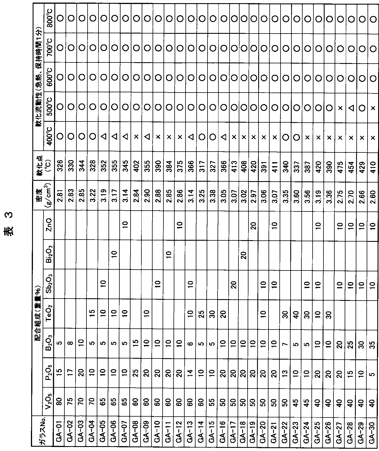
表3の配合組成で示した酸化物をガラス原料とし、それぞれの割合で各200gを配合、混合した。それを白金ルツボに入れ、電気炉中10℃/分の昇温速度で900~1100℃まで加熱し、攪拌しながら2時間保持した後にステンレス板へ流し込み、GA-01~30のガラスをそれぞれ作製した。作製したガラスをスタンプミルとジェットミルによって、平均粒径が1~2μmになるまで粉砕し、それぞれのガラス粒子を得た。
作製したガラスの密度はアルキメデス法により測定し、軟化点と軟化流動性は、実施例1と同様にして評価した。作製したV-P-B-O系低融点ガラスGA-01~30の密度は、2.60~3.60g/cm3の範囲にあり、従来からのPb-B-Si-O系低融点ガラスG-09やBi-B-Si-O系低融点ガラスG-10の密度に比べると約半分であった。
特に密度が小さかったガラスはGA-27~30であり、P2O5の含有量がB2O3の同等以下であった。それ以外のガラスは、P2O5の含有量をB2O3の含有量より約2倍多くし、実施例2で説明したホウ酸異常現象を積極的に活用しようとした。一方、上記密度範囲において、特に密度が大きいガラスは、TeO2を30重量%以上含有するGA-15、-22~24及び-26であった。
軟化点は、V2O5やTeO2の含有量が多く、P2O5が少ないガラスほど低い傾向を示した。軟化流動性は、600℃以上でどのガラスも良好な流動性を有していた。500℃においては、GA-27、-28及び-30以外は良好な流動性を有していた。また、400℃では、GA-05~07、-09、-13及び-16は軟化までし、GA-01~04、-14、-15、-22及び-23のみ良好な流動性を示した。軟化点同様にV2O5やTeO2の含有量が多く、P2O5が少ないガラスほど、低温での軟化流動性が良好である傾向を示した。
GA-01~30のガラス粒子を用いて、実施例1と同様にしてアルミニウム電極用導電性ペーストを作製した。ただし、バインダー樹脂にはニトロセルロース、溶剤にはブチルカルビトールアセテートを用いた。また、比較のため、実施例1と同様にしてPb-B-Si-O系低融点ガラスG-09とBi-B-Si-O系低融点ガラスG-10をそれぞれ含むアルミニウム電極用導電性ペースト、及びガラスなしのアルミニウム電極用導電性ペーストも作製した。
作製したアルミニウム電極用導電性ペーストを用いて、実施例1と同様にして図2~4で示した太陽電池セルを作製し、評価した。ただし、半導体基板1には、150mm角で厚み200μmのp型多結晶シリコン基板を用いた。作製した太陽電池セルの評価結果を表4に示す。
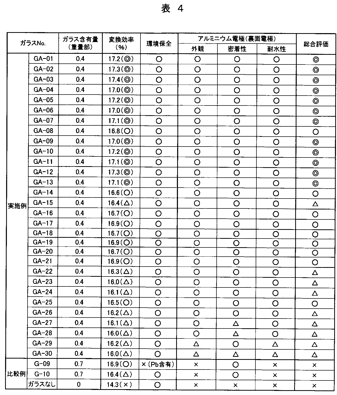
表4中の「変換効率」を評価するに当たっては、本実施例では半導体基板1に単結晶シリコン基板よりセル変換効率が低くでる多結晶シリコン基板を使用したため、多結晶シリコン基板としては非常に高い変換効率である17.0%以上で「◎」、16.5~17.0%で「○」、16.0~16.5%で「△」、16.0%未満で「×」とした。それ以外の評価では、実施例1と同じ方法で行った。ただし、「総合評価」において、「○」評価の中で特に変換効率に優れた太陽電池セルにおいて「◎」と評価した。
表4の太陽電池セルの評価結果よりアルミニウム電極用ガラス組成物としては、V-P-B-O系をベースにTe、Sb、Bi、Znのうち1種以上を含んでもよいことが分かった。これらTe、Sb、Bi、Znのうち1種以上を含有させることによって、ガラスの耐候性が向上し、アルミニウム電極用導電性ペーストを作製するまでのガラス粒子の取り扱い性が向上した。
太陽電池セルの総合評価が「○」以上のガラス組成範囲は、次の酸化物換算でV2O5が40~80重量%、P2O5が10~25重量%、B2O3が5~15重量%、TeO2が0~25重量%、Sb2O3が0~20重量%、Bi2O3が0~20重量%、及びZnOが0~20重量%であり、P2O5量がB2O3量より多く、しかもP2O5、B2O3及びTeO2の合計量が20~50重量%であった。ガラスの特性から考察すると、密度が2.81~3.25g/cm3、軟化点が420℃以下、及び500℃での流動性が良好であるV-P-B-O系低融点ガラスが有効であることが挙げられる。特に良好であった「◎」の総合評価されたガラス組成範囲は、次の酸化物換算でV2O5が60~80重量%、P2O5が10~20重量%、B2O3が5~10重量%、TeO2が0~15重量%、Sb2O3が0~10重量%、Bi2O3が0~10重量%、及びZnOが0~10重量%であり、P2O5、B2O3及びTeO2の合計量が20~40重量%であった。
上記組成範囲のアルミニウム電極用ガラス組成物は、シリコン基板へのアルミニウム成分の拡散を促進し、一方酸素の拡散を抑制できることから、太陽電池セルに限らず、シリコン基板を用いた電子部品全般に有効に適用できることは言うまでもない。また、特にアルミニウム電極には有効であるが、アルミニウム電極以外にも活用可能である。
本実施例では、アルミニウム電極中のV-P-B-O系低融点ガラスの含有量が太陽電池セルの変換効率に及ぼす影響について、詳細に検討した。このガラスには、表3と表4で示した実施例3でのGA-05を用いた。GA-05のガラス含有量はアルミニウム粒子100重量部に対して0~5重量部の範囲で検討した(0、0.2、0.4、0.7、1.0、1.5、2.0、2.5、3.0、3.5、4.0及び5.0重量部)。
実施例3と同様にして、ガラス含有量を変えアルミニウム電極用導電性ペーストを12種類作製した。作製したアルミニウム電極用導電性ペーストを裏面電極に用いて、実施例3と同様にして図2、図3、図4A、図4Bで示した太陽電池セルを作製し、セル変換効率を測定した。図9に太陽電池セルの変換効率とアルミニウム電極に含まれるV-P-B-O系ガラス組成物の含有量との関係を示す。裏面電極であるアルミニウム電極にガラスが含まれないと、太陽電池セルの変換効率は著しく低かったが、僅か0.2重量部のGA-05ガラスが含有されると、一気に変換効率が向上した。
GA-05ガラスが0.2~0.7重量部の範囲で17%以上と非常に高い変換効率が得られた。それ以上の含有量では、2重量部まで僅かに変換効率が減少したが、16.5%以上と良好な変換効率であった。2重量部を超えると、変換効率が著しく低下し、2.5重量部以上で16.0%を下回ってしまった。このようにアルミニウム電極中のガラス含有量とともに、変換効率が低下する原因として、シリコン基板への酸素の拡散量が増加、すなわちシリコン基板の酸化が進行するためと考えられる。
以上より、太陽電池セルの裏面電極として適用するアルミニウム電極中のV-P-B-O系低融点ガラスの含有量は、0.2~2重量部の範囲が好ましかった。特に0.2~0.7重量部の範囲が有効であった。これは太陽電池セルに限らず、シリコン基板を用いた電子部品全般に有効に適用できることは言うまでもない。また、特にアルミニウム電極には有効であるが、アルミニウム電極以外にも活用できることは言うまでもない。
本実施例では、アルミニウム合金電極中のV-P-B-O系低融点ガラスの含有量がその電極の比抵抗に及ぼす影響について検討した。アルミニウム合金としては、Al-10重量%銀の粒子を用いた。アトマイズ法により作製し、分級することによって、3μm以下のアルミニウム合金粒子とした。このガラスには、表3と表4で示した実施例3でのGA-09を用いた。
GA-09のガラス含有量はアルミニウム合金粒子100重量部に対して0~25重量部の範囲で検討した(0、0.2、2.0、5.0、10.0、15.0、20.0、及び25.0重量部)。
実施例3と同様にして、ガラス含有量を変えアルミニウム合金電極用導電性ペーストを8種類作製した。ただし、バインダー樹脂にはニトロセルロースに代えてエチルセルロースを用いた。溶剤はブチルカルビトールアセテートである。作製したアルミニウム合金電極用導電性ペーストを単結晶シリコン基板へスクリーン印刷法で塗布し、150℃で10分間乾燥した。その後、電気炉に投入し、大気中10℃/分の昇温速度で500℃まで加熱し、10分間保持した後に炉冷した。アルミニウム合金電極の膜厚は約20μmであった。シリコン基板に形成したアルミニウム合金電極の比抵抗を四探針法によって測定した。
図10にアルミニウム合金電極の比抵抗とその電極に含まれるガラス組成物の含有量との関係を示す。図10に示されるように、アルミニウム合金電極にガラスが含まれないと、その比抵抗は著しく高かったが、僅か0.2重量部のGA-09ガラスが含有されると、一気に比抵抗が低下した。GA-05ガラスが0.2~15重量部の範囲で10-5Ωcmオーダーの比抵抗を達成した。20重量部以上の含有量では、アルミニウム合金電極の比抵抗が再び大きいものとなった。
このことから、アルミニウム合金電極を単に配線として用いる場合やシリコン基板を用いない電子部品へ適用する場合には、電極中のV-P-B-O系低融点ガラスの含有量は、0.2~15重量部の範囲が好ましいことが分かった。本実施例では、アルミニウム合金電極においてV-P-B-O系低融点ガラスを検討したが、アルミニウム電極やそれ以外の電極にも活用できることは言うまでもない。
本実施例では、プラズマディスプレイパネル(PDP)の電極へ適用した例について説明する。図11は、プラズマディスプレイパネルの1例を示す断面模式図である。以下、図11を参照しながら説明する。
はじめに、一般的なプラズマディスプレイパネルについて説明する。プラズマディスプレイパネル11は、前面板12と背面板13とが100~150μmの間隙をもって対向させて配置され、各基板(前面板12と背面板13)の間隙は隔壁14で維持されている。前面板12と背面板13との周縁部は封着材料15で気密に封止され、パネル内部に希ガスが充填されている。
前面板12上には表示電極20が形成され、表示電極20上に誘電体層23が形成され、誘電体層23上に放電から表示電極20等を保護するための保護層25(例えば、MgOの蒸着膜)が形成されている。また、背面板13上にはアドレス電極21が形成され、アドレス電極21上に誘電体層24が形成され、誘電体層24上にセル16を構成するための隔壁14が設けられている。この隔壁14は、少なくともガラス組成物とフィラーとを含む材料を500~600℃で焼結した構造体よりなり、通常、ストライプ状あるいはボックス状の構造体である。また、背面板13のアドレス電極21は、前面板12の表示電極20に対して直交するように形成されている。
隔壁14により区切られた微小空間(セル16)には蛍光体が充填されている。セル16中の蛍光体は、蛍光体用のペーストをセル16に充填し450~500℃で焼成することによって形成される。赤色蛍光体17が充填されたセルと緑色蛍光体18が充填されたセルと青色蛍光体19が充填されたセルとの3色のセルで1画素が構成される。各画素は、表示電極20とアドレス電極21に掛かる信号に応じて種々の色を発光する。
封着材料15は、ディスペンサー法や印刷法等により前面板12または背面板13のどちらか一方の周縁部に事前に塗布される。塗布された封着材料15は、蛍光体17~19の焼成と同時に仮焼成されることもある。塗布された封着材料を仮焼成することによって、ガラス封着部の気泡を著しく低減することができ、信頼性の高い(すなわち気密性の高い)ガラス封着部が得られるためである。
前面板12と背面板13との封着は、別々に作製した前面板12と背面板13とを正確に位置合わせしながら対抗させて配置し、420~500℃に加熱して行われる。このとき、加熱しながらセル16内部のガスを排気して替わりに希ガスを封入し、電子部品としてのプラズマディスプレイパネルが完成する。なお、封着材料の仮焼成時やガラス封着時に、封着材料15が表示電極20やアドレス電極21と直接的に接触することがあるが、電極配線材料と封着材料とが化学反応しないように構成されていることが肝要である。
プラズマディスプレイパネルのセル16を点灯(発光)するには、点灯させたいセル16の表示電極20とアドレス電極21との間に電圧を印加してセル16内にアドレス放電を行い、希ガスをプラズマ状態に励起してセル内に壁電荷を蓄積する。次に、表示電極対に一定の電圧を印加することで、壁電荷が蓄積されたセルのみに表示放電が起こり紫外線22を発生させる。そして、この紫外線22を利用して蛍光体17~19を発光させてことで、画像情報が表示される。
ここにおいて、表示電極20やアドレス電極21としては、良好な電気的性質と製造中の耐酸化性を考慮して銀厚膜の電極配線が従来から使用されている。表示電極20及びアドレス電極21の形成は、スパッタリング法によっても可能であるが、製造コスト低減のためには印刷法が有利である。なお、誘電体層23,24は、通常、印刷法で形成される。また、印刷法で形成される表示電極20、アドレス電極21、誘電体層23,24は、酸化雰囲気中550~620℃の温度範囲で焼成されることが一般的である。
前述したように、銀厚膜の電極配線は銀がマイグレーション現象を起こし易いという問題があるとともに材料コストが高いという問題がある。それらの問題を解決するためには、銀厚膜の電極配線からアルミニウム厚膜或いはアルミニウム合金厚膜の電極配線への変更が好ましい。しかしながら、アルミニウム厚膜或いはアルミニウム合金厚膜の電極配線へ変更するためには、電極配線の比抵抗が低いことと、電極配線と誘電体層とが化学反応しないこと、さらに形成した電極配線の近傍に空隙(気泡等)が発生して電気的耐圧性が低下しないこと等の条件を満たす必要がある。
アルミニウム電極用導電性ペーストに含有させる金属粒子として、実施例5で用いたアルミニウム合金粒子(Al-10重量%Ag)を用意した。また、実施例5で用いたV-P-B-O系低融点ガラスGA-09のガラス粒子が上記アルミニウム合金粒子を100重量部とした場合に10重量部となるように混合した粉末に、さらにバインダー樹脂と溶剤とを添加・混錬してアルミニウム電極用導電性ペーストを作製した。この際、バインダー樹脂にはエチルセルロースを用い、溶剤にはα-テルピネオールを用いた。
本発明に係るプラズマディスプレイパネルを作製した。まず、前記のアルミニウム電極用導電性ペーストを用い、スクリーン印刷法によって前面板12と背面板13の全面に塗布し、大気中150℃で乾燥した。フォトリソグラフィによって塗布膜の余分な箇所を除去して電極配線をパターニングし、その後、大気中580℃で10分間焼成して表示電極20とアドレス電極21を形成した。
次に、誘電体層23,24をそれぞれ塗布し、大気中560℃で30分間焼成した。このようにして作製した前面板12と背面板13を対抗させて配置し、外縁部をガラス封着して図11に示したような構造を有するプラズマディスプレイパネルを作製した。
本発明に係るアルミニウム電極用導電性ペーストを用いて形成した電極配線(表示電極20とアドレス電極21)は、表示電極20と誘電体層23との界面部や、アドレス電極21と誘電体層24の界面部に空隙の発生も認められず、外観上良好な状態でプラズマディスプレイパネルを作製することができた。
続いて、作製したプラズマディスプレイパネルの点灯実験を行った。表示電極20及びアドレス電極21の比抵抗が増加することは無かった。また、電気的耐圧性が低下することもなくパネルを点灯することができた。さらに、銀厚膜の電極配線のようなマイグレーション現象も生じず、その他特に支障があるような点は認められなかった。以上のことから、本発明のアルミニウム電極用導電性ペーストは、プラズマディスプレイパネルの電極配線として適用できることが確認された。また、高価な銀厚膜の電極配線の代替となり得るので、コスト低減にも大きく貢献できる。
本実施例では、本発明に係る電子部品として多層配線基板の電極へ適用した例について説明する。図12は、LTCC(Low Temperature Co-fired Ceramics)の多層配線基板(5層)の焼成前の構造例を示す断面模式図である。
図12に示すように、多層配線基板30は配線(配線用導電性ペースト31)が三次元的に形成されている配線基板である。以下、図12を参照しながら説明する。
図12に示すように、多層配線基板30は配線(配線用導電性ペースト31)が三次元的に形成されている配線基板である。以下、図12を参照しながら説明する。
多層配線基板の製造は、通常、次のような手順で行われる。まず、ガラス粉末とセラミックス粉末とバインダーとを含むグリーンシート32を用意し、所望の位置に貫通孔33を開ける。貫通孔33の開いたグリーンシート32に対し、配線用導電性ペースト31を所望の配線パターンに印刷法で塗布するとともに、貫通孔33にも充填する。必要に応じて、グリーンシート32の裏面にも配線用導電性ペースト31を印刷法にて塗布する。グリーンシート32の裏面に塗布する場合には、表面に塗布した配線用導電性ペースト31を乾燥させてから行う。
所定の配線パターンを形成した複数のグリーンシート32を積層し、一体で焼成することによりLTCCの多層配線基板が製造される。なお、焼成条件としては、大気中で900℃前後の温度が一般的である。また、配線用導電性ペーストとしては、良好な電気的性質と製造中の耐酸化性を考慮して銀の導電性ペーストが通常使用されている。
マイグレーション現象の対策に有利でしかも安価な銅の導電性ペーストを使用した検討も行われている。しかしながら、銅粒子の酸化防止を目的として窒素雰囲気中で焼成されるため、導電性ペースト31やグリーンシート32中のバインダーの焼成除去(脱バインダー)が上手くいかず、緻密な多層配線基板を得ることが難しかった。
また、銅を用いた従来の導電性ペーストにおいては、焼成中にグリーンシート32と導電性ペースト31とが接する部分でガラス相が軟化・流動しやすく銅粒子が酸化され、電極配線の比抵抗が増大する問題があった。さらに、ガラス相との化学反応により該界面部に空隙が発生することがあった。
本発明に係る多層配線基板を作製した。配線用導電性ペースト31としては、実施例6で検討したアルミニウム電極用導電性ペーストを用い、上述と同様の手順で図12に示すような多層配線の積層体を形成して、大気中900℃で30分間焼成した。
作製した多層配線基板において電極配線の比抵抗を測定したところ、設計通りの値が得られた。次に、作製した多層配線基板の断面観察を行った。その結果、作製した多層配線基板は十分緻密に焼成されていた。そのため、比抵抗も良好な設計通りの値となったと思われる。これは、昇降過程において略完全に脱バインダーが完了していたためと考えられた。また、ガラス相と電極配線との化学反応による界面近傍での空隙も発生していないことが確認された。以上のことから、本発明のアルミニウム電極用導電性ペーストは、多層配線基板の電極配線として適用できることが確認された。また、高価な銀厚膜の電極配線の代替となり得るので、コスト低減にも大きく貢献できる
10…太陽電池セル、1…p型半導体基板、2…n型半導体層、3…反射防止層、4…受光面電極、5…裏面電極、6…出力電極、7…BSF層、8…合金層、11…プラズマディスプレイパネル、12…前面板、13…背面板、14…隔壁、15…封着材料、16…セル、17…赤色蛍光体、18…緑色蛍光体、19…青色蛍光体、20…表示電極、21…アドレス電極、22…紫外線、23、24…誘電体層、25…保護層、30…多層配線基板、31…配線用導電性ペースト、32…グリーンシート、33…貫通孔。
Claims (23)
- 金属粒子と、ガラス相とを有する電極がシリコン基板に形成された電子部品であって、該ガラス相がバナジウム、リン及びホウ素を含む酸化物ガラスであることを特徴とする電子部品。
- 請求項1において、前記ガラス相が次の酸化物換算でV2O5が60~80重量%、P2O5が10~25重量%、B2O3が5~15重量%を含み、P2O5量がB2O3量より多いことを特徴とする電子部品。
- 請求項1又は2において、前記ガラス相が次の酸化物換算でV2O5が70~80重量%、P2O5が10~20重量%、B2O3が5~10重量%であることを特徴とする電子部品。
- 請求項1において、前記ガラス相がさらにテルル、アンチモン、ビスマス及び亜鉛のうち1種以上を含むことを特徴とする電子部品。
- 請求項4において、前記ガラス相が次の酸化物換算でV2O5が40~80重量%、P2O5が10~25重量%、B2O3が5~15重量%、TeO2が0~25重量%、Sb2O3が0~20重量%、Bi2O3が0~20重量%、及びZnOが0~20重量%であり、P2O5量がB2O3量より多く、しかもP2O5、B2O3及びTeO2の合計量がガラス相の20~50重量%であることを特徴とする電子部品。
- 請求項4又は5において、前記ガラス相が次の酸化物換算でV2O5が60~80重量%、P2O5が10~20重量%、B2O3が5~10重量%、TeO2が0~15重量%、Sb2O3が0~10重量%、Bi2O3が0~10重量%、及びZnOが0~10重量%であり、P2O5、B2O3及びTeO2の合計量がガラス相の20~40重量%であることを特徴とする電子部品。
- 請求項1ないし6のいずれかにおいて、前記金属粒子の100重量部に対して前記ガラス相が0.2~2重量部の割合で含有されていることを特徴とする電子部品。
- 請求項1ないし7のいずれかにおいて、前記金属粒子がアルミニウム或いはアルミニウム合金であり、かつ前記シリコン基板がp型半導体を有し、該p型半導体に前記電極が形成されていることを特徴とする電子部品。
- 請求項1から8のいずれかにおいて、前記シリコン基板がpn接合を有する太陽電池セルであることを特徴とする電子部品。
- 請求項1ないし9のいずれかにおいて、前記アルミニウム電極用ガラス組成物の鉛の含有量が1000ppm以下であることを特徴とする電子部品。
- アルミニウム或いはアルミニウム合金からなる金属粒子と、ガラス粒子が、バインダー樹脂が溶解した溶剤中に分散したアルミニウム電極用導電性ペーストであって、該ガラス粒子がバナジウム、リン及びホウ素を含む酸化物ガラスであることを特徴とするアルミニウム電極用導電性ペースト。
- 請求項11において、前記ガラス粒子が次の酸化物換算でV2O5が60~80重量%、P2O5が10~25重量%、B2O3が5~15重量%を含み、P2O5量がB2O3量より多いことを特徴とするアルミニウム電極用導電性ペースト。
- 請求項11において、前記ガラス粒子が次の酸化物換算でV2O5が70~80重量%、P2O5が10~20重量%、B2O3が5~10重量%を含み、P2O5量がB2O3量より多いことを特徴とするアルミニウム電極用導電性ペースト。
- 請求項11において、前記ガラス粒子がさらにテルル、アンチモン、ビスマス及び亜鉛のうち1種以上を含むことを特徴とするアルミニウム電極用導電性ペースト。
- 請求項14において、前記ガラス粒子が次の酸化物換算でV2O5が40~80重量%、P2O5が10~25重量%、B2O3が5~15重量%、TeO2が0~25重量%、Sb2O3が0~20重量%、Bi2O3が0~20重量%、及びZnOが0~20重量%であり、P2O5量がB2O3量より多く、しかもP2O5、B2O3及びTeO2の合計量がガラス相の20~50重量%であることを特徴とするアルミニウム電極用導電性ペースト。
- 請求項14において、前記ガラス粒子が次の酸化物換算でV2O5が60~80重量%、P2O5が10~20重量%、B2O3が5~10重量%、TeO2が0~15重量%、Sb2O3が0~10重量%、Bi2O3が0~10重量%、及びZnOが0~10重量%であり、P2O5、B2O3及びTeO2の合計量が20~40重量%であることを特徴とするアルミニウム電極用導電性ペースト。
- 請求項11ないし16のいずれかにおいて、前記ガラス粒子が前記金属粒子の100重量部に対して0.2~15重量部の割合で含有されていることを特徴とするアルミニウム電極用導電性ペースト。
- 請求項11ないし17のいずれかにおいて、前記ガラス粒子が前記金属粒子の100重量部に対して0.2~2重量部の割合で含有されていることを特徴とするアルミニウム電極用導電性ペースト。
- 請求項11ないし18のいずれかにおいて、前記アルミニウム電極用ガラス組成物の鉛の含有量が1000ppm以下であることを特徴とするアルミニウム電極用導電性ペースト。
- アルミニウム又はアルミニウム合金粉末を含有するアルミニウム電極に含まれるガラス組成物であって、該ガラス組成物がバナジウム、リン及びホウ素を含み、さらにテルル、アンチモン、ビスマス及び亜鉛のうち1種以上を含む酸化物ガラスであり、軟化点が420℃以下で、500℃で流動することを特徴とするアルミニウム電極用ガラス組成物。
- 請求項20において、前記アルミニウム電極用ガラス組成物が、酸化物換算でV2O5が40~80重量%、P2O5が10~25重量%、B2O3が5~15重量%、TeO2が0~25重量%、Sb2O3が0~20重量%、Bi2O3が0~20重量%、及びZnOが0~20重量%であり、P2O5量がB2O3量より多く、かつP2O5、B2O3及びTeO2の合計量が20~50重量%であることを特徴とするアルミニウム電極用ガラス組成物。
- 請求項20において、前記アルミニウム電極用ガラス組成物が次の酸化物換算でV2O5が60~80重量%、P2O5が10~20重量%、B2O3が5~10重量%、TeO2が0~15重量%、Sb2O3が0~10重量%、Bi2O3が0~10重量%、及びZnOが0~10重量%であり、P2O5、B2O3及びTeO2の合計量が20~40重量%であることを特徴とするアルミニウム電極用ガラス組成物。
- 請求項20ないし22のいずれかにおいて、前記アルミニウム電極用ガラス組成物の鉛の含有量が1000ppm以下であることを特徴とするアルミニウム電極用ガラス組成物。
Applications Claiming Priority (2)
| Application Number | Priority Date | Filing Date | Title |
|---|---|---|---|
| JP2011087120A JP5673316B2 (ja) | 2011-04-11 | 2011-04-11 | 電子部品、それに適用されるアルミニウム電極用導電性ペースト、及びアルミニウム電極用ガラス組成物 |
| JP2011-087120 | 2011-04-11 |
Publications (1)
| Publication Number | Publication Date |
|---|---|
| WO2012141187A1 true WO2012141187A1 (ja) | 2012-10-18 |
Family
ID=47009358
Family Applications (1)
| Application Number | Title | Priority Date | Filing Date |
|---|---|---|---|
| PCT/JP2012/059850 Ceased WO2012141187A1 (ja) | 2011-04-11 | 2012-04-11 | 電子部品、それに適用されるアルミニウム電極用導電性ペースト、及びアルミニウム電極用ガラス組成物 |
Country Status (3)
| Country | Link |
|---|---|
| JP (1) | JP5673316B2 (ja) |
| TW (1) | TWI478890B (ja) |
| WO (1) | WO2012141187A1 (ja) |
Cited By (8)
| Publication number | Priority date | Publication date | Assignee | Title |
|---|---|---|---|---|
| EP2750141A1 (en) * | 2012-12-28 | 2014-07-02 | Heraeus Precious Metals GmbH & Co. KG | An electro-conductive paste comprising coarse inorganic oxide particles in the preparation of electrodes in MWT solar cells |
| EP2750140A1 (en) * | 2012-12-28 | 2014-07-02 | Heraeus Precious Metals GmbH & Co. KG | An electro-conductive paste comprising a vanadium containing compound and a phosphorus containing material in the preparation of electrodes in MWT solar cells |
| EP2750139A1 (en) * | 2012-12-28 | 2014-07-02 | Heraeus Precious Metals GmbH & Co. KG | An electro-conductive paste comprising a vanadium containing compound in the preparation of electrodes in MWT solar cells |
| EP2750142A1 (en) * | 2012-12-28 | 2014-07-02 | Heraeus Precious Metals GmbH & Co. KG | An electro-conductive paste comprising an inorganic reaction system with a high glass transition temperature in the preparation of electrodes in MWT solar cells |
| CN109564945A (zh) * | 2016-08-23 | 2019-04-02 | 纳美仕有限公司 | 导电性糊剂和太阳能电池 |
| TWI687941B (zh) * | 2019-01-14 | 2020-03-11 | 磐采股份有限公司 | 導電膠及應用該導電膠之太陽能電池 |
| US10720260B2 (en) | 2014-11-13 | 2020-07-21 | Samsung Sdi Co., Ltd. | Paste for forming solar cell electrode and electrode prepared using the same |
| GB2589703A (en) * | 2019-10-17 | 2021-06-09 | Johnson Matthey Plc | Composition, paste and methods |
Families Citing this family (8)
| Publication number | Priority date | Publication date | Assignee | Title |
|---|---|---|---|---|
| KR101587683B1 (ko) * | 2013-02-15 | 2016-01-21 | 제일모직주식회사 | 태양전지 전극 형성용 조성물 및 이로부터 제조된 전극 |
| JP6272332B2 (ja) * | 2013-08-30 | 2018-01-31 | 京セラ株式会社 | 太陽電池素子およびその製造方法 |
| CN104835606B (zh) * | 2015-04-03 | 2017-10-10 | 兴勤(常州)电子有限公司 | 电子元器件多层合金电极及其制备方法 |
| JP6766054B2 (ja) * | 2015-09-24 | 2020-10-07 | 東洋アルミニウム株式会社 | ペースト組成物及びシリコンゲルマニウム層の形成方法 |
| WO2017126378A1 (ja) * | 2016-01-18 | 2017-07-27 | 株式会社日立製作所 | 無鉛ガラス組成物、ガラス複合材料、ガラスペースト、封止構造体、電気電子部品及び塗装部品 |
| JP2017218335A (ja) * | 2016-06-03 | 2017-12-14 | 旭硝子株式会社 | ガラス、導電ペーストおよび太陽電池 |
| JPWO2022176519A1 (ja) * | 2021-02-16 | 2022-08-25 | ||
| JP7803746B2 (ja) * | 2022-03-07 | 2026-01-21 | 東洋アルミニウム株式会社 | TOPCon型太陽電池電極用導電性アルミニウムペースト組成物及びその焼成物である電極が積層されているTOPCon型太陽電池 |
Citations (5)
| Publication number | Priority date | Publication date | Assignee | Title |
|---|---|---|---|---|
| JP2009530845A (ja) * | 2006-03-20 | 2009-08-27 | フエロ コーポレーション | アルミニウム−ボロン太陽電池コンタクト |
| JP2010161331A (ja) * | 2008-12-12 | 2010-07-22 | Hitachi Ltd | 電極,電極ペースト及びそれを用いた電子部品 |
| JP2010533379A (ja) * | 2007-07-09 | 2010-10-21 | フエロ コーポレーション | アルミニウムと、ホウ素、チタン、ニッケル、錫、銀、ガリウム、亜鉛、インジウム、及び銅のうち少なくとも1種とを含有する太陽電池コンタクト |
| WO2010147160A1 (ja) * | 2009-06-17 | 2010-12-23 | 旭硝子株式会社 | 電極形成用ガラスフリット、およびこれを用いた電極形成用導電ペースト、太陽電池 |
| JP2011035024A (ja) * | 2009-07-30 | 2011-02-17 | Toyo Aluminium Kk | ペースト組成物およびそれを用いた太陽電池素子 |
Family Cites Families (1)
| Publication number | Priority date | Publication date | Assignee | Title |
|---|---|---|---|---|
| CN101265023B (zh) * | 2007-03-15 | 2010-05-26 | 北京印刷学院 | 钒银低熔玻璃和含有该玻璃的导电浆料 |
-
2011
- 2011-04-11 JP JP2011087120A patent/JP5673316B2/ja not_active Expired - Fee Related
-
2012
- 2012-04-11 TW TW101112860A patent/TWI478890B/zh active
- 2012-04-11 WO PCT/JP2012/059850 patent/WO2012141187A1/ja not_active Ceased
Patent Citations (5)
| Publication number | Priority date | Publication date | Assignee | Title |
|---|---|---|---|---|
| JP2009530845A (ja) * | 2006-03-20 | 2009-08-27 | フエロ コーポレーション | アルミニウム−ボロン太陽電池コンタクト |
| JP2010533379A (ja) * | 2007-07-09 | 2010-10-21 | フエロ コーポレーション | アルミニウムと、ホウ素、チタン、ニッケル、錫、銀、ガリウム、亜鉛、インジウム、及び銅のうち少なくとも1種とを含有する太陽電池コンタクト |
| JP2010161331A (ja) * | 2008-12-12 | 2010-07-22 | Hitachi Ltd | 電極,電極ペースト及びそれを用いた電子部品 |
| WO2010147160A1 (ja) * | 2009-06-17 | 2010-12-23 | 旭硝子株式会社 | 電極形成用ガラスフリット、およびこれを用いた電極形成用導電ペースト、太陽電池 |
| JP2011035024A (ja) * | 2009-07-30 | 2011-02-17 | Toyo Aluminium Kk | ペースト組成物およびそれを用いた太陽電池素子 |
Cited By (16)
| Publication number | Priority date | Publication date | Assignee | Title |
|---|---|---|---|---|
| CN105144304A (zh) * | 2012-12-28 | 2015-12-09 | 赫劳斯德国有限两和公司 | 制备mwt太阳能电池电极中的包含含钒化合物的导电浆料 |
| US10002977B2 (en) | 2012-12-28 | 2018-06-19 | Heraeus Deutschland GmbH & Co. KG | Electro-conductive paste comprising coarse inorganic oxide particles in the preparation of electrodes in MWT solar cells |
| EP2750139A1 (en) * | 2012-12-28 | 2014-07-02 | Heraeus Precious Metals GmbH & Co. KG | An electro-conductive paste comprising a vanadium containing compound in the preparation of electrodes in MWT solar cells |
| EP2750142A1 (en) * | 2012-12-28 | 2014-07-02 | Heraeus Precious Metals GmbH & Co. KG | An electro-conductive paste comprising an inorganic reaction system with a high glass transition temperature in the preparation of electrodes in MWT solar cells |
| WO2014102002A1 (en) * | 2012-12-28 | 2014-07-03 | Heraeus Precious Metals Gmbh & Co. Kg | An electro-conductive paste comprising a vanadium containing compound in the preparation of electrodes in mwt solar cells |
| WO2014102004A1 (en) * | 2012-12-28 | 2014-07-03 | Heraeus Precious Metals Gmbh & Co. Kg | An electro-conductive paste comprising a vanadium containing compound and a phosphorus containing material in the preparation of electrodes in mwt solar cells |
| EP2750140A1 (en) * | 2012-12-28 | 2014-07-02 | Heraeus Precious Metals GmbH & Co. KG | An electro-conductive paste comprising a vanadium containing compound and a phosphorus containing material in the preparation of electrodes in MWT solar cells |
| WO2014101999A1 (en) * | 2012-12-28 | 2014-07-03 | Heraeus Precious Metals Gmbh & Co. Kg | An electro-conductive paste comprising coarse inorganic oxide particles in the preparation of electrodes in mwt solar cells |
| EP2750141A1 (en) * | 2012-12-28 | 2014-07-02 | Heraeus Precious Metals GmbH & Co. KG | An electro-conductive paste comprising coarse inorganic oxide particles in the preparation of electrodes in MWT solar cells |
| WO2014102000A1 (en) * | 2012-12-28 | 2014-07-03 | Heraeus Precious Metals Gmbh & Co. Kg | An electro-conductive paste comprising an inorganic reaction system with a high glass transition temperature in the preparation of electrodes in mwt solar cells |
| US10720260B2 (en) | 2014-11-13 | 2020-07-21 | Samsung Sdi Co., Ltd. | Paste for forming solar cell electrode and electrode prepared using the same |
| CN109564945A (zh) * | 2016-08-23 | 2019-04-02 | 纳美仕有限公司 | 导电性糊剂和太阳能电池 |
| TWI687941B (zh) * | 2019-01-14 | 2020-03-11 | 磐采股份有限公司 | 導電膠及應用該導電膠之太陽能電池 |
| GB2589703A (en) * | 2019-10-17 | 2021-06-09 | Johnson Matthey Plc | Composition, paste and methods |
| GB2589703B (en) * | 2019-10-17 | 2022-01-12 | Johnson Matthey Advanced Glass Tech B V | Composition for sealing inorganic substrates |
| US12497325B2 (en) | 2019-10-17 | 2025-12-16 | Fenzi Agt Netherlands B.V. | Composition, paste and methods |
Also Published As
| Publication number | Publication date |
|---|---|
| JP5673316B2 (ja) | 2015-02-18 |
| TWI478890B (zh) | 2015-04-01 |
| TW201249771A (en) | 2012-12-16 |
| JP2012218982A (ja) | 2012-11-12 |
Similar Documents
| Publication | Publication Date | Title |
|---|---|---|
| JP5673316B2 (ja) | 電子部品、それに適用されるアルミニウム電極用導電性ペースト、及びアルミニウム電極用ガラス組成物 | |
| JP5699933B2 (ja) | ガラス組成物およびそれを用いた導電性ペースト組成物、電極配線部材と電子部品 | |
| JP5826178B2 (ja) | 電極用ガラス組成物、及びそれを用いた電極用ペースト、並びにそれを適用した電子部品 | |
| JP5497504B2 (ja) | 電子部品 | |
| KR101155536B1 (ko) | 저융점 유리조성물, 그것을 사용한 저융점 봉착재료 및 전자부품 | |
| CN102770382B (zh) | 铝电极配线用玻璃组合物和导电糊、具备该铝电极配线的电子部件及该电子部件的制造方法 | |
| CN102318013A (zh) | 导电性浆料及具备使用其的电极配线的电子部件 | |
| US8884277B2 (en) | Thick film conductive composition and use thereof | |
| JP5494619B2 (ja) | 電子部品、それに適用されるアルミニウム電極用導電性ペースト、及びアルミニウム電極用ガラス組成物 | |
| WO2023190282A1 (ja) | 導電性ペースト、太陽電池及び太陽電池の製造方法 | |
| JP5747096B2 (ja) | 導電性ペースト | |
| CN103959394A (zh) | 太阳能电池和该太阳能电池所使用的膏材料 | |
| WO2024100947A1 (ja) | 太陽電池 | |
| WO2024257439A1 (ja) | 導電性ペースト、導電性ペーストの使用、太陽電池及び太陽電池の製造方法 |
Legal Events
| Date | Code | Title | Description |
|---|---|---|---|
| 121 | Ep: the epo has been informed by wipo that ep was designated in this application |
Ref document number: 12771387 Country of ref document: EP Kind code of ref document: A1 |
|
| NENP | Non-entry into the national phase |
Ref country code: DE |
|
| 122 | Ep: pct application non-entry in european phase |
Ref document number: 12771387 Country of ref document: EP Kind code of ref document: A1 |