WO2012141043A1 - 支持構造及び計測装置 - Google Patents
支持構造及び計測装置 Download PDFInfo
- Publication number
- WO2012141043A1 WO2012141043A1 PCT/JP2012/059083 JP2012059083W WO2012141043A1 WO 2012141043 A1 WO2012141043 A1 WO 2012141043A1 JP 2012059083 W JP2012059083 W JP 2012059083W WO 2012141043 A1 WO2012141043 A1 WO 2012141043A1
- Authority
- WO
- WIPO (PCT)
- Prior art keywords
- region
- support
- supported
- area
- measurement
- Prior art date
- Legal status (The legal status is an assumption and is not a legal conclusion. Google has not performed a legal analysis and makes no representation as to the accuracy of the status listed.)
- Ceased
Links
Images











Classifications
-
- G—PHYSICS
- G01—MEASURING; TESTING
- G01N—INVESTIGATING OR ANALYSING MATERIALS BY DETERMINING THEIR CHEMICAL OR PHYSICAL PROPERTIES
- G01N21/00—Investigating or analysing materials by the use of optical means, i.e. using sub-millimetre waves, infrared, visible or ultraviolet light
- G01N21/62—Systems in which the material investigated is excited whereby it emits light or causes a change in wavelength of the incident light
- G01N21/63—Systems in which the material investigated is excited whereby it emits light or causes a change in wavelength of the incident light optically excited
- G01N21/64—Fluorescence; Phosphorescence
- G01N21/645—Specially adapted constructive features of fluorimeters
- G01N21/648—Specially adapted constructive features of fluorimeters using evanescent coupling or surface plasmon coupling for the excitation of fluorescence
Definitions
- the present invention relates to a measuring device that performs measurement by surface plasmon excitation fluorescence spectroscopy and a support structure in the measuring device.
- SPFS surface plasmon excitation fluorescence spectroscopy
- the evanescent wave leaking from the interface becomes stronger as the p-polarized component of the excitation light incident on the interface between the metal film and the dielectric medium increases.
- the s-polarized component of the excitation light incident on the interface between the metal film and the dielectric medium does not contribute to the emission of surface plasmon excitation fluorescence and causes autofluorescence of the dielectric medium.
- the polarization component of the excitation light applied to the dielectric medium is adjusted so that the p-polarized component is incident exclusively on the interface between the metal film and the dielectric medium.
- Patent document 1 is an example.
- a “transparent plate 17” that is a dielectric medium is sandwiched between “pressors 26 and 27”.
- An object of the present invention is to provide a support structure and a measurement apparatus that improve the sensitivity and accuracy of measurement.
- the first to sixth aspects of the present invention relate to a support structure in a measurement apparatus that performs measurement by surface plasmon excitation fluorescence spectroscopy.
- the support structure includes a structure, a dielectric medium, a conductor film, and a support.
- the surface of the structure has a bonding region and a supported region.
- a sample accommodation space is formed in the structure.
- the sample storage space has an opening in the bonding region.
- the surface of the dielectric medium has an incidence area, a reflection area, and an emission area.
- the incident area, the reflection area, and the emission area are arranged so that the excitation light incident on the incident area is totally reflected by the reflection area and emitted from the emission area.
- the first main surface of the conductor film is bonded to the bonding region.
- the second main surface of the conductor film is in close contact with the reflective region.
- the support area of the support is in contact with the supported area. The support separates from the dielectric medium when the support area contacts the supported area.
- the second aspect of the present invention adds further matters to the first aspect of the present invention.
- the surface of the structure has a flat surface.
- the supported area and the bonding area are provided on a flat surface.
- the support is provided with a positioning structure that restricts the movement of the structure in a direction parallel to the joining region.
- the fourth aspect of the present invention adds further matters to the third aspect of the present invention.
- a positioning pin that protrudes from the support region and extends perpendicularly to the support region is provided on the support.
- a positioning hole into which a positioning pin is inserted when the supporting region comes into contact with the supported region is formed in the structure.
- the positioning structure is a positioning groove for accommodating a structure.
- the surface of the structure has a first flat surface, a second flat surface, and a third flat surface.
- the second flat surface and the third flat surface are inclined from a direction perpendicular to the first flat surface.
- the distance between the second flat surface and the third flat surface becomes narrower as it approaches the first flat surface.
- the above supported area is a first supported area, and the surface of the structure has a second supported area.
- region is a 1st support area
- the first supported region is on the second flat surface.
- the second supported region is on the third flat surface.
- the junction region is on the first flat surface.
- the second support area is in contact with the second supported area.
- 7th aspect of this invention is related with the measuring device which performs the measurement by surface plasmon excitation fluorescence spectroscopy.
- a measurement mechanism and the support structure of the first aspect of the present invention are provided.
- the measurement mechanism causes excitation light to enter the incident surface and performs measurement by surface plasmon excitation fluorescence spectroscopy.
- the stress applied to the dielectric medium is reduced, and the measurement sensitivity and accuracy are improved.
- the position of the structure is determined, and the dielectric medium is arranged at an appropriate position.
- FIG. 1st Embodiment It is a schematic diagram of the measuring apparatus of 1st Embodiment. It is a perspective view of the support structure of a 1st embodiment. It is sectional drawing of the support structure of 1st Embodiment. It is a perspective view of the analysis chip of a 1st embodiment. It is an exploded sectional view of the analysis chip of a 1st embodiment. It is a perspective view of the support body of 1st Embodiment. It is a figure which shows the relationship between a reaction area
- the first embodiment relates to a measurement device and a support structure.
- the schematic diagram of FIG. 1 shows the measurement apparatus of the first embodiment.
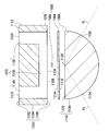
- 2 and 3 show the support structure of the first embodiment. 2 is a perspective view, and FIG. 3 is a cross-sectional view.
- the schematic diagram of FIG. 4 is a perspective view of the analysis chip of the first embodiment.
- the schematic diagram of FIG. 5 is an exploded sectional view of the analysis chip of the first embodiment.
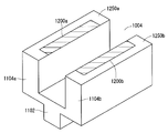
- the schematic diagram of FIG. 6 is a perspective view of the support body of 1st Embodiment.
- the measurement apparatus 1000 performs measurement by surface plasmon excitation fluorescence spectroscopy (SPFS).
- SPFS surface plasmon excitation fluorescence spectroscopy
- the measurement apparatus 1000 includes an analysis chip 1002, a support body 1004, a pressing mechanism 1006, a reagent chip 1008, a measurement mechanism 1010, a liquid feeding mechanism 1012, a light absorber 1014, a control unit 1016, and a display unit 1018.
- the analysis chip 1002 and the reagent chip 1008 are exchanged for each sample.
- the analysis chip 1002 is also called a sensor chip, an inspection chip, a sample cell, or the like.
- the measurement mechanism 1010 includes a laser diode unit 1020, a laser diode unit driving mechanism 1022, a first bandpass filter 1024, a low-pass filter 1026, a neutral density (ND) filter 1028, a half-wave plate 1030, a half-wave plate driving mechanism 1032, and a shaping.
- An optical system 1034, a condenser lens 1036, a second bandpass filter 1038, a bandpass filter driving mechanism 1040, an imaging lens 1042, and a photomultiplier tube (PMT) 1044 are provided.
- the first band-pass filter 1024, the low-pass filter 1026, the neutral density filter 1028, the half-wave plate 1030, and the shaping optical system 1034 constitute an excitation optical system 1046.
- the condenser lens 1036, the second band pass filter 1038, and the imaging lens 1042 constitute a detection optical system 1048.
- the laser diode unit 1020 includes a laser diode 1050, a posture holding mechanism 1052, a beam splitter 1054, a photodiode 1056, and a temperature adjustment circuit 1058.
- the liquid feed mechanism 1012 includes a liquid feed pump 1060 and a liquid feed pump drive mechanism 1062.
- the support structure 1100 includes an analysis chip 1002, a support body 1004, and a pressing mechanism 1006.
- the analysis chip 1002 includes a gold film 1064, a prism 1066, a capturing body 1068, and a flow path forming body 1070.
- the support body 1004 includes a base 1102 and support legs 1104a and 1104b.
- the analysis chip 1002 is supported by the support body 1004, the analysis chip 1002 is pressed against the support body 1004 by the pressing mechanism 1006, and the analysis chip 1002 is measured. Fixed to.
- the analysis chip 1002 is supported by the support 1004, the flow path forming body 1070 is supported by the support 1004, and the prism 1066 is separated from the support 1004.
- stress is not easily applied to the prism 1066, and birefringence is unlikely to occur in the prism 1066. Thereby, the polarization direction of the excitation light EL is hardly disturbed, and the sensitivity and accuracy of measurement are improved.
- the prism 1066 is not supported by the support body 1004, it is not necessary to provide a structure for supporting the prism 1066, and the shape of the prism 1066 is simplified.
- the simplification of the shape of the prism 1066 contributes to reducing unevenness in density during molding and making it difficult for birefringence to occur.
- the sample liquid 1092 is supplied to the flow path 1072 formed in the flow path forming body 1070 as shown in FIG.
- the antigen contained in the sample liquid 1092 is captured by the capturing body 1068, and the captured antigen is fluorescently labeled with the fluorescently labeled antibody contained in the sample liquid 1092.
- the excitation light EL is irradiated onto the prism 1066.
- the irradiated excitation light EL is reflected at the interface between the prism 1066 and the gold film 1064.
- the outer shape of the flow path forming body 1070 is a rectangular parallelepiped or a cube, and the surface 1101 of the flow path forming body 1070 has a flat upper surface 1102, a side surface 1104, and a lower surface 1106.
- a bonding area 1108 and an exposed area 1112 are provided on the surface 1101 of the flow path forming body 1070, and supported areas 1110a and 1110b are set.
- the bonding region 1108 is a region bonded to the first main surface 1114 of the gold film 1064 and occupies a part of the lower surface 1106.
- the exposed region 1112 is a region exposed to the outside of the analysis chip 1002 and occupies a part of the upper surface 1102 and the side surface 1104.
- the supported regions 1110 a and 1110 b are regions supported by the support body 1004 and occupy a part of the lower surface 1106. In FIG. 4, hatching is drawn in the supported regions 1110a and 1110b.
- the arrangement of the bonding region 1108, the exposed region 1112 and the supported regions 1110a and 1110b may be changed.
- the outer shape of the flow path forming body 1070 may be other than a rectangular parallelepiped and a cube.
- the bonding region 1108 and the supported regions 1110a and 1110b are provided in a concentrated manner on a flat surface facing a certain direction such as the lower surface 1106.
- the flat surface on which the bonding region 1108 is provided and the flat surface on which the supported regions 1110a and 1110b are set may face different directions.
- the external shape of the prism 1066 is a semi-cylindrical body, and the surface 1118 of the prism 1066 has a circumferential side surface 1120 and a flat side surface 1122.
- an incident area 1124, a reflection area 1126, and an emission area 1128 of the excitation light EL are set on the surface 1118 of the prism 1066.
- the incident area 1124 and the emission area 1128 occupy a part of the circumferential side surface 1120.
- the reflective region 1126 occupies a part of the flat side surface 1122.
- the incident area 1124, the reflection area 1126, and the emission area 1128 are arranged so that the excitation light EL incident on the incident area 1124 is totally reflected by the reflection area 1126 and emitted from the emission area 1128.
- the incident region 1124 occupies a part of the circumferential side surface 1120, the excitation light EL incident at different incident angles is collected, and the influence of the change in the resonance angle is less likely to appear.
- the entrance region 1124 and the exit region 1128 are arranged symmetrically.
- the s-polarized component of the reflected light is less likely to stay inside the prism 1066.
- the outer shape of the prism 1066 may be other than a semi-cylindrical body, and the prism 1066 may be replaced with a shape not included in the category of “prism”.
- the external shape of the prism 1066 may be a trapezoidal column, a plate, or the like.
- the capturing body 1068 is fixed to the first main surface 1114 of the gold film 1064.
- the first main surface 1114 of the gold film 1064 is bonded to the bonding region 1108.
- Second main surface 1116 of gold film 1064 is in close contact with reflection region 1126.
- the capturing body 1068 is accommodated in the flow path 1072. When the antigen is directly captured on the first main surface 1114 of the gold film 1064, the capturing body 1068 may be omitted.
- the gold film 1064 and the flow path forming body 1070 are bonded together by adhesion, laser welding, ultrasonic welding, clamp pressure bonding, or the like. However, the gold film 1064 and the flow path forming body 1070 may be joined by other methods.
- the gold film 1064 is formed in the reflective region 1126 by sputtering, vapor deposition, plating, or the like. However, the gold film 1064 may be formed by other methods.
- the flow path forming body 1070 is made of a material transparent to the surface plasmon excitation fluorescence FL.
- the flow path forming body 1070 is preferably made of resin and manufactured by injection molding.
- the thickness of the flow path forming body 1070 is desirably 1 to 10 mm. “Thickness” is a dimension in a direction perpendicular to the bonding region 1108. When the thickness is less than this range, the rigidity of the flow path forming body 1070 decreases, and it becomes difficult for the flow path forming body 1070 to receive stress. When the thickness exceeds this range, the time required for forming the flow path forming body 1070 becomes longer, and the manufacturing cost of the analysis chip increases.
- the prism 1066 is a dielectric medium made of a material transparent to the excitation light EL. Desirably, the prism 1066 is made of glass or resin having a refractive index of 1.4 to 1.6. When the prism 1066 is made of resin, the prism 1066 is desirably manufactured by injection molding. However, the prism 1066 may be manufactured by other methods. The material of the prism 1066 is desirably a resin that hardly causes birefringence. However, according to the support structure 1100 of the first embodiment, since stress is not easily applied to the prism 1066, even when the prism 1066 is made of a resin that easily generates birefringence, the accuracy and sensitivity of measurement are not easily lowered.
- the gold film 1064 is a thin film.
- the film thickness of the gold film 1064 is desirably 30 to 70 nm. However, the film thickness of the gold film 1064 may be outside this range.
- the gold film 1064 may be replaced with a film made of a conductor that generates surface plasmon resonance other than gold.
- the gold film 1064 may be replaced with a film made of a metal such as silver, copper, or aluminum, or an alloy containing these metals.
- a flow path 1072 is formed in the flow path forming body 1070.
- the channel 1072 extends from one sample solution inlet / outlet 1130 to the other sample solution inlet / outlet 1132 via the inside of the channel forming body 1070, and provides a sample solution storage space for storing the sample solution 1092.
- Sample liquid inlets / outlets 1130 and 1132 are provided in the exposed region 1112. As a result, the sample liquid 1092 can be supplied to the sample liquid inlets / outlets 1130 and 1132.
- the channel 1072 includes a surface exposed channel 1136 and internal through channels 1138 and 1140.
- the surface exposed flow path 1136 extends along the bonding region 1108 and has an opening 1134 in the bonding region 1108.
- One internal through channel 1138 extends from one sample liquid inlet / outlet port 1130 to one end of the surface exposed channel 1136.
- the other internal through channel 1140 extends from the other sample liquid inlet / outlet port 1132 to the other end of the surface exposed channel 1136.
- the number of sample liquid inlets / outlets may be increased to three or more.
- the channel 1072 may be replaced with a reservoir having one sample solution inlet / outlet.
- the flow path forming body 1070 is composed of one structure. However, the flow path forming body 1070 may be a combination of two or more structures. For example, the flow path forming body 1070 may be a combination of a seal in which the surface exposed flow path 1136 is formed and a block in which the internal through flow paths 1138 and 1140 are formed.
- the capturing body 1068 is made of a non-fluid body. Therefore, even if the sample liquid 1092 contacts the capturing body 1068, the capturing body 1068 does not move.
- the capturing body 1068 includes an antibody that binds to the antigen to be detected.
- the antibody is evenly distributed.
- the antigen to be detected contained in the sample liquid 1092 binds to the antibody contained in the capturing body 1068, and the detection target contained in the sample liquid 1092 is detected.
- the antigen is captured by the capturing body 1068.
- the capturing body 1068 is preferably fixed to the first main surface 1114 by surface treatment.
- the support body 1004 is a bifurcated branch body in which support legs 1104 a and 1104 b having a plate shape branch from the base 1102.
- the support legs 1104a and 1104b may have a shape other than the plate shape.
- the base 1102 is fixed inside the measurement apparatus 1000.
- the support legs 1104a and 1104b extend upward in the vertical direction from the base 1102. A part of the upper surface 1250a at the tip of the support leg 1104a and a part of the upper surface 1250b at the tip of the support leg 1104b become support regions 1200a and 1200b, respectively.
- the support body 1004 supports the analysis chip 1002
- the support areas 1200a and 1200b are in contact with the supported areas 1110a and 1110b, respectively.
- Support areas 1200a and 1200b are flat and at the same height.
- the support body 1004 has a shape that does not contact the prism 1066 when the analysis chip 1002 is supported. This makes it difficult for stress to be applied to the prism 1066, and makes it difficult for birefringence to occur in the prism 1066, improving the sensitivity and accuracy of measurement.
- the support 1004 has a shape that does not block the excitation light EL reflected by the excitation light EL and the reflection region 1126, that is, the reflected light RL, when the analysis chip 1002 is supported.
- the gap between one support leg 1104a and the other support leg 1104b is wider than the prism 1066 and narrower than the flow path forming body 1070.
- “Width” is a dimension in a direction perpendicular to the optical path of the excitation light EL.
- one supported region 1110 a is along one opposite side of the lower surface 1106, and the other supported region 1110 b is along the other opposite side of the lower surface 1106.
- the gold film 1064 is bonded between one supported region 1110a and the other supported region 1110b. Accordingly, the heavy prism 1066 is supported between the one supported region 1110a and the other supported region 1110b, and the flow path forming body 1070 is stably supported.
- the bonding region 1108 may be provided in another place.
- the number of support legs may be reduced to one, and the number of support areas and supported areas may be reduced to one.
- the number of support legs may be increased to 3 or more, and the number of support areas and supported areas may be increased to 3 or more.
- the pressing mechanism 1006 includes a pressing element 1142.
- the pressing mechanism 1006 applies the pressing element 1142 to the analysis chip 1002 and presses the analysis chip 1002 toward the support body 1004.
- the pressing element 1142 is preferably made of an elastic body such as rubber and contacts the upper surface 1102 of the flow path forming body 1070. Thereby, when the analysis chip 1002 is pressed, the flow path forming body 1070 is hardly damaged.
- the pressing mechanism 1006 may be omitted, and the analysis chip 1002 may simply be placed on the support body 1004.
- the pressing mechanism 1006 is disposed at a location that does not interfere with the surface plasmon excitation fluorescence FL.
- the excitation light EL is guided from the laser diode unit 1020 to the incident region 1124 by the excitation optical system 1046.
- the excitation light EL sequentially passes through the first bandpass filter 1024, the linear polarization filter 1026, the neutral density filter 1028, the half-wave plate 1030, and the shaping optical system 1034.
- the reflected light RL is absorbed by the light absorber 1014 provided in the vicinity of the emission region 1128. As a result, the reflected light RL is less likely to affect the measurement.
- the beam emitted from the laser diode 1050 is split into a main beam and a sub beam by the beam splitter 1054.
- the main beam becomes the excitation light EL.
- the cross-sectional shape of the excitation light EL beam is flat.
- the laser diode 1050 is oriented in such a posture that an elliptical short axis is included in a plane that includes the optical path of the excitation light EL and is perpendicular to the reflective region 1126. It is held by the holding mechanism 1052.
- the laser diode 1050 is desirably controlled by the temperature adjustment circuit 1058.
- the light amount of the sub beam is measured by the photodiode 1056, and the power supplied to the laser diode 1050 is regressively controlled by the temperature adjustment circuit 1058 so that the measurement result of the light amount of the sub beam is maintained constant.
- the temperature of the laser diode 1050 is kept constant, and the wavelength and light amount of the excitation light EL are kept constant.
- the photodiode 1056 may be replaced with another type of light amount sensor.
- the photodiode 1056 may be replaced with a phototransistor, a photoresistor, or the like. Since the wavelength of the excitation light EL affects the resonance angle and the amount of evanescent wave oozing, the temperature adjustment circuit 1058 contributes to the improvement of measurement accuracy and sensitivity.
- the laser diode 1050 may be replaced with another type of light source.
- the laser diode 1050 may be replaced with a light emitting diode, a mercury lamp, a laser other than the laser diode, or the like.
- the light emitted from the light source is not a beam
- the light is converted into a beam by a lens, a mirror, a slit, or the like.
- the light emitted from the light source is not monochromatic light
- the light is converted into monochromatic light by a diffraction grating or the like.
- the light emitted from the light source is not linearly polarized light
- the light is converted into linearly polarized light by a polarizer or the like.
- Second bandpass filter When the excitation light EL passes through the first bandpass filter 1024, the wavelength distribution of the excitation light EL is narrowed. Thereby, even if the wavelength distribution of the excitation light EL emitted from the laser diode unit 1020 is wide, the excitation light EL having a narrow wavelength distribution can be obtained. If the wavelength distribution of the excitation light EL emitted from the laser diode unit 1020 is sufficiently narrow, the first band pass filter 1024 may be omitted.
- Linear polarization filter When the excitation light EL passes through the linear polarization filter 1026, the distribution of the polarization direction of the excitation light EL is narrowed. Thereby, even if the distribution of the polarization direction of the excitation light EL emitted from the laser diode unit 1020 is wide, the excitation light EL having a narrow distribution of the polarization direction can be obtained. When the distribution of the polarization direction of the excitation light EL emitted from the laser diode unit 1020 is sufficiently narrow, the linear polarization filter 1026 may be omitted.
- the neutral density filter 1028 When the excitation light EL passes through the neutral density filter 1028, the light amount of the excitation light EL is decreased. If the amount of excitation light EL emitted from the laser diode unit 1020 is appropriate, the neutral density filter 1028 may be omitted.
- the half-wave plate 1030 is rotated around a rotation axis perpendicular to the half-wave plate 1030 by the half-wave plate driving mechanism 1032.
- the half-wave plate driving mechanism 1032 rotates the half-wave plate 1030 by a rotary stepping motor or the like.
- the polarization direction of the excitation light EL that passes through the half-wave plate 1030 is adjusted by the rotation angle of the half-wave plate 1030.
- the polarization direction of the excitation light EL can be adjusted between the polarization direction in which the bleeding of the evanescent wave from the reflection region 1126 is maximized and the polarization direction in which the bleeding of the evanescent wave from the reflection region 1126 is eliminated.
- the rotation angle of the half-wave plate 1030 is set to the rotation angle at which the p-polarized component is expected to be incident on the reflection region 1126.
- the half-wave plate driving mechanism 1032 may be replaced with a mechanism that rotates the laser diode 1050 or the laser diode unit 1020 around the optical axis.
- the half-wave plate driving mechanism 1032 may be omitted and the half-wave plate 1030 may be fixed.
- the optimization of the polarization direction described later is omitted and the laser diode 1050 or the laser diode unit 1020 is held in a posture in which the p-polarized component is mainly incident on the reflection region 1126, the half-wave plate 1030 and the half-wave plate drive are performed.
- the mechanism 1032 may be omitted.
- the beam size, cross-sectional shape, and the like of the excitation light EL are shaped by a slit, a zoom optical system, and the like.
- the surface plasmon excitation fluorescence FL is guided from the capturing body 1068 to the photomultiplier tube 1044 by the detection optical system 1048.
- the surface plasmon excitation fluorescence FL sequentially passes through the condenser lens 1036, the second bandpass filter 1038, and the imaging lens 1042.
- the condensing lens 1036 condenses the surface plasmon excitation fluorescence FL and converts it into parallel light.
- the imaging lens 1042 images the surface plasmon excitation fluorescence FL onto the photomultiplier tube 1044.
- the condensing lens 1036 and the imaging lens 1042 constitute a conjugate optical system. Thereby, the influence of stray light is suppressed.
- the second band pass filter 1038 is inserted into and removed from the optical path of the measurement light between the condenser lens 1036 and the imaging lens 1042 by the band pass filter driving mechanism 1040.
- Measurement light is scattered light of excitation light EL and surface plasmon excitation fluorescence FL.
- a second bandpass filter 1038 is inserted into the optical path of the measurement light, and the second bandpass filter 1038 selectively selects light having the same wavelength as the excitation light EL. Attenuated. Thereby, the scattered light is attenuated, and the surface plasmon excitation fluorescence FL is mainly guided to the photomultiplier tube 1044, and the sensitivity and accuracy of measurement are improved.
- the second bandpass filter 1038 is removed from the optical path of the measurement light.
- a neutral density filter may be inserted in and removed from the optical path of the measurement light.
- the neutral density filter is removed from the optical path of the measurement light.
- a neutral density filter is inserted into the optical path of the measurement light.
- the light amount of the surface plasmon excitation fluorescence FL may be measured by a relatively high sensitivity photomultiplier tube 1044, and the light amount of scattered light may be measured by a relatively low sensitivity photodiode, phototransistor, photoresistor, or the like.
- the amount of measurement light is measured by a photomultiplier tube 1044.
- the photomultiplier tube 1044 has the advantage of good sensitivity and signal-to-noise (S / N) ratio.
- the photomultiplier tube 1044 may be replaced with another type of light quantity sensor.
- the photomultiplier tube 1044 may be replaced with a cooled charge coupled device (CCD) camera or the like.
- CCD charge coupled device
- the liquid feeding pump 1060 sucks the liquid feeding object from the liquid feeding source and discharges it to the liquid feeding destination.
- the liquid feeding pump 1060 is conveyed from the liquid feeding source to the liquid feeding destination by the liquid feeding pump driving mechanism 1062.
- the liquid delivery object may be fed by a tube.
- the control unit 1016 is an embedded computer that executes software.
- One embedded computer may serve the function of the control unit 1016, or two or more embedded computers may share the function of the control unit 1016.
- Hardware without software may be responsible for all or part of the function of the control unit 1016.
- the hardware may be an electronic circuit such as an operational amplifier or a comparator, or may be a mechanical mechanism such as a link mechanism.
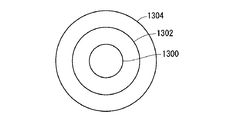
- the schematic diagram of FIG. 7 is a plan view showing a desirable relationship among the irradiation region 1300, the measurement region 1302, and the reaction region 1304 in the reflection region 1126.
- the irradiation region 1300 is a region where the excitation light EL is irradiated.
- the measurement region 1302 is a region where the amount of measurement light is measured by the photomultiplier tube 1044.
- the reaction region 1304 is a region where the capturing body 1068 is provided and the antigen-antibody reaction proceeds.
- the planar shapes of the irradiation region 1300 and the measurement region 1302 are preferably circular.
- the irradiation region 1300 is included in the measurement region 1302, and more desirably, the irradiation region 1300 is disposed in the center of the measurement region 1302. Thereby, even if the irradiation position is shifted due to the variation of the prism 1066 or the like, the irradiation region 1300 does not easily deviate from the measurement region 1302, and the amount of measurement light is maintained.
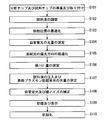
- the flowchart of FIG. 8 shows a measurement procedure.
- measurement is performed while the antigen-antibody reaction is in progress.
- an analysis chip 1002 and a reagent chip 1008 are prepared, and the analysis chip 1002 and the reagent chip 1008 are attached to the measuring device 1000 (step S101).
- the reagent chip 1008 is disposed in the pretreatment chamber.
- the specimen 1084 is stored in the specimen container 1073 of the reagent chip 1008 when the reagent chip 1008 is prepared.
- the specimen 1084 is typically a collected material from a human such as blood, but may be a collected material from a non-human organism or a non-living material.
- Diluent liquid 1086, fluorescent labeling liquid 1088, and cleaning liquid 1090 are previously stored in diluent container 1074, fluorescent labeling liquid container 1076, and cleaning liquid container 1078 of reagent chip 1008, respectively. It is planned that the sample liquid 1092 is accommodated in the dilution container 1082 of the reagent chip 1008.
- the specimen 1084 is sent from the specimen container 1073 to the dilution container 1082, and the dilution liquid 1086 is sent from the dilution liquid container 1074 to the dilution container 1082.
- the fluorescent labeling liquid 1088 is sent from the labeling liquid container 1076 to the dilution container 1082.
- the sample liquid 1092 is prepared in the dilution container 1082 (step S102). The components of the sample liquid 1092 may be changed.
- the dilution of the specimen 1084 may be omitted.
- other pretreatments such as blood cell separation and reagent mixing may be performed.
- the irradiation position is preferably optimized (step S103). However, the optimization of the irradiation position may be omitted. The irradiation position may be optimized before the sample liquid 1092 is prepared or in parallel with the sample liquid 1092 being prepared.
- the laser diode unit drive mechanism 1022 is controlled by the control unit 1016.
- the laser diode unit driving mechanism 1022 drives the laser diode unit 1020 to translate the excitation light EL.
- the irradiation position is scanned along a straight line.
- the amount of scattered light is measured by the photomultiplier tube 1044.
- the measurement result of the amount of scattered light is transferred to the control unit 1016.
- the second band-pass filter 1038 is removed from the optical path of the measurement light.
- a mirror that reflects the excitation light EL may be provided, and the irradiation position may be scanned by driving the mirror.
- the excitation optical system 1046 may be driven.
- the amount of scattered light is substantially constant. However, outside the section, the irradiation area 1300 deviates from the measurement area 1302, and the amount of scattered light decreases as the irradiation position moves away from the section.
- the control unit 1016 specifies first and second positions where the amount of scattered light decreases from the maximum value by the same value, and determines an intermediate position between the first and second positions.
- the laser diode unit driving mechanism 1022 moves the laser diode unit 1020 to a position intermediate between the first and second positions.
- the optical path length of the excitation light EL in the measurement region 1302 greatly affects the amount of autofluorescence, and the amount of autofluorescence changes as the irradiation position changes.
- the amount of autofluorescence is small compared to the amount of excitation light EL, but cannot be ignored compared to the amount of surface plasmon excitation fluorescence FL.
- measurement of the amount of light of the surface plasmon excitation fluorescence FL only affects autofluorescence emitted from the vicinity of the reflection region 1126.
- the optical path length of the excitation light EL in the measurement region 1302 is constant, the influence of the amount of autofluorescence is constant, and the measurement Sensitivity and accuracy are improved.
- optimization of an irradiation position is performed before measurement of the amount of autofluorescence. Thereby, the accuracy of measurement of the amount of autofluorescence is improved.
- the amount of autofluorescence is measured by the photomultiplier tube 1044 (step S104).
- the measurement result of the amount of autofluorescence is transferred to the control unit 1016 and stored in the control unit 1016.
- the half-wave plate driving mechanism 1032 is controlled by the control unit 1016.
- the half-wave plate driving mechanism 1032 drives the half-wave plate 1030 to rotate the polarization direction of the excitation light EL. Thereby, the polarization direction of the excitation light EL is scanned.
- the amount of scattered light is measured by the photomultiplier tube 1044 during scanning of the excitation light EL in the polarization direction.
- the measurement result of the amount of scattered light is transferred to the control unit 1016. While the amount of scattered light is being measured, the second band-pass filter 1038 is removed from the optical path of the measurement light.
- the control unit 1016 identifies the rotation angle at which the amount of scattered light is maximized.
- Half-wave plate driving mechanism 1032 rotates half-wave plate 1030 to a rotation angle at which the amount of scattered light is maximized.
- Birefringence that cannot be ignored occurs when light travels through a medium made of resin. This birefringence is caused by a change in the density of the medium depending on the position. Since the change in the density of the medium depending on the position occurs at the time of molding the resin, the birefringence strength differs for each prism 1066. For this reason, depending on the prism 1066, even if only the p-polarized light component that contributes to the exudation of the evanescent wave is incident on the reflection region 1126, the s-polarized light component is generated and the p-polarized light component is reduced. Decreases.
- the optimization of the polarization direction of the excitation light EL eliminates the decrease of the p-polarized component due to the dispersion of the prism 1066, and improves the measurement sensitivity and accuracy.
- the amount of dark noise is measured by the photomultiplier tube 1044 (step S106).
- the measurement result of the dark noise amount is transferred to the control unit 1016 and stored in the control unit 1016. While the amount of dark noise is being measured, the second band pass filter 1038 is inserted into the optical path of the measurement light.
- the sample liquid 1092 is injected into the flow path 1072.
- the light quantity of the surface plasmon excitation fluorescence FL is measured by the photomultiplier tube 1044 (step S107).
- the liquid feeding mechanism 1012 In the injection of the sample liquid 1092 into the flow path 1072, the liquid feeding mechanism 1012 is controlled by the control unit 1016.
- the liquid feeding mechanism 1012 sends the sample liquid 1092 from the dilution container 1082 to the flow path 1072.
- the antigen-antibody reaction proceeds, the antigen is captured by the capturing body 1068, and the captured antigen is fluorescently labeled on the fluorescently labeled antibody.
- the measurement result of the light amount of the surface plasmon excitation fluorescence FL during the antigen-antibody reaction is transferred to the control unit 1016 and stored in the control unit 1016. While the light quantity of the surface plasmon excitation fluorescence FL is being measured, the second bandpass filter 1038 is inserted into the optical path of the measurement light.
- the amount of light of the surface plasmon excitation fluorescence FL is measured in a state where the liquid feeding pump 1060 is inserted into the sample liquid inlet / outlet 1130 or 1132.
- the analysis chip 1002 is supported by the support body 1004, the stress applied from the liquid feed pump 1060 is received by the flow path forming body 1070, and no stress is applied to the prism 1066. Therefore, the support structure 1100 of the first embodiment is particularly suitable for measuring the light amount of the surface plasmon excitation fluorescence FL during the progress of the antigen-antibody reaction. However, the support structure 1100 of the first embodiment is also useful when the light amount of the surface plasmon excitation fluorescence FL is measured after completion of the antigen-antibody reaction.
- the control unit 1016 After the light amount of the surface plasmon excitation fluorescence FL is measured, the control unit 1016 performs correction to subtract the measurement result of the autofluorescence light amount and the measurement result of the dark noise amount from the measurement result of the light amount of the surface plasmon excitation fluorescence FL (step S108) Thereby, the influence of autofluorescence and dark noise is suppressed, and the sensitivity and accuracy of measurement are improved.
- the correction of the measurement result may be omitted. When the correction of the measurement result is omitted, the measurement of the amount of autofluorescence and the measurement of the amount of dark noise are also omitted.
- the corrected measurement result of the light amount of the surface plasmon excitation fluorescence FL is stored in the control unit 1016 together with the sample number and the like, and is displayed on the display unit 1018 together with the sample number and the like (step S109).
- the measurement result of the light amount of the surface plasmon excitation fluorescence FL is converted into the absolute amount, concentration, etc. of the antigen as necessary.
- the measuring apparatus 1000 After storing and displaying the measurement result, the measuring apparatus 1000 is initialized (step S110). In the initialization of the measuring apparatus 1000, a movable object such as the half-wave plate 1030 is returned to the initial position.
- the procedure executed by the measuring device 1000 may be executed manually, or the procedure executed manually may be executed by the measuring device 1000.
- the incident angle of the excitation light EL to the reflection region 1126 may be scanned near the resonance angle, and the incident angle may be optimized.
- the second embodiment relates to a support structure that is employed instead of the support structure of the first embodiment.
- FIG. 9 and 10 show the support structure of the second embodiment.
- FIG. 9 is a perspective view
- FIG. 10 is a cross-sectional view.
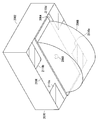
- the schematic diagram of FIG. 11 is a perspective view of the analysis chip of the second embodiment.
- the schematic diagram of FIG. 12 is a perspective view of the support body of 2nd Embodiment.
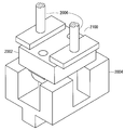
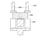
- the support structure 2100 of the second embodiment includes an analysis chip 2002, a support body 2004, and a pressing mechanism 2006.
- the analysis chip 2002 and the pressing mechanism 2006 of the second embodiment are the same as the analysis chip 1002 and the pressing mechanism 1006 of the first embodiment, respectively.
- the analysis chip 2002 of the second embodiment includes a gold film 2064, a prism 2066, a capturing body 2068, and a flow path forming body 2070.
- the gold film 2064, the prism 2066, the capturing body 2068, and the flow path forming body 2070 of the second embodiment are the same as the gold film 1064, the prism 1066, the capturing body 1068, and the flow path forming body 1070 of the first embodiment, respectively. is there.
- the analysis chip 2002 of the second embodiment is different from the analysis chip 1002 of the first embodiment in that the locations where the supported regions 2110a, 2110b, 2110c, and 2110d are set are different.
- the support body 2004 of the second embodiment includes a base 2102 and support legs 2104a, 2104b, 2104c, and 2104d.
- the base 2102 of the second embodiment is the same as the base 1102 of the first embodiment.
- the support body 2004 of the second embodiment is different from the support body 1004 of the first embodiment in that the support legs 1104a and 1104b are replaced with the support legs 2104a, 2104b, 2104c, and 2104d.
- the support body 2004 is a four-forked body in which support legs 2104 a, 2104 b, 2104 c, and 2104 d having a bar shape branch from the base 2102.
- the support legs 2104a, 2104b, 2104c, and 2104d extend upward in the vertical direction from the base 2102.
- the parts become support areas 2200a, 2200b, 2200c and 2200d, respectively.
- the support areas 2200a, 2200b, 2200c, and 2200d are in contact with the supported areas 2110a, 2110b, 2110c, and 2110d, respectively.
- Support regions 2200a, 2200b, 2200c and 2200d are flat and at the same height.
- the supported regions 2110 a, 2110 b, 2110 c, and 2110 d are in the vicinity of the four corners of the lower surface 2106.
- the support 2004 has a shape that does not contact the prism 2066 when the analysis chip 2002 is supported. This makes it difficult for stress to be applied to the prism 2066, making it difficult for birefringence to occur in the prism 2066, and improving the sensitivity and accuracy of measurement.
- the support 2004 has a shape that does not block the excitation light EL and the reflected light RL when the analysis chip 2002 is supported.
- the third embodiment relates to a support structure that is employed instead of the support structure of the first embodiment.
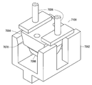
- FIG. 13 and 14 schematically show the support structure of the third embodiment.
- FIG. 13 is a perspective view
- FIG. 14 is a cross-sectional view.
- the schematic diagram of FIG. 15 is a perspective view of the analysis chip of the third embodiment.
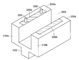
- the schematic diagram of FIG. 16 is a perspective view of the support body of 3rd Embodiment.
- the support structure 3100 of the third embodiment includes an analysis chip 3002, a support body 3004, and a pressing mechanism 3006.
- the pressing mechanism 3006 of the third embodiment is the same as the pressing mechanism 1006 of the first embodiment.
- the analysis chip 3002 of the third embodiment includes a gold film 3064, a prism 3066, a capturing body 3068, and a flow path forming body 3070.
- the gold film 3064, the prism 3066, and the capturing body 3068 of the third embodiment are the same as the gold film 1064, the prism 1066, and the capturing body 1068 of the first embodiment, respectively.
- the flow path forming body 3070 of the third embodiment is different from the flow path forming body 1070 of the first embodiment in that positioning holes 3304 and 3306 are formed.
- the support body 3004 of the third embodiment includes a base 3102, support legs 3104 a and 3104 b, and positioning pins 3300 and 3302.
- the base 3102 and the support legs 3104a and 3104b of the third embodiment are the same as the base 1102 and the support legs 1104a and 1104b of the first embodiment, respectively.
- the support body 3004 of the third embodiment is different from the support body 1004 of the first embodiment in that positioning pins 3300 and 3302 are further provided.
- a part of the upper surface 3250a at the tip of the support leg 3104a and a part of the upper surface 3250b at the tip of the support leg 3104b become support regions 3200a and 3200b, respectively.
- the support 3004 supports the analysis chip 3002
- the support regions 3200a and 3200b are in contact with the supported regions 3110a and 3110b, respectively.
- the support 3004 has a shape that does not contact the prism 3066 when the analysis chip 3002 is supported. This makes it difficult for stress to be applied to the prism 3066, and makes it difficult for birefringence to occur in the prism 3066, improving the sensitivity and accuracy of measurement.
- the support 3004 has a shape that does not block the excitation light EL and the reflected light RL when the analysis chip 3002 is supported.
- the positioning pins 3300 and 3302 protrude from the support region 3200a and extend perpendicular to the support region 3200a.
- the positioning pins 3300 and 3302 are inserted into the positioning holes 3304 and 3306, respectively.
- the positioning pins 3300 and 3302 restrict the movement of the flow path forming body 3070 in the direction parallel to the joining region 3108, the position of the flow path forming body 3070 is determined, and the prism 3066 is disposed at an appropriate position.
- the positioning pins 3300 and 3302 may be replaced with other types of positioning structures.
- the fourth embodiment relates to a support structure that is employed instead of the support structure of the first embodiment.
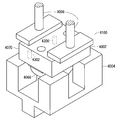
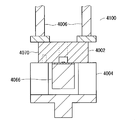
- FIG. 17 and 18 schematically show the support structure of the fourth embodiment.
- 17 is a perspective view
- FIG. 18 is a cross-sectional view.
- the schematic diagram of FIG. 19 is a perspective view of the analysis chip of the fourth embodiment.
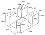
- the schematic diagram of FIG. 20 is a perspective view of the support body of 4th Embodiment.
- the support structure 4100 of the fourth embodiment includes an analysis chip 4002, a support 4004, and a pressing mechanism 4006.
- the pressing mechanism 4006 of the fourth embodiment is the same as the pressing mechanism 1006 of the first embodiment.
- the analysis chip 4002 of the fourth embodiment includes a gold film 4064, a prism 4066, a capturing body 4068, and a flow path forming body 4070.
- the gold film 4064, the prism 4066, and the capturing body 4068 of the fourth embodiment are the same as the gold film 1064, the prism 1066, and the capturing body 1068 of the first embodiment, respectively.
- the flow path forming body 4070 of the fourth embodiment is different from that of the first embodiment in that the positions where the supported regions 4110a, 4110b, 4110c and 4110d are set are changed and the positioning holes 4304 and 4306 are formed. Different from the body 1070.
- the support body 4004 includes a base 4102, support legs 4104a, 4104b, 4104c and 4104d, and positioning pins 4300 and 4302.
- the base 4102 of the fourth embodiment is the same as the base 1102 of the first embodiment.
- the support 4004 of the fourth embodiment is provided with support legs 4104a, 4104b, 4104c and 4104d instead of the support legs 1104a and 1104b, and further provided with positioning pins 4300 and 4302. Is different.
- the support body 4004 is a four-forked body in which support legs 4104a, 4104b, 4104c, and 4104d having a bar shape are branched from the base 4102.
- the support legs 4104a, 4104b, 4104c, and 4104d extend upward in the vertical direction from the base 4102.
- the parts become support areas 4200a, 4200b, 4200c and 4200d, respectively.
- the support areas 4200a, 4200b, 4200c, and 4200d are in contact with the supported areas 4110a, 4110b, 4110c, and 4110d, respectively.
- the support 4004 has a shape that does not contact the prism 4066 when the analysis chip 4002 is supported. This makes it difficult for stress to be applied to the prism 4066, and makes it difficult for birefringence to occur in the prism 4066, improving the sensitivity and accuracy of measurement.
- the support 4004 has a shape that does not block the excitation light EL and the reflected light RL when the analysis chip 4002 is supported.
- the positioning pins 4300 and 4302 protrude from the support areas 4200a and 4200b, respectively, and extend perpendicularly to the support areas 4200a and 4200b.
- the positioning pins 4300 and 4302 are inserted into the positioning holes 4304 and 4306, respectively. Thereby, the position of the flow path forming body 4070 is determined, and the prism 4066 is arranged at an appropriate position.
- the fifth embodiment relates to a support structure that is employed instead of the support structure of the first embodiment.
- FIG. 21 and 22 show the support structure of the fifth embodiment.
- FIG. 21 is a perspective view
- FIG. 22 is a cross-sectional view.
- the schematic diagram of FIG. 23 is a perspective view of the analysis chip of the fifth embodiment.
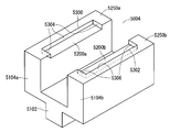
- the schematic diagram of FIG. 24 is a perspective view of the support body of 5th Embodiment.
- the support structure 5100 of the fifth embodiment includes an analysis chip 5002, a support 5004, and a pressing mechanism 5006.
- the analysis chip 5002 and the pressing mechanism 5006 of the third embodiment are the same as the analysis chip 1002 and the pressing mechanism 1006 of the first embodiment.
- the analysis chip 5002 of the fifth embodiment includes a gold film 5064, a prism 5066, a capturing body 5068, and a flow path forming body 5070.
- the gold film 5064, the prism 5066, the capturing body 5068, and the flow path forming body 5070 of the fifth embodiment are the same as the gold film 1064, the prism 1066, the capturing body 1068, and the flow path forming body 1070 of the first embodiment, respectively. is there.
- the analysis chip 5002 of the fifth embodiment is different from the analysis chip 1002 of the first embodiment in that the regulated regions 5306 and 5308 are set on the surface 5101.
- the support 5004 of the fifth embodiment includes a base 5102 and support legs 5104a and 5104b.
- the base 5102 of the fifth embodiment is the same as the base 1102 of the first embodiment.
- the support 5004 of the fifth embodiment is different from the support 1004 of the first embodiment in that positioning grooves 5300 and 5302 are formed.
- the support body 5004 is a bifurcated branch body in which support legs 5104 a and 5104 b having a plate shape branch from the base 5102. Positioning grooves 5300 and 5302 are formed on the upper surface 5250b of the upper surfaces 5250a and 5104b at the distal ends of the support legs 5104a, respectively.
- the flow path forming body 5070 is accommodated in the positioning grooves 5300 and 5302.
- the entire bottom surface of the positioning groove 5300 and the entire bottom surface of the positioning groove 5302 become support regions 5200a and 5200b, respectively.
- the support 5004 supports the analysis chip 5002
- the support regions 5200a and 5200b are in contact with the supported regions 5110a and 5110b, respectively.
- the support 5004 has a shape that does not contact the prism 5066 when the analysis chip 5002 is supported. This makes it difficult for stress to be applied to the prism 5066, making it difficult for birefringence to occur in the prism 5066, and improving the sensitivity and accuracy of measurement.
- the support 5004 has a shape that does not block the excitation light EL and the reflected light RL when the analysis chip 5002 is supported.
- the entire side surface of the positioning groove 5300 and the entire side surface of the positioning groove 5302 become restriction regions 5304 and 5306, respectively.
- the restriction regions 5304 and 5306 are in contact with the restricted regions 5306 and 5308, respectively.
- the positioning grooves 5300 and 5302 restrict the movement of the flow path forming body 5070 in the direction parallel to the bonding region 5108, the position of the flow path forming body 5070 is determined, and the prism 5066 is disposed at an appropriate position.
- the positioning grooves 5300 and 5302 restrict the movement of the flow path forming body 5070 in both the direction perpendicular to and parallel to the support legs 5104a and 5104b, but in the direction perpendicular to and parallel to the support legs 5104a and 5104b. It is also permitted to restrict the movement of the flow path forming body 5070 to only one side.
- the sixth embodiment relates to a support structure that is employed instead of the support structure of the first embodiment.
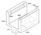
- FIG. 25 and FIG. 26 are schematic views showing the support structure of the sixth embodiment. 25 is a perspective view, and FIG. 26 is a cross-sectional view.
- the schematic diagram of FIG. 27 is a perspective view of the analysis chip of the sixth embodiment.
- the schematic diagram of FIG. 28 is a perspective view of the support body of 6th Embodiment.
- the support structure 6100 of the sixth embodiment includes an analysis chip 6002, a support 6004, and a pressing mechanism 6006.
- the pressing mechanism 6006 of the sixth embodiment is the same as the pressing mechanism 1006 of the first embodiment.
- the analysis chip 6002 of the sixth embodiment includes a gold film 6064, a prism 6066, a capturing body 6068, and a flow path forming body 6070.
- the gold film 6064, the prism 6066, and the capturing body 6068 of the sixth embodiment are the same as the gold film 1064, the prism 1066, and the capturing body 1068 of the first embodiment, respectively.
- the outer shape is changed from a rectangular parallelepiped to an isosceles trapezoidal column, and the place where the supported regions 6110a and 6110b are set is changed from the lower surface to the inclined side surfaces 6104a and 6104b. This is different from the flow path forming body 1070 of the first embodiment.
- the support body 6004 of the sixth embodiment includes a base 6102 and support legs 6104a and 6104b.
- the base 6102 of the sixth embodiment is the same as the base 1102 of the first embodiment.
- the support legs 6104a and 6104b of the sixth embodiment are changed so that the outer shape has inclined side surfaces 6250a and 6250b, respectively, and the place where the support regions 6200a and 6200b are set is changed from the upper surface to the inclined side surfaces 6250a and 6250b, respectively. This is different from the support legs 1004a and 1004b of the first embodiment.
- the support body 6004 is a bifurcated branch body in which support legs 6104 a and 6104 b having a plate shape branch from the base 6102. A part of the inclined side surface 6250a of the support leg 6104a and a part of the inclined side surface 6250b of the support leg 6104b become support regions 6200a and 6200b, respectively.
- the support region 6200a may occupy the entire inclined side surface 6250a, and the support region 6200b may occupy the entire inclined side surface 6250b.
- the support 6004 supports the analysis chip 6002
- the support regions 6200a and 6200b are in contact with the supported regions 6110a and 6110b, respectively.
- the surface 6101 of the flow path forming body 6070 has flat inclined side surfaces 6104a and 6104b and a lower surface 6106.
- the inclined side surfaces 6104 a and 6104 b are inclined from a direction perpendicular to the lower surface 6106. The interval between one inclined side surface 6104a and the other inclined side surface 6104b becomes narrower as the lower surface 6106 is approached.
- the supported regions 6110a and 6110b occupy part of the inclined side surfaces 6104a and 6104b, respectively.
- the supported regions 6110a and 6110b may occupy the entire inclined side surfaces 6104a and 6104b, respectively.
- the support 6004 has a shape that does not contact the prism 6066 when the analysis chip 6002 is supported. This makes it difficult for stress to be applied to the prism 6066, and makes it difficult for birefringence to occur in the prism 6066, improving the sensitivity and accuracy of measurement.
- the support 6004 has a shape that does not block the excitation light EL and the reflected light RL when the analysis chip 6002 is supported.
- the movement of the flow path forming body 6070 in the direction parallel to the joining region is restricted, the position of the flow path forming body 6070 is determined, and the prism 6066 is disposed at an appropriate position. Is done. This is because the supported regions 6110a and 6110b are set on the inclined side surfaces 6104a and 6104b.
- the seventh embodiment relates to a support structure that is employed instead of the support structure of the first embodiment.
- FIG. 29 and 30 schematically show the support structure of the seventh embodiment.
- 29 is a perspective view
- FIG. 30 is a cross-sectional view.
- the schematic diagram of FIG. 31 is a perspective view of the analysis chip of 7th Embodiment.
- the schematic diagram of FIG. 32 is a perspective view of the support body of 7th Embodiment.
- the support structure 7100 of the seventh embodiment includes an analysis chip 7002, a support 7004, and a pressing mechanism 7006.
- the pressing mechanism 7006 of the seventh embodiment is the same as the pressing mechanism 1006 of the first embodiment.
- the analysis chip 7002 of the seventh embodiment includes a gold film 7064, a prism 7066, a capturing body 7068, and a flow path forming body 7070.
- the gold film 7064, the prism 7066, and the capturing body 7068 of the seventh embodiment are the same as the gold film 1064, the prism 1066, and the capturing body 1068 of the first embodiment, respectively.
- the outer shape is changed from a rectangular parallelepiped to an isosceles trapezoidal column, and the place where the supported regions 7110a, 7110b, 7110c and 7110d are set is changed from the lower surface to the inclined side surfaces 7104a and 7104b. It differs from the flow path forming body 1070 of the first embodiment in that it is changed.
- the support body 7004 of the seventh embodiment includes a base 7102 and support legs 7104a, 7104b, 7104c, and 7104b.
- the base 7102 of the seventh embodiment is the same as the base 1102 of the first embodiment.
- the support 7002 of the seventh embodiment is changed to support legs 7104a, 7104b, 7104c and 7104d in which the support legs 1104a and 1104b have inclined side surfaces 7250a, 7250b, 7250c and 7250d, and the support regions 7200a, 7200b, 7200c and 7200d are changed. It differs from the flow path forming body 1070 of the first embodiment in that the place to be set is changed from the upper surface to the inclined side surfaces 7250a, 7250b, 7250c and 7250d.
- the support body 7004 is a four-forked body in which support legs 7104a, 7104b, 7104c, and 7104d having a bar shape are branched from the base 7102.
- a part of the inclined side surface 7250a of the support leg 7104a, a part of the inclined side surface 7250b of the support leg 7104b, a part of the inclined side surface 7250c of the support leg 7104c, and a part of the inclined side surface 7250d of the support leg 7104d are respectively supported regions 7200a. 7200b, 7200c, and 7200d.
- the support regions 7200a, 7200b, 7200c, and 7200d may occupy the entire inclined side surfaces 7250a, 7250b, 7250c, and 7250d, respectively.
- the support regions 7200a, 7200b, 7200c, and 7200d are in contact with the supported regions 7110a, 7110b, 7110c, and 7110d, respectively.
- the surface 7101 of the flow path forming body 7070 has flat inclined side surfaces 7104a and 7104b and a lower surface 7106.
- the inclined side surfaces 7104 a and 7104 b are inclined from a direction perpendicular to the lower surface 7106. The distance between one inclined side surface 7104a and the other inclined side surface 7104b becomes narrower as the lower surface 7106 is approached.
- the supported regions 7110a and 7110b occupy a part of the inclined side surface 7104a, and the supported regions 7110c and 7110d occupy a part of the inclined side surface 7104b.
- the support 7004 has a shape that does not contact the prism 7066 when the analysis chip 7002 is supported. This makes it difficult for stress to be applied to the prism 7066 and makes it difficult for birefringence to occur in the prism 7066, improving the sensitivity and accuracy of measurement.
- the support 7004 has a shape that does not block the excitation light EL and the reflected light RL when the analysis chip 7002 is supported.
- the movement of the flow path forming body 7070 in the direction parallel to the joining region is restricted, the position of the flow path forming body 7070 is determined, and the prism 7066 is disposed at an appropriate position. Is done. This is because the supported regions 7110a, 7110b, 7110c, and 7110d are set on the inclined side surfaces 7104a and 7104b.
Landscapes
- Health & Medical Sciences (AREA)
- Nuclear Medicine, Radiotherapy & Molecular Imaging (AREA)
- Physics & Mathematics (AREA)
- Life Sciences & Earth Sciences (AREA)
- Chemical & Material Sciences (AREA)
- Analytical Chemistry (AREA)
- Biochemistry (AREA)
- General Health & Medical Sciences (AREA)
- General Physics & Mathematics (AREA)
- Immunology (AREA)
- Pathology (AREA)
- Investigating, Analyzing Materials By Fluorescence Or Luminescence (AREA)
- Investigating Or Analysing Materials By Optical Means (AREA)
Abstract
計測の感度及び精度が向上する支持構造及び計測装置を提供する。分析チップは、流路成形体、プリズム及び金膜を備える。流路形成体には、流路が形成される。分析チップは、支持体に支持される。支持体が分析チップを支持する場合には、流路形成体が支持体に支持され、プリズムは支持体に接触しない。プリズムの表面の入射領域、反射領域及び出射領域は、入射領域へ入射した励起光が反射領域に全反射され出射領域から出射するように配置される。金膜の第1の主面は、流路形成体の表面の接合領域に接合される。金膜の第2の主面は、プリズムの表面の反射領域に密着する。
Description
本発明は、表面プラズモン励起蛍光分光法による計測を行う計測装置及び当該計測装置における支持構造に関する。
誘電体媒体の中を進む励起光が金属膜と誘電体媒体との界面に反射された場合は、界面からエバネッセント波がもれだし、金属膜の表面のプラズモンとエバネッセント波とが干渉する。界面への励起光の入射角が共鳴角に設定されプラズモンとエバネッセント波とが共鳴する場合にエバネッセント波の電場が著しく増強される。
表面プラズモン励起蛍光分光法(SPFS)においては、この増強された電場が利用される。すなわち、金属膜の表面に抗原が捕捉され、捕捉された抗原が蛍光標識され、増強された電場が蛍光標識に作用させられる。増強された電場が蛍光標識に作用した場合は、蛍光標識から蛍光が放射され、蛍光標識から放射された蛍光の光量が測定される。
界面からもれだすエバネッセント波は、金属膜と誘電体媒体との界面へ入射する励起光のp偏光成分が多くなるほど強くなる。また、金属膜と誘電体媒体との界面へ入射する励起光のs偏光成分は、表面プラズモン励起蛍光の放射に寄与せず、誘電体媒体の自家蛍光の原因になる。このため、計測の感度及び精度を向上するために、金属膜と誘電体媒体との界面へ専らp偏光成分が入射するように誘電体媒体に照射される励起光の偏光成分が調整される。
一方、SPFSによる計測が行われる場合は、一般的には、誘電体媒体を備える分析チップが計測装置の内部に支持される。特許文献1は、その一例である。特許文献1においては、誘電体媒体である「透明板17」が「押圧子26、27」に挟まれる。
しかし、特許文献1のように誘電体媒体に応力が加わると、誘電体媒体に複屈折が生じ、金属膜と誘電体媒体との界面に入射する励起光の偏光方向が乱れる。このため、金属膜と誘電体媒体との界面へ入射する励起光のp偏光成分が減少し、計測の精度及び感度が低下する。
本発明は、この問題を解決するためになされる。本発明の目的は、計測の感度及び精度が向上する支持構造及び計測装置を提供することである。
本発明の第1から第6までの局面は、表面プラズモン励起蛍光分光法による計測を行う計測装置における支持構造に関する。
本発明の第1の局面においては、支持構造は、構造物、誘電体媒体、導電体膜及び支持体を備える。構造物の表面は、接合領域及び被支持領域を有する。構造物には、試料収容空間が形成される。試料収容空間は、接合領域に開口を有する。誘電体媒体の表面は、入射領域、反射領域及び出射領域を有する。入射領域へ入射した励起光が反射領域に全反射され出射領域から出射するように入射領域、反射領域及び出射領域が配置される。導電体膜の第1の主面は、接合領域に接合される。導電体膜の第2の主面は、反射領域に密着する。支持体の支持領域は、被支持領域に接触する。支持領域が被支持領域に接触する場合に支持体は誘電体媒体から離れる。
本発明の第2の局面は、本発明の第1の局面にさらなる事項を付加する。本発明の第2の局面においては、構造物の表面が平坦面を有する。被支持領域及び接合領域は、平坦面に設けられる。
本発明の第3の局面は、本発明の第2の局面にさらなる事項を付加する。本発明の第3の局面においては、接合領域に平行な方向への構造物の移動を規制する位置決め構造が支持体に設けられる。
本発明の第4の局面は、本発明の第3の局面にさらなる事項を付加する。本発明の第4の局面においては、支持領域から突出し支持領域に垂直に延在する位置決めピンが支持体に設けられる。支持領域が被支持領域に接触する場合に位置決めピンが挿入される位置決め孔が構造物に形成される。
本発明の第5の局面は、本発明の第3の局面にさらなる事項を付加する。本発明の第5の局面においては、位置決め構造が構造物を収容する位置決め溝である。
本発明の第6の局面は、本発明の第1の局面にさらなる事項を付加する。本発明の第6の局面においては、構造物の表面が第1の平坦面、第2の平坦面及び第3の平坦面を有する。第2の平坦面及び第3の平坦面は、第1の平坦面に垂直な方向から傾斜する。第2の平坦面と第3の平坦面との間隔は、第1の平坦面へ近づくにつれて狭くなる。上記の被支持領域は第1の被支持領域であり、構造物の表面は第2の被支持領域を有する。上記の支持領域は第1の支持領域であり、支持体は第2の支持領域を有する。第1の被支持領域は第2の平坦面にある。第2の被支持領域は第3の平坦面にある。接合領域は、第1の平坦面にある。第2の支持領域は、第2の被支持領域に接触する。
本発明の第7の局面は、表面プラズモン励起蛍光分光法による計測を行う計測装置に関する。本発明の第7の局面においては、測定機構及び本発明の第1の局面の支持構造が設けられる。測定機構は、入射面へ励起光を入射させ、表面プラズモン励起蛍光分光法による測定を行う。
本発明の第1及び第7の局面によれば、誘電体媒体に加わる応力が減り、計測の感度及び精度が向上する。
本発明の第3から第6までの局面によれば、構造物の位置が決まり、誘電体媒体が適切な位置に配置される。
これらの及びこれら以外の本発明の目的、特徴、局面及び利点は、添付図面とともに考慮されたときに下記の本発明の詳細な説明によってより明白となる。
{第1実施形態}
(計測装置の概略)
第1実施形態は、計測装置及び支持構造に関する。
(計測装置の概略)
第1実施形態は、計測装置及び支持構造に関する。
図1の模式図は、第1実施形態の計測装置を示す。図2及び図3の模式図は、第1実施形態の支持構造を示す。図2は斜視図であり、図3は断面図である。図4の模式図は、第1実施形態の分析チップの斜視図である。図5の模式図は、第1実施形態の分析チップの分解断面図である。図6の模式図は、第1実施形態の支持体の斜視図である。
第1実施形態の計測装置1000は、表面プラズモン励起蛍光分光法(SPFS)により計測を行う。
図1に示すように、計測装置1000は、分析チップ1002、支持体1004、押圧機構1006、試薬チップ1008、測定機構1010、送液機構1012、光吸収体1014、制御部1016及び表示部1018を備える。分析チップ1002及び試薬チップ1008は検体ごとに交換される。分析チップ1002は、センサーチップ、検査チップ、試料セル等とも呼ばれる。
測定機構1010は、レーザーダイオードユニット1020、レーザーダイオードユニット駆動機構1022、第1のバンドバスフィルタ1024、ローパスフィルタ1026、減光(ND)フィルタ1028、半波長板1030、半波長板駆動機構1032、整形光学系1034、集光レンズ1036、第2のバンドパスフィルタ1038、バンドパスフィルタ駆動機構1040、結像レンズ1042及び光電子増倍管(PMT)1044を備える。
第1のバンドバスフィルタ1024、ローパスフィルタ1026、減光フィルタ1028、半波長板1030及び整形光学系1034は、励起光学系1046を構成する。集光レンズ1036、第2のバンドパスフィルタ1038及び結像レンズ1042は、検出光学系1048を構成する。
レーザーダイオードユニット1020は、レーザーダイオード1050、姿勢保持機構1052、ビームスプリッタ1054、フォトダイオード1056及び温度調整回路1058を備える。
送液機構1012は、送液ポンプ1060及び送液ポンプ駆動機構1062を備える。
図2及び図3に示すように、第1実施形態の支持構造1100は、分析チップ1002、支持体1004及び押圧機構1006を備える。
図4及び図5に示すように、分析チップ1002は、金膜1064、プリズム1066、捕捉体1068及び流路形成体1070を備える。
図6に示すように、支持体1004は、基台1102並びに支持脚1104a及び1104bを備える。
(計測の概略)
計測が行われる場合には、図2及び図3に示すように、分析チップ1002が支持体1004に支持され、押圧機構1006により分析チップ1002が支持体1004へ押し付けられ、分析チップ1002が測定位置に固定される。分析チップ1002が支持体1004に支持される場合には、流路形成体1070が支持体1004に支持され、プリズム1066は支持体1004から離れる。プリズム1066が支持体1004に接触しない場合は、プリズム1066に応力が加わりにくく、プリズム1066に複屈折が生じにくい。これにより、励起光ELの偏光方向が乱れにくくなり、計測の感度及び精度が向上する。また、プリズム1066を支持体1004で支持しない場合は、プリズム1066に支持のための構造を設ける必要がなくなり、プリズム1066の形状が簡略化される。プリズム1066の形状の簡略化は、成形のときの密度のむらを減らし、複屈折を生じにくくすることに寄与する。
計測が行われる場合には、図2及び図3に示すように、分析チップ1002が支持体1004に支持され、押圧機構1006により分析チップ1002が支持体1004へ押し付けられ、分析チップ1002が測定位置に固定される。分析チップ1002が支持体1004に支持される場合には、流路形成体1070が支持体1004に支持され、プリズム1066は支持体1004から離れる。プリズム1066が支持体1004に接触しない場合は、プリズム1066に応力が加わりにくく、プリズム1066に複屈折が生じにくい。これにより、励起光ELの偏光方向が乱れにくくなり、計測の感度及び精度が向上する。また、プリズム1066を支持体1004で支持しない場合は、プリズム1066に支持のための構造を設ける必要がなくなり、プリズム1066の形状が簡略化される。プリズム1066の形状の簡略化は、成形のときの密度のむらを減らし、複屈折を生じにくくすることに寄与する。
分析チップ1002が支持体1004に支持された状態において、図1に示すように、流路形成体1070に形成された流路1072へ試料液1092が供給される。抗原抗体反応により、試料液1092に含まれる抗原が捕捉体1068に捕捉され、捕捉された抗原が試料液1092に含まれる蛍光標識抗体により蛍光標識される。
抗原抗体反応と並行して、励起光ELがプリズム1066に照射される。照射された励起光ELは、プリズム1066と金膜1064との界面で反射される。
プリズム1066と金膜1064との界面で励起光ELが反射される場合は、金膜1064とプリズム1066との界面から金膜1064の側にエバネッセント波がもれだし、金膜1064の表面のプラズモンとエバネッセント波とが干渉する。プラズモンとエバネッセント波とが共鳴する場合にエバネッセント波の電場は著しく増強される。増強された電場は蛍光標識を励起し、蛍光標識から表面プラズモン励起蛍光FLが放射される。表面プラズモン励起蛍光FLの光量は、光電子増倍管1044により測定される。光電子増倍管1044の測定結果から抗原の有無、抗原の捕捉量等が制御部1016により算出され、算出結果が表示部1018に表示される。
(流路形成体の形状)
図4及び図5に示すように、流路形成体1070の外形形状は直方体又は立方体であり、流路形成体1070の表面1101は、平坦な上面1102、側面1104及び下面1106を有する。流路形成体1070の表面1101には、接合領域1108及び露出領域1112が設けられ、被支持領域1110a及び1110bが設定される。接合領域1108は、金膜1064の第1の主面1114に接合される領域であり、下面1106の一部を占める。露出領域1112は、分析チップ1002の外部に露出する領域であり、上面1102の一部及び側面1104を占める。被支持領域1110a及び1110bは、支持体1004に支持される領域であり、下面1106の一部を占める。図4においては、被支持領域1110a及び1110bにハッチングが描かれる。接合領域1108、露出領域1112並びに被支持領域1110a及び1110bの配置が変更されてもよい。流路形成体1070の外形形状が直方体及び立方体以外であってもよい。流路形成体1070の外形形状が直方体及び立方体以外である場合は、下面1106のような一定方向を向く平坦面に接合領域1108並びに被支持領域1110a及び1110bが集中して設けられる。接合領域1108が設けられる平坦面と被支持領域1110a及び1110bが設定される平坦面とが異なる方向を向いてもよい。
図4及び図5に示すように、流路形成体1070の外形形状は直方体又は立方体であり、流路形成体1070の表面1101は、平坦な上面1102、側面1104及び下面1106を有する。流路形成体1070の表面1101には、接合領域1108及び露出領域1112が設けられ、被支持領域1110a及び1110bが設定される。接合領域1108は、金膜1064の第1の主面1114に接合される領域であり、下面1106の一部を占める。露出領域1112は、分析チップ1002の外部に露出する領域であり、上面1102の一部及び側面1104を占める。被支持領域1110a及び1110bは、支持体1004に支持される領域であり、下面1106の一部を占める。図4においては、被支持領域1110a及び1110bにハッチングが描かれる。接合領域1108、露出領域1112並びに被支持領域1110a及び1110bの配置が変更されてもよい。流路形成体1070の外形形状が直方体及び立方体以外であってもよい。流路形成体1070の外形形状が直方体及び立方体以外である場合は、下面1106のような一定方向を向く平坦面に接合領域1108並びに被支持領域1110a及び1110bが集中して設けられる。接合領域1108が設けられる平坦面と被支持領域1110a及び1110bが設定される平坦面とが異なる方向を向いてもよい。
(プリズムの形状)
プリズム1066の外形形状は半円柱体であり、プリズム1066の表面1118は、円周側面1120及び平坦側面1122を有する。プリズム1066の表面1118には、励起光ELの入射領域1124、反射領域1126及び出射領域1128が設定される。入射領域1124及び出射領域1128は、円周側面1120の一部を占める。反射領域1126は、平坦側面1122の一部を占める。入射領域1124、反射領域1126及び出射領域1128は、入射領域1124へ入射した励起光ELが反射領域1126に全反射され出射領域1128から出射するように配置される。入射領域1124が円周側面1120の一部を占める場合は、異なる入射角で入射した励起光ELが集光され、共鳴角の変化の影響が現れにくくなる。
プリズム1066の外形形状は半円柱体であり、プリズム1066の表面1118は、円周側面1120及び平坦側面1122を有する。プリズム1066の表面1118には、励起光ELの入射領域1124、反射領域1126及び出射領域1128が設定される。入射領域1124及び出射領域1128は、円周側面1120の一部を占める。反射領域1126は、平坦側面1122の一部を占める。入射領域1124、反射領域1126及び出射領域1128は、入射領域1124へ入射した励起光ELが反射領域1126に全反射され出射領域1128から出射するように配置される。入射領域1124が円周側面1120の一部を占める場合は、異なる入射角で入射した励起光ELが集光され、共鳴角の変化の影響が現れにくくなる。
望ましくは、入射領域1124及び出射領域1128は対称に配置される。これにより、反射光のs偏光成分がプリズム1066の内部に滞留しにくくなる。
共鳴角で励起光ELが反射領域1126へ入射する限り、プリズム1066の外形形状が半円柱体以外でもよく、プリズム1066が「プリズム」の範疇に含まれない形状物に置きかえられてもよい。例えば、プリズム1066の外形形状が、台形柱体、板等であってもよい。
(分析チップの全体)
金膜1064の第1の主面1114には、捕捉体1068が定着する。金膜1064の第1の主面1114は、接合領域1108に接合される。金膜1064の第2の主面1116は、反射領域1126に密着する。捕捉体1068は、流路1072に収容される。金膜1064の第1の主面1114に抗原が直接的に捕捉される場合は、捕捉体1068が省略されてもよい。
金膜1064の第1の主面1114には、捕捉体1068が定着する。金膜1064の第1の主面1114は、接合領域1108に接合される。金膜1064の第2の主面1116は、反射領域1126に密着する。捕捉体1068は、流路1072に収容される。金膜1064の第1の主面1114に抗原が直接的に捕捉される場合は、捕捉体1068が省略されてもよい。
金膜1064と流路形成体1070とは、接着、レーザー溶着、超音波溶着、クランプ圧着等により接合される。ただし、金膜1064と流路形成体1070とが他の方法により接合されてもよい。
金膜1064は、スパッタリング、蒸着、メッキ等により反射領域1126に形成される。ただし、金膜1064が他の方法により形成されてもよい。
(流路形成体の材質)
流路形成体1070は、表面プラズモン励起蛍光FLに対して透明な材質からなる。流路形成体1070は、望ましくは、樹脂からなり、射出成形により製造される。流路形成体1070の厚さは、望ましくは、1~10mmである。「厚さ」は、接合領域1108に垂直な方向の寸法である。厚さがこの範囲を下回る場合は、流路形成体1070の剛性が低下し、流路形成体1070が応力を受けとめることが難しくなる。厚さがこの範囲を上回る場合は、流路形成体1070の成形に要する時間が長くなり、分析チップの製造費用が増加する。
流路形成体1070は、表面プラズモン励起蛍光FLに対して透明な材質からなる。流路形成体1070は、望ましくは、樹脂からなり、射出成形により製造される。流路形成体1070の厚さは、望ましくは、1~10mmである。「厚さ」は、接合領域1108に垂直な方向の寸法である。厚さがこの範囲を下回る場合は、流路形成体1070の剛性が低下し、流路形成体1070が応力を受けとめることが難しくなる。厚さがこの範囲を上回る場合は、流路形成体1070の成形に要する時間が長くなり、分析チップの製造費用が増加する。
(プリズムの材質)
プリズム1066は、励起光ELに対して透明な材質からなる誘電体媒体である。望ましくは、プリズム1066は、屈折率が1.4~1.6のガラス又は樹脂からなる。プリズム1066が樹脂からなる場合は、望ましくは、射出成形によりプリズム1066が製造される。ただし、プリズム1066が他の方法により製造されてもよい。プリズム1066の材質は、望ましくは、複屈折を生じにくい樹脂である。ただし、第1実施形態の支持構造1100によれば、応力がプリズム1066に加わりにくいので、複屈折を生じやすい樹脂からプリズム1066がなる場合も計測の精度及び感度が低下しにくい。
プリズム1066は、励起光ELに対して透明な材質からなる誘電体媒体である。望ましくは、プリズム1066は、屈折率が1.4~1.6のガラス又は樹脂からなる。プリズム1066が樹脂からなる場合は、望ましくは、射出成形によりプリズム1066が製造される。ただし、プリズム1066が他の方法により製造されてもよい。プリズム1066の材質は、望ましくは、複屈折を生じにくい樹脂である。ただし、第1実施形態の支持構造1100によれば、応力がプリズム1066に加わりにくいので、複屈折を生じやすい樹脂からプリズム1066がなる場合も計測の精度及び感度が低下しにくい。
(金膜の大きさ及び材質)
金膜1064は、薄膜である。金膜1064の膜厚は、望ましくは、30~70nmである。ただし、金膜1064の膜厚がこの範囲外であってもよい。
金膜1064は、薄膜である。金膜1064の膜厚は、望ましくは、30~70nmである。ただし、金膜1064の膜厚がこの範囲外であってもよい。
金膜1064が金以外の表面プラズモン共鳴を発生させる導電体からなる膜に置きかえられてもよい。例えば、金膜1064が銀、銅、アルミニウム等の金属又はこれらの金属を含む合金からなる膜に置きかえられてもよい。
(流路)
流路形成体1070には、流路1072が形成される。流路1072は、一方の試料液出入口1130から流路形成体1070の内部を経由し他方の試料液出入口1132まで延在し、試料液1092を収容する試料液収容空間を提供する。試料液出入口1130及び1132は、露出領域1112に設けられる。これにより、試料液出入口1130及び1132への試料液1092の供給が可能になる。
流路形成体1070には、流路1072が形成される。流路1072は、一方の試料液出入口1130から流路形成体1070の内部を経由し他方の試料液出入口1132まで延在し、試料液1092を収容する試料液収容空間を提供する。試料液出入口1130及び1132は、露出領域1112に設けられる。これにより、試料液出入口1130及び1132への試料液1092の供給が可能になる。
流路1072は、表面露出流路1136並びに内部貫通流路1138及び1140を有する。
表面露出流路1136は、接合領域1108に沿って延在し、接合領域1108に開口1134を有する。これにより、表面露出流路1136に試料液1092が供給された場合に、第1の主面1114に試料液1092が供給され、第1の主面1114に定着する捕捉体1068に試料液1092が接触する。
一方の内部貫通流路1138は、一方の試料液出入口1130から表面露出流路1136の一方の端部まで延在する。他方の内部貫通流路1140は、他方の試料液出入口1132から表面露出流路1136の他方の端部まで延在する。内部貫通流路1138及び1140により、試料液出入口1130又は1132に試料液1092が供給された場合に、表面露出流路1136に試料液1092が供給される。試料液出入口の数が3個以上に増やされてもよい。流路1072が1個の試料液出入口を有する溜まりに置きかえられてもよい。
(流路形成体の結合物化)
流路形成体1070は、1個の構造物からなる。ただし、流路形成体1070が2個以上の構造物の結合物であってもよい。例えば、流路形成体1070が、表面露出流路1136が形成されたシールと、内部貫通流路1138及び1140が形成されたブロックと、の結合物であってもよい。
流路形成体1070は、1個の構造物からなる。ただし、流路形成体1070が2個以上の構造物の結合物であってもよい。例えば、流路形成体1070が、表面露出流路1136が形成されたシールと、内部貫通流路1138及び1140が形成されたブロックと、の結合物であってもよい。
(捕捉体)
捕捉体1068は、非流動体からなる。したがって、試料液1092が捕捉体1068に接触しても、捕捉体1068は移動しない。
捕捉体1068は、非流動体からなる。したがって、試料液1092が捕捉体1068に接触しても、捕捉体1068は移動しない。
捕捉体1068は、検出対象の抗原と結合する抗体を含む。抗体は、均一に分布する。検出対象の抗原を含む試料液1092が捕捉体1068に接触した場合は、試料液1092に含まれる検出対象の抗原が捕捉体1068に含まれる抗体と結合し、試料液1092に含まれる検出対象の抗原が捕捉体1068に捕捉される。
捕捉体1068は、望ましくは、表面処理によって第1の主面1114に定着させられる。
(支持体)
図6に示すように、支持体1004は、板形状を有する支持脚1104a及び1104bが基台1102から分岐する二又分岐体である。支持脚1104a及び1104bが板形状以外を有してもよい。基台1102は、計測装置1000の内部に固定される。支持脚1104a及び1104bは、基台1102から鉛直方向の上方へ延在する。支持脚1104aの先端にある上面1250aの一部及び支持脚1104bの先端にある上面1250bの一部は、それぞれ、支持領域1200a及び1200bになる。支持体1004が分析チップ1002を支持する場合には、支持領域1200a及び1200bは、それぞれ、被支持領域1110a及び1110bに接触する。支持領域1200a及び1200bは、平坦であり、同じ高さにある。
図6に示すように、支持体1004は、板形状を有する支持脚1104a及び1104bが基台1102から分岐する二又分岐体である。支持脚1104a及び1104bが板形状以外を有してもよい。基台1102は、計測装置1000の内部に固定される。支持脚1104a及び1104bは、基台1102から鉛直方向の上方へ延在する。支持脚1104aの先端にある上面1250aの一部及び支持脚1104bの先端にある上面1250bの一部は、それぞれ、支持領域1200a及び1200bになる。支持体1004が分析チップ1002を支持する場合には、支持領域1200a及び1200bは、それぞれ、被支持領域1110a及び1110bに接触する。支持領域1200a及び1200bは、平坦であり、同じ高さにある。
支持体1004は、分析チップ1002を支持する場合にプリズム1066に接触しない形状を有する。これにより、プリズム1066に応力が加わりにくくなり、プリズム1066に複屈折が生じにくくなり、計測の感度及び精度が向上する。支持体1004は、分析チップ1002を支持する場合に励起光EL及び反射領域1126に反射された励起光EL、すなわち、反射光RLを遮らない形状を有する。
一方の支持脚1104aと他方の支持脚1104bとの間隙は、プリズム1066の幅より広く、流路形成体1070の幅より狭い。「幅」は、励起光ELの光路に垂直な方向の寸法である。このため、一方の被支持領域1110aは下面1106の一方の対辺に沿い、他方の被支持領域1110bは下面1106の他方の対辺に沿う。金膜1064は、一方の被支持領域1110aと他方の被支持領域1110bとの間に接合される。これにより、一方の被支持領域1110aと他方の被支持領域1110bとの間で重いプリズム1066が支持され、流路形成体1070が安定して支持される。ただし、他の場所に接合領域1108があってもよい。支持脚の数が1個に減らされ、支持領域及び被支持領域の数が1個に減らされてもよい。支持脚の数が3個以上に増やされ、支持領域及び被支持領域の数が3個以上に増やされてもよい。
(押圧機構)
押圧機構1006は、押圧子1142を備える。押圧機構1006は、押圧子1142を分析チップ1002へ当て、分析チップ1002を支持体1004へ向かって押圧する。押圧子1142は、望ましくは、ゴム等の弾性体からなり、流路形成体1070の上面1102に接触する。これにより、分析チップ1002が押圧されるときに流路形成体1070が損傷しにくくなる。押圧機構1006が省略され、分析チップ1002が支持体1004に単に載置されてもよい。押圧機構1006は、表面プラズモン励起蛍光FLを妨げない場所に配置される。
押圧機構1006は、押圧子1142を備える。押圧機構1006は、押圧子1142を分析チップ1002へ当て、分析チップ1002を支持体1004へ向かって押圧する。押圧子1142は、望ましくは、ゴム等の弾性体からなり、流路形成体1070の上面1102に接触する。これにより、分析チップ1002が押圧されるときに流路形成体1070が損傷しにくくなる。押圧機構1006が省略され、分析チップ1002が支持体1004に単に載置されてもよい。押圧機構1006は、表面プラズモン励起蛍光FLを妨げない場所に配置される。
(励起光及び反射光の光路)
図1に示すように、励起光ELは、励起光学系1046によりレーザーダイオードユニット1020から入射領域1124へ導かれる。励起光ELは、第1のバンドバスフィルタ1024、直線偏光フィルタ1026、減光フィルタ1028、半波長板1030及び整形光学系1034を順次に通過する。反射光RLは、出射領域1128の近傍に設けられた光吸収体1014に吸収される。これにより、反射光RLが計測に影響を与えにくくなる。
図1に示すように、励起光ELは、励起光学系1046によりレーザーダイオードユニット1020から入射領域1124へ導かれる。励起光ELは、第1のバンドバスフィルタ1024、直線偏光フィルタ1026、減光フィルタ1028、半波長板1030及び整形光学系1034を順次に通過する。反射光RLは、出射領域1128の近傍に設けられた光吸収体1014に吸収される。これにより、反射光RLが計測に影響を与えにくくなる。
(レーザーダイオードユニット)
レーザーダイオードユニット1020においては、レーザーダイオード1050から放射されたビームがビームスプリッタ1054により主ビームと副ビームとに分割される。主ビームは、励起光ELとなる。
レーザーダイオードユニット1020においては、レーザーダイオード1050から放射されたビームがビームスプリッタ1054により主ビームと副ビームとに分割される。主ビームは、励起光ELとなる。
励起光ELのビームの断面形状は扁平形である。反射領域1126への励起光ELの照射形状を円形に近づけるために、励起光ELの光路を含み反射領域1126に垂直な面に楕円形の短軸が含まれるような姿勢でレーザーダイオード1050が姿勢保持機構1052により保持される。
レーザーダイオード1050から放射されるレーザー光の波長及び光量が温度に依存する場合は、望ましくは、レーザーダイオード1050が温度調整回路1058に制御される。例えば、副ビームの光量がフォトダイオード1056により測定され、副ビームの光量の測定結果が一定に維持されるようにレーザーダイオード1050へ供給される電力が温度調整回路1058により回帰制御される。これにより、レーザーダイオード1050の温度が一定に維持され、励起光ELの波長及び光量が一定に維持される。フォトダイオード1056が他の形式の光量センサに置きかえられてもよい。例えば、フォトダイオード1056がフォトトランジスタ、フォトレジスタ等に置きかえられてもよい。励起光ELの波長は共鳴角及びエバネッセント波のしみだし量に影響するので、温度調整回路1058は計測の精度及び感度の向上に寄与する。
レーザーダイオード1050の温度が定常温度になるまでに長時間を要する場合は、計測装置1000の運転が開始されたときからレーザーダイオード1050へ電力が常時供給される。
レーザーダイオード1050が他の形式の光源に置きかえられてもよい。例えば、レーザーダイオード1050が発光ダイオード、水銀灯、レーザーダイオード以外のレーザー等に置きかえられてもよい。光源から放射される光がビームでない場合は、レンズ、ミラー、スリット等により光がビームに変換される。光源から放射される光が単色光でない場合は、回折格子等により光が単色光に変換される。光源から放射される光が直線偏光でない場合は、偏光子等により光が直線偏光に変換される。
(第1のバンドパスフィルタ)
励起光ELが第1のバンドパスフィルタ1024を透過するときに、励起光ELの波長の分布が狭められる。これにより、レーザーダイオードユニット1020から放射される励起光ELの波長の分布が広くても、波長の分布が狭い励起光ELが得られる。レーザーダイオードユニット1020から放射される励起光ELの波長の分布が十分に狭い場合は、第1のバンドパスフィルタ1024が省略されてもよい。
励起光ELが第1のバンドパスフィルタ1024を透過するときに、励起光ELの波長の分布が狭められる。これにより、レーザーダイオードユニット1020から放射される励起光ELの波長の分布が広くても、波長の分布が狭い励起光ELが得られる。レーザーダイオードユニット1020から放射される励起光ELの波長の分布が十分に狭い場合は、第1のバンドパスフィルタ1024が省略されてもよい。
(直線偏光フィルタ)
励起光ELが直線偏光フィルタ1026を透過するときに、励起光ELの偏光方向の分布が狭められる。これにより、レーザーダイオードユニット1020から放射される励起光ELの偏光方向の分布が広くても、偏光方向の分布が狭い励起光ELが得られる。レーザーダイオードユニット1020から放射される励起光ELの偏光方向の分布が十分に狭い場合は、直線偏光フィルタ1026が省略されてもよい。
励起光ELが直線偏光フィルタ1026を透過するときに、励起光ELの偏光方向の分布が狭められる。これにより、レーザーダイオードユニット1020から放射される励起光ELの偏光方向の分布が広くても、偏光方向の分布が狭い励起光ELが得られる。レーザーダイオードユニット1020から放射される励起光ELの偏光方向の分布が十分に狭い場合は、直線偏光フィルタ1026が省略されてもよい。
(減光フィルタ)
励起光ELが減光フィルタ1028を透過するときに、励起光ELの光量が減少させられる。レーザーダイオードユニット1020から放射される励起光ELの光量が適切である場合は、減光フィルタ1028が省略されてもよい。
励起光ELが減光フィルタ1028を透過するときに、励起光ELの光量が減少させられる。レーザーダイオードユニット1020から放射される励起光ELの光量が適切である場合は、減光フィルタ1028が省略されてもよい。
(半波長板及び半波長板駆動機構)
半波長板1030は、半波長板駆動機構1032により半波長板1030に垂直な回転軸の周りに回転させられる。半波長板駆動機構1032は、ロータリーステッピングモータ等により半波長板1030を自転させる。半波長板1030を通過する励起光ELの偏光方向は、半波長板1030の回転角により調整される。励起光ELの偏光方向は、反射領域1126からのエバネッセント波のしみだしが最大になる偏光方向と反射領域1126からのエバネッセント波のしみだしがなくなる偏光方向との間に調整されうる。初期状態においては、反射領域1126に主にp偏光成分が入射すると予想される回転角に半波長板1030の回転角が設定される。
半波長板1030は、半波長板駆動機構1032により半波長板1030に垂直な回転軸の周りに回転させられる。半波長板駆動機構1032は、ロータリーステッピングモータ等により半波長板1030を自転させる。半波長板1030を通過する励起光ELの偏光方向は、半波長板1030の回転角により調整される。励起光ELの偏光方向は、反射領域1126からのエバネッセント波のしみだしが最大になる偏光方向と反射領域1126からのエバネッセント波のしみだしがなくなる偏光方向との間に調整されうる。初期状態においては、反射領域1126に主にp偏光成分が入射すると予想される回転角に半波長板1030の回転角が設定される。
半波長板駆動機構1032が光軸の周りにレーザーダイオード1050又はレーザーダイオードユニット1020を回転させる機構に置きかえられてもよい。後記の偏光方向の最適化が省略される場合は、半波長板駆動機構1032が省略され、半波長板1030が固定されてもよい。後記の偏光方向の最適化が省略されるとともに反射領域1126に主にp偏光成分が入射する姿勢でレーザーダイオード1050又はレーザーダイオードユニット1020が保持される場合は、半波長板1030及び半波長板駆動機構1032が省略されてもよい。
(整形光学系)
励起光ELが整形光学系1034を通過するときに励起光ELのビームの大きさ、断面形状等がスリット、ズーム光学系等により整形される。
励起光ELが整形光学系1034を通過するときに励起光ELのビームの大きさ、断面形状等がスリット、ズーム光学系等により整形される。
(表面プラズモン励起蛍光の光路)
表面プラズモン励起蛍光FLは、検出光学系1048により捕捉体1068から光電子増倍管1044へ導かれる。表面プラズモン励起蛍光FLは、集光レンズ1036、第2のバンドパスフィルタ1038及び結像レンズ1042を順次に通過する。
表面プラズモン励起蛍光FLは、検出光学系1048により捕捉体1068から光電子増倍管1044へ導かれる。表面プラズモン励起蛍光FLは、集光レンズ1036、第2のバンドパスフィルタ1038及び結像レンズ1042を順次に通過する。
(集光レンズ及び結像レンズ)
集光レンズ1036は、表面プラズモン励起蛍光FLを集光し平行光へ変換する。結像レンズ1042は、表面プラズモン励起蛍光FLを光電子増倍管1044へ結像する。集光レンズ1036及び結像レンズ1042は、共役光学系を構成する。これにより、迷光の影響が抑制される。
集光レンズ1036は、表面プラズモン励起蛍光FLを集光し平行光へ変換する。結像レンズ1042は、表面プラズモン励起蛍光FLを光電子増倍管1044へ結像する。集光レンズ1036及び結像レンズ1042は、共役光学系を構成する。これにより、迷光の影響が抑制される。
(第2のバンドパスフィルタ及びバンドパスフィルタ駆動機構)
第2のバンドパスフィルタ1038は、バンドパスフィルタ駆動機構1040により集光レンズ1036と結像レンズ1042との間の測定光の光路に挿抜される。「測定光」は、励起光ELの散乱光及び表面プラズモン励起蛍光FLである。
第2のバンドパスフィルタ1038は、バンドパスフィルタ駆動機構1040により集光レンズ1036と結像レンズ1042との間の測定光の光路に挿抜される。「測定光」は、励起光ELの散乱光及び表面プラズモン励起蛍光FLである。
表面プラズモン励起蛍光FLの光量が測定される場合は、測定光の光路へ第2のバンドパスフィルタ1038が挿入され、第2のバンドパスフィルタ1038により励起光ELと同じ波長の光が選択的に減衰させられる。これにより、散乱光が減衰させられ、主に表面プラズモン励起蛍光FLが光電子増倍管1044へ導かれ、計測の感度及び精度が向上する。散乱光の光量が測定される場合は、測定光の光路から第2のバンドパスフィルタ1038が抜去される。
測定光の光路に減光フィルタが挿抜されてもよい。表面プラズモン励起蛍光FLの光量が測定される場合は、測定光の光路から減光フィルタが抜去される。散乱光の光量が測定される場合は、測定光の光路へ減光フィルタが挿入される。これにより、光電子増倍管1044へ導かれる表面プラズモン励起蛍光FL及び散乱光の光量の差が小さくなり、光量の測定が容易になる。表面プラズモン励起蛍光FLの光量が相対的に高感度の光電子増倍管1044により測定され、散乱光の光量が相対的に低感度のフォトダイオード、フォトトランジスタ、フォトレジスタ等により測定されてもよい。
(光電子増倍管)
測定光の光量は光電子増倍管1044により測定される。光電子増倍管1044には感度及び信号対雑音(S/N)比が良好であるという利点がある。ただし、光電子増倍管1044が他の形式の光量センサに置きかえられてもよい。例えば、光電子増倍管1044が冷却電荷結合素子(CCD)カメラ等に置きかえられてもよい。
測定光の光量は光電子増倍管1044により測定される。光電子増倍管1044には感度及び信号対雑音(S/N)比が良好であるという利点がある。ただし、光電子増倍管1044が他の形式の光量センサに置きかえられてもよい。例えば、光電子増倍管1044が冷却電荷結合素子(CCD)カメラ等に置きかえられてもよい。
(送液機構)
送液機構1012においては、送液ポンプ1060が被送液物を送液元から吸引し送液先へ吐出する。送液ポンプ1060は、送液元から送液先へ送液ポンプ駆動機構1062により搬送される。チューブにより被送液物が送液されてもよい。
送液機構1012においては、送液ポンプ1060が被送液物を送液元から吸引し送液先へ吐出する。送液ポンプ1060は、送液元から送液先へ送液ポンプ駆動機構1062により搬送される。チューブにより被送液物が送液されてもよい。
(制御部)
制御部1016は、ソフトウエアを実行する組み込みコンピュータである。1個の組み込みコンピュータが制御部1016の機能を担ってもよいし、2個以上の組み込みコンピュータが分担して制御部1016の機能を担ってもよい。ソフトウエアを伴わないハードウエアが制御部1016の全部又は一部の機能を担ってもよい。ハードウエアは、オペアンプ、コンパレータ等の電子回路であってもよいし、リンク機構等の機械的機構であってもよい。
制御部1016は、ソフトウエアを実行する組み込みコンピュータである。1個の組み込みコンピュータが制御部1016の機能を担ってもよいし、2個以上の組み込みコンピュータが分担して制御部1016の機能を担ってもよい。ソフトウエアを伴わないハードウエアが制御部1016の全部又は一部の機能を担ってもよい。ハードウエアは、オペアンプ、コンパレータ等の電子回路であってもよいし、リンク機構等の機械的機構であってもよい。
(反応領域、測定領域及び照射領域の関係)
図7の模式図は、反射領域1126における照射領域1300、測定領域1302及び反応領域1304の望ましい関係を示す平面図である。照射領域1300は、励起光ELが照射される領域である。測定領域1302は、測定光の光量が光電子増倍管1044により測定される領域である。反応領域1304は、捕捉体1068が設けられ、抗原抗体反応が進行する領域である。照射領域1300及び測定領域1302の平面形状は、望ましくは、円形である。
図7の模式図は、反射領域1126における照射領域1300、測定領域1302及び反応領域1304の望ましい関係を示す平面図である。照射領域1300は、励起光ELが照射される領域である。測定領域1302は、測定光の光量が光電子増倍管1044により測定される領域である。反応領域1304は、捕捉体1068が設けられ、抗原抗体反応が進行する領域である。照射領域1300及び測定領域1302の平面形状は、望ましくは、円形である。
照射領域1300と測定領域1302とは少なくとも重なる。望ましくは照射領域1300が測定領域1302に内包され、さらに望ましくは照射領域1300が測定領域1302の中央に配置される。これにより、プリズム1066のばらつき等により照射位置がずれても照射領域1300が測定領域1302から逸脱しにくくなり、測定光の光量が維持される。
照射領域1300と反応領域1304とは少なくとも重なり、望ましくは照射領域1300が反応領域1304に内包され、さらに望ましくは照射領域1300が反応領域1304の中央に配置される。
測定領域1302と反応領域1304とは少なくとも重なり、望ましくは測定領域1302が反応領域1304に内包され、さらに望ましくは測定領域1302が反応領域1304の中央に配置される。
(計測の手順)
図8のフローチャートは、計測の手順を示す。計測装置1000においては、抗原抗体反応の進行中に計測が行われる。
図8のフローチャートは、計測の手順を示す。計測装置1000においては、抗原抗体反応の進行中に計測が行われる。
(分析チップ及び試薬チップの準備及び取り付け)
図8に示すように、分析チップ1002及び試薬チップ1008が準備され、分析チップ1002及び試薬チップ1008が計測装置1000に取りつけられる(ステップS101)。試薬チップ1008は、前処理室に配置される。試薬チップ1008の検体容器1073には、試薬チップ1008が準備されるときに検体1084が収容される。検体1084は、典型的には、血液等の人間からの採取物であるが、人間以外の生物からの採取物であってもよく、非生物からの採取物であってもよい。試薬チップ1008の希釈液容器1074、蛍光標識液容器1076及び洗浄液容器1078には、それぞれ、希釈液1086、蛍光標識液1088及び洗浄液1090が予め収容される。試薬チップ1008の希釈容器1082には、試料液1092が収容されることが予定されている。
図8に示すように、分析チップ1002及び試薬チップ1008が準備され、分析チップ1002及び試薬チップ1008が計測装置1000に取りつけられる(ステップS101)。試薬チップ1008は、前処理室に配置される。試薬チップ1008の検体容器1073には、試薬チップ1008が準備されるときに検体1084が収容される。検体1084は、典型的には、血液等の人間からの採取物であるが、人間以外の生物からの採取物であってもよく、非生物からの採取物であってもよい。試薬チップ1008の希釈液容器1074、蛍光標識液容器1076及び洗浄液容器1078には、それぞれ、希釈液1086、蛍光標識液1088及び洗浄液1090が予め収容される。試薬チップ1008の希釈容器1082には、試料液1092が収容されることが予定されている。
(試料液の調製)
分析チップ1002及び試薬チップ1008が計測装置1000に取りつけられた後に、検体容器1073から希釈容器1082へ検体1084が送液され、希釈液容器1074から希釈容器1082へ希釈液1086が送液され、蛍光標識液容器1076から希釈容器1082へ蛍光標識液1088が送液される。これにより、試料液1092が希釈容器1082に調製される(ステップS102)。試料液1092の成分が変更されてもよい。
分析チップ1002及び試薬チップ1008が計測装置1000に取りつけられた後に、検体容器1073から希釈容器1082へ検体1084が送液され、希釈液容器1074から希釈容器1082へ希釈液1086が送液され、蛍光標識液容器1076から希釈容器1082へ蛍光標識液1088が送液される。これにより、試料液1092が希釈容器1082に調製される(ステップS102)。試料液1092の成分が変更されてもよい。
検体1084の希釈が省略される場合もある。希釈に加えて又は希釈に代えて、血球分離、試薬の混合等の他の前処理が行われてもよい。
(照射位置の最適化)
試料液1092が調製された後に、望ましくは、照射位置が最適化される(ステップS103)。ただし、照射位置の最適化が省略されてもよい。試料液1092が調製される前又は試料液1092が調製されるのと並行して照射位置が最適化されてもよい。
試料液1092が調製された後に、望ましくは、照射位置が最適化される(ステップS103)。ただし、照射位置の最適化が省略されてもよい。試料液1092が調製される前又は試料液1092が調製されるのと並行して照射位置が最適化されてもよい。
照射位置の最適化においては、レーザーダイオードユニット駆動機構1022が制御部1016に制御される。レーザーダイオードユニット駆動機構1022は、レーザーダイオードユニット1020を駆動し、励起光ELを平行移動させる。これにより、照射位置が直線に沿って走査される。照射位置の走査中に光電子増倍管1044により散乱光の光量が測定される。散乱光の光量の測定結果は、制御部1016へ転送される。散乱光の光量が測定されている間は、第2のバンドバスフィルタ1038が測定光の光路から抜去される。励起光ELを反射するミラーが設けられ、当該ミラーの駆動により照射位置が走査されてもよい。レーザーダイオードユニット1020に加えて励起光学系1046が駆動されてもよい。
照射領域1300が測定領域1302に内包される区間においては、散乱光の光量はほぼ一定である。しかし、当該区間以外においては、照射領域1300が測定領域1302を逸脱し、照射位置が当該区間から離れるにしたがって散乱光の光量が減少する。制御部1016は、散乱光の光量が極大値から同値だけ減少する第1及び第2の位置を特定し、第1及び第2の位置の中間の位置を決定する。レーザーダイオードユニット駆動機構1022は、第1及び第2の位置の中間の位置へレーザーダイオードユニット1020を移動させる。
共鳴角においては、反射光RLの光量は小さく、反射光RLはプリズム1066から放射される自家蛍光をほとんど発生させない。このため、測定領域1302における励起光ELの光路長が自家蛍光の光量に大きく影響し、照射位置が変化すると自家蛍光の光量も変化する。自家蛍光の光量は励起光ELの光量に比べると小さいが、表面プラズモン励起蛍光FLの光量と比べると無視できない。ただし、自家蛍光の光量は小さいため、表面プラズモン励起蛍光FLの光量の測定に影響を与えるのは、反射領域1126の近くから放射された自家蛍光に限られる。
照射位置の最適化により照射領域1300が測定領域1302の中央に配置された場合は、測定領域1302における励起光ELの光路長が一定になり、自家蛍光の光量の影響が一定になり、計測の感度及び精度が向上する。望ましくは、照射位置の最適化は、自家蛍光の光量の測定の前の前に行われる。これにより、自家蛍光の光量の測定の精度が向上する。
(自家蛍光の光量の測定)
照射位置が最適化された後に、光電子増倍管1044により自家蛍光の光量が測定される(ステップS104)。自家蛍光の光量の測定結果は、制御部1016へ転送され、制御部1016に記憶される。
照射位置が最適化された後に、光電子増倍管1044により自家蛍光の光量が測定される(ステップS104)。自家蛍光の光量の測定結果は、制御部1016へ転送され、制御部1016に記憶される。
(励起光の偏光方向の最適化)
自家蛍光の光量が測定された後に、励起光ELの偏光方向が最適化される(ステップS105)。
自家蛍光の光量が測定された後に、励起光ELの偏光方向が最適化される(ステップS105)。
励起光ELの偏光方向の最適化においては、半波長板駆動機構1032が制御部1016に制御される。半波長板駆動機構1032は、半波長板1030を駆動し、励起光ELの偏光方向を回転させる。これにより、励起光ELの偏光方向が走査される。励起光ELの偏光方向の走査中に光電子増倍管1044により散乱光の光量が測定される。散乱光の光量の測定結果は、制御部1016へ転送される。散乱光の光量が測定されている間は、第2のバンドバスフィルタ1038が測定光の光路から抜去される。
制御部1016は、散乱光の光量が極大になる回転角を特定する。半波長板駆動機構1032は、散乱光の光量が極大になる回転角へ半波長板1030を回転させる。
樹脂からなる媒体の中を光が進行する場合には無視できない複屈折が生じる。この複屈折は、位置による媒体の密度の変化等により生じる。位置による媒体の密度の変化は樹脂の成形のときに生じるため、複屈折の強さはプリズム1066ごとに異なる。このため、プリズム1066によっては、エバネッセント波のしみだしに寄与するp偏光成分のみを反射領域1126へ入射させようとしても、s偏光成分が発生してp偏光成分が減少し、計測の感度及び精度が低下する。
励起光ELの偏光方向の最適化により、プリズム1066のばらつきによるp偏光成分の減少が解消し、計測の感度及び精度が向上する。
(暗ノイズ量の測定)
励起光ELの偏光方向が最適化された後に、光電子増倍管1044により暗ノイズ量が測定される(ステップS106)。暗ノイズ量の測定結果は制御部1016へ転送され、制御部1016に記憶される。暗ノイズ量が測定されている間は、第2のバンドパスフィルタ1038が測定光の光路に挿入される。
励起光ELの偏光方向が最適化された後に、光電子増倍管1044により暗ノイズ量が測定される(ステップS106)。暗ノイズ量の測定結果は制御部1016へ転送され、制御部1016に記憶される。暗ノイズ量が測定されている間は、第2のバンドパスフィルタ1038が測定光の光路に挿入される。
(抗原抗体反応の進行及び表面プラズモン励起蛍光の光量の測定)
暗ノイズ量が測定された後に、流路1072へ試料液1092が注入される。また、抗原抗体反応と並行して光電子増倍管1044により表面プラズモン励起蛍光FLの光量が測定される(ステップS107)。
暗ノイズ量が測定された後に、流路1072へ試料液1092が注入される。また、抗原抗体反応と並行して光電子増倍管1044により表面プラズモン励起蛍光FLの光量が測定される(ステップS107)。
流路1072への試料液1092の注入においては、送液機構1012が制御部1016に制御される。送液機構1012は、希釈容器1082から流路1072へ試料液1092を送液する。これにより、抗原抗体反応が進行し、捕捉体1068に抗原が捕捉され、捕捉された抗原が蛍光標識抗体に蛍光標識される。
抗原抗体反応の進行中の表面プラズモン励起蛍光FLの光量の測定結果は、制御部1016へ転送され、制御部1016に記憶される。表面プラズモン励起蛍光FLの光量が測定されている間は、第2のバンドパスフィルタ1038が測定光の光路に挿入される。
表面プラズモン励起蛍光FLの光量は、送液ポンプ1060が試料液出入口1130又は1132に挿入された状態で測定される。分析チップ1002が支持体1004に支持される場合は、送液ポンプ1060から加えられる応力は流路形成体1070で受けとめられ、プリズム1066には応力が加えられない。このため、第1実施形態の支持構造1100は、抗原抗体反応の進行中に表面プラズモン励起蛍光FLの光量を測定する場合に特に適する。ただし、抗原抗体反応の完了後に表面プラズモン励起蛍光FLの光量が測定される場合も第1実施形態の支持構造1100は有用である。
(測定結果の補正)
表面プラズモン励起蛍光FLの光量が測定された後に、制御部1016は、表面プラズモン励起蛍光FLの光量の測定結果から自家蛍光の光量の測定結果及び暗ノイズ量の測定結果を減ずる補正を行う(ステップS108)これにより、自家蛍光及び暗ノイズの影響が抑制され、計測の感度及び精度が向上する。測定結果の補正は、省略されてもよい。測定結果の補正が省略される場合は、自家蛍光の光量の測定及び暗ノイズ量の測定も省略される。
表面プラズモン励起蛍光FLの光量が測定された後に、制御部1016は、表面プラズモン励起蛍光FLの光量の測定結果から自家蛍光の光量の測定結果及び暗ノイズ量の測定結果を減ずる補正を行う(ステップS108)これにより、自家蛍光及び暗ノイズの影響が抑制され、計測の感度及び精度が向上する。測定結果の補正は、省略されてもよい。測定結果の補正が省略される場合は、自家蛍光の光量の測定及び暗ノイズ量の測定も省略される。
(記憶及び表示)
補正された表面プラズモン励起蛍光FLの光量の測定結果は、検体番号等と共に制御部1016に記憶され、検体番号等と共に表示部1018に表示される(ステップS109)。表面プラズモン励起蛍光FLの光量の測定結果は、必要に応じて、抗原の絶対量、濃度等に換算される。
補正された表面プラズモン励起蛍光FLの光量の測定結果は、検体番号等と共に制御部1016に記憶され、検体番号等と共に表示部1018に表示される(ステップS109)。表面プラズモン励起蛍光FLの光量の測定結果は、必要に応じて、抗原の絶対量、濃度等に換算される。
(初期化)
測定結果の記憶及び表示の後に、計測装置1000が初期化される(ステップS110)。計測装置1000の初期化においては、半波長板1030等の可動物が初期位置に復帰させられる。
測定結果の記憶及び表示の後に、計測装置1000が初期化される(ステップS110)。計測装置1000の初期化においては、半波長板1030等の可動物が初期位置に復帰させられる。
上記の手順のうち計測装置1000により実行される手順が手作業により実行されてもよいし、手作業により実行される手順が計測装置1000により実行されてもよい。
反射領域1126への励起光ELの入射角が共鳴角の付近で走査され、入射角が最適化されてもよい。
{第2実施形態}
第2実施形態は、第1実施形態の支持構造に代えて採用される支持構造に関する。
第2実施形態は、第1実施形態の支持構造に代えて採用される支持構造に関する。
図9及び図10の模式図は、第2実施形態の支持構造を示す。図9は斜視図であり、図10は断面図である。図11の模式図は、第2実施形態の分析チップの斜視図である。図12の模式図は、第2実施形態の支持体の斜視図である。
図9及び図10に示すように、第2実施形態の支持構造2100は、分析チップ2002、支持体2004及び押圧機構2006を備える。第2実施形態の分析チップ2002及び押圧機構2006は、それぞれ、第1実施形態の分析チップ1002及び押圧機構1006と同じものである。
図11に示すように、第2実施形態の分析チップ2002は、金膜2064、プリズム2066、捕捉体2068及び流路形成体2070を備える。第2実施形態の金膜2064、プリズム2066、捕捉体2068及び流路形成体2070は、それぞれ、第1実施形態の金膜1064、プリズム1066、捕捉体1068及び流路形成体1070と同じものである。第2実施形態の分析チップ2002は、被支持領域2110a、2110b、2110c及び2110dが設定される場所が異なる点で第1実施形態の分析チップ1002と相違する。
図12に示すように、第2実施形態の支持体2004は、基台2102並びに支持脚2104a、2104b、2104c及び2104dを備える。第2実施形態の基台2102は、第1実施形態の基台1102と同じものである。第2実施形態の支持体2004は、支持脚1104a及び1104bが支持脚2104a、2104b、2104c及び2104dへ置きかえられる点で第1実施形態の支持体1004と相違する。
支持体2004は、棒形状を有する支持脚2104a、2104b、2104c及び2104dが基台2102から分岐する四又分岐体である。支持脚2104a、2104b、2104c及び2104dは、基台2102から鉛直方向の上方へ延在する。支持脚2104aの先端にある上面2250aの一部、支持脚2104bの先端にある上面2250bの一部、支持脚2104cの先端にある上面2250cの一部及び支持脚2104dの先端にある上面2250dの一部は、それぞれ、支持領域2200a、2200b、2200c及び2200dになる。支持体2004が分析チップ2002を支持する場合には、支持領域2200a、2200b、2200c及び2200dは、それぞれ、被支持領域2110a、2110b、2110c及び2110dに接触する。支持領域2200a、2200b、2200c及び2200dは、平坦であり、同じ高さにある。被支持領域2110a、2110b、2110c及び2110dは、下面2106の四隅の近傍にある。
支持体2004は、分析チップ2002を支持する場合にプリズム2066に接触しない形状を有する。これにより、プリズム2066に応力が加わりにくくなり、プリズム2066に複屈折が生じにくくなりなり、計測の感度及び精度が向上する。また、支持体2004は、分析チップ2002を支持する場合に励起光EL及び反射光RLを遮らない形状を有する。
{第3実施形態}
第3実施形態は、第1実施形態の支持構造に代えて採用される支持構造に関する。
第3実施形態は、第1実施形態の支持構造に代えて採用される支持構造に関する。
図13及び図14の模式図は、第3実施形態の支持構造を示す。図13は斜視図であり、図14は断面図である。図15の模式図は、第3実施形態の分析チップの斜視図である。図16の模式図は、第3実施形態の支持体の斜視図である。
図13及び図14に示すように、第3実施形態の支持構造3100は、分析チップ3002、支持体3004及び押圧機構3006を備える。第3実施形態の押圧機構3006は、第1実施形態の押圧機構1006と同じものである。
図15に示すように、第3実施形態の分析チップ3002は、金膜3064、プリズム3066、捕捉体3068及び流路形成体3070を備える。第3実施形態の金膜3064、プリズム3066及び捕捉体3068は、それぞれ、第1実施形態の金膜1064、プリズム1066及び捕捉体1068と同じものである。第3実施形態の流路形成体3070は、位置決め孔3304及び3306が形成される点で第1実施形態の流路形成体1070と相違する。
図16に示すように、第3実施形態の支持体3004は、基台3102、支持脚3104a及び3104b並びに位置決めピン3300及び3302を備える。第3実施形態の基台3102並びに支持脚3104a及び3104bは、それぞれ、第1実施形態の基台1102並びに支持脚1104a及び1104bと同じものである。第3実施形態の支持体3004は、位置決めピン3300及び3302がさらに設けられる点で第1実施形態の支持体1004と相違する。
支持脚3104aの先端にある上面3250aの一部及び支持脚3104bの先端にある上面3250bの一部は、それぞれ、支持領域3200a及び3200bになる。支持体3004が分析チップ3002を支持する場合には、支持領域3200a及び3200bは、それぞれ、被支持領域3110a及び3110bに接触する。
支持体3004は、分析チップ3002を支持する場合にプリズム3066に接触しない形状を有する。これにより、プリズム3066に応力が加わりにくくなり、プリズム3066に複屈折が生じにくくなり、計測の感度及び精度が向上する。また、支持体3004は、分析チップ3002を支持する場合に励起光EL及び反射光RLを遮らない形状を有する。
位置決めピン3300及び3302は、支持領域3200aから突出し、支持領域3200aに垂直に延在する。支持体3004が分析チップ3002を支持する場合に、位置決めピン3300及び3302はそれぞれ位置決め孔3304及び3306に挿入される。位置決めピン3300及び3302により、接合領域3108に平行な方向への流路形成体3070の移動が規制され、流路形成体3070の位置が決められ、プリズム3066が適切な位置に配置される。位置決めピン3300及び3302が他の種類の位置決め構造に置きかえられてもよい。
{第4実施形態}
第4実施形態は、第1実施形態の支持構造に代えて採用される支持構造に関する。
第4実施形態は、第1実施形態の支持構造に代えて採用される支持構造に関する。
図17及び図18の模式図は、第4実施形態の支持構造を示す。図17は斜視図であり、図18は断面図である。図19の模式図は、第4実施形態の分析チップの斜視図である。図20の模式図は、第4実施形態の支持体の斜視図である。
図17及び図18に示すように、第4実施形態の支持構造4100は、分析チップ4002、支持体4004及び押圧機構4006を備える。第4実施形態の押圧機構4006は、第1実施形態の押圧機構1006と同じものである。
図19に示すように、第4実施形態の分析チップ4002は、金膜4064、プリズム4066、捕捉体4068及び流路形成体4070を備える。第4実施形態の金膜4064、プリズム4066及び捕捉体4068は、それぞれ、第1実施形態の金膜1064、プリズム1066及び捕捉体1068と同じものである。第4実施形態の流路形成体4070は、被支持領域4110a、4110b、4110c及び4110dが設定される場所が変更され、位置決め孔4304及び4306が形成される点で第1実施形態の流路形成体1070と相違する。
図20に示すように、支持体4004は、基台4102、支持脚4104a、4104b、4104c及び4104d並びに位置決めピン4300及び4302を備える。第4実施形態の基台4102は、第1実施形態の基台1102と同じものである。第4実施形態の支持体4004は、支持脚1104a及び1104bに代えて支持脚4104a、4104b、4104c及び4104dが設けられ、位置決めピン4300及び4302がさらに設けられる点で第1実施形態の支持体1004と相違する。
支持体4004は、棒形状を有する支持脚4104a、4104b、4104c及び4104dが基台4102から分岐する四又分岐体である。支持脚4104a、4104b、4104c及び4104dは、基台4102から鉛直方向の上方へ延在する。支持脚4104aの先端にある上面4250aの一部、支持脚4104bの先端にある上面4250bの一部、支持脚4104cの先端にある上面4250cの一部及び支持脚4104dの先端にある上面4250dの一部は、それぞれ、支持領域4200a、4200b、4200c及び4200dになる。支持体4004が分析チップ4002を支持する場合には、支持領域4200a、4200b、4200c及び4200dは、それぞれ、被支持領域4110a、4110b、4110c及び4110dに接触する。
支持体4004は、分析チップ4002を支持する場合にプリズム4066に接触しない形状を有する。これにより、プリズム4066に応力が加わりにくくなり、プリズム4066に複屈折が生じにくくなり、計測の感度及び精度が向上する。また、支持体4004は、分析チップ4002を支持する場合に励起光EL及び反射光RLを遮らない形状を有する。
位置決めピン4300及び4302は、それぞれ、支持領域4200a及び4200bから突出し、支持領域4200a及び4200bに垂直に延在する。支持体4102が分析チップ4002を支持する場合に、位置決めピン4300及び4302はそれぞれ位置決め孔4304及び4306に挿入される。これにより、流路形成体4070の位置が決められ、プリズム4066が適切な位置に配置される。
{第5実施形態}
第5実施形態は、第1実施形態の支持構造に代えて採用される支持構造に関する。
第5実施形態は、第1実施形態の支持構造に代えて採用される支持構造に関する。
図21及び図22の模式図は、第5実施形態の支持構造を示す。図21は斜視図であり、図22は断面図である。図23の模式図は、第5実施形態の分析チップの斜視図である。図24の模式図は、第5実施形態の支持体の斜視図である。
図21及び図22に示すように、第5実施形態の支持構造5100は、分析チップ5002、支持体5004及び押圧機構5006を備える。第3実施形態の分析チップ5002及び押圧機構5006は、第1実施形態の分析チップ1002及び押圧機構1006と同じものである。
図23に示すように、第5実施形態の分析チップ5002は、金膜5064、プリズム5066、捕捉体5068及び流路形成体5070を備える。第5実施形態の金膜5064、プリズム5066、捕捉体5068及び流路形成体5070は、それぞれ、第1実施形態の金膜1064、プリズム1066、捕捉体1068及び流路形成体1070と同じものである。第5実施形態の分析チップ5002には、被規制領域5306及び5308が表面5101に設定される点で第1実施形態の分析チップ1002と相違する。
図24に示すように、第5実施形態の支持体5004は、基台5102並びに支持脚5104a及び5104bを備える。第5実施形態の基台5102は、第1実施形態の基台1102と同じものである。第5実施形態の支持体5004は、位置決め溝5300及び5302が形成される点で第1実施形態の支持体1004と相違する。
支持体5004は、板形状を有する支持脚5104a及び5104bが基台5102から分岐する二又分岐体である。支持脚5104aの先端にある上面5250a及び5104bの支持脚先端にある上面5250bには、それぞれ、位置決め溝5300及び5302が形成される。支持体5004が分析チップ5002を支持する場合には、流路形成体5070が位置決め溝5300及び5302に収容される。
位置決め溝5300の底面の全体及び位置決め溝5302の底面の全体は、それぞれ、支持領域5200a及び5200bになる。支持体5004が分析チップ5002を支持する場合には、支持領域5200a及び5200bは、それぞれ、被支持領域5110a及び5110bに接触する。
支持体5004は、分析チップ5002を支持する場合にプリズム5066に接触しない形状を有する。これにより、プリズム5066に応力が加わりにくくなり、プリズム5066に複屈折が生じにくくなり、計測の感度及び精度が向上する。また、支持体5004は、分析チップ5002を支持する場合に励起光EL及び反射光RLを遮らない形状を有する。
位置決め溝5300の側面の全体及び位置決め溝5302の側面の全体は、それぞれ、規制領域5304及び5306になる。支持体5004が分析チップ5002を支持する場合には、規制領域5304及び5306は、それぞれ、被規制領域5306及び5308に接触する。位置決め溝5300及び5302により、接合領域5108に平行な方向への流路形成体5070の移動が規制され、流路形成体5070の位置が決められ、プリズム5066が適切な位置に配置される。位置決め溝5300及び5302は、支持脚5104a及び5104bに垂直な方向及び平行な方向の両方への流路形成体5070の移動が規制するが、支持脚5104a及び5104bに垂直な方向及び平行な方向の片方のみへの流路形成体5070の移動を規制することも許される。
{第6実施形態}
第6実施形態は、第1実施形態の支持構造に代えて採用される支持構造に関する。
第6実施形態は、第1実施形態の支持構造に代えて採用される支持構造に関する。
図25及び図26の模式図は、第6実施形態の支持構造を示す。図25は斜視図であり、図26は断面図である。図27の模式図は、第6実施形態の分析チップの斜視図である。図28の模式図は、第6実施形態の支持体の斜視図である。
図25及び図26に示すように、第6実施形態の支持構造6100は、分析チップ6002、支持体6004及び押圧機構6006を備える。第6実施形態の押圧機構6006は、第1実施形態の押圧機構1006と同じものである。
図27に示すように、第6実施形態の分析チップ6002は、金膜6064、プリズム6066、捕捉体6068及び流路形成体6070を備える。第6実施形態の金膜6064、プリズム6066及び捕捉体6068は、それぞれ、第1実施形態の金膜1064、プリズム1066及び捕捉体1068と同じものである。第6実施形態の流路形成体6070は、外形形状が直方体から等脚台形柱体へ変更され、被支持領域6110a及び6110bが設定される場所が下面から傾斜側面6104a及び6104bへ変更される点で第1実施形態の流路形成体1070と相違する。
図28に示すように、第6実施形態の支持体6004は、基台6102並びに支持脚6104a及び6104bを備える。第6実施形態の基台6102は、第1実施形態の基台1102と同じものである。第6実施形態の支持脚6104a及び6104bは、外形形状がそれぞれ傾斜側面6250a及び6250bを有するように変更され、支持領域6200a及び6200bが設定される場所がそれぞれ上面から傾斜側面6250a及び6250bへ変更される点で第1実施形態の支持脚1004a及び1004bと相違する。
支持体6004は、板形状を有する支持脚6104a及び6104bが基台6102から分岐する二又分岐体である。支持脚6104aの傾斜側面6250aの一部及び支持脚6104bの傾斜側面6250bの一部は、それぞれ支持領域6200a及び6200bになる。支持領域6200aが傾斜側面6250aの全体を占めてもよく、支持領域6200bが傾斜側面6250bの全体を占めてもよい。支持体6004が分析チップ6002を支持する場合には、支持領域6200a及び6200bは、それぞれ、被支持領域6110a及び6110bに接触する。
流路形成体6070の表面6101は、平坦な傾斜側面6104a及び6104b並びに下面6106を有する。傾斜側面6104a及び6104bは、下面6106に垂直な方向から傾斜する。一方の傾斜側面6104aと他方の傾斜側面6104bとの間隔は、下面6106に近づくにつれて狭くなる。被支持領域6110a及び6110bは、それぞれ、傾斜側面6104a及び6104bの一部を占める。被支持領域6110a及び6110bが、それぞれ、傾斜側面6104a及び6104bの全体を占めてもよい。
支持体6004は、分析チップ6002を支持する場合にプリズム6066に接触しない形状を有する。これにより、プリズム6066に応力が加わりにくくなり、プリズム6066に複屈折が生じにくくなり、計測の感度及び精度が向上する。また、支持体6004は、分析チップ6002を支持する場合に励起光EL及び反射光RLを遮らない形状を有する。
第6実施形態の支持構造6100によれば、接合領域に平行な方向への流路形成体6070の移動が規制され、流路形成体6070の位置が決められ、プリズム6066が適切な位置に配置される。これは、傾斜側面6104a及び6104bに被支持領域6110a及び6110bが設定されたことによる。
{第7実施形態}
第7実施形態は、第1実施形態の支持構造に代えて採用される支持構造に関する。
第7実施形態は、第1実施形態の支持構造に代えて採用される支持構造に関する。
図29及び図30の模式図は、第7実施形態の支持構造を示す。図29は斜視図であり、図30は断面図である。図31の模式図は、第7実施形態の分析チップの斜視図である。図32の模式図は、第7実施形態の支持体の斜視図である。
図29及び図30に示すように、第7実施形態の支持構造7100は、分析チップ7002、支持体7004及び押圧機構7006を備える。第7実施形態の押圧機構7006は、第1実施形態の押圧機構1006と同じものである。
図31に示すように、第7実施形態の分析チップ7002は、金膜7064、プリズム7066、捕捉体7068及び流路形成体7070を備える。第7実施形態の金膜7064、プリズム7066及び捕捉体7068は、それぞれ、第1実施形態の金膜1064、プリズム1066及び捕捉体1068と同じものである。第7実施形態の流路形成体7070は、外形形状が直方体から等脚台形柱体へ変更され、被支持領域7110a、7110b、7110c及び7110dが設定される場所が下面から傾斜側面7104a及び7104bへ変更される点で第1実施形態の流路形成体1070と相違する。
図32に示すように、第7実施形態の支持体7004は、基台7102並びに支持脚7104a、7104b、7104c及び7104bを備える。第7実施形態の基台7102は、第1実施形態の基台1102と同じものである。第7実施形態の支持体7002は、支持脚1104a及び1104bが傾斜側面7250a、7250b、7250c及び7250dを有する支持脚7104a、7104b、7104c及び7104dへ変更され、支持領域7200a、7200b、7200c及び7200dが設定される場所が上面から傾斜側面7250a、7250b、7250c及び7250dへ変更される点で第1実施形態の流路形成体1070と相違する。
支持体7004は、棒形状を有する支持脚7104a、7104b、7104c及び7104dが基台7102から分岐する四又分岐体である。支持脚7104aの傾斜側面7250aの一部、支持脚7104bの傾斜側面7250bの一部、支持脚7104cの傾斜側面7250cの一部及び支持脚7104dの傾斜側面7250dの一部は、それぞれ、支持領域7200a、7200b、7200c及び7200dになる。支持領域7200a、7200b、7200c及び7200dが、それぞれ、傾斜側面7250a、7250b、7250c及び7250dの全体を占めてもよい。支持体7004が分析チップ7002を支持する場合には、支持領域7200a、7200b、7200c及び7200dは、それぞれ、被支持領域7110a、7110b、7110c及び7110dに接触する。
流路形成体7070の表面7101は、平坦な傾斜側面7104a及び7104b並びに下面7106を有する。傾斜側面7104a及び7104bは、下面7106に垂直な方向から傾斜する。一方の傾斜側面7104aと他方の傾斜側面7104bとの間隔は、下面7106に近づくにつれて狭くなる。被支持領域7110a及び7110bは傾斜側面7104aの一部を占め、被支持領域7110c及び7110dは傾斜側面7104bの一部を占める。
支持体7004は、分析チップ7002を支持する場合にプリズム7066に接触しない形状を有する。これにより、プリズム7066に応力が加わりにくくなり、プリズム7066に複屈折が生じにくくなり、計測の感度及び精度が向上する。また、支持体7004は、分析チップ7002を支持する場合に励起光EL及び反射光RLを遮らない形状を有する。
第7実施形態の支持構造7100によれば、接合領域に平行な方向への流路形成体7070の移動が規制され、流路形成体7070の位置が決められ、プリズム7066が適切な位置に配置される。これは、傾斜側面7104a及び7104bに被支持領域7110a、7110b、7110c及び7110dが設定されたことによる。
この発明は詳細に説明されたが、上記の説明は、すべての局面において例示であり、この発明は上記の説明に限定されない。例示されない無数の変形例が、この発明の範囲から外れることなく想定されうる。
1000 計測装置
1004,2004,3004,4004,5004,6004,7004 支持体
1066,2066,3066,4066,5066,6066,7066 プリズム
1064,2064,3064,4064,5064,6064,7064 金膜
1070,2070,3070,4070,5070,6070,7070 流路形成体
1004,2004,3004,4004,5004,6004,7004 支持体
1066,2066,3066,4066,5066,6066,7066 プリズム
1064,2064,3064,4064,5064,6064,7064 金膜
1070,2070,3070,4070,5070,6070,7070 流路形成体
Claims (7)
- 表面プラズモン励起蛍光分光法による計測を行う計測装置における支持構造であって、
第1の表面を有し、前記第1の表面が接合領域及び被支持領域を有し、試料収容空間が形成され、前記試料収容空間が前記接合領域に開口を有する構造物と、
第2の表面を有し、前記第2の表面が入射領域、反射領域及び出射領域を有し、前記入射領域へ入射した励起光が前記反射領域に全反射され前記出射領域から出射するように前記入射領域、前記反射領域及び前記出射領域が配置される誘電体媒体と、
第1の主面及び第2の主面を有し、前記第1の主面が前記接合領域に接合され、前記第2の主面が前記反射領域に密着する導電体膜と、
前記被支持領域に接触する支持領域を有し、前記支持領域が前記被支持領域に接触する場合に前記誘電体媒体から離れる形状を有する支持体と、
を備える支持構造。 - 請求項1の支持構造において、
前記第1の表面が平坦面を有し、前記被支持領域及び前記接合領域が前記平坦面に設けられる
支持構造。 - 請求項2の支持構造において、
前記支持体が前記接合領域に平行な方向への前記構造物の移動を規制する位置決め構造を有する
支持構造。 - 請求項3の支持構造において、
前記位置決め構造は、
前記支持領域から突出し前記支持領域に垂直に延在する位置決めピン
を備え、
前記支持領域が前記被支持領域に接触する場合に前記位置決めピンが挿入される位置決め孔が前記構造物に形成される
支持構造。 - 請求項3の支持構造において、
前記位置決め構造が前記構造物を収容する位置決め溝である
支持構造。 - 請求項1の支持構造において、
前記第1の表面が第1の平坦面、第2の平坦面及び第3の平坦面を有し、
前記第2の平坦面及び前記第3の平坦面が前記第1の平坦面に垂直な方向から傾斜し、前記第2の平坦面と前記第3の平坦面との間隔が前記第1の平坦面へ近づくにつれて狭くなり、
前記被支持領域が第1の被支持領域であり、前記第1の表面が第2の被支持領域を有し、
前記接合領域が前記第1の平坦面にあり、
前記第1の被支持領域が前記第2の平坦面にあり、
前記第2の被支持領域が前記第3の平坦面にあり、
前記支持領域が第1の支持領域であり、前記支持体が前記第2の被支持領域に接触する第2の支持領域を有する
支持構造。 - 表面プラズモン励起蛍光分光法による計測を行う計測装置であって、
第1の表面を有し、前記第1の表面が接合領域及び被支持領域を有し、試料収容空間が形成され、前記試料収容空間が前記接合領域に開口を有する構造物と、
第2の表面を有し、前記第2の表面が入射領域、反射領域及び出射領域を有し、前記入射領域へ入射した励起光が前記反射領域に全反射され前記出射領域から出射するように前記入射領域、前記反射領域及び前記出射領域が配置される誘電体媒体と、
第1の主面及び第2の主面を有し、前記第1の主面が前記接合領域に接合され、前記第2の主面が前記反射領域に密着する導電体膜と、
前記被支持領域に接触する支持領域を有し、前記支持領域が前記被支持領域に接触する場合に前記誘電体媒体から離れる形状を有する支持体と、
前記入射面へ励起光を入射させ、表面プラズモン励起蛍光分光法による測定を行う測定機構と、
を備える計測装置。
Priority Applications (1)
| Application Number | Priority Date | Filing Date | Title |
|---|---|---|---|
| JP2013509858A JP5825342B2 (ja) | 2011-04-14 | 2012-04-03 | 支持構造及び計測装置 |
Applications Claiming Priority (2)
| Application Number | Priority Date | Filing Date | Title |
|---|---|---|---|
| JP2011-089996 | 2011-04-14 | ||
| JP2011089996 | 2011-04-14 |
Publications (1)
| Publication Number | Publication Date |
|---|---|
| WO2012141043A1 true WO2012141043A1 (ja) | 2012-10-18 |
Family
ID=47009222
Family Applications (1)
| Application Number | Title | Priority Date | Filing Date |
|---|---|---|---|
| PCT/JP2012/059083 Ceased WO2012141043A1 (ja) | 2011-04-14 | 2012-04-03 | 支持構造及び計測装置 |
Country Status (2)
| Country | Link |
|---|---|
| JP (1) | JP5825342B2 (ja) |
| WO (1) | WO2012141043A1 (ja) |
Cited By (1)
| Publication number | Priority date | Publication date | Assignee | Title |
|---|---|---|---|---|
| WO2016147774A1 (ja) * | 2015-03-18 | 2016-09-22 | コニカミノルタ株式会社 | 測定方法および測定装置 |
Citations (3)
| Publication number | Priority date | Publication date | Assignee | Title |
|---|---|---|---|---|
| JP2003344286A (ja) * | 2002-05-28 | 2003-12-03 | Japan Science & Technology Corp | 光応答性dna薄膜を用いたセンシング素子 |
| JP2009264744A (ja) * | 2008-04-21 | 2009-11-12 | Olympus Corp | 表面プラズモン共鳴測定装置 |
| JP2010048756A (ja) * | 2008-08-25 | 2010-03-04 | Fujifilm Corp | 検出方法、検出装置、検出用試料セルおよび検出用キット |
Family Cites Families (1)
| Publication number | Priority date | Publication date | Assignee | Title |
|---|---|---|---|---|
| JP2006090758A (ja) * | 2004-09-21 | 2006-04-06 | Fuji Photo Film Co Ltd | 全反射減衰を利用した測定装置 |
-
2012
- 2012-04-03 JP JP2013509858A patent/JP5825342B2/ja active Active
- 2012-04-03 WO PCT/JP2012/059083 patent/WO2012141043A1/ja not_active Ceased
Patent Citations (3)
| Publication number | Priority date | Publication date | Assignee | Title |
|---|---|---|---|---|
| JP2003344286A (ja) * | 2002-05-28 | 2003-12-03 | Japan Science & Technology Corp | 光応答性dna薄膜を用いたセンシング素子 |
| JP2009264744A (ja) * | 2008-04-21 | 2009-11-12 | Olympus Corp | 表面プラズモン共鳴測定装置 |
| JP2010048756A (ja) * | 2008-08-25 | 2010-03-04 | Fujifilm Corp | 検出方法、検出装置、検出用試料セルおよび検出用キット |
Cited By (2)
| Publication number | Priority date | Publication date | Assignee | Title |
|---|---|---|---|---|
| WO2016147774A1 (ja) * | 2015-03-18 | 2016-09-22 | コニカミノルタ株式会社 | 測定方法および測定装置 |
| JPWO2016147774A1 (ja) * | 2015-03-18 | 2017-12-28 | コニカミノルタ株式会社 | 測定方法および測定装置 |
Also Published As
| Publication number | Publication date |
|---|---|
| JPWO2012141043A1 (ja) | 2014-07-28 |
| JP5825342B2 (ja) | 2015-12-02 |
Similar Documents
| Publication | Publication Date | Title |
|---|---|---|
| JP6369533B2 (ja) | 測定方法および測定装置 | |
| JP6536413B2 (ja) | 表面プラズモン共鳴蛍光分析装置および表面プラズモン共鳴蛍光分析方法 | |
| US9535004B2 (en) | Surface plasmon resonance fluorescence analysis method and surface plasmon resonance fluorescence analysis device | |
| JP6635168B2 (ja) | 表面プラズモン共鳴蛍光分析方法 | |
| WO2012042805A1 (ja) | 表面プラズモン共鳴蛍光分析装置及び表面プラズモン共鳴蛍光分析方法 | |
| US20100128269A1 (en) | Miniaturized surface plasmon resonance imaging system | |
| JP5807645B2 (ja) | 表面プラズモン励起蛍光計測装置及び表面プラズモン励起蛍光計測方法 | |
| JP6856074B2 (ja) | 測定方法、測定装置および測定システム | |
| KR20110039687A (ko) | 표면 플라즈몬 공명 결상 타원 계측기 및 표면 플라즈몬 공명 결상 타원 계측방법 | |
| JP6760384B2 (ja) | 測定方法 | |
| JP6848975B2 (ja) | 測定方法 | |
| JP5825342B2 (ja) | 支持構造及び計測装置 | |
| WO2012093437A1 (ja) | 表面プラズモン共鳴蛍光分析装置、及びこの分析装置において用いられる分析チップ | |
| JP5807641B2 (ja) | 表面プラズモン共鳴蛍光分析装置及び表面プラズモン共鳴蛍光分析方法 | |
| JP4173725B2 (ja) | エバネッセント波を利用したセンサー | |
| JP5640873B2 (ja) | 表面プラズモン励起蛍光計測装置及び表面プラズモン励起蛍光計測方法 | |
| JP5614321B2 (ja) | 表面プラズモン計測装置及び表面プラズモン計測方法 | |
| JP6197796B2 (ja) | 検出装置 | |
| JP5835223B2 (ja) | 表面プラズモン共鳴蛍光分析装置及び表面プラズモン共鳴蛍光分析方法 | |
| WO2012160923A1 (ja) | 反応進行装置、交換製品及び交換製品の製造方法 | |
| JP2013088221A (ja) | 計測を行う方法及び計測装置 | |
| CN120740774B (zh) | 光学测量装置和系统 | |
| JP6350541B2 (ja) | 表面プラズモン共鳴蛍光分析方法、表面プラズモン共鳴蛍光分析装置および表面プラズモン共鳴蛍光分析システム | |
| WO2021009995A1 (ja) | 検出装置および検出方法 |
Legal Events
| Date | Code | Title | Description |
|---|---|---|---|
| 121 | Ep: the epo has been informed by wipo that ep was designated in this application |
Ref document number: 12772053 Country of ref document: EP Kind code of ref document: A1 |
|
| ENP | Entry into the national phase |
Ref document number: 2013509858 Country of ref document: JP Kind code of ref document: A |
|
| NENP | Non-entry into the national phase |
Ref country code: DE |
|
| 122 | Ep: pct application non-entry in european phase |
Ref document number: 12772053 Country of ref document: EP Kind code of ref document: A1 |