WO2012140959A1 - 温度測定システム及び温度測定方法 - Google Patents
温度測定システム及び温度測定方法 Download PDFInfo
- Publication number
- WO2012140959A1 WO2012140959A1 PCT/JP2012/054651 JP2012054651W WO2012140959A1 WO 2012140959 A1 WO2012140959 A1 WO 2012140959A1 JP 2012054651 W JP2012054651 W JP 2012054651W WO 2012140959 A1 WO2012140959 A1 WO 2012140959A1
- Authority
- WO
- WIPO (PCT)
- Prior art keywords
- temperature
- fbg
- light
- temperature measurement
- optical fiber
- Prior art date
- Legal status (The legal status is an assumption and is not a legal conclusion. Google has not performed a legal analysis and makes no representation as to the accuracy of the status listed.)
- Ceased
Links
Images



Classifications
-
- G—PHYSICS
- G01—MEASURING; TESTING
- G01K—MEASURING TEMPERATURE; MEASURING QUANTITY OF HEAT; THERMALLY-SENSITIVE ELEMENTS NOT OTHERWISE PROVIDED FOR
- G01K11/00—Measuring temperature based upon physical or chemical changes not covered by groups G01K3/00, G01K5/00, G01K7/00 or G01K9/00
- G01K11/32—Measuring temperature based upon physical or chemical changes not covered by groups G01K3/00, G01K5/00, G01K7/00 or G01K9/00 using changes in transmittance, scattering or luminescence in optical fibres
- G01K11/3206—Measuring temperature based upon physical or chemical changes not covered by groups G01K3/00, G01K5/00, G01K7/00 or G01K9/00 using changes in transmittance, scattering or luminescence in optical fibres at discrete locations in the fibre, e.g. using Bragg scattering
Definitions
- the present invention relates to a temperature measurement system and a temperature measurement method, and more particularly to a system and method for measuring the temperature of a measurement target part using an optical fiber on which an FBG is formed.
- an optical fiber in which an FBG (fiber Bragg grating) is formed is used as a sensor for measuring temperature.
- the FBG is a diffraction grating in which the refractive index of the core of the optical fiber is changed by a predetermined length period (grating period) along the axial direction, and the incident light to the optical fiber depends on the grating period. It has a characteristic of reflecting light of a specific wavelength (Bragg wavelength) and transmitting the remaining light.
- the grating period changes accordingly. Since the Bragg wavelength changes linearly with respect to the change in the grating period, the temperature can be measured based on the change amount of the Bragg wavelength.
- Patent Document 1 discloses a temperature measurement system that uses a laser as a light source of incident light to an optical fiber and measures temperatures with a plurality of FBGs provided on an outer panel of an aircraft.
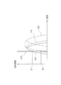
- a region denoted by reference numeral 100 indicates the FBG reflection spectrum when the measurement target part to be temperature-measured is at a given temperature.
- An area denoted by reference numeral 200 indicates a spectrum of incident light emitted by the laser, and its bandwidth is generally narrower than the bandwidth of the FBG reflection spectrum.
- the FBG reflects the incident light indicated by reference numeral 200 at the reflection intensity S1.
- the reflection spectrum of the FBG shifts to the longer wavelength side as indicated by the dashed-dotted region 110, and the reflection intensity of the reflected light changes from S1 to S2.
- the temperature of the part to be measured is obtained based on the difference between the reflection intensities S1 and S2.
- the FBGs are generally formed so that their grating periods are different from each other, that is, the reflection bands of the FBGs are different from each other.
- the bandwidth of the incident light emitted by the laser is narrow, and it is impossible to emit incident light corresponding to the reflection band of each FBG with a single laser.
- a plurality of lasers or wavelength tunable lasers are used as the light source.
- a laser is an expensive device compared with an LED or the like, and a wavelength variable laser is more expensive. Therefore, when performing multipoint temperature measurement using a laser as a light source as in the temperature measurement system described in Patent Document 1, the temperature is The problem is that the cost of the measurement system is high.
- the thermal expansion amount of the FBG when the temperature rises also increases, so that the reflection spectrum of the FBG may shift to a region 120 indicated by a two-dot chain line in FIG. .
- the spectrum 200 of the incident light emitted from the laser is not included in the band of the reflection spectrum, and the reflection on the FBG does not occur, so that it becomes impossible to measure the temperature.
- a temperature measurement system that performs multipoint temperature measurement using a laser as a light source and a temperature measurement system that performs temperature measurement of a measured part having a large temperature change range using a laser as a light source are difficult to construct at low cost. It had the problem of being.
- the present invention has been made to solve such problems, and an object of the present invention is to provide a temperature measurement system that realizes multi-point temperature measurement and wide-range temperature measurement at low cost.
- the temperature measurement system includes an optical fiber having an FBG that changes the wavelength of reflected light with respect to incident light and the wavelength of transmitted light with respect to incident light in accordance with the temperature of the measured part, and the incident light is incident on the optical fiber. And a measuring means for measuring the temperature of the part to be measured based on the reflected light or transmitted light.
- the light source has a bandwidth wider than the bandwidth of the reflection spectrum of the FBG and has a continuous spectrum.
- the light is incident on the optical fiber as incident light, and the measuring unit measures the temperature of the part to be measured based on the amount of change in the position of the reflection spectrum of the FBG or the amount of change in the position of the transmission spectrum of the FBG.
- the temperature measurement system according to the present invention can be used as a vehicle sensor for measuring the temperature of a vehicle.
- the vehicle has a plurality of measured parts, and the optical fiber is provided in the measured parts.
- the present invention also relates to a temperature measurement method for measuring the temperature of a part to be measured using a temperature measurement system.
- the temperature measurement system includes an optical fiber having an FBG that changes a wavelength of reflected light with respect to incident light and a wavelength of transmitted light with respect to incident light in accordance with the temperature of a measurement target part, a light source that makes incident light incident on the optical fiber, Measuring means for measuring the temperature of the part to be measured based on reflected light or transmitted light, and the temperature measuring method includes a step of providing the FBG in the part to be measured, and a bandwidth wider than the bandwidth of the reflection spectrum of the FBG by the light source.
- multipoint temperature measurement and wide-range temperature measurement can be performed at low cost.
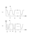
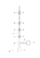
- FIG. 3 is a schematic diagram showing a configuration of an FBG in the temperature measurement system according to the first embodiment. 3 is a graph showing a reflection spectrum of each FBG in the temperature measurement system according to the first embodiment. It is a graph which shows the transmission spectrum input into a measurement means in the temperature measurement system which concerns on Embodiment 1, (a) shows a steady state spectrum, (b) shows the state which the temperature change produced. It is the schematic which shows the structure of the temperature measurement system which concerns on Embodiment 2 of this invention. It is the schematic which shows the structure of the vehicle sensor using the temperature measurement system which concerns on Embodiment 3 of this invention. It is a graph for demonstrating the conventional temperature measuring method.
- FIG. 1 schematically shows a configuration of a temperature measurement system 10 according to the first embodiment.
- the temperature measurement system 10 includes a single optical fiber 11, a light source 12 connected to one end of the optical fiber 11, and measurement means 13 connected to the other end of the optical fiber 11. Further, n FBGs (fiber Bragg gratings) 21, 22, 23,..., 2n are formed in the middle of the optical fiber 11, and these FBGs are subjected to n measurement targets for temperature measurement. It is provided in each of the measurement units 31, 32, 33, ..., 3n. As will be described later, the temperature of each measured part can be measured by the corresponding FBG. That is, the temperature measurement system 10 performs multi-point temperature measurement for measuring the temperatures of a plurality of measured parts using a single optical fiber 11.
- FBGs fiber Bragg gratings
- the optical fiber 11 includes a core 11a through which incident light L1 input from a light source 12 (see FIG. 1) propagates, and a clad 11b that covers the outer periphery of the core 11a.
- the FBG 21 is a diffraction grating in which the refractive index of the core 11a is changed by a predetermined length period (grating period) ⁇ 1 along the axial direction, and emits light of a specific wavelength (Bragg wavelength) with respect to the incident light L1.
- the reflected light L2 is reflected and the remaining light is transmitted as transmitted light L3.
- the optical fiber 11 is made of a material such as quartz glass, for example, and has a positive coefficient of thermal expansion.
- the formation of each FBG is performed by irradiating the core 11a of the optical fiber 11 with ultraviolet rays or the like.
- the grating period ⁇ 1 is one of the elements that define the Bragg wavelength of the FBG 21, and the Bragg wavelength changes linearly with respect to the amount of change of the grating period ⁇ 1. That is, when the temperature of the part to be measured 31 rises and the FBG 21 expands, the grating period ⁇ 1 also increases, and accordingly, the Bragg wavelength shifts to the long wavelength side. On the contrary, when the temperature of the measured part 31 decreases and the FBG 21 contracts, the grating period ⁇ 1 also decreases, and accordingly, the Bragg wavelength shifts to the short wavelength side. Therefore, it becomes possible to measure the temperature of the part to be measured 31 based on the shift amount of the Bragg wavelength.
- the transmitted light L3 transmitted through the FBG 21 is obtained by removing the reflected light L2 from the incident light L1, the shift amount of the Bragg wavelength can be obtained from both the reflection side and the transmission side.
- FBGs 22, 23,..., 2n are arranged downstream of the FBG 21 in the direction in which the incident light L1 propagates (see FIG. 1).
- the transmitted light transmitted through is sequentially incident on the downstream FBG.
- These FBGs have the same configuration as the FBG 21 and are used to measure the temperatures of the corresponding measured parts 32, 33,..., 3n, respectively, but have different grating periods ⁇ 2, ⁇ 3,. .., ⁇ n, that is, each FBG is formed so as to reflect light having different Bragg wavelengths.
- the FBGs 21, 22,..., 2n reflect the reflected light of the reflection spectra 41, 42,.
- the grating period of each FBG is selected so that the corresponding reflection spectrum is located in a wavelength band that is separated from each other, so that it is possible to determine which FBG the reflected light and transmitted light are from.
- the light source 12 is a device that emits broadband light including the reflection spectra 41, 42,..., 4n (see FIG. 3) of the FBGs 21, 22,.
- an LED that emits white light is used.
- the white light emitted by the LED means light having a spectrum in which ultraviolet light (invisible), light having a wavelength corresponding to purple to red (visible), and infrared light (invisible) are continuously connected. That is, the light emitted from the light source 12 as the incident light L1 (see FIG. 2) to the optical fiber 11 is not limited to colorless light, and may include various colors of light according to the spectrum bandwidth. .
- the measuring means 13 is a device that measures the intensity of light within a predetermined band using a compound eye optical element MOS or CCD, and can measure the emission band of the incident light L1 emitted from the light source 12. Yes.
- the temperature measuring system 10 measures the temperature of each measured part based on the transmitted light transmitted by each FBG. It is.
- FBGs 21, 22, 23,..., 2n are provided to the corresponding measured parts 31, 32, 33,.
- Incident light L 1 is incident on the fiber 11.
- the FBG 21 located on the most upstream side reflects the reflected light L2 (see FIG. 2) corresponding to the Bragg wavelength, and the remaining light is downstream as the transmitted light L3 (see FIG. 2). Permeate to the side.
- the FBGs 22, 23,..., 2n reflect the reflected light corresponding to the Bragg wavelength with respect to the transmitted light from the upstream FBG, and transmit the remaining light. Finally, the light transmitted through all the FBGs is input to the measuring means 13 and monitored.
- the transmitted light transmitted by each FBG is obtained by removing the reflected light from the light incident from the upstream side.
- the light source 12 emits broadband light including the reflection spectrum of each FBG in the bandwidth
- the measuring means 13 can measure the emission band of the light emitted from the light source 12. That is, as shown in FIG. 4A, the transmission spectrum 50 that passes through all the FBGs and is input to the measuring means 13 includes the spectra 51, 52,..., 5n reflected by each FBG.
- the measurement means 13 can recognize these spectra as waveforms. Since the reflection spectra 51, 52,..., 5n are separated from each other in the transmission spectrum 50, the corresponding FBGs are determined based on the wavelength band in which they are located.
- FIG. 4A shows a steady state before a temperature change occurs in each measured part.
- the transmission spectrum 50 input to the measuring means 13 moves to the position where the reflection spectrum 51 corresponding to the measured part 31 is indicated by reference numeral 51 ′.
- the reflection spectrum 52 corresponding to the part to be measured 32 is moved to the position indicated by reference numeral 52 ′. Since the measurement means 13 can recognize the reflection spectrum in each FBG as a waveform, the temperature change amount of the measured portions 31 and 32 is based on the movement amount of the reflection spectra 51 and 52, specifically, the reflection spectrum 51. , 52 on the basis of the movement amount of the peak position of the waveform, or the movement amount of the waveform at a predetermined intensity.
- the incident light L1 emitted from the light source 12 has a bandwidth wider than the bandwidth of the reflection spectra 51, 52,..., 5n of the FBGs 21, 22, 23,. Since broadband light having a spectrum is used, a plurality of FBGs can be provided in accordance with the spectrum bandwidth of the incident light L1. In addition, since the incident light L1 has a wide band, the measurable temperature range is expanded regardless of whether the FBG is single or plural. In order to measure the transmission spectrum 50 that has passed through the FBGs 21, 22, 23,..., 2n, the measuring means 13 measures the wavelength band corresponding to the bandwidth of the spectrum of the incident light L1.
- the amount of change in temperature can be determined based on the amount of change in the position of these spectra. In other words, even if a single light source 12 is used, the measurable bandwidth is widened. As in the case where a laser having a narrow emission band is used as a light source, a plurality of light sources or a wavelength of incident light is used. Is not required to be variable. In addition, when the incident light L1 has a wide band, for example, an inexpensive device such as an LED can be used as the light source 12. Therefore, the temperature measurement system 10 can perform multi-point temperature measurement and wide-range temperature measurement at low cost.
- the measuring means 13 measured the temperatures of the corresponding measured parts 31, 32, 33,..., 3n based on the transmission spectra 50 that passed through the FBGs 21, 22, 23,.
- the configuration of the temperature measurement system 10 is simplified. Specifically, when the measuring unit 13 is connected to the reflection side, that is, the light source 12 side, a device such as a circulator is generally required to guide the reflected light from each FBG to the measuring unit.
- the light source 12 may be connected to one end side of the optical fiber 11 and the measurement means 13 may be connected to the other end side. do not need.
- Embodiment 2 a temperature measurement system according to Embodiment 2 of the present invention will be described.
- the temperature measurement system according to the second embodiment is connected to the reflection side, whereas the measurement means 13 in the temperature measurement system 10 according to the first embodiment is connected to the transmission side, that is, the opposite side of the light source 12. It is comprised so that.
- the same reference numerals as those shown in FIGS. 1 to 4 are the same or similar components, and thus detailed description thereof will be omitted.
- the temperature measurement system 60 includes an optical fiber 11 and a light source 12 similar to those in the first embodiment.
- a circulator 62 for branching light propagating from the FBG 21 side to the light source 12 side to the optical fiber 61 is connected between the light source 12 and the FBG 21 located on the most upstream side.
- Measuring means 13 is connected to the tip.
- the temperature measurement system 10 monitors the transmission spectrum 50 (see FIG. 4) that has passed through the FBGs 21, 22, 23,..., 2n, and the reflection spectra 51, 52,. The temperature of the part to be measured was measured based on the amount of change in the position of 5n.
- the temperature measurement system 60 monitors the reflection spectra 41, 42,..., 4n shown in FIG.
- Other configurations and temperature measurement methods are the same as those in the first embodiment.
- the measuring means 13 is connected to the reflection side of the FBGs 21, 22, 23,..., 2n, the same effect as in the first embodiment can be obtained. Further, when the measuring means 13 is connected to the reflection side, for example, if the optical fiber 11 is disconnected between the FBG 21 and the FBG 22, the measuring means 13 includes FBGs 22, 23,. Therefore, it is possible to determine whether or not there is a disconnection and to identify the disconnection location.
- the vehicle sensor 70 is formed by sequentially connecting a battery 72 a provided in the front part of the vehicle 71, parts 72 b and 72 c in the room of the vehicle 71, and the like with the optical fiber 11. . That is, the battery 72a and the above-mentioned parts 72b and 72c correspond to the parts to be measured in the first and second embodiments, and FBGs 21 to 23 are provided for these parts.
- a control unit of a vehicle (not shown) is connected to the measuring means 13, and based on the temperature measurement result using the FBGs 21 to 23, the operation of devices such as a warning light indicating the operating status of the battery and an auto air conditioner is performed. Be controlled.
- Other configurations and temperature measurement methods are the same as those in the first embodiment.
- the temperature measurement system according to the present invention can also be applied as the vehicle sensor 70. In this case, if one optical fiber 11 is laid in the vehicle 71, multipoint temperature measurement can be performed, so that temperature management at a plurality of locations can be performed with a simple configuration.
- the temperature measurement system is configured to perform multipoint temperature measurement
- the temperature measurement system is not limited to a plurality of measured parts, and is used to measure the temperature of one measured part. It is also possible to use it.
- the present invention has an effect that a measurable temperature range can be expanded by using a broadband light source and a measuring unit capable of measuring the emission band of the light source. It is common regardless of the number. Therefore, unlike the case where a laser is used as a light source, there is no problem that the emission band of the light source deviates from the reflection spectrum of the FBG and the temperature cannot be measured.
Landscapes
- Physics & Mathematics (AREA)
- General Physics & Mathematics (AREA)
- Measuring Temperature Or Quantity Of Heat (AREA)
- Light Guides In General And Applications Therefor (AREA)
Abstract
多点温度測定及び広範囲の温度測定を低コストで行うことを実現した温度測定システムを提供する。 温度測定システム10は一本の光ファイバ11を備えており、光ファイバ11のFBG21,22,23,・・・,2nが被測定部31,32,33,・・・,3nにそれぞれ設けられている。光ファイバ11の一端に接続された光源12は、各FBGの反射帯域より広帯域であり且つ連続的なスペクトルの光を、入射光として光ファイバ11に入射する。測定手段13は、各FBGを通過した透過スペクトルの帯域幅を含む帯域を測定可能となっており、入力される透過スペクトル中に示される各FBGの反射スペクトルの移動量に基づいて、対応する被測定部の温度が測定される。
Description
この発明は温度測定システム及び温度測定方法に係り、特に、FBGが形成された光ファイバを利用して被測定部の温度を測定するシステム及び方法に関する。
近年、温度を測定するためのセンサとして、FBG(ファイバブラッググレーティング)が形成された光ファイバが利用される。FBGとは、光ファイバのコアの屈折率を軸方向に沿った所定の長さ周期(グレーティング周期)で変化させた回折格子であって、光ファイバへの入射光に対し、グレーティング周期に応じた特定の波長(ブラッグ波長)の光を反射し、残りの光を透過するという特性を有している。温度変化に応じてFBGが熱膨張すると、それに伴ってグレーティング周期が変化する。ブラッグ波長は、グレーティング周期の変化に対して線形に変化するため、ブラッグ波長の変化量に基づいて温度を測定することが可能となる。また、一本の光ファイバに複数のFBGを形成すれば複数箇所の温度を測定する多点温度度測定が可能となる。例えば特許文献1には、光ファイバへの入射光の光源としてレーザを用い、航空機の外板上に設けられた複数のFBGで温度を測定する温度測定システムが開示されている。
ここで、図7を用いて、レーザを光源としてFBGによる温度測定を行う方法について概略的に説明する。図7において符号100で示される領域は、温度測定の対象となる被測定部が所与の温度にある場合におけるFBGの反射スペクトルを示している。また、符号200で示される領域は、レーザが発する入射光のスペクトルを示しており、その帯域幅は、FBGの反射スペクトルの帯域幅より狭いことが一般的である。被測定部が上記の所与の温度にある場合、FBGは、符号200で示される入射光を反射強度S1にて反射する。また、被測定部の温度が上昇してFBGが伸張すると、FBGの反射スペクトルは一点鎖線の領域110で示されるように長波長側にシフトし、反射光の反射強度がS1からS2へと変化する。上述したように、FBGのブラッグ波長はグレーティング周期の変化、すなわち被測定部の温度変化に対して線形に変化するため、反射強度S1、S2の差異に基づいて被測定部の温度が求められる。
一本の光ファイバに複数のFBGを形成して多点温度測定を行う場合、反射光がどのFBGからのものであるかを判別することが必要となる。したがって、各FBGは、それらのグレーティング周期が互いに異なるように、すなわち各FBGの反射帯域が互いに異なるように形成されることが一般的である。ここで、上述したようにレーザが発する入射光の帯域幅は狭く、単一のレーザで各FBGの反射帯域に対応した入射光を発することはできないため、特許文献1に記載の温度測定システムでは、複数のレーザまたは波長可変レーザを光源として用いている。しかしながら、レーザはLED等と比較すると高価な機器であり、波長可変レーザはさらに高価であるため、特許文献1に記載の温度測定システムのようにレーザを光源として多点温度測定を行う場合、温度測定システムのコストが高くなるという問題点が生じる。
また、被測定部の温度の変化幅が広い場合、温度上昇時におけるFBGの熱膨張量も大きくなるため、FBGの反射スペクトルが図7の二点鎖線で示される領域120にシフトすることがある。このような場合、レーザが発する入射光のスペクトル200は反射スペクトルの帯域内に含まれず、FBGにおける反射が起こらないため、温度の測定を行うことが不可能になるという問題点が生じる。この問題点を回避するには、波長可変レーザを用いるか、または光ファイバの材料を変更してFBGの熱膨張量を少なくすることが必要となるため、多点温度測定を行う場合と同様に、温度測定システムのコストが高くなる。すなわち、レーザを光源として多点温度測定を行う温度測定システム、及びレーザを光源として温度の変化幅が大きい被測定部の温度測定を行う温度測定システムは、システムを低コストで構築することが困難であるという問題点を有していた。
この発明は、このような問題点を解決するためになされたもので、多点温度測定及び広範囲の温度測定を低コストで行うことを実現した温度測定システムを提供することを目的とする。
この発明に係る温度測定システムは、被測定部の温度に応じて入射光に対する反射光の波長と入射光に対する透過光の波長とを変化させるFBGを有する光ファイバと、光ファイバに入射光を入射する光源と、反射光または透過光に基づいて、被測定部の温度を測定する測定手段とを備え、光源は、FBGの反射スペクトルの帯域幅より広い帯域幅を有するとともに連続的なスペクトルを有する光を入射光として光ファイバに入射し、測定手段は、FBGの反射スペクトルの位置の変化量またはFBGの透過スペクトルの位置の変化量に基づいて、被測定部の温度を測定する。
この発明に係る温度測定システムは、車両の温度を測定する車両用センサとして用いることが可能であり、その場合、車両は複数の被測定部を有し、光ファイバは複数の被測定部に設けられる複数のFBGを有する。
また、この発明は、温度測定システムを用いて被測定部の温度を測定する温度測定方法にも関する。温度測定システムは、被測定部の温度に応じて入射光に対する反射光の波長と入射光に対する透過光の波長とを変化させるFBGを有する光ファイバと、光ファイバに入射光を入射する光源と、反射光または透過光に基づいて、被測定部の温度を測定する測定手段とを備え、温度測定方法は、FBGを被測定部に設けるステップと、光源によってFBGの反射スペクトルの帯域幅より広い帯域幅を有するとともに連続的なスペクトルを有する光を入射光として光ファイバに入射するステップと、測定手段によってFBGの反射スペクトルまたはFBGの透過スペクトルを測定し、反射スペクトルの位置の変化量または透過スペクトルの位置の変化量に基づいて、被測定部の温度を算出するステップとを含む。
この発明によれば、温度測定システムにおいて、多点温度測定及び広範囲の温度測定を低コストで行うことが可能となる。
以下に、この発明の実施の形態について添付図に基づいて説明する。
実施の形態1.
図1に、この実施の形態1に係る温度測定システム10の構成を概略的に示す。温度測定システム10は、一本の光ファイバ11と、光ファイバ11の一端に接続された光源12と、光ファイバ11の他端に接続された測定手段13とを備えている。また、光ファイバ11の途中には、n個のFBG(ファイバブラッググレーティング)21,22,23,・・・,2nが形成されており、これらのFBGが温度測定の対象となるn箇所の被測定部31,32,33,・・・,3nにそれぞれ設けられている。後述するように、各被測定部の温度は、対応するFBGによって測定可能となっている。すなわち、温度測定システム10は、複数の被測定部の温度を測定する多点温度測定を一本の光ファイバ11によって行うものである。
実施の形態1.
図1に、この実施の形態1に係る温度測定システム10の構成を概略的に示す。温度測定システム10は、一本の光ファイバ11と、光ファイバ11の一端に接続された光源12と、光ファイバ11の他端に接続された測定手段13とを備えている。また、光ファイバ11の途中には、n個のFBG(ファイバブラッググレーティング)21,22,23,・・・,2nが形成されており、これらのFBGが温度測定の対象となるn箇所の被測定部31,32,33,・・・,3nにそれぞれ設けられている。後述するように、各被測定部の温度は、対応するFBGによって測定可能となっている。すなわち、温度測定システム10は、複数の被測定部の温度を測定する多点温度測定を一本の光ファイバ11によって行うものである。
次に、図2に示されるFBG21を参照して、その構成について説明する。図2に示すように、光ファイバ11は、光源12(図1参照)から入力される入射光L1が伝播するコア11aと、コア11aの外周部を覆うクラッド11bとを有している。FBG21は、コア11aの屈折率を軸方向に沿った所定の長さ周期(グレーティング周期)Λ1で変化させた回折格子であって、入射光L1に対し、特定の波長(ブラッグ波長)の光を反射光L2として反射し、残りの光を透過光L3として透過するという特性を有している。尚、光ファイバ11は、例えば石英ガラス等の材料から形成されており、その熱膨張率は正の値となっている。また、一例として、各FBGの形成は、光ファイバ11のコア11aに紫外線等を照射することによって行われる。
グレーティング周期Λ1は、FBG21のブラッグ波長を規定する要素の1つとなっており、グレーティング周期Λ1の変化量に対してブラッグ波長が線形に変化するようになっている。すなわち、被測定部31の温度が上昇してFBG21が伸張すると、グレーティング周期Λ1も大きくなるため、それに伴ってブラッグ波長が長波長側にシフトする。逆に、被測定部31の温度が低下してFBG21が収縮すると、グレーティング周期Λ1も小さくなるため、それに伴ってブラッグ波長が短波長側にシフトする。したがって、ブラッグ波長のシフト量に基づいて、被測定部31の温度を測定することが可能となる。ここで、FBG21を透過した透過光L3は、入射光L1から反射光L2を除いたものとなるため、ブラッグ波長のシフト量は反射側及び透過側の双方から求めることが可能となっている。
また、図2には示されていないが、入射光L1が伝播する方向におけるFBG21の下流側にはFBG22,23,・・・,2nが配置されており(図1参照)、上流側のFBGが透過した透過光が下流側のFBGに順次入射されるようになっている。これらのFBGは、FBG21と同様の構成を有し、対応する被測定部32,33,・・・,3nの温度をそれぞれ測定するためのものであるが、互いに異なるグレーティング周期Λ2,Λ3,・・・,Λnとなるように、すなわち、各FBGが互いに異なるブラッグ波長の光を反射するように形成されている。図3を用いてより詳細に説明すると、FBG21,22,・・・,2nは、それらのブラッグ波長を中心波長とする反射スペクトル41,42,・・・,4nの反射光をそれぞれ反射する。各FBGのグレーティング周期は、対応する反射スペクトルが互いに離間した波長帯域に位置するように選択され、それにより、反射光及び透過光がどのFBGからのものであるかを判別可能となっている。
図1に戻って、光源12は、各FBG21,22,・・・,2nの反射スペクトル41,42,・・・,4n(図3参照)を帯域幅に含む広帯域の光を発する機器であり、例えば白色光を発するLED等が用いられる。ここで、LEDにより発せられる白色光とは紫外線(不可視)、紫色~赤色に対応する波長の光(可視)および赤外線(不可視)が、連続的につながったスペクトルを示す光を指す。すなわち、光源12が光ファイバ11への入射光L1(図2参照)として発する光は無色の光のみに限定されるものではなく、そのスペクトルの帯域幅に応じた様々な色の光を含み得る。一方、測定手段13は、複眼の光学素子であるMOSやCCDを用いて所定の帯域内における光の強度を測定する機器であり、光源12が発する入射光L1の発光帯域を測定可能となっている。尚、光源12の反対側に測定手段13が接続されていることから明らかであるように、温度測定システム10は、各FBGが透過した透過光に基づいて各被測定部の温度を測定するものである。
次に、この発明の実施の形態1に係る温度測定システムを用いて被測定部31,32,33,・・・,3nの温度を測定する方法について説明する。
図1に示すように、まず、FBG21,22,23,・・・,2nが対応する被測定部31,32,33,・・・,3nに接着等によって設けられ、次いで、光源12から光ファイバ11に入射光L1が入射される。入射光L1が入射されると、最も上流側に位置するFBG21は、そのブラッグ波長に応じた反射光L2(図2参照)を反射し、残りの光を透過光L3(図2参照)として下流側に透過する。同様に、FBG22,23,・・・,2nは、上流側のFBGからの透過光に対してブラッグ波長に応じた反射光を反射し、残りの光を透過する。最終的に、全てのFBGを透過した光が測定手段13に入力されて監視される。
図1に示すように、まず、FBG21,22,23,・・・,2nが対応する被測定部31,32,33,・・・,3nに接着等によって設けられ、次いで、光源12から光ファイバ11に入射光L1が入射される。入射光L1が入射されると、最も上流側に位置するFBG21は、そのブラッグ波長に応じた反射光L2(図2参照)を反射し、残りの光を透過光L3(図2参照)として下流側に透過する。同様に、FBG22,23,・・・,2nは、上流側のFBGからの透過光に対してブラッグ波長に応じた反射光を反射し、残りの光を透過する。最終的に、全てのFBGを透過した光が測定手段13に入力されて監視される。
ここで、各FBGが透過する透過光は、その上流側から入射される光から反射光を除いたものとなる。また、光源12は各FBGの反射スペクトルを帯域幅に含む広帯域の光を発しており、測定手段13は、光源12が発する光の発光帯域を測定可能となっている。すなわち、図4(a)に示されるように、全てのFBGを通過して測定手段13に入力される透過スペクトル50には、各FBGによって反射されたスペクトル51,52,・・・,5nが含まれた状態となっており、測定手段13は、これらのスペクトルを波形として認識することが可能となっている。尚、各反射スペクトル51,52,・・・,5nは透過スペクトル50内において互いに離間しているため、これらが位置する波長帯域に基づいて、対応するFBGが判別される。また、図4(a)は、各被測定部に温度変化が生じる前の定常状態を示すものである。
以上のように透過スペクトル50を監視する温度測定システム10において、被測定部31の温度が低下し、且つ被測定部32の温度が上昇した場合について以下に説明する。図4(a)に示される定常状態から被測定部31の温度が低下すると、対応するFBG21が収縮してブラッグ波長が短波長側にシフトする。また、被測定部32の温度が上昇すると、対応するFBG22が伸張してブラッグ波長が長波長側にシフトする。したがって、図4(b)に示されるように、測定手段13(図1参照)に入力される透過スペクトル50は、被測定部31に対応する反射スペクトル51が符号51’で示される位置に移動し、被測定部32に対応する反射スペクトル52が符号52’で示される位置に移動した状態となる。測定手段13は、各FBGにおける反射スペクトルを波形として認識可能であるため、被測定部31、32の温度変化量が反射スペクトル51、52の移動量に基づいて、具体的には、反射スペクトル51、52を示す波形のピーク位置の移動量や、あるいは所定の強度における波形の移動量等に基づいて測定される。
上述したように、光源12が発する入射光L1を、FBG21,22,23,・・・,2nの反射スペクトル51,52,・・・,5nの帯域幅より広い帯域幅を有するとともに連続的なスペクトルを有する広帯域の光としたので、入射光L1のスペクトルの帯域幅に合わせてFBGを複数とすることが可能となる。また、入射光L1が広帯域であるため、FBGが単一であるか複数であるかにかかわらず、測定可能な温度範囲も広げられた状態となる。測定手段13は、FBG21,22,23,・・・,2nを通過した透過スペクトル50を測定するため、入射光L1のスペクトルの帯域幅に対応した波長帯域を測定すると、その帯域内に各FBGの反射スペクトル51,52,・・・,5nを見つけることができ、これらのスペクトルの位置の変化量に基づいて温度の変化量を求めることができる。すなわち、単体の光源12を用いても測定可能な帯域幅が広がった状態となっており、発光帯域が狭いレーザを光源とする場合のように、光源を複数とすることや、入射光の波長を可変とすることを必要としない。また、入射光L1を広帯域とする場合、例えばLED等の安価な機器を光源12として用いることができる。したがって、温度測定システム10において、多点温度測定及び広範囲の温度測定を低コストで行うことが可能となる。
また、測定手段13によって各FBG21,22,23,・・・,2nを通過した透過スペクトル50に基づいて、対応する被測定部31,32,33,・・・,3nの温度を測定したので、温度測定システム10の構成が簡単になる。具体的には、測定手段13を反射側、すなわち光源12側に接続する場合、各FBGからの反射光を測定手段に導くためにサーキュレータ等の機器を必要とすることが一般的である。一方、温度測定システム10のように透過スペクトル50に基づいて温度測定を行う場合、光ファイバ11の一端側に光源12を接続し、他端側に測定手段13を接続すればよく、サーキュレータ等を必要としない。
実施の形態2.
次に、この発明の実施の形態2に係る温度測定システムについて説明する。この実施の形態2に係る温度測定システムは、実施の形態1に係る温度測定システム10における測定手段13が透過側、すなわち光源12の反対側に接続されていたのに対し、反射側に接続されるように構成したものである。尚、以下に説明する実施の形態において、図1~4に示される符号と同一の符号は同一または同様な構成要素であるので、その詳細な説明は省略する。
次に、この発明の実施の形態2に係る温度測定システムについて説明する。この実施の形態2に係る温度測定システムは、実施の形態1に係る温度測定システム10における測定手段13が透過側、すなわち光源12の反対側に接続されていたのに対し、反射側に接続されるように構成したものである。尚、以下に説明する実施の形態において、図1~4に示される符号と同一の符号は同一または同様な構成要素であるので、その詳細な説明は省略する。
図5に示すように、温度測定システム60は、実施の形態1と同様の光ファイバ11と光源12とを備えている。また、光源12と、最も上流側に位置するFBG21との間には、FBG21側から光源12側に伝播する光を光ファイバ61に分岐するためのサーキュレータ62が接続されており、光ファイバ61の先端に測定手段13が接続されている。実施の形態1における温度測定システム10が、FBG21,22,23,・・・,2nを通過した透過スペクトル50(図4参照)を監視し、それに含まれる反射スペクトル51,52,・・・,5nの位置の変化量に基づいて被測定部の温度を測定していた。一方、温度測定システム60は、図3に示される反射スペクトル41,42,・・・,4nを監視し、これらの移動量に基づいて温度を測定するものである。その他の構成、及び温度の測定方法については、実施の形態1と同様である。
以上のように、測定手段13をFBG21,22,23,・・・,2nの反射側に接続しても、実施の形態1と同様の効果を得ることができる。また、測定手段13を反射側に接続した場合、例えばFBG21とFBG22との間で光ファイバ11が断線したとすると、測定手段13には、断線箇所以降にあるFBG22,23,・・・,2nからの反射光が届かなくなるため、断線の有無の判別及び断線箇所の特定を行うことが可能となる。
実施の形態3.
次に、この発明の実施の形態3に係る温度測定システムについて、電気自動車やハイブリッドカー等に適用される車両用センサとして適用した場合を例として説明する。
図6に示すように、車両用センサ70は、車両71の前部に設けられたバッテリー72aや車両71の居室内にある部位72b、72c等を光ファイバ11で順次接続したものとなっている。すなわち、バッテリー72aや上記の部位72b、72cは、実施の形態1、2における被測定部に相当しており、これらに対してFBG21~23がそれぞれ設けられている。また、測定手段13には、図示しない車両の制御部が接続されており、FBG21~23を利用した温度測定結果に基づいて、バッテリーの稼働状況を示す警告灯やオートエアコン等の機器の動作が制御される。その他の構成及び温度測定方法については、実施の形態1と同様である。
以上のように、この発明に係る温度測定システムは、車両用センサ70として適用することも可能となっている。この場合、一本の光ファイバ11を車両71内に敷設すれば多点温度測定を行えるため、簡単な構成で複数個所の温度管理を行うことが可能となる。
次に、この発明の実施の形態3に係る温度測定システムについて、電気自動車やハイブリッドカー等に適用される車両用センサとして適用した場合を例として説明する。
図6に示すように、車両用センサ70は、車両71の前部に設けられたバッテリー72aや車両71の居室内にある部位72b、72c等を光ファイバ11で順次接続したものとなっている。すなわち、バッテリー72aや上記の部位72b、72cは、実施の形態1、2における被測定部に相当しており、これらに対してFBG21~23がそれぞれ設けられている。また、測定手段13には、図示しない車両の制御部が接続されており、FBG21~23を利用した温度測定結果に基づいて、バッテリーの稼働状況を示す警告灯やオートエアコン等の機器の動作が制御される。その他の構成及び温度測定方法については、実施の形態1と同様である。
以上のように、この発明に係る温度測定システムは、車両用センサ70として適用することも可能となっている。この場合、一本の光ファイバ11を車両71内に敷設すれば多点温度測定を行えるため、簡単な構成で複数個所の温度管理を行うことが可能となる。
実施の形態1~3に係る温度測定システムは多点温度測定を行うものとして構成されたが、被測定部を複数とすることに限定するものではなく、一箇所の被測定部の温度測定に用いることも可能である。本発明は、広帯域の光源と、光源の発光帯域を測定可能な測定手段とを用いることにより、測定可能な温度範囲を広げることができるという効果を有しており、この効果は被測定部の数に関わらず共通のものである。したがって、レーザを光源とする場合のように、光源の発光帯域がFBGの反射スペクトルから外れて温度の測定が不可能となる問題が生じることがない。
Claims (6)
- 被測定部の温度に応じて入射光に対する反射光の波長と前記入射光に対する透過光の波長とを変化させるFBGを有する光ファイバと、
前記光ファイバに前記入射光を入射する光源と、
前記反射光または前記透過光に基づいて、前記被測定部の温度を測定する測定手段と
を備え、
前記光源は、前記FBGの反射スペクトルの帯域幅より広い帯域幅を有するとともに連続的なスペクトルを有する光を前記入射光として前記光ファイバに入射し、
前記測定手段は、前記FBGの反射スペクトルの位置の変化量または前記FBGの透過スペクトルの位置の変化量に基づいて、前記被測定部の温度を測定する温度測定システム。 - 前記光ファイバは複数の前記FBGを有する請求項1に記載の温度測定システム。
- 前記測定手段は、前記FBGの透過スペクトルの位置の変化量に基づいて、対応する前記被測定部の温度を測定する請求項1または2に記載の温度測定システム。
- 前記測定手段は、前記FBGの反射スペクトルの位置の変化量に基づいて、対応する前記被測定部の温度を測定する請求項1または2に記載の温度測定システム。
- 請求項1~4のいずれか一項に記載の温度測定システムを用いて車両の温度を測定する車両用センサであって、
前記車両は複数の被測定部を有し、
前記光ファイバは前記複数の被測定部に設けられる複数のFBGを有する車両用センサ。 - 温度測定システムを用いて被測定部の温度を測定する温度測定方法であって、
前記温度測定システムは、
前記被測定部の温度に応じて入射光に対する反射光の波長と前記入射光に対する透過光の波長とを変化させるFBGを有する光ファイバと、
前記光ファイバに前記入射光を入射する光源と、
前記反射光または前記透過光に基づいて、前記被測定部の温度を測定する測定手段と
を備え、
前記温度測定方法は、
前記FBGを前記被測定部に設けるステップと、
前記光源によって前記FBGの反射スペクトルの帯域幅より広い帯域幅を有するとともに連続的なスペクトルを有する光を前記入射光として前記光ファイバに入射するステップと、
前記測定手段によって前記FBGの反射スペクトルまたは前記FBGの透過スペクトルを測定し、前記反射スペクトルの位置の変化量または前記透過スペクトルの位置の変化量に基づいて、前記被測定部の温度を算出するステップと
を含む温度測定方法。
Applications Claiming Priority (2)
| Application Number | Priority Date | Filing Date | Title |
|---|---|---|---|
| JP2011091421A JP2012225687A (ja) | 2011-04-15 | 2011-04-15 | 温度測定システム及び温度測定方法 |
| JP2011-091421 | 2011-04-15 |
Publications (1)
| Publication Number | Publication Date |
|---|---|
| WO2012140959A1 true WO2012140959A1 (ja) | 2012-10-18 |
Family
ID=47009141
Family Applications (1)
| Application Number | Title | Priority Date | Filing Date |
|---|---|---|---|
| PCT/JP2012/054651 Ceased WO2012140959A1 (ja) | 2011-04-15 | 2012-02-24 | 温度測定システム及び温度測定方法 |
Country Status (2)
| Country | Link |
|---|---|
| JP (1) | JP2012225687A (ja) |
| WO (1) | WO2012140959A1 (ja) |
Families Citing this family (2)
| Publication number | Priority date | Publication date | Assignee | Title |
|---|---|---|---|---|
| JP2016176858A (ja) * | 2015-03-20 | 2016-10-06 | 住友電気工業株式会社 | 光ファイバ温度測定装置、光ファイバの温度測定方法及び光ファイバの温度測定プログラム |
| JP2019148493A (ja) * | 2018-02-27 | 2019-09-05 | 国立研究開発法人宇宙航空研究開発機構 | 繊維強化プラスチック複合材料モニタリングシステム、繊維強化プラスチック複合材料モニタリング方法及び繊維強化プラスチック複合材料成形品 |
Citations (3)
| Publication number | Priority date | Publication date | Assignee | Title |
|---|---|---|---|---|
| JP2008151574A (ja) * | 2006-12-15 | 2008-07-03 | Hitachi Cable Ltd | 物理量測定システム |
| JP2008224670A (ja) * | 2007-03-14 | 2008-09-25 | General Electric Co <Ge> | 温度検出布 |
| JP2010281760A (ja) * | 2009-06-08 | 2010-12-16 | Aisan Ind Co Ltd | 物理量測定装置 |
-
2011
- 2011-04-15 JP JP2011091421A patent/JP2012225687A/ja active Pending
-
2012
- 2012-02-24 WO PCT/JP2012/054651 patent/WO2012140959A1/ja not_active Ceased
Patent Citations (3)
| Publication number | Priority date | Publication date | Assignee | Title |
|---|---|---|---|---|
| JP2008151574A (ja) * | 2006-12-15 | 2008-07-03 | Hitachi Cable Ltd | 物理量測定システム |
| JP2008224670A (ja) * | 2007-03-14 | 2008-09-25 | General Electric Co <Ge> | 温度検出布 |
| JP2010281760A (ja) * | 2009-06-08 | 2010-12-16 | Aisan Ind Co Ltd | 物理量測定装置 |
Also Published As
| Publication number | Publication date |
|---|---|
| JP2012225687A (ja) | 2012-11-15 |
Similar Documents
| Publication | Publication Date | Title |
|---|---|---|
| JP5684086B2 (ja) | 物理量計測システム | |
| US8620161B2 (en) | Wavelength multiplexing unit and wavelength multiplexing method of wavelength multiplexing optical transmission system | |
| EP2824463A1 (en) | Optical fiber for sensor and power device monitoring system | |
| JP2014182101A (ja) | ひずみ計測方法及びひずみ計測装置 | |
| JP2008151574A (ja) | 物理量測定システム | |
| CN204630604U (zh) | 一种sms型并联多路复用光纤传感器 | |
| EP4012854B1 (en) | Method and device for detecting absolute or relative temperature and/or absolute or relative wavelength | |
| JP2013072701A (ja) | 温度及び歪分布計測システム | |
| CN116698406B (zh) | 用于轴承磨损测量的单模光纤及检测装置 | |
| JP2012225687A (ja) | 温度測定システム及び温度測定方法 | |
| JP2008268542A (ja) | 光波長フィルタモジュール及び光ファイバ式温度測定装置 | |
| JP2013032968A (ja) | 光ファイバ型電圧センサ | |
| CN114303044B (zh) | 用于光学应用的装置 | |
| Viegas et al. | Long-period grating fiber sensor with in situ optical source for remote sensing | |
| JP2013083558A (ja) | Fbgひずみセンサ及びひずみ量計測システム | |
| JP5026988B2 (ja) | 近赤外線材料濃度測定とガラスファイバのファイバブラッググレーティングによる温度プロファイル測定との機械的結合 | |
| JP5207421B1 (ja) | 波長検波型光センサシステム | |
| JP5822789B2 (ja) | 光合分波器 | |
| JP2013032967A (ja) | 光ファイバ型電流センサ | |
| WO2012140960A1 (ja) | センサ用光ファイバ | |
| KR100782879B1 (ko) | 광섬유 브래그 격자 제조 장치 및 그 장치로 제조된 브래그격자를 갖는 광섬유 및 중적외선 광섬유 레이저 | |
| JP2000352547A (ja) | 分岐光線路監視システム及び分岐光線路監視方法 | |
| JP5883730B2 (ja) | 光線路監視装置 | |
| KR20170046097A (ko) | 저 손실 투과형 파장 가변 광필터 | |
| Roy et al. | A New Approach of Designing All-fiber Band Rejection Filter based on Multimode-Single mode-Multimode Fiber Concatenated Structure |
Legal Events
| Date | Code | Title | Description |
|---|---|---|---|
| 121 | Ep: the epo has been informed by wipo that ep was designated in this application |
Ref document number: 12771238 Country of ref document: EP Kind code of ref document: A1 |
|
| NENP | Non-entry into the national phase |
Ref country code: DE |
|
| 122 | Ep: pct application non-entry in european phase |
Ref document number: 12771238 Country of ref document: EP Kind code of ref document: A1 |