WO2012140950A1 - 磁性体シート付きケーブル - Google Patents
磁性体シート付きケーブル Download PDFInfo
- Publication number
- WO2012140950A1 WO2012140950A1 PCT/JP2012/053428 JP2012053428W WO2012140950A1 WO 2012140950 A1 WO2012140950 A1 WO 2012140950A1 JP 2012053428 W JP2012053428 W JP 2012053428W WO 2012140950 A1 WO2012140950 A1 WO 2012140950A1
- Authority
- WO
- WIPO (PCT)
- Prior art keywords
- cable
- core wires
- noise suppression
- noise
- magnetic powder
- Prior art date
- Legal status (The legal status is an assumption and is not a legal conclusion. Google has not performed a legal analysis and makes no representation as to the accuracy of the status listed.)
- Ceased
Links
Images





Classifications
-
- H—ELECTRICITY
- H01—ELECTRIC ELEMENTS
- H01B—CABLES; CONDUCTORS; INSULATORS; SELECTION OF MATERIALS FOR THEIR CONDUCTIVE, INSULATING OR DIELECTRIC PROPERTIES
- H01B7/00—Insulated conductors or cables characterised by their form
- H01B7/08—Flat or ribbon cables
- H01B7/0861—Flat or ribbon cables comprising one or more screens
-
- H—ELECTRICITY
- H01—ELECTRIC ELEMENTS
- H01B—CABLES; CONDUCTORS; INSULATORS; SELECTION OF MATERIALS FOR THEIR CONDUCTIVE, INSULATING OR DIELECTRIC PROPERTIES
- H01B7/00—Insulated conductors or cables characterised by their form
- H01B7/08—Flat or ribbon cables
- H01B7/0823—Parallel wires, incorporated in a flat insulating profile
Definitions
- the present invention relates to a cable used for communication, and more particularly to a cable that is not easily affected by noise even if it is downsized.
- EMC Electro-Magnetic Compatibility
- FIG. 11A is a diagram showing a cross section of the cable C1 described in Patent Document 1 cut along the length direction
- FIG. 11B shows a cross section of the cable C2 described in Patent Document 2.
- FIG. 11C is a diagram showing an appearance of the cable C3 described in Patent Document 3.
- a plurality of magnetic bodies MG are arranged at intervals along a core wire W1 having conductivity and an outer periphery coated with an insulator as shown in FIG. Has a structured.
- the cable C2 described in Patent Document 2 has a structure in which conductive core wires W2 are disposed on both surfaces of a metal foil MS1 whose outer periphery is covered with an insulator I1, as shown in FIG.
- the cable C3 described in Patent Document 3 has a metal foil MS2 between the core wire W3 and the core wire W3 which are arranged in parallel and have conductivity and whose outer periphery is covered with the insulator I2. The structure is sandwiched between.
- JP 2009-224073 A JP-A-6-111634 Japanese Patent Laid-Open No. 5-028840
- the present invention solves the above-described problems, and provides a cable that can obtain a desired noise suppression effect even when it is reduced in size or thickness.
- the cable according to claim 1 is a cable provided with a plurality of core wires that are conductive and arranged in parallel at intervals, and an insulating portion made of an insulator that covers the periphery of these core wires.
- the noise suppressor is disposed between the matching core wires, and the noise suppressor is covered with the insulating portion together with the core wires, and the noise suppressor is formed of a synthetic resin material containing flat magnetic powder.
- the cable according to claim 2, wherein the flat magnetic powder included in the noise suppression body is oriented so as to form a layer in a direction connecting the centers of the two adjacent core wires. It is characterized by.
- the noise suppression body is formed by cutting a magnetic sheet obtained by processing the synthetic resin material containing the flat magnetic powder into a sheet shape, and the flat magnetic The powder is oriented so as to form a layer in the thickness direction of the magnetic sheet.
- the cable according to claim 4 is characterized in that a plurality of the core wires and a plurality of the noise suppression bodies are arranged on the same plane and are formed in a band shape.
- the cable according to claim 5 is characterized in that one surface of the insulating portion and the other surface facing the one surface are covered with the magnetic material sheet.
- the cable according to claim 6 is characterized in that a plurality of the core wires and a plurality of the noise suppression bodies are alternately arranged along the outer periphery of the same cylinder, and are formed in a string shape.
- the cable according to claim 7 is characterized in that an outer periphery of the insulating portion is covered with the magnetic material sheet.
- the noise suppressor is disposed between the core wires, so that noise (electromagnetic wave) that enters from the outside and adversely affects a signal transmitted through the cable 100, or is transmitted from a certain core wire.
- the noise suppressor absorbs noise that has an adverse effect on the signal transmitted through the cable 100 to obtain a noise suppression effect, and the noise suppressor is formed of a synthetic resin material containing flat magnetic powder. Even if it is thinner than a cable using a foil (magnetic material), the same or better noise suppression effect can be obtained, and a small and thin cable having a noise suppression effect can be provided.
- the flat magnetic powder contained in the noise suppression body is oriented so as to form a layer in the direction connecting the centers of the core wires. Therefore, as compared with the case where granular magnetic powder is used, the flat magnetic powder 120a is reliably arranged in the linear direction connecting the centers of the core wires 110, and noise that adversely affects the signal transmitted through the cable is more reliably detected. There is an effect that it can be suppressed.
- the noise suppressing body can be easily formed by cutting the magnetic sheet into strips.
- FIG. 2 is a cross-sectional view showing a structure of a cable 100.
- FIG. 2 is a diagram illustrating a configuration of a noise suppression body 120.
- FIG. It is a SEM photograph for demonstrating the flat magnetic powder 120a. It is a figure which shows an example of the apparatus using a doctor blade method.
- 3 is an SEM photograph showing an example of a cross section of a noise suppression body 120. It is a graph which shows the characteristic of the magnetic loss magnetic loss (micro
- 2 is a cross-sectional view showing a structure of a cable 200.
- FIG. 3 is a cross-sectional view showing a structure of a cable 300.
- FIG. 3 is a schematic diagram illustrating a configuration of a noise suppression body 120.
- FIG. 3 is a cross-sectional view showing a structure of a cable 400.
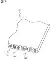
- FIG. 1 is a cross-sectional view showing the structure of the cable 100 of this embodiment.
- FIG. 2 is a schematic diagram showing the configuration of the noise suppression body 120.
- FIG. 3 is an SEM photograph for explaining the flat magnetic powder 120a
- FIG. 3 (a) is an SEM photograph showing an example of the granular magnetic powder
- FIG. 3 (b) is an example of the flat magnetic powder 120a. It is a SEM photograph shown.
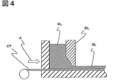
- FIG. 4 is a diagram showing an example of an apparatus using a doctor blade method.
- FIG. 5 is an SEM photograph showing an example of a cross section of the noise suppression body 120.
- FIG. 6 is a graph showing the characteristics of the magnetic susceptibility magnetic loss ⁇ ′′ of the noise suppressor 120 (magnetic sheet 140).
- the cable 100 includes a core wire 110 made of a conductive wire and a flat magnetic powder 120a (see FIG. 3B), and a noise suppression body 120 formed in a strip shape. And an insulating part 130 made of an insulator.
- the plurality of core wires 110 are arranged in parallel on the same plane with a space therebetween, and noise suppression bodies 120 are arranged in parallel with the core wire 110 between the core wires 110 and 110, respectively.
- the periphery of the arranged plurality of core wires 110 and the noise suppression body 120 is covered with an insulating portion 130, and is integrally formed as a belt-like cable 100.
- the core wire 110 is made of a conductive wire.
- the cross-sectional shape is a wire rod, but the cross-sectional shape may be a polygonal shape such as a rectangle or an elliptical shape.
- the insulating part 130 is made of a flexible insulating material.
- the noise suppression body 120 is formed by forming a synthetic resin material 120b containing a flat magnetic powder 120a into a strip shape.
- the synthetic resin material 120b has flexibility.
- the flat magnetic powder 120a is shown as being regularly arranged.
- the flat magnetic powder 120a will be described with reference to FIG. Although the detailed description is omitted, the flat magnetic powder 120a is made by a water atomizing method using a material containing iron as a main component, for example, permalloy (Fe—Ni alloy) as shown in FIG.
- the granular magnetic powder is classified to have a uniform particle size, and is processed into a flat magnetic powder as shown in FIG. 3B using an apparatus such as a planetary stirring ball mill.
- an annealing treatment may be performed to relieve the internal stress as necessary.
- the magnetic sheet 140 containing the flat magnetic powder 120a and formed into a sheet shape is created, and the magnetic sheet 140 is cut into a strip shape.
- the magnetic sheet 140 is made as follows.
- the mixed liquid SL containing the flat magnetic powder 120a and the synthetic resin material 120b constituting the noise suppression body 120 and having viscosity is converted into a base material CT using an apparatus using a doctor blade method as shown in FIG. Is applied in a predetermined thickness on the base material CT by the blade BL while pulling in the direction of arrow A.
- the mixed liquid SL applied to the base CT with a predetermined thickness is heated and dried to thereby form a magnetic body composed of the flat magnetic powder 120a and the synthetic resin material 120b on the base CT.
- a sheet 140 is obtained.
- the flat magnetic powder 120a contained in the magnetic sheet 140 thus manufactured is oriented so as to form a layer in the thickness direction of the magnetic sheet 140, as shown in FIG.
- the flat magnetic powder 120a contained in the noise suppression body 120 made by cutting the body sheet 140 is similarly oriented.
- the flat magnetic powder 120a When the flat flat magnetic powder 120a is oriented as shown in FIG. 5, the flat magnetic powder 120a is more reliably arranged without a gap when the magnetic sheet 140 is viewed from the surface direction.
- the flat magnetic powder 120a is layered in the direction connecting the centers of the two core wires 110 adjacent to the noise suppression body 120. It arrange
- the magnetic loss magnetic loss ⁇ ′′ of the noise suppression body 120 has a characteristic that the fluctuation is small at 15 or more in the frequency band range of 20 Mhz to 1 Ghz. Yes.
- the cable 100 includes a plurality of core wires 110 that are electrically conductive and arranged in parallel at intervals, and an insulating portion 130 made of an insulator that covers the periphery of the core wires 110. It has the noise suppression body 120 which is arrange
- noise suppression body 120 between the core wire 110 and the core wire 110, noise (electromagnetic wave) that enters from the outside and adversely affects a signal transmitted through the cable 100, or a cable transmitted from a certain core wire 110 is transmitted.
- the noise suppressor 120 absorbs noise that adversely affects a signal transmitted through 100 and a noise suppression effect can be obtained, and the noise suppressor 120 is formed of the synthetic resin material 120b containing the flat magnetic powder 120a. Even if it is thinner than a cable using a metal foil (magnetic material), the same or better noise suppression effect can be obtained, and a small and thin cable having a noise suppression effect can be provided.
- the flat magnetic powder 120a included in the noise suppression body 120 is oriented so as to form a layer in the direction connecting the centers of the two core wires 110 adjacent to each other. is doing.
- the flat magnetic powder 120a included in the noise suppressing body 120 is oriented so as to form a layer in the direction connecting the centers of the core wires 110. Therefore, as compared with the case where granular magnetic powder is used, the flat magnetic powder 120a is reliably arranged in the linear direction connecting the centers of the core wires 110, and noise that adversely affects the signal transmitted through the cable is more reliably detected. There is an effect that it can be suppressed.
- the noise suppression body 120 is formed by cutting the magnetic sheet 140 obtained by processing the synthetic resin material 120b containing the flat magnetic powder 120a into a sheet shape into a flat shape, and is flattened.
- the magnetic powder 120a is oriented so as to form a layer in the thickness direction of the magnetic sheet 140.
- the noise suppressing body 120 can be easily formed by cutting the magnetic sheet 140 into a strip shape.
- the plurality of core wires 110 and the plurality of noise suppression bodies 120 are arranged on the same plane and formed in a strip shape.
- This provides an effect of providing a cable having a noise suppression effect and formed in a strip shape.
- the magnetic susceptibility magnetic loss ⁇ ′′ of the noise suppression body 120 has a characteristic of 15 or more in the frequency band range of 20 Mhz to 1 Ghz. .
- the magnetic material sheet 140 is produced with the apparatus using a doctor blade method. Thereby, the magnetic material sheet 140 of uniform thickness can be created with simple equipment.
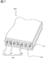
- FIG. 7 is a cross-sectional view showing the structure of the cable 200 of this embodiment.
- the cable 200 according to the present embodiment is obtained by covering one surface of the cable 100 according to the first embodiment and the other surface facing the one surface with a magnetic sheet 140.
- one surface of the cable 100 and the other surface facing the one surface are covered with the magnetic material sheet 140.
- the cable 300 of the third embodiment will be described with reference to FIGS. 8 and 9.
- the common members are the same as those of the first embodiment and the first embodiment. While using the names and symbols used in the second embodiment, the detailed description is omitted.
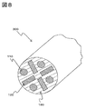
- FIG. 8 is a cross-sectional view showing the structure of the cable 300 of this embodiment.
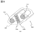
- FIG. 9 is a schematic diagram showing the configuration of the noise suppression body 120.
- the cable 300 includes a core wire 110 made of a conductive wire, a noise suppression body 120 that includes a flat magnetic powder 120 a (see FIG. 9) and is formed in a strip shape, and is insulated. And an insulating part 130 made of a body.
- a plurality of core wires 110 and a plurality of noise suppression bodies 120 are alternately arranged along the outer periphery of the same cylinder, and the periphery of the core wires 110 and the noise suppression bodies 120 are covered with an insulating portion 130 and are string-shaped. Are integrally formed.
- the flat magnetic powder 120a is layered in the direction connecting the centers of the two core wires 110 adjacent to each other. It arrange
- the flat magnetic powder 120a is shown as being regularly arranged.
- the cross-sectional shape of the cable 300 is circular, but a cross-sectional shape such as an ellipse or a polygon may be used.
- the core wire 110 and the noise suppression body 120 are each four, you may change each number as needed.
- a plurality of core wires 110 and a plurality of noise suppression bodies 120 are alternately arranged along the outer periphery of the same cylinder, and are formed in a string shape.
- the cable 300 having a noise suppressing effect and formed in a string shape can be provided.
- the noise suppressing body 120 is arranged so that the flat magnetic powder 120a is oriented so as to form a layer in the direction connecting the centers of the two adjacent core wires 110. Yes.
- the flat magnetic powder 120a included in the noise suppressing body 120 is oriented so as to form a layer in the direction connecting the centers of the core wires 110. Therefore, as compared with the case where granular magnetic powder is used, the flat magnetic powder 120a is reliably arranged in the linear direction connecting the centers of the core wires 110, and noise that adversely affects the signal transmitted through the cable is more reliably detected. There is an effect that it can be suppressed.
- the cable 400 according to the fourth embodiment uses the same members as those of the cable 100 of the first embodiment, the cable 200 of the second embodiment, and the cable 300 of the third embodiment.
- the names and symbols used in the first embodiment, the second embodiment, and the third embodiment are used, and the detailed description is omitted.
- FIG. 10 is a cross-sectional view showing the structure of the cable 400 of this embodiment.
- the cable 400 of the present embodiment is obtained by coating the outer periphery of the cable 300 of the third embodiment with a magnetic sheet 140.
- the outer periphery of the cable 300 of the third embodiment is covered with the magnetic material sheet 140.
- the cable according to the embodiment of the present invention has been specifically described.
- the present invention is not limited to the above-described embodiment, and various modifications can be made without departing from the scope of the invention. Is possible.
- the present invention can be modified as follows, and these embodiments also belong to the technical scope of the present invention.
- the core wire 110 and the noise suppression body 120 are arranged so as not to contact each other in parallel. It may be arranged.
- the noise suppressing body 120 may be additionally provided in the center portion.
- the plurality of core wires 110 and the plurality of noise suppression bodies 120 are alternately arranged along the outer periphery of the same cylinder. Alternatively, they may be arranged alternately along the outer periphery of a tube having a cross-sectional shape such as a polygon. Further, as necessary, the plurality of core wires 110 and the plurality of noise suppression bodies 120 are alternately arranged so as to follow the outer periphery of the conical shape or the polygonal pyramid shape within a range in which the plurality of core wires 110 and the plurality of noise suppression bodies 120 do not contact each other. It may be arranged.
Landscapes
- Insulated Conductors (AREA)
- Communication Cables (AREA)
Abstract
【課題】小型化や薄型化した場合でも所望のノイズ抑制効果が得られるケーブルを提供するものである。 【解決手段】ケーブル100は、導電性を有し互いに間隔をあけて並列に配列された複数本の芯線110と、これらの芯線110の周囲を覆う絶縁体からなる絶縁部130とを備えるケーブルにおいて、隣り合う芯線110間に配置され、芯線110とともに周囲を絶縁部130に覆われたノイズ抑制体120を有し、ノイズ抑制体120は扁平状磁性粉末120aを含有する合成樹脂材で形成されていることを特徴とする。
Description
本発明は、通信に用いるケーブルに関し、特に、小型化してもノイズの影響を受けにくいケーブルに関するものである。
昨今、信号を送信・受信する速度が高速化するに従い、ケーブルから出入りする電磁波にたいするEMC(Electro-Magnetic Compatibility、電磁両立性)や、信号間のクロストークの問題が取り上げられている。
EMCやクロストークの問題を解決する為に、ノイズ抑制効果のある磁性体などが組み込まれたケーブルが求められている。
磁性体などが組み込まれたケーブルとしては、下記の特許文献1ないし特許文献3に記載のケーブルが知られている。
以下、図11を用いて特許文献1ないし特許文献3に記載のケーブルについて概要を説明する。なお、図11(a)は特許文献1に記載のケーブルC1を長さ方向に沿って切断した断面を示す図であり、図11(b)は特許文献2に記載のケーブルC2の断面を示す図であり、図11(c)は特許文献3に記載のケーブルC3の外観を示す図である。
特許文献1に記載のケーブルC1は、図11(a)に示すような、導電性を有し外周を絶縁物で被覆された芯線W1に沿って複数個の磁性体MGが間隔をあけて配置された構造をしている。特許文献2に記載のケーブルC2は、図11(b)に示すような、外周を絶縁物I1で被覆した金属箔MS1の両面に導電性を有する芯線W2を配置した構造をしている。特許文献3に記載のケーブルC3は、図11(c)に示すような、並列に配置され導電性を有し外周を絶縁物I2で被覆された芯線W3と芯線W3との間に金属箔MS2を挟んだ構造をしている。
特許文献1に記載のケーブルC1、特許文献2に記載のケーブルC2または特許文献3に記載のケーブルC3を使用することで、高速通信を行なった場合でもノイズ抑制効果が得られる。
しかしながら、特許文献1ないし特許文献3に記載のケーブルは薄型化や小径化した場合に、所望するノイズ抑制効果が十分に得られなくなるという課題がある。
本発明は、上述した課題を解決して、小型化や薄型化した場合でも所望のノイズ抑制効果が得られるケーブルを提供するものである。
請求項1に記載のケーブルは、導電性を有し互いに間隔をあけて並列に配列された複数本の芯線と、これらの芯線の周囲を覆う絶縁体からなる絶縁部とを備えるケーブルにおいて、隣り合う前記芯線間に配置され、前記芯線とともに周囲を前記絶縁部に覆われたノイズ抑制体を有し、前記ノイズ抑制体は扁平状磁性粉末を含有する合成樹脂材で形成されていることを特徴とする。
請求項2に記載のケーブルは、前記ノイズ抑制体に含まれる前記扁平状磁性粉末は、前記ノイズ抑制体が隣接する2本の前記芯線のそれぞれの中心を結ぶ方向に層を成すように配向していることを特徴とする。
請求項3に記載のケーブルは、前記ノイズ抑制体は、前記扁平状磁性粉末を含有する合成樹脂材をシート状に加工した磁性体シートを短冊状に切断することで形成され、前記扁平状磁性粉末が前記磁性体シートの厚み方向に層を成すように配向されていることを特徴とする。
請求項4に記載のケーブルは、複数の前記芯線と複数の前記ノイズ抑制体を同一平面上に配置し、帯状に形成されたことを特徴とする。
請求項5に記載のケーブルは、前記絶縁部の一面と前記一面に対向する他面とを前記磁性体シートで被覆したことを特徴とする。
請求項6に記載のケーブルは、複数の前記芯線と複数の前記ノイズ抑制体を同一円筒の外周に沿うように交互に配置し、紐状に形成されていることを特徴とする。
請求項7に記載のケーブルは、前記絶縁部の外周を前記磁性体シートで被覆したことを特徴とする。
請求項1の発明によれば、芯線と芯線との間にノイズ抑制体を配置することで、外部から侵入しケーブル100を伝わる信号に対して悪影響を及ぼすノイズ(電磁波)や、ある芯線から発信されケーブル100を伝わる信号に対して悪影響を及ぼすノイズをノイズ抑制体が吸収しノイズ抑制効果を得られ、扁平状磁性粉末を含有する合成樹脂材でノイズ抑制体を形成することで、従来の金属箔(磁性体)を使用したケーブルより薄くしても同等以上のノイズ抑制効果がえられ、ノイズ抑制効果を有した小型・薄型のケーブルを提供することができる、という効果を奏する。
請求項2の発明によれば、ノイズ抑制体に含まれる扁平状磁性粉末は、芯線の中心同士を結ぶ方向に層を成すように配向されている。そのため、粒状の磁性粉末を用いた場合に比較すると、芯線110の中心同士を結ぶ直線方向により確実に扁平状磁性粉末120aが配置され、ケーブルを伝わる信号に対して悪影響を及ぼすノイズをより確実に抑制することができる、という効果を奏する。
請求項3の発明によれば、磁性体シートを短冊状に切断することで、容易にノイズ抑制体を形成することができる、という効果を奏する。
請求項4の発明によれば、ノイズ抑制効果を有し帯状に形成されたケーブルを提供することができる、という効果を奏する。
請求項5の発明によれば、さらに優れたノイズ抑制効果を有する帯状に形成されたケーブルを提供することができる、という効果を奏する。
請求項6の発明によれば、ノイズ抑制効果を有し紐状に形成されたケーブルを提供することができる、という効果を奏する。
請求項7の発明によれば、さらに優れたノイズ抑制効果を有する紐状に形成されたケーブルを提供することができる、という効果を奏する。
[第1実施形態]
以下に、第1実施形態のケーブル100について、図1ないし図6を用いて説明する。図1は本実施形態のケーブル100の構造を示す断面図である。図2はノイズ抑制体120の構成を示す模式図である。図3は扁平状磁性粉末120aを説明するためのSEM写真で、図3(a)は粒状の磁性粉末の一例を示すSEM写真であり、図3(b)は扁平状磁性粉末120aの一例を示すSEM写真である。図4はドクターブレード法を用いた装置の一例を示す図である。図5はノイズ抑制体120の断面の一例を示すSEM写真である。図6はノイズ抑制体120(磁性体シート140)の磁性率磁気損失μ’’の特性を示すグラフである。
以下に、第1実施形態のケーブル100について、図1ないし図6を用いて説明する。図1は本実施形態のケーブル100の構造を示す断面図である。図2はノイズ抑制体120の構成を示す模式図である。図3は扁平状磁性粉末120aを説明するためのSEM写真で、図3(a)は粒状の磁性粉末の一例を示すSEM写真であり、図3(b)は扁平状磁性粉末120aの一例を示すSEM写真である。図4はドクターブレード法を用いた装置の一例を示す図である。図5はノイズ抑制体120の断面の一例を示すSEM写真である。図6はノイズ抑制体120(磁性体シート140)の磁性率磁気損失μ’’の特性を示すグラフである。
まず初めに、本実施形態のケーブル100の構造について説明する。ケーブル100は、図1に示すように、導電性を有した線材からなる芯線110と、扁平状磁性粉末120a(図3(b)を参照)を含有し短冊状に形成されたノイズ抑制体120と、絶縁体からなる絶縁部130と、を備えている。
複数本の芯線110は同一平面上に間隔をあけて並列に配置され、芯線110と芯線110との間にはそれぞれノイズ抑制体120が芯線110と並列に配置されている。
配置された複数の芯線110とノイズ抑制体120との周囲は絶縁部130によって被覆され、帯状のケーブル100として一体に形成される。
次に、構成部品について説明する。
芯線110は、図1に示すように、導電性を有した線材からなる。図1においては断面形状が円形の線材にしているが、断面形状が長方形などの多角形や楕円形状などでも良い。
芯線110は、図1に示すように、導電性を有した線材からなる。図1においては断面形状が円形の線材にしているが、断面形状が長方形などの多角形や楕円形状などでも良い。
絶縁部130は可撓性を有した絶縁物からなる。
ノイズ抑制体120は、図2に示すように、扁平状磁性粉末120aを含有した合成樹脂材120bを短冊状に形成したものである。また、合成樹脂材120bは可撓性を有している。なお、図2においては、説明の都合上、扁平状磁性粉末120aを規則性のある配置がされているように示している。
ノイズ抑制体120は、図2に示すように、扁平状磁性粉末120aを含有した合成樹脂材120bを短冊状に形成したものである。また、合成樹脂材120bは可撓性を有している。なお、図2においては、説明の都合上、扁平状磁性粉末120aを規則性のある配置がされているように示している。
ここで、扁平状磁性粉末120aについて図3を用いて説明する。
詳細の説明は割愛するが、扁平状磁性粉末120aは、図3(a)に示すような、鉄を主成分とする材料、例えばパーマロイ(Fe-Ni合金)を用い、水アトマイズ法により作成された粒状の磁性粉末を分級して粒度を揃え、遊星撹拌型ボールミル等の装置を用いて、図3(b)に示すような、扁平状の磁性粉末に加工したものである。
詳細の説明は割愛するが、扁平状磁性粉末120aは、図3(a)に示すような、鉄を主成分とする材料、例えばパーマロイ(Fe-Ni合金)を用い、水アトマイズ法により作成された粒状の磁性粉末を分級して粒度を揃え、遊星撹拌型ボールミル等の装置を用いて、図3(b)に示すような、扁平状の磁性粉末に加工したものである。
なお、扁平状に加工することで扁平状磁性粉末120aの内部に内部応力を生じることもあるので、必要に応じて、内部応力を緩和させるためにアニール処理を施しても良い。
次に、ノイズ抑制体120の製造方法について簡単に説明する。
ノイズ抑制体120を製造するには、まず初めに、扁平状磁性粉末120aを含有しシート状に形成された磁性体シート140を作成し、磁性体シート140を短冊状に裁断することで形成される。
ノイズ抑制体120を製造するには、まず初めに、扁平状磁性粉末120aを含有しシート状に形成された磁性体シート140を作成し、磁性体シート140を短冊状に裁断することで形成される。
磁性体シート140は次のようにして作られる。
扁平状磁性粉末120aと、ノイズ抑制体120を構成する合成樹脂材120bとを含有し粘性を有した混合液SLを、図4に示すようなドクターブレード法を用いた装置にて、基材CTを矢印A方向に引きながら、ブレードBLにより基材CT上に所定の厚さで塗布する。
扁平状磁性粉末120aと、ノイズ抑制体120を構成する合成樹脂材120bとを含有し粘性を有した混合液SLを、図4に示すようなドクターブレード法を用いた装置にて、基材CTを矢印A方向に引きながら、ブレードBLにより基材CT上に所定の厚さで塗布する。
このようにして基材CT上に所定の厚さで塗布された混合液SLを加熱し乾燥させることにより、基材CT上に扁平状磁性粉末120aと合成樹脂材120bとから構成される磁性体シート140が得られる。
このようにして製造された磁性体シート140内に含有される扁平状磁性粉末120aは、図5に示すように、磁性体シート140の厚さ方向に層を成すように配向しており、磁性体シート140を裁断して作られるノイズ抑制体120に含有される扁平状磁性粉末120aも同様に配向している。
扁平状の扁平状磁性粉末120aが図5に示すように配向することで、磁性体シート140を面方向から見たときに扁平状磁性粉末120aがより確実に隙間なく配置される。
ノイズ抑制体120は、ケーブル100内に配置されたときに、図2に示すように、ノイズ抑制体120が隣接する2本の芯線110のそれぞれの中心を結ぶ方向に扁平状磁性粉末120aが層を成すように配向するように配置される。
また、ノイズ抑制体120(磁性体シート140)の磁性率磁気損失μ’’は、図6に示すように、周波数帯が20Mhzから1Ghzの範囲において、15以上で変動が小さい特性を有している。この磁性率磁気損失μ”は、大きければ大きいほど電磁界エネルギーを熱に変換する効率が高く、ひいては電磁波を吸収する電磁波吸収特性が高くなる。
以下、本実施形態としたことによる効果について説明する。
本実施形態のケーブル100では、導電性を有し互いに間隔をあけて並列に配列された複数本の芯線110と、これらの芯線110の周囲を覆う絶縁体からなる絶縁部130とを備え、隣り合う芯線110と芯線110との間に配置され、芯線110とともに周囲を絶縁部130に覆われたノイズ抑制体120を有し、ノイズ抑制体120は扁平状磁性粉末120aを含有する合成樹脂材120bで形成されている。
本実施形態のケーブル100では、導電性を有し互いに間隔をあけて並列に配列された複数本の芯線110と、これらの芯線110の周囲を覆う絶縁体からなる絶縁部130とを備え、隣り合う芯線110と芯線110との間に配置され、芯線110とともに周囲を絶縁部130に覆われたノイズ抑制体120を有し、ノイズ抑制体120は扁平状磁性粉末120aを含有する合成樹脂材120bで形成されている。
これにより、芯線110と芯線110との間にノイズ抑制体120を配置することで、外部から侵入しケーブル100を伝わる信号に対して悪影響を及ぼすノイズ(電磁波)や、ある芯線110から発信されケーブル100を伝わる信号に対して悪影響を及ぼすノイズをノイズ抑制体120が吸収しノイズ抑制効果を得られ、扁平状磁性粉末120aを含有する合成樹脂材120bでノイズ抑制体120を形成することで、従来の金属箔(磁性体)を使用したケーブルより薄くしても同等以上のノイズ抑制効果が得られ、ノイズ抑制効果を有した小型・薄型のケーブルを提供できる、という効果を奏する。
また、本実施形態のケーブル100では、ノイズ抑制体120に含まれる扁平状磁性粉末120aは、ノイズ抑制体120が隣接する2本の芯線110のそれぞれの中心を結ぶ方向に層を成すように配向している。
これにより、ノイズ抑制体120に含まれる扁平状磁性粉末120aは、芯線110の中心同士を結ぶ方向に層を成すように配向されている。そのため、粒状の磁性粉末を用いた場合に比較すると、芯線110の中心同士を結ぶ直線方向により確実に扁平状磁性粉末120aが配置され、ケーブルを伝わる信号に対して悪影響を及ぼすノイズをより確実に抑制することができる、という効果を奏する。
また、本実施形態のケーブル100では、ノイズ抑制体120は、扁平状磁性粉末120aを含有する合成樹脂材120bをシート状に加工した磁性体シート140を短冊状に切断することで形成され、扁平状磁性粉末120aが磁性体シート140の厚み方向に層を成すように配向されている。
これにより、磁性体シート140を短冊状に切断することで、容易にノイズ抑制体120を形成することができる、という効果を奏する。
また、本実施形態のケーブル100では、複数の芯線110と複数のノイズ抑制体120を同一平面上に配置し、帯状に形成される。
これにより、ノイズ抑制効果を有し帯状に形成されたケーブルを提供できる、という効果を奏する。
また、本実施形態のケーブル100では、ノイズ抑制体120(磁性体シート140)の磁性率磁気損失μ’’は、周波数帯が20Mhzから1Ghzの範囲において、15以上である特性を有している。
これにより、高周波の信号を扱う通信機器や各種電子機器において問題となる高周波側のノイズを安定して遮蔽することができ、高周波の信号を扱う通信機器や各種電子機器のコネクタに好適に用いることができる。
また、本実施形態のケーブル100では、磁性体シート140をドクターブレード法を用いた装置で作成している。
これにより、簡易な設備で均一な厚さの磁性体シート140を作成することができる。
これにより、簡易な設備で均一な厚さの磁性体シート140を作成することができる。
[第2実施形態]
つづいて、以下に、第2実施形態のケーブル200について、図7を用いて説明する。なお、説明するに当たり、本実施形態のケーブル200では第1実施形態のケーブル100と共通の部材を使用しているため、共通の部材に関しては第1実施形態で用いた名称および符号を用いるとともに、詳細の説明は割愛する。
つづいて、以下に、第2実施形態のケーブル200について、図7を用いて説明する。なお、説明するに当たり、本実施形態のケーブル200では第1実施形態のケーブル100と共通の部材を使用しているため、共通の部材に関しては第1実施形態で用いた名称および符号を用いるとともに、詳細の説明は割愛する。
図7は本実施形態のケーブル200の構造を示す断面図である。
本実施形態のケーブル200は、図7に示すように、第1実施形態のケーブル100の一面と一面に対向する他面とを磁性体シート140で被覆したものである。
本実施形態のケーブル200は、図7に示すように、第1実施形態のケーブル100の一面と一面に対向する他面とを磁性体シート140で被覆したものである。
以下、本実施形態としたことによる効果について説明する。
本実施形態のケーブル200では、ケーブル100の一面と一面に対向する他面とを磁性体シート140で被覆している。
本実施形態のケーブル200では、ケーブル100の一面と一面に対向する他面とを磁性体シート140で被覆している。
これにより、ケーブルを伝わる信号に悪影響を及ぼすノイズに対して、さらに優れたノイズ抑制効果を有する帯状に形成されたケーブル200を提供できる。
[第3実施形態]
つづいて、以下に、第3実施形態のケーブル300について、図8および図9を用いて説明する。なお、説明するに当たり、本実施形態のケーブル300では第1実施形態のケーブル100および第2実施形態のケーブル200と共通の部材を使用しているため、共通の部材に関しては第1実施形態および第2実施形態で用いた名称および符号を用いるとともに、詳細の説明は割愛する。
つづいて、以下に、第3実施形態のケーブル300について、図8および図9を用いて説明する。なお、説明するに当たり、本実施形態のケーブル300では第1実施形態のケーブル100および第2実施形態のケーブル200と共通の部材を使用しているため、共通の部材に関しては第1実施形態および第2実施形態で用いた名称および符号を用いるとともに、詳細の説明は割愛する。
図8は本実施形態のケーブル300の構造を示す断面図である。図9はノイズ抑制体120の構成を示す模式図である。
まず初めに、本実施形態のケーブル300の構造について説明する。ケーブル300は、図8に示すように、導電性を有した線材からなる芯線110と、扁平状磁性粉末120a(図9を参照)を含有し短冊状に形成されたノイズ抑制体120と、絶縁体からなる絶縁部130と、を備えている。
ケーブル300は、複数の芯線110と複数のノイズ抑制体120とを同一円筒の外周に沿うように交互に配置し、芯線110とノイズ抑制体120との周囲を絶縁部130で被覆するとともに紐状に一体に形成されている。
ノイズ抑制体120は、ケーブル300内に配置されたときに、図9に示すように、ノイズ抑制体120が隣接する2本の芯線110のそれぞれの中心を結ぶ方向に扁平状磁性粉末120aが層を成すように配向するように配置される。なお、図9においては、説明の都合上、扁平状磁性粉末120aを規則性のある配置がされているように示している。
なお、図8においてはケーブル300の断面形状を円形としたが、楕円形や多角形などの断面形状でも良い。
また、図8においては、芯線110およびノイズ抑制体120はそれぞれ4本だが、必要に応じてそれぞれの本数を変更しても良い。
以下、本実施形態としたことによる効果について説明する。
本実施形態のケーブル300では、複数の芯線110と複数のノイズ抑制体120を同一円筒の外周に沿うように交互に配置し、紐状に形成されている。
これにより、ノイズ抑制効果を有し紐状に形成されたケーブル300を提供できる。
本実施形態のケーブル300では、複数の芯線110と複数のノイズ抑制体120を同一円筒の外周に沿うように交互に配置し、紐状に形成されている。
これにより、ノイズ抑制効果を有し紐状に形成されたケーブル300を提供できる。
また、本実施形態のケーブル300では、ノイズ抑制体120が隣接する2本の芯線110のそれぞれの中心を結ぶ方向に扁平状磁性粉末120aが層を成すように配向するように配置される構造としている。
これにより、ノイズ抑制体120に含まれる扁平状磁性粉末120aは、芯線110の中心同士を結ぶ方向に層を成すように配向されている。そのため、粒状の磁性粉末を用いた場合に比較すると、芯線110の中心同士を結ぶ直線方向により確実に扁平状磁性粉末120aが配置され、ケーブルを伝わる信号に対して悪影響を及ぼすノイズをより確実に抑制することができる、という効果を奏する。
[第4実施形態]
つづいて、以下に、第4実施形態のケーブル400について、図10を用いて説明する。なお、説明するに当たり、本実施形態のケーブル400では第1実施形態のケーブル100、第2実施形態のケーブル200および第3実施形態のケーブル300と共通の部材を使用しているため、共通の部材に関しては第1実施形態、第2実施形態および第3実施形態で用いた名称および符号を用いるとともに、詳細の説明は割愛する。
つづいて、以下に、第4実施形態のケーブル400について、図10を用いて説明する。なお、説明するに当たり、本実施形態のケーブル400では第1実施形態のケーブル100、第2実施形態のケーブル200および第3実施形態のケーブル300と共通の部材を使用しているため、共通の部材に関しては第1実施形態、第2実施形態および第3実施形態で用いた名称および符号を用いるとともに、詳細の説明は割愛する。
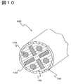
図10は本実施形態のケーブル400の構造を示す断面図である。
本実施形態のケーブル400は、図10に示すように、第3実施形態のケーブル300の外周を磁性体シート140で被覆したものである。
本実施形態のケーブル400は、図10に示すように、第3実施形態のケーブル300の外周を磁性体シート140で被覆したものである。
以下、本実施形態としたことによる効果について説明する。
本実施形態のケーブル400では、第3実施形態のケーブル300の外周を磁性体シート140で被覆している。
本実施形態のケーブル400では、第3実施形態のケーブル300の外周を磁性体シート140で被覆している。
これにより、ケーブルを伝わる信号に悪影響を及ぼすノイズに対して、さらに優れたノイズ抑制効果を有する紐状に形成されたケーブル400を提供することができる。
以上のように、本発明の実施形態に係るケーブルを具体的に説明したが、本発明は上記の実施形態に限定されるものではなく、要旨を逸脱しない範囲で種々変更して実施することが可能である。例えば次のように変形して実施することができ、これらの実施形態も本発明の技術的範囲に属する。
(1)第1実施形態におけるケーブル100および第2実施形態におけるケーブル200において、芯線110およびノイズ抑制体120は並列にそれぞれが接触しないように配置されているが、それぞれが接触しない限り屈曲させて配置しても良い。
(2)第3実施形態におけるケーブル300および第4実施形態におけるケーブル400において、複数の芯線110および複数のノイズ抑制体120が円筒の外周に沿うように配置されたとき、その仮想の円筒の中心部は絶縁部130によって形成されているが、中心部にノイズ抑制体120を追加して配置しても良い。これにより、ケーブル300およびケーブル400を伝わる信号に対して悪影響を及ぼすノイズに対して、さらに優れたノイズ抑制効果を有する紐状に形成されたケーブルを提供できる。
(3)第3実施形態におけるケーブル300および第4実施形態におけるケーブル400において、複数の芯線110と複数のノイズ抑制体120とを同一円筒の外周に沿うように交互に配置しているが、楕円や多角形などの断面形状の筒の外周に沿うように交互に配置しても良い。また、必要に応じて複数の芯線110と複数のノイズ抑制体120とが接触しない範囲で円錐形状や多角錐形状の外周に沿うように複数の芯線110と複数のノイズ抑制体120とを交互に配置しても良い。
100 ケーブル
110 芯線
120 ノイズ抑制体
120a 扁平状磁性粉末
120b 合成樹脂材
130 絶縁部
140 磁性体シート
200 ケーブル
300 ケーブル
400 ケーブル
110 芯線
120 ノイズ抑制体
120a 扁平状磁性粉末
120b 合成樹脂材
130 絶縁部
140 磁性体シート
200 ケーブル
300 ケーブル
400 ケーブル
Claims (7)
- 導電性を有し互いに間隔をあけて並列に配列された複数本の芯線と、これらの芯線の周囲を覆う絶縁体からなる絶縁部とを備えるケーブルにおいて、
隣り合う前記芯線間に配置され、前記芯線とともに周囲を前記絶縁部に覆われたノイズ抑制体を有し、
前記ノイズ抑制体は扁平状磁性粉末を含有する合成樹脂材で形成されていることを特徴とするケーブル。 - 前記ノイズ抑制体に含まれる前記扁平状磁性粉末は、前記ノイズ抑制体が隣接する2本の前記芯線のそれぞれの中心を結ぶ方向に層を成すように配向していることを特徴とする請求項1に記載のケーブル。
- 前記ノイズ抑制体は、前記扁平状磁性粉末を含有する合成樹脂材がシート状に加工された磁性体シートを短冊状に切断することで形成され、前記扁平状磁性粉末が前記磁性体シートの厚み方向に層を成すように配向されていることを特徴とする請求項1に記載のケーブル。
- 複数の前記芯線と複数の前記ノイズ抑制体を同一平面上に配置し、帯状に形成されていることを特徴とする請求項1に記載のケーブル。
- 前記絶縁部の一面と前記一面に対向する他面とを前記磁性体シートで被覆したことを特徴とする請求項4に記載のケーブル。
- 複数の前記芯線と複数の前記ノイズ抑制体を同一円筒の外周に沿うように交互に配置し、紐状に形成されていることを特徴とする請求項1に記載のケーブル。
- 前記絶縁部の外周を前記磁性体シートで被覆したことを特徴とする請求項6に記載のケーブル。
Applications Claiming Priority (2)
| Application Number | Priority Date | Filing Date | Title |
|---|---|---|---|
| JP2011087296A JP2014116071A (ja) | 2011-04-11 | 2011-04-11 | 磁性体シート付きケーブル |
| JP2011-087296 | 2011-04-11 |
Publications (1)
| Publication Number | Publication Date |
|---|---|
| WO2012140950A1 true WO2012140950A1 (ja) | 2012-10-18 |
Family
ID=47009134
Family Applications (1)
| Application Number | Title | Priority Date | Filing Date |
|---|---|---|---|
| PCT/JP2012/053428 Ceased WO2012140950A1 (ja) | 2011-04-11 | 2012-02-14 | 磁性体シート付きケーブル |
Country Status (2)
| Country | Link |
|---|---|
| JP (1) | JP2014116071A (ja) |
| WO (1) | WO2012140950A1 (ja) |
Cited By (1)
| Publication number | Priority date | Publication date | Assignee | Title |
|---|---|---|---|---|
| WO2015124871A1 (fr) * | 2014-02-21 | 2015-08-27 | Labinal Power Systems | Harnais pour la liaison électrique entre plusieurs équipements |
Families Citing this family (1)
| Publication number | Priority date | Publication date | Assignee | Title |
|---|---|---|---|---|
| DE102017116444A1 (de) * | 2017-07-20 | 2018-10-25 | Lisa Dräxlmaier GmbH | Elektrische Flachleiteranordnung für ein Fahrzeug |
Citations (6)
| Publication number | Priority date | Publication date | Assignee | Title |
|---|---|---|---|---|
| JPH06103825A (ja) * | 1992-09-18 | 1994-04-15 | Murata Mfg Co Ltd | フレキシブル配線シート |
| JPH06111635A (ja) * | 1992-09-29 | 1994-04-22 | Murata Mfg Co Ltd | フレキシブル配線シート |
| JPH0831237A (ja) * | 1994-07-21 | 1996-02-02 | Mitsubishi Materials Corp | 電線ケーブル巻装用電磁波シールド材 |
| JPH11111077A (ja) * | 1997-10-01 | 1999-04-23 | Tokin Corp | 通信ケーブル |
| JP2003123554A (ja) * | 2001-10-19 | 2003-04-25 | Oki Electric Cable Co Ltd | 高速・広帯域対型メタリックシールドケ−ブル及びシールドコネクタ |
| JP2011249022A (ja) * | 2010-05-24 | 2011-12-08 | Sumitomo Electric Ind Ltd | 光電気複合ケーブル |
-
2011
- 2011-04-11 JP JP2011087296A patent/JP2014116071A/ja not_active Withdrawn
-
2012
- 2012-02-14 WO PCT/JP2012/053428 patent/WO2012140950A1/ja not_active Ceased
Patent Citations (6)
| Publication number | Priority date | Publication date | Assignee | Title |
|---|---|---|---|---|
| JPH06103825A (ja) * | 1992-09-18 | 1994-04-15 | Murata Mfg Co Ltd | フレキシブル配線シート |
| JPH06111635A (ja) * | 1992-09-29 | 1994-04-22 | Murata Mfg Co Ltd | フレキシブル配線シート |
| JPH0831237A (ja) * | 1994-07-21 | 1996-02-02 | Mitsubishi Materials Corp | 電線ケーブル巻装用電磁波シールド材 |
| JPH11111077A (ja) * | 1997-10-01 | 1999-04-23 | Tokin Corp | 通信ケーブル |
| JP2003123554A (ja) * | 2001-10-19 | 2003-04-25 | Oki Electric Cable Co Ltd | 高速・広帯域対型メタリックシールドケ−ブル及びシールドコネクタ |
| JP2011249022A (ja) * | 2010-05-24 | 2011-12-08 | Sumitomo Electric Ind Ltd | 光電気複合ケーブル |
Cited By (2)
| Publication number | Priority date | Publication date | Assignee | Title |
|---|---|---|---|---|
| WO2015124871A1 (fr) * | 2014-02-21 | 2015-08-27 | Labinal Power Systems | Harnais pour la liaison électrique entre plusieurs équipements |
| FR3017984A1 (fr) * | 2014-02-21 | 2015-08-28 | Labinal | Harnais pour la liaison electrique entre plusieurs equipements |
Also Published As
| Publication number | Publication date |
|---|---|
| JP2014116071A (ja) | 2014-06-26 |
Similar Documents
| Publication | Publication Date | Title |
|---|---|---|
| CN103794296B (zh) | 差动信号传输用电缆以及多芯差动信号传输用电缆 | |
| US9530542B2 (en) | Shielded cable | |
| US9706692B2 (en) | Noise shield cable and method of manufacturing the same | |
| US20160293295A1 (en) | Shielded cable | |
| JP5999062B2 (ja) | 差動信号伝送用ケーブル | |
| US9055667B2 (en) | Noise dampening energy efficient tape and gasket material | |
| JP2015153736A (ja) | ノイズ抑制ケーブル | |
| KR20170114445A (ko) | 케이블용 자기장 차폐 테이프 및 이의 제조 방법 | |
| US20150195961A1 (en) | Shielding braid structure | |
| JP7454929B2 (ja) | 配線回路基板の製造方法 | |
| TW202025179A (zh) | 線材結構及其製造方法 | |
| US10217545B2 (en) | Cable structure | |
| JP2015232984A (ja) | ノイズ抑制ケーブル | |
| WO2012140950A1 (ja) | 磁性体シート付きケーブル | |
| TWM572563U (zh) | 芯線組及使用該芯線組的線纜 | |
| JP2015188146A (ja) | 導波管およびその製造方法 | |
| CN201191533Y (zh) | 机械稳幅稳相测试电缆 | |
| JP2014017084A (ja) | 多芯ケーブル | |
| WO2013161124A1 (ja) | 漏洩同軸ケーブル | |
| TWI476787B (zh) | 共模輻射抑制裝置 | |
| JP2016213112A (ja) | 多心シールドフラットケーブル | |
| CN103065713A (zh) | 核电用高强度全屏蔽抗脉冲超高频电缆 | |
| WO2022209960A1 (ja) | シールド箔および通信用電線 | |
| CN109219335B (zh) | 宽频带吸波片及其制作方法 | |
| CN216250027U (zh) | 传输线 |
Legal Events
| Date | Code | Title | Description |
|---|---|---|---|
| 121 | Ep: the epo has been informed by wipo that ep was designated in this application |
Ref document number: 12771539 Country of ref document: EP Kind code of ref document: A1 |
|
| NENP | Non-entry into the national phase |
Ref country code: DE |
|
| 122 | Ep: pct application non-entry in european phase |
Ref document number: 12771539 Country of ref document: EP Kind code of ref document: A1 |
|
| NENP | Non-entry into the national phase |
Ref country code: JP |