WO2012140917A1 - 画像処理装置および画像処理プログラム - Google Patents
画像処理装置および画像処理プログラム Download PDFInfo
- Publication number
- WO2012140917A1 WO2012140917A1 PCT/JP2012/002600 JP2012002600W WO2012140917A1 WO 2012140917 A1 WO2012140917 A1 WO 2012140917A1 JP 2012002600 W JP2012002600 W JP 2012002600W WO 2012140917 A1 WO2012140917 A1 WO 2012140917A1
- Authority
- WO
- WIPO (PCT)
- Prior art keywords
- image data
- parallax
- image
- pixel
- color
- Prior art date
- Legal status (The legal status is an assumption and is not a legal conclusion. Google has not performed a legal analysis and makes no representation as to the accuracy of the status listed.)
- Ceased
Links
Images






Classifications
-
- H—ELECTRICITY
- H04—ELECTRIC COMMUNICATION TECHNIQUE
- H04N—PICTORIAL COMMUNICATION, e.g. TELEVISION
- H04N13/00—Stereoscopic video systems; Multi-view video systems; Details thereof
- H04N13/20—Image signal generators
- H04N13/204—Image signal generators using stereoscopic image cameras
- H04N13/207—Image signal generators using stereoscopic image cameras using a single two-dimensional [2D] image sensor
- H04N13/211—Image signal generators using stereoscopic image cameras using a single two-dimensional [2D] image sensor using temporal multiplexing
-
- H—ELECTRICITY
- H04—ELECTRIC COMMUNICATION TECHNIQUE
- H04N—PICTORIAL COMMUNICATION, e.g. TELEVISION
- H04N13/00—Stereoscopic video systems; Multi-view video systems; Details thereof
- H04N13/10—Processing, recording or transmission of stereoscopic or multi-view image signals
- H04N13/106—Processing image signals
- H04N13/15—Processing image signals for colour aspects of image signals
-
- H—ELECTRICITY
- H04—ELECTRIC COMMUNICATION TECHNIQUE
- H04N—PICTORIAL COMMUNICATION, e.g. TELEVISION
- H04N13/00—Stereoscopic video systems; Multi-view video systems; Details thereof
- H04N13/10—Processing, recording or transmission of stereoscopic or multi-view image signals
- H04N13/106—Processing image signals
- H04N13/156—Mixing image signals
-
- H—ELECTRICITY
- H04—ELECTRIC COMMUNICATION TECHNIQUE
- H04N—PICTORIAL COMMUNICATION, e.g. TELEVISION
- H04N13/00—Stereoscopic video systems; Multi-view video systems; Details thereof
- H04N13/20—Image signal generators
- H04N13/204—Image signal generators using stereoscopic image cameras
- H04N13/207—Image signal generators using stereoscopic image cameras using a single two-dimensional [2D] image sensor
- H04N13/218—Image signal generators using stereoscopic image cameras using a single two-dimensional [2D] image sensor using spatial multiplexing
-
- H—ELECTRICITY
- H04—ELECTRIC COMMUNICATION TECHNIQUE
- H04N—PICTORIAL COMMUNICATION, e.g. TELEVISION
- H04N13/00—Stereoscopic video systems; Multi-view video systems; Details thereof
- H04N13/20—Image signal generators
- H04N13/257—Colour aspects
-
- H—ELECTRICITY
- H04—ELECTRIC COMMUNICATION TECHNIQUE
- H04N—PICTORIAL COMMUNICATION, e.g. TELEVISION
- H04N23/00—Cameras or camera modules comprising electronic image sensors; Control thereof
- H04N23/60—Control of cameras or camera modules
- H04N23/67—Focus control based on electronic image sensor signals
- H04N23/672—Focus control based on electronic image sensor signals based on the phase difference signals
-
- H—ELECTRICITY
- H04—ELECTRIC COMMUNICATION TECHNIQUE
- H04N—PICTORIAL COMMUNICATION, e.g. TELEVISION
- H04N23/00—Cameras or camera modules comprising electronic image sensors; Control thereof
- H04N23/60—Control of cameras or camera modules
- H04N23/68—Control of cameras or camera modules for stable pick-up of the scene, e.g. compensating for camera body vibrations
- H04N23/682—Vibration or motion blur correction
- H04N23/684—Vibration or motion blur correction performed by controlling the image sensor readout, e.g. by controlling the integration time
- H04N23/6842—Vibration or motion blur correction performed by controlling the image sensor readout, e.g. by controlling the integration time by controlling the scanning position, e.g. windowing
-
- H—ELECTRICITY
- H04—ELECTRIC COMMUNICATION TECHNIQUE
- H04N—PICTORIAL COMMUNICATION, e.g. TELEVISION
- H04N25/00—Circuitry of solid-state image sensors [SSIS]; Control thereof
- H04N25/10—Circuitry of solid-state image sensors [SSIS]; Control thereof for transforming different wavelengths into image signals
- H04N25/11—Arrangement of colour filter arrays [CFA]; Filter mosaics
- H04N25/13—Arrangement of colour filter arrays [CFA]; Filter mosaics characterised by the spectral characteristics of the filter elements
- H04N25/133—Arrangement of colour filter arrays [CFA]; Filter mosaics characterised by the spectral characteristics of the filter elements including elements passing panchromatic light, e.g. filters passing white light
-
- H—ELECTRICITY
- H04—ELECTRIC COMMUNICATION TECHNIQUE
- H04N—PICTORIAL COMMUNICATION, e.g. TELEVISION
- H04N25/00—Circuitry of solid-state image sensors [SSIS]; Control thereof
- H04N25/10—Circuitry of solid-state image sensors [SSIS]; Control thereof for transforming different wavelengths into image signals
- H04N25/11—Arrangement of colour filter arrays [CFA]; Filter mosaics
- H04N25/13—Arrangement of colour filter arrays [CFA]; Filter mosaics characterised by the spectral characteristics of the filter elements
- H04N25/134—Arrangement of colour filter arrays [CFA]; Filter mosaics characterised by the spectral characteristics of the filter elements based on three different wavelength filter elements
-
- H—ELECTRICITY
- H04—ELECTRIC COMMUNICATION TECHNIQUE
- H04N—PICTORIAL COMMUNICATION, e.g. TELEVISION
- H04N25/00—Circuitry of solid-state image sensors [SSIS]; Control thereof
- H04N25/10—Circuitry of solid-state image sensors [SSIS]; Control thereof for transforming different wavelengths into image signals
- H04N25/11—Arrangement of colour filter arrays [CFA]; Filter mosaics
- H04N25/13—Arrangement of colour filter arrays [CFA]; Filter mosaics characterised by the spectral characteristics of the filter elements
- H04N25/135—Arrangement of colour filter arrays [CFA]; Filter mosaics characterised by the spectral characteristics of the filter elements based on four or more different wavelength filter elements
-
- H—ELECTRICITY
- H04—ELECTRIC COMMUNICATION TECHNIQUE
- H04N—PICTORIAL COMMUNICATION, e.g. TELEVISION
- H04N25/00—Circuitry of solid-state image sensors [SSIS]; Control thereof
- H04N25/70—SSIS architectures; Circuits associated therewith
- H04N25/702—SSIS architectures characterised by non-identical, non-equidistant or non-planar pixel layout
-
- H—ELECTRICITY
- H04—ELECTRIC COMMUNICATION TECHNIQUE
- H04N—PICTORIAL COMMUNICATION, e.g. TELEVISION
- H04N25/00—Circuitry of solid-state image sensors [SSIS]; Control thereof
- H04N25/70—SSIS architectures; Circuits associated therewith
- H04N25/703—SSIS architectures incorporating pixels for producing signals other than image signals
- H04N25/704—Pixels specially adapted for focusing, e.g. phase difference pixel sets
-
- H—ELECTRICITY
- H10—SEMICONDUCTOR DEVICES; ELECTRIC SOLID-STATE DEVICES NOT OTHERWISE PROVIDED FOR
- H10F—INORGANIC SEMICONDUCTOR DEVICES SENSITIVE TO INFRARED RADIATION, LIGHT, ELECTROMAGNETIC RADIATION OF SHORTER WAVELENGTH OR CORPUSCULAR RADIATION
- H10F39/00—Integrated devices, or assemblies of multiple devices, comprising at least one element covered by group H10F30/00, e.g. radiation detectors comprising photodiode arrays
- H10F39/80—Constructional details of image sensors
- H10F39/805—Coatings
- H10F39/8053—Colour filters
-
- H—ELECTRICITY
- H10—SEMICONDUCTOR DEVICES; ELECTRIC SOLID-STATE DEVICES NOT OTHERWISE PROVIDED FOR
- H10F—INORGANIC SEMICONDUCTOR DEVICES SENSITIVE TO INFRARED RADIATION, LIGHT, ELECTROMAGNETIC RADIATION OF SHORTER WAVELENGTH OR CORPUSCULAR RADIATION
- H10F39/00—Integrated devices, or assemblies of multiple devices, comprising at least one element covered by group H10F30/00, e.g. radiation detectors comprising photodiode arrays
- H10F39/80—Constructional details of image sensors
- H10F39/806—Optical elements or arrangements associated with the image sensors
- H10F39/8063—Microlenses
-
- H—ELECTRICITY
- H04—ELECTRIC COMMUNICATION TECHNIQUE
- H04N—PICTORIAL COMMUNICATION, e.g. TELEVISION
- H04N23/00—Cameras or camera modules comprising electronic image sensors; Control thereof
- H04N23/80—Camera processing pipelines; Components thereof
- H04N23/84—Camera processing pipelines; Components thereof for processing colour signals
- H04N23/843—Demosaicing, e.g. interpolating colour pixel values
Definitions
- the present invention relates to an image processing apparatus and an image processing program.
- a stereo imaging device that captures a stereo image composed of a right-eye image and a left-eye image using two imaging optical systems is known. Such a stereo imaging device causes parallax to occur in two images obtained by imaging the same subject by arranging two imaging optical systems at regular intervals.
- the image processing apparatus includes reference image data generated by capturing the same scene and parallax image data having parallax with respect to a subject image of the reference image data, and at least one of them Supports image parallax between the same subject image of reference image data and parallax image data, and an image acquisition unit that acquires non-color image data in which at least part of primary color information for generating a color image is missing
- a parallax amount calculation unit that calculates the amount of parallax to be transmitted, and based on the parallax amount, at least a part of primary color information of either one of the reference image data and the parallax pixel data is transplanted to the other to convert the non-color image data into a color image
- an image conversion unit for converting the data for converting the data.
- the image processing program includes at least one of reference image data and parallax image data having a parallax with respect to a subject image of the reference image data generated by capturing the same scene.
- An image acquisition step for acquiring a group of image data that is non-color image data from which at least a part of primary color information for generating a color image is missing, and support for parallax between the same subject image of reference image data and parallax image data
- a parallax amount calculating step for calculating the amount of parallax to be performed, and based on the parallax amount, at least a part of primary color information of either one of the reference image data and the parallax pixel data is transplanted to the other to convert the non-color image data into a color image
- An image conversion step for converting to data is executed by a computer.
- the digital camera according to the present embodiment which is a form of the imaging device, is configured to generate a plurality of viewpoint images for one scene by one shooting. Each image having a different viewpoint is called a parallax image.
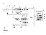
- FIG. 1 is a diagram illustrating a configuration of a digital camera 10 according to an embodiment of the present invention.
- the digital camera 10 includes a photographic lens 20 as a photographic optical system, and guides a subject light beam incident along the optical axis 21 to the image sensor 100.
- the photographing lens 20 may be an interchangeable lens that can be attached to and detached from the digital camera 10.
- the digital camera 10 includes an image sensor 100, a control unit 201, an A / D conversion circuit 202, a memory 203, a drive unit 204, an image processing unit 205, a memory card IF 207, an operation unit 208, a display unit 209, an LCD drive circuit 210, and an AF.
- a sensor 211 is provided.
- the direction parallel to the optical axis 21 toward the image sensor 100 is defined as the z-axis plus direction
- the direction toward the front of the drawing in the plane orthogonal to the z-axis is the x-axis plus direction
- the upward direction on the drawing is y.
- the axis is defined as the plus direction.
- the coordinate axes are displayed so that the orientation of each figure can be understood with reference to the coordinate axes of FIG.
- the photographing lens 20 is composed of a plurality of optical lens groups, and forms an image of a subject light flux from the scene in the vicinity of its focal plane.
- the photographic lens 20 is represented by a single virtual lens arranged in the vicinity of the pupil.
- the image sensor 100 is disposed near the focal plane of the photographic lens 20.
- the image sensor 100 is an image sensor such as a CCD or CMOS sensor in which a plurality of photoelectric conversion elements are two-dimensionally arranged.
- the image sensor 100 is controlled in timing by the drive unit 204, converts the subject image formed on the light receiving surface into an image signal, and outputs the image signal to the A / D conversion circuit 202.
- the A / D conversion circuit 202 converts the image signal output from the image sensor 100 into a digital image signal and outputs the digital image signal to the memory 203.
- the image processing unit 205 performs various image processing using the memory 203 as a work space, and generates image data.
- the image processing unit 205 generates a data data group from a signal output from the image sensor 100 and acquires the data acquisition unit 231.
- a calculation unit 232 and an image conversion unit 233 for converting into color image data are included. Details of each processing will be described later.
- the image processing unit 205 also has general image processing functions such as adjusting image data according to the selected image format.
- the generated image data is converted into a display signal by the LCD drive circuit 210 and displayed on the display unit 209.
- the data is recorded on the memory card 220 attached to the memory card IF 207.
- the AF sensor 211 is a phase difference sensor in which a plurality of distance measuring points are set with respect to the subject space, and detects the defocus amount of the subject image at each distance measuring point.
- a series of shooting sequences is started when the operation unit 208 receives a user operation and outputs an operation signal to the control unit 201.
- Various operations such as AF and AE accompanying the imaging sequence are executed under the control of the control unit 201.
- the control unit 201 analyzes the detection signal of the AF sensor 211 and executes focus control for moving a focus lens that constitutes a part of the photographing lens 20.
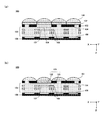
- FIG. 2 is a schematic diagram showing a cross section of the image sensor according to the embodiment of the present invention.
- FIG. 2A is a schematic cross-sectional view of the image sensor 100 in which the color filter 102 and the aperture mask 103 are separately formed.
- FIG. 2B is a schematic cross-sectional view of an image pickup device 120 including a screen filter 121 in which a color filter portion 122 and an opening mask portion 123 are integrally formed as a modification of the image pickup device 100.
- the image sensor 100 is configured by arranging a micro lens 101, a color filter 102, an aperture mask 103, a wiring layer 105, and a photoelectric conversion element 108 in order from the subject side.
- the photoelectric conversion element 108 is configured by a photodiode that converts incident light into an electrical signal.
- a plurality of photoelectric conversion elements 108 are two-dimensionally arranged on the surface of the substrate 109.
- the image signal converted by the photoelectric conversion element 108, the control signal for controlling the photoelectric conversion element 108, and the like are transmitted / received via the wiring 106 provided in the wiring layer 105.
- an opening mask 103 having openings 104 provided in one-to-one correspondence with each photoelectric conversion element 108 is provided in contact with the wiring layer.
- the opening 104 is shifted for each corresponding photoelectric conversion element 108 so that the relative position is precisely determined.
- parallax occurs in the subject light beam received by the photoelectric conversion element 108 by the action of the opening mask 103 including the opening 104.
- the aperture mask 103 does not exist on the photoelectric conversion element 108 that does not generate parallax.
- the aperture mask 103 having the aperture 104 that does not limit the subject luminous flux incident on the corresponding photoelectric conversion element 108, that is, allows the entire effective luminous flux to pass therethrough is provided.
- the aperture 107 formed by the wiring 106 defines the subject luminous flux that is incident, so the wiring 106 is regarded as an aperture mask that allows the entire effective luminous flux that does not cause parallax to pass.
- the opening mask 103 may be arranged separately and independently corresponding to each photoelectric conversion element 108, or may be formed collectively for a plurality of photoelectric conversion elements 108 in the same manner as the manufacturing process of the color filter 102. .
- the color filter 102 is provided on the opening mask 103.
- the color filter 102 is a filter provided in a one-to-one correspondence with each photoelectric conversion element 108, which is colored so as to transmit a specific wavelength band to each photoelectric conversion element 108.
- These color filters can be said to be primary color filters for generating a color image.
- the primary color filter combination is, for example, a red filter that transmits the red wavelength band, a green filter that transmits the green wavelength band, and a blue filter that transmits the blue wavelength band. As will be described later, these color filters are arranged in a lattice pattern corresponding to the photoelectric conversion elements 108.
- the microlens 101 is provided on the color filter 102.
- the microlens 101 is a condensing lens for guiding more incident subject light flux to the photoelectric conversion element 108.
- the microlenses 101 are provided in a one-to-one correspondence with the photoelectric conversion elements 108.
- the optical axis of the microlens 101 is shifted so that more subject light flux is guided to the photoelectric conversion element 108. It is preferable.
- the arrangement position may be adjusted so that more specific subject light beam, which will be described later, is incident along with the position of the opening 104 of the opening mask 103.
- one unit of the aperture mask 103, the color filter 102, and the microlens 101 provided on a one-to-one basis corresponding to each photoelectric conversion element 108 is referred to as a pixel.
- a pixel provided with the opening mask 103 that generates parallax is referred to as a parallax pixel
- a pixel that is not provided with the opening mask 103 that generates parallax is referred to as a non-parallax pixel.
- the effective pixel area of the image sensor 100 is about 24 mm ⁇ 16 mm, the number of pixels reaches about 12 million.
- the microlens 101 may not be provided.
- the wiring layer 105 is provided on the side opposite to the photoelectric conversion element 108.
- the color filter 102 and the opening mask 103 can be integrally formed if the opening 104 of the opening mask 103 has a color component.
- the corresponding color filter 102 may not be provided for the pixel. Or you may arrange
- the screen filter 121 is formed by, for example, blue-green-red coloring in the color filter portion 122 and black in the opening mask portion 123 except for the opening portion 104. Since the image sensor 120 that employs the screen filter 121 has a shorter distance from the microlens 101 to the photoelectric conversion element 108 than the image sensor 100, the light collection efficiency of the subject light flux is high.
- FIG. 3 is a schematic diagram illustrating a state in which a part of the image sensor 100 is enlarged.
- the color arrangement of the color filter 102 is not considered until the reference is resumed later.
- the image sensor is a collection of only parallax pixels having the color filter 102 of the same color (including the case of being transparent). Therefore, the repetitive pattern described below may be considered as an adjacent pixel in the color filter 102 of the same color.
- the opening 104 of the opening mask 103 is provided with a relative shift with respect to each pixel.
- the openings 104 are provided at positions displaced from each other.
- the entire image sensor 100 has a two-dimensional and periodic array of photoelectric conversion element groups each including a set of six parallax pixels each having an aperture mask 103 that gradually shifts from the left side to the right side of the drawing. . That is, it can be said that the image sensor 100 is configured by periodically repeating a repeating pattern 110 including a set of photoelectric conversion element groups.
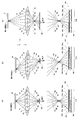
- FIG. 4 is a conceptual diagram illustrating the relationship between the parallax pixels and the subject.
- FIG. 4A shows a photoelectric conversion element group of a repetitive pattern 110t arranged in the center orthogonal to the photographing optical axis 21 in the image pickup element 100
- FIG. 4B shows a repetitive arrangement arranged in the peripheral portion.
- the photoelectric conversion element group of the pattern 110u is typically shown.
- the subject 30 in FIGS. 4A and 4B is in the in-focus position with respect to the photographic lens 20.
- FIG. 4C schematically shows a relationship when the subject 31 existing at the out-of-focus position with respect to the photographing lens 20 is captured corresponding to FIG.
- the subject luminous flux passes through the pupil of the photographic lens 20 and is guided to the image sensor 100.
- Six partial areas Pa to Pf are defined for the entire cross-sectional area through which the subject luminous flux passes. For example, in the pixel at the left end of the sheet of the photoelectric conversion element group constituting the repetitive patterns 110t and 110u, only the subject luminous flux emitted from the partial region Pf reaches the photoelectric conversion element 108 as can be seen from the enlarged view.
- the position of the opening 104f of the opening mask 103 is determined.
- the position of the opening 104e corresponding to the partial area Pe the position of the opening 104d corresponding to the partial area Pd, and the position of the opening 104c corresponding to the partial area Pc.
- the position of the opening 104b is determined corresponding to the partial area Pb
- the position of the opening 104a is determined corresponding to the partial area Pa.
- the position of the opening 104f is determined by the inclination of the principal ray Rf of the subject light beam emitted from the partial region Pf, which is defined by the relative positional relationship between the partial region Pf and the leftmost pixel, for example. You can say. Then, when the photoelectric conversion element 108 receives the subject luminous flux from the subject 30 existing at the in-focus position via the opening 104f, the subject luminous flux is coupled on the photoelectric conversion element 108 as shown by the dotted line. Image.
- the position of the opening 104e is determined by the inclination of the principal ray Re
- the position of the opening 104d is determined by the inclination of the principal ray Rd
- the position of the opening 104c is determined by the inclination of the principal ray Rc.
- the position of the opening 104b is determined by the inclination of the light ray Rb
- the position of the opening 104a is determined by the inclination of the principal ray Ra.
- the light beam emitted from the minute region Ot on the subject 30 that intersects the optical axis 21 among the subject 30 existing at the in-focus position passes through the pupil of the photographing lens 20. Then, each pixel of the photoelectric conversion element group constituting the repetitive pattern 110t is reached. That is, each pixel of the photoelectric conversion element group constituting the repetitive pattern 110t receives the light beam emitted from one minute region Ot through the six partial regions Pa to Pf.
- the minute region Ot has an extent corresponding to the positional deviation of each pixel of the photoelectric conversion element group constituting the repetitive pattern 110t, it can be approximated to substantially the same object point. Similarly, as shown in FIG.
- the light beam emitted from the minute region Ou on the subject 30 that is separated from the optical axis 21 among the subject 30 that exists at the in-focus position passes through the pupil of the photographing lens 20. It passes through and reaches each pixel of the photoelectric conversion element group constituting the repetitive pattern 110u. That is, each pixel of the photoelectric conversion element group constituting the repetitive pattern 110u receives a light beam emitted from one minute region Ou via each of the six partial regions Pa to Pf.
- the micro area Ou has an extent corresponding to the positional deviation of each pixel of the photoelectric conversion element group constituting the repetitive pattern 110u, but substantially the same object point. Can be approximated.
- the minute area captured by the photoelectric conversion element group differs according to the position of the repetitive pattern 110 on the image sensor 100, and each pixel constituting the photoelectric conversion element group Captures the same minute region through different partial regions.
- each repetitive pattern 110 corresponding pixels receive the subject luminous flux from the same partial area. That is, in the figure, for example, the leftmost pixel of each of the repeated patterns 110t and 110u receives the subject light flux from the same partial region Pf.
- each of the parallax pixels arranged on the image sensor 100 includes one of six types of aperture masks.
- the subject luminous flux from the subject 31 present at the out-of-focus position passes through the six partial areas Pa to Pf of the pupil of the photographing lens 20 and reaches the image sensor 100.
- the subject light flux from the subject 31 existing at the out-of-focus position forms an image at another position, not on the photoelectric conversion element 108.
- the subject 31 exists at a position farther from the imaging element 100 than the subject 30, the subject light flux forms an image on the subject 31 side with respect to the photoelectric conversion element 108.
- the subject luminous flux forms an image on the opposite side of the subject 31 from the photoelectric conversion element 108.
- the subject luminous flux radiated from the minute region Ot ′ among the subjects 31 existing at the out-of-focus position depends on which of the six partial regions Pa to Pf, the corresponding pixels in different sets of repetitive patterns 110.
- the subject luminous flux that has passed through the partial region Pd is incident on the photoelectric conversion element 108 having the opening 104d included in the repeated pattern 110t ′ as the principal ray Rd ′.
- the subject light beam that has passed through another partial region does not enter the photoelectric conversion element 108 included in the repetitive pattern 110t ′, and the repetitive pattern in the other repetitive pattern.
- the subject luminous flux reaching each photoelectric conversion element 108 constituting the repetitive pattern 110t ′ is a subject luminous flux radiated from different minute areas of the subject 31. That is, a subject luminous flux having a principal ray as Rd ′ is incident on 108 corresponding to the opening 104d, and the principal rays are incident on Ra + , Rb + , Rc + , Re to the photoelectric conversion elements 108 corresponding to the other openings. +, although subject light flux to Rf + is incident, these object light is a subject light flux emitted from different micro region of the object 31. Such a relationship is the same in the repeated pattern 110u arranged in the peripheral portion in FIG.
- the subject image A captured by the photoelectric conversion element 108 corresponding to the opening 104a and the subject image D captured by the photoelectric conversion element 108 corresponding to the opening 104d are: If the image is for the subject present at the in-focus position, there is no shift, and if the image is for the subject present at the out-of-focus position, there is a shift. Then, the direction and amount of the shift are determined by how much the subject existing at the out-of-focus position is shifted from the focus position and by the distance between the partial area Pa and the partial area Pd. That is, the subject image A and the subject image D are parallax images. Since this relationship is the same for the other openings, six parallax images are formed corresponding to the openings 104a to 104f.
- a parallax image is obtained by gathering together the outputs of pixels corresponding to each other in each of the repetitive patterns 110 configured as described above. That is, the output of the pixel that has received the subject light beam emitted from a specific partial area among the six partial areas Pa to Pf forms a parallax image.
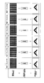
- FIG. 5 is a conceptual diagram illustrating processing for generating a parallax image.
- the figure shows, in order from the left column, the generation of the parallax image data Im_f generated by collecting the outputs of the parallax pixels corresponding to the opening 104f, the generation of the parallax image data Im_e by the output of the opening 104e, the opening State of generation of parallax image data Im_d by output of 104d, state of generation of parallax image data Im_c by output of opening 104c, state of generation of parallax image data Im_b by output of opening 104b, parallax by output of opening 104a
- the parallax image data Im_f is generated by the output of the opening 104f will be described.
- the repetitive pattern 110 composed of a group of photoelectric conversion elements including a set of six parallax pixels is arranged in a horizontal row. Accordingly, the parallax pixels having the opening 104f exist every six pixels in the left-right direction and continuously in the vertical direction on the image sensor 100. Each of these pixels receives the subject luminous flux from different microregions as described above. Therefore, when the outputs of these parallax pixels are collected and arranged, a parallax image is obtained.
- each pixel of the image sensor 100 is a square pixel, simply gathering results in the result that the number of pixels in the horizontal direction is reduced to 1/6, and vertically long image data is generated. End up. Therefore, by performing an interpolation process to obtain the number of pixels 6 times in the horizontal direction, the parallax image data Im_f is generated as an image with an original aspect ratio.
- the parallax image data before the interpolation processing is an image that is thinned by 1/6 in the horizontal direction, the resolution in the horizontal direction is lower than the resolution in the vertical direction. That is, it can be said that the number of generated parallax image data and the improvement in resolution are in a conflicting relationship.
- parallax image data Im_e to parallax image data Im_a are obtained. That is, the digital camera 10 can generate a six-view parallax image having parallax in the horizontal direction.
- FIG. 6 is a diagram illustrating another example of the repeated pattern 110.
- FIG. 6A shows an example in which a vertical pattern of 110 pixels is used as 6 pixels.
- the positions of the respective openings 104 are determined so as to gradually shift from the left side to the right side of the drawing from the parallax pixel at the top of the drawing to the bottom.
- the repeated pattern 110 arranged in this way, it is possible to generate a six-view parallax image that gives parallax in the horizontal direction.
- the repetitive pattern 110 in FIG. 3 it can be said that the repetitive pattern maintains the horizontal resolution instead of sacrificing the vertical resolution.
- FIG. 6B is an example in which six pixels adjacent in an oblique direction are used as a repeated pattern 110.
- the positions of the openings 104 are determined so as to gradually shift from the left side to the right side of the drawing from the parallax pixel at the upper left corner of the drawing toward the lower right.
- the repeated pattern 110 arranged in this way, it is possible to generate a six-view parallax image that gives parallax in the horizontal direction.
- the repetitive pattern 110 increases the number of parallax images while maintaining the vertical resolution and the horizontal resolution to some extent.
- the repeating pattern 110 in FIG. 3 and the repeating pattern 110 in FIGS. 6A and 6B are respectively compared, when generating parallax images with six viewpoints, a single image is output from the whole that is not a parallax image. It can be said that this is the difference between sacrificing the resolution in the vertical direction and the horizontal direction with respect to the resolution in the case.
- the horizontal resolution is set to 1/6.
- the vertical resolution is 1/6.
- 6B has a configuration in which the vertical direction is 1/3 and the horizontal direction is 1/2.
- one opening 104a to 104f is provided corresponding to each pixel in one pattern, and the subject luminous flux is received from one of the corresponding partial areas Pa to Pf. It is configured as follows. Accordingly, the parallax amount is the same for any of the repeated patterns 110.
- FIG. 7 is a diagram illustrating an example of a two-dimensional repetitive pattern 110.
- the repetitive pattern 110 is formed using 36 pixels of 6 pixels in the vertical direction and 6 pixels in the horizontal direction as a set of photoelectric conversion element groups.
- As the position of the opening 104 for each pixel 36 types of opening masks 103 that are shifted in the vertical and horizontal directions are prepared. Specifically, each opening 104 gradually shifts from the upper side to the lower side from the upper end pixel to the lower end pixel of the repetitive pattern 110, and at the same time, gradually from the left end pixel to the right end pixel, from the left side to the right side. Positioned to shift.
- the image sensor 100 having such a repetitive pattern 110 can output a parallax image of 36 viewpoints that gives parallax in the vertical direction and the horizontal direction.
- the pattern 110 is not limited to the example in FIG. 7, and the repetitive pattern 110 can be determined so as to output parallax images with various viewpoints.
- a rectangle is adopted as the shape of the opening 104.
- the amount of light guided to the photoelectric conversion element 108 is ensured by making the width in the vertical direction that is not shifted wider than the width in the horizontal direction that is the shift direction.
- the shape of the opening 104 is not limited to a rectangle.
- FIG. 8 is a diagram for explaining another shape of the opening 104.
- the shape of the opening 104 is circular.
- an unscheduled subject light beam can be prevented from entering the photoelectric conversion element 108 as stray light because of the relative relationship with the microlens 101 having a hemispherical shape.
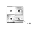
- FIG. 9 is a diagram illustrating the Bayer arrangement.
- the Bayer array is an array in which the green filter is assigned to the upper left and lower right pixels, the red filter is assigned to the lower left pixel, and the blue filter is assigned to the upper right pixel.
- the upper left pixel to which the green filter is assigned is the Gb pixel
- the lower right pixel to which the green filter is assigned is the Gr pixel.
- a pixel to which a red filter is assigned is an R pixel
- a pixel to which blue is assigned is a B pixel.
- a horizontal direction in which Gb pixels and B pixels are arranged is defined as Gb row, and a horizontal direction in which R pixels and Gr pixels are arranged is defined as Gr row.
- a vertical direction in which Gb pixels and R pixels are arranged is a Gb column, and a vertical direction in which B pixels and Gr pixels are arranged is a Gr column.
- a huge number of repetitive patterns 110 can be set for such an array of the color filters 102 depending on what color pixels the parallax pixels and non-parallax pixels are allocated to. If the outputs of pixels without parallax are collected, photographic image data having no parallax can be generated in the same way as normal photographic images. Therefore, if the ratio of pixels without parallax is relatively increased, a 2D image with high resolution can be output. In this case, since the number of parallax pixels is relatively small, the image quality is degraded as a 3D image including a plurality of parallax images. Conversely, if the ratio of the parallax pixels is increased, the image quality is improved as a 3D image, but the non-parallax pixels are relatively reduced, so that a 2D image with low resolution is output.
- FIG. 10 is a diagram illustrating a variation in the case where there are two types of parallax pixels with respect to the allocation of parallax pixels to the Bayer array.
- the parallax pixels are assumed to be a parallax L pixel whose opening 104 is decentered to the left of the center and a parallax R pixel decentered to the right. That is, the two viewpoint parallax images output from such parallax pixels realize so-called stereoscopic vision.
- FIG. 11 is a diagram illustrating an example of a variation.
- the variation in FIG. 11 corresponds to the repeated pattern classification A-1 in FIG.
- the same four pixels as the Bayer array are used as the repeated pattern 110.
- the R pixel and the B pixel are non-parallax pixels, and the Gb pixel is assigned to the parallax L pixel and the Gr pixel is assigned to the parallax R pixel.
- the opening 104 is defined so that the parallax L pixel and the parallax R pixel included in the same repetitive pattern 110 receive the light beam emitted from the same minute area when the subject is in the in-focus position. .
- the Gb pixel and the Gr pixel which are green pixels having high visibility, are used as the parallax pixels, it is expected to obtain a parallax image with high contrast.
- the Gb pixel and the Gr pixel which are the same green pixels are used as the parallax pixels, it is easy to perform a conversion operation from these two outputs to an output having no parallax, and the output of the R pixel and the B pixel which are non-parallax pixels is high. High-quality 2D image data can be generated.
- FIG. 12 is a diagram showing an example of another variation.
- the variation in FIG. 12 corresponds to the repeated pattern classification B-1 in FIG.
- the repeated pattern 110 is 8 pixels in which 4 pixels in the Bayer array are two sets on the left and right.
- the parallax L pixel is assigned to the left Gb pixel
- the parallax R pixel is assigned to the right Gb pixel.
- the Gr pixel is a non-parallax pixel, so that higher image quality of the 2D image can be expected than in the example of FIG.
- FIG. 13 is a diagram showing an example of still another variation.
- the variation in FIG. 13 corresponds to the repeated pattern classification D-1 in FIG.
- the repeated pattern 110 is 8 pixels in which 4 pixels in the Bayer array are two sets on the left and right.
- the parallax L pixel is assigned to the left Gb pixel
- the parallax R pixel is assigned to the right Gb pixel.
- the parallax L pixel is assigned to the left R pixel
- the parallax R pixel is assigned to the right R pixel.
- a parallax L pixel is assigned to the left B pixel
- a parallax R pixel is assigned to the right B pixel.
- Non-parallax pixels are assigned to the two Gr pixels.
- the parallax L pixel and the parallax R pixel assigned to the two Gb pixels receive the light beam emitted from one minute area when the subject is in the in-focus position.
- the parallax L pixel and the parallax R pixel assigned to the two R pixels receive a light beam emitted from one minute region different from that of the Gb pixel
- the parallax L pixel assigned to the two B pixels receives a light beam emitted from one minute region different from that of the Gb pixel and the R pixel. Therefore, compared with the example of FIG. 12, the resolution as a 3D image is tripled in the vertical direction. Moreover, since RGB three-color output can be obtained, it is a high-quality 3D image as a color image.
- parallax images of two viewpoints can be obtained.
- the types of parallax pixels are set in accordance with the number of parallax images to be output, as shown in FIGS.
- Various numbers as described above can be adopted. Even if the number of viewpoints is increased, various repeated patterns 110 can be formed. Therefore, it is possible to select the repetitive pattern 110 according to the specification, purpose, and the like.
- each of the parallax pixels constituting the set of photoelectric conversion element groups may include an opening mask 103 having opening portions 104 facing different partial regions.
- the image sensor 100 is provided in a one-to-one correspondence with each of at least a part of the photoelectric conversion elements 108 and the photoelectric conversion elements 108 that are two-dimensionally arranged to photoelectrically convert incident light into electric signals.
- the aperture mask 103 and the color filters 102 provided in a one-to-one correspondence with each of at least a part of the photoelectric conversion elements 108 are provided, and n adjacent n (n is an integer of 3 or more) photoelectric conversion elements 108.
- the openings 104 of the respective opening masks 103 provided corresponding to at least two may be three or more
- photoelectric conversion element group for the n-number of photoelectric conversion elements 108 and a set has only to be periodically arranged.
- FIG. 14 is a diagram for explaining another color filter arrangement.
- the other color filter array maintains the Gr pixels in the Bayer array shown in FIG. 9 as G pixels to which the green filter is assigned, while changing the Gb pixels to W pixels to which no color filter is assigned. It is.
- the W pixel may be arranged with a transparent filter that is not colored so as to transmit substantially all the wavelength band of visible light.
- a monochrome image can also be formed by gathering the outputs of W pixels.
- the repeated pattern 110 of parallax pixels and non-parallax pixels is set in consideration of the interest in other extracted information.
- FIG. 15 is a diagram illustrating an example of an arrangement of W pixels and parallax pixels when the other color filter arrangement of FIG. 14 is employed.
- the variation in FIG. 15 is similar to the repeated pattern classification B-1 in FIG.
- the repeated pattern 110 is an eight pixel in which two sets of four pixels in other color filter arrays continue to the left and right.
- the parallax L pixel is assigned to the left W pixel
- the parallax R pixel is assigned to the right W pixel.
- the image sensor 100 outputs a parallax image as a monochrome image and outputs a 2D image as a color image.
- the image sensor 100 is provided in a one-to-one correspondence with each of the two-dimensionally arranged photoelectric conversion elements 108 that photoelectrically convert incident light into electric signals and at least a part of the photoelectric conversion elements 108.
- n adjacent n (n is an integer of 4 or more) photoelectric conversion elements each having an opening mask 103 and a color filter 102 provided in a one-to-one correspondence with each of at least a part of the photoelectric conversion element 108.
- the openings 104 of the respective opening masks 103 provided corresponding to at least two out of 108 are in one pattern of a color filter pattern composed of at least three kinds of color filters 102 that transmit different wavelength bands.
- the photoelectric conversion element group for the n-number of photoelectric conversion elements 108 and a set is only to be periodically arranged.
- the color image data is image data in which primary color information for generating a color image is complete without missing.
- pixel values corresponding to RGB filters that are examples of combinations of primary color filters are used as primary color information.
- image data is image data from which at least a part of primary color information for generating a color image is missing.
- the left parallax image data obtained by collecting the outputs of the parallax L pixel has a pixel value corresponding to the G filter as primary color information, but generates a color image. Therefore, it does not have pixel values corresponding to the R filter and B filter required. Therefore, first, the properties of each of the generated image data groups will be described by taking some of the arrangements according to the above-described variations as an example.
- the data acquisition unit 231 receives the output signal of the image sensor 100 and generates each image data of an image data group described below.
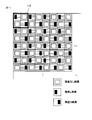
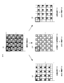
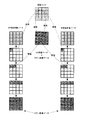
- FIG. 16 is a diagram illustrating a group of image data generated from the output of the image sensor 100 with the A-1 array described with reference to FIG. As described above, the A-1 array has the same four pixels as the Bayer array as the repeated pattern 110.
- the R pixel and the B pixel are non-parallax pixels, the Gb pixel is a parallax L pixel, and the Gr pixel is a parallax R pixel.
- the left parallax image data shown in the figure is generated.
- the left parallax image data has only pixel values of Gb pixels, and pixel values of R, Gr, and B pixels represented as empty lattices in the figure are missing. Therefore, a color image as a left parallax image cannot be generated with the left parallax image data alone. That is, the left parallax image data is generated as non-color image data.
- right parallax image data shown in the figure is generated.
- the right parallax image data has only the pixel value of the Gr pixel, and the pixel values of the R, Gb, and B pixels that are represented as empty lattices in the figure are missing. Therefore, the right parallax image data alone cannot generate a color image as a right parallax image. That is, the right parallax image data is generated as non-color image data.
- 2D image data shown in the figure is generated.
- 2D image data is assumed to be reference image data.
- the 2D image data has pixel values of R pixels and B pixels, and pixel values of Gb and Gr pixels represented as empty lattices in the figure are missing. Therefore, it is impossible to generate a color image as a 2D image with this 2D image data alone. That is, 2D image data is generated as non-color image data.
- the 2D image data, the left parallax image data, and the right parallax image data which are image data groups generated from the output of the image sensor 100 based on the A-1 array, are all non-color image data. Accordingly, it is impossible to generate a color image by using only the own data for any image data.
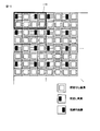
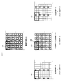
- FIG. 17 is a diagram illustrating a group of image data generated from the output of the image sensor 100 using the B′-1 array described with reference to FIG.
- the B′-1 array eight pixels in which the four pixels of the color filter array shown in FIG. Of the eight pixels, the left W pixel is a parallax L pixel, the right W pixel is a parallax R pixel, and each of the remaining R pixel, G pixel, and B pixel is a non-parallax pixel.
- the left parallax image data shown in the figure is generated.
- the left parallax image data has only the pixel value of the left W pixel, and does not have any pixel values corresponding to the R pixel, the G pixel, and the B pixel. Therefore, a color image as a left parallax image cannot be generated with the left parallax image data alone. That is, the left parallax image data is generated as non-color image data.
- right parallax image data shown in the figure is generated.
- the right parallax image data has only the pixel value of the right W pixel, and does not have any pixel values corresponding to the R pixel, the G pixel, and the B pixel. Therefore, the right parallax image data alone cannot generate a color image as a right parallax image. That is, the right parallax image data is generated as non-color image data.
- 2D image data has pixel values of R pixels, G pixels, and B pixels. If the pixel value of the lower right G pixel is interpolated as the pixel value of the W pixel represented as an empty lattice in the figure, the pixel corresponding to the Bayer array Color image data having a value. Therefore, a color image as a 2D image can be generated from only the 2D image data using a known image processing technique. In the interpolation process, not only the pixel value of the lower right G pixel but also the pixel values of other G pixels can be used.
- 2D image data is color image data
- left parallax image data and right parallax image data are non-color image data. It is.
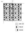
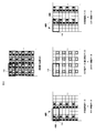
- FIG. 18 is a diagram illustrating a group of image data generated from the output of the image sensor 100 having the D-1 arrangement described with reference to FIG.
- the repeated pattern 110 includes 8 pixels in which 4 pixels in the Bayer array are two sets on the left and right.
- the left R pixel, Gb pixel, and B pixel are parallax L pixels
- the right R pixel, Gb pixel, and B pixel are parallax R pixels
- two Gr pixels are non-parallax pixels.
- the left parallax image data shown in the figure is generated.
- the left parallax image data has R, Gb, and B pixel values in the left half of the repetitive pattern 110. Then, by interpolating the pixel value of the Gb pixel as the pixel value of the Gr pixel, and further applying, for example, the left half of the repetitive pattern 110 where the pixel values are aligned to the right half as it is, the pixel value corresponding to the Bayer array Color image data with Therefore, a color image as a left parallax image can be generated only from the left parallax image data.
- right parallax image data shown in the figure is generated.
- the right parallax image data has R, Gb, and B pixel values in the right half of the repetitive pattern 110.
- the pixel value of the Gb pixel is interpolated as the pixel value of the Gr pixel, and further, for example, the right half of the repetitive pattern 110 having the same pixel value is applied as it is to the left half, the pixel value corresponding to the Bayer array Color image data with Therefore, a color image as a right parallax image can be generated only from the right parallax image data.
- 2D image data shown in the figure is generated.
- the 2D image data has only the pixel value of the Gr pixel, and the pixel values of the R, Gb, and B pixels that are represented as empty grids in the figure are missing. Therefore, it is impossible to generate a color image as a 2D image with this 2D image data alone. That is, 2D image data is generated as non-color image data.
- 2D image data is non-color image data
- left parallax image data and right parallax image data are color image data in the image data group generated from the output of the image sensor 100 having the D-1 arrangement. is there.
- At least one of the image data groups generated from the output of the image sensor 100 is non-color image data.
- a process for converting the generated non-color image data into color image data will be described below.
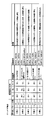
- FIG. 19 is an explanatory diagram illustrating the relationship between the subject position and the amount of parallax pixels.
- FIG. 19A shows in which region of the 2D image, the left parallax image, and the right parallax image the subject luminous flux emitted from the same minute area of the subject appears corresponding to each image data.
- the subject position is a position in the depth direction along the z-axis direction.
- the subject is present at the focus position (Focus) with respect to the photographing lens 20, and at the + focus position (Out Focus) and the -focus position (In Focus) which are non-focus positions.
- the + focus position is a position farther than the in-focus position
- the -focus position is a position closer to the in-focus position.
- a pixel block unit is used as appropriate in which four pixels of two vertical pixels and two horizontal pixels, which are one pattern of the Bayer array, are used as one pixel block.
- the subject luminous flux emitted from the same minute area appears in the same pixel block (block 2 in the figure) with respect to the 2D image.
- subject light flux emitted from the same microscopic region passes through the partial region P L of the pupil, also appear to block 2 and 2D images.
- subject light flux emitted from the same microscopic region passes through the partial region P L of the pupil, appeared to block 1, if present subject + focal position, block Appears in 3.
- the subject if the subject exists at the in-focus position, the subject luminous flux radiated from the same minute region appears in the same block corresponding to each other for any image.
- the subject if the subject exists at the out-of-focus position, it appears in blocks that are shifted from each other between the images.
- the direction of deviation is opposite between the case where the subject is present at the + focus position and the case where the subject is present at the ⁇ focus position. Further, as can be understood from the relative relationship of the subject positions in the figure, the deviation amount increases as the out-of-focus position is far away from the in-focus position.
- FIG. 19B is a diagram illustrating the relationship between the parallax pixel amounts between the images illustrated in FIG. As described above, in the right parallax image and the left parallax image, a block number different from that of the block 2 is described when the subject exists at the out-of-focus position. At this time, the amount of parallax pixels shown in the right end column of the figure represents how many blocks of the left parallax image are deviated from the 2D image as the reference image.
- the pupil partial region P L and P R of because it is set symmetrically with respect to the optical axis 21, the parallax pixel of the right image for 2D images of the same subject, the left image for 2D images Are the same in size and opposite in direction. Therefore, if the sign is reversed, the amount of parallax pixels shown in the right end column of the figure represents how many blocks of the right parallax image are deviated from the 2D image as the reference image.
- a Bayer array pattern which is one color filter pattern, is used as one pixel block and is used as a reference unit for the parallax pixel amount.
- the reference unit for the parallax pixel amount may be one pixel unit. However, it may be one pattern of the repeating pattern 110.
- the pixel block in which the subject luminous flux radiated from the same minute area of the subject appears.
- the amount of parallax pixels in each parallax block can be calculated, so which pixel block in one parallax image corresponds to which pixel block in the other parallax image I know what to do. That is, it is possible to grasp the relative positional relationship between the pixel blocks capturing the same minute area of the subject between both parallax images.
- the parallax pixel amount with respect to the reference image is half of the parallax pixel amount between the parallax images. Therefore, it is possible to enumerate how many blocks the left parallax image is shifted from the reference image over all the blocks, and the enumerated sequence forms a so-called parallax map.
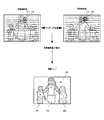
- FIG. 20 is an explanatory diagram for explaining a process for generating a parallax map.
- the parallax amount calculation unit 232 receives the left parallax image data and the right parallax image data generated by the data acquisition unit 231 and executes the following parallax map generation processing.
- the parallax amount calculation unit 232 determines a target pixel 311 having a pixel value among pixels included in the target block, and determines a local window 312 for the target pixel 311. Then, matching processing is performed between the two images using the local window 312 as a reference, and the amount of parallax pixels in the target block including the target pixel 311 is determined. Specifically, the parallax amount calculation unit 232 sets the local window 314 on the right parallax image corresponding to the local window 312 on the left parallax image, and sets the local window 314 relative to the local window 312. Searching for image regions with good matching with each other while shifting.
- the position of the local window 314 where matching is determined to be good is determined, and the coordinate value of the search pixel 313 that is the center coordinate is calculated.
- the amount of parallax pixels is determined by converting the difference between the coordinate value of the target pixel 311 and the coordinate value of the search pixel 313 in units of parallax blocks.
- the parallax amount calculation unit 232 sequentially executes the above matching process while sequentially scanning the target pixel 311 from the upper left to the lower right on the left parallax image, and calculates the parallax pixel amounts of the left parallax image and the right parallax image. To do.
- the parallax amount calculation unit 232 completes the parallax map with each of the calculated parallax pixel amounts as a half value in order to use the 2D image as a reference image.
- the parallax map is expressed as a parallax pixel amount corresponding to each subject area of the boy 301, the girl 302, the woman 303, and the background 304, which are the subjects, for example, in the example of the figure, as the above calculation result.
- the boy 301 is in focus
- the parallax pixel amount is 0 in the boy 301 area, -1 in the girl 302 area in front of the boy 301, and the woman 303 area in the back.
- the value is +1
- the background in the far distance is +4.
- FIG. 21 is a diagram showing a concept of processing for transplanting primary color information with reference to a parallax map.
- the image conversion unit 233 refers to the parallax map and converts the non-color image data into color image data.
- 2D image data is color image data
- parallax image data is non-color image data among image data generated as an image data group.
- the 2D image data that is the reference image has pixel values corresponding to each of the RGB filters in each pixel block as primary color information.
- primary color information for the pixel block (n, m) is represented as C nm .
- the image conversion unit 233 refers to the parallax map as primary color information of the pixel block (n, m) in the parallax image data, and primary color information C n ′ of the pixel block (n ′, m ′) of the 2D image data. transplant m ′ .
- the image conversion unit 233 repeats this operation for all blocks, and converts the parallax image data, which is non-color image data, into color image data.
- the image conversion unit 233 searches the pixel block (1, 1) of the 2D image data as the corresponding pixel block as it is. . Then, the image conversion unit 233, a primary color information C 11 pixel block of the 2D image data (1, 1), to obtain the primary information by transplanting into pixel blocks (1,1) of the left parallax image data.
- Image converting unit 233 since the parallax pixel amount is 0, the same applies to the pixel blocks (1,1) of the right parallax image data, transplanted primary information C 11 pixel block of the 2D image data (1,1) To do.
- the pixel block (1, 2) of the parallax map is referred to.
- the image conversion unit 233 is the pixel block on the right side of the corresponding pixel block (1, 2) of the 2D image data. Search for (1,3).
- the image conversion unit 233 a primary color information C 13 pixel block of the 2D image data (1,3), to obtain the primary information by transplanting into the left parallax image data pixel blocks (1, 2).
- the image conversion unit 233 acquires primary color information of the pixel block (1, 2) of the right parallax image data.
- the parallax pixel amount of the pixel block (1, 2) of the referenced parallax map is 1, but when the primary color information is transplanted to the right parallax pixel data, the sign is reversed. And Therefore, the image conversion unit 233 searches for the pixel block (1, 1) that is one left side of the corresponding pixel block (1, 2) of the 2D image data. Then, the image conversion unit 233, a primary color information C 11 pixel block (1,1) of the 2D image data, and acquires the primary information by transplanting into pixel blocks of the right parallax image data (1, 2).
- the image conversion unit 233 converts the primary color information C nm + k of the 2D image data into the pixel block (right parallax image data) of the pixel block (n, m) of the left parallax image data.
- the primary color information C nm-k of the 2D image data is transplanted, and the respective parallax image data primary color information is acquired. In this way, color image data is completed by transplanting primary color information into all blocks of the left parallax image data and all blocks of the right parallax image data.
- the transplantation of primary color information when the parallax image data is both non-color image data and the 2D image data is color image data has been described.
- the image sensor 100 has, for example, a B-1 array, B This is the case where the '-1 arrangement is adopted.
- the repetitive pattern 110 is 8 pixels of 2 pixels vertically and 4 pixels horizontally. Therefore, the parallax amount calculation unit 232 interpolates a missing pixel value in the parallax image data with an adjacent pixel value when four pixels of two vertical pixels and two horizontal pixels as one block as shown in FIG. Processing may be performed to calculate the parallax pixel amount corresponding to each block.
- the image conversion unit 233 refers to the parallax map, for example, the left parallax image
- the primary color information of the data is ported to 2D image data.
- the source of the primary color information may be right parallax image data, or processing such as averaging primary color information of both image data may be performed.
- the transplantation in the present embodiment is not limited to the case where the pixel value of the transplant source is simply set as the pixel value of the transplant destination, but may be the case where the pixel value of the transplant source is processed into the pixel value of the transplant destination. Including.
- the pixel value as the processing source is not limited to the pixel value of the image data to which the target pixel value belongs, and the pixel value of the transplant destination image data can also be referred to.
- Examples of processing are not limited to averaging processing, and various digital filter processing can be performed.
- the processing can be changed according to the amount of parallax pixels, and the processing can be changed according to the characteristics of the subject image, for example, the location corresponding to the edge.
- the image sensor 100 adopts, for example, a D-1 array. This is the case.
- the 2D image data generated by the data acquisition unit 231 from the pixel output of the image sensor 100 adopting the D-1 array has a pixel value of Gr pixel. Therefore, when the primary color information is transplanted from the parallax image data, the image conversion unit 233 compares the pixel value of the G pixel to be transplanted with the pixel value of the Gr pixel of the 2D image data, and adjusts the overall luminance value. You may do it.
- FIG. 22 is a diagram illustrating a concept of processing for transplanting primary color information between parallax image data and 2D image data.
- the imaging element 100 adopts, for example, an A-1 array.
- the image conversion unit 233 transplants the pixel values of the B pixel and the R pixel, which are primary color information of the 2D image data, into the left parallax image data and the right parallax image data as in the example of FIG. Further, the image conversion unit 233 refers to the parallax map, and transplants the pixel value of the Gb pixel from the left parallax image data and the pixel value of the Gr pixel from the right parallax image data in the 2D image data. In this way, each image data is converted into color image data by mutually transplanting vacancies. However, when such processing is executed, it is preferable that the areas of the opening 104 of the parallax pixel and the opening of the non-parallax pixel are equal from the viewpoint of the amount of light and the amount of blur.
- parallax amount calculation unit 232 generates a plurality of parallax maps in consideration of the combination of the corresponding left and right parallax image data.
- the parallax amount calculation unit 232 may perform interpolation in consideration of continuity with the parallax pixel amount of the adjacent pixel block. Alternatively, the parallax amount calculation unit 232 may temporarily set the parallax pixel amount of the pixel block that could not be calculated to 0, and the image processing unit 205 may perform correction processing on the generated color image data. .
- the parallax pixel amount is described as an integer value.
- the parallax pixel amount calculated by the matching process may include a decimal value.
- the image conversion unit 233 determines each primary color information having two parallax pixel amounts sandwiching the center coordinates as the distance from the center coordinates. A weighted average value is calculated according to.
- the primary color information may not be transplanted in units of pixel blocks.
- the image conversion unit 233 may perform image conversion in consideration of the difference between the center coordinates of the pixel block and the pixel position to be actually transplanted.
- the parallax amount calculation unit 232 calculates the parallax pixel amount between the same subject images based on the acquired image data.
- the amount acquired as a result of the calculation is not limited to the amount of parallax pixels, and may be an amount corresponding to the parallax between the same subject images. For example, it can be expressed by a distance corresponding to the pixel pitch, or a scale conforming to another standard can be applied.
- the 2D image data is described as the reference image data.
- any of the parallax image data may be used as the reference image data.
- each process has been described as a function of each constituent element of the digital camera 10 such as the data acquisition unit 231, the parallax amount calculation unit 232, and the image conversion unit 233 included in the image processing unit 205.
- the control program that operates the control unit 201 can cause each hardware component of the digital camera 10 to function as a component that executes the above-described processing.
- the digital camera 10 having the image sensor 100 has been described.
- the color image data conversion processing of the non-color image data is not performed by the digital camera 10 but by an external device such as a personal computer. You can go.
- an external device such as a personal computer functions as an image processing apparatus.
- the image processing apparatus acquires an image data group including reference image data and parallax image data for the same scene, any of which is non-color image data, and converts the non-color image data into color image data.
Landscapes
- Engineering & Computer Science (AREA)
- Multimedia (AREA)
- Signal Processing (AREA)
- Physics & Mathematics (AREA)
- Spectroscopy & Molecular Physics (AREA)
- Testing, Inspecting, Measuring Of Stereoscopic Televisions And Televisions (AREA)
- Color Television Image Signal Generators (AREA)
- Studio Devices (AREA)
- Stereoscopic And Panoramic Photography (AREA)
Abstract
Description
[先行技術文献]
[特許文献]
[特許文献1] 特開平8-47001号公報
Claims (11)
- 同一シーンを撮像して生成される、基準画像データと前記基準画像データの被写体像に対して視差を有する視差画像データとであって、少なくともいずれかがカラー画像を生成するための原色情報の少なくとも一部が欠落した非カラー画像データである画像データ群を取得する画像取得部と、
前記基準画像データと前記視差画像データの同一被写体像間の視差に対応する視差量を演算する視差量演算部と、
前記視差量に基づいて、前記基準画像データと前記視差画像データのいずれか一方の前記原色情報の少なくとも一部を他方へ移植して、前記非カラー画像データをカラー画像データに変換する画像変換部と
を備える画像処理装置。 - 前記画像データ群は、前記基準画像データと、前記基準画像データに対して一方向に前記視差を有する第1視差画像データおよび前記一方向とは反対の他方向に前記視差を有する第2視差画像データの少なくとも三つの画像データを含む請求項1に記載の画像処理装置。
- 前記第1視差画像データおよび前記第2視差画像データは前記非カラー画像データであり、
前記画像変換部は、前記基準画像データの前記原色情報の少なくとも一部を前記第1視差画像データおよび前記第2視差画像データへ移植して、前記第1視差画像データおよび前記第2視差画像データを前記カラー画像データに変換する請求項2に記載の画像処理装置。 - 前記第1視差画像データおよび前記第2視差画像データは、前記原色情報を有さない輝度画像データである請求項3に記載の画像処理装置。
- 前記基準画像データは前記非カラー画像データであり、
前記画像変換部は、前記第1視差画像データおよび前記第2視差画像データの少なくともいずれかの前記原色情報の少なくとも一部を前記基準画像データへ移植して、前記基準画像データを前記カラー画像データに変換する請求項2に記載の画像処理装置。 - 前記基準画像データ、前記第1視差画像データおよび前記第2視差画像データはいずれも前記非カラー画像データであり、
前記画像変換部は、前記第1視差画像データおよび前記第2視差画像データの少なくともいずれかの前記原色情報の少なくとも一部を前記基準画像データへ移植し、前記基準画像データの前記原色情報の少なくとも一部を前記第1視差画像データおよび前記第2視差画像データへ移植して、前記基準画像データ、前記第1視差画像データおよび前記第2視差画像データを前記カラー画像データに変換する請求項2に記載の画像処理装置。 - 前記視差量演算部は、前記第1視差画像データと前記第2視差画像データの前記視差量を演算してから、前記基準画像データと前記第1視差画像データおよび前記第2視差画像データのそれぞれの前記視差量を演算する請求項2から6のいずれか1項に記載の画像処理装置。
- 前記視差量演算部は、前記基準画像データに対する前記第1視差画像データおよび前記第2視差画像データの前記視差量を表す視差マップを生成し、
前記画像変換部は、前記視差マップを参照して前記原色情報を移植する請求項2から6のいずれか1項に記載の画像処理装置。 - 前記同一シーンを撮像する撮像素子と、
請求項1から8のいずれか1項に記載の画像処理装置と
を備える撮像素子であって、
前記画像取得部は、前記撮像素子の出力信号から前記画像データ群を生成して取得する撮像装置。 - 前記撮像素子は、
入射光を電気信号に光電変換する、二次元的に配列された光電変換素子と、
前記光電変換素子の少なくとも一部のそれぞれに一対一に対応して設けられた開口マスクと、
前記光電変換素子の少なくとも一部のそれぞれに一対一に対応して設けられたカラーフィルタと
を備え、
隣接するn個(nは3以上の整数)の前記光電変換素子のうち、少なくとも2つに対応して設けられたそれぞれの前記開口マスクの開口は、互いに異なる波長帯域を透過させる少なくとも3種類の前記カラーフィルタを含むカラーフィルターパターンの一パターン内に含まれると共に、前記入射光の断面領域内の互いに異なる部分領域からの光束をそれぞれ通過させるように位置づけられ、前記n個の前記光電変換素子を一組とする光電変換素子群が周期的に配列されている請求項9に記載の撮像装置。 - 同一シーンを撮像して生成される、基準画像データと前記基準画像データの被写体像に対して視差を有する視差画像データとであって、少なくともいずれかがカラー画像を生成するための原色情報の少なくとも一部が欠落した非カラー画像データである画像データ群を取得する画像取得ステップと、
前記基準画像データと前記視差画像データの同一被写体像間の視差に対応する視差量を演算する視差量演算ステップと、
前記視差量に基づいて、前記基準画像データと前記視差画像データのいずれか一方の前記原色情報の少なくとも一部を他方へ移植して、前記非カラー画像データをカラー画像データに変換する画像変換ステップと
をコンピュータに実行させる画像処理プログラム。
Priority Applications (4)
| Application Number | Priority Date | Filing Date | Title |
|---|---|---|---|
| KR1020137029935A KR20140030183A (ko) | 2011-04-14 | 2012-04-13 | 화상 처리 장치 및 화상 처리 프로그램 |
| CN201280012963.2A CN103621078B (zh) | 2011-04-14 | 2012-04-13 | 图像处理装置和图像处理程序 |
| JP2013509803A JP5979134B2 (ja) | 2011-04-14 | 2012-04-13 | 画像処理装置および画像処理プログラム |
| US14/047,269 US9706190B2 (en) | 2011-04-14 | 2013-10-07 | Image processing apparatus and image processing program |
Applications Claiming Priority (2)
| Application Number | Priority Date | Filing Date | Title |
|---|---|---|---|
| JP2011-090141 | 2011-04-14 | ||
| JP2011090141 | 2011-04-14 |
Related Child Applications (1)
| Application Number | Title | Priority Date | Filing Date |
|---|---|---|---|
| US14/047,269 Continuation US9706190B2 (en) | 2011-04-14 | 2013-10-07 | Image processing apparatus and image processing program |
Publications (1)
| Publication Number | Publication Date |
|---|---|
| WO2012140917A1 true WO2012140917A1 (ja) | 2012-10-18 |
Family
ID=47009106
Family Applications (1)
| Application Number | Title | Priority Date | Filing Date |
|---|---|---|---|
| PCT/JP2012/002600 Ceased WO2012140917A1 (ja) | 2011-04-14 | 2012-04-13 | 画像処理装置および画像処理プログラム |
Country Status (5)
| Country | Link |
|---|---|
| US (1) | US9706190B2 (ja) |
| JP (1) | JP5979134B2 (ja) |
| KR (1) | KR20140030183A (ja) |
| CN (1) | CN103621078B (ja) |
| WO (1) | WO2012140917A1 (ja) |
Cited By (2)
| Publication number | Priority date | Publication date | Assignee | Title |
|---|---|---|---|---|
| CN104756493A (zh) * | 2012-10-26 | 2015-07-01 | 株式会社尼康 | 摄像装置、图像处理装置、摄像装置的控制程序及图像处理装置的控制程序 |
| JPWO2018003501A1 (ja) * | 2016-06-28 | 2019-04-25 | ソニー株式会社 | 固体撮像装置、電子機器、レンズ制御方法および車両 |
Families Citing this family (5)
| Publication number | Priority date | Publication date | Assignee | Title |
|---|---|---|---|---|
| CN104284172A (zh) * | 2013-07-04 | 2015-01-14 | 联咏科技股份有限公司 | 影像匹配方法及立体匹配系统 |
| EP3051811A4 (en) * | 2013-09-26 | 2017-03-22 | Nikon Corporation | Image pickup element and image pickup device |
| JP6363857B2 (ja) * | 2014-03-24 | 2018-07-25 | キヤノン株式会社 | 撮像素子、撮像装置、画像処理方法、並びにプログラム |
| CN113489904B (zh) * | 2016-07-13 | 2023-07-21 | 索尼公司 | 成像装置、成像器件和图像处理装置 |
| KR20200062220A (ko) * | 2017-10-19 | 2020-06-03 | 소니 주식회사 | 전자 기기 |
Citations (4)
| Publication number | Priority date | Publication date | Assignee | Title |
|---|---|---|---|---|
| JPH0847001A (ja) * | 1994-08-01 | 1996-02-16 | Minolta Co Ltd | 立体テレビカメラ |
| JP2003007994A (ja) * | 2001-06-27 | 2003-01-10 | Konica Corp | 固体撮像素子、立体カメラ装置及び測距装置 |
| JP2009165115A (ja) * | 2007-12-12 | 2009-07-23 | Sony Corp | 撮像装置 |
| JP2010041720A (ja) * | 2008-08-06 | 2010-02-18 | Samsung Electronics Co Ltd | 立体イメージセンサのピクセルアレイ |
Family Cites Families (4)
| Publication number | Priority date | Publication date | Assignee | Title |
|---|---|---|---|---|
| US7274393B2 (en) * | 2003-02-28 | 2007-09-25 | Intel Corporation | Four-color mosaic pattern for depth and image capture |
| JP2006101224A (ja) * | 2004-09-29 | 2006-04-13 | Toshiba Corp | 画像生成装置、画像生成方法および画像生成プログラム |
| KR100603601B1 (ko) * | 2004-11-08 | 2006-07-24 | 한국전자통신연구원 | 다시점 콘텐츠 생성 장치 및 그 방법 |
| US7363157B1 (en) * | 2005-02-10 | 2008-04-22 | Sarnoff Corporation | Method and apparatus for performing wide area terrain mapping |
-
2012
- 2012-04-13 JP JP2013509803A patent/JP5979134B2/ja active Active
- 2012-04-13 CN CN201280012963.2A patent/CN103621078B/zh active Active
- 2012-04-13 WO PCT/JP2012/002600 patent/WO2012140917A1/ja not_active Ceased
- 2012-04-13 KR KR1020137029935A patent/KR20140030183A/ko not_active Withdrawn
-
2013
- 2013-10-07 US US14/047,269 patent/US9706190B2/en active Active
Patent Citations (4)
| Publication number | Priority date | Publication date | Assignee | Title |
|---|---|---|---|---|
| JPH0847001A (ja) * | 1994-08-01 | 1996-02-16 | Minolta Co Ltd | 立体テレビカメラ |
| JP2003007994A (ja) * | 2001-06-27 | 2003-01-10 | Konica Corp | 固体撮像素子、立体カメラ装置及び測距装置 |
| JP2009165115A (ja) * | 2007-12-12 | 2009-07-23 | Sony Corp | 撮像装置 |
| JP2010041720A (ja) * | 2008-08-06 | 2010-02-18 | Samsung Electronics Co Ltd | 立体イメージセンサのピクセルアレイ |
Cited By (4)
| Publication number | Priority date | Publication date | Assignee | Title |
|---|---|---|---|---|
| CN104756493A (zh) * | 2012-10-26 | 2015-07-01 | 株式会社尼康 | 摄像装置、图像处理装置、摄像装置的控制程序及图像处理装置的控制程序 |
| CN104756493B (zh) * | 2012-10-26 | 2017-03-08 | 株式会社尼康 | 摄像装置、图像处理装置、摄像装置的控制程序及图像处理装置的控制程序 |
| US9693036B2 (en) | 2012-10-26 | 2017-06-27 | Nikon Corporation | Imaging apparatus, image processing device, computer-readable medium having stored thereon an imaging apparatus controlling program, and computer-readable medium having stored thereon an image processing program |
| JPWO2018003501A1 (ja) * | 2016-06-28 | 2019-04-25 | ソニー株式会社 | 固体撮像装置、電子機器、レンズ制御方法および車両 |
Also Published As
| Publication number | Publication date |
|---|---|
| KR20140030183A (ko) | 2014-03-11 |
| CN103621078A (zh) | 2014-03-05 |
| US20140036043A1 (en) | 2014-02-06 |
| JPWO2012140917A1 (ja) | 2014-07-28 |
| JP5979134B2 (ja) | 2016-08-24 |
| CN103621078B (zh) | 2016-01-13 |
| US9706190B2 (en) | 2017-07-11 |
Similar Documents
| Publication | Publication Date | Title |
|---|---|---|
| JP5915537B2 (ja) | 撮像素子、及び、撮像装置 | |
| JP5804055B2 (ja) | 画像処理装置、画像処理方法およびプログラム | |
| JP5979134B2 (ja) | 画像処理装置および画像処理プログラム | |
| WO2013136819A1 (ja) | 撮像素子、撮像装置および撮像システム | |
| WO2013161313A1 (ja) | 画像処理装置、撮像装置および画像処理プログラム | |
| JPWO2013114895A1 (ja) | 撮像装置 | |
| JP6036840B2 (ja) | 撮像装置、画像処理装置、撮像装置の制御プログラムおよび画像処理装置の制御プログラム | |
| JP5874729B2 (ja) | 撮像装置 | |
| JPWO2013057859A1 (ja) | 撮像素子 | |
| JP6197316B2 (ja) | 撮像素子および撮像装置 | |
| JP5978736B2 (ja) | 画像処理装置、撮像装置および画像処理プログラム | |
| JP5979137B2 (ja) | 撮像装置および撮像装置の制御プログラム | |
| JP5874334B2 (ja) | 画像処理装置、撮像装置、画像処理プログラムおよび撮像装置の制御プログラム | |
| JP5978737B2 (ja) | 画像処理装置、撮像装置および画像処理プログラム | |
| JP5978738B2 (ja) | 画像処理装置、撮像装置および画像処理プログラム | |
| JP2012212975A (ja) | 撮像装置および撮像装置の制御プログラム | |
| JP6205770B2 (ja) | 撮像素子および撮像システム | |
| JP6019611B2 (ja) | 撮像装置 | |
| JP2013090265A (ja) | 画像処理装置および画像処理プログラム | |
| JP5978735B2 (ja) | 画像処理装置、撮像装置および画像処理プログラム | |
| JP2013150055A (ja) | 画像処理装置、画像処理方法、及び、プログラム | |
| JP2013162362A (ja) | 撮像装置および撮像プログラム |
Legal Events
| Date | Code | Title | Description |
|---|---|---|---|
| 121 | Ep: the epo has been informed by wipo that ep was designated in this application |
Ref document number: 12770574 Country of ref document: EP Kind code of ref document: A1 |
|
| ENP | Entry into the national phase |
Ref document number: 2013509803 Country of ref document: JP Kind code of ref document: A |
|
| NENP | Non-entry into the national phase |
Ref country code: DE |
|
| ENP | Entry into the national phase |
Ref document number: 20137029935 Country of ref document: KR Kind code of ref document: A |
|
| 122 | Ep: pct application non-entry in european phase |
Ref document number: 12770574 Country of ref document: EP Kind code of ref document: A1 |