WO2012140818A1 - 補聴器および振動検出方法 - Google Patents
補聴器および振動検出方法 Download PDFInfo
- Publication number
- WO2012140818A1 WO2012140818A1 PCT/JP2012/001157 JP2012001157W WO2012140818A1 WO 2012140818 A1 WO2012140818 A1 WO 2012140818A1 JP 2012001157 W JP2012001157 W JP 2012001157W WO 2012140818 A1 WO2012140818 A1 WO 2012140818A1
- Authority
- WO
- WIPO (PCT)
- Prior art keywords
- vibration
- hearing aid
- signal
- vibration noise
- noise
- Prior art date
Links
Images


Classifications
-
- H—ELECTRICITY
- H04—ELECTRIC COMMUNICATION TECHNIQUE
- H04R—LOUDSPEAKERS, MICROPHONES, GRAMOPHONE PICK-UPS OR LIKE ACOUSTIC ELECTROMECHANICAL TRANSDUCERS; DEAF-AID SETS; PUBLIC ADDRESS SYSTEMS
- H04R25/00—Deaf-aid sets, i.e. electro-acoustic or electro-mechanical hearing aids; Electric tinnitus maskers providing an auditory perception
- H04R25/30—Monitoring or testing of hearing aids, e.g. functioning, settings, battery power
-
- G—PHYSICS
- G10—MUSICAL INSTRUMENTS; ACOUSTICS
- G10L—SPEECH ANALYSIS OR SYNTHESIS; SPEECH RECOGNITION; SPEECH OR VOICE PROCESSING; SPEECH OR AUDIO CODING OR DECODING
- G10L21/00—Processing of the speech or voice signal to produce another audible or non-audible signal, e.g. visual or tactile, in order to modify its quality or its intelligibility
- G10L21/02—Speech enhancement, e.g. noise reduction or echo cancellation
- G10L21/0208—Noise filtering
-
- H—ELECTRICITY
- H04—ELECTRIC COMMUNICATION TECHNIQUE
- H04R—LOUDSPEAKERS, MICROPHONES, GRAMOPHONE PICK-UPS OR LIKE ACOUSTIC ELECTROMECHANICAL TRANSDUCERS; DEAF-AID SETS; PUBLIC ADDRESS SYSTEMS
- H04R25/00—Deaf-aid sets, i.e. electro-acoustic or electro-mechanical hearing aids; Electric tinnitus maskers providing an auditory perception
- H04R25/40—Arrangements for obtaining a desired directivity characteristic
- H04R25/407—Circuits for combining signals of a plurality of transducers
-
- G—PHYSICS
- G10—MUSICAL INSTRUMENTS; ACOUSTICS
- G10L—SPEECH ANALYSIS OR SYNTHESIS; SPEECH RECOGNITION; SPEECH OR VOICE PROCESSING; SPEECH OR AUDIO CODING OR DECODING
- G10L21/00—Processing of the speech or voice signal to produce another audible or non-audible signal, e.g. visual or tactile, in order to modify its quality or its intelligibility
- G10L21/02—Speech enhancement, e.g. noise reduction or echo cancellation
- G10L21/0208—Noise filtering
- G10L21/0216—Noise filtering characterised by the method used for estimating noise
- G10L2021/02161—Number of inputs available containing the signal or the noise to be suppressed
- G10L2021/02165—Two microphones, one receiving mainly the noise signal and the other one mainly the speech signal
-
- H—ELECTRICITY
- H04—ELECTRIC COMMUNICATION TECHNIQUE
- H04R—LOUDSPEAKERS, MICROPHONES, GRAMOPHONE PICK-UPS OR LIKE ACOUSTIC ELECTROMECHANICAL TRANSDUCERS; DEAF-AID SETS; PUBLIC ADDRESS SYSTEMS
- H04R2430/00—Signal processing covered by H04R, not provided for in its groups
- H04R2430/03—Synergistic effects of band splitting and sub-band processing
Definitions
- the present invention relates to a hearing aid including two microphones and a vibration detection method thereof.
- Hearing aids may cause feedback when attached to or removed from the ear. This is because the acoustic transfer function (hereinafter also referred to as “acoustic system”) between the microphone that collects sound and the receiver that outputs sound changes greatly.
- acoustic system acoustic transfer function
- Patent Document 1 Techniques for howling suppression control in a hearing aid are described in Patent Document 1 and Patent Document 2, for example.
- Patent Document 1 determines that howling has occurred when the state in which the level of a specific frequency signal protrudes in the collected sound signal from the microphone, and reduces the volume of the acoustic signal.
- the technique of patent document 2 provides the touch sensor by an electrode in a hearing aid, detects the timing of desorption
- Patent Document 1 cannot detect howling until after a certain level of howling sound continues, and it is difficult to suppress howling at the initial stage of occurrence.
- the technique described in Patent Document 2 must be provided with a new sensor other than a microphone called a touch sensor, which can be an obstacle to miniaturization, weight reduction, and power saving required for hearing aids.
- the vibration generated when the outside of the hearing aid casing contacts the hand or ear (hereinafter referred to as “contact vibration”) is transmitted to the microphone as a solid-borne sound and superimposed on the collected sound signal as noise. And howling. If the contact vibration can detect noise (hereinafter referred to as “contact vibration noise”) due to the contact vibration from the collected sound signal, a large change in the acoustic system can be estimated with high accuracy.
- detection and suppression of contact vibration noise makes it possible to suppress howling from the initial generation without providing a new sensor. Therefore, it is desirable for hearing aids to detect and suppress contact vibration noise from the collected sound signal.
- An object of the present invention is to provide a hearing aid and a vibration detection method capable of detecting contact vibration noise from a collected sound signal.
- the hearing aid of the present invention includes two microphones, and a vibration component extraction unit that extracts uncorrelated components between the two sound pickup signals as vibration components for each band from the sound pickup signals acquired by the two microphones, respectively. Based on the vibration component for each band extracted by the vibration component extraction unit, a vibration noise identification unit that determines whether or not contact vibration noise has occurred, and an acoustic signal obtained by hearing processing the two collected sound signals.
- the sound signal includes a sound signal processing unit that performs processing according to whether or not the contact vibration noise is generated, and a receiver that converts the sound signal into sound.
- the vibration detection method of the present invention is a vibration detection method in a hearing aid equipped with two microphones, and the uncorrelated components between the two sound pickup signals are obtained from the sound pickup signals respectively acquired by the two microphones. Separately extracting as a vibration component, determining whether contact vibration noise has occurred based on the extracted vibration component for each band, and hearing-processing the two collected sound signals to obtain an acoustic signal A step of performing processing on the acoustic signal according to whether or not the contact vibration noise is generated.
- contact vibration noise can be detected from the collected sound signal.
- the block diagram which shows an example of a structure of the low region vibration component extraction part and the high region vibration component extraction part in Embodiment 2 of this invention
- the flowchart which shows an example of operation
- the figure which shows an example of the state of each signal in case the spontaneous speech noise is contained in Embodiment 2 of this invention.
- the figure which shows an example of the state of each signal in case the contact vibration noise in Embodiment 2 of this invention is included.
- the block diagram which shows an example of a structure of the hearing aid which concerns on Embodiment 3 of this invention.
- the block diagram which shows an example of a structure of the 1st and 2nd band signal extraction part using the filter bank in Embodiment 3 of this invention The block diagram which shows an example of a structure of the 1st and 2nd band signal extraction part using FFT in Embodiment 3 of this invention
- the figure which shows an example of the input / output characteristic of the audio limiter in Embodiment 4 of this invention The flowchart which shows an example of the volume suppression process which the hearing aid which concerns on Embodiment 4 of this invention performs.
- Block diagram showing an example of the configuration of a hearing aid according to Embodiment 5 of the present invention Block diagram showing an example of the configuration of a howling canceller according to Embodiment 5 of the present invention
- the flowchart which shows an example of the volume suppression process which the hearing aid which concerns on Embodiment 5 of this invention performs.
- Embodiment 1 of the present invention is an example of a basic aspect of the present invention
- Embodiments 2 to 5 of the present invention are examples of specific aspects of the present invention.
- the sound included in the collected sound signal of the hearing aid is broadly classified into an air propagation sound and a solid propagation sound.
- the air propagation sound is a sound transmitted to the microphone of the hearing aid through the air, for example, a speech voice of the conversation partner of the user wearing the hearing aid.
- the solid propagation sound is a sound transmitted to the hearing aid microphone through the solid including the hearing aid itself.
- the component of the collected sound signal due to the air propagation sound is referred to as “sound component”, and the component of the sound collected signal due to the solid propagation sound is referred to as “vibration component”.
- Solid propagation sound is classified into user's own speech (hereinafter referred to as “self-speech”) and sound caused by contact vibration caused by contact between the hand and the hearing aid housing when the hearing aid is attached / detached. That is, the vibration component is classified into self-speech (hereinafter referred to as “speech noise”) and contact vibration noise.
- Embodiment 1 The hearing aid according to Embodiment 1 of the present invention is attached to either the left or right ear of the user, and performs sound collection and output the sound that has undergone predetermined processing into the ear hole of the wearer. It is an example applied to an ear-hook type hearing aid.
- Each unit of the acoustic processing device described below includes, for example, a hardware including a microphone, a receiver, and a central processing unit (CPU) disposed in the hearing aid and a storage medium such as a ROM (read only memory) storing a control program. Realized by hardware.
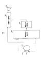
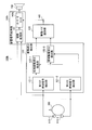
- FIG. 1 is a block diagram showing a configuration of a hearing aid according to the present embodiment.
- the hearing aid 100 includes first and second microphones 110-1 and 110-2 (two microphones 110), a vibration component extraction unit 120, a vibration noise identification unit 130, an acoustic signal processing unit 140, and a receiver 150.
- the first and second microphones 110-1 and 110-2 are arranged at different positions inside the hearing aid 100, and each collects sound to obtain a collected sound signal.
- the vibration component extraction unit 120 uses a component having a low correlation between the two collected sound signals (hereinafter referred to as “non-correlated component”) from the collected sound signals acquired by the first and second microphones 110-1 and 110-2, respectively. Are extracted as vibration components for each band.
- the uncorrelated component is a component other than the air-borne sound, and mainly corresponds to a vibration component that directly drives the diaphragm of the microphone 110 or a thermal noise component unique to the microphone 110. Since the level of the thermal noise component is low, an uncorrelated component with a certain level or more is almost equal to the vibration component.
- the vibration noise identification unit 130 determines whether or not contact vibration noise has occurred based on the vibration component for each band extracted by the vibration component extraction unit 120. For example, when only the vibration component in the low frequency band is detected among the vibration components for each band, the vibration noise identification unit 130 distinguishes the vibration component from the contact vibration noise as the spontaneous speech noise. Further, for example, the vibration noise identification unit 130 determines that contact vibration noise has occurred on the condition that the level of the high frequency band of the vibration component is relatively greater than the level of the low frequency band of the vibration component. .
- the acoustic signal processing unit 140 performs processing according to the presence or absence of occurrence of contact vibration noise on the acoustic signal when generating the acoustic signal by performing hearing processing on the two collected sound signals. For example, the acoustic signal processing unit 140 controls the volume of the acoustic signal according to whether or not the contact vibration noise is generated.
- the receiver 150 converts an acoustic signal into sound.
- the hearing aid 100 can extract the vibration component of the collected sound signal with high accuracy by extracting the uncorrelated component between the two collected sound signals.
- the hearing aid 100 can accurately identify the vibration component based on the relative magnitude of the high frequency band level of the vibration component with respect to the low frequency band level of the vibration component. Specifically, the hearing aid 100 can identify whether the vibration component is spontaneous speech noise or contact vibration noise (hereinafter collectively referred to as “noise” as appropriate).
- the hearing aid 100 extracts a non-correlated component between collected sound signals as a vibration component and identifies noise based on the level of the high frequency band. Can be detected. That is, the hearing aid 100 according to the present embodiment can prevent howling as a result by detecting contact vibration noise at an early stage of generation.
- Embodiment 2 The hearing aid according to Embodiment 2 of the present invention is an example applied to an ear-hook type hearing aid that performs hearing aid processing and howling suppression processing.
- the hearing aid according to the present embodiment extracts a vibration component for each band from the collected sound signal and identifies whether it is self-speech noise or contact vibration noise. Then, the hearing aid according to the present embodiment is assumed to be desorbed from the ear of the hearing aid when contact vibration noise is detected, and howling due to a change in the acoustic system is estimated to suppress howling. The process is performed.
- Each part of the sound processing device described below is realized by hardware including a storage medium such as a microphone, a receiver, a CPU, and a ROM storing a control program, which are arranged inside the hearing aid.
- a storage medium such as a microphone, a receiver, a CPU, and a ROM storing a control program, which are arranged inside the hearing aid.
- FIG. 2 is a block diagram showing the configuration of the hearing aid according to the present embodiment.
- the hearing aid 100 includes first and second microphones 110-1 and 110-2 (two microphones 110), a vibration component extraction unit 120, a vibration noise identification unit 130, an acoustic signal processing unit 140, and a receiver 150.
- the first and second microphones 110-1 and 110-2 are arranged at different positions inside the hearing aid 100, and each collects sound to obtain a collected sound signal.
- the first microphone 110-1 outputs the acquired sound collection signal (hereinafter referred to as “first sound collection signal”) to the vibration component extraction unit 120 and the acoustic signal processing unit 140.
- the second microphone 110-2 outputs the acquired sound collection signal (hereinafter referred to as “second sound collection signal”) to the vibration component extraction unit 120 and the acoustic signal processing unit 140.
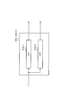
- FIG. 3 is a diagram showing an example of the appearance of a hearing aid.
- the hearing aid 100 includes a hearing aid body 310, an acoustic tube 320, and an ear tip 330.
- the hearing aid body 310 is hung on the auricle.
- the ear tip 330 is embedded in the ear hole while the hearing aid main body 310 is hung on the auricle.
- the first microphone 110-1 and the second microphone 110-2 are omnidirectional microphones housed in the hearing aid main body 310 of the hearing aid 100, respectively.
- the first microphone 110-1 and the second microphone 110-2 collect ambient sounds through holes such as slits.
- the receiver 150 described later is a speaker housed in the hearing aid main body 310 of the hearing aid 100.
- the sound amplified from the receiver 150 passes through the acoustic tube 320 and is output from the ear chip 330 into the ear hole.
- Hearing aids equipped with two such omnidirectional microphones are widely used. This is because the sound directivity can be synthesized from the two collected sound signals and a sound signal having directivity can be output at a low cost with a simple device.
- FIG. 4 is a diagram showing a wearing state of the hearing aid.
- the hearing aid 100 is attached to the left ear of the user 200, for example, and fixed to the left side of the user 200's head.
- the vibration component extraction unit 120 uses a component having a low correlation between the two collected sound signals (hereinafter referred to as “non-correlated component”) from the collected sound signals acquired by the first and second microphones 110-1 and 110-2, respectively.
- non-correlated component a component having a low correlation between the two collected sound signals
- vibration components for each band are extracted as vibration components for each band.
- vibration components are extracted in two bands, a low-frequency vibration component and a high-frequency vibration component, as vibration components for each band will be described.
- the vibration component extraction unit 120 performs signal component extraction and vibration component extraction for each band.
- the vibration component extraction unit 120 includes a first band signal extraction unit 121-1 and a second band signal extraction unit 121-2 (band signal extraction unit), a low-frequency vibration component extraction unit 122-1, and a high-frequency vibration component.
- An extraction unit 122-2 (vibration component extraction unit).
- the low frequency band (hereinafter referred to as “low band” as appropriate) is a band including the vibration component of the spontaneous speech and the vibration component of the contact vibration, for example, a band of about 1 kHz or less.
- the high frequency band (hereinafter referred to as “high band” as appropriate) is a band that does not include the vibration component of the self-speech voice but includes the vibration component of the contact vibration, for example, a band that exceeds about 1 kHz.
- the first band signal extraction unit 121-1 extracts a low frequency band signal from the first collected sound signal, and extracts the extracted signal (hereinafter referred to as “first low band signal”) as a low band vibration component.
- the data is output to the extraction unit 122-1.
- the first band signal extraction unit 121-1 extracts a high frequency band signal from the first collected sound signal, and extracts the extracted signal (hereinafter referred to as “first high frequency signal”) as a high frequency band.
- the second band signal extraction unit 121-2 extracts a low frequency band signal from the second collected sound signal, and extracts the extracted signal (hereinafter referred to as “second low band signal”) as a low band vibration component.
- the data is output to the extraction unit 122-1.
- the second band signal extraction unit 121-2 extracts a high frequency band signal from the second collected sound signal, and extracts the extracted signal (hereinafter referred to as “second high frequency signal”) as a high frequency band.
- the first band signal extraction unit 121-1 and the second band signal extraction unit 121-2 have, for example, the same configuration.
- FIG. 5 is a block diagram showing an example of the configuration of the first and second band signal extraction units 121-1 and 121-2.
- each of the first and second band signal extraction units 121-1 and 121-2 includes, for example, two band filters having different pass bands.
- the first band signal extraction unit 121-1 includes a low-pass filter (LPF: Low Pass Filter) 410-1 and a high-pass filter (HPF: High Pass Filter) 410-2.
- the second band signal extraction unit 121-2 includes a low-pass filter (LPF) 410-1 and a high-pass filter (HPF) 410-2.
- the low-pass filter 410-1 passes only the low-frequency band component of the first sound collection signal (second sound collection signal) and outputs it as the first low-frequency signal (second low-frequency signal). To do.
- the high-pass filter 410-2 passes only the component in the high frequency band of the first sound collection signal (second sound collection signal) and outputs it as the first high-frequency signal (second high-frequency signal). To do.
- the first and second band signal extraction units 121-1 and 121-2 may perform extraction of a low-frequency signal and a high-frequency signal by FFT (Fast Fourier Transform) that converts a time waveform into a frequency spectrum. Good.
- FFT Fast Fourier Transform
- the low-frequency vibration component extraction unit 122-1 uses a signal indicating the level of the extracted vibration component (hereinafter referred to as “low-frequency vibration component”) (hereinafter referred to as “low-frequency vibration component level signal”) as a vibration noise identification unit. To 130.
- the low-frequency vibration component extracting unit 122-1 first includes a signal indicating the level of the first low-frequency signal (hereinafter referred to as “first low-frequency signal”) and the second low-frequency signal.
- first low-frequency signal a signal indicating the level of the first low-frequency signal
- second low frequency level signal A signal indicating the level of the signal
- the first low-frequency signal is a signal obtained by smoothing the square value of the first low-frequency signal.
- the second low-frequency signal is a signal obtained by smoothing the square value of the second low-frequency signal.
- the low-frequency vibration component extraction unit 122-1 extracts an uncorrelated component between the first low-frequency level signal and the second low-frequency level signal as a low-frequency vibration component level.
- the high frequency vibration component extracting unit 122-2 extracts a high frequency band vibration component from the first high frequency signal and the second high frequency signal. Further, the high frequency vibration component extraction unit 122-2 uses a signal (hereinafter referred to as “high frequency vibration component level signal”) indicating the level of the extracted vibration component (hereinafter referred to as “high frequency vibration component”) as a vibration noise identification unit. To 130.
- high frequency vibration component level signal indicating the level of the extracted vibration component
- the high-frequency vibration component extracting unit 122-2 firstly includes a signal indicating the level of the first high-frequency signal (hereinafter referred to as “first high-frequency signal”) and the second high frequency signal.
- first high-frequency signal a signal indicating the level of the first high-frequency signal
- second high frequency level signal A signal indicating the level of the signal
- the first high frequency signal is a signal obtained by smoothing the square value of the first high frequency signal.
- the second high frequency level signal is a signal obtained by smoothing the square value of the second high frequency signal.
- the high frequency vibration component extracting unit 122-2 extracts an uncorrelated component between the first high frequency level signal and the second high frequency level signal as a high frequency vibration component.
- the air-borne sound has a high correlation between the first and second microphones 110-1 and 110-2. Further, the solid propagation sound has a low correlation between the first and second microphones 110-1 and 110-2. That is, the low-frequency vibration component extraction unit 122-1 and the high-frequency vibration component extraction unit 122-2 pay attention to the difference in correlation between the air propagation sound and the solid propagation sound (vibration noise), Extract.
- the low-frequency vibration component extraction unit 122-1 and the high-frequency vibration component extraction unit 122-2 have the same configuration, although the frequency bands of the input signals are different.
- FIG. 6 is a block diagram showing an example of the configuration of the low-frequency vibration component extraction unit and the high-frequency vibration component extraction units 122-1 and 122-2.
- the low-frequency vibration component extraction unit and the high-frequency vibration component extraction units 122-1 and 122-2 include a first square value calculation unit 510-1 and a second square value calculation unit 510-2.
- the first square value calculation unit 510-1 outputs a signal indicating the square value of the first low-frequency signal (first high-frequency signal) to the first smoothing unit 520-1.
- the second square value calculation unit 510-2 outputs a signal indicating the square value of the second low-frequency signal (second high-frequency signal) to the second smoothing unit 520-2.
- the first smoothing unit 520-1 smoothes a signal indicating the square value of the first low-frequency signal (first high-frequency signal) by, for example, LPF, and generates a first low-frequency signal (first Are output to the adder 540.
- the second smoothing unit 520-2 smoothes a signal indicating the square value of the second low-frequency signal (second high-frequency signal) by, for example, LPF, and outputs a second low-frequency signal (second As a high frequency level signal) to the variable multiplier 530.
- time constant in smoothing mitigates the effect that the correlation between signals decreases due to the arrival time difference of air-borne sound due to the interval between the first microphone 110-1 and the second microphone 110-2.
- the time constant in the smoothing is set to an appropriate value such that the air propagation sound is suitably canceled in the adder 540 at the subsequent stage.
- variable multiplier 530 obtains a corrected multiplication value from the difference value output from the adder 540, and multiplies the obtained corrected multiplication value by the second low-frequency signal (second high-frequency signal). Variable multiplier 530 outputs a signal obtained by multiplying the second low-frequency signal (second high-frequency signal) by the corrected multiplication value to adder 540.
- the adder 540 multiplies the first low-frequency signal (first high-frequency signal) and the correction multiplication value to perform the amplitude correction by multiplying the second low-frequency signal (second high-frequency signal).
- Signal is output to absolute value calculation section 550 and variable multiplier 530.
- the output signal of the adder 540 is an uncorrelated component between the first low frequency level signal (first high frequency signal) and the second low frequency signal (second high frequency signal) ( (Correlated component for each band).
- variable multiplier 530 and the adder 540 calculate a corrected multiplication value from the difference signal of the adder 540 and multiply this by the second low frequency level signal (second high frequency signal) to correct the sound pressure sensitivity. I do. Thereby, the variable multiplier 530 and the adder 540 extract uncorrelated components in the low frequency band (high frequency band).
- This sound pressure sensitivity correction includes correction of sensitivity variations of the first and second microphones 110-1 and 110-2 caused by manufacturing processes and the like.
- this sound pressure sensitivity correction corrects sensitivity variations that occur due to differences in acoustic wraparound between the first and second microphones 110-1 and 110-2 due to the influence of ears and the like. Including.
- this sound pressure sensitivity correction it is possible to appropriately cancel the components of the air propagation sound that are included in the first and second collected sound signals and have a high correlation, and extract the uncorrelated components.
- variable multiplier 530 updates the correction multiplication value (variable multiplication value) so that the value of the difference signal approaches zero.
- the variable multiplier 530 decreases the gain (correction multiplication value), for example.
- the smoothed second low-frequency signal (second high-frequency signal) is the smoothed first low-frequency signal (first high-frequency signal). Signal).
- variable multiplier 530 increases the gain (correction multiplication value), for example. As a result, it is possible to correct the sound pressure sensitivity between the microphones 110 by using the air propagation sound having a high correlation between the microphones 110 that are picked up during normal use. This makes it possible to extract only uncorrelated components.
- the absolute value calculation unit 550 calculates and outputs a signal indicating the absolute value of the uncorrelated component for each band as a low-frequency vibration component level signal (high-frequency vibration component level signal).
- the vibration noise identification unit 130 determines that contact vibration noise has occurred on the condition that the high frequency band level of the vibration component is relatively higher than the low frequency band level of the vibration component. Then, the vibration noise identifying unit 130 outputs the identification result to the acoustic signal processing unit 140 via the output unit 160.
- the vibration noise identification unit 130 determines that contact vibration noise has occurred on the condition that the ratio of the high-frequency vibration component level to the low-frequency vibration component level exceeds a predetermined threshold.
- the vibration noise identification unit 130 determines that howling due to a change in the acoustic system occurs, and performs execution of predetermined processing for suppressing howling as acoustic signal processing. Instruct the unit 140.
- the acoustic signal processing unit 140 performs processing according to the presence or absence of occurrence of contact vibration noise on the acoustic signal when generating the acoustic signal by performing hearing processing on the two collected sound signals.
- the acoustic signal processing unit 140 includes a hearing aid processing unit 141 and a suppression processing unit 142.
- the hearing aid processing unit 141 performs predetermined hearing aid processing such as loud sound processing from the first sound collection signal and the second sound collection signal, generates an acoustic signal, and outputs it to the suppression processing unit 142.
- the suppression processing unit 142 transfers the acoustic signal to the receiver 150. In addition, when there is an instruction from the vibration noise identification unit 130, the suppression processing unit 142 performs a predetermined process for suppressing howling on the acoustic signal.
- the receiver 150 converts the acoustic signal subjected to the hearing aid processing into sound and outputs it as a hearing aid sound.
- the self-speaking voice originally has less energy in the band of 1 kHz or more due to the nature of the voice.
- vibration components transmitted to the microphone 110 in the spontaneous speech are concentrated in a band of 1 kHz or less due to the influence of bone conduction.
- the vibration component of the contact vibration is pulsed vibration noise, it is distributed in a wide band over a high frequency of several hertz to 1 kHz or more.
- the hearing aid 100 distinguishes the spontaneous speech noise and the contact vibration noise by setting the band below about 1 kHz as a low band and the band exceeding about 1 kHz as a high band, and analyzing each vibration component. can do. Specifically, when the vibration noise identification unit 130 detects only the vibration component in the low frequency band among the vibration components for each band, the hearing aid 100 uses the vibration component as a self-speaking noise, and the contact vibration noise. And can be distinguished.
- a high-frequency signal with a short wavelength is easily affected by unevenness of the head and auricle surrounding the hearing aid, and is also affected by a phase difference due to the microphone position. For this reason, in uncorrelated component extraction, components other than the vibration component may be erroneously output as a high-frequency vibration level signal even if the difference between the first and second high-frequency signals is taken.
- the hearing aid 100 is not merely presence / absence of high-frequency vibration noise, but whether the vibration noise level is high and the high-frequency vibration noise level is relatively high with respect to the low-frequency vibration noise level. Based on this, contact vibration noise is identified. In other words, the hearing aid 100 detects the vibration level in the low frequency included in both the contact vibration noise and the spontaneous speech noise, and then identifies the vibration noise in the procedure of detecting the vibration level in the high frequency.
- Such a hearing aid 100 extracts a non-correlated component between collected sound signals as a vibration component, and identifies noise based on the level of the high frequency band. Therefore, the contact vibration noise can be detected from the collected sound signal. . Further, in addition to the original hearing aid processing, the hearing aid 100 performs processing for suppressing howling on the acoustic signal when detecting contact vibration noise, so that howling can be reduced.
- FIG. 7 is a flowchart showing an example of the operation of the hearing aid 100.
- the hearing aid 100 starts the operation shown in FIG. 7 when the power switch or howling suppression function is turned on, and ends when the power switch or howling suppression function is turned off.
- the hearing aid 100 continuously acquires the first sound collection signal and the second sound collection signal while performing the operation illustrated in FIG. 7, performs a hearing aid process, generates an acoustic signal, and performs hearing aid. Sound shall be output.
- step S1100 the first band signal extraction unit 121-1 extracts the first low frequency signal and the first high frequency signal from the first sound pickup signal. Further, the second band signal extraction unit 121-2 extracts the second low frequency signal and the second high frequency signal from the second collected sound signal.
- step S1200 the low-frequency vibration component extracting unit 122-1 uses the square value of the first low-frequency signal and the square value of the second low-frequency signal as the first low-frequency signal before smoothing and It calculates as a 2nd low-pass level signal. Further, the high frequency vibration component extracting unit 122-2 uses the square value of the first high frequency signal and the square value of the second high frequency signal as the first high frequency level signal and the second high frequency signal before smoothing. Calculated as a range level signal.
- step S1300 low-frequency vibration component extraction unit 122-1 smoothes the first low-frequency signal and the second low-frequency signal before smoothing, and first smoothed low-frequency signal is obtained. A band level signal and a second low band level signal are calculated. Further, the high-frequency vibration component extracting unit 122-2 smoothes the first high-frequency signal before smoothing and the second high-frequency signal, respectively, and the first high-frequency signal after smoothing and A second high level signal is calculated.
- step S1400 the low-frequency vibration component extracting unit 122-1 extracts the uncorrelated component in the low-frequency band from the first low-frequency level signal and the second low-frequency signal after smoothing. As a vibration component. Further, the high-frequency vibration component extraction unit 122-2 uses the uncorrelated component in the high frequency band as the vibration component in the high frequency band from the smoothed first high frequency level signal and second high frequency level signal. Extract.
- step S1500 the low-frequency vibration component extraction unit 122-1 calculates a signal obtained from the absolute value of the uncorrelated component in the low-frequency band as a low-frequency vibration component level signal. Further, the high frequency vibration component extracting unit 122-2 calculates a signal obtained by taking the absolute value of the uncorrelated component in the high frequency band as a high frequency vibration component level signal. That is, the low-frequency vibration component extraction unit 122-1 and the high-frequency vibration component extraction unit 122-2 convert the low-frequency uncorrelated component and the high-frequency uncorrelated component into the low-frequency vibration component level low_lev and the high-frequency vibration component level. Each level is converted to high_lev.
- step S1600 the vibration noise identification unit 130 determines whether or not the low-frequency vibration component level low_lev indicated by the low-frequency vibration component level signal is equal to or higher than a predetermined first threshold value thr1.
- the vibration noise identification unit 130 has the low-frequency vibration component level low_lev equal to or higher than the first threshold thr1 when the low-frequency vibration component level low_lev is equal to or higher than the first threshold thr1 for a predetermined time or longer. You may make it judge.
- the vibration noise identification unit 130 proceeds to step S1700. If the low-frequency vibration component level low_lev is equal to or higher than the first threshold value thr1 (S1600: YES), the vibration noise identification unit 130 proceeds to step S1800.
- step S1700 the vibration noise identification unit 130 determines that there is no vibration noise, and proceeds to step S2100.
- step S1800 the vibration noise identification unit 130 obtains a ratio of the high-frequency vibration component level high_lev to the low-frequency vibration component level low_lev (high_lev / low_lev, hereinafter referred to as “band level ratio”). Then, the vibration noise identification unit 130 determines whether or not the obtained band level ratio is equal to or greater than a predetermined second threshold value thr2.
- the vibration noise identifying unit 130 proceeds to step S1900. If the band level ratio (high_lev / low_lev) is equal to or greater than the second threshold thr2 (S1800: YES), the vibration noise identifying unit 130 proceeds to step S2000.
- step S1900 the vibration noise identification unit 130 determines that there is vibration noise, and the vibration noise is self-utterance noise, and proceeds to step S2100.
- step S2000 the vibration noise identifying unit 130 determines that there is vibration noise, and the vibration noise is contact vibration noise, and proceeds to step S2100.
- step S ⁇ b> 2100 the vibration noise identification unit 130 outputs an identification result indicating any of “no vibration noise”, “with spontaneous speech noise”, and “with contact vibration noise” via the output unit 160. 142 to output.
- the vibration noise identifying unit 130 instructs the suppression processing unit 142 to execute a predetermined process for suppressing howling.
- step S2200 the suppression processing unit 142 executes a predetermined process for suppressing howling based on the identification result, and returns to step S1100.
- the predetermined process for suppressing howling is, for example, a process for reducing the volume of the acoustic signal while the identification result is “with contact vibration noise”.
- the suppression processing unit 142 can control the volume so that the volume suppression is performed so that the suppression and return operations in the suppression control are performed gently. desirable. Thereby, the hearing aid 100 can suppress howling sufficiently, and can be prepared for howling due to a large acoustic system variation when the hearing aid 100 is attached and detached.
- the hearing aid 100 can detect contact vibration noise from the collected sound signal and execute a predetermined process for suppressing howling.
- the hearing aid 100 can detect the contact vibration noise from the collected sound signal by exemplifying the difference in signal state between the spontaneous speech noise and the contact vibration noise.
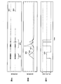
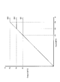
- FIG. 8 is a diagram illustrating an example of the state of each signal in the case where spontaneous speech noise is included.
- the passband cutoff frequency band of the low-pass filter of the first and second band signal extraction units 121-1 and 121-2 is 50 to 180 Hz
- the passband cutoff frequency band of the high-pass filter is 2000 to 3000 Hz.
- FIG. 8A shows waveforms of the first sound collection signal and the second sound collection signal.
- FIG. 8B shows waveforms of the low-frequency vibration component level signal and the high-frequency vibration component level signal and the first threshold value.
- FIG. 8C shows a change in the value of the identification result.
- the vibration component extraction unit 120 includes the first sound collection signal 613 and the second sound collection signal 613 including the speech of the other speaker (hereinafter referred to as “other speech”) 611 and the self-speech speech 612. Is input.
- the low-frequency vibration component level 615 (low_lev) is small on average in the section of the other utterance voice 611. At this time, the low-frequency vibration component level 615 (low_lev) does not exceed the first threshold value 617 (thr1).
- the high frequency vibration component level 616 is increased in a part of the section of the other utterance voice 611. This is because, for the high-frequency vibration component level 616 (high_lev), the correlation between the microphone outputs collapses due to the influence of the surrounding environment of the hearing aid and the influence of the phase difference.
- the low-frequency vibration component level 615 (low_lev) becomes large and exceeds the first threshold value 617 (thr1) in the section of the spontaneous speech 612. This is because the self-speech voice 612 includes a solid propagation sound due to bone conduction of the spoken voice.
- the high frequency vibration component level 616 (high_lev) is low in the section of the spontaneous speech 612. This is because the high frequency component of the spoken voice has less bone conduction than the low frequency component, and there are also few components in the voice, so that it is difficult to transmit to the microphone of the hearing aid as vibration.
- the band level ratio high_lev / low_lev is low and does not exceed the second threshold (thr2).
- FIG. 9 is a diagram illustrating an example of the state of each signal when contact vibration noise is included, and corresponds to FIG.
- the vibration component extraction unit 120 includes a first sound collection signal 623 and a second sound collection signal 623 including a self-speech voice 621 and contact vibration noise (here, a rubbing sound when the hearing aid 100 is removed) 622. Is input.
- both the low-frequency vibration component level 625 (low_lev) and the high-frequency vibration component level 626 (high_lev) are high. Therefore, the low-frequency vibration component level 625 (low_lev) exceeds the first threshold value 627 (thr1). Further, the band level ratio high_lev / low_lev becomes high and exceeds the second threshold value (thr2).
- the hearing aid 100 can accurately detect contact vibration noise from the collected sound signal.
- the hearing aid 100 extracts the uncorrelated component between the collected sound signals as the vibration component for each band, and identifies the noise based on the level of the high frequency band. Contact vibration noise can be detected.
- the hearing aid 100 Accordingly, the hearing aid 100 according to the present embodiment generates howling using the two sound collecting microphones 110 originally provided in the hearing aid 100 without providing a new sensor other than the microphone. Can be suppressed from.
- the hearing aid 100 can discriminate between the spontaneous speech noise and the contact vibration noise by analyzing the vibration component for each band.
- the hearing aid 100 can detect the self-speech noise from the collected sound signal, and can apply a relatively light suppression to the sound signal of the self-speech than at the time of howling detection. Adverse effects such as applying excessive suppression can be avoided.
- the hearing aid 100 may stop updating the correction multiplication value when the level of the low-frequency and high-frequency uncorrelated components exceeds a certain level. Thereby, the hearing aid 100 performs sensitivity correction only when a highly correlated air-propagating sound is input, and can extract a non-correlated component with higher accuracy.
- the hearing aid 100 may calculate a value obtained by taking the square root of the square value instead of the square value of the low-frequency signal and the high-frequency signal as the low-frequency signal and the high-frequency signal.
- vibration noise components (for each band) are extracted from each of a plurality of bands divided more finely than in the second embodiment, and the contact vibration noise is based on the spectrum pattern of the vibration noise components. It is an example of the hearing aid which detects. In the present embodiment, it is assumed that the hearing aid extracts vibration noise components for each of the predetermined divided bands of N (N is an integer of 3 or more) different center frequencies.
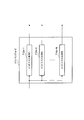
- FIG. 10 is a block diagram showing an example of the configuration of the hearing aid according to the present embodiment, and corresponds to FIG. 2 of the second embodiment. The same parts as those in FIG.
- the hearing aid 100a has a vibration component extraction unit 120a instead of the vibration component extraction unit 120 shown in FIG.
- the vibration component extraction unit 120a has a first band signal extraction unit 121a-1, a second band signal extraction unit 121a-2, and first to third bands corresponding to the above-described divided bands. Nth vibration component extraction units 122a-1 to 122a-N are included.
- the hearing aid 100a includes a vibration noise identification unit 130a instead of the vibration noise identification unit 130 shown in FIG.
- the first band signal extraction unit 121a-1 extracts a signal for each of the N divided bands described above from the first collected sound signal. Further, the first band signal extraction unit 121a-1 outputs the extracted signal to the first to Nth vibration component extraction units 122a-1 to 122a-N corresponding to the divided bands, respectively.
- the second band signal extraction unit 121a-2 extracts a signal for each of the N divided bands described above from the second collected sound signal. Further, the second band signal extraction unit 121a-2 outputs the extracted signal to the first to Nth vibration component extraction units 122a-1 to 122a-N corresponding to the divided bands, respectively.
- the first band signal extraction unit 121a-1 and the second band signal extraction unit 121a-2 have, for example, the same configuration and can use an N-divided filter bank or FFT.
- FIG. 11 is a block diagram showing an example of the configuration of first and second band signal extraction units 121a-1 and 121a-2 using an N-divided filter bank, and corresponds to FIG. 5 of the second embodiment. It is.
- the first and second band signal extraction units 121a-1 and 121a-2 include, for example, first to Nth bandpass filters 710a-1 to 710a corresponding to the above-described divided bands. -N.
- the first to Nth band-pass filters 710a-1 to 710a-N perform filtering on the collected sound signal with the corresponding divided bands as pass bands.
- FIG. 12 is a block diagram showing an example of the configuration of the first and second band signal extraction units 121a-1 and 121a-2 using FFT.
- the first and second band signal extraction units 121a-1 and 121a-2 include, for example, an analysis window unit 720a and an FFT unit 730a.
- the analysis window unit 720a applies an analysis window to the first collected sound signal.
- a window function for example, Hanning window
- a window function suitable for the purpose of extraction / identification in the subsequent stage is selected from the viewpoint of spectrum leak prevention and frequency resolution.
- the FFT unit 730a decomposes the output signal of the analysis window unit 720a into the above-described frequency spectrum for each divided band. That is, the FFT unit 730a converts a signal obtained by multiplying the analysis window from a time waveform to a frequency signal, and generates a complex frequency spectrum.
- the spectral resolution of the FFT unit 730a may be the number of divided bands (N) or a higher number. In the latter case, the FFT unit 730a may calculate a spectrum (spectrum bin) with high resolution and output information in which a plurality of spectrum bins are grouped (grouped) for each divided band. It is desirable that the grouping configuration of the spectrum bins is such that a difference in vibration components to be identified is likely to appear on the frequency axis. That is, it is desirable that the FFT unit 730a performs grouping for each band in which vibration components are likely to be generated.
- first band-specific signal the signal for each divided band output by the first band signal extraction unit 121a-1
- second band-specific signal the signal for each divided band output by the second band signal extraction unit 121a-2
- the first to Nth vibration component extraction units 122a-1 to 122a-N in FIG. 10 extract the vibration components of the corresponding divided bands from the first band-specific signals and the second band-specific signals respectively input thereto. Extract. Further, the first to Nth vibration component extraction units 122a-1 to 122a-N output a signal indicating the level of the extracted vibration component to the vibration noise identification unit 130. Note that the first to Nth vibration component extraction units 122a-1 to 122a-N are, for example, the low-frequency vibration component extraction unit 122-1 and the high-frequency vibration component extraction unit 122- shown in FIG. 2 and the same configuration.
- Each vibration component extraction unit 122a calculates the power spectrum using a complex spectrum when the first and second band signal extraction units 121a-1 and 121a-2 use FFT. And, when the values of a plurality of grouped spectrum bins are input as the band-specific signals, for example, each vibration component extraction unit 122a may take an average of those values (power spectrum).
- signals for each divided band output by the first to Nth vibration component extraction units 122a-1 to 122a-N are referred to as “band-based vibration component level signals”.
- the vibration noise identification unit 130a stores in advance, in a normalized state, the spectrum pattern of the vibration component of the self-speaking noise (hereinafter referred to as “self-speech template”) and the spectrum pattern of the vibration component of the contact vibration noise. .
- the spectrum pattern of the vibration component of the contact vibration noise is hereinafter referred to as “contact vibration template”.
- normalization of the spectrum pattern means that the maximum value of each divided band is 1, and for example, all the divided band values are divided by the aforementioned maximum value. Means.
- the vibration noise identification unit 130a obtains a spectrum pattern (hereinafter referred to as “detected noise pattern”) of the vibration component of the collected sound signal indicated by the first to Nth band-specific vibration component level signals. Then, the vibration noise identification unit 130a determines that the contact vibration noise has occurred on the condition that the detected noise pattern is more similar to the contact vibration template than the self-spoken template.
- FIG. 13 is a flowchart showing an example of the operation of the hearing aid 100a, and corresponds to FIG. 7 of the second embodiment.
- the same parts as those in FIG. 7 are denoted by the same reference numerals, and description thereof will be omitted.
- the first band signal extraction unit 121a-1 extracts a first band-specific signal for each divided band from the first sound collection signal.
- the second band signal extraction unit 121a-2 extracts a second band-specific signal for each divided band from the second sound collection signal.
- step S1400a the first to Nth vibration component extraction units 122a-1 to 122a-N perform the uncorrelated component between the first band-specific signal and the second band-specific signal for each divided band. Are extracted as vibration components.
- step S1500a the vibration noise identification unit 130a acquires the low-frequency vibration component level low_lev described in the second embodiment. For example, the vibration noise identification unit 130a calculates the average value of the band-specific vibration component level signals of all the divided regions included in the low frequency described in the second embodiment as the low frequency vibration component level low_lev.
- step S1600 the vibration noise identification unit 130 determines whether or not the low frequency vibration component level low_lev is equal to or higher than the first threshold value thr1.
- the vibration noise identifying unit 130 proceeds to step S1750a.
- step S1750a the vibration noise identification unit 130a normalizes the detection noise pattern indicated by the first to Nth band-specific vibration component level signals.
- vibration noise identification unit 130a determines whether the normalized detection noise pattern (hereinafter simply referred to as “detection noise pattern”) is more similar to the contact vibration template than the self-spoken template.
- the vibration noise identifying unit 130a quantifies the degree of similarity between the detected noise pattern and the self-spoken template and the degree of similarity between the detected noise pattern and the contact vibration template, and compares the degree of similarity. .
- the vibration noise identification unit 130a uses the mean square error as a value indicating the degree of similarity.
- the mean square error ⁇ m ( ⁇ 0, ⁇ 1) is calculated.
- the value of the detected noise pattern is set to xk
- the value of the mth template is set to ym, k.
- the vibration noise identification unit 130a compares the mean square error ⁇ 0 between the calculated self-speech template and the mean square error ⁇ 1 between the contact vibration template, and the detected noise pattern becomes smaller as the value is smaller. Judge that they are similar. That is, vibration noise identification unit 130a determines that the detected noise pattern is more similar to the contact vibration template than the spontaneous speech template if ⁇ 1> ⁇ 0.
- the vibration noise identification unit 130a proceeds to step S1900 when the detected noise pattern is not more similar to the contact vibration template than the spontaneous speech template (S1800a: NO). If the detected noise pattern is more similar to the contact vibration template than the self-utterance template (S1800a: YES), vibration noise identification unit 130 proceeds to step S2000.
- the hearing aid 100a can extract the vibration noise component from each of the many divided bands and detect the contact vibration noise based on the spectrum pattern of the vibration noise component.
- the hearing aid 100a can detect the contact vibration noise using the vibration noise component for each band extracted more finely than in the second embodiment.
- the hearing aid 100a is suitable, for example, when there are many fluctuations in the band level ratio depending on the surrounding environment and wearing state. That is, the hearing aid 100a can extract and identify vibrations with higher accuracy.
- the hearing aid 100a according to the present embodiment has more functional units than the case where the processing is performed for two divided bands as in the second embodiment, so that the hardware restriction for performing the signal processing becomes larger. There is a case. Therefore, the hearing aid 100a according to the present embodiment is suitable for situations where there are fewer hardware restrictions on signal processing than in the second embodiment, and particularly when highly accurate vibration noise identification is required.
- the fourth embodiment of the present invention is an example in which an audio limiter is applied to the suppression processing unit of the second embodiment.
- FIG. 14 is a block diagram showing an example of the configuration of the hearing aid according to the present embodiment, and corresponds to FIG. 2 of the second embodiment. The same parts as those in FIG.
- the hearing aid 100b has an acoustic signal processing unit 140b instead of the acoustic signal processing unit 140 of FIG.
- the acoustic signal processing unit 140b includes an audio limiter 142b as a specific example of the suppression processing unit 142 in FIG.
- the audio limiter 142b as the predetermined process for suppressing the above-described howling, suppresses the sound volume so that the sound signal does not exceed a set output level while the identification result is “with contact vibration noise”. I do. That is, the audio limiter 142b performs a process of adaptively lowering (limiting) the volume so that the volume does not reach a certain level.
- the audio limiter 142b changes its limiter parameter every time the state of vibration noise changes.
- Limiter parameters include limiter point and release time.
- the limiter point is a target value for suppressing the output level. The lower the limit point, the smaller the volume of the acoustic signal.
- the release time is the length of time until the suppression of the output level is released (returned). The longer the release time, the longer the state in which the volume of the acoustic signal is suppressed.
- the audio limiter 142b holds a set of the limiter point P1 and the release time t1 corresponding to the identification result “contact vibration noise exists”.
- the audio limiter 142b holds a set of the limiter point P2 and the release time t2 corresponding to the identification result “speech noise is present”.
- the audio limiter 142b holds a set of the limiter point P3 and the release time t3 corresponding to the identification result “no vibration noise”.
- release time t3 is a default value and an upper limit value of the release time.
- the limiter point P3 is a default value and a lower limit value of the limiter point.
- FIG. 15 is a diagram illustrating an example of input / output characteristics of the audio limiter 142b.
- the horizontal axis indicates the level (volume level) of the input signal to the audio limiter 142b
- the vertical axis indicates the level (volume level) of the output signal from the audio limiter 142b.
- the first to third input / output characteristics 631 to 633 correspond to the limiter points P1 to P3 in this order.
- the limiter points P1 to P3 have, for example, the relationship shown in Expression (3).
- the audio limiter 142b switches to the corresponding limiter parameter according to the input identification result.
- the audio limiter 142b does not particularly reduce the volume of the acoustic signal, and immediately cancels even if the volume is reduced.
- the audio limiter 142b lowers the limiter point a little to reduce the volume of the sound signal, but releases it in a relatively short time.
- the audio limiter 142b lowers the limiter point as much as possible to reduce the volume of the acoustic signal, and slowly releases it.
- the hearing aid 100b when the hearing aid 100b is detached, howling is likely to occur as described above. Therefore, the hearing aid 100b can make acoustic oscillation (howling) between the audio receiver 150 and the microphone 110 as difficult as possible by switching the limiter parameter.
- the hearing aid 100b may make it difficult to hear the self-speaking voice when listening to other voices, for example. Therefore, the hearing aid 100b can collect and expand the sound by suppressing the occurrence of the head loss of the other speaker while suppressing the self-speech voice by the above-described limiter parameter switching.
- the operation of the hearing aid 100b differs only in step 2200 in the flowchart shown in FIG. 7 of the second embodiment. Therefore, the process (that is, the volume suppression process) executed by the hearing aid 100b in step S2200 in FIG. 7 will be described.
- FIG. 16 is a flowchart showing an example of a volume suppression process executed by the hearing aid 100b.
- step S2210b the audio limiter 142b determines whether or not the identification result is “no vibration noise”.
- the audio limiter 142b proceeds to step S2220b. If the identification result is not “no vibration noise” (S2210b: NO), the audio limiter 142b proceeds to step S2230b.
- step S2220b the audio limiter 142b changes the limiter parameter to the limiter parameter (limiter point P3, release time t3) corresponding to “no vibration noise”, and returns to the process of FIG.
- the audio limiter 142b maintains the setting. Further, when the limiter parameter is changed to a value corresponding to “no vibration noise”, the audio limiter 142b desirably uses an integrator or the like to gradually change the limiter point and the release time. Thereby, the hearing aid 100b of this Embodiment can naturally perform the loudness of the surrounding sound to the ear hole.
- step S2230b the audio limiter 142b determines whether or not the identification result is “with spontaneous speech noise”.
- the audio limiter 142b proceeds to Step S2240b when the identification result is “with spontaneous speech noise” (S2230b: YES). Further, if the identification result is not “with spontaneous speech noise”, that is, if the identification result is “with contact vibration noise” (S2230b: NO), the audio limiter 142b proceeds to step S2250b.
- step S2240b the audio limiter 142b changes the limiter parameter to the limiter parameter (limiter point P2, release time t2) corresponding to “with spontaneous speech noise”, and returns to the process of FIG. Note that the audio limiter 142b maintains the setting when the limiter parameter corresponding to “with spontaneous speech noise” is already set.
- step S2250b the audio limiter 142b changes the limiter parameter to the limiter parameter (limiter point P1, release time t1) corresponding to “with contact vibration noise”, and returns to the process of FIG. If the limiter parameter corresponding to “contact vibration noise exists” is already set, the audio limiter 142b maintains the setting.
- the state of the hearing aid 100b changes mainly when it is attached and immediately after it, during use, when it is removed, and immediately after that.
- the hearing aid 100b is judged to be “contact vibration noise” due to contact with a hand or ear immediately after wearing, the limiter is applied relatively strongly.
- the limiter is relatively lightly applied.
- the hearing aid 100b places a limiter on a moderate level to determine that there is “self-uttering noise”.
- the hearing aid 100b is subjected to a relatively strong limiter again to determine that there is “contact vibration noise” by contact with the hand or ear immediately after removal.
- the hearing aid 100b can suppress howling without impairing usability as much as possible.
- the hearing aid 100b introduces the audio limiter 142b that controls the output level restriction on the hearing aid processing output (acoustic signal) of the hearing aid processing unit 141.
- the hearing aid 100b according to the present embodiment can perform volume control according to the identification result of the vibration noise. That is, the hearing aid 100b according to the present embodiment can be used as usual when vibration noise is not detected, and the volume can be suppressed when contact vibration noise is detected.
- the hearing aid 100b can suppress the spontaneous speech while preventing the other speaker's head from being cut off when the spontaneous speech noise is detected.
- the hearing aid 100b may set the release time at the time of removal longer (eg, t1) than the release time at the time of wearing. As a result, the hearing aid 100b takes a long time to suppress the volume, so that the power can be turned off with a margin before howling occurs.
- Whether it is at the time of attachment or removal can be determined from the length of contact vibration noise, for example. This is because, in the ear-mounted hearing aid 100b, the eartip 330 is attached to the ear hole by groping, so that the duration of vibration noise is usually longer when worn than when removed.
- the audio limiter 142b of the hearing aid 100b may be applied to a hearing aid that identifies vibration noise based on vibration noise components extracted from three or more frequency bands as in the third embodiment.
- the audio limiter is arranged at the subsequent stage of the hearing aid processing unit for the sake of simplicity that only one system can be applied to the limiter.
- the audio limiter is arranged at the preceding stage of the hearing aid processing. May be. In this case, it is possible to individually perform suppression processing on the first sound collection signal and the second sound collection signal.
- the fifth embodiment of the present invention is an example in which a howling canceller is applied to the suppression processing unit of the second embodiment.
- FIG. 17 is a block diagram showing an example of the configuration of a hearing aid according to Embodiment 5 of the present invention, and corresponds to FIG. 2 of Embodiment 2. The same parts as those in FIG.
- the hearing aid 100c has an acoustic signal processing unit 140c instead of the acoustic signal processing unit 140 of FIG.
- the acoustic signal processing unit 140c includes a howling canceller 142c arranged in front of the hearing aid processing unit 141 as a specific example of the suppression processing unit 142 in FIG.
- the howling canceller 142c performs a howling sound volume suppression process by subtracting a pseudo howling signal from each of the first and second collected sound signals as the predetermined process for suppressing the above-described howling.
- the pseudo howling signal is a signal simulating a howling signal generated between the receiver 150 and the microphone 110.
- the howling canceller 142c generates this pseudo howling signal based on the hearing aid processing output (acoustic signal) output from the hearing aid processing unit 141.
- the howling canceller 142c outputs the first and second collected sound signals subjected to howling sound volume suppression processing to the hearing aid processing unit 141.
- FIG. 18 is a block diagram showing an example of the configuration of the howling canceller 142c.
- the howling canceller 142c has, for example, two systems, a first sound collection signal system and a second sound collection signal system. Since these two systems have the same configuration, only the configuration of one system is shown and described. FIG. 18 also shows the surrounding functional units for convenience of description.
- the howling canceller 142c includes a delay operation unit 810c, an adder 820c, an adaptive filter 830c, a coefficient update control unit 840c, and a howling detection unit 850c.
- the delay operation unit 810c outputs a signal obtained by delaying the hearing aid processing output (acoustic signal) output from the hearing aid processing unit 141 to the adaptive filter and coefficient update control unit 840c as a delayed hearing aid processing output.
- the adder 820c outputs a signal indicating a difference between the collected sound signal of the microphone 110 and the pseudo howling signal of the adaptive filter 830c as a howling canceller output signal to the hearing aid processing unit 140 and the coefficient update control unit 840c.
- the adaptive filter 830c outputs a signal obtained by filtering the delayed hearing aid processing output of the delay operation unit 810c using the filter coefficient output from the coefficient update control unit 840c to the adder 820c as a pseudo howling signal.
- the coefficient update control unit 840c acquires the delay hearing aid processing output of the delay operation unit 810c, the howling canceller output of the adder 820c, the identification result of the vibration noise identification unit 130, and the howling detection signal of the howling detection unit 850c.
- the coefficient update control unit 840c updates the filter coefficient of the adaptive filter 830c using the delayed hearing aid processing output, the howling canceller output, the identification result, and the howling detection signal.
- the filter coefficient is updated at a speed corresponding to the step gain ⁇ (0 ⁇ ⁇ 1) set by the coefficient update control unit 840c.
- the coefficient update control unit 840c controls parameters related to the filter coefficient update process according to whether or not contact vibration noise is generated.
- the coefficient update rate of the adaptive filter is controlled.
- the howling detection unit 850c monitors the collected sound signal of the microphone 110, detects the howling waveform, and outputs the detection result to the coefficient update control unit 840c.
- step S2200 of FIG. 7 The operation of the hearing aid 100c is different only in step 2200 in the flowchart shown in FIG. Therefore, processing (that is, volume suppression processing) executed by the hearing aid 100c in step S2200 of FIG. 7 will be described.
- FIG. 19 is a flowchart showing an example of a volume suppression process executed by the hearing aid 100c.
- step S2210c howling canceller 142c determines whether or not the identification result is “there is contact vibration noise”.
- the howling canceller 142c proceeds to step S2220c when the identification result is “with contact vibration noise” (S2210c: YES). If the identification result is not “contact vibration noise present” (S2210c: NO), howling canceller 142c proceeds to step S2230c.
- step S2220c howling canceller 142c gradually increases or maintains step gain ⁇ of filter coefficient to maximum value ⁇ h of step gain that is higher than default value ⁇ d of step gain ⁇ . That is, howling canceller 142c updates filter coefficients at high speed.
- the coefficient update control unit 840c of the howling canceller 142c updates the step gain ⁇ so as to gradually approach the maximum value ⁇ h using, for example, the following equation (4).
- n represents the current time
- ⁇ is a fixed value sufficiently smaller than 1. That is, ⁇ (n) is a step gain to be set at present, and ⁇ (n ⁇ 1) is a step gain set at the previous time.
- ⁇ var is a variable for storing a target value (here, maximum value ⁇ h) of the step gain ⁇ .
- step S2230c howling canceller 142c gradually decreases or maintains step gain ⁇ var of filter coefficient update to default value ⁇ d of step gain ⁇ var or maintains default value ⁇ d. That is, the howling canceller 142c updates the filter coefficient at a normal speed.
- the coefficient update control unit 840c of the howling canceller 142c uses, for example, the above equation (4) in which the default value ⁇ d is stored in ⁇ var so that the step gain ⁇ var gradually approaches the default value ⁇ d. Update.
- step S2240c howling canceller 142c performs howling cancellation processing for suppressing howling components in the first and second collected sound signals and obtaining howling cancellation output.
- the howling canceller 142c applies a delay that satisfies the causality by the delay operation unit 810c to the acoustic signal after the hearing aid processing. Thereafter, howling canceller 142c performs filter processing by adaptive filter 830c to generate a pseudo howling signal.
- howling canceller 142c uses adder 820c to calculate the difference between each of the first and second collected sound signals from the pseudo howling signal, and outputs an acoustic signal in which howling has been canceled.
- the howling canceller 142c updates the filter coefficient of the adaptive filter 830c with the set step gain using, for example, NLMS (learning identification method).
- howling canceller 142c updates coefficient vector w of the coefficient of the adaptive filter using, for example, the following equation (5).
- x is an output signal vector of the howling canceller
- e is a canceller output sample
- ⁇ is a small coefficient for preventing the denominator from becoming zero.
- the step gain ⁇ becomes a high value when contact vibration noise is detected, and as a result, the convergence speed of the coefficient vector increases.
- the pseudo howling signal can quickly follow the sudden fluctuation of the acoustic system. Therefore, the howling canceller 142c can effectively suppress (cancel) the occurrence of howling due to the fluctuation of the acoustic system when the hearing aid 100c is attached / detached by the above-described step gain control and howling cancellation processing.
- the hearing aid 100c can perform the above-described howling suppression while suppressing the influence on the original acoustic signal to a minimum.
- the howling canceller 142c returns to the processing of FIG. 7 after completing the howling cancellation processing.
- the hearing aid 100c introduces the howling canceller 142c that performs the howling cancellation process on the hearing aid processing output (acoustic signal) of the hearing aid processing unit 141.
- the hearing aid 100c according to the present embodiment can perform howling cancellation processing according to the identification result of the vibration noise. That is, the hearing aid 100c according to the present embodiment can be used as usual when the contact vibration noise is not detected, and can effectively suppress howling when the contact vibration noise is detected. In other words, the hearing aid 100c according to the present embodiment can quickly follow the howling at the time of attachment / detachment.
- the hearing aid 100c can realize howling canceller processing that can provide a stable volume suppression amount when the fluctuation of the acoustic system is reduced.
- contact vibration noise is detected and the coefficient updating unit parameter of the adaptive filter is controlled.
- application of the detection result is not limited to this.
- the detection of contact vibration noise may be used for suppression processing such as lowering the gain of the microphone 110-1 (110-2), and can be applied to various parameter control for controlling howling.
- the hearing aid 100c uses the vibration noise duration time to determine whether it is attached or attached, and sets the step gain higher when attached than when it is attached. The control speed for reducing the gain may be reduced. Thereby, the hearing aid 100c can ensure the stability after wearing, suppressing the howling produced immediately after removing from the ear most effectively.
- control using the spontaneously detected spontaneous speech noise is not particularly described, but the fourth embodiment is not described. You may use this as well.
- the hearing aid it is desirable for the hearing aid to control the sound volume so that the suppression and return operations in the suppression control can be performed quickly compared to howling suppression when detecting contact vibration noise.
- the hearing aid can suppress the volume adjustment to such an extent that it does not become annoying, and can prevent the other speaker from being cut off.
- the binaural hearing aid may perform howling suppression processing in synchronization with other hearing aids mounted on the opposite ear of both ears.
- a hearing aid for binaural ears detects vibration noise
- at least one of the two hearing aids for both ears not only the hearing aid but also the other hearing aid has a predetermined process corresponding to the detection of the vibration noise. May start.
- the hearing aid needs to further include a communication unit that communicates with other hearing aids.
- the vibration noise identification unit determines that at least the contact vibration noise has occurred, it needs to transmit information indicating the fact to the other hearing aid using the communication unit.
- the acoustic signal control unit receives information indicating that contact vibration noise has been generated from another hearing aid, it receives this using the communication unit and generates contact vibration noise in its own device. It is necessary to perform the same processing as when it was determined that the
- the user In the case of a binaural hearing aid, the user usually wears the other immediately after wearing one. Therefore, the hearing aid to be mounted later can avoid the occurrence of howling in advance and prevent the occurrence of howling more reliably. Moreover, such a hearing aid can relieve the sense of incongruity due to the difference between the left and right hearing after wearing.
- the predetermined process according to whether or not the contact vibration noise is generated is a process for suppressing howling, but is not limited thereto.
- the application of the vibration detection method of the present invention is not limited to a hearing aid.
- various kinds of sound including a loudspeaker and a plurality of microphones for collecting sound are provided. It can be applied to equipment.
- the hearing aid and the vibration detection method according to the present invention are useful as a hearing aid and a vibration detection method capable of detecting contact vibration noise from a collected sound signal.
- 100, 100a, 100b, 100c Hearing aid 110-1, 110-2 Microphone 120, 120a Vibration component extraction unit 121-1, 121a-1 First band signal extraction unit 121-1, 121a-2 Second band signal extraction Unit 122-1 low-frequency vibration component extraction unit 122-2 high-frequency vibration component extraction unit 122a-1 to 122a-N first to Nth vibration component extraction units 130, 130a vibration noise identification units 140, 140b, 140c acoustic signal Processing unit 141 Hearing aid processing unit 142 Suppression processing unit 142b Audio limiter 142c Howling canceller 150 Receiver 160 Output unit 310 Hearing aid body 320 Acoustic tube 330 Ear chip 410-1 Low-pass filter 410-2 High-pass filter 510-1 First square value calculation Part 510-2 second square value calculation part 520 -1 First smoothing unit 520-2 Second smoothing unit 530 Variable multiplier 540 Adder 550 Absolute value calculation unit 710a-1 to 710a-N First to Nth band pass filters 720a Analysis window unit 730a FFT unit 810
Abstract
Description
本発明の実施の形態1に係る補聴器は、ユーザの左右いずれかの耳に装着し、収音と、所定の処理を行った音声を拡声して装用者の耳穴内への出力とを行う、耳掛け型の補聴器に適用した例である。以下に説明する音響処理装置の各部は、例えば、補聴器の内部に配置されたマイクロホン、レシーバ、およびCPU(central processing unit)、制御プログラムを格納したROM(read only memory)などの記憶媒体を含むハードウェアにより実現される。
本発明の実施の形態2に係る補聴器は、補聴処理とハウリング抑制のための処理とを行う、耳掛け型の補聴器に適用した例である。
本発明の実施の形態3は、実施の形態2よりもより細かに分割した複数の帯域のそれぞれから(帯域別の)振動ノイズ成分を抽出し、振動ノイズ成分のスペクトルパターンに基づいて接触振動ノイズを検出する補聴器の例である。本実施の形態において、補聴器は、予め定められた、N個(Nは3以上の整数)の中心周波数の異なる分割帯域ごとに、振動ノイズ成分を抽出するものとする。
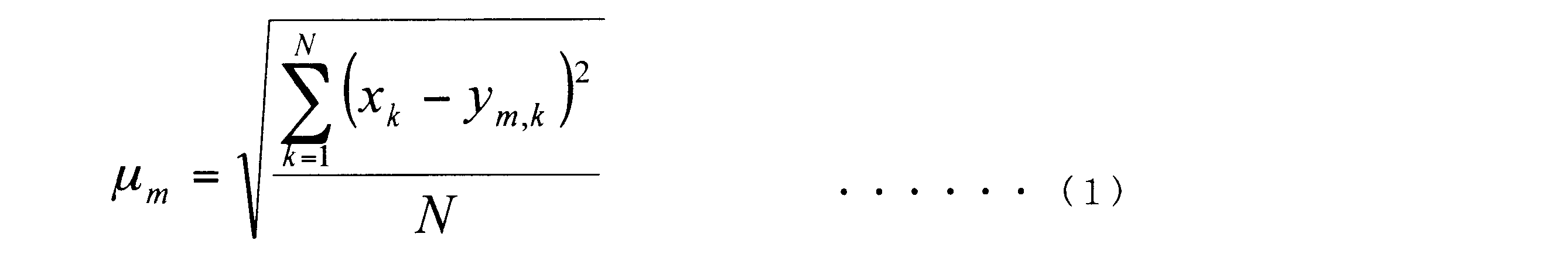
本発明の実施の形態4は、実施の形態2の抑制処理部にオーディオリミッタを適用した例である。
t3<t2<t1 ・・・・・・(2)
P1<P2<P3 ・・・・・・(3)
本発明の実施の形態5は、実施の形態2の抑制処理部にハウリングキャンセラを適用した例である。

110-1、110-2 マイクロホン
120、120a 振動成分抽出部
121-1、121a-1 第1の帯域信号抽出部
121-1、121a-2 第2の帯域信号抽出部
122-1 低域振動成分抽出部
122-2 高域振動成分抽出部
122a-1~122a-N 第1~第Nの振動成分抽出部
130、130a 振動ノイズ識別部
140、140b、140c 音響信号処理部
141 補聴処理部
142 抑制処理部
142b オーディオリミッタ
142c ハウリングキャンセラ
150 レシーバ
160 出力部
310 補聴器本体
320 音響管
330 イヤチップ
410-1 低域フィルタ
410-2 高域フィルタ
510-1 第1の二乗値算出部
510-2 第2の二乗値算出部
520-1 第1の平滑化部
520-2 第2の平滑化部
530 可変乗算器
540 加算器
550 絶対値算出部
710a-1~710a-N 第1~第Nのバンドパスフィルタ
720a 分析窓部
730a FFT部
810c 遅延操作部
820c 加算器
830c 適応フィルタ
840c 係数更新制御部
850c ハウリング検知部
Claims (10)
- 2つのマイクロホンと、
前記2つのマイクロホンがそれぞれ取得した収音信号から、前記2つの収音信号間の無相関成分を、帯域別に振動成分として抽出する振動成分抽出部と、
前記振動成分抽出部で抽出された前記帯域別の振動成分に基づいて、接触振動ノイズが発生したか否かを判断する振動ノイズ識別部と、
前記2つの収音信号を補聴処理して音響信号を生成する際に、前記音響信号に対して、前記接触振動ノイズの発生の有無に応じた処理を行う音響信号処理部と、
前記音響信号を音に変換するレシーバと、を有する、
補聴器。 - 前記振動ノイズ識別部は、
前記帯域別の振動成分のうち、低周波数帯域の振動成分のみが検出された場合、当該振動成分を、自発話ノイズとして、接触振動ノイズと区別する、
請求項1記載の補聴器。 - 前記振動ノイズ識別部は、
前記振動成分の低周波数帯域のレベルに対して、前記振動成分の高周波数帯域のレベルが相対的に大きいことを条件として、接触振動ノイズが発生したと判断する、
請求項1記載の補聴器。 - 前記振動成分抽出部は、
前記2つの収音信号のそれぞれから、前記低周波数帯域の信号および前記高周波数帯域の信号を抽出する帯域信号抽出部と、
前記2つの低周波数帯域の信号から、前記振動成分の低周波数帯域のレベルを抽出し、前記2つの高周波数帯域の信号から、前記振動成分の高周波数帯域のレベルを抽出する、
請求項1記載の補聴器。 - 前記振動ノイズ識別部は、
前記振動成分の低周波数帯域のレベルに対する前記振動成分の高周波数帯域のレベルの比が所定の閾値を超えていることを条件として、前記接触振動ノイズが発生したと判断する、
請求項4記載の補聴器。 - 前記振動ノイズ識別部は、
前記振動成分のスペクトルパターンが、自発話ノイズの振動成分のスペクトルパターンよりも、前記接触振動ノイズの振動成分のスペクトルパターンに似ていることを条件として、前記接触振動ノイズが発生したと判断する、
請求項2記載の補聴器。 - 前記振動ノイズ識別処理部は、
前記振動成分が大きく、かつ、前記接触振動ノイズが発生していないことを条件として、自発話振動ノイズが発生したと判断し、
前記音響信号処理部は、
前記接触振動ノイズの発生の有無、および、前記自発話振動ノイズの発生の有無に応じて、前記音響信号の音量を制御するオーディオリミッタを含む、
請求項2記載の補聴器。 - 前記音響信号処理部は、
適応フィルタを用いて前記音響信号のハウリングの抑制を行い、前記接触振動ノイズの発生の有無に応じて、ハウリング抑圧に関係するパラメータを制御するハウリングキャンセラを含む、
請求項2記載の補聴器。 - 両耳のうち反対側の耳に装着された他の補聴器と通信を行う通信部、を更に有し、
前記振動ノイズ識別部は、
前記接触振動ノイズが発生したと判断したとき、その旨を示す情報を、前記通信部を用いて前記他の補聴器へ送信し、
前記音響信号処理部は、
前記他の補聴器から接触振動ノイズが発生したと判断した旨を示す情報が送信されてきたとき、前記通信部を用いてこれを受信し、
前記振動ノイズ識別部は、
前記接触振動ノイズが発生したと判断したときと同一の処理を行う、
請求項2記載の補聴器。 - 2つのマイクロホンを備えた補聴器における振動検出方法であって、
前記2つのマイクロホンがそれぞれ取得した収音信号から、前記2つの収音信号間の無相関成分を、帯域別に振動成分として抽出するステップと、
抽出された前記帯域別の振動成分に基づいて、接触振動ノイズが発生したか否かを判断するステップと、
前記2つの収音信号を補聴処理して音響信号を生成する際に、前記音響信号に対して、前記接触振動ノイズの発生の有無に応じた処理を行うステップと、を有する、
振動検出方法。
Priority Applications (3)
| Application Number | Priority Date | Filing Date | Title |
|---|---|---|---|
| JP2013509743A JP5938682B2 (ja) | 2011-04-11 | 2012-02-21 | 補聴器および振動検出方法 |
| CN2012800019651A CN102986252A (zh) | 2011-04-11 | 2012-02-21 | 助听器及振动检测方法 |
| US13/819,349 US9560456B2 (en) | 2011-04-11 | 2012-02-21 | Hearing aid and method of detecting vibration |
Applications Claiming Priority (2)
| Application Number | Priority Date | Filing Date | Title |
|---|---|---|---|
| JP2011087399 | 2011-04-11 | ||
| JP2011-087399 | 2011-04-11 |
Publications (1)
| Publication Number | Publication Date |
|---|---|
| WO2012140818A1 true WO2012140818A1 (ja) | 2012-10-18 |
Family
ID=47009016
Family Applications (1)
| Application Number | Title | Priority Date | Filing Date |
|---|---|---|---|
| PCT/JP2012/001157 WO2012140818A1 (ja) | 2011-04-11 | 2012-02-21 | 補聴器および振動検出方法 |
Country Status (4)
| Country | Link |
|---|---|
| US (1) | US9560456B2 (ja) |
| JP (1) | JP5938682B2 (ja) |
| CN (1) | CN102986252A (ja) |
| WO (1) | WO2012140818A1 (ja) |
Cited By (6)
| Publication number | Priority date | Publication date | Assignee | Title |
|---|---|---|---|---|
| WO2014027605A1 (ja) * | 2012-08-13 | 2014-02-20 | 株式会社レーベン販売 | 擦れ音防止補聴器 |
| US20140288357A1 (en) * | 2013-03-15 | 2014-09-25 | Martin Hillbratt | Filtering well-defined feedback from a hard-coupled vibrating transducer |
| JPWO2017042875A1 (ja) * | 2015-09-08 | 2018-07-19 | パイオニア株式会社 | 電子聴診装置、制御方法、コンピュータプログラム及び記録媒体 |
| JP2019519152A (ja) * | 2016-05-18 | 2019-07-04 | ボーズ・コーポレーションBose Corporation | 個人用音響装置のオン/オフヘッド検出 |
| WO2021230067A1 (ja) * | 2020-05-11 | 2021-11-18 | ソニーグループ株式会社 | 情報処理装置および情報処理方法 |
| JP2021183201A (ja) * | 2020-02-27 | 2021-12-02 | パイオニア株式会社 | 電子聴診装置、制御方法、コンピュータプログラム及び記録媒体 |
Families Citing this family (13)
| Publication number | Priority date | Publication date | Assignee | Title |
|---|---|---|---|---|
| CN102411936B (zh) * | 2010-11-25 | 2012-11-14 | 歌尔声学股份有限公司 | 语音增强方法、装置及头戴式降噪通信耳机 |
| US9685171B1 (en) * | 2012-11-20 | 2017-06-20 | Amazon Technologies, Inc. | Multiple-stage adaptive filtering of audio signals |
| US10257619B2 (en) * | 2014-03-05 | 2019-04-09 | Cochlear Limited | Own voice body conducted noise management |
| CN106303878A (zh) * | 2015-05-22 | 2017-01-04 | 成都鼎桥通信技术有限公司 | 一种啸叫检测和抑制方法 |
| CN106488052A (zh) * | 2015-08-27 | 2017-03-08 | 成都鼎桥通信技术有限公司 | 一种啸叫场景识别方法及设备 |
| KR20170055329A (ko) * | 2015-11-11 | 2017-05-19 | 삼성전자주식회사 | 노이즈를 제거하는 방법 및 이를 위한 전자 장치 |
| CN106768261B (zh) * | 2016-12-20 | 2023-10-13 | 歌尔科技有限公司 | 一种智能穿戴产品性能的测试装置和方法 |
| TWI633795B (zh) * | 2017-01-23 | 2018-08-21 | 芯籟半導體股份有限公司 | 一種訊號處理系統及其方法 |
| JP6809936B2 (ja) * | 2017-02-28 | 2021-01-06 | パナソニック インテレクチュアル プロパティ コーポレーション オブ アメリカPanasonic Intellectual Property Corporation of America | 雑音抽出装置およびマイクロホン装置 |
| DE102018209720B3 (de) * | 2018-06-15 | 2019-07-04 | Sivantos Pte. Ltd. | Verfahren zur Identifikation eines Hörers, Hörsystem und Hörerset |
| JP7270140B2 (ja) * | 2019-09-30 | 2023-05-10 | パナソニックIpマネジメント株式会社 | 音声処理システム及び音声処理装置 |
| CN114339569B (zh) * | 2020-08-29 | 2023-05-26 | 深圳市韶音科技有限公司 | 一种获取振动传递函数的方法和系统 |
| DE102021211879A1 (de) | 2021-10-21 | 2023-04-27 | Sivantos Pte. Ltd. | Hörgerät und Verfahren zum Betrieb eines solchen |
Citations (8)
| Publication number | Priority date | Publication date | Assignee | Title |
|---|---|---|---|---|
| JPH08163700A (ja) | 1994-12-08 | 1996-06-21 | Yamaha Corp | 補聴器 |
| JP2009105527A (ja) | 2007-10-22 | 2009-05-14 | Baisera:Kk | ハウリングの防止装置、防止方法、プログラム、及びこのプログラムを記録した記録媒体 |
| JP2009532924A (ja) * | 2006-04-01 | 2009-09-10 | ヴェーデクス・アクティーセルスカプ | 補聴器,および補聴器のためのアンチ・フィードバック・システムにおける適応速度の制御方法 |
| WO2009156906A1 (en) * | 2008-06-25 | 2009-12-30 | Koninklijke Philips Electronics N.V. | Audio processing |
| WO2010004769A1 (ja) * | 2008-07-11 | 2010-01-14 | パナソニック株式会社 | 補聴装置 |
| JP2010154432A (ja) * | 2008-12-26 | 2010-07-08 | Panasonic Corp | 補聴器 |
| JP2011087399A (ja) | 2009-10-15 | 2011-04-28 | Fuji Electric Systems Co Ltd | 電動機の巻線切替え装置 |
| JP2011139462A (ja) * | 2009-12-29 | 2011-07-14 | Gn Resound As | 補聴器におけるビームフォーミング |
Family Cites Families (5)
| Publication number | Priority date | Publication date | Assignee | Title |
|---|---|---|---|---|
| JPH0495500A (ja) * | 1990-08-10 | 1992-03-27 | Nippon Telegr & Teleph Corp <Ntt> | 補聴器 |
| JP2870421B2 (ja) | 1994-10-14 | 1999-03-17 | ヤマハ株式会社 | 話速変換機能を有する補聴器 |
| DK1673964T3 (en) * | 2003-10-10 | 2017-01-16 | Oticon As | METHOD OF TREATING THE SIGNALS FROM TWO OR MORE MICROPHONES IN A LISTENING AND LISTENING MULTIPLE MICROPHONES |
| WO2009044562A1 (ja) | 2007-10-04 | 2009-04-09 | Panasonic Corporation | マイクロホンを用いた雑音抽出装置 |
| EP2541971B1 (en) * | 2010-02-24 | 2020-08-12 | Panasonic Intellectual Property Management Co., Ltd. | Sound processing device and sound processing method |
-
2012
- 2012-02-21 CN CN2012800019651A patent/CN102986252A/zh active Pending
- 2012-02-21 WO PCT/JP2012/001157 patent/WO2012140818A1/ja active Application Filing
- 2012-02-21 JP JP2013509743A patent/JP5938682B2/ja active Active
- 2012-02-21 US US13/819,349 patent/US9560456B2/en active Active
Patent Citations (8)
| Publication number | Priority date | Publication date | Assignee | Title |
|---|---|---|---|---|
| JPH08163700A (ja) | 1994-12-08 | 1996-06-21 | Yamaha Corp | 補聴器 |
| JP2009532924A (ja) * | 2006-04-01 | 2009-09-10 | ヴェーデクス・アクティーセルスカプ | 補聴器,および補聴器のためのアンチ・フィードバック・システムにおける適応速度の制御方法 |
| JP2009105527A (ja) | 2007-10-22 | 2009-05-14 | Baisera:Kk | ハウリングの防止装置、防止方法、プログラム、及びこのプログラムを記録した記録媒体 |
| WO2009156906A1 (en) * | 2008-06-25 | 2009-12-30 | Koninklijke Philips Electronics N.V. | Audio processing |
| WO2010004769A1 (ja) * | 2008-07-11 | 2010-01-14 | パナソニック株式会社 | 補聴装置 |
| JP2010154432A (ja) * | 2008-12-26 | 2010-07-08 | Panasonic Corp | 補聴器 |
| JP2011087399A (ja) | 2009-10-15 | 2011-04-28 | Fuji Electric Systems Co Ltd | 電動機の巻線切替え装置 |
| JP2011139462A (ja) * | 2009-12-29 | 2011-07-14 | Gn Resound As | 補聴器におけるビームフォーミング |
Cited By (8)
| Publication number | Priority date | Publication date | Assignee | Title |
|---|---|---|---|---|
| WO2014027605A1 (ja) * | 2012-08-13 | 2014-02-20 | 株式会社レーベン販売 | 擦れ音防止補聴器 |
| US20140288357A1 (en) * | 2013-03-15 | 2014-09-25 | Martin Hillbratt | Filtering well-defined feedback from a hard-coupled vibrating transducer |
| US10812919B2 (en) * | 2013-03-15 | 2020-10-20 | Cochlear Limited | Filtering well-defined feedback from a hard-coupled vibrating transducer |
| JPWO2017042875A1 (ja) * | 2015-09-08 | 2018-07-19 | パイオニア株式会社 | 電子聴診装置、制御方法、コンピュータプログラム及び記録媒体 |
| JP2019519152A (ja) * | 2016-05-18 | 2019-07-04 | ボーズ・コーポレーションBose Corporation | 個人用音響装置のオン/オフヘッド検出 |
| JP2021183201A (ja) * | 2020-02-27 | 2021-12-02 | パイオニア株式会社 | 電子聴診装置、制御方法、コンピュータプログラム及び記録媒体 |
| JP7357031B2 (ja) | 2020-02-27 | 2023-10-12 | エア・ウォーター・バイオデザイン株式会社 | 電子聴診装置及び制御方法 |
| WO2021230067A1 (ja) * | 2020-05-11 | 2021-11-18 | ソニーグループ株式会社 | 情報処理装置および情報処理方法 |
Also Published As
| Publication number | Publication date |
|---|---|
| JPWO2012140818A1 (ja) | 2014-07-28 |
| CN102986252A (zh) | 2013-03-20 |
| JP5938682B2 (ja) | 2016-06-22 |
| US9560456B2 (en) | 2017-01-31 |
| US20130156208A1 (en) | 2013-06-20 |
Similar Documents
| Publication | Publication Date | Title |
|---|---|---|
| JP5938682B2 (ja) | 補聴器および振動検出方法 | |
| US10657950B2 (en) | Headphone transparency, occlusion effect mitigation and wind noise detection | |
| KR102512311B1 (ko) | 이어버드 스피치 추정 | |
| JP6215488B2 (ja) | 能動騒音低減イヤホン、該イヤホンに適用する騒音低減制御方法及びシステム | |
| US9094749B2 (en) | Head-mounted sound capture device | |
| US10861484B2 (en) | Methods and systems for speech detection | |
| US11363389B2 (en) | Hearing device comprising a beamformer filtering unit for reducing feedback | |
| CN112334972A (zh) | 反馈不稳定性的实时检测 | |
| TW200834541A (en) | Ambient noise reduction system | |
| JP2019519819A (ja) | 能動型ノイズ制御システムにおける不安定状態の緩和 | |
| CN113711308A (zh) | 风噪声检测系统和方法 | |
| JP2022048107A (ja) | ロバストな適応ノイズキャンセリングシステムおよび方法 | |
| US20230254649A1 (en) | Method of detecting a sudden change in a feedback/echo path of a hearing aid | |
| US11889257B2 (en) | Wearable audio device zero-crossing based parasitic oscillation detection | |
| US11533555B1 (en) | Wearable audio device with enhanced voice pick-up | |
| US20240078995A1 (en) | Active noise reduction with impulse detection and suppression | |
| US11849284B2 (en) | Feedback control using a correlation measure | |
| CN115668370A (zh) | 听力设备自带的语音检测器 | |
| CN116419111A (zh) | 耳机的控制方法、参数生成方法、装置、存储介质及耳机 | |
| WO2023107426A2 (en) | Audio device having aware mode auto-leveler |
Legal Events
| Date | Code | Title | Description |
|---|---|---|---|
| WWE | Wipo information: entry into national phase |
Ref document number: 201280001965.1 Country of ref document: CN |
|
| 121 | Ep: the epo has been informed by wipo that ep was designated in this application |
Ref document number: 12772011 Country of ref document: EP Kind code of ref document: A1 |
|
| ENP | Entry into the national phase |
Ref document number: 2013509743 Country of ref document: JP Kind code of ref document: A |
|
| WWE | Wipo information: entry into national phase |
Ref document number: 2012772011 Country of ref document: EP |
|
| WWE | Wipo information: entry into national phase |
Ref document number: 13819349 Country of ref document: US |
|
| NENP | Non-entry into the national phase |
Ref country code: DE |