WO2012137926A1 - Electrode stacking device and electrode stacking method - Google Patents
Electrode stacking device and electrode stacking method Download PDFInfo
- Publication number
- WO2012137926A1 WO2012137926A1 PCT/JP2012/059534 JP2012059534W WO2012137926A1 WO 2012137926 A1 WO2012137926 A1 WO 2012137926A1 JP 2012059534 W JP2012059534 W JP 2012059534W WO 2012137926 A1 WO2012137926 A1 WO 2012137926A1
- Authority
- WO
- WIPO (PCT)
- Prior art keywords
- electrode
- light
- separator
- positive electrode
- stacking
- Prior art date
Links
Images


Classifications
-
- H—ELECTRICITY
- H01—ELECTRIC ELEMENTS
- H01M—PROCESSES OR MEANS, e.g. BATTERIES, FOR THE DIRECT CONVERSION OF CHEMICAL ENERGY INTO ELECTRICAL ENERGY
- H01M10/00—Secondary cells; Manufacture thereof
- H01M10/05—Accumulators with non-aqueous electrolyte
- H01M10/058—Construction or manufacture
- H01M10/0585—Construction or manufacture of accumulators having only flat construction elements, i.e. flat positive electrodes, flat negative electrodes and flat separators
-
- H—ELECTRICITY
- H01—ELECTRIC ELEMENTS
- H01M—PROCESSES OR MEANS, e.g. BATTERIES, FOR THE DIRECT CONVERSION OF CHEMICAL ENERGY INTO ELECTRICAL ENERGY
- H01M10/00—Secondary cells; Manufacture thereof
- H01M10/04—Construction or manufacture in general
- H01M10/0404—Machines for assembling batteries
-
- H—ELECTRICITY
- H01—ELECTRIC ELEMENTS
- H01M—PROCESSES OR MEANS, e.g. BATTERIES, FOR THE DIRECT CONVERSION OF CHEMICAL ENERGY INTO ELECTRICAL ENERGY
- H01M10/00—Secondary cells; Manufacture thereof
- H01M10/04—Construction or manufacture in general
- H01M10/0413—Large-sized flat cells or batteries for motive or stationary systems with plate-like electrodes
-
- H—ELECTRICITY
- H01—ELECTRIC ELEMENTS
- H01M—PROCESSES OR MEANS, e.g. BATTERIES, FOR THE DIRECT CONVERSION OF CHEMICAL ENERGY INTO ELECTRICAL ENERGY
- H01M10/00—Secondary cells; Manufacture thereof
- H01M10/04—Construction or manufacture in general
- H01M10/0436—Small-sized flat cells or batteries for portable equipment
-
- H—ELECTRICITY
- H01—ELECTRIC ELEMENTS
- H01M—PROCESSES OR MEANS, e.g. BATTERIES, FOR THE DIRECT CONVERSION OF CHEMICAL ENERGY INTO ELECTRICAL ENERGY
- H01M10/00—Secondary cells; Manufacture thereof
- H01M10/05—Accumulators with non-aqueous electrolyte
- H01M10/052—Li-accumulators
- H01M10/0525—Rocking-chair batteries, i.e. batteries with lithium insertion or intercalation in both electrodes; Lithium-ion batteries
-
- H—ELECTRICITY
- H01—ELECTRIC ELEMENTS
- H01M—PROCESSES OR MEANS, e.g. BATTERIES, FOR THE DIRECT CONVERSION OF CHEMICAL ENERGY INTO ELECTRICAL ENERGY
- H01M4/00—Electrodes
- H01M4/02—Electrodes composed of, or comprising, active material
- H01M4/13—Electrodes for accumulators with non-aqueous electrolyte, e.g. for lithium-accumulators; Processes of manufacture thereof
- H01M4/139—Processes of manufacture
-
- H—ELECTRICITY
- H01—ELECTRIC ELEMENTS
- H01M—PROCESSES OR MEANS, e.g. BATTERIES, FOR THE DIRECT CONVERSION OF CHEMICAL ENERGY INTO ELECTRICAL ENERGY
- H01M50/00—Constructional details or processes of manufacture of the non-active parts of electrochemical cells other than fuel cells, e.g. hybrid cells
- H01M50/40—Separators; Membranes; Diaphragms; Spacing elements inside cells
- H01M50/409—Separators, membranes or diaphragms characterised by the material
- H01M50/431—Inorganic material
- H01M50/434—Ceramics
-
- H—ELECTRICITY
- H01—ELECTRIC ELEMENTS
- H01M—PROCESSES OR MEANS, e.g. BATTERIES, FOR THE DIRECT CONVERSION OF CHEMICAL ENERGY INTO ELECTRICAL ENERGY
- H01M50/00—Constructional details or processes of manufacture of the non-active parts of electrochemical cells other than fuel cells, e.g. hybrid cells
- H01M50/40—Separators; Membranes; Diaphragms; Spacing elements inside cells
- H01M50/46—Separators, membranes or diaphragms characterised by their combination with electrodes
-
- H—ELECTRICITY
- H01—ELECTRIC ELEMENTS
- H01M—PROCESSES OR MEANS, e.g. BATTERIES, FOR THE DIRECT CONVERSION OF CHEMICAL ENERGY INTO ELECTRICAL ENERGY
- H01M50/00—Constructional details or processes of manufacture of the non-active parts of electrochemical cells other than fuel cells, e.g. hybrid cells
- H01M50/40—Separators; Membranes; Diaphragms; Spacing elements inside cells
- H01M50/463—Separators, membranes or diaphragms characterised by their shape
- H01M50/466—U-shaped, bag-shaped or folded
-
- H—ELECTRICITY
- H01—ELECTRIC ELEMENTS
- H01M—PROCESSES OR MEANS, e.g. BATTERIES, FOR THE DIRECT CONVERSION OF CHEMICAL ENERGY INTO ELECTRICAL ENERGY
- H01M50/00—Constructional details or processes of manufacture of the non-active parts of electrochemical cells other than fuel cells, e.g. hybrid cells
- H01M50/40—Separators; Membranes; Diaphragms; Spacing elements inside cells
- H01M50/489—Separators, membranes, diaphragms or spacing elements inside the cells, characterised by their physical properties, e.g. swelling degree, hydrophilicity or shut down properties
-
- Y—GENERAL TAGGING OF NEW TECHNOLOGICAL DEVELOPMENTS; GENERAL TAGGING OF CROSS-SECTIONAL TECHNOLOGIES SPANNING OVER SEVERAL SECTIONS OF THE IPC; TECHNICAL SUBJECTS COVERED BY FORMER USPC CROSS-REFERENCE ART COLLECTIONS [XRACs] AND DIGESTS
- Y02—TECHNOLOGIES OR APPLICATIONS FOR MITIGATION OR ADAPTATION AGAINST CLIMATE CHANGE
- Y02E—REDUCTION OF GREENHOUSE GAS [GHG] EMISSIONS, RELATED TO ENERGY GENERATION, TRANSMISSION OR DISTRIBUTION
- Y02E60/00—Enabling technologies; Technologies with a potential or indirect contribution to GHG emissions mitigation
- Y02E60/10—Energy storage using batteries
-
- Y—GENERAL TAGGING OF NEW TECHNOLOGICAL DEVELOPMENTS; GENERAL TAGGING OF CROSS-SECTIONAL TECHNOLOGIES SPANNING OVER SEVERAL SECTIONS OF THE IPC; TECHNICAL SUBJECTS COVERED BY FORMER USPC CROSS-REFERENCE ART COLLECTIONS [XRACs] AND DIGESTS
- Y02—TECHNOLOGIES OR APPLICATIONS FOR MITIGATION OR ADAPTATION AGAINST CLIMATE CHANGE
- Y02P—CLIMATE CHANGE MITIGATION TECHNOLOGIES IN THE PRODUCTION OR PROCESSING OF GOODS
- Y02P70/00—Climate change mitigation technologies in the production process for final industrial or consumer products
- Y02P70/50—Manufacturing or production processes characterised by the final manufactured product
-
- Y—GENERAL TAGGING OF NEW TECHNOLOGICAL DEVELOPMENTS; GENERAL TAGGING OF CROSS-SECTIONAL TECHNOLOGIES SPANNING OVER SEVERAL SECTIONS OF THE IPC; TECHNICAL SUBJECTS COVERED BY FORMER USPC CROSS-REFERENCE ART COLLECTIONS [XRACs] AND DIGESTS
- Y10—TECHNICAL SUBJECTS COVERED BY FORMER USPC
- Y10T—TECHNICAL SUBJECTS COVERED BY FORMER US CLASSIFICATION
- Y10T29/00—Metal working
- Y10T29/49—Method of mechanical manufacture
- Y10T29/49002—Electrical device making
- Y10T29/49004—Electrical device making including measuring or testing of device or component part
-
- Y—GENERAL TAGGING OF NEW TECHNOLOGICAL DEVELOPMENTS; GENERAL TAGGING OF CROSS-SECTIONAL TECHNOLOGIES SPANNING OVER SEVERAL SECTIONS OF THE IPC; TECHNICAL SUBJECTS COVERED BY FORMER USPC CROSS-REFERENCE ART COLLECTIONS [XRACs] AND DIGESTS
- Y10—TECHNICAL SUBJECTS COVERED BY FORMER USPC
- Y10T—TECHNICAL SUBJECTS COVERED BY FORMER US CLASSIFICATION
- Y10T29/00—Metal working
- Y10T29/53—Means to assemble or disassemble
- Y10T29/5313—Means to assemble electrical device
- Y10T29/53135—Storage cell or battery
Definitions
- the present invention relates to an electrode stacking apparatus and an electrode stacking method.
- the secondary battery includes a battery element in which a positive electrode, a separator, and a negative electrode are stacked.
- a positive electrode In the battery element, it is important that the positive electrode and the negative electrode are laminated through the separator without misalignment. This is because stacking misalignment causes deterioration of battery performance and battery life.
- Patent Document 1 Although it is described that the outer sides of the separator and the negative electrode are aligned, a method for specifically aligning is not shown. In the first place, it is difficult to align the outer shapes, and if the outer shapes cannot be aligned well, there is no guarantee that the positive electrode and the negative electrode are accurately aligned and stacked. In addition, when trying to align the outer shape accurately, man-hours increase, and high-speed stacking cannot be performed, resulting in a reduction in production tact.
- the present invention has been made in view of the above circumstances, and an object thereof is to provide an electrode laminating apparatus and an electrode laminating method capable of appropriately laminating an electrode packed in a separator on another electrode.
- the electrode laminating apparatus of the present invention has a detecting means and a laminating means.
- the detection means detects the position of the first electrode with respect to the packaged electrode in which the first electrode is disposed in the separator formed in a bag shape.
- the stacking unit stacks the first electrode on the second electrode having a polarity different from that of the first electrode based on the detected position of the first electrode.
- the electrode lamination method of the present invention includes a detection process and a lamination process.
- the detection step the position of the first electrode is detected with respect to the packaged electrode in which the first electrode is disposed within the bag-shaped separator.
- the stacking step the first electrode is stacked on the second electrode having a polarity different from that of the first electrode based on the detected position of the first electrode.
- the position of the first electrode hidden behind the separator is detected, and the packaged electrode is stacked on the second electrode based on the detected position of the first electrode. Therefore, the packaged electrode can be stacked on the second electrode in consideration of the position of the first electrode, so that the first electrode and the second electrode can be accurately aligned and stacked.
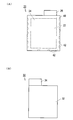
- FIG. 1 is a perspective view showing the appearance of a lithium ion secondary battery.
- FIG. 2 is an exploded perspective view of the lithium ion secondary battery.
- FIG. 3A is a plan view of the packaged positive electrode
- FIG. 3B is a plan view of the negative electrode.
- FIG. 4 is a plan view showing a state in which the negative electrode is stacked on the packaged positive electrode.
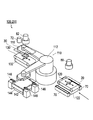
- FIG. 5 is a schematic plan view showing the sheet laminating apparatus.
- FIG. 6 is a perspective view showing the sheet laminating apparatus.
- FIG. 7 is a front view of the positive electrode supply table viewed in the direction of the arrow in FIG.
- FIG. 8 is a plan view of the positive electrode supply table.
- FIG. 1 is a perspective view showing the appearance of a lithium ion secondary battery.
- FIG. 2 is an exploded perspective view of the lithium ion secondary battery.
- FIG. 3A is a plan view of the packaged positive electrode
- FIG. 3B is a plan view of
- FIG. 9A is a perspective view showing a state in which the suction hand is positioned above the stacking stage and above the negative electrode supply table in the stacking operation of the negative electrode and the packaged positive electrode by the stacking robot, and FIG. It is a perspective view which shows a mode that the adsorption
- FIG. 10C is a perspective view showing a state in which the L-shaped arm is raised by a predetermined amount in the laminating operation of the negative electrode and the packaged positive electrode by the laminating robot, and FIG. 10D is the predetermined amount of the L-shaped arm. It is a perspective view which shows a mode that it rotated.
- FIG. 11E is a perspective view showing a state in which the L-shaped arm is lowered by a predetermined amount in the stacking operation of the negative electrode and the packaged positive electrode by the stacking robot.
- FIG. It is a perspective view which shows a mode that the L-shaped arm raised only the predetermined amount in lamination
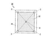
- FIG. 12 is a conceptual diagram showing how the position of the positive electrode in the packed positive electrode is confirmed.
- FIG. 13 is a conceptual diagram showing the position of the detected positive electrode.
- FIG. 14 is a conceptual diagram showing a state in which the position of the positive electrode in the packaged positive electrode is confirmed.
- FIG. 14 (A) is a front view of the laminate when the position of the positive electrode of the packaged electrode is confirmed.
- FIG. 14B is a conceptual diagram of the stacked body as viewed from above.
- FIG. 15 is a conceptual diagram showing the state of the positive electrode whose side position is specified.
- FIG. 16 is a concept showing how to confirm the position of the negative electrode
- FIG. 16 (A) is a conceptual view of the laminate when confirming the position of the negative electrode as viewed from the front, and FIG. It is the conceptual diagram which looked at the laminated body from the plane.
- FIG. 17 is a conceptual diagram showing the state of the negative electrode whose side position is specified.
- FIG. 18 is a conceptual diagram showing the relative positions of the positive electrode 24 and the negative electrode.
- FIG. 19 is a conceptual diagram showing how the position of the negative electrode is determined.
- FIG. 20 is a schematic diagram showing the transmission characteristics of the separator.
- FIG. 20 is a schematic diagram showing the transmission characteristics of the separator.
- FIG. 21 is a perspective view showing another sheet laminating apparatus.
- FIG. 22 is a front view of the positive electrode supply table viewed in the direction of the arrow in FIG.
- FIG. 23A is a conceptual diagram showing a state of confirming the position of the positive electrode in the packaged positive electrode
- FIG. 23B is a conceptual diagram showing a state of confirming the position of the separator.
- FIG. 24 is a conceptual diagram showing how the position of the positive electrode is determined.
- FIG. 25 is a schematic view showing an example of a state where the separator is turned up.
- the present invention relates to an electrode position detection device applied to a part of a manufacturing process of a secondary battery.
- a sheet stacking apparatus that is a structure for assembling a battery structure and a power generation element of the battery will be described.
- FIG. 1 is a perspective view showing the appearance of a lithium ion secondary battery
- FIG. 2 is an exploded perspective view of the lithium ion secondary battery
- FIG. 3 is a plan view of a negative electrode and a packaged positive electrode
- FIG. It is a top view which shows a mode that it piled up.
- the lithium ion secondary battery 10 has a flat rectangular shape, and the positive electrode lead 11 and the negative electrode lead 12 are led out from the same end portion of the exterior material 13.
- a power generation element (battery element) 15 in which a charge / discharge reaction proceeds is accommodated in the exterior material.
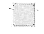
- the power generation element 15 is formed by alternately stacking the packaged positive electrode 20 and the negative electrode 30.
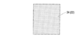
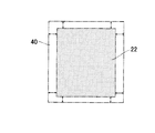
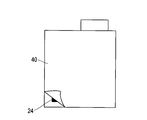
- the packaged positive electrode 20 is formed by sandwiching a positive electrode 24 in which a positive electrode active material layer 22 is formed on both surfaces of a sheet-like positive electrode current collector between separators 40.
- the two separators 40 are joined to each other by a joining portion 42 at an end portion, and are formed in a bag shape.
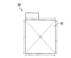
- the tab portion 26 is pulled out from the bag of the separator 40.
- the positive electrode active material layer 22 is formed in a portion other than the tab portion 26.
- the negative electrode 30 has a negative electrode active material layer 32 formed on both surfaces of a very thin sheet-like negative electrode current collector.
- a negative electrode active material layer 32 is formed in a portion other than the tab portion 34.
- the negative electrode active material layer 32 is formed to be slightly larger than the positive electrode active material layer 22 of the positive electrode 24 in plan view.
- FIG. 5 is a schematic plan view showing the sheet laminating apparatus
- FIG. 6 is a perspective view showing the sheet laminating apparatus
- FIG. 7 is a front view of the positive electrode supply table viewed in the direction of the arrow in FIG. 6, and FIG. It is.
- the sheet stacking apparatus 100 includes a stacking robot 110, a positive electrode supply table 120, a negative electrode supply table 130, a stacking stage 140, a storage unit 150, and a control unit 160.
- the stacking robot 110, the positive electrode supply table 120, the negative electrode supply table 130, and the stacking stage 140 are controlled by the control unit 160.
- the control program and various data of the control unit 160 are stored in the storage unit 150.
- the stacking robot 110 alternately stacks the packed positive electrodes 20 and the negative electrodes 30 to form a power generation element (laminated body) 15.
- the stacking robot 110 includes an L-shaped arm 112 and first and second suction hands 114 and 116 provided at end portions of the L-shaped arm 112.
- the L-shaped arm 112 rotates a predetermined angle in the horizontal direction, for example, 90 degrees in this embodiment. Further, the L-shaped arm 112 can move a predetermined amount in the vertical direction.
- the first suction hand 114 is provided at one end of the L-shaped arm 112 and holds or releases the packaged positive electrode 20 by suction.
- the second suction hand 116 is provided at the other end of the L-shaped arm 112 and holds or releases the negative electrode 30 by suction.
- the positive electrode supply table 120 is a table for delivering the packaged positive electrode 20 to the L-shaped arm 112.
- the positive electrode supply table 120 receives and places the packed positive electrodes 20 created in the previous process and transported by the suction conveyor 60 one by one.
- the positive electrode supply table 120 is also an adsorption conveyor, and adsorbs the packed positive electrode 20 from which the negative pressure from the adsorption conveyor 60 is released, carries it to the approximate center, and fixes it by the negative pressure. Further, the positive electrode supply table 120 can be moved and rotated in the planar direction so that the planar position of the packaged positive electrode 20 can be adjusted.
- the positive electrode supply table 120 is provided on, for example, an XY stage 122, and the planar position is adjusted by the XY stage 122 moving in the X and Y directions or rotating in the planar direction.
- the XY stage 122 is moved and rotated in the plane direction by three motors.
- the positive electrode supply table 120 is narrower than the suction conveyor 60 and is configured so that the side of the packaged positive electrode 20 protrudes.
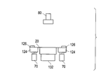
- transparent support bases 124 are provided on both sides of the positive electrode supply table 120 as shown in FIGS. 7 and 8.
- the support table 124 supports the end of the packaged positive electrode 20 protruding from the positive electrode supply table 120.
- a clamper 126 is provided at a position corresponding to the support base 124. The clamper 126 is fixed by sandwiching the end portion of the packed positive electrode 20 together with the support base 124.
- Both the support base 124 and the clamper 126 are movable, and when the packaged positive electrode 20 is placed on the positive electrode supply table 120, the packaged positive electrode 20 is attached to the packaged positive electrode 20 so as to support and fix the end of the packaged positive electrode 20. approach.
- a light source 70 is disposed below the positive electrode supply table 120, and a camera 80 is disposed above.
- the light source 70 is installed below the transparent support base 124 and irradiates light to the end of the packaged positive electrode 20.
- the irradiated light is light having a wavelength that passes through the separator 40 at a predetermined transmittance or more and does not pass through the positive electrode 24.
- the camera 80 receives light transmitted from the light source 70 and blocked by the positive electrode 24 while passing through the separator 40, and images the position of the positive electrode 24. That is, the position of the positive electrode 24 is imaged based on the shadow of the positive electrode 24.
- the horizontal position of the positive electrode 24 (packed positive electrode 20) is adjusted. By this adjustment, the suction hand 114 can pick up the packaged positive electrode 20 in which the position of the positive electrode 24 is accurately positioned every time.
- the negative electrode supply table 130 is a table for delivering the negative electrode 30 to the L-shaped arm 112.
- the negative electrode supply table 130 receives and places the negative electrodes 30 created in the previous process and transported by the suction conveyor 62 one by one.
- the negative electrode supply table 130 is also an adsorption conveyer, and adsorbs the negative electrode 30 from which the negative pressure from the adsorption conveyer 62 is released, carries it to approximately the center, and fixes it by the negative pressure.
- the negative electrode supply table 130 releases the suction. Further, the negative electrode supply table 130 can be moved and rotated in the planar direction so that the planar position of the negative electrode 30 can be adjusted.
- the negative electrode supply table 130 is provided on, for example, an XY stage 132, and the plane position is adjusted by the XY stage 132 moving in the X and Y directions or rotating in the plane direction.
- the XY stage 132 is moved and rotated in the plane direction by three motors.
- a light source 72 and a camera 82 are arranged above the negative electrode supply table 130.
- the light source 72 irradiates the negative electrode 30 with light having a wavelength reflected or absorbed by the negative electrode 30.
- the camera 82 receives the light projected from the light source 72 and reflected by the negative electrode 30, or the light reflected around without being absorbed by the negative electrode 30, and images the position of the negative electrode 30.
- the horizontal position of the negative electrode 30 is adjusted based on the position of the negative electrode 30 captured by the camera 82. By this adjustment, the suction hand 116 can pick up the accurately positioned negative electrode every time.
- the stacking stage 140 is disposed on the mounting portion 142 for mounting the pallet on which the packaged positive electrode 20 and the negative electrode 30 are alternately stacked, the driving portion 144 for moving the mounting portion 142 up and down, and the peripheral portion of the mounting portion 142. And four clampers 146.
- the mounting unit 142 holds the stacked body 15 until a predetermined number of the packed positive electrodes 20 and the negative electrodes 30 are stacked and the power generation element 15 is completed.
- the mounting section 142 delivers the power generation element 15 to the conveyor 64.
- the drive unit 144 adjusts the height of the placement unit 142. Specifically, the packaged positive electrode 20 and the negative electrode 30 are alternately stacked, and placed according to the progress of the stacking so that the height of the top surface of the stacked body 15 does not change even if the height of the stacked body 15 varies. The position of the part 142 is lowered. Thereby, the stacking robot 110 can stack the power generating elements 15 only by repeating the same operation regardless of the progress of the stacking.
- the clamper 146 fixes the four corners of the laminated body 15 every time the negative electrode 30 or the packaged positive electrode 20 is laminated so that the laminated body 15 is not displaced. Since the height of the mounting portion 142 is adjusted to be lower as the stacking progresses, the clamper 146 can repeat clamping with the same stroke every time.
- the packed positive electrode 20 and the negative electrode 30 placed on the positive electrode supply table 120 and the negative electrode supply table 130 after being adjusted in position are picked up by the laminating robot 110 and laminated. Alternately provided to the stage 140.
- the stacking operation of the sheet stacking apparatus 100 will be described with reference to FIGS.
- 9 to 11 are diagrams for explaining the stacking operation of the negative electrode and the packed positive electrode by the stacking robot. In the following, the operation when the packaged positive electrode 20 is stacked on the stacking stage 140 by the stacking robot 110 will be described.
- the packaged positive electrode 20 and the negative electrode 30 are placed on the stacking stage 140, and the suction hand 114 is positioned above the stacking stage 140.
- the negative electrode 30 is disposed in the uppermost layer of the stacked positive electrode 20 and negative electrode 30, and the suction hand 114 holds the packed positive electrode 20 by suction.
- the suction hand 116 is located above the negative electrode supply table 130.
- the negative electrode 30 is placed on the negative electrode supply table 130.
- the L-shaped arm 112 of the stacking robot 110 is lowered by a predetermined amount (see FIG. 9B).
- the suction hand 116 and the suction hand 114 are lowered onto the negative electrode supply table 130 and the stacking stage 140, respectively.
- negative pressure acts on the bottom surface of the suction hand 116, and the suction hand 116 sucks and holds the negative electrode 30.
- the negative pressure is released from the suction hand 114 and the packaged positive electrode 20 is released.
- the L-shaped arm 112 of the stacking robot 110 is raised by a predetermined amount (see FIG. 10C).
- the suction hand 116 picks up the negative electrode 30 from the negative electrode supply table 130.
- the suction hand 116 and the suction hand 114 move on the negative electrode supply table 130 and above the stacking stage 140.
- the L-shaped arm 112 of the stacking robot 110 rotates by a predetermined amount (see FIG. 10D).
- the suction hand 116 is positioned above the stacking stage 140 and the suction hand 114 is positioned above the positive electrode supply table 120.
- the L-shaped arm 112 of the stacking robot 110 is lowered by a predetermined amount (see FIG. 11E).
- the suction hand 116 and the suction hand 114 reach the stacking stage 140 and the positive electrode supply table 120, respectively.
- the negative pressure of the suction hand 116 is released, and the suction hand 116 releases the negative electrode 30 on the uppermost surface of the stacked body on the stacking stage 140.
- a negative pressure is generated on the bottom surface of the suction hand 114, and the suction hand 114 sucks and holds the packaged positive electrode 20 on the positive electrode supply table 120.
- the L-shaped arm 112 of the stacking robot 110 is raised by a predetermined amount (see FIG. 11F).
- the suction hand 116 moves above the stacking stage 140.
- the suction hand 114 picks up the packed positive electrode 20 from the positive electrode supply table 120.
- the L-shaped arm 112 of the stacking robot 110 rotates by a predetermined amount.
- the suction hand 116 is positioned above the negative electrode supply table 130 and the suction hand 114 is positioned above the stacking stage 140 (FIG. 9 (A)).
- the packed positive electrode 20 and the negative electrode 30 are alternately stacked on the stacking stage 140.
- a laminate as the power generation element 15 is formed.
- Electrode position detection apparatus 200 Next, the electrode position detection apparatus 200 applied to the sheet laminating apparatus 100 will be described.
- the electrode position detection apparatus 200 includes a light source 70, a camera 80, an XY stage 122, and a control unit 160.
- the light source 70 and the camera 80 are each connected to the control unit 160, and the operation is controlled by the control unit 160.
- the electrode position detection device 200 includes a configuration common to the above-described sheet stacking device 100.
- the light source 70 is installed below the positive electrode supply table 120 as the first light projecting means.
- the camera 80 is installed on the side opposite to the light source 70 with respect to the packaged positive electrode 20 as a light receiving means.
- the camera 80 images the positive electrode 24 in the packaged positive electrode 20.
- the light source 70 projects light having a wavelength that passes through the separator 40 and does not pass through the positive electrode 24 (reflected or absorbed), for example, red light, toward the packaged positive electrode 20.
- the light from the light source 70 passes through the transparent support 124 and is projected onto the end of the packaged positive electrode 20. Since the central portion of the packaged positive electrode 20 is hidden by the positive electrode supply table 120, the light from the light source 70 is not irradiated.
- the longer the wavelength of light the higher the transmittance, but the transmittance varies depending on the material.
- the wavelength of the light to be projected needs to be set as appropriate. Details on how to set the wavelength of the light to be projected will be described later.
- the control part 160 detects the position of the positive electrode 24 based on the imaging by the camera 80 as a detection means.
- an operation (electrode position detection method) of the electrode position detection device 200 when detecting the position of the positive electrode 24 will be described.
- FIG. 12 is a conceptual diagram showing how to check the position of the positive electrode in the packaged positive electrode
- FIG. 13 is a conceptual diagram showing the position of the detected positive electrode
- FIG. 14 is a conceptual diagram showing how the position of the negative electrode is determined. .
- the packed positive electrode 20 is placed on the positive electrode supply table 120, the end of the packed positive electrode 20 is supported by the transparent support base 124, and fixed by the clamper 126. After fixing, the electrode position detection device 200 projects light by the light source 70 before the packed positive electrode 20 is sucked by the suction hand 114.
- the projected light passes through the end of the separator 40 and does not pass through the positive electrode 24.
- the camera 80 receives light that has passed through the separator 40. That is, the camera 80 receives light in which the portion of the positive electrode 24 is shaded via the positive electrode 24.
- the position of the positive electrode 24 can be detected by detecting the shadow outline. However, since the light is not originally transmitted through the portion where the positive electrode 24 is hidden by the positive electrode supply table 120, the position of the positive electrode 24 cannot be detected. For example, as shown in a colored manner in FIG. 12, the shape and position of the end of the positive electrode 24 are confirmed.
- the control unit 160 analyzes the image and specifies the side of the positive electrode 24 in the range indicated by the double arrow in the figure.
- the specified side is extended to specify the position of the entire side of the positive electrode 24.
- the positive electrode 24 has the tab part 26, as shown in FIG. 12, the edge of the coating part in which the positive electrode active material layer 22 was formed is specified. Therefore, the positive electrode 24 in which the position of the entire side is specified is specified as a rectangle as shown in FIG.
- a rectangular square C is calculated from the intersection of the sides as shown by the dotted line in FIG. Furthermore, the center point of the positive electrode 24 is calculated by averaging the calculated positions of the square C. In addition, the inclination of the positive electrode 24 in the planar direction is also calculated based on the specified side posture. The calculated position information and inclination of the center point O of the positive electrode 24 are stored in the storage unit 150.
- the control unit 160 reads the position information and inclination of the center point O of the positive electrode 24 from the storage unit 150, and controls the XY stage 122 so that the center point O is a predetermined position and the positive electrode 24 is in a constant posture.
- the XY stage 122 adjusts the position of the positive electrode 24 by moving / rotating the packaged positive electrode 20 in the plane direction. That is, the XY stage 122 functions as a position adjusting unit.
- the position of the positive electrode 24 is adjusted so that the suction hand 114 becomes a reference position for picking up the packaged positive electrode 20 in order to accurately stack the positive electrode 24 and the negative electrode 30 in the stacking stage 140.
- the position of the positive electrode 24 itself arranged in the separator 40 formed in a bag shape is detected. Therefore, not the separator 40 but the position of the packed positive electrode 20 can be adjusted based on the detected position of the positive electrode 24.
- the positive electrode 24 is always delivered to the suction hand 114 at a predetermined position.
- the stacking robot 110 can accurately stack the positive electrode 24 without shifting from the stacked body 15. That is, it can be accurately positioned indirectly with the negative electrode 30.
- the suction hand 114 and the XY stage 122 can cooperate to appropriately stack the packaged positive electrode 20 on the negative electrode 30 based on the detected position of the positive electrode 24 as a stacking unit.
- the electrode position detection device 200 detects not only the position of the positive electrode 24 but also the position of the negative electrode 30.
- the electrode position detection apparatus 200 further includes a light source 72, a camera 82, and an XY stage 132.
- the electrode position detection device 200 projects light from the light source 72 to the negative electrode 30 placed on the negative electrode supply table 130.
- the light to be projected may be any light as long as it has a wavelength that does not pass through the negative electrode 30 (is reflected or absorbed). For example, white light is projected.
- the projected light is reflected by the negative electrode 30.
- the camera 82 receives the reflected light through the negative electrode 30 and images the negative electrode 30.
- the captured negative electrode 30 is as shown in FIG.
- the control unit 160 analyzes the imaging result and detects each side of the negative electrode 30. Further, the control unit 160 calculates the position of the square c of the negative electrode 30 as the detected intersection of each side.
- the control unit 160 calculates the average of the calculated positions of the square c and calculates the center point o of the negative electrode 30. In addition, the inclination of the positive electrode 24 in the planar direction is also calculated based on the specified side posture. The calculated position information and inclination of the center point o of the negative electrode 30 are stored in the storage unit 150.
- the control unit 160 reads the center point o and the inclination of the negative electrode 30 from the storage unit 150, and controls the XY stage 132 so that the center point o is located at a predetermined position and the negative electrode 30 is in a constant posture.
- the XY stage 132 adjusts the position of the negative electrode 30 by moving / rotating the negative electrode 30 in the planar direction.
- the XY stage 132 functions as a position adjusting unit. Thereby, not only the positive electrode 24 but also the negative electrode 30 is delivered to the suction hand 116 at the same position every time.
- the position of the negative electrode 30 is adjusted so that the suction hand 116 becomes a reference position for picking up the negative electrode 30 in order to accurately stack the positive electrode 24 and the negative electrode 30 in the stacking stage 140.
- the accurate stacking of the positive electrode 24 and the negative electrode 30 is a stack determined to have no stacking deviation, and the determination is performed as follows.
- FIG. 14 is a conceptual diagram showing a state of confirming the position of the positive electrode 24 in the packaged positive electrode
- FIG. 15 is a conceptual diagram showing a state of the positive electrode 24 in which the position of the side is specified
- FIG. 17 is a conceptual diagram showing a state of the negative electrode 30 in which the position of the side is specified
- FIG. 18 is a conceptual diagram showing a relative position between the positive electrode 24 and the negative electrode 30.
- 14A is a conceptual diagram of the laminated body when confirming the position of the positive electrode 24 of the packaged electrode as seen from the front
- FIG. 14B is a conceptual diagram of the laminated body as seen from the plane. is there.
- FIG. 16A is a conceptual diagram of the laminate when the position of the negative electrode 30 is confirmed as seen from the front
- FIG. 16B is a conceptual diagram of the laminate as seen from the plane.
- the packaged positive electrode 20 and the negative electrode 30 are alternately laminated by the sheet laminating apparatus 100.
- the electrode position detection device 200 projects light from the light source 70 onto the packaged positive electrode 20 in the uppermost layer of the laminate 15.
- the electrode position detecting device 200 projects light onto the packaged positive electrode 20 by the light source 70.
- the projected light passes through the separator 40 of the packaged positive electrode 20 and is reflected by the positive electrode 24.
- a camera (not shown) receives the reflected light via the positive electrode 24.
- the camera images a region indicated by a dotted line in FIG.
- One camera is installed.
- the camera is preferably a camera with a wide field of view.
- four cameras that capture each of the regions indicated by dotted lines in FIG. 14B may be used.
- the control unit 160 analyzes the image and specifies a part of the side of the positive electrode 24 in the range indicated by the double arrow in the drawing.
- the control unit 160 extends a part of the specified side of the positive electrode 24 and specifies the position of the side of the positive electrode active material layer 22 that is a coating portion of the positive electrode 24. Thereby, the position of the specified side is expressed in a rectangle as shown in FIG.
- the specified position information of the side of the positive electrode active material layer 22 is stored in the storage unit 150 as information indicating the position of the positive electrode 24.
- the camera can also identify the position of the separator 40 by photographing the packaged positive electrode 20 in the absence of light from the light source.
- the position information of the specified side of the separator 40 may also be stored in the storage unit 150. Thereby, the relative position of the positive electrode 24 with respect to the separator 40 can also be specified.
- Part of the transmitted light is transmitted through the separator 40 at the outer peripheral portion of the positive electrode 24, further transmitted through the separator 40, and reflected by the negative electrode 30.
- the camera receives the reflected light, but receives light that is weaker than the reflected light reflected from the positive electrode 24. Therefore, the image that has been imaged is thinner than in the case of the positive electrode 24. Therefore, the negative electrode 30 can be reliably compared with the positive electrode 24 in an image state.
- the electrode position detection device 200 projects light onto the negative electrode 30 by the light source 72.
- the projected light is reflected by the negative electrode 30.
- the camera receives reflected light via the negative electrode 32.
- the camera images a region indicated by a dotted line in FIG.
- the control unit 160 analyzes the image and specifies a part of the side of the negative electrode 30 in the range indicated by the double arrow in the drawing.
- the control unit 160 extends a part of the specified side of the negative electrode 30 and specifies the position of the side of the negative electrode active material layer 32 that is a coating portion of the negative electrode 30.
- the specified position information of the side of the negative electrode active material layer 32 is stored in the storage unit 150 as information indicating the position of the negative electrode 30.
- the camera can also identify the position of the separator 40 by photographing the end of the packaged positive electrode 20 laminated under the negative electrode 30 in the absence of light from the light source. Since the separator 40 is larger than the negative electrode 30, even if the negative electrode 30 is laminated on the separator 40, it can be photographed with a camera if it is only at the end.
- the position information of the sides of the separator 40 specified by photographing may also be stored in the storage unit 150. Thereby, the relative position of the negative electrode 30 with respect to the separator 40 can also be specified.
- control unit 160 sequentially detects the positions of the positive electrode 24 and the negative electrode 30 (the relative position of the positive electrode 24 with respect to the separator 40 and the relative position of the negative electrode 30 with respect to the separator 40) and stores them in the storage unit 150.
- the controller 160 determines whether the negative electrode 30 and the positive electrode 24 have a stacking deviation after the stacked body 15 is completed as a battery element or during the stacking of the stacked body 15.
- the control unit 160 When determining the stacking deviation, the control unit 160 reads the positional information of the sides of the positive electrode 24 and the negative electrode 30 from the storage unit 150 and detects the relative positional relationship between the two. At the time of detection, the positions of the positive electrode 24 and the negative electrode 30 specified in FIGS. 15 and 17 are overlapped. The superposed conceptual diagram is as shown in FIG. The control unit 160 analyzes the superimposed result and determines the relative positional relationship between the positive electrode 24 and the negative electrode 30. Specifically, the positions of the sides of the positive electrode 24 and the negative electrode 30 are confirmed, and it is confirmed whether the corresponding sides are within a predetermined range.
- the control unit 160 determines that there is no stacking deviation when all sides of the positive electrode 24 are inside the negative electrode 30. Not only whether the side is the inner side or the outer side, but the distance between the sides may be calculated to determine the stacking deviation within the range of the distance.
- both the positive electrode 24 and the negative electrode 30 are taken from the suction hands 114 and 116 at the same position each time. Therefore, also in the lamination stage 140, the negative electrode 30 and the positive electrode 24 are laminated at the same position every time, and the accurate lamination of the power generating elements 15 can be achieved.
- the contour of the positive electrode 24 can be specified.
- FIG. 20 is a schematic diagram showing the transmission characteristics of the separator.
- the horizontal axis indicates the wavelength of light (nm), and the vertical axis indicates the light transmittance (%).
- FIG. 20 shows the transmission characteristics of three types of separators, that is, a polypropylene separator, a polyethylene separator, and a ceramic separator.
- the polypropylene separator and the polyethylene separator are polymer skeletons formed of polypropylene and polyethylene, respectively.
- the ceramic separator is a polypropylene base material coated with a porous film formed by bonding ceramic particles such as silica, alumina, zirconium oxide, titanium oxide and a binder.
- the separator 40 has a different transmission tendency depending on the material. However, for any material, it can be seen that the longer the wavelength, the higher the transmittance.
- the positive electrode 24 when the positive electrode 24 is detected, it is necessary to project light having a wavelength that passes through the separator 40 from the light source 70.
- light having a wavelength such that at least the transmittance of the separator is 50% or more is projected from the light source 70.
- the transmittance is 50% or more, the positive electrode 24 can be detected by reliably transmitting the separator 40.
- the positive electrode 24 is made of a metal such as aluminum or copper, light hardly transmits. Accordingly, there is no particular upper limit as long as even the separator 40 has a wavelength that allows transmission.
- the wavelength of light to be projected can be set based on the transmittance with respect to the separator 40 regardless of the material of the separator 40. That is, the lower limit of the wavelength can be set by the transmittance (50% or more) with respect to the separator 40.
- ceramic separator having the transmission characteristics shown in FIG. 20 when the ceramic separator having the transmission characteristics shown in FIG. 20 is employed, light having a wavelength of about 1300 nm or more, for example, near infrared light can be used. Ceramic separators are less permeable to light than polypropylene separators and polyethylene separators, but can be transmitted by using near infrared light.
- the light source 70 is provided at a position facing the camera 80.
- the positional relationship between the light source 70 and the camera 80 is not limited to this.
- the light source 70 and the camera 80 may be provided on the same side with respect to the packaged positive electrode 20.
- the light emitted from the light source 70 passes through the separator 40, is reflected by the positive electrode 24, and is imaged by the camera 80. That is, the camera 80 images the reflected light of the positive electrode 24 instead of the shadow of the positive electrode 24.
- the positive electrode lead 11 and the negative electrode lead 12 are led out from the same end portion of the exterior member 13 as shown in FIG. 1 .
- the positive electrode lead 11 and the negative electrode lead 12 may be led out from opposite ends, for example.
- the packaged positive electrode 20 and the negative electrode 30 are laminated so that the tab portions 26 and 34 are opposite to each other.
- the reference position of the positive electrode 24 for the suction hand 114 to pick up the packed positive electrode 20 is set in advance, and the position of the packed positive electrode 20 is set so that the positive electrode 24 is positioned at the reference position. Is corrected.
- the position of the negative electrode 30 is detected by the electrode position detection device 200 and the position is adjusted.
- the position of the negative electrode 30 can be stored in the storage unit 150.
- a reference position for picking up the positive electrode 24 may be calculated based on the stored position of the negative electrode 30, and the position of the packaged positive electrode 20 may be adjusted so that the positive electrode 24 is positioned at the calculated reference position.
- the reference position matches the position of the positive electrode 24 the position of the positive electrode 24 need not be adjusted.
- the deviation between the reference position and the position of the positive electrode 24 is within a predetermined error range, the position of the positive electrode 24 may not be adjusted.
- FIG. 22 is a front view of the positive electrode supply table viewed in the direction of the arrow in FIG.
- the electrode position detection apparatus 200 includes light sources 70 and 74, a camera 80, and a control unit 160.
- the light sources 70 and 74 and the camera 80 are each connected to the control unit 160, and the operation is controlled by the control unit 160.
- the electrode position detection device 200 includes a configuration common to the above-described sheet stacking device 100.
- the light source 70 is installed below the positive electrode supply table 120 as the first light projecting means.
- the camera 80 is installed as the first and second light receiving means on the side opposite to the light source 70 with respect to the packaged positive electrode 20.
- the camera 80 images the positive electrode 24 in the packaged positive electrode 20.
- the light source 70 projects light (first light) having a wavelength that passes through the separator 40 and does not pass through the positive electrode 24 (reflected or absorbed), for example, red light, toward the packaged positive electrode 20.
- the light from the light source 70 passes through the transparent support 124 and is projected onto the end of the packaged positive electrode 20. Since the central portion of the packaged positive electrode 20 is hidden by the positive electrode supply table 120, the light from the light source 70 is not irradiated.
- the light source 74 is disposed on the same side as the camera 80 with respect to the packaged positive electrode 20 as the second light projecting means.
- the light source 74 projects light having a wavelength (second light) reflected by the separator 40 toward the packaged positive electrode 20, for example, white light. It is known that the longer the wavelength of light, the higher the transmittance, but the transmittance varies depending on the material. Based on the material of the separator 40, the wavelength of the light to be projected needs to be set as appropriate. Details on how to set the wavelength of the light to be projected will be described later.
- the control part 160 detects the position of the positive electrode 24 and the separator 40 based on the imaging by the camera 80 as a detection means.
- an operation (electrode position detection method) of the electrode position detection device 200 when detecting the position of the positive electrode 24 will be described.
- FIG. 23A is a conceptual diagram showing how to check the position of the positive electrode in the packaged positive electrode
- FIG. 23B is a conceptual diagram showing how to check the position of the separator
- FIG. 24 determines the position of the positive electrode. It is a conceptual diagram which shows a mode.
- the packed positive electrode 20 is placed on the positive electrode supply table 120, the end of the packed positive electrode 20 is supported by the transparent support base 124, and fixed by the clamper 126.
- the electrode position detection device 200 projects light by the light sources 70 and 74 before the packed positive electrode 20 is sucked by the suction hand 114.
- the light projection is performed sequentially rather than simultaneously. For example, light projection by the light source 70 is performed first.
- the projected light passes through the end of the separator 40 and does not pass through the positive electrode 24.
- the camera 80 receives light that has passed through the separator 40. That is, the camera 80 receives light in which the portion of the positive electrode 24 is shaded through the positive electrode 24.
- the position of the positive electrode 24 can be detected by detecting the shadow outline. However, since the light is not originally transmitted through the portion where the positive electrode 24 is hidden by the positive electrode supply table 120, the position of the positive electrode 24 cannot be detected. For example, as shown in a colored manner in FIG. 23A, the shape and position of the end portion of the positive electrode 24 are confirmed.
- the control unit 160 analyzes the image and specifies the side of the positive electrode 24 in the range indicated by the double arrow in the figure.
- the specified side is extended to specify the position of the entire side of the positive electrode 24.
- the positive electrode 24 has the tab part 26, as shown to FIG. 23 (A), the edge
- the position information of the specified side of the positive electrode 24 is stored in the storage unit 150.
- the light source 74 projects light onto the packaged positive electrode 20.
- the projected light is reflected by the separator 40 and received by the camera 80.
- the camera 80 receives the entire image of the separator 40.
- the position of the separator 40 is confirmed.
- the control unit 160 analyzes the image and specifies the side of the separator 40 in the range indicated by the double-headed arrow in the figure.
- the position information of the specified side of the separator 40 is stored in the storage unit 150.
- the control unit 160 reads the position information of the sides of the separator 40 and the positive electrode 24 from the storage unit 150, and confirms the position of the positive electrode 24 with respect to the position of the separator 40. For example, as shown in FIG. 24, the control unit 160 superimposes the positions of the sides of the separator 40 and the positive electrode 24 and measures the distance between the positions indicated by the double arrows. Here, the superposed positive electrode 24 is only a portion included in the separator 40 without the tab portion 26. And it is determined whether the position of the positive electrode 24 is normal or abnormal by determining whether or not the measured distance is within a predetermined range.
- the predetermined range is set in advance as a range of distances from each side of the separator 40 and is appropriately determined according to the standard of the packaged positive electrode 20 or the like.
- the control unit 160 finds that the position of at least one side of the positive electrode 24 is not within a predetermined range with respect to the position of the side of the separator 40, the control unit 160 discharges the found packaged positive electrode 20 by the stacking robot 110, It can be incorporated into the power generation element 15 or stored in the storage unit 150 and discharged as a defective product in a later process.
- the position of the positive electrode 24 itself arranged in the bag-shaped separator 40 can be detected, and the relative position with respect to the separator 40 can be detected. Therefore, it can be reliably inspected whether the relative position is within the allowable range, that is, whether or not the positive electrode 24 is accurately positioned in the separator 40. As a result, it is possible to prevent the power generation element 15 from being formed and shipped while the positive electrode 24 that has been misaligned is packed in the separator 40. Since the position of the separator 40 is also detected, the quality of the position of the positive electrode 24 can be determined based on the relative positional relationship with the separator 40.
- the camera 80 can receive light from both the light source 70 and the light source 74 in common. Therefore, it is not necessary to prepare a camera for each of the light sources 70 and 74, and equipment costs can be reduced.
- the contour of the positive electrode 24 can be specified.
- the light source 74 irradiates light that does not pass through the separator 40 so much, for example, light having a wavelength with a transmittance of 50% or less.
- the electrode position detection device 200 detects the position of the positive electrode 24 for the packaged positive electrode 20 placed on the positive electrode supply table 120.
- the present invention is not limited to this.
- the electrode detection by the electrode position detection device 200 can be applied to any process as long as the packaged positive electrode 20 is formed.
- the position of the positive electrode 24 relative to the separator 40 may be detected immediately after the positive electrode 24 is sandwiched between two separators 40 and packed in a bag.
- whether the relative position of the positive electrode 24 is good or bad is determined based on whether or not the position of the side of the positive electrode 24 is within a predetermined range with reference to the position of the side of the separator 40.
- the reference for evaluating the relative position of the positive electrode 24 is not limited to this.
- the respective corners are calculated from the positions of the sides of the separator 40 and the positive electrode 24, the respective central positions are calculated from the average positions of the corners, and the positions of the positive electrodes 24 are determined based on the deviation between the central positions. May be evaluated.
- each of the light sources 70 and 74 may be provided with a light receiving camera.
- the light sources 70 and 74 can be arranged on the same side or the design can be changed.
- the positive electrode lead 11 and the negative electrode lead 12 are led out from the same end portion of the exterior member 13 as shown in FIG. 1 .
- the positive electrode lead 11 and the negative electrode lead 12 may be led out from opposite ends, for example.
- the negative electrode 30 and the packaged positive electrode 20 are laminated so that the tab portions 26 and 34 are opposite to each other.
- the relative position of the positive electrode 24 with respect to the separator 40 is detected.
- the camera 80 also images the separator 40 itself. Accordingly, whether or not the separator 40 is normal may be determined based on the imaging result of the separator 40 itself.
- FIG. 25 is a schematic diagram showing an example of a state in which turning is generated in the separator. As shown in FIG. 25, the control unit 160 can detect that the separator 40 is abnormal when the lower left corner of the separator 40 is turned over.
- the occurrence of turning can be detected as follows.
- the controller 160 irradiates light from the light source 74 and receives light reflected by the separator 40 by the camera 80.
- the control unit 160 analyzes the image picked up by the camera 80 and distinguishes the separator 40 that looks white and the positive electrode 24 that looks black. For example, the positive electrode 24 is detected based on a difference in image brightness. When the black positive electrode 24 is detected in a range where the separator 40 should be, it can be detected that the separator 40 is turned over and the positive electrode 24 is exposed.
- the detection of turning over of the separator 40 can be performed simultaneously with the determination of the relative position of the positive electrode 24 with respect to the separator 40.
- the turning of the separator 40 can be detected, and the defect of the packaged positive electrode 20 can be detected with higher accuracy.
- the joining portion 42 is formed.
- the joining portion 42 that joins the separators 40 has different physical properties from the original separator 40, and the light transmittance is also different from the portions other than the joining portions 42.
- the transmittance of the joint portion 42 is lower than that of the other separators 40. Therefore, by adjusting the wavelength of light projected from the light source 70, the position of the joint portion 42 can also be detected when the position of the positive electrode 24 is detected.
- the position of the detected joint 42 can be evaluated by comparing with the position of the separator 40 detected in the above embodiment. That is, as in the case of the positive electrode 24, the distance of the corresponding joint portion 42 is calculated based on the position of each side of the separator 40. If the calculated distance is within a predetermined range, the position of the joint portion 42 is normal. If it is out of range, it is determined to be abnormal.
- Positive electrode 4 Separator 10 Lithium ion secondary battery 11 Positive electrode lead 12 Negative electrode lead 15 Power generation element, laminated body 20 Packed positive electrode 24 Positive electrode 30 Negative electrode 32 Negative electrode active material layer 34 Tab portion 40 Separator 60, 62 Adsorption conveyor 70, 72, 74 Light source 80, 82 Camera 100 Sheet laminating device 110 Laminating robot 112 L-shaped arm 114, 116 Suction hand 120 Positive electrode supply table 122 XY stage 124 Support base 126 Clamper 130 Negative electrode supply table 132 XY stage 140 Laminating stage 142 Mounting unit 144 Drive Unit 160 control unit 200 electrode position detection device
Abstract
Description
まず、図1を参照して、シート積層装置により形成されるリチウムイオン二次電池(積層型電池)について説明する。図1はリチウムイオン二次電池の外観を表した斜視図、図2はリチウムイオン二次電池の分解斜視図、図3は負極および袋詰正極の平面図、図4は袋詰正極に負極を重ねた様子を示す平面図である。 (battery)
First, a lithium ion secondary battery (laminated battery) formed by a sheet laminating apparatus will be described with reference to FIG. FIG. 1 is a perspective view showing the appearance of a lithium ion secondary battery, FIG. 2 is an exploded perspective view of the lithium ion secondary battery, FIG. 3 is a plan view of a negative electrode and a packaged positive electrode, and FIG. It is a top view which shows a mode that it piled up.
次に、上記発電要素15を組み立てるためのシート積層装置(電極積層装置)について説明する。 (Sheet stacking device)
Next, a sheet laminating apparatus (electrode laminating apparatus) for assembling the
以上のとおり構成されるシート積層装置100によれば、正極供給テーブル120および負極供給テーブル130上に位置調整して載置される袋詰正極20および負極30が、積層ロボット110によりピックアップされ、積層ステージ140に交互に提供される。以下、図9~図11を参照して、シート積層装置100の積層動作について説明する。 (Lamination operation)
According to the
次に、上記シート積層装置100に適用される電極位置検出装置200について説明する。 (Electrode position detector)
Next, the electrode position detection apparatus 200 applied to the
上記実施形態では、袋詰正極20として、セパレータ40に正極24が袋詰めされた形態について説明した。しかし、袋詰めされるのは負極30であってもよい。この場合、袋詰電極として、袋詰負極について、セパレータに対する負極の位置が検出される。 (Modification)
In the above embodiment, the form in which the
次に、上記シート積層装置100に適用される他の電極位置検出装置200について説明する。 (Other electrode position detector)
Next, another electrode position detection apparatus 200 applied to the
上記実施形態では、電極位置検出装置200は、正極供給テーブル120上に載置された袋詰正極20について、正極24の位置を検出していた。しかし、本発明はこれに限定されない。リチウムイオン二次電池10を製造する工程において、袋詰正極20が形成された後であれば、いかなる工程においても、電極位置検出装置200による電極検出は適用できる。たとえば、2枚のセパレータ40に正極24が挟まれて、袋詰めされた直後に、セパレータ40に対する正極24の位置を検出してもよい。 (Modification)
In the above embodiment, the electrode position detection device 200 detects the position of the
上記実施形態では、セパレータ40に対する正極24の相対位置を検出している。しかし、カメラ80では、セパレータ40自体も撮像している。したがって、セパレータ40自体の撮像結果に基づいて、セパレータ40が正常か否かも判定してもよい。 (Detection of separator turning)
In the above embodiment, the relative position of the
上記実施形態では、セパレータ40に対する正極24の相対位置を検出している。追加的に、セパレータ40の接合部42の位置も評価してもよい。 (Joint detection)
In the above embodiment, the relative position of the
4 セパレータ
10 リチウムイオン二次電池
11 正極リード
12 負極リード
15 発電要素、積層体
20 袋詰正極
24 正極
30 負極
32 負極活物質層
34 タブ部分
40 セパレータ
60,62 吸着コンベア
70,72,74 光源
80,82 カメラ
100 シート積層装置
110 積層ロボット
112 L字状アーム
114,116 吸着ハンド
120 正極供給テーブル
122 XYステージ
124 支持台
126 クランパ
130 負極供給テーブル
132 XYステージ
140 積層ステージ
142 載置部
144 駆動部
160 制御部
200 電極位置検出装置 2 Positive electrode 4
Claims (19)
- 袋状に形成されたセパレータ内に第1電極が配置された袋詰電極について、前記第1電極の位置を検出する検出手段と、
検出した前記第1電極の位置に基づいて、前記第1電極とは異なる極性の第2電極に前記第1電極を積層する積層手段と、
を有する電極積層装置。 Detecting means for detecting the position of the first electrode with respect to the packed electrode in which the first electrode is disposed in the bag-shaped separator;
Laminating means for laminating the first electrode on a second electrode having a polarity different from that of the first electrode based on the detected position of the first electrode;
An electrode laminating apparatus. - 前記積層手段は、検出した前記第1電極の位置および前記第2電極との積層に求められる基準位置に基づいて、前記袋詰電極の位置を調整する位置調整手段を含む請求項1に記載の電極積層装置。 The said lamination | stacking means contains the position adjustment means which adjusts the position of the said packing electrode based on the reference | standard position calculated | required for the position of the said 1st electrode detected and the said 2nd electrode. Electrode stacking device.
- 前記位置調整手段は、前記袋詰電極を載置した状態で、当該袋詰電極を平面方向に移動および回転の少なくとも一方が可能なステージである請求項2に記載の電極積層装置。 3. The electrode stacking apparatus according to claim 2, wherein the position adjusting means is a stage capable of moving and rotating the packaged electrode in a plane direction in a state where the packaged electrode is placed.
- 前記検出手段は、
前記セパレータを透過し前記第1電極を透過しない第1光を、前記第1電極に投射する第1投光手段と、
前記セパレータを透過した前記第1光を受光する第1受光手段と、を含み、
前記第1受光手段による受光結果に基づいて、前記第1電極の位置を検出する請求項1~3のいずれか一項に記載の電極積層装置。 The detection means includes
First light projecting means for projecting, onto the first electrode, first light that passes through the separator and does not pass through the first electrode;
First light receiving means for receiving the first light transmitted through the separator,
The electrode stacking apparatus according to any one of claims 1 to 3, wherein a position of the first electrode is detected based on a light reception result by the first light receiving unit. - 前記第1投光手段によって投光される前記第1光は、前記セパレータの透過率が50%以上となる波長の光である請求項4に記載の電極積層装置。 The electrode stacking apparatus according to claim 4, wherein the first light projected by the first light projecting means is light having a wavelength at which the transmittance of the separator is 50% or more.
- 前記セパレータはセラミックセパレータであり、前記第1光は近赤外光である請求項4または請求項5に記載の電極積層装置。 The electrode stacking apparatus according to claim 4 or 5, wherein the separator is a ceramic separator, and the first light is near infrared light.
- 前記検出手段は、前記第1電極の辺を検出し、当該辺の位置に基づいて、前記第1電極の位置を検出する請求項1~6のいずれか一項に記載の電極積層装置。 The electrode stacking apparatus according to any one of claims 1 to 6, wherein the detection unit detects a side of the first electrode and detects a position of the first electrode based on a position of the side.
- 前記検出手段は、
前記セパレータに反射する第2光を投射する第2投光手段と、
前記セパレータに反射した前記第2光を受光する第2受光手段と、
前記第1受光手段および前記第2受光手段による受光結果に基づいて、前記セパレータおよび前記第1電極の位置を検出し、前記セパレータに対する前記第1電極の相対位置を検出する検出手段と、
を有する請求項4に記載の電極積層装置。 The detection means includes
Second light projecting means for projecting second light reflected on the separator;
Second light receiving means for receiving the second light reflected by the separator;
Detecting means for detecting positions of the separator and the first electrode based on light reception results by the first light receiving means and the second light receiving means, and detecting a relative position of the first electrode with respect to the separator;
The electrode lamination apparatus according to claim 4 having - 前記検出手段は、前記セパレータに対する前記第1電極の相対位置の良否を判断する請求項8記載の電極積層装置。 The electrode stacking apparatus according to claim 8, wherein the detection means determines whether the relative position of the first electrode with respect to the separator is acceptable.
- 前記セパレータはセラミックセパレータであり、前記第1光は近赤外光である請求項4記載の電極積層装置。 The electrode stacking apparatus according to claim 4, wherein the separator is a ceramic separator, and the first light is near infrared light.
- 前記第1投光手段および前記第2投光手段は、前記第1電極を介して、相互に反対側に配置されており、
前記第1受光手段および前記第2受光手段は、共通の受光装置により実現され、
前記第1電極の位置は、前記電極によって遮断された前記第1光の影に基づいて検出される請求項8~10のいずれか一項に記載の電極積層装置。 The first light projecting means and the second light projecting means are disposed on the opposite sides of the first electrode,
The first light receiving means and the second light receiving means are realized by a common light receiving device,
The electrode stacking apparatus according to any one of claims 8 to 10, wherein the position of the first electrode is detected based on a shadow of the first light blocked by the electrode. - 前記検出手段は、前記セパレータおよび前記第1電極の辺を検出し、それぞれの辺の位置に基づいて、前記セパレータに対する前記第1電極の位置を検出する請求項8~11のいずれか一項に記載の電極積層装置。 The detection unit detects sides of the separator and the first electrode, and detects the position of the first electrode with respect to the separator based on the positions of the respective sides. The electrode stacking apparatus described.
- 前記検出手段は、前記第2受光手段による受光結果に基づいて、袋状の前記セパレータにめくれが発生しているかを検査する請求項8~12のいずれか一項に記載の電極積層装置。 The electrode stacking apparatus according to any one of claims 8 to 12, wherein the detecting means inspects whether or not the bag-shaped separator is turned based on a light reception result by the second light receiving means.
- 袋状の前記セパレータは、2枚のセパレータの端辺を接合部により接合して形成されており、
前記検出手段は、前記第1受光手段による受光結果に基づいて、前記接合部を検出し、前記接合部に対する前記電極の相対位置に基づいて、電極位置の良否を判断する請求項8~13のいずれか一項に記載の電極積層装置。 The bag-shaped separator is formed by joining the edges of two separators with a joint portion,
14. The detection unit according to claim 8, wherein the detection unit detects the joint portion based on a light reception result by the first light receiving unit, and determines whether the electrode position is good or not based on a relative position of the electrode with respect to the joint portion. The electrode lamination apparatus as described in any one. - 前記第1投光手段によって投光される前記第1光は、前記セパレータの透過率が50%以上となる波長の光である請求項8~14のいずれか一項に記載の電極積層装置。 The electrode stacking apparatus according to any one of claims 8 to 14, wherein the first light projected by the first light projecting means is light having a wavelength at which the transmittance of the separator is 50% or more.
- 袋状に形成されたセパレータ内に第1電極が配置された袋詰電極について、第1電極の位置を検出する検出工程と、
検出した前記第1電極の位置に基づいて、前記第1電極とは異なる極性の第2電極に前記第1電極を積層する積層工程と、
を有する電極積層方法。 A detection step of detecting the position of the first electrode with respect to the packaged electrode in which the first electrode is disposed in the bag-shaped separator;
A stacking step of stacking the first electrode on a second electrode having a polarity different from that of the first electrode based on the detected position of the first electrode;
An electrode stacking method comprising: - 積層工程は、検出した前記第1電極の位置および前記第2電極との積層に求められる基準位置に基づいて、前記袋詰電極の位置を調整する位置調整工程を含む請求項16に記載の電極積層方法。 The electrode according to claim 16, wherein the stacking step includes a position adjusting step of adjusting the position of the packaged electrode based on the detected position of the first electrode and a reference position required for stacking with the second electrode. Lamination method.
- 前記検出工程は、
前記セパレータを透過し前記第1電極を透過しない第1光を、前記第1電極に投射する第1投光工程と、
前記セパレータを透過した前記第1光を受光する第1受光工程と、
前記受光工程による受光結果に基づいて、前記電極の位置を検出する工程と、
を含む請求項16または請求項17に記載の電極積層方法。 The detection step includes
A first light projecting step of projecting the first light that passes through the separator and does not pass through the first electrode onto the first electrode;
A first light receiving step for receiving the first light transmitted through the separator;
Detecting a position of the electrode based on a light reception result of the light receiving step;
The electrode lamination | stacking method of Claim 16 or Claim 17 containing these. - 前記検出工程は、
前記セパレータに反射する第2光を投射する第2投光工程と、
前記セパレータに反射した前記第2光を受光する第2受光工程と、
前記第1受光工程および前記第2受光工程における受光結果に基づいて、前記セパレータおよび前記電極の位置を検出し、前記セパレータに対する前記電極の相対位置を検出する請求項18に記載の電極積層方法。 The detection step includes
A second light projecting step of projecting second light reflected on the separator;
A second light receiving step for receiving the second light reflected by the separator;
The electrode stacking method according to claim 18, wherein positions of the separator and the electrode are detected based on light reception results in the first light receiving step and the second light receiving step, and a relative position of the electrode with respect to the separator is detected.
Priority Applications (7)
| Application Number | Priority Date | Filing Date | Title |
|---|---|---|---|
| EP12767263.2A EP2696431B1 (en) | 2011-04-07 | 2012-04-06 | Electrode stacking device and electrode stacking method |
| CN201280017235.0A CN103460497B (en) | 2011-04-07 | 2012-04-06 | Electrode layer stacking device and electrode laminating method |
| MX2013011182A MX2013011182A (en) | 2011-04-07 | 2012-04-06 | Electrode stacking device and electrode stacking method. |
| RU2013149537/07A RU2555863C2 (en) | 2011-04-07 | 2012-04-06 | Electrode stacker and electrode stacking method |
| BR112013025177A BR112013025177A2 (en) | 2011-04-07 | 2012-04-06 | electrode stacking device and electrode stacking method |
| KR1020137028387A KR101573587B1 (en) | 2011-04-07 | 2012-04-06 | Electrode stacking device and electrode stacking method |
| US14/009,484 US9876256B2 (en) | 2011-04-07 | 2012-04-06 | Electrode stacking device and electrode stacking method |
Applications Claiming Priority (6)
| Application Number | Priority Date | Filing Date | Title |
|---|---|---|---|
| JP2011-085758 | 2011-04-07 | ||
| JP2011085766A JP5814588B2 (en) | 2011-04-07 | 2011-04-07 | Electrode position detection device and electrode position detection method |
| JP2011-085766 | 2011-04-07 | ||
| JP2011085758 | 2011-04-07 | ||
| JP2012067842A JP5940854B2 (en) | 2011-04-07 | 2012-03-23 | Electrode laminating apparatus and electrode laminating method |
| JP2012-067842 | 2012-03-23 |
Publications (1)
| Publication Number | Publication Date |
|---|---|
| WO2012137926A1 true WO2012137926A1 (en) | 2012-10-11 |
Family
ID=48169954
Family Applications (1)
| Application Number | Title | Priority Date | Filing Date |
|---|---|---|---|
| PCT/JP2012/059534 WO2012137926A1 (en) | 2011-04-07 | 2012-04-06 | Electrode stacking device and electrode stacking method |
Country Status (9)
| Country | Link |
|---|---|
| US (1) | US9876256B2 (en) |
| EP (1) | EP2696431B1 (en) |
| KR (1) | KR101573587B1 (en) |
| CN (1) | CN103460497B (en) |
| BR (1) | BR112013025177A2 (en) |
| MX (1) | MX2013011182A (en) |
| RU (1) | RU2555863C2 (en) |
| TW (1) | TWI478425B (en) |
| WO (1) | WO2012137926A1 (en) |
Cited By (8)
| Publication number | Priority date | Publication date | Assignee | Title |
|---|---|---|---|---|
| WO2013187053A1 (en) * | 2012-06-12 | 2013-12-19 | 長野オートメーション株式会社 | Lamination system |
| WO2015087631A1 (en) * | 2013-12-10 | 2015-06-18 | 日産自動車株式会社 | Detection method and detection device |
| US9689820B2 (en) | 2011-10-25 | 2017-06-27 | Purdue Research Foundation | Thermography for battery component quality assurance |
| JP2017135019A (en) * | 2016-01-28 | 2017-08-03 | 株式会社村田製作所 | Inspection method, manufacturing method of lamination type battery, inspection device, and manufacturing apparatus for lamination type battery |
| US10011103B2 (en) | 2012-03-30 | 2018-07-03 | Nec Corporation | Sheet-laminating device and sheet-laminating method |
| US11411286B2 (en) * | 2018-03-30 | 2022-08-09 | Envision Aesc Japan Ltd. | Battery stack forming apparatus and battery stack forming method |
| US11532853B2 (en) | 2013-11-05 | 2022-12-20 | Murata Manufacturing Co., Ltd. | Transparent particle-containing resin layer, separator, electrode, and battery including the same, and coating material for making the same |
| CN116914226A (en) * | 2023-09-12 | 2023-10-20 | 海目星激光智能装备(江苏)有限公司 | Deviation rectifying and positioning platform and deviation rectifying method of battery pole piece |
Families Citing this family (17)
| Publication number | Priority date | Publication date | Assignee | Title |
|---|---|---|---|---|
| KR101609425B1 (en) * | 2013-09-26 | 2016-04-05 | 주식회사 엘지화학 | Method of manufacturing electrode assembly using magazine |
| KR101826142B1 (en) * | 2015-08-27 | 2018-02-07 | 삼성에스디아이 주식회사 | Electrode assembly, manufacturing method of the same and rechargeable battery |
| CN106159311B (en) * | 2016-09-14 | 2019-05-24 | 东莞新能源科技有限公司 | Battery core stacks positioning device and localization method |
| CN110168791B (en) * | 2016-12-21 | 2022-06-24 | 株式会社村田制作所 | Apparatus for manufacturing electrode laminate |
| EP3588653B1 (en) * | 2017-02-27 | 2021-03-24 | Envision AESC Japan Ltd. | Method for producing mono-cell |
| CN110915047B (en) * | 2017-07-18 | 2023-04-04 | 株式会社村田制作所 | Electrode body manufacturing apparatus |
| KR102403813B1 (en) * | 2018-01-10 | 2022-05-30 | 주식회사 엘지에너지솔루션 | Manufacturing method for radical unit and manufacturing method for electrode assembly including the same |
| JP6820889B2 (en) * | 2018-09-18 | 2021-01-27 | Ckd株式会社 | Laminating equipment |
| KR102170732B1 (en) * | 2018-12-19 | 2020-10-27 | 한국기초과학지원연구원 | In-situ optical and electrochemical analysis methods and battery cell cross-section measurement modules for the same |
| CN109786853B (en) * | 2018-12-28 | 2022-02-22 | 惠州锂威新能源科技有限公司 | Automatic correction method for boundary displacement of lithium battery winding layer |
| CN110096761B (en) * | 2019-04-11 | 2020-01-31 | 河海大学 | method for synchronously optimizing shape and layering sequence of free-form surface laminated shell |
| CN110010974A (en) * | 2019-04-29 | 2019-07-12 | 东莞市超鸿自动化设备有限公司 | High-precision laminating machine |
| EP3955364A4 (en) * | 2019-05-13 | 2022-06-22 | LG Energy Solution, Ltd. | Electrode assembly manufacturing method, electrode assembly manufactured thereby and secondary battery |
| CN110544761B (en) * | 2019-09-09 | 2021-03-09 | 广州鹏辉能源科技股份有限公司 | Preparation and evaluation methods of electrode slice and preparation method of flexible porous positive plate |
| CN113328194B (en) * | 2020-02-13 | 2022-09-09 | 比亚迪股份有限公司 | Battery, battery module, battery pack and electric vehicle |
| JP6888704B1 (en) * | 2020-02-14 | 2021-06-16 | トヨタ自動車株式会社 | Laminating equipment and laminating method |
| WO2023004774A1 (en) | 2021-07-30 | 2023-02-02 | 宁德时代新能源科技股份有限公司 | Battery group, battery pack and electric apparatus |
Citations (4)
| Publication number | Priority date | Publication date | Assignee | Title |
|---|---|---|---|---|
| JPH07302616A (en) * | 1994-04-28 | 1995-11-14 | Sony Corp | Square type lithium ion secondary battery |
| JP2005285583A (en) * | 2004-03-30 | 2005-10-13 | Tdk Corp | Method and device for producing laminated electronic component |
| WO2006095579A1 (en) * | 2005-03-07 | 2006-09-14 | Nec Corporation | Multilayer electrode, electric device employing the multilayer electrode, and method for producing them |
| JP2010257861A (en) * | 2009-04-28 | 2010-11-11 | Ckd Corp | Inspection device used for manufacturing process of laminated battery |
Family Cites Families (57)
| Publication number | Priority date | Publication date | Assignee | Title |
|---|---|---|---|---|
| US3658518A (en) * | 1969-04-04 | 1972-04-25 | Addressograph Multigraph | Three-layered reflex electrophotographic recording element |
| US5608847A (en) * | 1981-05-11 | 1997-03-04 | Sensor Adaptive Machines, Inc. | Vision target based assembly |
| US4720227A (en) * | 1984-04-09 | 1988-01-19 | Eberle William J | Methods of and apparatus for stacking battery plates and the like |
| US4806432A (en) * | 1985-11-21 | 1989-02-21 | Shin-Etsu Chemical Co., Ltd. | Copper-foiled laminated sheet for flexible printed circuit board |
| US5278012A (en) * | 1989-03-29 | 1994-01-11 | Hitachi, Ltd. | Method for producing thin film multilayer substrate, and method and apparatus for detecting circuit conductor pattern of the substrate |
| JPH04101366A (en) | 1990-08-18 | 1992-04-02 | Yuasa Corp | Manufacturing device for plate group of accumulator |
| FR2684975B1 (en) | 1991-12-13 | 1994-03-11 | Lucas Sa | DEVICE FOR HANDLING AND ORIENTATION OF FLAT OBJECTS ARRANGED IN PACKETS. |
| JPH066652A (en) | 1992-06-23 | 1994-01-14 | Sony Corp | Video camera |
| JPH06121325A (en) | 1992-10-07 | 1994-04-28 | Nippon Hoso Kyokai <Nhk> | Color image pickup device |
| JP3314440B2 (en) * | 1993-02-26 | 2002-08-12 | 株式会社日立製作所 | Defect inspection apparatus and method |
| JPH06253190A (en) | 1993-02-24 | 1994-09-09 | Nec Corp | Image pickup device |
| US5443602A (en) * | 1994-09-08 | 1995-08-22 | Kejha; Joseph B. | Apparatus and method for automatic mass production and packaging of electrochemical cells |
| JPH09123435A (en) | 1995-11-06 | 1997-05-13 | Hitachi Ltd | Print head for ink jet recorder |
| US6014209A (en) * | 1997-06-23 | 2000-01-11 | Beltronics, Inc. | Method of optically inspecting multi-layered electronic parts and the like with fluorescent scattering top layer discrimination and apparatus therefor |
| JPH11316116A (en) * | 1998-04-30 | 1999-11-16 | Fuji Photo Film Co Ltd | Sticking position detecting method device |
| JP2000182658A (en) | 1998-12-17 | 2000-06-30 | Mitsubishi Cable Ind Ltd | Winding machine for battery and manufacture of battery |
| JP2000182610A (en) | 1998-12-17 | 2000-06-30 | Toshiba Battery Co Ltd | Manufacturing apparatus for electrode body for battery |
| KR100515572B1 (en) | 2000-02-08 | 2005-09-20 | 주식회사 엘지화학 | Stacked electrochemical cell and method for preparing the same |
| KR100515571B1 (en) * | 2000-02-08 | 2005-09-20 | 주식회사 엘지화학 | Stacked electrochemical cell |
| KR100406690B1 (en) * | 2001-03-05 | 2003-11-21 | 주식회사 엘지화학 | Electrochemical device using multicomponent composite membrane film |
| US7097936B2 (en) * | 2001-08-27 | 2006-08-29 | Enerdel, Inc. | Battery constructed with extracted bicells stacked on shuttled pallet |
| TW540284B (en) * | 2001-09-05 | 2003-07-01 | Zeon Corp | Process for manufacturing multi-layer circuit substrate |
| JPWO2003047324A1 (en) * | 2001-11-30 | 2005-04-14 | 味の素株式会社 | Adhesive film for multilayer printed wiring board and method for producing multilayer printed wiring board |
| JP2003272595A (en) | 2002-03-20 | 2003-09-26 | Tdk Corp | Manufacturing method for electrochemical device, manufacturing equipment, and electrochemical device |
| JP3637446B2 (en) | 2002-05-30 | 2005-04-13 | 古河電池株式会社 | Inspection method for bag separator |
| JP4144312B2 (en) * | 2002-10-08 | 2008-09-03 | 日産自動車株式会社 | Bipolar battery |
| US6971838B2 (en) * | 2002-10-28 | 2005-12-06 | Mitek Holdings, Inc. | Battery plate feeder having low vacuum, high flow rate pick-up head |
| JP2004200462A (en) * | 2002-12-19 | 2004-07-15 | Nhk Spring Co Ltd | Electrostatic chuck and manufacturing method therefor |
| JP2004235089A (en) | 2003-01-31 | 2004-08-19 | Toyota Motor Corp | Thin film laminating apparatus and laminating method |
| KR20040079537A (en) * | 2003-03-07 | 2004-09-16 | 에프원 주식회사 | Winder for winding type cell stacking machine |
| KR100556101B1 (en) * | 2003-12-16 | 2006-03-03 | 주식회사 엘지화학 | Secondary battery module |
| JP4584601B2 (en) | 2004-02-19 | 2010-11-24 | 株式会社豊田中央研究所 | Fuel cell system and control method thereof |
| KR100796097B1 (en) * | 2004-10-26 | 2008-01-21 | 닛산 지도우샤 가부시키가이샤 | Battery module |
| JP4527513B2 (en) * | 2004-12-10 | 2010-08-18 | 株式会社日立製作所 | Fuel cell stack stacker |
| US9653748B2 (en) * | 2005-04-14 | 2017-05-16 | Enerdel, Inc. | Apparatus and method for securing battery cell packs |
| JP2007134658A (en) * | 2005-11-14 | 2007-05-31 | Nitto Denko Corp | Wiring circuit substrate and method for manufacturing the same and mounting electronic component |
| US20070207367A1 (en) * | 2006-02-07 | 2007-09-06 | Fellows Richard G | System and method of operation of a fuel cell system and of ceasing the same for inhibiting corrosion |
| JP4775226B2 (en) * | 2006-10-24 | 2011-09-21 | トヨタ自動車株式会社 | Method for manufacturing power storage device |
| US20080187788A1 (en) * | 2007-02-06 | 2008-08-07 | Fellows Richard G | System and method of operation of a fuel cell system and of ceasing the same for inhibiting corrosion |
| TW200919807A (en) * | 2007-09-06 | 2009-05-01 | Sanyo Electric Co | Stact type battery |
| JP2009117424A (en) * | 2007-11-01 | 2009-05-28 | Nitto Denko Corp | Method of manufacturing wired circuit board |
| JP4510066B2 (en) * | 2007-11-06 | 2010-07-21 | 日東電工株式会社 | Wiring circuit board manufacturing method and inspection method |
| JP4716138B2 (en) * | 2008-01-11 | 2011-07-06 | トヨタ自動車株式会社 | Electrode winding device, deviation detection method between band electrode and band separator, deviation amount measuring method, deviation amount correcting method, and electrode winding method |
| JP2010102985A (en) * | 2008-10-24 | 2010-05-06 | Seiko Epson Corp | Method of manufacturing battery |
| US7880489B2 (en) * | 2008-11-04 | 2011-02-01 | Formfactor, Inc. | Printing of redistribution traces on electronic component |
| KR101708731B1 (en) * | 2009-01-29 | 2017-02-21 | 가부시키가이샤 지에스 유아사 | Battery and battery manufacturing method, and battery core fabrication method, core fabrication device, and core |
| JP5334617B2 (en) * | 2009-02-17 | 2013-11-06 | 日東電工株式会社 | Method for manufacturing printed circuit board |
| JP2010232145A (en) | 2009-03-30 | 2010-10-14 | Sanyo Electric Co Ltd | Laminated-type battery and method of manufacturing same |
| EP2417659B1 (en) * | 2009-04-06 | 2018-12-26 | EaglePicher Technologies, LLC | System and method for verifying correct ordering of stack of components |
| JP2011039014A (en) * | 2009-08-06 | 2011-02-24 | Toshiba It & Control Systems Corp | Battery inspection device |
| JP5480782B2 (en) * | 2010-01-21 | 2014-04-23 | 富士フイルム株式会社 | Solar cell and method for manufacturing solar cell |
| JP5521839B2 (en) * | 2010-07-06 | 2014-06-18 | 株式会社Ihi | Electrode laminator |
| JP5522851B2 (en) | 2010-11-25 | 2014-06-18 | 株式会社京都製作所 | Polar plate packaging equipment |
| JP6022177B2 (en) * | 2011-04-07 | 2016-11-09 | 日産自動車株式会社 | Electrode position detection device and electrode position detection method |
| KR20130106755A (en) * | 2012-03-20 | 2013-09-30 | 주식회사 엘지화학 | Electrode assembly and composite electrode assembly of stair-like structure |
| KR101528027B1 (en) * | 2012-06-28 | 2015-06-12 | 주식회사 엘지화학 | Fabricating method of electrode assembly |
| US9300003B2 (en) * | 2013-08-05 | 2016-03-29 | Lg Chem, Ltd. | Meandering correction apparatus for electrode assembly |
-
2012
- 2012-04-06 TW TW101112288A patent/TWI478425B/en not_active IP Right Cessation
- 2012-04-06 WO PCT/JP2012/059534 patent/WO2012137926A1/en active Application Filing
- 2012-04-06 US US14/009,484 patent/US9876256B2/en active Active
- 2012-04-06 MX MX2013011182A patent/MX2013011182A/en active IP Right Grant
- 2012-04-06 KR KR1020137028387A patent/KR101573587B1/en active IP Right Grant
- 2012-04-06 EP EP12767263.2A patent/EP2696431B1/en active Active
- 2012-04-06 CN CN201280017235.0A patent/CN103460497B/en active Active
- 2012-04-06 BR BR112013025177A patent/BR112013025177A2/en not_active IP Right Cessation
- 2012-04-06 RU RU2013149537/07A patent/RU2555863C2/en not_active IP Right Cessation
Patent Citations (5)
| Publication number | Priority date | Publication date | Assignee | Title |
|---|---|---|---|---|
| JPH07302616A (en) * | 1994-04-28 | 1995-11-14 | Sony Corp | Square type lithium ion secondary battery |
| JP3380935B2 (en) | 1994-04-28 | 2003-02-24 | ソニー株式会社 | Prismatic lithium-ion secondary battery |
| JP2005285583A (en) * | 2004-03-30 | 2005-10-13 | Tdk Corp | Method and device for producing laminated electronic component |
| WO2006095579A1 (en) * | 2005-03-07 | 2006-09-14 | Nec Corporation | Multilayer electrode, electric device employing the multilayer electrode, and method for producing them |
| JP2010257861A (en) * | 2009-04-28 | 2010-11-11 | Ckd Corp | Inspection device used for manufacturing process of laminated battery |
Non-Patent Citations (1)
| Title |
|---|
| See also references of EP2696431A4 |
Cited By (14)
| Publication number | Priority date | Publication date | Assignee | Title |
|---|---|---|---|---|
| US9689820B2 (en) | 2011-10-25 | 2017-06-27 | Purdue Research Foundation | Thermography for battery component quality assurance |
| US10011103B2 (en) | 2012-03-30 | 2018-07-03 | Nec Corporation | Sheet-laminating device and sheet-laminating method |
| WO2013187053A1 (en) * | 2012-06-12 | 2013-12-19 | 長野オートメーション株式会社 | Lamination system |
| US11532853B2 (en) | 2013-11-05 | 2022-12-20 | Murata Manufacturing Co., Ltd. | Transparent particle-containing resin layer, separator, electrode, and battery including the same, and coating material for making the same |
| US10026999B2 (en) | 2013-12-10 | 2018-07-17 | Nissan Motor Co., Ltd. | Detection method and detection device |
| KR101739714B1 (en) | 2013-12-10 | 2017-05-24 | 닛산 지도우샤 가부시키가이샤 | Detection method and detection device |
| CN105981200B (en) * | 2013-12-10 | 2017-09-26 | 日产自动车株式会社 | Detection method and detection means |
| JPWO2015087631A1 (en) * | 2013-12-10 | 2017-03-16 | 日産自動車株式会社 | Detection method and detection apparatus |
| CN105981200A (en) * | 2013-12-10 | 2016-09-28 | 日产自动车株式会社 | Detection method and detection device |
| WO2015087631A1 (en) * | 2013-12-10 | 2015-06-18 | 日産自動車株式会社 | Detection method and detection device |
| JP2017135019A (en) * | 2016-01-28 | 2017-08-03 | 株式会社村田製作所 | Inspection method, manufacturing method of lamination type battery, inspection device, and manufacturing apparatus for lamination type battery |
| US11411286B2 (en) * | 2018-03-30 | 2022-08-09 | Envision Aesc Japan Ltd. | Battery stack forming apparatus and battery stack forming method |
| CN116914226A (en) * | 2023-09-12 | 2023-10-20 | 海目星激光智能装备(江苏)有限公司 | Deviation rectifying and positioning platform and deviation rectifying method of battery pole piece |
| CN116914226B (en) * | 2023-09-12 | 2024-01-16 | 海目星激光智能装备(江苏)有限公司 | Deviation rectifying and positioning platform and deviation rectifying method of battery pole piece |
Also Published As
| Publication number | Publication date |
|---|---|
| EP2696431A4 (en) | 2014-12-24 |
| EP2696431A1 (en) | 2014-02-12 |
| BR112013025177A2 (en) | 2019-09-24 |
| RU2555863C2 (en) | 2015-07-10 |
| TWI478425B (en) | 2015-03-21 |
| CN103460497A (en) | 2013-12-18 |
| RU2013149537A (en) | 2015-05-20 |
| CN103460497B (en) | 2016-05-25 |
| KR20130137228A (en) | 2013-12-16 |
| US9876256B2 (en) | 2018-01-23 |
| EP2696431B1 (en) | 2019-01-16 |
| US20140020235A1 (en) | 2014-01-23 |
| TW201308728A (en) | 2013-02-16 |
| KR101573587B1 (en) | 2015-12-01 |
| MX2013011182A (en) | 2013-12-06 |
Similar Documents
| Publication | Publication Date | Title |
|---|---|---|
| WO2012137926A1 (en) | Electrode stacking device and electrode stacking method | |
| JP6022177B2 (en) | Electrode position detection device and electrode position detection method | |
| JP5814588B2 (en) | Electrode position detection device and electrode position detection method | |
| JP6142525B2 (en) | Electrode position detector | |
| JP5940854B2 (en) | Electrode laminating apparatus and electrode laminating method | |
| JP5438368B2 (en) | Inspection equipment used in the manufacturing process of laminated batteries | |
| JP5701639B2 (en) | Polar plate loading device | |
| KR102370749B1 (en) | Apparatus And Method for Manufacturing Cell Stack of Secondary Battery | |
| KR20130137693A (en) | Wrinkle detection device and wrinkle detection method | |
| KR101992467B1 (en) | An electrode plate transfer apparatrus of a secondary battery manufacturing apparatus including an electrode plate inspection function | |
| KR101739714B1 (en) | Detection method and detection device | |
| KR20230014025A (en) | The inspection eqipment for rechargeable battery |
Legal Events
| Date | Code | Title | Description |
|---|---|---|---|
| DPE2 | Request for preliminary examination filed before expiration of 19th month from priority date (pct application filed from 20040101) | ||
| 121 | Ep: the epo has been informed by wipo that ep was designated in this application |
Ref document number: 12767263 Country of ref document: EP Kind code of ref document: A1 |
|
| WWE | Wipo information: entry into national phase |
Ref document number: MX/A/2013/011182 Country of ref document: MX |
|
| WWE | Wipo information: entry into national phase |
Ref document number: 14009484 Country of ref document: US |
|
| NENP | Non-entry into the national phase |
Ref country code: DE |
|
| WWE | Wipo information: entry into national phase |
Ref document number: 2012767263 Country of ref document: EP |
|
| ENP | Entry into the national phase |
Ref document number: 20137028387 Country of ref document: KR Kind code of ref document: A |
|
| ENP | Entry into the national phase |
Ref document number: 2013149537 Country of ref document: RU Kind code of ref document: A |
|
| REG | Reference to national code |
Ref country code: BR Ref legal event code: B01A Ref document number: 112013025177 Country of ref document: BR |
|
| ENP | Entry into the national phase |
Ref document number: 112013025177 Country of ref document: BR Kind code of ref document: A2 Effective date: 20130930 |