WO2012133702A1 - 基地局装置および蓋の取り付け方法 - Google Patents
基地局装置および蓋の取り付け方法 Download PDFInfo
- Publication number
- WO2012133702A1 WO2012133702A1 PCT/JP2012/058475 JP2012058475W WO2012133702A1 WO 2012133702 A1 WO2012133702 A1 WO 2012133702A1 JP 2012058475 W JP2012058475 W JP 2012058475W WO 2012133702 A1 WO2012133702 A1 WO 2012133702A1
- Authority
- WO
- WIPO (PCT)
- Prior art keywords
- lid
- state
- opening
- base station
- station apparatus
- Prior art date
- Legal status (The legal status is an assumption and is not a legal conclusion. Google has not performed a legal analysis and makes no representation as to the accuracy of the status listed.)
- Ceased
Links
Images



Classifications
-
- H—ELECTRICITY
- H04—ELECTRIC COMMUNICATION TECHNIQUE
- H04B—TRANSMISSION
- H04B1/00—Details of transmission systems, not covered by a single one of groups H04B3/00 - H04B13/00; Details of transmission systems not characterised by the medium used for transmission
- H04B1/38—Transceivers, i.e. devices in which transmitter and receiver form a structural unit and in which at least one part is used for functions of transmitting and receiving
-
- H—ELECTRICITY
- H05—ELECTRIC TECHNIQUES NOT OTHERWISE PROVIDED FOR
- H05K—PRINTED CIRCUITS; CASINGS OR CONSTRUCTIONAL DETAILS OF ELECTRIC APPARATUS; MANUFACTURE OF ASSEMBLAGES OF ELECTRICAL COMPONENTS
- H05K5/00—Casings, cabinets or drawers for electric apparatus
- H05K5/02—Details
- H05K5/03—Covers
-
- H—ELECTRICITY
- H05—ELECTRIC TECHNIQUES NOT OTHERWISE PROVIDED FOR
- H05K—PRINTED CIRCUITS; CASINGS OR CONSTRUCTIONAL DETAILS OF ELECTRIC APPARATUS; MANUFACTURE OF ASSEMBLAGES OF ELECTRICAL COMPONENTS
- H05K5/00—Casings, cabinets or drawers for electric apparatus
- H05K5/06—Hermetically-sealed casings
- H05K5/061—Hermetically-sealed casings sealed by a gasket held between a removable cover and a body, e.g. O-ring, packing
Definitions
- the present invention relates to a base station apparatus having a waterproof structure with high hermeticity and a method for attaching a lid.
- the base station equipment collects the connector terminals and power terminals required for maintenance / inspection work in one place and arranges the work area (or construction area) where these are arranged. Provided. Further, a lid is attached to the work area, and the work space can be exposed / sealed by opening and closing the lid.
- the base station apparatus is an electronic device, a waterproof structure having high hermeticity is important.
- the high sealing performance of the opening is provided. You may need a waterproof structure.
- the terminal board on which the connector terminal, the power terminal, etc. are placed is covered with a resin or the like.
- a separate member was used.
- the terminal board used in the above-described conventional technology has a waterproof function and is also equipped with connector terminals used for apparatus maintenance. For this reason, the whole must have a waterproof structure, which is very expensive and occupies much of the mechanical material cost.
- the present invention has been made in view of the above-described conventional circumstances, and an object of the present invention is to provide a base station apparatus that realizes a waterproof structure with higher sealing performance at a lower cost and a method of attaching a lid. Yes.
- a base station apparatus includes an enclosure having an opening, a lid, and an opening / closing mechanism that moves the lid between a first state in which the opening is opened and a second state in which the opening is closed.
- the casing includes a gasket around the opening, the lid includes a contact portion that contacts the gasket, and the opening / closing mechanism includes the first state of the lid and the lid
- a first movable mechanism that reversibly moves between a second state and a third state that is a predetermined distance in a direction perpendicular to the opening surface of the opening; and the second state of the lid;
- a second movable mechanism that reversibly moves between the third states of the lid, and when the lid is in the second state, a force is applied to the lid in a direction perpendicular to the opening surface;
- a fixing member for fixing the lid.
- the housing has a first protrusion and a second protrusion extending around and parallel to the opening, and the gasket is interposed between the first protrusion and the second protrusion. May be installed.
- the contact portion is a protrusion provided on the lid, and may contact the gasket in the second state.
- the housing includes a vertical guide extending perpendicularly to the opening surface, and an oblique guide connected to the vertical guide and extending from the vertical guide at a predetermined angle, and the lid includes the vertical guide.
- You may have an engaging member which can move along the said diagonal guide.
- the oblique guide and the engaging member may constitute the first movable mechanism
- the vertical guide and the engaging member may constitute the second movable mechanism.
- the opening may be provided on a side surface of the housing.
- the housing may have a circuit board including a connector terminal, and the connector terminal may be exposed in the opening.
- a base station apparatus includes a housing having a work area on one surface, a lid, a first state in which the work area is opened, and a second state in which the work area is closed.
- a base station device comprising an opening / closing mechanism for moving the lid and a notification unit for reporting an alarm, wherein the housing is disposed so as to surround the work area, and the work area.
- a switch having a movable portion that transitions from the first switch state to the second switch state by being pushed down in a direction perpendicular to the work area installation surface, and the lid is attached to the gasket.
- the opening / closing mechanism includes a state between the first state of the lid and a third state where the lid is at a predetermined distance in a direction perpendicular to the work area installation surface from the second state.
- a first movable mechanism that reversibly moves, a second movable mechanism that reversibly moves the lid between the second state and the third state of the lid, and the lid A fixing member that fixes the lid by applying a force to the lid in a direction perpendicular to the work area installation surface in the second state, and the notification unit has the switch in the first switch state. An alarm is announced at the time of.
- a plurality of work areas are provided for a set of one lid and an opening / closing mechanism for the lid, and the notification unit is configured such that any one of the plurality of switches is the first switch. You may alert
- the casing has parallel first protrusions and second protrusions surrounding the work area, and the gasket is between the first protrusions and the second protrusions. May be installed.
- the first movable mechanism may include a slide mechanism that slides the lid in one direction.
- the first movable mechanism may include a rotation mechanism that rotates the lid in one direction.
- the first movable mechanism is configured by a guide portion provided in parallel to the work area installation surface and an engaging member provided on the lid, and the engaging member is provided in the guide portion.
- the lid may move between the first state and the third state by moving along.
- the second movable mechanism is configured by a guide portion provided perpendicular to the work area installation surface and an engaging member provided on the lid, and the engaging member is provided in the guide portion. By moving along, the lid may move between the second state and the third state.
- the first movable mechanism is configured by a guide opening provided adjacent to the work area and an engaging member provided on the lid, and the engaging member is rotated by the guide opening.
- the lid may move between the first state and the third state by being movably inserted and the engaging member rotating in the guide.
- the second movable mechanism is configured by a guide portion provided perpendicular to the work area installation surface and an engaging member provided on the lid, and the engaging member is provided in the guide portion. By moving along, the lid may move between the second state and the third state.
- the fixing member may be a screw.
- the surface on which the work area is installed may be a side surface of the housing.
- a lid mounting method includes an opening and a housing having a gasket around the opening, a lid, a first state in which the opening is opened, and a second state in which the opening is closed.
- the base station apparatus comprising an opening / closing mechanism for moving the lid between the lids, the lid is attached from the first state by the opening / closing mechanism, and the lid is removed from the second state.
- the lid is moved to a third state at a predetermined distance in a direction perpendicular to the opening surface of the opening, the lid is moved from the third state to the second state by the opening / closing mechanism, and the second of the lid is moved. In this state, a force is applied to the lid in a direction perpendicular to the opening surface to fix the lid.
- the base station apparatus and the lid attachment method since the lid moves from the third state to the second state where the lid is closed, the gasket is compressed. The variation in the amount can be suppressed, and as a result, a waterproof structure having higher sealing performance at a lower cost can be realized.
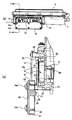
- FIG.1 (a) is a whole side view in the state which the cover opened
- FIG.1 (b) is a partial cross section figure.
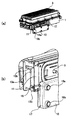
- Fig.2 (a) is a whole perspective view of the state which the cover opened
- FIG.2 (b) is a partial perspective view.
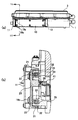
- Fig.3 (a) is a whole side view of the state which the cover closed
- FIG.3 (b) is a partial cross section figure.
- FIG.4 (a) is a whole perspective view of the state which the cover closed
- FIG.4 (b) is a partial perspective view.
- Fig.8 (a) is a whole perspective view in the state with the lid closed
- FIG.8 (b) is a partial perspective view.
- Fig.9 (a) is the whole perspective view of the state which the cover opened
- FIG.9 (b) is a partial perspective view.
- FIG. 1 (a) is an overall side view of the state in which the lid is open (first state)
- FIG. 1 (b) is a view taken along the plane IB-IB in FIG. 1 (a). It is sectional drawing to which the part was expanded.
- FIG. 2A is an overall perspective view with the lid open
- FIG. 2B is an enlarged perspective view of the front corner portion in FIG. 3 (a) is an overall side view of the state in which the lid is closed (second state)
- FIG. 1 (a) is an overall side view of the state in which the lid is closed (second state)
- FIG. 1 (a) is an overall side view of the state in which the lid is closed (second state)
- FIG. 3 (b) is a partial view taken along the line IIIB-IIIB in FIG. 3 (a).
- FIG. 4A is an overall perspective view in a state where the lid is closed
- FIG. 4B is an enlarged perspective view of the front corner portion in FIG. 4A.
- reference numeral 1 denotes a base station device casing
- 3 denotes fins installed on the upper surface of the base station device.
- the housing 1 has a work area (construction area) 8 that is installed on one side surface parallel to the longitudinal direction of the base station apparatus and on which a maintenance worker or a construction worker works.
- reference numeral 10 denotes a lid of the work area 8, and the opening / closing mechanism of the lid 10 is in a state where the work area 8 is opened (first state) and a state where the work area 8 is closed (second state). ) To move the lid 10.
- two work areas are provided for a set of one lid 10 and an opening / closing mechanism for the lid 10.
- one or three or more work areas may be provided for one lid 10 and a set of opening / closing mechanisms of the lid 10. Further, the surface on which the work area is installed may be provided on any surface of the housing 1 depending on the orientation when the base station device is attached outdoors.
- the housing 1 includes a first projection 32 and a second projection 33 on the housing side that run parallel to surround the work area 8, and a first projection 32 and a second projection. 33 has a gasket 35 installed in the groove 31 formed by 33.
- the housing 1 is mounted with various connector terminals, power supply terminals, and the like in the work area 8 (not identified in the figure).
- Various circuit boards are arranged on the inner side of the apparatus with respect to the bottom surface 9 of the work area 8 of the housing 1, and a microswitch 41 is installed on one of the boards 40.
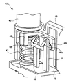
- FIG. 5 shows a perspective view of the micro switch 41 used in the present embodiment.
- the micro switch 41 serves as an open / close sensor for the lid 10 that detects whether or not the lid 10 is fixed to the housing 1 and is completely closed.
- An elastic force by the elastic member 47 is acting on the movable portion 45 at the upper part of the micro switch 41.
- the clip-shaped contact portions 48a and 48b are located between the first terminal 51 and the second terminal 52 as shown in FIG.
- the micro switch 41 is in the off state (first switch state) without conducting the.
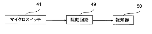
- the first terminal 51 and the second terminal 52 are connected to the drive circuit 49 of the alarm as shown in FIG.
- the drive circuit 49 drives the alarm 50 when the micro switch 41 is in the on state (second switch state), and drives the alarm 50 when the micro switch 41 is in the off state (first switch state).
- a warning sound is emitted from.
- the microswitch 41 is installed in each of the two work areas, and any one of the two microswitches 41 is in an off state (first state). An alarm is notified at the time of switch state.
- the movable portion 45 of the micro switch 41 is installed at a position exposed to the work area 8 through a hole opened in the bottom surface 9 of the work area 8 as shown in FIG. That is, the second protrusion 26 of the lid 10 contacts the upper surface of the movable portion 45 of the microswitch 41 through this hole, and pushes the movable portion 45 downward when the lid 10 is fixed to the housing 1. .
- the lid 10 is disposed so as to face the gasket 35, and faces the first projecting portion (contact portion) 22 that contacts the gasket 35 and the movable portion 45 of the microswitch 41 when the lid 10 is closed.
- the second protrusion 26 is in contact with the movable portion 45, the reinforcing portion 25 reinforces the strength of the second protrusion 26, and the outer peripheral portion 21.
- the outer peripheral portion 21 is not essential as a constituent requirement of the present embodiment, but deformation such as warpage of the lid 10 can be suppressed by adopting a structure including the outer peripheral portion 21.
- the double structure of the outer peripheral portion 21 and the first protruding portion 22 can further improve the sealing performance, and further functions as a guide for guiding the first protruding portion 22 to the groove portion 31 on the working area 8 side.
- the reinforcing portion 25 is appropriately provided when the second projecting portion 26 needs to be reinforced.
- the base station apparatus includes a first movable mechanism, a second movable mechanism, and a fixed member as an opening / closing mechanism for the lid 10.
- the first movable mechanism is embodied by the first guide member 11, the portion 13 a of the second guide member 13 arranged in parallel with the first guide member 11, and the engaging member 15 of the lid 10. Is done.
- the first movable mechanism is a state in which the lid 10 is opened by moving the engaging member 15 of the lid 10 in the vertical direction in FIG. 2B in the space formed by the first guide member 11 and the second guide member 13a.
- the third state that is a predetermined distance in the direction perpendicular to the installation surface of the work area 8 from the state in which the lid 10 is closed can be reversibly moved.
- the first guide member 11 is fixed to the housing 1 via an attachment member, and the predetermined distance in the third state is determined by the attachment height of the first guide member 11. It will be.
- the second movable mechanism is embodied by a portion 13 b of the second guide member 13 that is arranged perpendicular to the first guide member 11 and the engaging member 15 of the lid 10.
- the engagement member 15 of the lid 10 moves along the second guide member 13b in a space formed by the second guide member 13b and the portion of the housing 1, so that the lid 10 is closed.
- the lid 10 can be reversibly moved between the third state and the third state.
- the first guide member 11 and the second guide member portion 13a are arranged perpendicular to the second guide member 13 portion 13b, but the first guide member 11 and the second guide member portion 13a. Is not limited to being vertical as long as it is disposed obliquely with an angle with respect to the portion 13 b of the second guide member 13. It is designed appropriately depending on the direction in which the lid 10 opens.
- the fixing member includes mounting screws 19a, 19b... On the upper surface of the lid 10.
- the lid 10 can be fixed by applying a force to the lid 10 in a direction perpendicular to the installation surface of the work area 8 when the lid 10 is closed.
- the lid 10 may be temporarily fixed with a stopper or the like. By doing so, it is possible to prevent the lid 10 from being dropped or displaced.
- the lid 10 is fixed and completely closed (see FIGS. 3 and 3) from the state in which the lid 10 is opened (see FIGS. 1 and 2).
- the fixing member that fixes the lid 10 is not limited to the mounting screws 19a and 19b.
- the lid 10 may be fixed to the casing 1 by providing the casing 1 with an engaging portion that engages with the lid 10 in a state where the lid 10 is completely closed.
- the work area 8 is installed on one surface of the housing 1 of the base station apparatus, and the work area 8 is opened by the opening / closing mechanism of the lid 10.
- the base station apparatus moves the lid 10 between the closed state and the casing 1, and the housing 1 includes a gasket 35 installed so as to surround the work area 8, and the lid 10 faces the gasket 35.
- the lid 10 is in a closed state, the first projection 22 is in contact with the gasket 35. Further, as an opening / closing mechanism of the lid 10, the lid 10 is opened and the lid 10 is closed.
- a first movable mechanism for reversibly moving between a third state at a predetermined distance in a direction perpendicular to the area 8 installation surface, a state in which the lid 10 is closed, and a third state of the lid 10 A second movable mechanism that reversibly moves between the states of In a state where the lid is closed, by applying a force in a direction perpendicular to the working area 8 installation surface on the cover 10, a fixing member for fixing the lid 10 (the mounting screw 19a, 19b, ...) and, a configuration having a.
- the second movable mechanism moves from the third state of the lid 10 to the closed state of the lid 10 along the direction perpendicular to the installation surface of the work area 8, and is fixed by the fixing member.
- the gasket 35 is compressed by applying a vertical force to the gasket 35. For this reason, the variation in the compression amount of the gasket 35 can be suppressed, and as a result, a waterproof structure having higher sealing performance at a lower cost can be realized.
- the chassis 1 is installed at a predetermined position in the work area 8, and is turned off when the movable portion 45 is pushed down in a direction perpendicular to the work area 8 installation surface (first switch state).
- the microswitch 41 is switched from ON to the second switch state (the second switch state), and the lid 10 is disposed to face the movable portion 45 of the microswitch 41.
- the lid 10 contacts the movable portion 45.
- Two protrusions 26 are provided.
- the opening / closing judgment of the lid 10 by the micro switch 41 will be considered.
- the mounting screw 19 is turned with a specified torque, and the gasket 35 is compressed on the first protrusion 22 by applying a force in a direction perpendicular to the work area 8 installation surface.
- the micro switch 41 transitions from the off state to the on state. Therefore, in the process of fastening the mounting screw 19, the micro switch 41 to be used is the same as the micro switch 41 to be used in a state in which the first protrusion 22 compresses the gasket 35 to ensure the sealing property. It is necessary to transition from the off state to the on state.
- the variation in the ON state is smaller than that of other switches, but has a tolerance that cannot be ignored.
- the tolerance of other members since the tolerance of other members, the tolerance of the members themselves, and assembly errors are added to this, the position where the microswitch 41 is turned on greatly fluctuates.
- the gasket 35 itself also varies in compression amount due to tolerances of other members, tolerances of the members themselves, assembly errors, and the like.
- the compression amount R of the gasket 35 in consideration of the variation P of the position where the microswitch 41 is turned on and the variation Q of the gasket 35. If the above-mentioned points are not taken into account, for example, as shown in FIG. 7A, when the position where a certain microswitch 41 is turned on is the S point, it is influenced by the variation in the compression amount of the gasket 35. In some cases, the movable portion 45 cannot be pushed down to the point S. In this case, even if the lid 10 is closed and has a sealing property, the microswitch 41 does not transition from the off state to the on state, and the microswitch 41 does not correctly determine whether the lid 10 is opened or closed.
- the compression amount in the gasket 35 to be used is determined from the variation P in the position where the microswitch 41 is turned on and the variation amount Q in the compression amount in the gasket 35.
- P is a value calculated from a stacking tolerance calculated by averaging each tolerance generated by a tolerance of other members, a tolerance of the member itself, an assembly error, and the like, and a variation based on processing accuracy.
- Q is a value calculated from a stacking tolerance calculated by averaging each tolerance generated by a tolerance of another member, a tolerance of the member itself, an assembly error, and the like, and a variation based on processing accuracy.
- the minimum value of the maximum width that the movable part 45 can push down in the direction perpendicular to the installation surface of the work area 8 is set to be equal to or greater than the width Z of the compression amount of the gasket 35 described above.
- the movable part 45 is installed in the work area 8.
- the lid 10 can be opened and closed more accurately in this way, if the maintenance worker forgets to close the lid 10 or forgets to fasten the mounting screws 19a, 19b. Even if it gradually loosens, an alarm can be issued when the designed waterproof line is exceeded.
- the lid 10 is moved along the guide by the first movable mechanism and the second movable mechanism, so that it is not possible for the operator to close the lid 10 by force during the operation of closing the lid 10. As a result, breakage of the lid 10 can be prevented.
- the first movable mechanism and the second movable mechanism are provided on both sides of the lid 10, but by changing the hinge cross-sectional shape of both the lid 10, the work area 8 is installed from a fixed position. It is possible to make the structure closed in a direction perpendicular to the surface.
- FIG.8 and FIG.9 is a block diagram of the base station apparatus which concerns on 2nd Embodiment of this invention.
- FIG. 8A is an overall perspective view in a state where the lid is opened (first state)
- FIG. 8B is an enlarged perspective view of the upper left corner portion in FIG. 8A
- FIG. 9A is an overall perspective view in a state where the lid is closed (second state)
- FIG. 9B is an enlarged perspective view of the upper left corner portion in FIG. 9A.
- reference numeral 101 denotes a base station apparatus casing.
- work areas where maintenance workers or construction workers work are installed on the upper and lower surfaces parallel to the longitudinal direction of the base station apparatus.
- reference numerals 102 and 103 each denote a lid structure.
- the lid structure 103 the working area is opened (first state) and the working area is closed (first state) by the opening / closing mechanism of the lid 110 ( Second state).
- Second state the opening / closing mechanism of the lid 110
- This embodiment is different from the first embodiment in that the first movable mechanism of the lid opening / closing mechanism is the slide method in the first embodiment, whereas the rotation method is used in the present embodiment. is there.
- the other lid opening / closing mechanism is the same as that of the first embodiment, and the structure of the back side of the lid and the structure of the work area are the same as those of the first embodiment except for the shape.
- the first movable mechanism of the present embodiment includes a first guide member 112 (112a and 112b), a second guide member 113 (113a, 113b and 113c), and an engaging member 115 of the lid 110.
- the engaging member 115 of the lid 110 is moved in the space (guide opening) formed by the first guide member 112 and the second guide member 113, and the lid 110 is rotated about the short side direction of the housing 101 as an axis.
- the lid 10 can be moved to the opened state, the third state, and the closed state with a simple structure.
- the lid 110 moves from the third state to the closed state along the direction perpendicular to the work area installation surface. For this reason, variation in the compression amount of the gasket can be suppressed, and as a result, a waterproof structure having higher sealing performance at a lower cost can be realized. In addition, since the variation in the compression amount of the gasket is suppressed, the opening / closing judgment of the lid 110 by the microswitch can be performed more accurately.
- the lid 10 is provided for the work area 8 of the base station apparatus.
- the base station apparatus has an opening, and a waterproof structure in which the opening is sealed with the lid. You may need it.
- the waterproof structure of the above embodiment can be applied not only to the work area 8 but also to the opening of such a base station apparatus.
- the lid 110 is rotated about the short side direction of the housing 101 by the first movable mechanism, but may be configured to rotate about the long side direction of the housing 101. .
- the present invention is suitably used for a base station apparatus that requires a waterproof structure.
Landscapes
- Engineering & Computer Science (AREA)
- Microelectronics & Electronic Packaging (AREA)
- Computer Networks & Wireless Communication (AREA)
- Signal Processing (AREA)
- Casings For Electric Apparatus (AREA)
Abstract
開口を有する筐体(1)と、蓋(10)と、前記開口を開いた第1の状態と前記開口を閉じた第2の状態との間で前記蓋を移動させる開閉機構とを備え、前記筐体は前記開口の周囲にガスケットを備え、前記蓋は前記ガスケットに当接する当接部を備え、前記開閉機構は、当該蓋の前記第1の状態と、該蓋の前記第2の状態から前記開口の開口面に垂直な方向に所定距離にある第3の状態と、の状態間を可逆的に移動させる第1可動機構(11,13a,15)と、当該蓋の前記第2の状態と、該蓋の第3の状態と、の状態間を可逆的に移動させる第2可動機構(13b,15)と、当該蓋が前記第2の状態において、該蓋に対し開口面に垂直な方向に力を加えて、該蓋を固定する固定部材(19a,19b)と、を有する基地局装置。
Description
本発明は、高い密閉性を持つ防水構造を備えた基地局装置および蓋の取り付け方法に関する。
移動通信の発展に伴って、基地局装置の数も増加し、各所に基地局装置が設置されている。このような基地局装置は、一般に屋外に設置されることから、様々な設置環境に対しても耐久性を維持できるよう、装置構造に種々の工夫がなされている。また、基地局装置は、定期的な保守・点検、並びにそれに伴う交換・増設作業などが必要である。このため、保守・点検作業や交換・増設作業を行い易くするための構造上の工夫も種々提案されている(例えば、日本国・特開2006-135368参照)。
基地局装置では、このような保守・点検作業をスムーズに行うため、保守・点検作業に必要なコネクタ端子や電源端子などを一箇所に集めて、これらを配置した作業領域(または工事領域)を設けている。また、この作業領域に対して蓋を取り付けて、蓋の開閉により作業空間の露出/密閉を行うことが可能な構造としている。特に、基地局装置は電子機器であることから、高い密閉性を持つ防水構造が重要である。また、上記作業領域に限らずとも、基地局装置の筺体に開口および、開口に対して開閉可能な蓋を設けた構成において、装置内部を外部から遮断する為に、この開口の高い密閉性を持つ防水構造を必要とする場合がある。
従来の技術では、基地局装置における装置内部と作業領域(工事領域)または開口を完全に遮断するために、コネクタ端子や電源端子などを載置した基板全体を樹脂等で覆ったターミナル基板のような別部材を用いていた。このように構成することで、該ターミナル基板及び蓋による2重防水の構造として、保守作業者または工事作業者が蓋を閉め忘れた場合であっても、装置内部が浸水して基地局装置が壊れない構造であった。
しかしながら、上述した従来の技術で用いていたターミナル基板は、防水機能を備えると共に、装置メンテナンスに使用するコネクタ端子類も搭載されていた。このため、全体が防水構造となっていなければならず、非常に高価なものとなって、機構材料費の多くを占めていた。
本発明は、上記従来の事情に鑑みてなされたものであって、より低コストで高い密閉性を持つ防水構造を実現する基地局装置および、蓋の取り付け方法を提供することを一の目的としている。
本願発明の一態様に係る基地局装置は、開口を有する筺体と、蓋と、前記開口を開いた第1の状態と前記開口を閉じた第2の状態との間で前記蓋を移動させる開閉機構とを備え、前記筺体は前記開口の周囲にガスケットを備え、前記蓋は前記ガスケットに当接する当接部を備え、前記開閉機構は、当該蓋の前記第1の状態と、該蓋の前記第2の状態から前記開口の開口面に垂直な方向に所定距離にある第3の状態と、の状態間を可逆的に移動させる第1可動機構と、当該蓋の前記第2の状態と、該蓋の前記第3の状態と、の状態間を可逆的に移動させる第2可動機構と、当該蓋が前記第2の状態において、該蓋に開口面に垂直な方向に力を加えて、該蓋を固定する固定部材と、を有する。
なお、上記基地局装置において、前記筺体は前記開口の周囲を囲み平行に延びる第1突起部および第2突起部を有し、前記ガスケットは前記第1突起部と前記第2突起部の間に設置してもよい。
また、上記基地局装置において、前記当接部は前記蓋に設けられた突起部であり、前記第2の状態において前記ガスケットに接してもよい。
また、上記基地局装置において、前記筺体は前記開口面に垂直に延びる垂直ガイドおよび、前記垂直ガイドと接続し前記垂直ガイドから所定の角度で延びる斜めガイドを有し、前記蓋は前記垂直ガイドと前記斜めガイドに沿って移動可能な係部材を有してもよい。この際、前記斜めガイドと前記係部材が前記第1可動機構を構成し、前記垂直ガイドと前記係部材が前記第2可動機構を構成してもよい。
また、上記基地局装置において、前記開口は前記筺体の側面に設けられていてもよい。
また、上記基地局装置において、前記筺体はコネクタ端子を含む回路基板を有し、前記コネクタ端子は前記開口に露出してもよい。
本願発明の別の態様に係る基地局装置は、一の面に作業領域を有する筺体と、蓋と、前記作業領域を開いた第1の状態と前記作業領域を閉じた第2の状態との間で、前記蓋を移動する開閉機構と、警報を報知する報知部と、を備えた基地局装置であって、前記筺体は、当該作業領域を囲むように設置されたガスケットと、当該作業領域の所定位置に設置され、作業領域設置面に垂直な方向に押し下げられることにより第1スイッチ状態から第2スイッチ状態へ遷移する可動部を備えるスイッチと、を有し、前記蓋は、前記ガスケットに対向して配置され、当該蓋が前記第2の状態のときに、該ガスケットと接する第1突起部と、前記スイッチの可動部に対向して配置され、当該蓋が前記第2の状態のときに、該可動部と接する第2突起部と、を有し、前記開閉機構は、当該蓋が前記第1の状態と、該蓋が前記第2の状態から作業領域設置面に垂直な方向に所定距離にある第3の状態と、の状態間を可逆的に移動させる第1可動機構と、当該蓋が前記第2の状態と、該蓋の前記第3の状態と、の状態間を可逆的に移動させる第2可動機構と、当該蓋が前記第2の状態において、該蓋に作業領域設置面に垂直な方向に力を加えて、該蓋を固定する固定部材と、を有し、前記報知部は、前記スイッチが前記第1スイッチ状態の時に警報を報知する。
なお、上記基地局装置において、1つの蓋及び該蓋の開閉機構の組に対して複数の作業領域が設置され、前記報知部は、複数のスイッチの内の何れかのスイッチが前記第1スイッチ状態の時に警報を報知してもよい。
また、上記基地局装置において、前記筺体は、前記作業領域の周囲を囲む平行な第1突起部および第2突起部を有し、前記ガスケットは前記第1突起部と前記第2突起部の間に設置されてもよい。
また、上記基地局装置において、前記第1可動機構は、前記蓋を一の方向にスライドさせるスライド機構を有してもよい。
また、上記基地局装置において、前記第1可動機構は、前記蓋を一の方向に回転させる回転機構を有してもよい。
また、上記基地局装置において、前記第1可動機構は、前記作業領域設置面に平行に設けられたガイド部および、前記蓋に設けられた係部材によって構成され、前記係部材が前記ガイド部に沿って移動することにより、前記蓋が前記第1の状態と前記第3の状態との状態間を移動してもよい。
また、上記基地局装置において、前記第2可動機構は、前記作業領域設置面に垂直に設けられたガイド部および、前記蓋に設けられた係部材によって構成され、前記係部材が前記ガイド部に沿って移動することにより、前記蓋が前記第2の状態と、前記第3の状態との状態間を移動してもよい。
また、上記基地局装置において、前記第1可動機構は、前記作業領域に隣接して設けられたガイド開口と、前記蓋に設けられた係部材によって構成され、前記係部材は前記ガイド開口の回動可能に挿入され、前記係部材が前記ガイドの中で回動することにより、前記蓋が前記第1の状態と前記第3の状態との状態間を移動してもよい。
また、上記基地局装置において、前記第2可動機構は、前記作業領域設置面に垂直に設けられたガイド部および、前記蓋に設けられた係部材によって構成され、前記係部材が前記ガイド部に沿って移動することにより、前記蓋が前記第2の状態と、前記第3の状態との状態間を移動してもよい。
また、上記基地局装置において、前記固定部材はネジであってもよい。
また、上記基地局装置において、前記作業領域が設置された面は、前記筺体の側面でもよい。
本願発明の別の態様に係る蓋の取り付け方法は、開口および開口の周囲にガスケットを有する筺体と、蓋と、前記開口を開いた第1の状態と前記開口を閉じた第2の状態との間で前記蓋を移動させる開閉機構とを備える基地局装置における、前記蓋の取り付け方法であって、前記開閉機構によって、前記蓋を前記第1の状態から、該蓋が前記第2の状態から開口の開口面に垂直な方向に所定距離にある第3の状態へ移動させ、前記開閉機構によって、前記蓋を前記第3の状態から前記第2の状態へ移動させ、当該蓋の前記第2の状態において、該蓋に開口面に垂直な方向に力を加えて、該蓋を固定する。
上記基地局装置および蓋の取り付け方法によれば、蓋の第3の状態から蓋が閉じた第2の状態へ開口面または作業領域設置面に垂直な方向に沿って移動するので、ガスケットの圧縮量のバラツキを抑えることができ、結果として、より低コストで高い密閉性を持つ防水構造を実現することができる。
以下、本発明の基地局装置の実施形態について、第1実施形態、第2実施形態の順に図面を参照して詳細に説明する。
〔第1実施形態〕
図1~図4は本発明の第1実施形態に係る基地局装置の構成図である。ここで、図1(a)は蓋が開いた状態(第1の状態)の全体側面図であり、図1(b)は図1(a)におけるIB-IBの面で切ったときの一部を拡大した断面図である。また、図2(a)は蓋が開いた状態の全体斜視図であり、図2(b)は図2(a)において手前角部分を拡大した斜視図である。また、図3(a)は蓋が閉じた状態(第2の状態)の全体側面図であり、図3(b)は図3(a)におけるIIIB-IIIBの面で切ったときの一部を拡大した断面図である。また、図4(a)は蓋が閉じた状態の全体斜視図であり、図4(b)は図4(a)において手前角部分を拡大した斜視図である。
〔第1実施形態〕
図1~図4は本発明の第1実施形態に係る基地局装置の構成図である。ここで、図1(a)は蓋が開いた状態(第1の状態)の全体側面図であり、図1(b)は図1(a)におけるIB-IBの面で切ったときの一部を拡大した断面図である。また、図2(a)は蓋が開いた状態の全体斜視図であり、図2(b)は図2(a)において手前角部分を拡大した斜視図である。また、図3(a)は蓋が閉じた状態(第2の状態)の全体側面図であり、図3(b)は図3(a)におけるIIIB-IIIBの面で切ったときの一部を拡大した断面図である。また、図4(a)は蓋が閉じた状態の全体斜視図であり、図4(b)は図4(a)において手前角部分を拡大した斜視図である。
図1~図4において、1は基地局装置の筐体であり、3は基地局装置の上面に設置されているフィンである。筺体1は、基地局装置の長手方向に平行な一方の側面に設置された、保守作業者または工事作業者が作業する作業領域(工事領域)8を有する。また、図中、10は該作業領域8の蓋であり、蓋10の開閉機構は、作業領域8を開いた状態(第1の状態)と、作業領域8を閉じた状態(第2の状態)との間で蓋10を移動する。なお、本実施形態では、1つの蓋10及び該蓋10の開閉機構の組に対して2つの作業領域が設置されている。なお、1つの蓋10及び該蓋10の開閉機構の組に対して1つまたは3つ以上の作業領域が設置されてもよい。また、作業領域が設置された面は、基地局装置を屋外に取り付ける際の向きによって、筺体1のどの面に設けられてもよい。
筺体1は、図1(b)に示す如く、作業領域8の周囲を囲むようにして平行に走る筐体側の第1突起部32及び第2突起部33と、第1突起部32及び第2突起部33によって形成される溝部31に設置されたガスケット35を有する。また、筺体1は、作業領域8に、各種コネクタ端子や電源端子等が搭載されている(図では識別せず)。また、筺体1の作業領域8の底面9よりも装置内部側には、各種回路基板が配置されており、その内の一の基板40にマイクロスイッチ41が設置されている。
本実施形態で使用するマイクロスイッチ41の斜視図を図5に示す。このマイクロスイッチ41は、蓋10が筐体1に固定されて完全に閉じた状態にあるか否かを検知する蓋10の開閉センサの役割を果たしている。マイクロスイッチ41の上部にある可動部45には、弾性部材47による弾性力が働いている。可動部45に対して下方に向かう力が掛かっていない蓋10が開いた状態では、図5に示す状態にあって、クリップ状の接点部48a及び48bは第1端子51及び第2端子52間を導通させることなく、マイクロスイッチ41はオフ状態(第1スイッチ状態)にある。また、蓋10が開いた状態で、さらに蓋10が筐体1に固定されると、可動部45に対して下方に向かう力が働き、連結部46を介して接点部48a及び48bも連動して下方に向かって摺動し、第1端子51及び第2端子52間を導通させて、マイクロスイッチ41をオン状態(第2スイッチ状態)にする。
第1端子51及び第2端子52は、図6に示す如く報知器の駆動回路49に接続されている。駆動回路49はマイクロスイッチ41がオン状態(第2スイッチ状態)のときには報知器50を駆動し、またマイクロスイッチ41がオフ状態(第1スイッチ状態)のときには報知器50を駆動し、報知器50から警報音等を発する。なお、より具体的には、本実施形態では、2つの作業領域にそれぞれマイクロスイッチ41が設置されており、2つのマイクロスイッチ41の内の何れかの一方のマイクロスイッチ41がオフ状態(第1スイッチ状態)の時に警報が報知される。
なお、マイクロスイッチ41の可動部45は、図1(b)に示す如く、作業領域8の底面9に明けられた穴を介して作業領域8に露出した位置に設置されている。つまり、蓋10の第2突起部26は、この穴を介してマイクロスイッチ41の可動部45上面と接触し、蓋10が筐体1に固定される際には、可動部45を下方に押す。
蓋10は、ガスケット35に対向して配置され、蓋10が閉じた状態のときに、ガスケット35と接する第1突起部(当接部)22と、マイクロスイッチ41の可動部45に対向して配置され、蓋10が閉じた状態のときに、該可動部45と接する第2突起部26と、第2突起部26の強度を補強する補強部25と、外周部21と、を備えている。なお、本実施例の構成要件としては、外周部21は必須ではないが、外周部21を備えた構造とすることにより、蓋10の反りなどの変形を抑えることができる。また、外周部21および第1突起部22の2重構造により、より密閉性を高めることができ、さらに、第1突起部22を作業領域8側の溝部31に導くガイドとしても機能する。また、補強部25は第2突起部26の補強が必要な場合に適宜設けられる。
また、基地局装置は蓋10の開閉機構として、第1可動機構、第2可動機構及び固定部材を備える。第1可動機構は、図2(b)に示す如く、第1ガイド部材11、第2ガイド部材13の内の第1ガイド部材11と並行配置された部分13a及び蓋10の係部材15によって具現される。第1可動機構は、蓋10の係部材15が第1ガイド部材11と第2ガイド部材13aによって形成される空間を図2(b)において上下方向に移動することで、蓋10が開いた状態と、蓋10が閉じた状態から作業領域8設置面に垂直な方向に所定距離にある第3の状態と、の状態間を可逆的に移動させることができる。なお、図1(b)に示す如く、第1ガイド部材11は取付部材を介して筐体1に固定されるが、この第1ガイド部材11の取付高さによって第3状態の所定距離が決まることになる。
また、第2可動機構は、図2(b)に示す如く、第2ガイド部材13の内の第1ガイド部材11と垂直配置された部分13b及び蓋10の係部材15によって具現される。第2可動機構は、蓋10の係部材15が第2ガイド部材13bと筐体1の部分によって形成される空間を第2ガイド部材13bに沿って移動することで、蓋10が閉じた状態と、蓋10の第3の状態と、の状態間を可逆的に移動させることができる。このように第1可動機構、第2可動機構を構成することにより、シンプルな構造で蓋10を開いた状態、第3の状態、閉じた状態に移動することができる。
なお、第1ガイド部材11と第2ガイド部材の部分13aは、第2ガイド部材13の部分13bに対して垂直に配置されているが、この第1ガイド部材11と第2ガイド部材の部分13aは第2ガイド部材13の部分13bに対して角度を有して斜めに配置されていれば垂直に限らない。蓋10の開く方向によって適宜設計される。
また、固定部材は、蓋10の上面にある取付ネジ19a、19b…を含む。この取付ネジ19a、19b、…を規定トルクで回すことにより、蓋10が閉じた状態において、蓋10に作業領域8設置面に垂直な方向に力を加えて、該蓋を固定することができる。なお、蓋10が第3の状態にあるとき、蓋10をストッパー等で仮止めする構造としても良い。こうすることで、蓋10の落下や位置ずれを防ぐことができる。以上の第1可動機構、第2可動機構及び固定部材による一連の動作により、蓋10が開いた状態(図1及び図2参照)から蓋10が固定されて完全に閉じた状態(図3及び図4参照)に移行することができる。なお、蓋10を開ける際には、上述した流れの逆を辿れば良い。なお、蓋10を固定する固定部材は取付ネジ19a、19bに限らない。例えば、筺体1に、蓋10が完全に閉じた状態で蓋10に係合する係合部を設けることによって、蓋10を筺体1に固定してもよい。
以上説明したように、本実施形態の基地局装置では、基地局装置の筺体1の一の面に作業領域8が設置され、蓋10の開閉機構によって作業領域8を開いた状態と作業領域8を閉じた状態との間で、蓋10を移動する基地局装置であって、筺体1は、作業領域8を囲むように設置されたガスケット35を備え、また蓋10は、ガスケット35に対向して配置され、蓋10が閉じた状態のときに、ガスケット35と接する第1突起部22を備え、さらに蓋10の開閉機構として、蓋10が開いた状態と、蓋10が閉じた状態から作業領域8設置面に垂直な方向に所定距離にある第3の状態と、の状態間を可逆的に移動させる第1可動機構と、蓋10が閉じた状態と、蓋10の第3の状態と、の状態間を可逆的に移動させる第2可動機構と、10蓋が閉じた状態において、蓋10に作業領域8設置面に垂直な方向に力を加えて、蓋10を固定する固定部材(取付ネジ19a、19b、…)と、を備えた構成とする。
このように、上記構成では、高価な部品や部材を用いていない。また、第2可動機構により、蓋10の第3の状態から蓋10が閉じた状態へ作業領域8設置面に垂直な方向に沿って移動して、固定部材によって固定し、第1突起部22からガスケット35に対して垂直方向の力を加えて、ガスケット35を圧縮する。このため、ガスケット35の圧縮量のバラツキを抑えることができ、結果として、より低コストで高い密閉性を持つ防水構造を実現することができる。
さらに、本実施形態の基地局装置において、筺体1は、作業領域8の所定位置に設置され、可動部45が作業領域8設置面に垂直な方向に押し下げられることによりオフ(第1スイッチ状態)からオン(第2スイッチ状態)へ遷移するマイクロスイッチ41を備え、蓋10はマイクロスイッチ41の可動部45に対向して配置され、蓋10が閉じた状態のときに、可動部45と接する第2突起部26を備える。
ここで、マイクロスイッチ41による蓋10の開閉判断について考察する。本実施形態では、蓋10を固定する際、取付ネジ19を規定のトルクで回し、作業領域8設置面に垂直な方向に力を加えていくことで、第1突起部22にガスケット35を圧縮させるとともに、第2突起部26がマイクロスイッチ41の可動部45を押すことで、マイクロスイッチ41は、オフ状態からオン状態に遷移する。そのため、使用するマイクロスイッチ41は、取付ネジ19を締結していく過程において、第1突起部22がガスケット35を圧縮し、密閉性を確保できるようになった状態で、使用するマイクロスイッチ41をオフ状態からオン状態に遷移させる必要がある。
しかしながら、本実施形態で使用するマイクロスイッチ41では、オン状態になる位置のバラツキは他のスイッチに比べても小さいものであるが、無視できない公差を持つ。また、これに他の部材の公差、部材自体の公差、組み立て誤差が加わるため、マイクロスイッチ41がオン状態になる位置は大きく変動することになる。また、ガスケット35自体も、他の部材の公差、部材自体の公差、組み立て誤差などにより、圧縮量のバラツキが生じる。
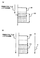
そのため、マイクロスイッチ41におけるオン状態になる位置のバラツキPと、ガスケット35におけるバラツキQと、を考慮した上で、ガスケット35の圧縮量Rを設定する必要がある。なお、上述する点を考慮しなければ、例えば、図7(a)に示すように、あるマイクロスイッチ41のオン状態になる位置がS点である場合、ガスケット35の圧縮量のバラツキの影響によっては、可動部45をこのS点まで押し下げることができない場合が生じる。この場合、蓋10が閉まり、密閉性を有していたとしても、マイクロスイッチ41がオフ状態からオン状態に遷移せず、マイクロスイッチ41による蓋10の開閉判断が正しく行われない。
そこで、本実施形態では、図7(b)に示すように、マイクロスイッチ41のオン状態になる位置のバラツキPと、ガスケット35における圧縮量のバラツキQと、から、使用するガスケット35における圧縮量の幅Rを、R≧2|P|+2|Q|になるよう設定する。ここで、Pは、他の部材の公差、部材自体の公差、組み立て誤差などにより生じる各公差を二乗平均して算出した積み上げ公差と、加工精度に基づくバラツキと、から算出された値である。また、Qは、他の部材の公差、部材自体の公差、組み立て誤差などにより生じる各公差を二乗平均して算出した積み上げ公差と、加工精度に基づくバラツキと、から算出された値である。
さらに、本実施形態では、可動部45が作業領域8設置面に垂直な方向に押し下げることができる最大幅の最小値を、上述するガスケット35の圧縮量の幅Z以上に設定する。例えば、最大幅の最小値をR(=2|P|+2|Q|)に設定したとすると、ガスケット35における圧縮量のバラツキQが最大であったとしても、可動部45が作業領域8設置面に垂直な方向に押し下げた際、マイクロスイッチ41がオン状態となる位置のバラツキPを考慮した範囲である2|P|内のいずれかの位置でマイクロスイッチ41をオフ状態からオン状態に遷移させることができる。これにより、本実施形態では、ガスケット35に対して垂直方向の力を加えて、ガスケット35を圧縮した際、マイクロスイッチ41による蓋10の開閉判断をより正確に行うことができる。
このように蓋10の開閉判断をより正確に行うことができるので、保守作業者が蓋10を閉め忘れた場合や、取付ネジ19a,19b…を規定のトルクで締結することを忘れて、その後徐々にゆるんでいった場合でも、設計上の防水ラインを超えたときに警報を発することができる。
また、本実施形態では、第1可動機構及び第2可動機構により、ガイドに沿って蓋10の移動が行われるので、蓋10を閉める作業時に、作業者が力任せに蓋10を閉めることが不可能となり、その結果として、蓋10の破損を防止することができる。またさらに、本実施形態では、第1可動機構及び第2可動機構を蓋10の両側に持つ構成であるが、両者のヒンジ断面形状を変えることにより、蓋10を決まった位置から作業領域8設置面に垂直な方向に閉める構造とすることが可能となる。
〔第2実施形態〕
図8及び図9は本発明の第2実施形態に係る基地局装置の構成図である。ここで、図8(a)は蓋が開いた状態(第1の状態)の全体斜視図であり、図8(b)は図8(a)において左上角部分を拡大した斜視図である。また、図9(a)は蓋が閉じた状態(第2の状態)の全体斜視図であり、図9(b)は図9(a)において左上角部分を拡大した斜視図である。
図8及び図9は本発明の第2実施形態に係る基地局装置の構成図である。ここで、図8(a)は蓋が開いた状態(第1の状態)の全体斜視図であり、図8(b)は図8(a)において左上角部分を拡大した斜視図である。また、図9(a)は蓋が閉じた状態(第2の状態)の全体斜視図であり、図9(b)は図9(a)において左上角部分を拡大した斜視図である。
図8及び図9において、101は基地局装置の筐体である。本実施形態の基地局装置においては、保守作業者または工事作業者が作業する作業領域は、基地局装置の長手方向に平行な上面及び下面に設置されている。また、図中、102及び103はそれぞれ蓋構造であり、例えば、蓋構造103の場合、蓋110の開閉機構によって、作業領域を開いた状態(第1の状態)と作業領域を閉じた状態(第2の状態)とする。なお、以下では、蓋構造103についてのみ説明を行う。
本実施形態が第1実施形態と異なる点は、蓋の開閉機構の内の第1可動機構が第1実施形態ではスライド方式であったのに対して、本実施形態では回転方式を用いる点である。その他の蓋の開閉機構は第1実施形態と同等であり、蓋の裏側の構造や作業領域の構造も、形状が異なるだけで基本的構造は第1実施形態と同等である。
図9(b)を参照して、本実施形態の第1可動機構は、第1ガイド部材112(112a及び112b)、第2ガイド部材113(113a、113b及び113c)並びに蓋110の係部材115によって具現される。つまり、蓋110の係部材115を第1ガイド部材112と第2ガイド部材113によって形成される空間内(ガイド開口)で移動させ、蓋110を筐体101の短辺方向を軸として回転させることにより、蓋110が開いた状態と、蓋110が閉じた状態から作業領域設置面に垂直な方向に所定距離にある第3の状態と、の状態間を可逆的に移動させることができる。このように第1可動機構、第2可動機構を構成することにより、シンプルな構造で蓋10を開いた状態、第3の状態、閉じた状態に移動することができる。
本実施形態の基地局装置によれば、第1実施形態と同様に、蓋110は第3の状態から蓋110が閉じた状態へ作業領域設置面に垂直な方向に沿って移動する。このため、ガスケットの圧縮量のバラツキを抑えることができ、結果として、より低コストで高い密閉性を持つ防水構造を実現することができる。また、ガスケットの圧縮量のバラツキが抑えられることにより、マイクロスイッチによる蓋110の開閉判断をより正確に行うことができる。
以上、本発明の実施形態について図面を参照して詳述したが、本発明はこれら実施形態およびその変形に限定されるものではなく、本発明の要旨を逸脱しない範囲の設計変更等があっても本発明に含まれる。
例えば、上記実施形態では、基地局装置の作業領域8に対して蓋10を設ける構成であったが、他にも、基地局装置は開口を有し、この開口を蓋によって密閉する防水構造を必要とする場合がある。上記実施形態の防水構造は、作業領域8だけでなく、このような基地局装置の開口にも適用できる。
また、例えば、第2実施形態では、第1可動機構により、蓋110を筐体101の短辺方向を軸として回転させたが、筐体101の長辺方向を軸として回転させる構成としても良い。
本出願は、2011年3月29日出願の日本特許出願・出願番号2011―071469に基づくものであり、その内容はここに参照として取り込まれる。
本発明は、防水構造を必要とする基地局装置に好適に用いられる。
1,101…基地局装置の筐体、3…フィン、8…作業領域、9…作業領域の底面、10,110…蓋、11,12,111,112…第1ガイド部材、13,14,113,114…第2ガイド部材、15,115…蓋の係部材、19a,19b…取付ネジ、21…外周部、22…蓋の第1突起部、25…補強部,26…蓋の第2突起部、32…第1突起部、33…第2突起部、35…ガスケット、40…基板、41…マイクロスイッチ、45…可動部、49…駆動回路、50…報知器、102,103…蓋構造
Claims (18)
- 開口を有する筺体と、
蓋と、
前記開口を開いた第1の状態と前記開口を閉じた第2の状態との間で前記蓋を移動させる開閉機構とを備え、
前記筺体は前記開口の周囲にガスケットを備え、
前記蓋は前記ガスケットに当接する当接部を備え、
前記開閉機構は、
当該蓋の前記第1の状態と、該蓋の前記第2の状態から前記開口の開口面に垂直な方向に所定距離にある第3の状態と、の状態間を可逆的に移動させる第1可動機構と、
当該蓋の前記第2の状態と、該蓋の前記第3の状態と、の状態間を可逆的に移動させる第2可動機構と、
当該蓋が前記第2の状態において、該蓋に開口面に垂直な方向に力を加えて、該蓋を固定する固定部材と、
を有する基地局装置。 - 前記筺体は前記開口の周囲を囲み平行に延びる第1突起部および第2突起部を有し、
前記ガスケットは前記第1突起部と前記第2突起部の間に設置されている、
請求項1に記載の基地局装置。 - 前記当接部は前記蓋に設けられた突起部であり、前記第2の状態において前記ガスケットに接する、
請求項1または請求項2の何れか1項に記載の基地局装置。 - 前記筺体は前記開口面に垂直に延びる垂直ガイドおよび、前記垂直ガイドと接続し前記垂直ガイドから所定の角度で延びる斜めガイドを有し、
前記蓋は前記垂直ガイドと前記斜めガイドに沿って移動可能な係部材を有し、
前記斜めガイドと前記係部材が前記第1可動機構を構成し、
前記垂直ガイドと前記係部材が前記第2可動機構を構成する、
請求項1から請求項3のいずれか1項に記載の基地局装置。 - 前記開口は前記筺体の側面に設けられている、
請求項1から請求項4のいずれか1項に記載の基地局装置。 - 前記筺体はコネクタ端子を含む回路基板を有し、
前記コネクタ端子は前記開口に露出している、
請求項1から請求項5のいずれか1項に記載の基地局装置。 - 一の面に作業領域を有する筺体と、
蓋と、
前記作業領域を開いた第1の状態と前記作業領域を閉じた第2の状態との間で、前記蓋を移動する開閉機構と、
警報を報知する報知部と、を備えた基地局装置であって、
前記筺体は、
当該作業領域を囲むように設置されたガスケットと、
当該作業領域の所定位置に設置され、作業領域設置面に垂直な方向に押し下げられることにより第1スイッチ状態から第2スイッチ状態へ遷移する可動部を備えるスイッチと、 を有し、
前記蓋は、
前記ガスケットに対向して配置され、当該蓋が前記第2の状態のときに、該ガスケットと接する第1突起部と、
前記スイッチの可動部に対向して配置され、当該蓋が前記第2の状態のときに、該可動部と接する第2突起部と、を有し、
前記開閉機構は、
当該蓋が前記第1の状態と、該蓋が前記第2の状態から作業領域設置面に垂直な方向に所定距離にある第3の状態と、の状態間を可逆的に移動させる第1可動機構と、
当該蓋が前記第2の状態と、該蓋の前記第3の状態と、の状態間を可逆的に移動させる第2可動機構と、
当該蓋が前記第2の状態において、該蓋に作業領域設置面に垂直な方向に力を加えて、 該蓋を固定する固定部材と、を有し、
前記報知部は、前記スイッチが前記第1スイッチ状態の時に警報を報知する、基地局装置。 - 1つの蓋及び該蓋の開閉機構の組に対して複数の作業領域が設置され、
前記報知部は、複数のスイッチの内の何れかのスイッチが前記第1スイッチ状態の時に警報を報知する、
請求項7に記載の基地局装置。 - 前記筺体は、前記作業領域の周囲を囲む平行な第1突起部および第2突起部を有し、
前記ガスケットは前記第1突起部と前記第2突起部の間に設置されている、
請求項7または請求項8の何れか1項に記載の基地局装置。 - 前記第1可動機構は、前記蓋を一の方向にスライドさせるスライド機構を有する、
請求項7から請求項9の何れか1項に記載の基地局装置。 - 前記第1可動機構は、前記蓋を一の方向に回転させる回転機構を有する、
請求項7から請求項9の何れか1項に記載の基地局装置。 - 前記第1可動機構は、前記作業領域設置面に平行に設けられたガイド部および、前記蓋に設けられた係部材によって構成され、
前記係部材が前記ガイド部に沿って移動することにより、前記蓋が前記第1の状態と前記第3の状態との状態間を移動する、
請求項7から請求項9の何れか1項に記載の基地局装置。 - 前記第2可動機構は、前記作業領域設置面に垂直に設けられたガイド部および、前記蓋に設けられた係部材によって構成され、
前記係部材が前記ガイド部に沿って移動することにより、前記蓋が前記第2の状態と、 前記第3の状態との状態間を移動する、
請求項12に記載の基地局装置。 - 前記第1可動機構は、前記作業領域に隣接して設けられたガイド開口と、前記蓋に設けられた係部材によって構成され、
前記係部材は前記ガイド開口の回動可能に挿入され、前記係部材が前記ガイドの中で回動することにより、前記蓋が第1の状態と前記第3の状態との状態間を移動する、
請求項7から請求項9の何れか1項に記載の基地局装置。 - 前記第2可動機構は、前記作業領域設置面に垂直に設けられたガイド部および、前記蓋に設けられた係部材によって構成され、
前記係部材が前記ガイド部に沿って移動することにより、前記蓋が前記第2の状態と、前記第3の状態との状態間を移動する、
請求項14に記載の基地局装置。 - 前記固定部材はネジである、
請求項7から請求項15の何れか1項に記載の基地局装置。 - 前記作業領域が設置された面は、前記筺体の側面である、
請求項7から請求項16の何れか1項に記載の基地局装置。 - 開口および開口の周囲にガスケットを有する筺体と、蓋と、前記開口を開いた第1の状態と前記開口を閉じた第2の状態との間で前記蓋を移動させる開閉機構とを備える基地局装置における、前記蓋の取り付け方法であって、
前記開閉機構によって、前記蓋を前記第1の状態から、該蓋が前記第2の状態から開口の開口面に垂直な方向に所定距離にある第3の状態へ移動させ、
前記開閉機構によって、前記蓋を前記第3の状態から前記第2の状態へ移動させ、
当該蓋の前記第2の状態において、該蓋に開口面に垂直な方向に力を加えて、該蓋を固定する、蓋の取り付け方法。
Priority Applications (1)
| Application Number | Priority Date | Filing Date | Title |
|---|---|---|---|
| JP2013507749A JP5640144B2 (ja) | 2011-03-29 | 2012-03-29 | 基地局装置および蓋の取り付け方法 |
Applications Claiming Priority (2)
| Application Number | Priority Date | Filing Date | Title |
|---|---|---|---|
| JP2011-071469 | 2011-03-29 | ||
| JP2011071469 | 2011-03-29 |
Publications (1)
| Publication Number | Publication Date |
|---|---|
| WO2012133702A1 true WO2012133702A1 (ja) | 2012-10-04 |
Family
ID=46931404
Family Applications (1)
| Application Number | Title | Priority Date | Filing Date |
|---|---|---|---|
| PCT/JP2012/058475 Ceased WO2012133702A1 (ja) | 2011-03-29 | 2012-03-29 | 基地局装置および蓋の取り付け方法 |
Country Status (2)
| Country | Link |
|---|---|
| JP (1) | JP5640144B2 (ja) |
| WO (1) | WO2012133702A1 (ja) |
Cited By (3)
| Publication number | Priority date | Publication date | Assignee | Title |
|---|---|---|---|---|
| CN106686930A (zh) * | 2015-11-06 | 2017-05-17 | 青岛海尔滚筒洗衣机有限公司 | 一种防水pcb板盒及具有该板盒的洗衣机 |
| CN113347839A (zh) * | 2021-06-19 | 2021-09-03 | 九江职业技术学院 | 一种抗干扰电子通信装置 |
| JP2025501162A (ja) * | 2022-05-27 | 2025-01-17 | 楽天シンフォニー株式会社 | 通信デバイスのための自己冷却シャーシ |
Citations (8)
| Publication number | Priority date | Publication date | Assignee | Title |
|---|---|---|---|---|
| JPS4940501Y1 (ja) * | 1968-11-21 | 1974-11-07 | ||
| JPH01133789U (ja) * | 1988-03-03 | 1989-09-12 | ||
| JPH114084A (ja) * | 1997-06-12 | 1999-01-06 | Hitachi Ltd | 電子機器用筐体 |
| JP2000049518A (ja) * | 1998-07-30 | 2000-02-18 | Kajima Corp | 電波反射性壁面へのphs基地局アンテナ設置方法及び装置 |
| JP2000049680A (ja) * | 1998-07-30 | 2000-02-18 | Sanyo Electric Co Ltd | 携帯電話システムの基地局ユニット |
| JP2004311660A (ja) * | 2003-04-04 | 2004-11-04 | Hitachi Kokusai Electric Inc | 電子機器の筐体構造 |
| JP2006313853A (ja) * | 2005-05-09 | 2006-11-16 | Fuji Photo Film Co Ltd | 防水構造 |
| JP2010124072A (ja) * | 2008-11-17 | 2010-06-03 | Nec Corp | 筐体の防水機構、筐体組立方法および携帯端末装置 |
-
2012
- 2012-03-29 WO PCT/JP2012/058475 patent/WO2012133702A1/ja not_active Ceased
- 2012-03-29 JP JP2013507749A patent/JP5640144B2/ja not_active Expired - Fee Related
Patent Citations (8)
| Publication number | Priority date | Publication date | Assignee | Title |
|---|---|---|---|---|
| JPS4940501Y1 (ja) * | 1968-11-21 | 1974-11-07 | ||
| JPH01133789U (ja) * | 1988-03-03 | 1989-09-12 | ||
| JPH114084A (ja) * | 1997-06-12 | 1999-01-06 | Hitachi Ltd | 電子機器用筐体 |
| JP2000049518A (ja) * | 1998-07-30 | 2000-02-18 | Kajima Corp | 電波反射性壁面へのphs基地局アンテナ設置方法及び装置 |
| JP2000049680A (ja) * | 1998-07-30 | 2000-02-18 | Sanyo Electric Co Ltd | 携帯電話システムの基地局ユニット |
| JP2004311660A (ja) * | 2003-04-04 | 2004-11-04 | Hitachi Kokusai Electric Inc | 電子機器の筐体構造 |
| JP2006313853A (ja) * | 2005-05-09 | 2006-11-16 | Fuji Photo Film Co Ltd | 防水構造 |
| JP2010124072A (ja) * | 2008-11-17 | 2010-06-03 | Nec Corp | 筐体の防水機構、筐体組立方法および携帯端末装置 |
Cited By (4)
| Publication number | Priority date | Publication date | Assignee | Title |
|---|---|---|---|---|
| CN106686930A (zh) * | 2015-11-06 | 2017-05-17 | 青岛海尔滚筒洗衣机有限公司 | 一种防水pcb板盒及具有该板盒的洗衣机 |
| CN113347839A (zh) * | 2021-06-19 | 2021-09-03 | 九江职业技术学院 | 一种抗干扰电子通信装置 |
| JP2025501162A (ja) * | 2022-05-27 | 2025-01-17 | 楽天シンフォニー株式会社 | 通信デバイスのための自己冷却シャーシ |
| JP7809211B2 (ja) | 2022-05-27 | 2026-01-30 | 楽天シンフォニー株式会社 | 通信デバイスのための自己冷却シャーシ |
Also Published As
| Publication number | Publication date |
|---|---|
| JP5640144B2 (ja) | 2014-12-10 |
| JPWO2012133702A1 (ja) | 2014-07-28 |
Similar Documents
| Publication | Publication Date | Title |
|---|---|---|
| CN100552850C (zh) | 按压开关 | |
| JP5950258B2 (ja) | 電子機器 | |
| US5914460A (en) | Weatherproof enclosure | |
| US8054293B2 (en) | Electronic apparatus | |
| JP5640144B2 (ja) | 基地局装置および蓋の取り付け方法 | |
| EP3739608B1 (en) | Mechanical interlock apparatus, panel assembly and operation assembly for electrical device and electrical device | |
| US8071899B2 (en) | Electronic device with key assembly | |
| JP2014513402A (ja) | 閉鎖近接スイッチ組立体 | |
| KR20040010074A (ko) | 반도체 패키지용 소켓 | |
| WO2010138329A1 (en) | Metering enclosure with specially hinged front cover | |
| CN102165546A (zh) | 紧急止动设备 | |
| CN106814802B (zh) | 可携式电子装置 | |
| JP4841124B2 (ja) | 電子機器およびその製造方法 | |
| KR101099067B1 (ko) | 누름 조작형 스위치장치 | |
| EP3651177B1 (en) | Switch device and opening/closing detection device | |
| CN203895309U (zh) | 开关单元 | |
| JP2005203114A (ja) | キーボタン組立構造 | |
| CN103632877A (zh) | 多方向开关装置 | |
| CN210575665U (zh) | 一种开关装置以及一种电器装置 | |
| JP6830972B2 (ja) | キーボード装置の製造方法、キーボード装置及び電子機器 | |
| CN210156293U (zh) | 一种开关装置以及一种电器装置 | |
| JP2005166333A (ja) | 多方向入力装置 | |
| JP4631507B2 (ja) | 非常通報用ボタン装置 | |
| CN107533937B (zh) | 用于断路器的操作机构的罩壳 | |
| JP5725973B2 (ja) | スライド型電子機器 |
Legal Events
| Date | Code | Title | Description |
|---|---|---|---|
| 121 | Ep: the epo has been informed by wipo that ep was designated in this application |
Ref document number: 12764882 Country of ref document: EP Kind code of ref document: A1 |
|
| ENP | Entry into the national phase |
Ref document number: 2013507749 Country of ref document: JP Kind code of ref document: A |
|
| NENP | Non-entry into the national phase |
Ref country code: DE |
|
| 122 | Ep: pct application non-entry in european phase |
Ref document number: 12764882 Country of ref document: EP Kind code of ref document: A1 |