WO2012133272A1 - 電子機器 - Google Patents
電子機器 Download PDFInfo
- Publication number
- WO2012133272A1 WO2012133272A1 PCT/JP2012/057698 JP2012057698W WO2012133272A1 WO 2012133272 A1 WO2012133272 A1 WO 2012133272A1 JP 2012057698 W JP2012057698 W JP 2012057698W WO 2012133272 A1 WO2012133272 A1 WO 2012133272A1
- Authority
- WO
- WIPO (PCT)
- Prior art keywords
- touch panel
- display
- display screen
- information
- user
- Prior art date
- Legal status (The legal status is an assumption and is not a legal conclusion. Google has not performed a legal analysis and makes no representation as to the accuracy of the status listed.)
- Ceased
Links
Images





Classifications
-
- G—PHYSICS
- G06—COMPUTING OR CALCULATING; COUNTING
- G06F—ELECTRIC DIGITAL DATA PROCESSING
- G06F3/00—Input arrangements for transferring data to be processed into a form capable of being handled by the computer; Output arrangements for transferring data from processing unit to output unit, e.g. interface arrangements
- G06F3/01—Input arrangements or combined input and output arrangements for interaction between user and computer
- G06F3/03—Arrangements for converting the position or the displacement of a member into a coded form
- G06F3/041—Digitisers, e.g. for touch screens or touch pads, characterised by the transducing means
- G06F3/0412—Digitisers structurally integrated in a display
-
- G—PHYSICS
- G06—COMPUTING OR CALCULATING; COUNTING
- G06F—ELECTRIC DIGITAL DATA PROCESSING
- G06F1/00—Details not covered by groups G06F3/00 - G06F13/00 and G06F21/00
- G06F1/16—Constructional details or arrangements
- G06F1/1613—Constructional details or arrangements for portable computers
- G06F1/1615—Constructional details or arrangements for portable computers with several enclosures having relative motions, each enclosure supporting at least one I/O or computing function
-
- G—PHYSICS
- G06—COMPUTING OR CALCULATING; COUNTING
- G06F—ELECTRIC DIGITAL DATA PROCESSING
- G06F3/00—Input arrangements for transferring data to be processed into a form capable of being handled by the computer; Output arrangements for transferring data from processing unit to output unit, e.g. interface arrangements
- G06F3/01—Input arrangements or combined input and output arrangements for interaction between user and computer
- G06F3/048—Interaction techniques based on graphical user interfaces [GUI]
- G06F3/0481—Interaction techniques based on graphical user interfaces [GUI] based on specific properties of the displayed interaction object or a metaphor-based environment, e.g. interaction with desktop elements like windows or icons, or assisted by a cursor's changing behaviour or appearance
- G06F3/0482—Interaction with lists of selectable items, e.g. menus
-
- G—PHYSICS
- G06—COMPUTING OR CALCULATING; COUNTING
- G06F—ELECTRIC DIGITAL DATA PROCESSING
- G06F3/00—Input arrangements for transferring data to be processed into a form capable of being handled by the computer; Output arrangements for transferring data from processing unit to output unit, e.g. interface arrangements
- G06F3/01—Input arrangements or combined input and output arrangements for interaction between user and computer
- G06F3/048—Interaction techniques based on graphical user interfaces [GUI]
- G06F3/0484—Interaction techniques based on graphical user interfaces [GUI] for the control of specific functions or operations, e.g. selecting or manipulating an object, an image or a displayed text element, setting a parameter value or selecting a range
- G06F3/04842—Selection of displayed objects or displayed text elements
-
- G—PHYSICS
- G06—COMPUTING OR CALCULATING; COUNTING
- G06F—ELECTRIC DIGITAL DATA PROCESSING
- G06F3/00—Input arrangements for transferring data to be processed into a form capable of being handled by the computer; Output arrangements for transferring data from processing unit to output unit, e.g. interface arrangements
- G06F3/01—Input arrangements or combined input and output arrangements for interaction between user and computer
- G06F3/048—Interaction techniques based on graphical user interfaces [GUI]
- G06F3/0487—Interaction techniques based on graphical user interfaces [GUI] using specific features provided by the input device, e.g. functions controlled by the rotation of a mouse with dual sensing arrangements, or of the nature of the input device, e.g. tap gestures based on pressure sensed by a digitiser
- G06F3/0488—Interaction techniques based on graphical user interfaces [GUI] using specific features provided by the input device, e.g. functions controlled by the rotation of a mouse with dual sensing arrangements, or of the nature of the input device, e.g. tap gestures based on pressure sensed by a digitiser using a touch-screen or digitiser, e.g. input of commands through traced gestures
-
- G—PHYSICS
- G06—COMPUTING OR CALCULATING; COUNTING
- G06F—ELECTRIC DIGITAL DATA PROCESSING
- G06F3/00—Input arrangements for transferring data to be processed into a form capable of being handled by the computer; Output arrangements for transferring data from processing unit to output unit, e.g. interface arrangements
- G06F3/01—Input arrangements or combined input and output arrangements for interaction between user and computer
- G06F3/048—Interaction techniques based on graphical user interfaces [GUI]
- G06F3/0487—Interaction techniques based on graphical user interfaces [GUI] using specific features provided by the input device, e.g. functions controlled by the rotation of a mouse with dual sensing arrangements, or of the nature of the input device, e.g. tap gestures based on pressure sensed by a digitiser
- G06F3/0488—Interaction techniques based on graphical user interfaces [GUI] using specific features provided by the input device, e.g. functions controlled by the rotation of a mouse with dual sensing arrangements, or of the nature of the input device, e.g. tap gestures based on pressure sensed by a digitiser using a touch-screen or digitiser, e.g. input of commands through traced gestures
- G06F3/04886—Interaction techniques based on graphical user interfaces [GUI] using specific features provided by the input device, e.g. functions controlled by the rotation of a mouse with dual sensing arrangements, or of the nature of the input device, e.g. tap gestures based on pressure sensed by a digitiser using a touch-screen or digitiser, e.g. input of commands through traced gestures by partitioning the display area of the touch-screen or the surface of the digitising tablet into independently controllable areas, e.g. virtual keyboards or menus
-
- G—PHYSICS
- G06—COMPUTING OR CALCULATING; COUNTING
- G06F—ELECTRIC DIGITAL DATA PROCESSING
- G06F2203/00—Indexing scheme relating to G06F3/00 - G06F3/048
- G06F2203/048—Indexing scheme relating to G06F3/048
- G06F2203/04805—Virtual magnifying lens, i.e. window or frame movable on top of displayed information to enlarge it for better reading or selection
Definitions
- the present invention relates to an electronic device having a plurality of display screens and at least one of them as a touch panel.
- An electronic device having a touch screen type operation means on a display screen is known.
- the user can not only visually recognize characters and images displayed on the display screen but also perform operations and editing by tapping, double-tapping, flicking, dragging, and the like on the touch panel.
- a touch panel type operation means a resistance film type or a capacitance type is the mainstream, but in particular, when a capacitance type touch panel is used, the user needs to perform an operation with a fingertip.
- An electronic device includes: A display screen capable of displaying information; A touch panel provided on the display screen and operated by a user; A touch panel determination unit that is electrically connected to the touch panel and receives coordinate information from the touch panel operated by a user; Display means for displaying information on the display screen; An electronic device having When the touch panel determination unit receives the coordinate information, the display means displays information on the peripheral area including the coordinates at a position different from the coordinates on the display screen.
- FIG. 1 is a perspective view of an electronic apparatus according to an embodiment of the present invention.
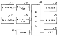
- FIG. 2 is a block diagram of an electronic device according to an embodiment of the present invention.
- FIG. 3 is a flowchart showing an operation according to an embodiment of the present invention.
- FIG. 4 is an explanatory diagram showing an example of display on the electronic device according to an embodiment of the present invention.
- FIG. 5 is an explanatory diagram showing an example of display on the electronic apparatus according to an embodiment of the present invention.
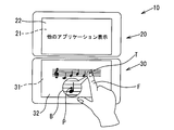
- FIG. 6 is an explanatory diagram showing an example of different displays of the electronic device according to an embodiment of the present invention.
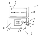
- FIG. 7 is an explanatory diagram showing an example of a further different display of the electronic apparatus according to an embodiment of the present invention.
- FIG. 8 is an explanatory diagram showing an example of display when there is one display screen in the electronic apparatus according to an embodiment of the present invention.
- FIG. 9 is an explanatory diagram showing an example of display on the other display screen in the electronic apparatus according to one embodiment of the present invention.
- FIGS. 10A to 10E are explanatory diagrams showing an example of display transition when an icon is moved across two display screens in the electronic apparatus according to the embodiment of the invention.
- An embodiment of the present invention has at least one display screen (21) (31), at least one of which includes a touch panel (22) (32), and activates and displays one or more applications.
- Information such as characters, figures, images, images, and videos is displayed on the screen (21) (31), and the user can edit the information by operating the touch panel (22) and / or touch panel (32).
- the present invention relates to an electronic device (10) that can be used.
- the present invention when the information displayed on the display screen (21) (31) is operated on the touch panel (22) (32), the displayed information is
- the present invention relates to the electronic device (10) which has solved the problem of being hidden by the fingertip (F) and the like and unable to perform precise operations.
- the electronic device (10) includes display units (20) and (30).
- the display unit (20) (30) includes two display screens (21) (31) capable of displaying information such as characters, figures, images, images, and moving images corresponding to the application desired by the user, and the display Touch panels (22) and (32) operable by a user touching the surface of the screen.
- the display units (20) and (30) are connected to each other by a connecting mechanism (40) so as to be relatively movable by opening and closing or sliding.
- the display units (20) and (30) are not limited to two, and may be one or three or more.
- the first display unit (20) and the second display unit (30) have a display screen (21) capable of displaying information in a housing (23) (33) whose one surface is open. (31) is accommodated so as to be visible from the opening side.
- the display screens (21) and (31) are electrically connected to a control means (60) (see FIG. 2) described later, and can display various information.
- the display unit located on the right back side of the drawing is referred to as a first display unit (20), and the display unit located on the left front side is referred to as a second display unit (30).
- the display screens (21) and (31) are, for example, liquid crystal displays.
- the display units (20) and (30) have touch panels (22) and (32) that can be operated by a user touching with a fingertip (F) or the like on the opening side of the display screens (21) and (31).
- the touch panels (22) and (32) are transparent so that the display screens (21) and (31) are visible, and are provided so as to close the openings of the housings (23) and (33).
- Examples of the touch panel (22) and (32) method include a capacitance method and a resistance film method.
- the touch panel (22) (32) is electrically connected to the control means (60) via the touch panel determination unit (25) (35) as shown in FIG.
- the touch panel determination unit (25) 35)
- the corresponding coordinate information is input to the control means (60) via the touch panel determination unit (25) (35), Used for various operations.
- the first display unit (20) and the second display unit (30) can be relatively moved by the connecting mechanism (40). Although a detailed description of the connection mechanism (40) is omitted, for example, the first display unit (20) is configured to be slidable and / or rotatable with respect to the second display unit (30). be able to.
- FIG. 2 shows a block diagram of an electronic apparatus according to an embodiment of the present invention. As shown in FIG. 2, all control of the electrical equipment is performed by a control means (60) composed of a CPU or the like.
- the first display screen (21) and the second display screen (31) described above are electrically connected to the control means (60). Also, the display means (63) connected to the control means (60) allows the first display screen (21) and the second display screen (31) to display various information corresponding to the application software to be used. Yes.
- the first touch panel (22) and the second touch panel (32) are electrically connected to the control means (60) via the first touch panel determination unit (25) and the second touch panel determination unit (35), respectively. Yes. User input from the first touch panel (22) and the second touch panel (32) is transmitted as coordinate information to the control means (60) via the touch panel determination units (25) and (35).
- the control means (60) edits, operates, etc. the information on the display screens (21), (31) according to the input.
- the display means (63) extracts information on the peripheral area of the coordinates based on the coordinate information acquired by the touch panel determination sections (25) and (35), and displays it in the vicinity of the coordinates.
- the display means (63) enlarges and displays the information of the peripheral area of the coordinates (see FIGS. 5 to 7) in order to improve the visibility (see FIGS. 8 and 10). Reference) or reduced display.
- the electronic device (10) has a plurality of display screens (21) (31)
- the coordinates are displayed on a display screen (for example, (21)) different from the touch panel (for example, (32)) related to the user's operation.
- Information on the peripheral area of the image may be displayed (see FIG. 9).
- control means (60) is electrically connected to a memory (61) for storing various operations of the electronic device (10) and various data desired by the user.
- the control means (60) operates the operating system and can start one application or a plurality of applications simultaneously.
- the application can be displayed continuously on the first display screen (21) and the second display screen (31), or information related to different applications can be displayed.
- On the home screen which is an operating system screen, icons and the like are displayed on the first display screen (21) and / or the second display screen (31).
- Information can be edited by operating the first touch panel (22) and / or the second touch panel (32). More specifically, information on applications such as browsers is displayed on the first display screen (21), information on applications such as drawing software is displayed on the second display screen (31), and the second touch panel (32). It is conceivable to perform drawing editing as shown in FIG.
- step 3 information is displayed on the first display screen (21) and the second display screen (31) by the display means (63) (see step 1 and FIG. 4 in FIG. 3), and the user touches the first touch panel (22) and When the second touch panel (32) is operated (step 2), the touch point (coordinate information) of the operated touch panel (hereinafter referred to as the second touch panel (32)) is displayed as a touch panel determination unit (touch panel determination unit (35)). ) (Step 3).
- the display means (63) extracts information on the peripheral area of the touch point (coordinate information) received by the touch panel determination unit (35) (step 4), and displays the display screen, that is, the second display screen ( The information of the peripheral area of the touch point is enlarged and displayed at a position different from the touch point of 31) (step 5).
- the display of the peripheral area of the touch point can be performed in a balloon (B) drawn from the touch point (T) as shown in FIG.
- a balloon (B) drawn from the touch point (T) as shown in FIG.
- the user can visually recognize that it is an enlarged display of the peripheral area of the touch point (T).
- step 6 When the user performs a desired operation with reference to FIG. 5 and completes the operation (step 6), the enlarged display by the display means (63) ends (step 7).
- the information on the second display screen (31) is hidden by the fingertip (F) or the like and the touch point (T) cannot be visually recognized.
- the information on the second display screen (31) related to the user's touch point (T) is enlarged and displayed in the second display screen (31) together with the pointer (P).
- the balloon (B) information selected by the second touch panel (32) can be confirmed, and a desired precise operation can be performed.
- a circular or rectangular area of about 1 to 2 cm that can be hidden by the user's finger (F) can be exemplified as the peripheral area of the touch point (T) to be enlarged and displayed.
- the enlargement ratio of the information displayed in the balloon (B) is preferably about 1 to 3 times.
- the area where the balloon (B) is displayed is preferably an area at the upper right of the touch point (T) in terms of operability and visibility. However, depending on the part of the display screen touched by the user, the area shown in FIGS. As shown, it is of course possible to set the area for displaying the balloon (B) to the lower left or the left. At this time, as shown in FIG. 6, it is desirable to display the balloon (B) so as not to overlap the graphic displayed by the application.
- application software that is assumed to improve operability as much as possible by this embodiment includes photo retouching software, video editing software, composition sequencer software (see FIG. 6), game software (see FIG. 7), and the like. It can be illustrated.
- the peripheral information of the touch point (T) is enlarged and displayed.
- the present invention can be variously modified.
- FIG. 8 shows an example of one-screen display in which the second display screen (31) is made invisible by sliding and rotating below the first display screen (21).
- a text frame (80) is displayed on the upper side
- a soft keyboard (81) is displayed on the lower side.
- the display means (63) displays the pressed key "k”. It is displayed in a frame (B '). Thereby, the user can confirm the key that he / she pressed by visual recognition, can prevent a typo and the like, and can improve operability.
- FIG. 9 shows an embodiment in which a text frame (80) is displayed on the first display screen (21) and a soft keyboard (81) is displayed on the second display screen (31).
- the display means (63) displays the pressed key "k” on the first display screen (21 ) Is displayed in a frame (B ′).
- the user can confirm the key that he / she pressed by visual recognition, can prevent a typo and the like, and can improve operability.
- the frame (B ′) overlaps the soft keyboard (81) due to the restriction on the size of the display screen, but in the embodiment of FIG. 9, the frame (B ′) appears on the first display screen (21). ) Is displayed, such overlapping can be prevented, and visibility and operability can be further improved.
- FIG. 10 shows transition of the display state in which information (the mail icon (i) in the figure) is moved across a plurality of display screens (21) and (31).
- FIG. 10 (a) for example, when the icon (i) on the first display screen (21) is dragged downward with the finger (F) as shown in FIG. 10 (b) on the home screen, The icon (i) hidden by the finger (F) is displayed in the balloon (B) in the same manner as described above.
- the display means (63) displays the balloon (B) from the first display screen (21) to the second display screen (31) according to the position of the finger (F). To move to. Thereby, since the balloon (B) can be displayed at a position close to the icon (i) touched by the user, visibility and operability can be improved.
- the display means (63) displays the display of the balloon (B) as shown in FIG. ) (31) so as to avoid the boundary portion, the balloon (B) can be easily recognized.
- the second display screen (31) When the balloon (B) moved to the second display screen (31) has a finger (F) on the second touch panel (32), as shown in FIG. 10 (e), the second display screen (31) It may be displayed on.
- the drag operation extending from the first touch panel (22) to the second touch panel (32) is a continuous drag operation.
- the drag operation signal between the touch panels (22) (32) may be interrupted. There is. In such a case, when the first touch panel determination unit (25) receives the drag operation signal and then receives the drag operation signal to the second touch panel determination unit (35) within a predetermined time, it is a continuous drag operation. May be determined.
- This embodiment is useful as an electronic device that can display a touch point that is hidden by the fingertip when operating the touch panel, and can improve operability.
Landscapes
- Engineering & Computer Science (AREA)
- Theoretical Computer Science (AREA)
- General Engineering & Computer Science (AREA)
- Physics & Mathematics (AREA)
- Human Computer Interaction (AREA)
- General Physics & Mathematics (AREA)
- Mathematical Physics (AREA)
- Computer Hardware Design (AREA)
- User Interface Of Digital Computer (AREA)
- Position Input By Displaying (AREA)
Abstract
本発明に係る電子機器は、情報を表示可能な表示画面21,31と、該表示画面に設けられ、ユーザが操作を行なうタッチパネル22,32と、該タッチパネルに電気的に接続され、ユーザの操作によるタッチパネルから座標情報を受信するタッチパネル判定部25,35と、表示画面に情報を表示する表示手段63と、を有する電子機器であって、前記表示手段は、タッチパネル判定部が座標情報を受信すると、該座標を含む周縁領域の情報を前記表示画面における前記座標とは異なる位置に表示する表示手段63を有する。
Description
本発明は、複数の表示画面とその少なくとも1つにタッチパネルを有する電子機器に関するものである。
表示画面にタッチパネル式の操作手段を具えた電子機器が知られている。
この種の電子機器では、ユーザは、表示画面に表示された文字や画像を視認するだけでなく、タッチパネルをタップ、ダブルタップ、フリック、ドラッグ等することで操作や編集等を行なうことができる。
この種の電子機器では、ユーザは、表示画面に表示された文字や画像を視認するだけでなく、タッチパネルをタップ、ダブルタップ、フリック、ドラッグ等することで操作や編集等を行なうことができる。
タッチパネル式の操作手段として、抵抗膜方式のものや静電容量方式のものが主流であるが、特に静電容量方式のタッチパネルを用いる場合、ユーザが指先で操作を行なう必要がある。
表示画面に表示された情報に対して、タッチパネルをユーザが直接指先で触れて操作する場合、指先とタッチパネルとの接点となるタッチポイントが指先で隠れてしまうから、精密なタッチ動作を行なうことが難しい。
特に、タッチパネルにより各種の操作、例えば、描画、音楽や動画編集、ゲーム、等の操作を行なう場合に、タッチポイントを視認できなければ、正確な操作を行なうことができない。
特に、タッチパネルにより各種の操作、例えば、描画、音楽や動画編集、ゲーム、等の操作を行なう場合に、タッチポイントを視認できなければ、正確な操作を行なうことができない。
よって、タッチパネルを操作する際に、指先に隠れるタッチポイントを別の場所に表示することで、操作性を可及的に向上させることのできる電子機器が望まれている。
本発明の一態様に係る電子機器は、
情報を表示可能な表示画面と、
該表示画面に設けられ、ユーザが操作を行なうタッチパネルと、
該タッチパネルに電気的に接続され、ユーザの操作によるタッチパネルから座標情報を受信するタッチパネル判定部と、
表示画面に情報を表示する表示手段と、
を有する電子機器であって、
前記表示手段は、タッチパネル判定部が座標情報を受信すると、該座標を含む周縁領域の情報を前記表示画面における前記座標とは異なる位置に表示する。
情報を表示可能な表示画面と、
該表示画面に設けられ、ユーザが操作を行なうタッチパネルと、
該タッチパネルに電気的に接続され、ユーザの操作によるタッチパネルから座標情報を受信するタッチパネル判定部と、
表示画面に情報を表示する表示手段と、
を有する電子機器であって、
前記表示手段は、タッチパネル判定部が座標情報を受信すると、該座標を含む周縁領域の情報を前記表示画面における前記座標とは異なる位置に表示する。
本発明の一実施例は、少なくとも1つの表示画面(21)(31)を有し、その少なくともその1つにタッチパネル(22)(32)を具え、1又は複数のアプリケーションを起動して、表示画面(21)(31)に文字、図形、画像、映像、動画等の情報を表示し、ユーザがタッチパネル(22)及び/又はタッチパネル(32)を操作することで、情報を編集等することのできる電子機器(10)に関するものである。
より具体的には、本発明の一実施例は、表示画面(21)(31)に表示された情報をタッチパネル(22)(32)で操作する際に、表示されている情報が、ユーザの指先(F)等で隠れてしまい、精密な操作を行なうことができなくなる問題を解消した電子機器(10)に関するものである。
以下、本発明の一実施例に係る電子機器(10)について、携帯型の電子機器を例に挙げて図面を用いて説明するが、以下に示す具体的な電子機器の構造、構成は、説明のためのものであって、本発明を限定的に解釈すべきでないことは勿論である。
まず、本実施例に係る携帯型電子機器(10)の構造について説明を行なう。
電子機器(10)は、図1に示すように、表示部(20)(30)を有する。表示部(20)(30)は、ユーザの所望するアプリケーションに対応して、文字、図形、画像、映像、動画等の情報を表示可能な2つの表示画面(21)(31)と、該表示画面の表面にユーザが触れることで操作可能なタッチパネル(22)(32)とを有する。表示部(20)(30)は、連結機構(40)によって相対的に開閉やスライド等により移動可能に連結される。なお、表示部(20)(30)は、2つに限定されず、1つでもよいし、3つ以上とすることもできる。
電子機器(10)は、図1に示すように、表示部(20)(30)を有する。表示部(20)(30)は、ユーザの所望するアプリケーションに対応して、文字、図形、画像、映像、動画等の情報を表示可能な2つの表示画面(21)(31)と、該表示画面の表面にユーザが触れることで操作可能なタッチパネル(22)(32)とを有する。表示部(20)(30)は、連結機構(40)によって相対的に開閉やスライド等により移動可能に連結される。なお、表示部(20)(30)は、2つに限定されず、1つでもよいし、3つ以上とすることもできる。
第1表示部(20)及び第2表示部(30)は、図1に示すように、一方の面が開口した筺体(23)(33)内に、情報を表示可能な表示画面(21)(31)が開口側から視認可能となるように収容されている。表示画面(21)(31)は、後述する制御手段(60)(図2参照)に電気的に接続され、各種情報を表示可能となっている。なお、図1において、紙面右奥側に位置する表示部を第1表示部(20)、左手前側に位置する表示部を第2表示部(30)と称する。
表示画面(21)(31)は、例えば、液晶ディスプレイである。表示部(20)(30)は、表示画面(21)(31)の開口側に、ユーザが指先(F)等で触れることにより操作可能なタッチパネル(22)(32)を有する。タッチパネル(22)(32)は、表示画面(21)(31)が視認可能となるよう透明であり、筺体(23)(33)の開口を塞ぐように設けられる。タッチパネル(22)(32)の方式として、静電容量方式又は抵抗膜方式を例示できる。
タッチパネル(22)(32)は、図2に示すようにタッチパネル判定部(25)(35)を介して制御手段(60)に電気的に接続される。ユーザがタッチパネル(22)(32)を指先(F)等で触れて操作することにより、該当する座標情報は、タッチパネル判定部(25)(35)を介して制御手段(60)に入力され、各種操作等に用いられる。
第1表示部(20)と第2表示部(30)は、連結機構(40)により、相対的に移動可能とすることができる。連結機構(40)についての詳細な構成の説明は省略するが、例えば、第1表示部(20)を第2表示部(30)に対してスライド可能及び/又は回動可能とする構成とすることができる。
図2は、本発明の一実施例に係る電子機器のブロック図を示している。
電気機器のすべての制御は、図2に示すように、CPU等から構成される制御手段(60)により行なわれる。
電気機器のすべての制御は、図2に示すように、CPU等から構成される制御手段(60)により行なわれる。
制御手段(60)には、前述した第1表示画面(21)、第2表示画面(31)が電気的に接続されている。また、制御手段(60)に接続された表示手段(63)により、第1表示画面(21)及び第2表示画面(31)は、使用するアプリケーションソフトに対応した各種情報を表示可能となっている。
また、第1タッチパネル(22)及び第2タッチパネル(32)は、夫々第1タッチパネル判定部(25)、第2タッチパネル判定部(35)を介して制御手段(60)に電気的に接続されている。第1タッチパネル(22)及び第2タッチパネル(32)からのユーザの入力は、座標情報としてタッチパネル判定部(25)(35)を介して制御手段(60)に送信される。制御手段(60)は、入力に応じて、表示画面(21)(31)の情報を編集、操作等行なう。
さらに、前記表示手段(63)は、上記タッチパネル判定部(25)(35)により取得された座標情報に基づいて、該座標の周縁領域の情報を抽出し、座標の近傍に表示する。
なお、表示手段(63)は、視認性を高めるために、前記座標の周縁領域の情報を拡大して表示しているが(図5乃至図7参照)、等倍表示(図8及び図10参照)や縮小表示でも構わない。さらに、電子機器(10)が複数の表示画面(21)(31)を有する場合には、ユーザの操作に係るタッチパネル(例えば(32))とは異なる表示画面(例えば(21))に前記座標の周縁領域の情報を表示するようにしてもよい(図9参照)。
なお、表示手段(63)は、視認性を高めるために、前記座標の周縁領域の情報を拡大して表示しているが(図5乃至図7参照)、等倍表示(図8及び図10参照)や縮小表示でも構わない。さらに、電子機器(10)が複数の表示画面(21)(31)を有する場合には、ユーザの操作に係るタッチパネル(例えば(32))とは異なる表示画面(例えば(21))に前記座標の周縁領域の情報を表示するようにしてもよい(図9参照)。
制御手段(60)には、上述の他、電子機器(10)の各種動作やユーザの所望する各種データ等を記憶するメモリ(61)等が電気的に接続されている。
制御手段(60)は、オペレーティングシステムを作動させ、1のアプリケーション又は複数のアプリケーションを同時に起動可能となっている。アプリケーションは、第1表示画面(21)と第2表示画面(31)に連続して表示したり、夫々異なるアプリケーションに係る情報を表示することができる。また、オペレーティングシステムの画面であるホーム画面では、アイコン等が第1表示画面(21)及び/又は第2表示画面(31)に表示される。
第1タッチパネル(22)及び/又は第2タッチパネル(32)を操作することで、情報の編集等を行なうことがきる。より具体的には、第1表示画面(21)にブラウザ等のアプリケーションの情報を表示し、第2表示画面(31)に描画ソフト等のアプリケーションの情報を表示して、第2タッチパネル(32)の操作により、図3に示すような描画編集等を行なうことが考えられる。
然して、表示手段(63)により、第1表示画面(21)と第2表示画面(31)に情報を表示し(図3のステップ1及び図4参照)、ユーザが第1タッチパネル(22)及び/又は第2タッチパネル(32)を操作すると(ステップ2)、操作されたタッチパネル(以下では第2タッチパネル(32)とする)のタッチポイント(座標情報)をタッチパネル判定部(タッチパネル判定部(35))に送信する(ステップ3)。このとき、表示手段(63)は、タッチパネル判定部(35)が受信したタッチポイント(座標情報)の周縁領域の情報を抽出して(ステップ4)、当該表示画面、即ち、第2表示画面(31)のタッチポイントとは異なる位置にタッチポイントの周縁領域の情報を拡大して表示するようにしている(ステップ5)。
タッチポイントの周縁領域の表示は、図5に示すように、タッチポイント(T)から引き出された吹き出し(B)内に行なうことができる。吹き出し(B)にタッチポイント(T)を示すポインタ(P)を合わせて表示することで、ユーザは視覚的にタッチポイント(T)の周縁領域の拡大表示であることを認識することができる。
ユーザが図5を参照しながら、所望の操作を行ない、操作を完了すると(ステップ6)、表示手段(63)による拡大表示は終了する(ステップ7)。
なお、ユーザが、指やスタイラス等でタッチパネル(22)(32)をタッチしてから素早く払う操作である所謂フリックやタッチパネル(22)(32)にタッチしたままタッチポイント(T)を移動させる操作である所謂ドラッグ等の操作を行なったときには、その軌跡に合わせて、周縁領域の吹き出し(B)による表示も移動するようにすることが望ましい。
通常、ユーザが指先(F)等で第2タッチパネル(32)を操作すると、第2表示画面(31)の情報が指先(F)等で隠れて、タッチポイント(T)を視認することができない。しかしながら、本実施例では、ユーザのタッチポイント(T)に係る第2表示画面(31)の情報がポインタ(P)と共に第2表示画面(31)内に拡大して表示されるので、ユーザが吹き出し(B)を参照することで、第2タッチパネル(32)により選択等した情報を確認することができ、所望する精密な操作を行なうことができる。
なお、タッチポイント(T)の拡大表示する周縁領域として、ユーザの指(F)で隠れることが考えられる約1~2cm程度の円形又は矩形の領域を例示することができる。また、吹き出し(B)に表示される情報の拡大比率は、1倍以上3倍以下程度が好適である。
吹き出し(B)を表示する領域は、タッチポイント(T)の斜め右上の領域が操作性及び視認性の点で望ましいが、ユーザの触れている表示画面の部位によっては、図6及び図7に示すように、吹き出し(B)の表示を行なう領域を左下や左等にすることも勿論可能である。このとき、図6に示すように、アプリケーションにより表示されている図形等と重ならないように避けて吹き出し(B)を表示することが望ましい。
本実施例により可及的に操作性が向上すると想定されるアプリケーションソフトとして、上記以外にフォトレタッチソフト、動画編集ソフト、作曲用シーケンサーソフト(図6参照)、ゲームソフト(図7参照)等を例示できる。
上記実施例では、タッチポイント(T)の情報の視認性や操作性を高めるために、タッチポイント(T)の周縁の情報を拡大表示するようにしているが、拡大表示とせずに、等倍又は縮小して表示することも勿論可能である。また、以下に示すように、本発明は種々の変形が可能である。
図8及び図9は、メールソフト等の文書を作成するアプリケーションを起動した場合の実施例である。
図8は、第2表示画面(31)を第1表示画面(21)の下方にスライド及び回動させて視認不能とした1画面表示の実施例である。視認可能な第1表示画面(21)には、上側にテキスト枠(80)が表示されており、下側にソフトキーボード(81)が表示されている。
図8は、第2表示画面(31)を第1表示画面(21)の下方にスライド及び回動させて視認不能とした1画面表示の実施例である。視認可能な第1表示画面(21)には、上側にテキスト枠(80)が表示されており、下側にソフトキーボード(81)が表示されている。
図8において、ユーザがソフトキーボード(81)上の何れかのキー(図示では「k」)を指(F)で押したときに、表示手段(63)は、押されたキー「k」を枠囲み(B’)で表示するようにしている。これにより、ユーザは自ら押したキーを視認により確認することができ、タイプミス等を防止でき、操作性を向上させることができる。
図9は、第1表示画面(21)にテキスト枠(80)を表示し、第2表示画面(31)にソフトキーボード(81)を表示した実施例である。ユーザがソフトキーボード(81)上の何れかのキー(図示では「k」)を指(F)で押すと、表示手段(63)は、押されたキー「k」を第1表示画面(21)に枠囲み(B’)で表示するようにしている。これにより、ユーザは自ら押したキーを視認により確認することができ、タイプミス等を防止でき、操作性を向上させることができる。
図8では表示画面の大きさの制約上、ソフトキーボード(81)に枠囲み(B’)が重なっているが、図9の実施例では、第1表示画面(21)に枠囲み(B’)を表示するようにしたことで、このような重なりを防ぐことができ、さらに視認性、操作性を向上することができる。
図10は、複数の表示画面(21)(31)に亘って情報(図示ではメールアイコン(i))を移動させた表示状態の遷移を示している。図10(a)に示すように、ホーム画面上で、例えば、第1表示画面(21)のアイコン(i)を図10(b)に示すように指(F)により下方向にドラッグすると、指(F)で隠れているアイコン(i)は、上記と同様の要領で吹き出し(B)中に表示される。
この状態で、図10(b)乃至図10(d)に示すように、第1表示画面(21)から第2表示画面(31)、即ち、第1タッチパネル(22)から第2タッチパネル(32)へ跨るようにドラッグ操作を行なうと、指(F)の位置に応じて、表示手段(63)は、吹き出し(B)の表示を第1表示画面(21)から第2表示画面(31)へ移動させるようにしている。これにより、ユーザが触れているアイコン(i)に近い位置に吹き出し(B)の表示を行なうことができるから、視認性、操作性を高めることができる。
なお、第1タッチパネル(22)から第2タッチパネル(32)へ吹き出し(B)を移動させる際に、表示手段(63)は、図10に示すように吹き出し(B)の表示を表示画面(21)(31)の境界部分を避けるように移動させることで、吹き出し(B)を視認し易くすることができる。
なお、第1タッチパネル(22)から第2タッチパネル(32)へ吹き出し(B)を移動させる際に、表示手段(63)は、図10に示すように吹き出し(B)の表示を表示画面(21)(31)の境界部分を避けるように移動させることで、吹き出し(B)を視認し易くすることができる。
第2表示画面(31)へ移動した吹き出し(B)は、第2タッチパネル(32)に指(F)がある場合には、図10(e)に示すように、第2表示画面(31)に表示すればよい。
なお、第1タッチパネル(22)と第2タッチパネル(32)との間に間隔があっても、指(90)で操作した場合には、タッチパネル(22)(32)と接触する面積は比較的大きいため、第1タッチパネル(22)から第2タッチパネル(32)へ跨るドラッグ操作は連続するドラッグ操作であると認識することができる。しかしながら、タッチパネル(22)(32)の間隔が広い場合や、スタイラス等でタッチパネル(22)(32)を操作したときに、タッチパネル(22)(32)間でドラッグ操作の信号が途切れてしまうことがある。このような場合、第1タッチパネル判定部(25)がドラッグ操作の信号を受信した後、所定時間内に第2タッチパネル判定部(35)にドラッグ操作の信号を受信すると、連続するドラッグ操作であると判定するようにしてもよい。
本実施例は、タッチパネルを操作する際に指先に隠れるタッチポイントを表示することができ、操作性を高めることのできる電子機器として有用である。
(10) 電子機器
(20) 第1表示部
(21) 第1表示画面
(22) 第1タッチパネル
(25) 第1タッチパネル判定部
(30) 第2表示部
(31) 第2表示画面
(32) 第2タッチパネル
(35) 第2タッチパネル判定部
(40) 連結機構
(60) 制御手段
(63) 表示手段
(B) 吹き出し
(P) ポインタ
(F) 指先
(T) タッチポイント
(20) 第1表示部
(21) 第1表示画面
(22) 第1タッチパネル
(25) 第1タッチパネル判定部
(30) 第2表示部
(31) 第2表示画面
(32) 第2タッチパネル
(35) 第2タッチパネル判定部
(40) 連結機構
(60) 制御手段
(63) 表示手段
(B) 吹き出し
(P) ポインタ
(F) 指先
(T) タッチポイント
Claims (6)
- 情報を表示可能な表示画面と、
該表示画面に設けられ、ユーザが操作を行なうタッチパネルと、
該タッチパネルに電気的に接続され、ユーザの操作によるタッチパネルから座標情報を受信するタッチパネル判定部と、
表示画面に情報を表示する表示手段と、
を有する電子機器であって、
前記表示手段は、タッチパネル判定部が座標情報を受信すると、該座標を含む周縁領域の情報を前記表示画面における前記座標とは異なる位置に表示する、
電子機器。 - 前記表示手段は、前記座標を含む周縁領域の情報を拡大して表示する請求項1に記載の電子機器。
- 前記表示手段は、前記表示画面に表示された他の情報を避けて前記座標を含む周縁領域の情報を表示する請求項1に記載の電子機器。
- 前記表示画面は複数配備され、前記表示手段は、ユーザの操作によるタッチパネルとは異なる表示画面に、前記座標を含む周縁領域の情報を表示する請求項1に記載の電子機器。
- タッチパネルは、静電容量方式である請求項1に記載の電子機器。
- 情報を表示可能な表示画面と、
該表示画面に設けられ、ユーザが操作を行なうタッチパネルと、
該タッチパネルに電気的に接続され、ユーザの操作によるタッチパネルから座標情報を受信するタッチパネル判定部と、
表示画面及びタッチパネル判定部に電気的に接続され、表示画面に情報を表示する表示手段と、
を有し、
表示手段は、表示画面に情報を表示し、タッチパネル判定部が座標情報を受信すると、該座標を含む周縁領域の情報を前記表示画面における該座標とは異なる位置に表示する、
電子機器の制御方法。
Priority Applications (1)
| Application Number | Priority Date | Filing Date | Title |
|---|---|---|---|
| US14/007,237 US20140015785A1 (en) | 2011-03-25 | 2012-03-26 | Electronic device |
Applications Claiming Priority (2)
| Application Number | Priority Date | Filing Date | Title |
|---|---|---|---|
| JP2011067520A JP2012203644A (ja) | 2011-03-25 | 2011-03-25 | 電子機器 |
| JP2011-067520 | 2011-03-25 |
Publications (1)
| Publication Number | Publication Date |
|---|---|
| WO2012133272A1 true WO2012133272A1 (ja) | 2012-10-04 |
Family
ID=46930990
Family Applications (1)
| Application Number | Title | Priority Date | Filing Date |
|---|---|---|---|
| PCT/JP2012/057698 Ceased WO2012133272A1 (ja) | 2011-03-25 | 2012-03-26 | 電子機器 |
Country Status (3)
| Country | Link |
|---|---|
| US (1) | US20140015785A1 (ja) |
| JP (1) | JP2012203644A (ja) |
| WO (1) | WO2012133272A1 (ja) |
Cited By (2)
| Publication number | Priority date | Publication date | Assignee | Title |
|---|---|---|---|---|
| JP2015141612A (ja) * | 2014-01-29 | 2015-08-03 | カシオ計算機株式会社 | 情報処理装置、情報処理方法及びプログラム |
| JPWO2020116001A1 (ja) * | 2018-12-03 | 2021-10-14 | ソニーグループ株式会社 | 情報処理装置および情報処理方法 |
Families Citing this family (12)
| Publication number | Priority date | Publication date | Assignee | Title |
|---|---|---|---|---|
| DE202012100620U1 (de) | 2011-11-22 | 2012-06-13 | Square, Inc. | System zur Bearbeitung von kartenlosen Bezahlungstransaktionen |
| USD732059S1 (en) * | 2012-08-17 | 2015-06-16 | Square, Inc. | Device display screen with a graphical user interface |
| US20140052613A1 (en) | 2012-08-17 | 2014-02-20 | Square, Inc., A Delaware Corporation | Systems and methods for providing gratuities to merchants |
| US11003351B2 (en) * | 2012-12-26 | 2021-05-11 | Gree, Inc. | Display processing method and information device |
| WO2014142468A1 (en) | 2013-03-13 | 2014-09-18 | Samsung Electronics Co., Ltd. | Method of providing copy image and ultrasound apparatus therefor |
| US11096668B2 (en) | 2013-03-13 | 2021-08-24 | Samsung Electronics Co., Ltd. | Method and ultrasound apparatus for displaying an object |
| US11803841B1 (en) | 2013-10-29 | 2023-10-31 | Block, Inc. | Discovery and communication using direct radio signal communication |
| KR20150126193A (ko) * | 2014-05-02 | 2015-11-11 | 삼성전자주식회사 | 복수의 디스플레이를 이용한 컨텐츠 출력 방법 및 그 장치 |
| US10026083B1 (en) | 2014-05-11 | 2018-07-17 | Square, Inc. | Tab for a venue |
| WO2018195730A1 (zh) | 2017-04-24 | 2018-11-01 | 北京小米移动软件有限公司 | 屏幕控制方法及装置 |
| KR102539579B1 (ko) * | 2018-12-18 | 2023-06-05 | 삼성전자주식회사 | 정보의 표시 영역을 적응적으로 변경하기 위한 전자 장치 및 그의 동작 방법 |
| USD964418S1 (en) * | 2020-03-31 | 2022-09-20 | Tata Consultancy Services Limited | Wearable device display screen with graphical user interface |
Citations (3)
| Publication number | Priority date | Publication date | Assignee | Title |
|---|---|---|---|---|
| JP2010152827A (ja) * | 2008-12-26 | 2010-07-08 | Brother Ind Ltd | 入力装置 |
| JP2010181940A (ja) * | 2009-02-03 | 2010-08-19 | Zenrin Datacom Co Ltd | 画像処理装置および画像処理方法 |
| JP2011003012A (ja) * | 2009-06-18 | 2011-01-06 | Toppan Printing Co Ltd | 携帯端末装置、携帯端末表示方法、携帯端末表示システムおよびプログラム |
Family Cites Families (10)
| Publication number | Priority date | Publication date | Assignee | Title |
|---|---|---|---|---|
| WO1994029788A1 (en) * | 1993-06-15 | 1994-12-22 | Honeywell Inc. | A method for utilizing a low resolution touch screen system in a high resolution graphics environment |
| JPH08314620A (ja) * | 1995-05-15 | 1996-11-29 | Omron Corp | 表示装置 |
| JPH1185116A (ja) * | 1997-09-12 | 1999-03-30 | Toshiba Corp | 携帯型情報機器 |
| AU5087800A (en) * | 1999-06-02 | 2000-12-28 | Ncr International, Inc. | Self-service terminal |
| JP4518955B2 (ja) * | 2002-11-29 | 2010-08-04 | コーニンクレッカ フィリップス エレクトロニクス エヌ ヴィ | 接触エリアの移動させられた表現を用いたユーザインタフェース |
| JP4799013B2 (ja) * | 2005-03-11 | 2011-10-19 | 富士通株式会社 | マルチディスプレイにおけるウインドウの表示制御装置 |
| JP5289889B2 (ja) * | 2008-10-24 | 2013-09-11 | シャープ株式会社 | 表示装置、表示装置の制御方法、表示装置を制御するためのプログラム |
| JP4904375B2 (ja) * | 2009-03-31 | 2012-03-28 | 京セラ株式会社 | ユーザインタフェース装置及び携帯端末装置 |
| KR20110092802A (ko) * | 2010-02-10 | 2011-08-18 | 삼성전자주식회사 | 복수개의 표시부를 가지는 단말기의 데이터 운용 방법 및 이를 지원하는 단말기 |
| CN103477304A (zh) * | 2011-02-10 | 2013-12-25 | 三星电子株式会社 | 包含触摸屏显示器的便携式设备以及控制它的方法 |
-
2011
- 2011-03-25 JP JP2011067520A patent/JP2012203644A/ja active Pending
-
2012
- 2012-03-26 US US14/007,237 patent/US20140015785A1/en not_active Abandoned
- 2012-03-26 WO PCT/JP2012/057698 patent/WO2012133272A1/ja not_active Ceased
Patent Citations (3)
| Publication number | Priority date | Publication date | Assignee | Title |
|---|---|---|---|---|
| JP2010152827A (ja) * | 2008-12-26 | 2010-07-08 | Brother Ind Ltd | 入力装置 |
| JP2010181940A (ja) * | 2009-02-03 | 2010-08-19 | Zenrin Datacom Co Ltd | 画像処理装置および画像処理方法 |
| JP2011003012A (ja) * | 2009-06-18 | 2011-01-06 | Toppan Printing Co Ltd | 携帯端末装置、携帯端末表示方法、携帯端末表示システムおよびプログラム |
Cited By (3)
| Publication number | Priority date | Publication date | Assignee | Title |
|---|---|---|---|---|
| JP2015141612A (ja) * | 2014-01-29 | 2015-08-03 | カシオ計算機株式会社 | 情報処理装置、情報処理方法及びプログラム |
| JPWO2020116001A1 (ja) * | 2018-12-03 | 2021-10-14 | ソニーグループ株式会社 | 情報処理装置および情報処理方法 |
| JP7468360B2 (ja) | 2018-12-03 | 2024-04-16 | ソニーグループ株式会社 | 情報処理装置および情報処理方法 |
Also Published As
| Publication number | Publication date |
|---|---|
| JP2012203644A (ja) | 2012-10-22 |
| US20140015785A1 (en) | 2014-01-16 |
Similar Documents
| Publication | Publication Date | Title |
|---|---|---|
| WO2012133272A1 (ja) | 電子機器 | |
| CN103150095B (zh) | 终端和终端操控方法 | |
| CN104756060B (zh) | 基于手势的光标控制 | |
| US8413075B2 (en) | Gesture movies | |
| CN101315593B (zh) | 触控式移动运算装置与应用于其上的触控方法 | |
| US20190258395A1 (en) | Processing capacitive touch gestures implemented on an electronic device | |
| CN1307518C (zh) | 信息显示/输入设备、信息显示/输入方法和信息处理设备 | |
| JP5580694B2 (ja) | 情報処理装置、その制御方法、プログラム及び記憶媒体 | |
| CN105122176B (zh) | 用于管理在电子设备上显示的内容的系统和方法 | |
| CN103270485B (zh) | 触摸输入处理装置、信息处理装置及触摸输入控制方法 | |
| US20150067582A1 (en) | Content navigation structure and transition mechanism | |
| CN103201716B (zh) | 触敏电子设备 | |
| JP2008276776A (ja) | タッチ式タグ・ナビゲーション方法及び関連装置 | |
| CN101876877A (zh) | 触控屏幕缩放显示系统及方法 | |
| US20160063674A1 (en) | Graph display apparatus, graph display method and storage medium | |
| TW200910149A (en) | Electronic device display adjustment interface | |
| EP3278203B1 (en) | Enhancement to text selection controls | |
| JP2017211925A (ja) | 情報処理装置及び画像表示方法 | |
| JP2013016123A (ja) | 表示機器、及び、画面遷移方法 | |
| JP2012155434A (ja) | 電子機器 | |
| US20150015501A1 (en) | Information display apparatus | |
| JP6945345B2 (ja) | 表示装置、表示方法及びプログラム | |
| US20150012858A1 (en) | Mobile information terminal | |
| JP5681013B2 (ja) | 電子機器及びその制御方法 | |
| JP2018133108A (ja) | 電子端末、及びその制御方法とプログラム |
Legal Events
| Date | Code | Title | Description |
|---|---|---|---|
| 121 | Ep: the epo has been informed by wipo that ep was designated in this application |
Ref document number: 12765770 Country of ref document: EP Kind code of ref document: A1 |
|
| WWE | Wipo information: entry into national phase |
Ref document number: 14007237 Country of ref document: US |
|
| NENP | Non-entry into the national phase |
Ref country code: DE |
|
| 122 | Ep: pct application non-entry in european phase |
Ref document number: 12765770 Country of ref document: EP Kind code of ref document: A1 |