WO2012133135A1 - 太陽熱発電設備、この設備に含まれるヘリオスタットの制御方法、この方法を実行する制御装置 - Google Patents
太陽熱発電設備、この設備に含まれるヘリオスタットの制御方法、この方法を実行する制御装置 Download PDFInfo
- Publication number
- WO2012133135A1 WO2012133135A1 PCT/JP2012/057425 JP2012057425W WO2012133135A1 WO 2012133135 A1 WO2012133135 A1 WO 2012133135A1 JP 2012057425 W JP2012057425 W JP 2012057425W WO 2012133135 A1 WO2012133135 A1 WO 2012133135A1
- Authority
- WO
- WIPO (PCT)
- Prior art keywords
- heliostat
- temperature
- correction coefficient
- group
- heliostats
- Prior art date
- Legal status (The legal status is an assumption and is not a legal conclusion. Google has not performed a legal analysis and makes no representation as to the accuracy of the status listed.)
- Ceased
Links
Images












Classifications
-
- F—MECHANICAL ENGINEERING; LIGHTING; HEATING; WEAPONS; BLASTING
- F03—MACHINES OR ENGINES FOR LIQUIDS; WIND, SPRING, OR WEIGHT MOTORS; PRODUCING MECHANICAL POWER OR A REACTIVE PROPULSIVE THRUST, NOT OTHERWISE PROVIDED FOR
- F03G—SPRING, WEIGHT, INERTIA OR LIKE MOTORS; MECHANICAL-POWER PRODUCING DEVICES OR MECHANISMS, NOT OTHERWISE PROVIDED FOR OR USING ENERGY SOURCES NOT OTHERWISE PROVIDED FOR
- F03G6/00—Devices for producing mechanical power from solar energy
- F03G6/06—Devices for producing mechanical power from solar energy with solar energy concentrating means
- F03G6/064—Devices for producing mechanical power from solar energy with solar energy concentrating means having a gas turbine cycle, i.e. compressor and gas turbine combination
-
- F—MECHANICAL ENGINEERING; LIGHTING; HEATING; WEAPONS; BLASTING
- F24—HEATING; RANGES; VENTILATING
- F24S—SOLAR HEAT COLLECTORS; SOLAR HEAT SYSTEMS
- F24S10/00—Solar heat collectors using working fluids
- F24S10/70—Solar heat collectors using working fluids the working fluids being conveyed through tubular absorbing conduits
- F24S10/74—Solar heat collectors using working fluids the working fluids being conveyed through tubular absorbing conduits the tubular conduits are not fixed to heat absorbing plates and are not touching each other
- F24S10/742—Solar heat collectors using working fluids the working fluids being conveyed through tubular absorbing conduits the tubular conduits are not fixed to heat absorbing plates and are not touching each other the conduits being parallel to each other
-
- F—MECHANICAL ENGINEERING; LIGHTING; HEATING; WEAPONS; BLASTING
- F24—HEATING; RANGES; VENTILATING
- F24S—SOLAR HEAT COLLECTORS; SOLAR HEAT SYSTEMS
- F24S20/00—Solar heat collectors specially adapted for particular uses or environments
- F24S20/20—Solar heat collectors for receiving concentrated solar energy, e.g. receivers for solar power plants
-
- F—MECHANICAL ENGINEERING; LIGHTING; HEATING; WEAPONS; BLASTING
- F24—HEATING; RANGES; VENTILATING
- F24S—SOLAR HEAT COLLECTORS; SOLAR HEAT SYSTEMS
- F24S23/00—Arrangements for concentrating solar-rays for solar heat collectors
- F24S23/70—Arrangements for concentrating solar-rays for solar heat collectors with reflectors
-
- F—MECHANICAL ENGINEERING; LIGHTING; HEATING; WEAPONS; BLASTING
- F24—HEATING; RANGES; VENTILATING
- F24S—SOLAR HEAT COLLECTORS; SOLAR HEAT SYSTEMS
- F24S50/00—Arrangements for controlling solar heat collectors
- F24S50/20—Arrangements for controlling solar heat collectors for tracking
- F24S2050/25—Calibration means; Methods for initial positioning of solar concentrators or solar receivers
-
- Y—GENERAL TAGGING OF NEW TECHNOLOGICAL DEVELOPMENTS; GENERAL TAGGING OF CROSS-SECTIONAL TECHNOLOGIES SPANNING OVER SEVERAL SECTIONS OF THE IPC; TECHNICAL SUBJECTS COVERED BY FORMER USPC CROSS-REFERENCE ART COLLECTIONS [XRACs] AND DIGESTS
- Y02—TECHNOLOGIES OR APPLICATIONS FOR MITIGATION OR ADAPTATION AGAINST CLIMATE CHANGE
- Y02E—REDUCTION OF GREENHOUSE GAS [GHG] EMISSIONS, RELATED TO ENERGY GENERATION, TRANSMISSION OR DISTRIBUTION
- Y02E10/00—Energy generation through renewable energy sources
- Y02E10/40—Solar thermal energy, e.g. solar towers
- Y02E10/44—Heat exchange systems
-
- Y—GENERAL TAGGING OF NEW TECHNOLOGICAL DEVELOPMENTS; GENERAL TAGGING OF CROSS-SECTIONAL TECHNOLOGIES SPANNING OVER SEVERAL SECTIONS OF THE IPC; TECHNICAL SUBJECTS COVERED BY FORMER USPC CROSS-REFERENCE ART COLLECTIONS [XRACs] AND DIGESTS
- Y02—TECHNOLOGIES OR APPLICATIONS FOR MITIGATION OR ADAPTATION AGAINST CLIMATE CHANGE
- Y02E—REDUCTION OF GREENHOUSE GAS [GHG] EMISSIONS, RELATED TO ENERGY GENERATION, TRANSMISSION OR DISTRIBUTION
- Y02E10/00—Energy generation through renewable energy sources
- Y02E10/40—Solar thermal energy, e.g. solar towers
- Y02E10/46—Conversion of thermal power into mechanical power, e.g. Rankine, Stirling or solar thermal engines
Definitions
- the present invention includes a heat receiver in which sunlight is irradiated to heat an internal fluid, a turbine driven by the fluid heated by the heat receiver, sunlight reflected by a reflector, and sunlight received by the heat receiver.
- the present invention relates to a solar thermal power generation facility including a plurality of heliostats to be irradiated, a heliostat control method, and a control device that executes the method.
- This solar thermal power generation facility includes a heat receiver that is irradiated with sunlight to heat an internal fluid, a turbine that is driven by the fluid heated by the heat receiver, and a solar reflector that reflects sunlight to the heat receiver.
- a plurality of heliostats that emit light.
- heat amount adjustment means which adjusts the calorie
- an object of the present invention is to provide a technique capable of making the temperature distribution in the heat receiver uniform and improving the durability of the heat receiver.
- the heliostat control device comprises: A heat receiver that has a plurality of heat receiving tubes, the solar tube is irradiated with sunlight, and fluid in the heat receiving tubes is heated; a turbine that is driven by the fluid heated by the heat receiver; and a reflector And a plurality of heliostats that reflect sunlight with the reflecting mirror and can irradiate the heat receiver with sunlight.
- the plurality of heat receiving tubes are divided into a plurality of regions, and each of the plurality of regions includes the plurality of heliostats that can irradiate the heat receiving tubes in the regions with sunlight.
- One heliostat group corresponds.
- the heliostat control device is A load acquisition unit that acquires a load of the turbine, and a heliostat that is operated among the plurality of heliostats that constitute the heliostat group corresponding to the load of the turbine for each of the plurality of heliostat groups.
- a driving heliostat setting unit for determining a driving heliostat, and instructing the driving heliostat for each of the plurality of heliostat groups determined by the driving heliostat setting unit;
- An operation instructing unit that irradiates sunlight to the heat receiving pipe in the region corresponding to the heliostat group including a heliostat.
- a plurality of heat receiving tubes are divided into a plurality of regions, and the heliostat to be operated is determined according to the load in the heliostat group corresponding to the region for each region. Therefore, the irradiation amount of sunlight for each of the plurality of regions of the heat receiver can be controlled, and the irradiation amount of sunlight for each of the plurality of regions can be made uniform. Therefore, according to the heliostat control device, the temperature distribution in the heat receiver is made uniform, and it is possible to avoid that only a part of the heat receiver becomes unnecessarily high and improve the durability of the heat receiver. Can do.
- the operating heliostat setting unit is configured to correspond to the load of the turbine for each of the plurality of heliostat groups.
- a driving heliostat determining unit that preferentially uses a stat and uses the driving heliostat as the amount corresponding to the operating number determined by the operating number setting unit;
- a heliostat having a high driving priority is preferentially used as a driving heliostat corresponding to the number of operating cars. Therefore, the irradiation amount of sunlight for each of the plurality of regions of the heat receiver can be controlled more effectively.
- the operation priority is the heat receiving power among the plurality of heliostats constituting the heliostat group.
- a heliostat having a relatively small amount of heat input to the fluid in the vessel is determined to be high.
- a heliostat having a small heat input is stably operated, and a heliostat having a large heat input is likely to be a target of operation / operation exclusion. Therefore, the control sensitivity of the irradiation amount of sunlight for each of the plurality of regions of the heat receiver can be increased.
- the heliostat control device for each of a plurality of heliostats constituting the heliostat group, the heliostat in the heat receiver by the heliostat.
- a value obtained by dividing the amount of heat input to the fluid by the amount of heat input to the fluid in the heat receiver by all the heliostats constituting the heliostat group is predetermined as the equivalent number of the heliostats.
- the driving heliostat determining unit sets a value obtained by summing up the equivalent number of heliostats for the number of operating units in descending order of the driving priority as an equivalent number of operating units, and the priority level is increased by the equivalent number of operating units.
- Heliostat is preferentially used as the driving heliostat.
- the concept of the equivalent number of heliostats according to the amount of heat input of each heliostat and the equivalent number of equivalent operation is introduced, and the amount of heat input of each heliostat is considered,
- the equivalent number of operating units, which is the final operating number, is defined. Therefore, the heat input amount to the heat receiving pipe in the region corresponding to the heliostat group can be set to the target heat input amount.
- the operating number calculation unit includes a plurality of heliostat groups. The number of heliostats is multiplied by the load of the turbine and the correction coefficient obtained by a predetermined procedure to determine the number of operating heliostats.
- the heliostat control device is a correction coefficient storage in which a first correction coefficient is stored for each of the plurality of heliostat groups. A part.
- the operating number calculation unit obtains the number of operating units of the heliostat group in the first correction coefficient of the heliostat group stored in the correction coefficient storage unit corresponding to the current time.
- One correction factor is used as at least part of the correction factor.
- the heliostat control device since the first correction coefficient is determined at each time for each heliostat group, it is possible to determine an appropriate operating number at each time for each heliostat group.
- the solar thermal power generation facility includes the fluid inlet temperature and outlet temperature for each of the plurality of regions of the heat receiver.
- the heliostat control device when the difference between the outlet temperature and the inlet temperature in the region corresponding to the heliostat group is large, the number of operating heliostat groups corresponding to this region decreases, and the amount of heat input to this region is reduced. be able to. For this reason, in the said heliostat control apparatus, the difference of the exit temperature and entrance temperature of this area
- the solar thermal power generation facility includes: an inlet temperature of the fluid for each of the plurality of regions of the heat receiver; The temperature detection part which detects the high temperature part temperature which is the temperature of the part assumed to become the highest temperature for every said area
- a value obtained by dividing the difference between the inlet temperature and the high temperature temperature in the region is used as a first correction coefficient, and the first correction coefficient is used as at least a part of the correction coefficient.
- the heliostat control device when the difference between the high temperature temperature and the inlet temperature in the region corresponding to the heliostat group is large, the number of operating heliostat groups corresponding to this region decreases, and the amount of heat input to this region decreases. can do. For this reason, in the said heliostat control apparatus, the difference of the high temperature part temperature of this area
- the operating heliostat setting unit has the first correction coefficient determined in advance.
- a coefficient determination unit that determines whether or not the upper limit value is greater than or equal to the upper limit value, and when the coefficient determination unit determines that the first correction coefficient is greater than or equal to the upper limit value, the first correction coefficient is determined in advance.
- a coefficient changing unit that changes the value to less than the upper limit value. Then, after determining the first correction coefficient, when the first correction coefficient is changed by the coefficient changing unit, the operating number calculation unit determines the changed first correction coefficient as a part of the correction coefficient.
- the first correction coefficient obtained by calculation becomes extremely large, and the number of operating heliostats increases. Therefore, it can be avoided that the temperature of the region corresponding to the heliostat group becomes higher than necessary.
- the solar thermal power generation facility is provided for each of the plurality of regions related to the heat receiving pipe.
- a temperature detection unit that detects a high temperature part temperature that is a temperature of a part that is assumed to be the highest temperature in the area and a low temperature part temperature that is a temperature of a part that is assumed to be the lowest temperature in the area.
- the heliostat control device when the difference between the high-temperature part temperature and the low-temperature part temperature in the region corresponding to the heliostat group is large, the number of operating heliostat groups corresponding to this region decreases, and the heat input to this region is reduced. Can be reduced. For this reason, in the said heliostat control apparatus, the difference of the high temperature part temperature of this area
- the solar thermal power generation facility A heliostat control device according to any one of the first to tenth aspects of the present invention, the heat receiver, the turbine, and the plurality of heliostats.
- the solar thermal power generation facility includes a heliostat control device according to any one of the first to tenth aspects of the present invention. Therefore, the temperature distribution in the heat receiver is made uniform, it is possible to avoid that only a part of the heat receiver becomes unnecessarily high, and the durability of the heat receiver can be improved.
- At least some of the plurality of heliostats are arranged in the circumferential direction around the heat receiver.
- at least some of the heliostat groups among the plurality of heliostat groups have different circumferential positions around the heat receiver.
- At least some of the plurality of heliostats are the heat receivers. Is arranged in the perspective direction. Furthermore, at least some of the heliostat groups among the plurality of heliostat groups have different positions in the perspective direction with respect to the heat receiver.
- the heliostats adjacent to each other among the plurality of heliostat groups are adjacent to each other among the plurality of heliostat groups.
- the stat group shares a part of the plurality of heliostats constituting each.
- a heliostat control method includes: A heat receiver that has a plurality of heat receiving tubes, the solar tube is irradiated with sunlight, and fluid in the heat receiving tubes is heated; a turbine that is driven by the fluid heated by the heat receiver; and a reflector And a plurality of heliostats that reflect the sunlight with the reflecting mirror and irradiate the heat receiver with the sunlight, and a heliostat control method for solar thermal power generation equipment.
- the plurality of heat receiving tubes are divided into a plurality of regions, and each of the plurality of regions includes the plurality of heliostats that can irradiate the heat receiving tubes in the regions with sunlight.
- the heliostat control method is A load acquisition step of acquiring the load of the turbine, and a heliostat that is operated among the plurality of heliostats constituting the heliostat group corresponding to the load of the turbine for each of the plurality of heliostat groups.
- a plurality of heat receiving tubes are divided into a plurality of regions, and the heliostat to be operated is determined according to the load in the heliostat group corresponding to the region for each region. Therefore, the irradiation amount of sunlight for each of the plurality of regions of the heat receiver can be controlled, and the irradiation amount of sunlight for each of the plurality of regions can be made uniform. Therefore, according to the heliostat control method, the temperature distribution in the heat receiver is made uniform, it is possible to avoid that only a part of the heat receiver becomes unnecessarily high, and the durability of the heat receiver is improved. Can do.
- the temperature distribution in the heat receiver is made uniform, it is possible to avoid that only a part of the heat receiver becomes unnecessarily high, and the durability of the heat receiver can be improved.
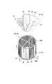
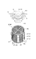
- FIG. 5 is a cross-sectional view taken along line VV in FIG. 4. It is a perspective view of the heat receiving pipe assembly which concerns on 1st embodiment of this invention.
- FIG. It is explanatory drawing which shows the relationship between the area
- FIG. It is explanatory drawing which shows the relationship between the heliostat group which concerns on the other modification of 1st embodiment of this invention, and the area
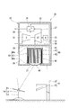
- the solar thermal power generation facility irradiates the heat receiver 40 with sunlight by reflecting the sunlight with the tower facility 20 having the heat receiver 40 irradiated with sunlight and the reflecting mirror 11.
- the heliostat 10 includes a reflecting mirror 11 that reflects sunlight, a support leg 12 that supports the reflecting mirror 11, and a drive controller 13 that directs the reflecting mirror 11 in a target direction.
- a plurality of heliostats 10 are scattered in a ring-shaped region around the tower facility 20.
- a plurality of heliostats 10 are arranged 360 ° in the circumferential direction around the tower facility 20, and a plurality of heliostats 10 are also arranged in the perspective direction with the tower facility 20 as a reference.
- the tower facility 20 includes the above-described heat receiver 40, a compressor 31 that supplies air to the heat receiver 40, and a gas turbine 32 that is driven by air (fluid) heated by the heat receiver 40.
- the generator 33 that generates power by driving the gas turbine 32, the regenerative heat exchanger 34 that exchanges heat between the air compressed by the compressor 31 and the air exhausted from the gas turbine 32, and these are housed.
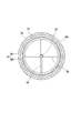
- the tower 21 includes four support columns 22 extending in the vertical direction and a plurality of beams 23 connecting the four support columns 22 to each other. As shown in FIG. 2, the heliostat 10 is not disposed on the diagonal line of the four support columns 22. This is to avoid the column 22 of the tower 21 being present on the optical path of sunlight reflected by the reflecting mirror 11 of the heliostat 10 and directed to the heat receiver 40. Further, the plurality of beams 23 of the tower 21 are also arranged so as not to be present on the optical path of sunlight reflected by the reflecting mirror 11 of the heliostat 10 and toward the heat receiver 40.
- a lower storage chamber 26 and an upper storage chamber 28 are formed inside the storage 25.
- a circular opening 27 for taking sunlight into the lower storage chamber 26 is formed in the lower portion of the lower storage chamber 26.
- a heat receiver 40 is stored in the lower storage chamber 26.
- the upper storage chamber 28 stores a compressor 31, a gas turbine 32, a generator 33, and a regenerative heat exchanger 34.
- the compressor 31 and the heat receiver 40 are connected via a regenerative heat exchanger 34 by a compressed air supply pipe 35 that guides the air compressed by the compressor 31 to the heat receiver 40.
- the heat receiver 40 and the gas turbine 32 are connected by a heated air supply pipe 36 that sends the air heated by the heat receiver 40 to the gas turbine 32.
- the gas turbine 32 and the regenerative heat exchanger 34 are connected by an exhaust pipe 37 that sends exhaust gas from the gas turbine 32 to the regenerative heat exchanger 34.
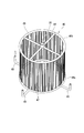
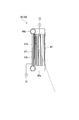
- the heat receiver 40 includes a cylindrical casing 41 and a heat receiving pipe assembly 45 accommodated in the casing 41.
- the casing 41 has a side peripheral wall plate 42 and a top plate 43.
- a circular opening 44 is formed on the lower side of the casing 41. Both the opening 44 of the casing 41 and the opening 27 of the storage 25 described above are formed slightly larger than the spot diameter of sunlight.
- a heat insulating material is provided on the inner surface of the casing 41 in order to suppress radiation to the outside of the thermal energy.
- the casing 41 is suspended from the partition wall 29 by a hook 39 fixed to the partition wall 29 that partitions the lower storage chamber 26 and the upper storage chamber 28 of the storage 25.
- the lower end of the hook 39 passes through the top plate 43 of the casing 41 and is attached to the heat receiving pipe assembly 45. That is, not only the casing 41 of the heat receiver 40 but also the heat receiving pipe assembly 45 is suspended from the partition wall 29 by the hook 39.
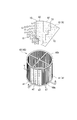
- the heat receiving pipe assembly 45 includes a plurality of receiving pipes that connect a lower header pipe 46a that is formed in a ring shape, an upper header pipe 46b that is also formed in a ring shape, and a lower header pipe 46a and an upper header pipe 46b that extend vertically. It has a heat pipe 47, an inlet pipe 48 for sending air from the compressor 31 to the lower header pipe 46a, and an outlet pipe 49 for sending air from the upper header pipe 46b to the gas turbine 32.
- the plurality of heat receiving pipes 47 are arranged at predetermined intervals in the circumferential direction of the ring-shaped lower header pipe 46a and the upper header pipe 46b.
- the sunlight from the heliostat 10 is basically applied to the heat receiving tube 47.
- the heat receiving pipe 47 rises to a high temperature. Since the heat receiving pipe 47 rises to a high temperature in this way, the heat receiving pipe 47 extends in the vertical direction as described above so that bending stress due to its own weight does not act on the heat receiving pipe 47.
- the lower header pipe 46 a is located on the outer peripheral side of the casing 41 and is not stored in the casing 41.
- a plurality of inlet pipes 48 are connected to the outer peripheral side of the lower header pipe 46a.
- the plurality of inlet pipes 48 are connected to a compressed air supply pipe 35 extending from the compressor 31.
- a plurality of outlet pipes 49 are connected to the inner peripheral side of the upper header pipe 46b so as to connect the opposing portions of the ring-shaped upper header pipe 46b.
- a heated air supply pipe 36 for sending air from the heat receiving pipe assembly 45 to the gas turbine 32 is connected to a portion where the plurality of outlet pipes 49 intersect each other.
- the plurality of heat receiving tubes 47 arranged in the circumferential direction are divided into a plurality of regions a1, a2,..., Ai,. Each of the areas a1, a2,..., Ai,.
- the region in which the plurality of heliostats 10 are arranged is divided into a plurality of partial regions in the circumferential direction around the tower facility 20, for example, as shown in FIG. 7B.
- a plurality of heliostats 10 are arranged in each partial region.
- a plurality of heliostats 10 in the partial region constitute one heliostat group A.
- a heliostat group identifier is set for each of the heliostat groups A1, A2,..., Ai,.
- the number of heliostat groups A is the same as the number of regions a related to the heat receiving pipe 47.
- a heliostat number (identifier) is set for each of the plurality of heliostats 10 constituting the heliostat group A.
- the heliostat group A includes a plurality of heliostats 10 constituting the heliostat group A among the plurality of regions a related to the heat receiving tube 47, and the region a that can irradiate the plurality of heat receiving tubes 47 in the region with sunlight. , Are associated.
- the plurality of heliostats 10 constituting the heliostat group A1 located on the opposite side with respect to the center of the heat receiver 40 emits sunlight. Can be irradiated. For this reason, this heliostat group A1 which can irradiate sunlight with respect to this area
- the plurality of heliostats 10 constituting the heliostat group A are all different from the plurality of heliostats 10 constituting the adjacent heliostat group A.
- a part of the plurality of heliostats 10 constituting the heliostat group A constitutes a part of the plurality of heliostats 10 constituting the adjacent heliostat group A as shown in FIGS. 8A and 8B.
- adjacent heliostat groups A1 and A2 may share a part of the plurality of heliostats 10 constituting each.
- the heliostat 10a belonging to both of the two heliostat groups A1 and A2 irradiates the two regions a1 and a2 related to the heat receiving tube 47 with sunlight.
- the region a related to the heat receiving tube 47 is divided in the circumferential direction.
- the region a may be divided in the vertical direction, that is, in the air flow direction in the heat receiving pipe 47.
- the corresponding plurality of heliostat groups A are arranged in the perspective direction with respect to the tower facility 20.
- the heliostat group A11 on the farthest side from the tower facility 20 corresponds to the lowermost region a11.
- a part of the plurality of heliostats 10 constituting the heliostat group A is a part of the plurality of heliostats 10 constituting the adjacent heliostat group A. May be configured.
- the heliostat control device 50 includes a load acquisition unit 51 that acquires a load control signal indicating the load of the gas turbine 32, and a heliostat 10 that operates among the plurality of heliostats 10 (hereinafter referred to as operation).
- a driving heliostat setting unit 52 that determines a heliostat
- a driving instruction unit 57 that gives a driving instruction to the driving heliostat
- a storage unit 60 that stores various data.
- the operation heliostat setting unit 52 includes an operation number calculation unit 53 for obtaining an operation number of the heliostat 10 corresponding to the load of the gas turbine 32 for each of the plurality of heliostat groups A, and a plurality of heliostats constituting the heliostat group A. 10, a driving heliostat determining unit 54 that uses as many driving heliostats 10 as the number of operating units determined by the operating unit calculation unit 53 is provided.
- the storage unit 60 includes a first correction coefficient 61 used when the operating number calculation unit 53 obtains the operating number of the heliostat 10, a group constituent number 62 that is the total number of heliostats 10 constituting the heliostat group A, and A driving heliostat determining map 63 used when the driving heliostat determining unit 54 determines the driving heliostat is stored.
- all of the first correction coefficient 61, the group configuration number 62, and the driving heliostat determination map 63 are stored for each heliostat group A.
- the driving heliostat determination map 63 includes the number of operating heliostats 10 among a plurality of heliostats 10 constituting the heliostat group A and the heliostat number of the driving heliostat. A map showing the relationship.
- the heliostat number assigned to each heliostat 10 constituting the heliostat group A is determined according to the driving priority.
- the operation priority is higher for the heliostat 10 having a relatively small amount of heat input to the air in the heat receiver 40.
- the heliostat 10 with the next smallest heat input is assigned a heliostat number “2”.
- the heliostat 10 farthest from the tower facility 20 has the smallest amount of heat input to the air in the heat receiver 40. Therefore, the heliostat number “1” is assigned to the heliostat 10 farthest from the tower facility 20.
- the operation priority is determined in ascending order of heat input, but the operation priority may be determined in ascending order of influence on the heat receiving pipe temperature.
- the determined operation priority is basically the same with no significant difference.
- the driving priority of the heliostat 10 and the heliostat number (identifier) are the same. However, if the correspondence between the two is determined, the two need not be the same.
- the operation number calculation unit 53 of the operation heliostat setting unit 52 determines the load control signal for each of the plurality of heliostat groups A. The number of operating heliostats 10 corresponding to the load of the gas turbine 32 indicated by
- the operating number calculation unit 53 obtains the first correction coefficient 61 of the heliostat group A for obtaining the operating number and the group configuration number 62 (the total number of heliostats 10 constituting the heliostat group A) from the storage unit 60.
- the number of operating units is obtained by multiplying the load by the first correction coefficient and the number of group members.
- Number of operating units load x first correction factor x number of units in group ... (Equation 1)
- the operating heliostat determining unit 54 selects from among the plurality of heliostats 10 constituting the heliostat group A for each heliostat group A. Determine the heliostat number of the driving heliostat for the number of operating vehicles.
- the driving heliostat determining unit 54 refers to the driving heliostat determining map 63 of the heliostat group A that defines the driving heliostat among the driving heliostat determining maps 63 stored in the storage unit 60. .
- this driving heliostat determination map 63 as shown in FIG. 10, the horizontal axis indicates the number of operating units in the heliostat group A, and the vertical axis indicates the heliostat numbers of the heliostats 10 constituting the heliostat group A. Indicates.
- the driving heliostat determining unit 54 refers to the driving heliostat determining map 63 of this heliostat group A, and determines the operating number “7.
- Heliostat number “8” corresponding to “3” is acquired, and the operation number below this heliostat number “8”, that is, the heliostat 10 having the heliostat number 1, 2, 3,.
- the driving heliostat determining unit 54 excludes the heliostat 10 having an operation number larger than the heliostat number “8” from the operation targets.
- the heliostat number is assigned according to the priority of operation as described above. For this reason, the driving priority is high in the heliostat 10 determined as the driving heliostat among the plurality of heliostats 10 constituting the heliostat group A by the driving heliostat determining unit 54. On the other hand, the heliostat 10 excluded from the driving target has a low driving priority.
- the heliostat 10 having a high operation priority has a small amount of heat input to the air in the heat receiver 40, and has an effect on the temperature change of the heat receiver 40 when the heliostat 10 is operated and not. small.
- the heliostat 10 having a low operation priority has a large amount of heat input to the air in the heat receiver 40 and has a large influence on the temperature change of the heat receiver 40 when the heliostat 10 is operated and when it is not operated.
- the operation priority is high and the heliostat 10 having a relatively small influence on the temperature change of the heat receiver 40 is stably operated, the operation priority is low, and the heat receiver 40
- the heliostat 10 having a relatively large influence on the temperature change is likely to be an operation / operation exclusion target, and the sensitivity of the temperature control of the heat receiver 40 by the heliostat control can be increased.
- the driving instruction unit 57 instructs the heliostat 10 having the determined heliostat number. .
- the drive controller 13 of the heliostat 10 that has received this instruction directs the reflecting mirror 11 in the direction in which sunlight is directed toward the heat receiver 40.
- the reflecting mirror 11 of the heliostat 10 that has not received the driving instruction is in a state in which the sunlight does not face the heat receiver 40.
- the driving instruction unit 57 does not give any instruction to the heliostat 10 excluded from driving.
- the driving instruction unit 57 may instruct the heliostat 10 excluded from driving to exclude driving.
- the heliostat 10 having received the operation instruction irradiates the heat receiving tube 47 of the heat receiver 40 with sunlight.
- the heat receiving tube 47 to which the heliostat 10 emits sunlight is the heat receiving tube 47 in the region a corresponding to the heliostat group A including the heliostat 10.
- the plurality of heat receiving tubes 47 in the region a1 corresponding to the heliostat group A1 that is, Using the center of the heat receiver 40 as a reference, the plurality of heat receiving tubes 47 in the region a1 located on the side opposite to the heliostat group A1 is irradiated with sunlight.
- the plurality of heat receiving tubes 47 are divided into a plurality of regions a, and the number of operating heliostats 10 in the heliostat group A corresponding to the region a is determined according to the load. Yes. Therefore, the irradiation amount of sunlight for each of the plurality of regions a of the heat receiver 40 can be controlled, and the irradiation amount of sunlight for each of the plurality of regions a can be made uniform. Therefore, in this embodiment, the temperature distribution in the heat receiver 40 can be made uniform, it can be avoided that only a part of the heat receiver 40 becomes unnecessarily high, and the durability of the heat receiver 40 can be improved. it can.
- the solar thermal power generation facility of the present embodiment differs from the solar thermal power generation facility of the first embodiment only in the configuration of the heliostat control device 50a. Therefore, in the following, the heliostat control device 50a of the present embodiment will be described in detail.
- the heliostat control device 50a of this embodiment also includes a load acquisition unit 51, a driving heliostat setting unit 52a, a driving instruction unit 57, and a storage unit 60, as in the first embodiment.
- the driving heliostat setting unit 52a includes a driving number calculation unit 53a and a driving heliostat determination unit 54a.
- the operation contents of the operation number calculation unit 53a and the operation heliostat determination unit 54a are different from those in the first embodiment.
- the storage unit 60 includes a first correction coefficient map 61a that is used when the operating number calculation unit 53a obtains the operating number of the heliostats 10 and a group constituent number 62 that is the total number of heliostats 10 constituting the heliostat group A. And the equivalent number correspondence map 64 for determining the driving heliostat used when the driving heliostat determining unit 54a determines the driving heliostat is stored. In the storage unit 60, all of the first correction coefficient map 61a, the group configuration number 62, and the equivalent number correspondence map 64 for determining the operating heliostat are stored for each heliostat group A.
- the operation number calculation unit 53a of the operation heliostat setting unit 52a performs the load control signal for each of the plurality of heliostat groups A.
- the operating number calculation unit 53a first determines the first correction coefficient with reference to the first correction coefficient map 61a of the heliostat group A for which the operating number is obtained.
- the first correction coefficient map 61a is a map showing the relationship between time and the first correction coefficient, as shown in FIG. This “hour” is, for example, the time of one week in one year, and the map 61a shows the first correction coefficient in each week of one year.
- the first correction coefficient map 61a shows the first correction coefficient for each period throughout the year. .
- the first correction coefficient map 61a shows the first correction coefficient for each period throughout the year.
- the first correction coefficient map 61a further includes a first correction coefficient map 61a for each time of the day. A correction coefficient may be indicated.
- the operating number calculation unit 53a determines the current first correction coefficient with reference to the first correction coefficient map 61a.
- the number-of-operations calculation unit 53a extracts from the storage unit 60 the group configuration number 62 of the heliostat group A that calculates the number of operations. And the operating number calculating part 53a calculates
- the operating heliostat determining unit 54a for each heliostat group A is selected from among the plurality of heliostats 10 constituting the heliostat group A.
- the heliostat number of the driving heliostat corresponding to the number of operating units obtained by the operating unit calculating unit 53a is determined.
- the driving heliostat determining unit 54a determines the driving heliostat of the heliostat group A that defines the driving heliostat from the equivalent number correspondence map 64 for determining the driving heliostat stored in the storage unit 60.
- the driving heliostat in the heliostat group A is determined. For example, when the operating number of a certain heliostat group A is “7.3”, for example, the driving heliostat determining unit 54a refers to the equivalent number correspondence map 64 for determining the driving heliostat of the heliostat group A, As illustrated in FIG. 13, the heliostat number “7” corresponding to the operating number “7.3” determined by the operating number calculation unit 53a is acquired.
- the driving heliostat determination unit 54a sets the heliostat 10 having the heliostat number “7” or less, that is, the heliostat 10 having the heliostat numbers 1, 2, 3,..., 7 as the driving heliostat.
- the heliostat 10 having an operation number greater than the number “7” is excluded from the operation target.
- the horizontal axis indicates the number of operating members in the heliostat group A, like the driving heliostat determining map 63 in the first embodiment.
- the axis indicates the heliostat number of the heliostat 10 constituting the heliostat group A, and the relationship between the number of operating units and the heliostat number is introduced by introducing the concept of equivalent number of operating units to define the relationship between them.
- the equivalent operating number is a value obtained by summing up the equivalent number of each heliostat 10 in the order of the heliostat number.
- the equivalent number of a certain heliostat 10 constitutes the heliostat group A to which this heliostat 10 belongs, based on the amount of heat input to the air in the heat receiver 40 by the heliostat 10. It is a value divided by the amount of heat input to the air in the heat receiver 40 by all the heliostats 10.
- Equivalent number (heat input by heliostat) / (Heat input by all heliostats in the heliostat group) (2)
- the equivalent operation number corresponding to the heliostat number “1” is the value of the equivalent number of the heliostat 10 having the heliostat number “1”.
- the equivalent number of units corresponding to the heliostat number “2” is the sum of the equivalent number of the heliostat 10 having the heliostat number “1” and the equivalent number of the heliostat 10 having the heliostat number “2”. is there.
- the equivalent number of operations corresponding to the heliostat number “7” includes the equivalent number of the heliostat 10 having the heliostat number “1”, the equivalent number of the heliostat 10 having the heliostat number “2”, and the heliostat number “7”.
- the heliostat 10 having a small heat input to the air in the heat receiver 40 is assigned a small heliostat number, and the heliostat 10 having a large heat input to the air in the heat receiver 40 has a large heliostat number. It is attached. For this reason, as the heliostat number increases, the equivalent number of heliostats 10 increases. Further, the equivalent operation number corresponding to the heliostat number increases as the heliostat number increases. In other words, the equivalent operation number increases as the operation number increases.
- the equivalent operation number increases by the equivalent number of individual heliostats 10 as the operation number increases. Assuming that the operating unit number obtained by the operating unit calculating unit 53 is “7.3”, according to the operating unit-equivalent operating unit graph 65, the equivalent operating unit is “6.4”.
- the driving heliostat for the equivalent number of operating units obtained previously is obtained by the driving heliostat determining map 63a in which the horizontal axis of the driving heliostat determining map 63 of FIG. Is determined. If the equivalent operation number is “6.4”, the heliostat number “7” corresponding to this operation number “6.4” is determined by this operation heliostat determination map 63a, and this heliostat number “ 7 ”or less, that is, the heliostat 10 having heliostat numbers 1, 2, 3,..., 7 becomes the driving heliostat.
- the equivalent number correspondence map 64 for determining the operating heliostat of the present embodiment is obtained by combining the operating number-equivalent operating number graph 65 and the driving heliostat determining map 63a. It is a driving heliostat determination map in consideration of Therefore, by using the equivalent number correspondence map 64 for determining the operating heliostat, it is possible to immediately determine the heliostat number in consideration of the equivalent operating number from the operating number obtained by the operating number calculation unit 53.
- the driving instruction unit 57 When the heliostat number of the driving heliostat for each heliostat group A is determined by the driving heliostat determining unit 54a, the driving instruction unit 57, like the first embodiment, the heliostat 10 having the determined heliostat number. To drive.
- the first correction coefficient is determined for each heliostat group A from time to time, it is possible to obtain an appropriate operating number for each heliostat group A at that time. Further, in this embodiment, the concept of equivalent number of heliostats 10 corresponding to the amount of heat input of each heliostat 10 and equivalent operation number obtained by integrating the equivalent number is introduced, and the amount of heat input of each heliostat 10 is taken into consideration. Since the final number of operating units (equivalent operating number) is determined, the amount of heat input to the heat receiving pipe 47 in the region corresponding to the heliostat group A can be set to the target amount of heat input.
- the amount of heat input to the heat receiving pipe 47 in the region a corresponding to each heliostat group A can be controlled more appropriately than in the first embodiment, and the temperature distribution in the heat receiver 40 can be changed. It can be made more uniform.
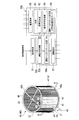
- the heliostat control device 50b of this embodiment is a device that determines a first correction coefficient according to the temperature condition of the heat receiving pipe assembly 45. Therefore, the heat receiving pipe assembly 45 of the present embodiment is provided with a plurality of thermometers 71 and 72 as shown in FIG.
- the inlet pipe 48 of the heat receiving pipe assembly 45 is provided with a heat receiver inlet thermometer 71 that detects the temperature of the air passing through the inlet pipe 48.
- a region outlet thermometer 72 that detects the temperature of the air passing through the one heat receiving tube 47 is provided at the outlet of the one heat receiving tube 47 among the heat receiving tubes 47 in the region a. This area
- region exit thermometer 72 is provided for every some area
- the heliostat control device 50b of the present embodiment includes a load acquisition unit 51, a driving heliostat setting unit 52b, a driving instruction unit 57, and a storage unit 60. .
- the heliostat control device 50b of the present embodiment further includes a temperature acquisition unit 58 that acquires temperatures detected by the heat receiver inlet thermometer 71 and the region outlet thermometer 72.
- the driving heliostat setting unit 52b of the present embodiment includes a driving number calculation unit 53b and a driving heliostat determination unit 54a.
- the number-of-operations calculation unit 53b is a device that determines the first correction coefficient according to the temperature condition of the heat receiving pipe assembly 45, and the processing content is different from that of the second embodiment.
- the storage unit 60 stores a group configuration number 62 and an equivalent number correspondence map 64 for determining an operating heliostat for each of a plurality of heliostat groups A. Further, the storage unit 60 stores identifier correspondence information 66 indicating the correspondence between heliostat group identifiers and region identifiers.
- the operating number calculation unit 53b is a device that determines the first correction coefficient according to the temperature condition of the heat receiving pipe assembly 45
- the first correction coefficient map 61a (FIG. 11) is stored in the storage unit 60. Not remembered.
- the operation number calculation unit 53b of the operation heliostat setting unit 52b performs the load control signal for each of the plurality of heliostat groups A.
- the operating number calculating unit 53b first receives a turbine load from the load acquiring unit 51 as shown in the flowchart of FIG. 15 (S10). Next, the operating number calculation unit 53b determines whether or not it is a temperature reception timing (S11). This temperature reception timing comes every predetermined period.
- the inlet temperature of the heat receiver 40 detected by the heat receiver inlet thermometer 71 from the temperature acquisition unit 58 and the region provided for each of the plurality of regions a The outlet temperature of each region a detected by the outlet thermometer 72 is received and stored temporarily (S12).
- the temperature acquisition part 58 and the operating number calculation part 53b receive the exit temperature of the area
- the operating number calculation unit 53b reads the stored inlet temperature of the heat receiver 40 and the outlet temperature of each region a. (S13).
- the operating number calculation unit 53b obtains a first correction coefficient for each of the plurality of heliostat groups A according to the following (Equation 3) ( S14).
- region a is fundamentally the same as the inlet temperature of the heat receiver 40 detected with the heat receiver inlet thermometer 71, in this embodiment, the inlet temperature of this heat receiver 40 is set to each. It is set as the inlet temperature of the area
- the operating number calculation unit 53b recognizes the outlet temperature of the region a corresponding to a certain heliostat group A, the identifier correspondence information 66 stored in the storage unit 60 is used.
- the operating number calculation unit 53b uses the heliostat group identifier of the heliostat group A from the identifier correspondence information 66 stored in the storage unit 60 as a search key, and the region identifier of the region a corresponding to the heliostat group A To figure out. Then, the number-of-operating-unit calculating unit 53b uses the outlet temperature of the region a associated with this region identifier among the outlet temperatures for each region received from the temperature acquisition unit 57 as the first correction coefficient for the heliostat group A. Used when seeking.
- Equation 3 B is the difference between the outlet temperature of the heat receiver 40 and the inlet / outlet temperature.
- the first correction coefficient related to a certain heliostat group A is that the difference (B) between the outlet temperature and the inlet temperature of the heat receiver 40 is the difference between the outlet temperature and the inlet temperature of the region a corresponding to this heliostat group A.
- the value divided by (A) Therefore, the first correction coefficient of the present embodiment becomes smaller as the difference between the outlet temperature and the inlet temperature in the region a corresponding to the heliostat group A becomes larger.
- the operating number calculation unit 53b multiplies the load by the first correction coefficient and the number of group components, as in the first and second embodiments.
- the number of operating units for each heliostat group A is obtained (S16).
- the operating heliostat determining unit 54a configures the heliostat group A for each heliostat group A as in the second embodiment.
- indicates driving
- the number of heliostats A operating is proportional to the first correction coefficient that decreases as the difference between the outlet temperature and the inlet temperature in the region corresponding to the heliostat group A increases. For this reason, the larger the difference between the outlet temperature and the inlet temperature in the region corresponding to this heliostat group A, the smaller the number of heliostat groups A that are operated. Therefore, in this embodiment, when the difference between the outlet temperature and the inlet temperature in the region corresponding to the heliostat group A is large, the number of operating heliostat groups A corresponding to the region a decreases, and the region a enters the region a. The amount of heat is reduced. Therefore, the difference between the outlet temperature and the inlet temperature in this region a becomes small. Therefore, according to the solar thermal power generation facility of this embodiment, the durability of the heat receiver 40 can be increased.
- the solar thermal power generation facility of this embodiment is a modification of the solar thermal power generation facility of the third embodiment.
- the inlet pipe 48 of the heat receiving pipe assembly 45 of the present embodiment is provided with a heat receiver inlet thermometer 71 that detects the temperature of the air passing through the inlet pipe 48 as shown in FIG. Moreover, the high temperature part thermometer 73 which detects the temperature of the high temperature part assumed to become the highest temperature in the part of the heat receiving pipe 47 in the area
- region a is provided.
- a surface on the ring inner peripheral side for the plurality of heat receiving tubes 47 arranged in a ring shape that is, a surface on the side irradiated with sunlight (hereinafter referred to as the surface).
- 47a) (the light receiving surface) becomes a high temperature.
- the upper part that receives sunlight from the heliostat 10 located near the heat receiver 40 may be at the highest temperature. Therefore, in the present embodiment, the upper portion of the light receiving surface 47a of the heat receiving tube 47 in the region a is a high temperature portion.
- the upper portion of the light receiving surface 47a of the heat receiving tube 47 is a high temperature portion, but the portion may not be a high temperature portion due to the arrangement of the heliostat 10 or the like. For this reason, the portion of the heat receiving pipe 47 that is actually at the highest temperature may be confirmed, and this portion may be used as the high temperature portion.
- the heliostat control device 50c of the present embodiment is similar to the third embodiment in that the load acquisition unit 51, the operation heliostat setting unit 52c, the operation instruction unit 57, and the temperature acquisition unit 58c And a storage unit 60.
- the driving heliostat setting unit 52c of the present embodiment includes a driving number calculation unit 53c and a driving heliostat determination unit 54a.
- the operation content calculation part 53c differs from 3rd embodiment.
- the temperature acquisition part 58c of this embodiment acquires the temperature detected by the heat receiver inlet thermometer 71 and the high temperature part thermometer 73.
- the storage unit 60 stores a group configuration number 62, identifier correspondence information 66, and an equivalent number correspondence map 64 for determining a driving heliostat for each of a plurality of heliostat groups A.
- the operation number calculation unit 53c of the operation heliostat setting unit 52c performs the load control signal for each of the plurality of heliostat groups A.
- the operating number calculating unit 53c When determining the number of operating units, as shown in the flowchart of FIG. 18, the operating number calculating unit 53c first receives a turbine load from the load acquiring unit 51 as in the third embodiment (S10). Next, the operating number calculation unit 53c determines whether or not it is a temperature reception timing (S11).
- the operating number calculation unit 53c detects the inlet temperature of the heat receiver 40 detected by the heat receiver inlet thermometer 71 from the temperature acquisition unit 58c, and the high temperature part temperature provided in each region.
- region detected by the total 73 is received and these are memorize
- the temperature acquisition part 58c and the operating number calculating part 53c receive the temperature of the high temperature part of the said area
- the operating number calculation unit 53c reads the already stored inlet temperature of the heat receiver 40 and the high temperature part temperature of each region. (S13a).
- the number-of-operations calculation unit 53c calculates the first correction coefficient for each of the plurality of heliostat groups A according to the following (Equation 4) ( S14a).
- the inlet temperature of the heat receiver 40 is made into the inlet temperature of each area
- the operating number calculation unit 53c recognizes the high temperature part temperature in the region corresponding to a certain heliostat group A, the identifier correspondence information 66 stored in the storage unit 60 is used.
- the number-of-operations calculation unit 53c uses the heliostat group identifier of the heliostat group A from the identifier correspondence information 66 stored in the storage unit 60 as a search key, and determines the area identifier of the area corresponding to the heliostat group A. To grasp.
- the number-of-operations calculation unit 53c performs the first correction on the heliostat group A with respect to the high-temperature part temperature of the region associated with this region identifier among the high-temperature part temperatures of each region acquired by the temperature acquisition unit 58c. Used when obtaining the coefficient.
- B is an average value of the difference between the high temperature part temperature and the inlet temperature in each region.
- the first correction coefficient related to a certain heliostat group A is a value obtained by dividing this average value (B) by the difference (A) between the high-temperature part temperature and the inlet temperature in the region corresponding to this heliostat group A. . Therefore, the first correction coefficient of the present embodiment becomes smaller as the difference between the high temperature part temperature and the inlet temperature in the region corresponding to the heliostat group A becomes larger.
- the load is multiplied by the first correction coefficient and the number of group components to obtain a plurality of heliostats.
- the number of operating units for each group A is obtained (S16).
- the operating heliostat determining unit 54a performs the heliostat group A for each heliostat group A as in the second and third embodiments.
- indicates driving
- the number of heliostat groups A in operation is proportional to the first correction coefficient that becomes smaller as the difference between the high temperature portion temperature and the inlet temperature in the region a corresponding to the heliostat group A becomes larger. For this reason, the larger the difference between the high temperature part temperature and the inlet temperature in the region a corresponding to the heliostat group A, the smaller the number of heliostat groups A that are operated. Therefore, in this embodiment, when the difference between the high-temperature part temperature and the inlet temperature in the region a is large, the number of operating heliostat groups A corresponding to the region a decreases, and the amount of heat input to the region a decreases. Therefore, the difference between the high temperature part temperature and the inlet temperature in this region a becomes small. Therefore, according to the solar thermal power generation facility of this embodiment, the durability of the heat receiver 40 can be enhanced.
- the solar thermal power generation facility of this embodiment is a modification of the solar thermal power generation facility of the fourth embodiment, and uses a second correction coefficient in addition to the first correction coefficient when obtaining the number of operating units.
- the inlet pipe 48 of the heat receiving pipe assembly 45 of the present embodiment is provided with a heat receiver inlet thermometer 71 that detects the temperature of the air passing through the inlet pipe 48 as shown in FIG. Further, for each of the plurality of regions a, a high-temperature portion thermometer 73 that detects the temperature of the high-temperature portion that is assumed to be the highest among the portions of the heat-receiving tube 47 in the region a, and the heat-receiving tube 47 in the region a A low-temperature part thermometer 74 that detects the temperature of the low-temperature part that is assumed to be the lowest temperature among the parts is provided.
- the upper portion of the light receiving surface 47 a of the heat receiving tube 47 is set as a high temperature portion, and the temperature of this high temperature portion is detected by a high temperature portion thermometer 73.
- the back surface 47b of the heat receiving tube 47 opposite to the light receiving surface 47a does not reach a higher temperature than the light receiving surface 47a.
- the lower part which receives the sunlight from the heliostat 10 which exists in the position far from the heat receiver 40 may become the lowest temperature.
- the lower portion of the back surface 47b of the heat receiving tube 47 in the region is set as a low temperature portion, and the temperature of this low temperature portion is detected by the low temperature portion thermometer 74.
- the lower portion of the back surface 47b of the heat receiving tube 47 is a low temperature portion, but the portion may not be a low temperature portion due to the arrangement of the heliostat 10 or the like. For this reason, the portion of the heat receiving pipe 47 where the lowest temperature is actually confirmed is confirmed, and this portion may be the low temperature portion.
- the heliostat control device 50d of the present embodiment also has a load acquisition unit 51, an operation heliostat setting unit 52d, an operation instruction unit 57, and temperature acquisition, as in the third and fourth embodiments. It has a unit 58d and a storage unit 60.
- the driving heliostat setting unit 52d of the present embodiment includes a driving number calculation unit 53d and a driving heliostat determination unit 54a.
- the operation number calculation unit 53d uses the second correction coefficient in addition to the first correction coefficient when obtaining the operation number, so that the processing content is different from that of the fourth embodiment.
- the temperature acquisition part 58d of this embodiment acquires the temperature detected by the heat receiver inlet thermometer 71, the high temperature part thermometer 73, and the low temperature part thermometer 74.
- the storage unit 60 stores a group configuration number 62, identifier correspondence information 66, and an equivalent number correspondence map 64 for determining a driving heliostat for each of a plurality of heliostat groups A. ing.
- the operation number calculation unit 53d of the operation heliostat setting unit 52d performs the load control signal for each of the plurality of heliostat groups A.
- the operating number calculating unit 53d When determining the number of operating units, the operating number calculating unit 53d first receives a turbine load from the load acquiring unit 51 as in the third and fourth embodiments as shown in the flowchart of FIG. 21 (S10). Next, the operating number calculation unit 53d determines whether or not it is a temperature reception timing (S11).
- the operating unit number calculation unit 53d detects the inlet temperature of the heat receiver 40 detected by the heat receiver inlet thermometer 71 from the temperature acquisition unit 58d and the high-temperature unit provided in each region a.
- region a are received, and these are primary.
- the temperature acquisition unit 58d and the operating unit number calculation unit 53d receive the high temperature part temperature and the low temperature part temperature of the region together with the region identifier.
- the operating number calculation unit 53d has already stored the inlet temperature of the heat receiver 40, the high temperature part temperature of each region a, and The low temperature part temperature is read (S13b).
- the number-of-operations calculating unit 53d obtains the first correction coefficient for each of the plurality of heliostat groups A according to (Equation 4) ( S14a).
- the number-of-operations calculation unit 53d uses the high-temperature part temperature and low-temperature part temperature of each region received in step 12b or the high-temperature part temperature and low-temperature part temperature of each region read out in step 13b. 5), the second correction coefficient for each of the plurality of heliostat groups A is obtained (S15).
- Second correction factor f (high temperature part temperature-low temperature part temperature) ... (Equation 5)
- f is a function that converts (high temperature part temperature ⁇ low temperature part temperature) into a second correction coefficient.
- the function f has a maximum temperature when the temperature difference is 0, and gradually decreases the second correction coefficient as the temperature difference increases.
- the second correction coefficient is a function that makes the minimum 0.
- the relationship between the two for obtaining the second correction coefficient from (high temperature part temperature ⁇ low temperature part temperature) may be expressed using such a function f, or expressed using a map indicating such a relationship. May be. That is, a map showing the relationship as shown in FIG. 22 may be stored in the storage unit 60 in advance, and the second correction coefficient may be obtained from (high temperature part temperature ⁇ low temperature part temperature) using this map.
- the operating number calculation unit 53d multiplies the load by the number of groups constituting the target heliostat group A, and further, step 14a for the target heliostat group A. Multiply the first correction coefficient obtained in step 2 and the second correction coefficient obtained in step 15 to obtain the number of operating units.
- Number of operating units load ⁇ first correction coefficient ⁇ second correction coefficient ⁇ group number of units (Equation 6)
- the operating heliostat determining unit 54a determines the heliostat group A for each heliostat group A as in the second to fourth embodiments.
- the heliostat number of the driving heliostat corresponding to the number of operating units calculated by the operating number calculating unit 53d is determined from among the plurality of heliostats 10 constituting.
- indicates driving
- the number of heliostat groups A in operation is proportional to the second correction coefficient that becomes smaller as the difference between the high temperature part temperature and the low temperature part temperature in the region a corresponding to the heliostat group A increases. For this reason, the larger the difference between the high-temperature part temperature and the low-temperature part temperature in the region a corresponding to this heliostat group A, the smaller the number of heliostat groups A in operation. Therefore, in this embodiment, when the difference between the high-temperature part temperature and the low-temperature part temperature in the region a is large, the number of operating heliostat groups A corresponding to the region a decreases, and the heat input to the region a decreases. . Therefore, the difference between the high temperature part temperature and the low temperature part temperature in this region a becomes small. Therefore, according to the solar thermal power generation facility of this embodiment, the durability of the heat receiver 40 can be further increased.
- the solar thermal power generation facility of the present embodiment is a modification of the solar thermal power generation facility of the fifth embodiment, and limits the value of the first correction coefficient determined by the temperature state of the heat receiver 40 when determining the number of operating units.
- the heat receiving pipe assembly 45 of the present embodiment is provided with a heat receiver inlet thermometer 71, a high temperature thermometer 73 in each region, and a low temperature thermometer 74 as in the fifth embodiment. Yes.
- the heliostat control device 50e of this embodiment includes a load acquisition unit 51, an operation heliostat setting unit 52e, an operation instruction unit 57, a temperature acquisition unit 58d, and a storage unit 60. is doing.
- the driving heliostat setting unit 52e of the present embodiment includes an operating number calculation unit 53e and an operating heliostat determining unit 54a.
- the driving heliostat setting unit 52e of the present embodiment includes a coefficient determination unit 55 that determines whether or not the first correction coefficient obtained by the operating number calculation unit 53e is equal to or greater than a predetermined upper limit value, and this coefficient determination.
- the coefficient changing unit 56 changes the first correction coefficient to a small value.
- the storage unit 60 stores a group configuration number 62, identifier correspondence information 66, and an equivalent number correspondence map 64 for determining a driving heliostat for each of a plurality of heliostat groups A. ing.
- the operation number calculation unit 53e of the operation heliostat setting unit 52e performs the load control signal for each of the plurality of heliostat groups A.
- the operating number calculating unit 53e When determining the number of operating units, as shown in the flowchart of FIG. 24, the operating number calculating unit 53e first receives a turbine load from the load acquiring unit 51 as in the third to fifth embodiments (S10). Next, the operating number calculation unit 53e determines whether it is a temperature reception timing (S11).
- the operating unit number calculation unit 53e detects the inlet temperature of the heat receiver 40 detected by the heat receiver inlet thermometer 71 from the temperature acquisition unit 58d, and the high temperature part temperature provided in each region a.
- the high-temperature part temperature of each region a detected by the total 73 and the low-temperature part temperature of each region a detected by the low-temperature part thermometer 74 provided in each region a are received and stored temporarily. (S12b).
- the number of operating units 53e receives the turbine load from the load acquisition unit 51 and the temperature reception timing is not reached, the stored inlet temperature of the heat receiver 40, the high temperature part temperature of each region a, and The low temperature part temperature is read (S13b).
- the operating number calculation unit 53e obtains the first correction coefficient for each of the plurality of heliostat groups A according to the above (Equation 4) ( S14a).
- the operating number calculation unit 53e uses the high-temperature part temperature and the low-temperature part temperature of each region received in step 12b or the high-temperature part temperature and the low-temperature part temperature of each region read in step 13b. 5), the second correction coefficient for each of the plurality of heliostat groups A is obtained (S15).
- the operating number calculation unit 53e multiplies the load by the first correction coefficient, the second correction coefficient of the target heliostat group A, and the number of group constituents to obtain the operating number (S16).
- the coefficient determining unit 55 determines whether or not the first correction coefficient for each of the plurality of heliostat groups A is equal to or greater than a predetermined upper limit value. Is determined (S17).
- the driving heliostat determining unit 54a corresponds to the number of operating units calculated by the operating unit calculating unit 53e from the plurality of heliostats 10 constituting the heliostat group A for each heliostat group A. Determine the heliostat number of the driving heliostat. And the driving
- the coefficient changing unit 56 changes the first correction coefficient. (S18).
- the coefficient changing unit 56 uses the number of operating units calculated by the operating unit calculating unit 53e and the equivalent number correspondence map 64 for determining the driving heliostat stored in the storage unit 60 in changing the first correction coefficient. As shown in FIG. 25, when the first correction coefficient is equal to or higher than the upper limit value, the number of operating units is “9.1”, and at that time, the heliostat number determined by the equivalent unit correspondence map 64 for determining the operating heliostats. Is “8”. The coefficient changing unit 56 first obtains the maximum operation number “10.5” determined for the heliostat number “8” using the equivalent number correspondence map 64 for determining the operation heliostat.
- the coefficient changing unit 56 divides the operating number “9.1” obtained by the operating number calculating unit 53e by the operating number “10.5” newly obtained by the coefficient changing unit 56 (9.1 / 10.5). Is multiplied by the first correction coefficient obtained in step 14a to obtain a new first correction coefficient. And the coefficient change part 56 transmits this new 1st correction coefficient to the operating number calculating part 53e.
- the operating number calculation unit 53e uses the new first correction coefficient transmitted from the coefficient changing unit 56 to determine again the operating number of the heliostat group A to which the first correction coefficient corresponds (S16).
- the coefficient determining unit 55 determines whether or not the new first correction coefficient of the heliostat group A is equal to or higher than the upper limit value. It is judged again (S17).
- the coefficient changing unit 56 When the new first correction coefficient of the heliostat group A is equal to or higher than the upper limit value, the coefficient changing unit 56 further changes the new first correction coefficient (S18). As shown in FIG. 25, when the number of operating units used to obtain the new first correction coefficient is “10.5”, this operating unit number “64” is determined by the equivalent unit correspondence map 64 for determining the operating heliostat. It is assumed that the heliostat number determined for “10.5” is “9”. The coefficient changing unit 56 obtains the maximum operation number “11.8” determined for the heliostat number “9” using the equivalent number correspondence map 64 for determining the operation heliostat.
- the coefficient changing unit 56 newly calculates a value (10.5 / 11.8) obtained by dividing the previous operating number “10.5” by the operating number “11.8” newly calculated by the coefficient changing unit 56. Multiply the correction coefficient to make this a new new first correction coefficient. And the coefficient change part 56 transmits this further new 1st correction coefficient to the operating number calculating part 53e.
- step 16 to step 18 is repeated until the first correction coefficient becomes smaller than the upper limit value.
- the processing by the operating number calculation unit 53e, the coefficient determination unit 55, and the coefficient change unit 56 ends, and the driving heliostat determination unit 54a
- a heliostat number corresponding to the number of operating helicopters determined by the operating number calculation unit 53e is determined from among the plurality of heliostats 10 constituting the heliostat group A.
- the first correction coefficient obtained by the calculation when the first correction coefficient obtained by the calculation is equal to or higher than the upper limit value, the first correction coefficient is changed to be smaller than the upper limit value. For this reason, in this embodiment, the first correction coefficient obtained by the calculation becomes extremely large, and the number of operating units of the heliostat group A increases, so that the temperature of the region corresponding to the heliostat group A is more than necessary. High temperature can be avoided.
- the first correction coefficient is changed to a small value when the first correction coefficient is equal to or higher than the upper limit value using the equivalent number correspondence map 64 for determining the driving heliostat.
- the first correction coefficient may be changed to a small value by multiplying the first correction coefficient by a predetermined value. Further, the first correction coefficient may be changed to a small value by subtracting a predetermined value from the first correction coefficient. Further, the first correction coefficient may be changed to a value (fixed value) smaller than a predetermined upper limit value.
- the first correction coefficient is determined using the first correction coefficient map 61a.
- the first correction coefficient map 61a has a thermometer attached to the heat receiver 40 as in the third to sixth embodiments, for example, and obtains a first correction coefficient based on the temperature detected by the thermometer.
- the first correction coefficient and the time when the temperature is detected may be associated and stored in the storage unit 60, and the first correction coefficient map 61a may be sequentially corrected.
- the sixth embodiment is a modification of the fifth embodiment, but as in the third and fourth embodiments, when obtaining the first correction coefficient by calculation, as in the sixth embodiment, When the upper limit value is set and the first correction coefficient is equal to or higher than the upper limit value, the first correction coefficient may be changed to be smaller than the upper limit value.
- the temperature distribution in the heat receiver is made uniform, it is possible to avoid that only a part of the heat receiver becomes unnecessarily high, and the durability of the heat receiver is improved. Can do.
Landscapes
- Engineering & Computer Science (AREA)
- Life Sciences & Earth Sciences (AREA)
- Sustainable Development (AREA)
- Sustainable Energy (AREA)
- Chemical & Material Sciences (AREA)
- Combustion & Propulsion (AREA)
- Mechanical Engineering (AREA)
- General Engineering & Computer Science (AREA)
- Physics & Mathematics (AREA)
- Thermal Sciences (AREA)
- Engine Equipment That Uses Special Cycles (AREA)
Abstract
この太陽熱発電設備は、複数の受熱管を有し、受熱管に太陽光が照射されて、受熱管内の空気が加熱される受熱器(40)と、受熱器で加熱された空気で駆動するタービンと、反射鏡で太陽光を反射して受熱器に太陽光を照射できる複数のヘリオスタット(10)と、を備えている。太陽熱発電設備は、複数の受熱管が複数の領域に分けられ、複数の領域毎に、前記領域内の受熱管に太陽光を照射できる複数のヘリオスタットで構成される一のヘリオスタット群が対応している。ヘリオスタット制御装置(50)は、複数のヘリオスタット群毎に、タービン負荷に対応させて前記ヘリオスタット群を構成する複数のへリオスタットのうちで運転ヘリオスタットを定める運転ヘリオスタット設定部(52)と、複数のヘリオスタット群毎の運転ヘリオスタットに対して運転を指示する運転指示部(57)とを備える。
Description
本発明は、太陽光が照射されて内部の流体が加熱される受熱器と、この受熱器で加熱された流体によって駆動するタービンと、反射鏡で太陽光を反射して受熱器に太陽光を照射する複数のヘリオスタットと、を備えている太陽熱発電設備、ヘリオスタットの制御方法、この方法を実行する制御装置に関する。
本願は、2011年3月25日に、日本に出願された特願2011-068549号に基づき優先権を主張し、その内容をここに援用する。
本願は、2011年3月25日に、日本に出願された特願2011-068549号に基づき優先権を主張し、その内容をここに援用する。
太陽熱発電設備としては、例えば、以下の特許文献1に記載の構成がある。
この太陽熱発電設備は、太陽光が照射されて内部の流体が加熱される受熱器と、この受熱器で加熱された流体によって駆動するタービンと、反射鏡で太陽光を反射して受熱器に太陽光を照射する複数のヘリオスタットと、を備えている。
複数のヘリオスタットからの太陽光を受ける受熱器は、必要以上に太陽光で加熱されて、耐久性が低下する可能性がある。このため、特許文献1の太陽熱発電設備では、受熱器の温度又は受熱器内の流体の温度に基づいて、受熱器に出入りする熱量を調整する熱量調整手段を設けている。
しかしながら、上記特許文献1に記載の技術では、受熱器の温度又は受熱器内の流体の温度に基づいて、受熱器に出入りする熱量を調整しても、受熱器内の温度分布のバラツキが生じて、受熱器内の一部のみが必要以上に高温になる可能性がある。このため、上記特許文献1に記載の技術では、受熱器内の一部のみが必要以上に高温になることで、この一部の熱変形が大きくなり、受熱器の耐久性が低下する可能性がある。
そこで、本発明は、受熱器内の温度分布を均一化して、受熱器の耐久性を向上させることができる技術を提供することを目的とする。
本発明の第一の態様によれば、ヘリオスタット制御装置は、
複数の受熱管を有し、前記受熱管に太陽光が照射されて、前記受熱管内の流体が加熱される受熱器と、前記受熱器で加熱された前記流体によって駆動するタービンと、反射鏡を有し、前記反射鏡で太陽光を反射して前記受熱器に太陽光を照射できる複数のヘリオスタットと、を備えている太陽熱発電設備のヘリオスタット制御装置である。
また、前記太陽熱発電設備では、複数の前記受熱管が複数の領域に分けられ、複数の前記領域毎に、前記領域内の前記受熱管に太陽光を照射できる複数の前記ヘリオスタットで構成される一のヘリオスタット群が対応している。また、前記ヘリオスタット制御装置は、
前記タービンの負荷を取得する負荷取得部と、複数の前記ヘリオスタット群毎に、前記タービンの負荷に対応させて前記ヘリオスタット群を構成する複数の前記へリオスタットのうちで運転するヘリオスタットである運転ヘリオスタットを定める運転ヘリオスタット設定部と、前記運転ヘリオスタット設定部で定められた複数の前記ヘリオスタット群毎の前記運転ヘリオスタットに対して運転を指示し、前記運転ヘリオスタットにより、前記運転ヘリオスタットを含む前記ヘリオスタット群に対応している前記領域内の前記受熱管に太陽光を照射させる運転指示部と、を備えている。
複数の受熱管を有し、前記受熱管に太陽光が照射されて、前記受熱管内の流体が加熱される受熱器と、前記受熱器で加熱された前記流体によって駆動するタービンと、反射鏡を有し、前記反射鏡で太陽光を反射して前記受熱器に太陽光を照射できる複数のヘリオスタットと、を備えている太陽熱発電設備のヘリオスタット制御装置である。
また、前記太陽熱発電設備では、複数の前記受熱管が複数の領域に分けられ、複数の前記領域毎に、前記領域内の前記受熱管に太陽光を照射できる複数の前記ヘリオスタットで構成される一のヘリオスタット群が対応している。また、前記ヘリオスタット制御装置は、
前記タービンの負荷を取得する負荷取得部と、複数の前記ヘリオスタット群毎に、前記タービンの負荷に対応させて前記ヘリオスタット群を構成する複数の前記へリオスタットのうちで運転するヘリオスタットである運転ヘリオスタットを定める運転ヘリオスタット設定部と、前記運転ヘリオスタット設定部で定められた複数の前記ヘリオスタット群毎の前記運転ヘリオスタットに対して運転を指示し、前記運転ヘリオスタットにより、前記運転ヘリオスタットを含む前記ヘリオスタット群に対応している前記領域内の前記受熱管に太陽光を照射させる運転指示部と、を備えている。
前記ヘリオスタット制御装置では、複数の受熱管を複数の領域に分けて、領域毎に、前記領域に対応するヘリオスタット群中で、運転するヘリオスタットを負荷に応じて定めている。そのため、受熱器の複数の領域毎の太陽光の照射量を制御でき、複数の領域毎の太陽光の照射量を均一化することができる。よって、前記ヘリオスタット制御装置によれば、受熱器内の温度分布が均一化し、受熱器の一部のみが必要以上に高温になることを避けることができ、受熱器の耐久性を向上させることができる。
本発明の第二の態様によれば、本発明の第一の態様に係るヘリオスタット制御装置において、前記運転ヘリオスタット設定部は、複数の前記ヘリオスタット群毎に、前記タービンの負荷に対応させて前記ヘリオスタット群中で運転するヘリオスタットの台数である運転台数を求める運転台数演算部と、前記ヘリオスタット群を構成する複数の前記ヘリオスタットに対して予め定められた運転優先順位の高いヘリオスタットを優先的に、前記運転台数設定部が定めた前記運転台数に相当する分を、前記運転ヘリオスタットとする運転ヘリオスタット決定部と、を有する。
前記ヘリオスタット制御装置では、運転優先順位の高いヘリオスタットを優先的に、運転台数相当分、運転ヘリオスタットとしている。そのため、より効果的に、受熱器の複数の領域毎の太陽光の照射量を制御することができる。
本発明の第三の態様によれば、本発明の第二の態様に係るヘリオスタット制御装置において、前記運転優先順位は、前記ヘリオスタット群を構成する複数の前記ヘリオスタットのうちで、前記受熱器内の前記流体に対する入熱量の相対的に小さいヘリオスタットが高くなるよう定められている。
前記ヘリオスタット制御装置では、入熱量の小さいヘリオスタットが安定して運転され、逆に入熱量の大きいヘリオスタットが運転/運転除外の対象になり易くなる。そのため、受熱器の複数の領域毎の太陽光の照射量の制御感度を高めることができる。
本発明の第四の態様によれば、本発明の第三の態様に係るヘリオスタット制御装置において、前記ヘリオスタット群を構成する複数のヘリオスタット毎に、前記ヘリオスタットによる前記受熱器内の前記流体に対する入熱量を、前記ヘリオスタット群を構成する全ヘリオスタットによる前記受熱器内の前記流体に対する入熱量で割った値が前記ヘリオスタットの等価台数として予め定められている。そして、前記運転ヘリオスタット決定部は、前記運転優先順位の高い順に前記運転台数分のヘリオスタットに関する前記等価台数を合計した値を等価運転台数とし、前記等価運転台数分だけ、前記優先順位の高いヘリオスタットを優先的に前記運転ヘリオスタットとする。
前記ヘリオスタット制御装置では、各ヘリオスタットの入熱量に応じた各ヘリオスタットの等価台数、及び等価台数を積算した等価運転台数という概念を導入し、個々のヘリオスタットの入熱量を考慮して、最終的な運転台数である等価運転台数を定めている。そのため、ヘリオスタット群に対応する領域中の受熱管への入熱量を目的の入熱量にすることができる。
本発明の第五の態様によれば、本発明の第二から第四の態様のいずれかの態様に係るヘリオスタット制御装置において、前記運転台数演算部は、前記ヘリオスタット群を構成する複数の前記ヘリオスタットの台数に、前記タービンの負荷と予め定められた手順で求められた補正係数とを掛けて、前記ヘリオスタット群の前記運転台数を定める。
本発明の第六の態様によれば、本発明の第五の態様に係るヘリオスタット制御装置は、複数の前記ヘリオスタット群毎の各時での第一補正係数が記憶されている補正係数記憶部を備える。そして、前記運転台数演算部は、前記ヘリオスタット群の前記運転台数を求める際、前記補正係数記憶部に記憶されている前記ヘリオスタット群の第一補正係数のうちで現時点に対応する時の第一補正係数を、前記補正係数の少なくとも一部として用いる。
前記ヘリオスタット制御装置では、ヘリオスタット群毎にその時々で第一補正係数を定めているので、ヘリオスタット群毎にその時々での適切な運転台数を定めることができる。
本発明の第七の態様によれば、本発明の第五の態様に係るヘリオスタット制御装置において、前記太陽熱発電設備は、前記受熱器の複数の前記領域毎の前記流体の入口温度及び出口温度を検出する温度検出部を備える。そして、前記運転台数演算部は、前記ヘリオスタット群の前記運転台数を求める際、複数の前記領域毎の前記入口温度及び前記出口温度で定まる前記受熱器の入口温度と出口温度との差を、前記ヘリオスタット群に対応する前記領域における前記入口温度と前記出口温度との差で割った値を第一補正係数とし、前記第一補正係数を前記補正係数の少なくとも一部として用いる。
前記ヘリオスタット制御装置では、ヘリオスタット群に対応する領域の出口温度と入口温度の差が大きい場合、この領域に対応するヘリオスタット群の運転台数が少なくなり、この領域への入熱量を少なくすることができる。このため、前記ヘリオスタット制御装置では、この領域の出口温度と入口温度との差を小さくすることができ、受熱器の耐久性を高めることができる。
本発明の第八の態様によれば、本発明の第五の態様に係るヘリオスタット制御装置において、前記太陽熱発電設備は、前記受熱器の複数の前記領域毎の前記流体の入口温度、及び複数の前記領域毎で最も高温になると想定される部分の温度である高温部温度を検出する温度検出部を備える。そして、前記運転台数演算部は、前記ヘリオスタット群の前記運転台数を求める際、複数の前記領域毎の前記入口温度と前記高温部温度との差の平均値を、前記ヘリオスタット群に対応する前記領域における前記入口温度と前記高温部温度との差で割った値を第一補正係数とし、前記第一補正係数を前記補正係数の少なくとも一部として用いる。
前記ヘリオスタット制御装置では、ヘリオスタット群に対応する領域の高温部温度と入口温度の差が大きい場合、この領域に対応するヘリオスタット群の運転台数が少なくなり、この領域への入熱量を少なくすることができる。このため、前記ヘリオスタット制御装置では、この領域の高温部温度と入口温度との差を小さくすることができ、受熱器の耐久性を高めることができる。
本発明の第九の態様によれば、本発明の第七または第八の態様のいずれかの態様に係るヘリオスタット制御装置において、前記運転ヘリオスタット設定部は、前記第一補正係数が予め定められた上限値以上であるか否かを判断する係数判断部と、前記係数判断部で前記第一補正係数が前記上限値以上であると判断されると、前記第一補正係数を予め定められた方法で前記上限値未満に変更する係数変更部と、を有する。そして、前記運転台数演算部は、前記第一補正係数を定めた後、前記係数変更部により前記第一補正係数が変更されると、変更された前記第一補正係数を前記補正係数の一部とする。
前記ヘリオスタット制御装置では、演算で求めた第一補正係数が極端に大きくなり、ヘリオスタット群の運転台数が多くなる。そのため、このヘリオスタット群に対応する領域の温度が必要以上に高温になることを避けることができる。
本発明の第十の態様によれば、本発明の第五から第九の態様のいずれかの態様に係るヘリオスタット制御装置において、前記太陽熱発電設備は、前記受熱管に関する複数の前記領域毎に、前記領域内で最も高温になると想定される部分の温度である高温部温度、及び前記領域内で最も低い温度なると想定される部分の温度である低温部温度を検出する温度検出部を備える。そして、前記運転台数演算部は、前記ヘリオスタット群の前記運転台数を求める際、前記ヘリオスタット群に対応する前記領域における前記高温部温度と前記低温部温度との差に応じて第二補正係数を定め、前記第二補正係数を前記補正係数の少なくとも一部とする。
前記ヘリオスタット制御装置では、ヘリオスタット群に対応する領域の高温部温度と低温部温度の差が大きい場合、この領域に対応するヘリオスタット群の運転台数が少なくなり、この領域への入熱量を少なくすることができる。このため、前記ヘリオスタット制御装置では、この領域の高温部温度と低温部温度との差を小さくすることができ、受熱器の耐久性を高めることができる。
本発明の第十一の態様によれば、太陽熱発電設備は、
本発明の第一から第十の態様のいずれかの態様に係るヘリオスタット制御装置と、前記受熱器と、前記タービンと、前記複数のヘリオスタットと、を備える。
本発明の第一から第十の態様のいずれかの態様に係るヘリオスタット制御装置と、前記受熱器と、前記タービンと、前記複数のヘリオスタットと、を備える。
前記太陽熱発電設備は、本発明の第一から第十の態様のいずれかの態様に係るヘリオスタット制御装置を備えている。そのため、受熱器内の温度分布が均一化し、受熱器の一部のみが必要以上に高温になることを避けることができ、受熱器の耐久性を向上させることができる。
本発明の第十二の態様によれば、本発明の第十一の態様に係る太陽熱発電設備において、複数の前記ヘリオスタットの少なくとも一部は、前記受熱器を中心として周方向に配置される。さらに、複数の前記ヘリオスタット群のうち、少なくとも一部のヘリオスタット群は、前記受熱器を中心とした周方向の位置が異なる。
本発明の第十三の態様によれば、本発明の第十一または第十二の態様のいずれかの態様に係る太陽熱発電設備において、複数の前記ヘリオスタットの少なくとも一部は、前記受熱器に対して遠近方向に配置される。さらに、複数の前記ヘリオスタット群のうち、少なくとも一部のヘリオスタット群は、前記受熱器に対して遠近方向の位置が異なる。
本発明の第十四の態様によれば、本発明の第十一から第十三の態様のいずれかの態様に係る太陽熱発電設備において、複数の前記ヘリオスタット群のうち、隣り合っているヘリオスタット群は、それぞれを構成する複数の前記ヘリオスタットのうちの一部を共有する。
本発明の第十五の態様によれば、ヘリオスタット制御方法は、
複数の受熱管を有し、前記受熱管に太陽光が照射されて、前記受熱管内の流体が加熱される受熱器と、前記受熱器で加熱された前記流体によって駆動するタービンと、反射鏡を有し、前記反射鏡で太陽光を反射して前記受熱器に太陽光を照射できる複数のヘリオスタットと、を備えている太陽熱発電設備のヘリオスタット制御方法である。
また、前記太陽熱発電設備では、複数の前記受熱管が複数の領域に分けられ、複数の前記領域毎に、前記領域内の前記受熱管に太陽光を照射できる複数の前記ヘリオスタットで構成される一のヘリオスタット群が対応している。また、ヘリオスタット制御方法は、
前記タービンの負荷を取得する負荷取得工程と、複数の前記ヘリオスタット群毎に、前記タービンの負荷に対応させて前記ヘリオスタット群を構成する複数の前記ヘリオスタットのうちで運転するヘリオスタットである運転ヘリオスタットを定める運転ヘリオスタット設定工程と、前記運転ヘリオスタット設定工程で定められた複数の前記ヘリオスタット群毎の前記運転ヘリオスタットに対して運転を指示し、前記運転ヘリオスタットにより、前記運転ヘリオスタットを含む前記ヘリオスタット群に対応している前記領域内の前記受熱管に太陽光を照射させる運転指示工程と、を有する。
複数の受熱管を有し、前記受熱管に太陽光が照射されて、前記受熱管内の流体が加熱される受熱器と、前記受熱器で加熱された前記流体によって駆動するタービンと、反射鏡を有し、前記反射鏡で太陽光を反射して前記受熱器に太陽光を照射できる複数のヘリオスタットと、を備えている太陽熱発電設備のヘリオスタット制御方法である。
また、前記太陽熱発電設備では、複数の前記受熱管が複数の領域に分けられ、複数の前記領域毎に、前記領域内の前記受熱管に太陽光を照射できる複数の前記ヘリオスタットで構成される一のヘリオスタット群が対応している。また、ヘリオスタット制御方法は、
前記タービンの負荷を取得する負荷取得工程と、複数の前記ヘリオスタット群毎に、前記タービンの負荷に対応させて前記ヘリオスタット群を構成する複数の前記ヘリオスタットのうちで運転するヘリオスタットである運転ヘリオスタットを定める運転ヘリオスタット設定工程と、前記運転ヘリオスタット設定工程で定められた複数の前記ヘリオスタット群毎の前記運転ヘリオスタットに対して運転を指示し、前記運転ヘリオスタットにより、前記運転ヘリオスタットを含む前記ヘリオスタット群に対応している前記領域内の前記受熱管に太陽光を照射させる運転指示工程と、を有する。
前記ヘリオスタット制御方法では、複数の受熱管を複数の領域に分けて、領域毎に、前記領域に対応するヘリオスタット群中で、運転するヘリオスタットを負荷に応じて定めている。そのため、受熱器の複数の領域毎の太陽光の照射量を制御でき、複数の領域毎の太陽光の照射量を均一化することができる。よって、前記ヘリオスタット制御方法によれば、受熱器内の温度分布が均一化し、受熱器の一部のみが必要以上に高温になることを避けることができ、受熱器の耐久性を向上させることができる。
上記によれば、受熱器内の温度分布が均一化し、受熱器の一部のみが必要以上に高温になることを避けることができ、受熱器の耐久性を向上させることができる。
以下、本発明の実施形態に係る太陽熱発電設備について、図面を参照して詳細に説明する。
「第一実施形態」
まず、図1~図10を参照して、本発明の第一実施形態に係る太陽熱発電設備について説明する。
まず、図1~図10を参照して、本発明の第一実施形態に係る太陽熱発電設備について説明する。
本実施形態の太陽熱発電設備は、図1に示すように、太陽光が照射される受熱器40を有するタワー施設20と、反射鏡11で太陽光を反射して受熱器40に太陽光を照射する複数のヘリオスタット10と、複数のヘリオスタット10を制御するヘリオスタット制御装置50と、を備えている。
ヘリオスタット10は、太陽光を反射する反射鏡11と、反射鏡11を支持する支持脚12と、反射鏡11を目的の方向に向ける駆動制御器13と、を有している。このヘリオスタット10は、図2に示すように、タワー施設20を中心として、リング状の領域内に複数点在している。言い換えると、ヘリオスタット10は、タワー施設20を中心として、周方向に360°複数配置されていると共に、タワー施設20を基準として遠近方向にも複数配置されている。
タワー施設20は、図3に示すように、前述の受熱器40と、受熱器40に空気を供給する圧縮機31と、受熱器40で加熱された空気(流体)によって駆動するガスタービン32と、ガスタービン32の駆動により発電する発電機33と、圧縮機31で圧縮された空気とガスタービン32から排気された空気との間で熱交換を行う再生熱交換器34と、これらが収納される収納庫25と、これらが載るタワー21と、を備えている。
タワー21は、鉛直方向に延びる4本の支柱22と、4本の支柱22を相互に連結する複数の梁23とを有している。4本の支柱22の対角線の延長線上には、図2に示すように、ヘリオスタット10は配置されていない。これは、ヘリオスタット10の反射鏡11で反射されて受熱器40に向う太陽光の光路上に、タワー21の支柱22が存在することを避けるためである。また、タワー21の複数の梁23も、ヘリオスタット10の反射鏡11で反射されて受熱器40に向う太陽光の光路上に存在しないよう、配置されている。
収納庫25の内部には、下部収納室26及び上部収納室28が形成されている。下部収納室26の下部には、太陽光を下部収納室26内に取り込むための円形の開口27が形成されている。この下部収納室26には、受熱器40が収納されている。また、上部収納室28には、圧縮機31とガスタービン32と発電機33と再生熱交換器34とが収納されている。
圧縮機31と受熱器40とは、再生熱交換器34を介して、圧縮機31により圧縮された空気を受熱器40に導く圧縮空気供給配管35で接続されている。受熱器40とガスタービン32とは、受熱器40で加熱された空気をガスタービン32に送る加熱空気供給配管36で接続されている。ガスタービン32と再生熱交換器34とは、ガスタービン32からの排気を再生熱交換器34に送る排気配管37で接続されている。
受熱器40は、図4~図6に示すよう、円筒形状のケーシング41と、このケーシング41内に収納される受熱管アッセンブリ45と、有している。
ケーシング41は、側周壁板42と天板43とを有している。ケーシング41の下側には円形の開口44が形成されている。このケーシング41の開口44及び前述の収納庫25の開口27は、いずれも、太陽光線のスポット径よりも僅かに大きく形成されている。ケーシング41の内面には、熱エネルギーの外部へ放射を抑えるために断熱材が設けられている。このケーシング41は、収納庫25の下部収納室26と上部収納室28とを仕切る仕切壁29に固定されているフック39により、この仕切壁29から吊下げられている。このフック39の下端は、ケーシング41の天板43を貫通して、受熱管アッセンブリ45に取り付けられている。すなわち、受熱器40のケーシング41のみならず、受熱管アッセンブリ45も、このフック39により仕切壁29から吊下げられている。
受熱管アッセンブリ45は、リング状に形成された下部ヘッダ配管46aと、同じくリング状に形成された上部ヘッダ配管46bと、鉛直方向に延び下部ヘッダ配管46aと上部ヘッダ配管46bとをつなぐ複数の受熱管47と、圧縮機31からの空気を下部ヘッダ配管46aへ送る入口配管48と、上部ヘッダ配管46bからの空気をガスタービン32へ送るための出口配管49と、を有している。
複数の受熱管47は、リング状の下部ヘッダ配管46a及び上部ヘッダ配管46bの周方向において、所定の間隔をあけて配置されている。ヘリオスタット10からの太陽光は、基本的に、この受熱管47に照射される。そして、受熱管47は高温に上昇する。このように、受熱管47は高温に上昇するため、受熱管47に対して自重による曲げ応力が作用しないよう、受熱管47は、前述したように、鉛直方向に延びている。
下部ヘッダ配管46aは、ケーシング41よりも外周側に位置しており、ケーシング41内に収納されていない。この下部ヘッダ配管46aの外周側には、複数の入口配管48が接続されている。この複数の入口配管48は、圧縮機31から延びる圧縮空気供給配管35に接続されている。また、上部ヘッダ配管46bの内周側には、リング状の上部ヘッダ配管46bの対向部をつなぐように複数の出口配管49が接続されている。複数の出口配管49が相互に交差する部分には、受熱管アッセンブリ45からの空気をガスタービン32に送るための加熱空気供給配管36が接続されている。
周方向に並んでいる複数の受熱管47は、例えば、図7Aに示すように、周方向に複数の領域a1,a2,…,ai,…に分けられている。これら領域a1,a2,…,ai,…には、それぞれ領域識別子が設定されている。
また、複数のヘリオスタット10が配置されている領域は、例えば、図7Bに示すように、タワー施設20を中心とした周方向に複数の部分領域に分けられている。各部分領域には、複数のヘリオスタット10が配置されている。この部分領域内の複数のヘリオスタット10で1つのヘリオスタット群Aが構成されている。複数の部分領域毎のヘリオスタット群A1,A2,…,Ai,…にも、それぞれヘリオスタット群識別子が設定されている。なお、ヘリオスタット群Aの数は受熱管47に関する領域aの数と同じである。また、ヘリオスタット群Aを構成する複数のヘリオスタット10には、それぞれヘリオスタット番号(識別子)が設定されている。
ヘリオスタット群Aは、受熱管47に関する複数の領域aのうち、前記ヘリオスタット群Aを構成する複数のヘリオスタット10で、領域内の複数の受熱管47に太陽光を照射できる前記領域aと、対応付けられている。例えば、受熱器40中の領域a1内の複数の受熱管47には、受熱器40の中心を基準として反対側に位置しているヘリオスタット群A1を構成する複数のヘリオスタット10が太陽光を照射することができる。このため、この領域a1に対して太陽光を照射できるこのヘリオスタット群A1が対応付けられている。
ところで、図7A及び図7Bの例では、ヘリオスタット群Aを構成する複数のヘリオスタット10は、いずれも、隣のヘリオスタット群Aを構成する複数のヘリオスタット10と異なる。しかしながら、ヘリオスタット群Aを構成する複数のヘリオスタット10の一部は、図8A及び図8Bに示すように、隣のヘリオスタット群Aを構成する複数のヘリオスタット10の一部を構成してもよい。言い換えると、隣り合っているヘリオスタット群A1,A2は、それぞれを構成する複数のヘリオスタット10のうちの一部を共有してもよい。この場合、2つのヘリオスタット群A1,A2の両方に属するヘリオスタット10aは、受熱管47に関する2つの領域a1,a2に対して太陽光を照射する。
また、図7A、図7B、図8A及び図8Bに示す例では、受熱管47に関する領域aを周方向に分けている。しかし、図9A及び図9Bに示すように、上下方向、つまり受熱管47内の空気の流れ方向に領域aを分けてもよい。この場合、対応する複数のヘリオスタット群Aは、タワー施設20を基準にして遠近方向に並ぶ。そして、最も下側の領域a11には、タワー施設20から最も遠い側のヘリオスタット群A11が対応する。なお、この場合も、図8A及び図8Bの例と同様、ヘリオスタット群Aを構成する複数のヘリオスタット10の一部が、隣のヘリオスタット群Aを構成する複数のヘリオスタット10の一部を構成してもよい。
ヘリオスタット制御装置50は、図1に示すように、ガスタービン32の負荷を示す負荷制御信号を取得する負荷取得部51と、複数のヘリオスタット10のうちで運転するヘリオスタット10(以下、運転ヘリオスタットとする)を定める運転ヘリオスタット設定部52と、運転ヘリオスタットに運転指示する運転指示部57と、各種データが記憶されている記憶部60と、を有している。
運転ヘリオスタット設定部52は、複数のヘリオスタット群A毎にガスタービン32の負荷に応じたヘリオスタット10の運転台数を求める運転台数演算部53と、ヘリオスタット群Aを構成する複数のヘリオスタット10のうち、この運転台数演算部53が求めた運転台数分のヘリオスタット10を運転ヘリオスタットとする運転ヘリオスタット決定部54と、を有している。
記憶部60には、運転台数演算部53がヘリオスタット10の運転台数を求める際に用いる第一補正係数61と、ヘリオスタット群Aを構成するヘリオスタット10の全台数である群構成台数62と、運転ヘリオスタット決定部54が運転ヘリオスタットを定める際に用いる運転ヘリオスタット決定用マップ63と、が記憶されている。
記憶部60には、第一補正係数61、群構成台数62及び運転ヘリオスタット決定用マップ63のいずれもが、ヘリオスタット群A毎に記憶されている。
運転ヘリオスタット決定用マップ63は、図10に示すように、ヘリオスタット群Aを構成する複数のヘリオスタット10のうちで運転するヘリオスタット10の運転台数と、運転ヘリオスタットのヘリオスタット番号との関係が示されているマップである。
ヘリオスタット群Aを構成する各ヘリオスタット10に付されているヘリオスタット番号は、運転優先順位に応じて定められている。運転優先順位は、受熱器40内の空気に対する入熱量が相対的に小さいヘリオスタット10ほど高い。このため、本実施形態では、受熱器40内の空気に対して小さな受熱器40内の空気に対する入熱量が相対的に小さく、運転優先順位が高いヘリオスタット10に対して、小さな数値のヘリオスタット番号が付されている。具体的には、ヘリオスタット群Aを構成する複数のヘリオスタット10のうち、受熱器40内の空気に対する入熱量が最も小さく、最も優先順位が高いヘリオスタット10には、ヘリオスタット番号「1」が付され、次に入熱量が小さいヘリオスタット10にはヘリオスタット番号「2」が付されている。例えば、図7A及び図7Bに示すヘリオスタット群Aを構成する複数のヘリオスタット10では、タワー施設20から最も遠いヘリオスタット10が受熱器40内の空気に対する入熱量が最も小さい。そのため、タワー施設20から最も遠いヘリオスタット10にヘリオスタット番号「1」が付されている。
なお、本実施形態では、運転優先順位を入熱量の小さい順に定めているが、運転優先順位を受熱管温度に与える影響の小さい順に定めてもよい。但し、運転優先順位を入熱量の小さい順に定めても、受熱管温度に与える影響の小さい順に定めても、定まる運転優先順位に大きな違いは無く基本的に同じである。
また、本実施形態では、ヘリオスタット10の運転優先順位とヘリオスタット番号(識別子)とが同じであるが、両者の対応関係を定めておけば両者が同じである必要はない。
次に、本実施形態のヘリオスタット制御装置50の動作について説明する。
ヘリオスタット制御装置50の負荷取得部51が外部からガスタービン32の負荷制御信号を受信すると、運転ヘリオスタット設定部52の運転台数演算部53は、複数のヘリオスタット群A毎に、負荷制御信号が示すガスタービン32の負荷に応じたヘリオスタット10の運転台数を求める。
この際、運転台数演算部53は、運転台数を求めるヘリオスタット群Aの第一補正係数61及び群構成台数62(前記ヘリオスタット群Aを構成するヘリオスタット10の全台数)を記憶部60から抽出し、以下の(数1)に示すように、負荷に、第一補正係数及び群構成台数を掛けて、運転台数を求める。
運転台数=負荷×第一補正係数×群構成台数 ・・・・・・・・・・(数1)
運転台数=負荷×第一補正係数×群構成台数 ・・・・・・・・・・(数1)
運転台数演算部53によりヘリオスタット群A毎の運転台数が求められると、運転ヘリオスタット決定部54は、ヘリオスタット群A毎に、前記ヘリオスタット群Aを構成する複数のヘリオスタット10のうちから運転台数分の運転ヘリオスタットのヘリオスタット番号を定める。
この際、運転ヘリオスタット決定部54は、記憶部60に記憶されている運転ヘリオスタット決定用マップ63のうちで、運転ヘリオスタットを定めるヘリオスタット群Aの運転ヘリオスタット決定用マップ63を参照する。この運転ヘリオスタット決定用マップ63は、図10に示すように、横軸が前記ヘリオスタット群A中の運転台数を示し、縦軸が前記ヘリオスタット群Aを構成するヘリオスタット10のヘリオスタット番号を示す。運転ヘリオスタット決定部54は、例えば、あるヘリオスタット群Aの運転台数が「7.3」の場合、このヘリオスタット群Aの運転ヘリオスタット決定用マップ63を参照して、運転台数「7.3」に対応するヘリオスタット番号「8」を取得し、このヘリオスタット番号「8」以下の運転番号、つまり、ヘリオスタット番号が1,2,3,…,8のヘリオスタット10を運転ヘリオスタットとする。そして、運転ヘリオスタット決定部54は、このヘリオスタット番号「8」より大きい運転番号のヘリオスタット10を運転対象から除外する。
ヘリオスタット番号は、前述したように、運転の優先順位に応じて付されている。このため、運転ヘリオスタット決定部54がヘリオスタット群Aを構成する複数のヘリオスタット10のうちから運転ヘリオスタットとして定めたヘリオスタット10は、運転優先順位が高い。一方、運転対象から除外されたヘリオスタット10は、運転優先順位が低い。
運転優先順位の高いヘリオスタット10は、前述したように、受熱器40内の空気に対する入熱量が小さく、このヘリオスタット10を運転したときとしないときとでの受熱器40の温度変化に対する影響が小さい。逆に、運転優先順位の低いヘリオスタット10は、受熱器40内の空気に対する入熱量が大きく、このヘリオスタット10を運転したときとしないときとでの受熱器40の温度変化に対する影響が大きい。このため、本実施形態では、運転優先順位が高く、受熱器40の温度変化に対する影響が相対的に小さいヘリオスタット10が安定して運転される一方で、運転優先順位が低く、受熱器40の温度変化に対する影響が相対的に大きいヘリオスタット10が運転/運転除外の対象になり易く、ヘリオスタット制御による受熱器40の温度制御の感度を高めることができる。
運転ヘリオスタット決定部54により、各ヘリオスタット群A毎の運転ヘリオスタットのヘリオスタット番号が定められると、運転指示部57は、定められたヘリオスタット番号のヘリオスタット10に対して運転を指示する。この指示を受け取ったヘリオスタット10の駆動制御器13は、太陽光が受熱器40へ向う方向に反射鏡11を向ける。一方、運転の指示を受け取っていないヘリオスタット10の反射鏡11は、太陽光が受熱器40に向わない方向を向いた状態になる。なお、本実施形態では、運転から除外したヘリオスタット10に対して、運転指示部57は、なんら指示を与えていない。しかし、運転指示部57が、運転から除外したヘリオスタット10に対して運転除外の旨を指示してもよい。
運転指示を受けたヘリオスタット10は、太陽光を受熱器40の受熱管47に照射する。このヘリオスタット10が太陽光を照射する受熱管47は、このヘリオスタット10を含むヘリオスタット群Aに対応する領域a内の受熱管47である。例えば、図7A及び図7Bに示すヘリオスタット群A1を構成するヘリオスタット10の一台が運転指示を受けた場合、このヘリオスタット群A1に対応する領域a1内の複数の受熱管47、つまり、受熱器40の中心を基準として、このヘリオスタット群A1と反対側に位置している領域a1内の複数の受熱管47に、太陽光が照射される。
以上、本実施形態では、複数の受熱管47を複数の領域aに分け、各領域aに、前記領域aに対応するヘリオスタット群A中のヘリオスタット10の運転台数を負荷に応じて定めている。そのため、受熱器40の複数の領域a毎の太陽光の照射量を制御でき、複数の領域a毎の太陽光の照射量を均一化することができる。よって、本実施形態では、受熱器40内の温度分布が均一化し、受熱器40の一部のみが必要以上に高温になることを避けることができ、受熱器40の耐久性を向上させることができる。
「第二実施形態」
次に、図11~図13を参照して、太陽熱発電設備の第二実施形態について説明する。
次に、図11~図13を参照して、太陽熱発電設備の第二実施形態について説明する。
本実施形態の太陽熱発電設備は、第一実施形態の太陽熱発電設備に対して、ヘリオスタット制御装置50aの構成のみが異なっている。そこで、以下では、本実施形態のヘリオスタット制御装置50aについて詳細に説明する。
本実施形態のヘリオスタット制御装置50aも、第一実施形態と同様、負荷取得部51と、運転ヘリオスタット設定部52aと、運転指示部57と、記憶部60とを有している。運転ヘリオスタット設定部52aは、第一実施形態と同様、運転台数演算部53aと、運転ヘリオスタット決定部54aとを有している。但し、これら運転台数演算部53a及び運転ヘリオスタット決定部54aは、その処理内容が第一実施形態と異なっている。
記憶部60には、運転台数演算部53aがヘリオスタット10の運転台数を求める際に用いる第一補正係数マップ61aと、ヘリオスタット群Aを構成するヘリオスタット10の全台数である群構成台数62と、運転ヘリオスタット決定部54aが運転ヘリオスタットを定める際に用いる運転ヘリオスタット決定用の等価台数対応マップ64と、が記憶されている。この記憶部60には、第一補正係数マップ61a、群構成台数62及び運転ヘリオスタット決定用の等価台数対応マップ64のいずれもが、ヘリオスタット群A毎に記憶されている。
次に、本実施形態のヘリオスタット制御装置50aの動作について説明する。
本実施形態においても、負荷取得部51が外部からガスタービン32の負荷制御信号を受信すると、運転ヘリオスタット設定部52aの運転台数演算部53aが、複数のヘリオスタット群A毎に、負荷制御信号が示すガスタービン32の負荷に応じたヘリオスタット10の運転台数を求める。
この際、運転台数演算部53aは、まず、運転台数を求めるヘリオスタット群Aの第一補正係数マップ61aを参照して、第一補正係数を定める。
第一補正係数マップ61aは、図12に示すように、時と第一補正係数との関係を示すマップである。この「時」は、例えば、一年間における一週間単位の時であり、マップ61aには、一年間の各週における第一補正係数が示されている。
受熱管47に関する複数の領域aの負荷配分は、太陽の位置に応じて変えることが好ましい。複数の領域aの負荷配分に関する第一補正係数を、太陽の位置に応じて変えるために、この第一補正係数マップ61aには、年間を通じた各時期毎の第一補正係数が示されている。なお、この第一補正係数マップ61aは、年間を通じた各時期毎の第一補正係数を示すが、太陽の位置は一日のうちでも変化するので、さらに、一日の各時刻毎の第一補正係数を示してもよい。
運転台数演算部53aは、この第一補正係数マップ61aを参照して、現時点の第一補正係数を定める。
次に、運転台数演算部53aは、運転台数を求めるヘリオスタット群Aの群構成台数62を記憶部60から抽出する。そして、運転台数演算部53aは、第一実施形態と同様、負荷に、第一補正係数及び群構成台数を掛けて、運転台数を求める。
運転台数演算部53aによりヘリオスタット群A毎の運転台数が求められると、運転ヘリオスタット決定部54aは、ヘリオスタット群A毎に、前記ヘリオスタット群Aを構成する複数のヘリオスタット10のうちから、運転台数演算部53aが求めた運転台数相当分の運転ヘリオスタットのヘリオスタット番号を定める。
この際、運転ヘリオスタット決定部54aは、記憶部60に記憶されている運転ヘリオスタット決定用の等価台数対応マップ64のうちから、運転ヘリオスタットを定めるヘリオスタット群Aの運転ヘリオスタット決定用の等価台数対応マップ64を参照して、ヘリオスタット群A中の運転ヘリオスタットを定める。例えば、あるヘリオスタット群Aの運転台数が例えば「7.3」の場合、運転ヘリオスタット決定部54aは、このヘリオスタット群Aの運転ヘリオスタット決定用の等価台数対応マップ64を参照して、図13に示すように、運転台数演算部53aが定めた運転台数「7.3」に対応するヘリオスタット番号「7」を取得する。さらに、運転ヘリオスタット決定部54aは、このヘリオスタット番号「7」以下の運転番号、つまり、ヘリオスタット番号が1,2,3,…,7のヘリオスタット10を運転ヘリオスタットとし、このヘリオスタット番号「7」より大きい運転番号のヘリオスタット10を運転対象から除外する。
ところで、本実施形態の運転ヘリオスタット決定用の等価台数対応マップ64は、第一実施形態における運転ヘリオスタット決定用マップ63と同様、横軸が前記ヘリオスタット群A中の運転台数を示し、縦軸が前記ヘリオスタット群Aを構成するヘリオスタット10のヘリオスタット番号を示し、運転台数とヘリオスタット番号との関係付けに、等価運転台数という概念を導入して、両者の関係を定めている。
ここで、等価運転台数とは、各ヘリオスタット10の等価台数をヘリオスタット番号順に合計した値である。あるヘリオスタット10の等価台数は、以下の(数2)に示すように、このヘリオスタット10による受熱器40内の空気に対する入熱量を、このヘリオスタット10が属しているヘリオスタット群Aを構成する全ヘリオスタット10による受熱器40内の空気に対する入熱量で割った値である。
等価台数=(ヘリオスタットによる入熱量)/
(ヘリオスタット群中の全ヘリオスタットによる入熱量) ・・(数2)
等価台数=(ヘリオスタットによる入熱量)/
(ヘリオスタット群中の全ヘリオスタットによる入熱量) ・・(数2)
具体的に、ヘリオスタット番号「1」に対応する等価運転台数は、ヘリオスタット番号「1」のヘリオスタット10の等価台数の値である。また、ヘリオスタット番号「2」に対応する等価運転台数は、ヘリオスタット番号「1」のヘリオスタット10の等価台数と、ヘリオスタット番号「2」のヘリオスタット10の等価台数とを合計した値である。また、ヘリオスタット番号「7」に対応する等価運転台数は、ヘリオスタット番号「1」のヘリオスタット10の等価台数と、ヘリオスタット番号「2」のヘリオスタット10の等価台数と、ヘリオスタット番号「3」のヘリオスタット10の等価台数と、ヘリオスタット番号「4」のヘリオスタット10の等価台数と、ヘリオスタット番号「5」のヘリオスタット10の等価台数と、ヘリオスタット番号「7」のヘリオスタット10の等価台数と、を合計した値である。
前述したように、受熱器40内の空気に対する入熱量が小さいヘリオスタット10には小さいヘリオスタット番号が付され、受熱器40内の空気に対する入熱量が大きいヘリオスタット10には大きいヘリオスタット番号が付されている。このため、ヘリオスタット番号が大きくなるに連れて、ヘリオスタット10の等価台数が大きくなる。また、ヘリオスタット番号に対応する等価運転台数は、ヘリオスタット番号が大きくなるに連れて、言い換えると、運転台数が多くなるに連れて、等価台数が大きくなっている分だけ大きくなる。
したがって、図13中の運転台数-等価運転台数グラフ65に示すように、等価運転台数は、運転台数が多くなるに連れて、個々のヘリオスタット10の等価台数分だけ大きくなる。仮に、運転台数演算部53が求めた運転台数が「7.3」であるとすると、この運転台数-等価運転台数グラフ65によれば、等価運転台数は「6.4」になる。
そして、図13に示すように、図10の運転ヘリオスタット決定用マップ63の横軸を等価運転台数に置き換えた運転ヘリオスタット決定用マップ63aにより、先に求めた等価運転台数分の運転ヘリオスタットが定められる。仮に、等価運転台数が「6.4」である場合、この運転ヘリオスタット決定用マップ63aにより、この運転台数「6.4」に対応するヘリオスタット番号「7」が定まり、このヘリオスタット番号「7」以下の運転番号、つまり、ヘリオスタット番号が1,2,3,…,7のヘリオスタット10を運転ヘリオスタットとなる。
本実施形態の運転ヘリオスタット決定用の等価台数対応マップ64は、図13に示すように、運転台数-等価運転台数グラフ65と、運転ヘリオスタット決定用マップ63aとを合成して、等価運転台数を考慮した運転ヘリオスタット決定用マップである。このため、この運転ヘリオスタット決定用の等価台数対応マップ64を用いることにより、運転台数演算部53が求めた運転台数から、直ちに、等価運転台数を考慮したヘリオスタット番号を定めることができる。
運転ヘリオスタット決定部54aにより、各ヘリオスタット群A毎の運転ヘリオスタットのヘリオスタット番号が定められると、運転指示部57は、第一実施形態と同様、定められたヘリオスタット番号のヘリオスタット10に対して運転を指示する。
以上、本実施形態では、ヘリオスタット群A毎にその時々で第一補正係数を定めているので、ヘリオスタット群A毎にその時々での適切な運転台数を求めことができる。また、本実施形態では、各ヘリオスタット10の入熱量に応じた各ヘリオスタット10の等価台数、及び等価台数を積算した等価運転台数という概念を導入し、個々のヘリオスタット10の入熱量を考慮して、最終的な運転台数(等価運転台数)を定めているので、ヘリオスタット群Aに対応する領域中の受熱管47への入熱量を目的の入熱量にすることができる。
よって、本実施形態では、第一実施形態よりも、ヘリオスタット群A毎に対応する領域a中の受熱管47への入熱量を適切に制御することができ、受熱器40内の温度分布をより均一化することができる。
「第三実施形態」
次に、図14及び図15を参照して、太陽熱発電設備の第三実施形態について説明する。
次に、図14及び図15を参照して、太陽熱発電設備の第三実施形態について説明する。
本実施形態のヘリオスタット制御装置50bは、受熱管アッセンブリ45の温度状況に応じた第一補正係数を定める装置である。このため、本実施形態の受熱管アッセンブリ45には、図14に示すように、複数の温度計71,72が設けられている。
受熱管アッセンブリ45の入口配管48には、入口配管48を通る空気の温度を検知する受熱器入口温度計71が設けられている。また、領域a内の受熱管47のうち一の受熱管47の出口部には、一の受熱管47を通る空気の温度を検知する領域出口温度計72が設けられている。この領域出口温度計72は、複数の領域a毎に設けられている。
本実施形態のヘリオスタット制御装置50bは、第一及び第二実施形態と同様、負荷取得部51と、運転ヘリオスタット設定部52bと、運転指示部57と、記憶部60とを有している。本実施形態のヘリオスタット制御装置50bは、さらに、受熱器入口温度計71及び領域出口温度計72で検知された温度を取得する温度取得部58を有している。本実施形態の運転ヘリオスタット設定部52bは、第二実施形態と同様、運転台数演算部53bと、運転ヘリオスタット決定部54aとを有している。但し、運転台数演算部53bは、前述したように、受熱管アッセンブリ45の温度状況に応じた第一補正係数を定める装置であり、その処理内容が第二実施形態と異なっている。
記憶部60には、第二実施形態と同様、群構成台数62と運転ヘリオスタット決定用の等価台数対応マップ64とが、複数のヘリオスタット群A毎に記憶されている。さらに、この記憶部60にはヘリオスタット群識別子と領域識別子との対応関係を示す識別子対応情報66が記憶されている。一方、前述したように、運転台数演算部53bが受熱管アッセンブリ45の温度状況に応じた第一補正係数を定める装置であるため、記憶部60には第一補正係数マップ61a(図11)は記憶されていない。
次に、本実施形態のヘリオスタット制御装置50bの動作について説明する。
本実施形態においても、負荷取得部51が外部からガスタービン32の負荷制御信号を受信すると、運転ヘリオスタット設定部52bの運転台数演算部53bが、複数のヘリオスタット群A毎に、負荷制御信号が示すガスタービン32の負荷に応じたヘリオスタット10の運転台数を求める。
運転台数演算部53bは、運転台数を求めるにあたり、図15のフローチャートに示すように、まず、負荷取得部51からタービン負荷を受け付ける(S10)。次に、運転台数演算部53bは、温度受付タイミングであるか否かを判断する(S11)。この温度受付タイミングは、予め定められた一定周期毎に訪れる。
運転台数演算部53bは、温度受付タイミングである場合には、温度取得部58から受熱器入口温度計71で検知された受熱器40の入口温度と、複数の領域a毎に設けられている領域出口温度計72で検知された各領域aの出口温度とを受け付けて、これらを一次的に記憶する(S12)。なお、温度取得部58及び運転台数演算部53bは、領域識別子と共にこの領域識別子が示す領域の出口温度を受け付ける。一方、運転台数演算部53bは、負荷取得部51からタービン負荷を受け付けたときに、温度受付タイミングでない場合には、既に記憶してある受熱器40の入口温度及び各領域aの出口温度を読み出す(S13)。
次に、運転台数演算部53bは、ステップ12で受け付けた温度又はステップ13で読み出した温度を用いて、以下の(数3)により、複数のヘリオスタット群A毎の第一補正係数を求める(S14)。
第一補正係数=B/A ・・・・・・・・・・・・・・・・・・・・(数3)
A:領域の出口温度-領域の入口温度
B:(Σ(領域の出口温度-領域の入口温度))/領域数
A:領域の出口温度-領域の入口温度
B:(Σ(領域の出口温度-領域の入口温度))/領域数
なお、各領域aの入口温度は、基本的に、受熱器入口温度計71で検知された受熱器40の入口温度と同じであるため、本実施形態では、この受熱器40の入口温度を各領域aの入口温度としている。また、運転台数演算部53bは、あるヘリオスタット群Aに対応する領域aの出口温度を認識する際、記憶部60に記憶されている識別子対応情報66を用いる。運転台数演算部53bは、記憶部60に記憶されている識別子対応情報66のうちから、ヘリオスタット群Aのヘリオスタット群識別子を検索キーとして、このヘリオスタット群Aに対応する領域aの領域識別子を把握する。そして、運転台数演算部53bは、温度取得部57から受け付けた領域毎の出口温度のうち、この領域識別子と対応付けられている領域aの出口温度を、このヘリオスタット群Aに関する第一補正係数を求める際に用いる。
ここで、(数3)において、Bは、受熱器40の出口温度と入口出口温度との差である。このため、あるヘリオスタット群Aに関する第一補正係数は、受熱器40の出口温度と入口温度との差(B)を、このヘリオスタット群Aに対応する領域aの出口温度と入口温度の差(A)で割った値となる。よって、本実施形態の第一補正係数は、ヘリオスタット群Aに対応する領域aの出口温度と入口温度の差が大きくなるほど、小さな値になる。
運転台数演算部53bは、複数のヘリオスタット群A毎の第一補正係数を求めると、第一及び第二実施形態と同様、負荷に、第一補正係数及び群構成台数を掛けて、複数のヘリオスタット群A毎の運転台数を求める(S16)。
以上で、運転台数演算部53bによる処理が終了する。
運転台数演算部53bによりヘリオスタット群A毎の運転台数が求められると、運転ヘリオスタット決定部54aは、第二実施形態と同様に、ヘリオスタット群A毎に、前記ヘリオスタット群Aを構成する複数のヘリオスタット10のうちから、運転台数演算部53bが求めた運転台数相当分(=等価運転台数分)の運転ヘリオスタットのヘリオスタット番号を定める。そして、運転指示部57は、定められたヘリオスタット番号のヘリオスタット10に対して運転を指示する。
本実施形態において、ヘリオスタット群Aの運転台数は、ヘリオスタット群Aに対応する領域の出口温度と入口温度の差が大きくなるほど小さな値になる第一補正係数と比例関係にある。このため、このヘリオスタット群Aに対応する領域の出口温度と入口温度の差が大きくなるほど、このヘリオスタット群Aの運転台数が少なくなる。よって、本実施形態では、ヘリオスタット群Aに対応する領域の出口温度と入口温度の差が大きい場合、この領域aに対応するヘリオスタット群Aの運転台数が少なくなり、この領域aへの入熱量が少なくなる。そのため、この領域aの出口温度と入口温度との差は小さくなる。従って、本実施形態太陽熱発電設備によれば、受熱器40の耐久性を高めることができる。
「第四実施形態」
次に、図16~図18を参照して、太陽熱発電設備の第四実施形態について説明する。
次に、図16~図18を参照して、太陽熱発電設備の第四実施形態について説明する。
本実施形態の太陽熱発電設備は、第三実施形態の太陽熱発電設備の変形例である。
本実施形態の受熱管アッセンブリ45の入口配管48には、図16に示すように、入口配管48を通る空気の温度を検知する受熱器入口温度計71が設けられている。また、複数の領域a毎に、領域a内の受熱管47の部分のうちで最も高温になると想定される高温部の温度を検知する高温部温度計73が設けられている。
図17に示すように、受熱管47の部分のうちで、リング状に配置されている複数の受熱管47にとってのリング内周側の面、つまり、太陽光が照射される側の面(以下、受光面とする)47aは、高温になる。また、この受熱管47の受光面47a中で、受熱器40に近い位置に存在するヘリオスタット10からの太陽光を受ける上側の部分は最も高温になる可能性がある。そこで、本実施形態では、領域a内の受熱管47の受光面47a中で上側の部分を高温部としている。なお、本実施形態では、受熱管47の受光面47a中で上側の部分を高温部としているが、ヘリオスタット10の配置等から前記部分が高温部でないこともあり得る。そのため、実際に受熱管47のうちで最も高温になる部分を確認し、この部分を高温部としてもよい。
本実施形態のヘリオスタット制御装置50cは、図16に示すように、第三実施形態と同様、負荷取得部51と、運転ヘリオスタット設定部52cと、運転指示部57と、温度取得部58cと、記憶部60とを有している。本実施形態の運転ヘリオスタット設定部52cは、第三実施形態と同様、運転台数演算部53cと運転ヘリオスタット決定部54aとを有している。但し、運転台数演算部53cは、第一補正係数を求める際に用いる温度が第三実施形態と異なるため、その処理内容が第三実施形態と異なる。また、本実施形態の温度取得部58cは、受熱器入口温度計71及び高温部温度計73で検知された温度を取得する。記憶部60には、第三実施形態と同様、群構成台数62、識別子対応情報66、及び運転ヘリオスタット決定用の等価台数対応マップ64が、複数のヘリオスタット群A毎に記憶されている。
次に、本実施形態のヘリオスタット制御装置50cの動作について説明する。
本実施形態においても、負荷取得部51が外部からガスタービン32の負荷制御信号を受信すると、運転ヘリオスタット設定部52cの運転台数演算部53cが、複数のヘリオスタット群A毎に、負荷制御信号が示すガスタービン32の負荷に応じたヘリオスタット10の運転台数を求める。
運転台数演算部53cは、運転台数を求めるにあたり、図18のフローチャートに示すように、第三実施形態と同様、まず、負荷取得部51からタービン負荷を受け付ける(S10)。次に、運転台数演算部53cは、温度受付タイミングであるか否かを判断する(S11)。
運転台数演算部53cは、温度受付タイミングである場合には、温度取得部58cから、受熱器入口温度計71で検知された受熱器40の入口温度と、各領域に設けられている高温部温度計73で検知された各領域の高温部温度とを受け付けて、これらを一次的に記憶する(S12a)。なお、温度取得部58c及び運転台数演算部53cは、領域識別子と共に前記領域の高温部の温度を受け付ける。一方、運転台数演算部53cは、負荷取得部51からタービン負荷を受け付けたときに、温度受付タイミングでない場合には、既に記憶してある受熱器40の入口温度及び各領域の高温部温度を読み出す(S13a)。
次に、運転台数演算部53cは、ステップ12aで受け付けた温度又はステップ13aで読み出した温度を用いて、以下の(数4)により、複数のヘリオスタット群A毎の第一補正係数を求める(S14a)。
第一補正係数=B/A ・・・・・・・・・・・・・・・・・・・・(数4)
A:領域の高温部温度-領域の入口温度
B:(Σ(領域の高温部温度-領域の入口温度))/領域数
A:領域の高温部温度-領域の入口温度
B:(Σ(領域の高温部温度-領域の入口温度))/領域数
なお、本実施形態においても、第三実施形態と同様、受熱器40の入口温度を各領域の入口温度としている。また、運転台数演算部53cは、あるヘリオスタット群Aに対応する領域の高温部温度を認識する際、記憶部60に記憶されている識別子対応情報66を用いる。運転台数演算部53cは、記憶部60に記憶されている識別子対応情報66のうちから、ヘリオスタット群Aのヘリオスタット群識別子を検索キーとして、このヘリオスタット群Aに対応する領域の領域識別子を把握する。そして、運転台数演算部53cは、温度取得部58cが取得した各領域の高温部温度のうち、この領域識別子と対応付けられている領域の高温部温度を、このヘリオスタット群Aに関する第一補正係数を求める際に用いる。
ここで、(数4)において、Bは、各領域の高温部温度と入口温度との差の平均値である。このため、あるヘリオスタット群Aに関する第一補正係数は、この平均値(B)を、このヘリオスタット群Aに対応する領域の高温部温度と入口温度の差(A)で割った値となる。よって、本実施形態の第一補正係数は、ヘリオスタット群Aに対応する領域の高温部温度と入口温度の差が大きくなるほど、小さな値になる。
運転台数演算部53cは、複数のヘリオスタット群A毎の第一補正係数を求めると、以上の各実施形態と同様、負荷に、第一補正係数及び群構成台数を掛けて、複数のヘリオスタット群A毎の運転台数を求める(S16)。
以上で、運転台数演算部53cによる処理が終了する。
運転台数演算部53cによりヘリオスタット群A毎の運転台数が求められると、運転ヘリオスタット決定部54aは、第二及び第三実施形態と同様に、ヘリオスタット群A毎に、前記ヘリオスタット群Aを構成する複数のヘリオスタット10のうちから、運転台数演算部53cが求めた運転台数相当分(=等価運転台数分)の運転ヘリオスタットのヘリオスタット番号を定める。そして、運転指示部57は、定められたヘリオスタット番号のヘリオスタット10に対して運転を指示する。
本実施形態において、ヘリオスタット群Aの運転台数は、ヘリオスタット群Aに対応する領域aの高温部温度と入口温度の差が大きくなるほど小さな値になる第一補正係数と比例関係にある。このため、このヘリオスタット群Aに対応する領域aの高温部温度と入口温度の差が大きくなるほど、このヘリオスタット群Aの運転台数が少なくなる。よって、本実施形態では、領域aの高温部温度と入口温度の差が大きい場合、この領域aに対応するヘリオスタット群Aの運転台数が少なくなり、この領域aへの入熱量が少なくなる。そのため、この領域aの高温部温度と入口温度との差は小さくなる。従って、本実施形態の太陽熱発電設備によれば、受熱器40の耐久性を高めることができる。
「第五実施形態」
次に、図19~図22を参照して、太陽熱発電設備の第五実施形態について説明する。
次に、図19~図22を参照して、太陽熱発電設備の第五実施形態について説明する。
本実施形態の太陽熱発電設備は、第四実施形態の太陽熱発電設備の変形例で、運転台数を求める際、第一補正係数の他に新たに第二補正係数を用いる。
本実施形態の受熱管アッセンブリ45の入口配管48には、図19に示すように、入口配管48を通る空気の温度を検知する受熱器入口温度計71が設けられている。また、複数の領域a毎に、領域a内の受熱管47の部分のうちで最も高温になると想定される高温部の温度を検知する高温部温度計73と、領域a内の受熱管47の部分のうちで最も低い温度になると想定される低温部の温度を検知する低温部温度計74が設けられている。
本実施形態でも、図20に示すように、第四実施形態と同様、受熱管47の受光面47a中で上側の部分を高温部とし、この高温部の温度を高温部温度計73で検知する。また、受熱管47の受光面47aと反対側の裏面47bは、受光面47aに比べて高温にならない。さらに、この裏面47b中で、受熱器40から遠い位置に存在するヘリオスタット10からの太陽光を受ける下側の部分は、最も低い温度になる可能性がある。そこで、本実施形態では、領域内の受熱管47の裏面47b中で下側の部分を低温部として、この低温部の温度を低温部温度計74で検知する。なお、本実施形態では、受熱管47の裏面47b中で下側の部分を低温部としているが、ヘリオスタット10の配置等から前記部分が低温部でないこともあり得る。そのため、実際に受熱管47のうちで最も低い温度になる部分を確認し、この部分を低温部としてもよい。
本実施形態のヘリオスタット制御装置50dも、図19に示すように、第三及び第四実施形態と同様、負荷取得部51と、運転ヘリオスタット設定部52dと、運転指示部57と、温度取得部58dと、記憶部60とを有している。本実施形態の運転ヘリオスタット設定部52dは、第四実施形態と同様、運転台数演算部53dと、運転ヘリオスタット決定部54aとを有している。但し、運転台数演算部53dは、前述したように、運転台数を求める際、第一補正係数の他に第二補正係数を用いるので、その処理内容が第四実施形態と異なる。また、本実施形態の温度取得部58dは、受熱器入口温度計71、高温部温度計73及び低温部温度計74で検知された温度を取得する。記憶部60には、第三及び第四実施形態と同様、群構成台数62、識別子対応情報66、及び運転ヘリオスタット決定用の等価台数対応マップ64が、複数のヘリオスタット群A毎に記憶されている。
次に、本実施形態のヘリオスタット制御装置50dの動作について説明する。
本実施形態においても、負荷取得部51が外部からガスタービン32の負荷制御信号を受信すると、運転ヘリオスタット設定部52dの運転台数演算部53dが、複数のヘリオスタット群A毎に、負荷制御信号が示すガスタービン32の負荷に応じたヘリオスタット10の運転台数を求める。
運転台数演算部53dは、運転台数を求めるにあたり、図21のフローチャートに示すように、第三及び第四実施形態と同様、まず、負荷取得部51からタービン負荷を受け付ける(S10)。次に、運転台数演算部53dは、温度受付タイミングであるか否かを判断する(S11)。
運転台数演算部53dは、温度受付タイミングである場合には、温度取得部58dから、受熱器入口温度計71で検知された受熱器40の入口温度と、各領域aに設けられている高温部温度計73で検知された各領域aの高温部温度と、各領域aに設けられている低温部温度計74で検知された各領域aの低温部温度とを受け付けて、これらを一次的に記憶する(S12b)。なお、温度取得部58d及び運転台数演算部53dは、領域識別子と共に前記領域の高温部温度及び低温部温度を受け付ける。一方、運転台数演算部53dは、負荷取得部51からタービン負荷を受け付けたときに、温度受付タイミングでない場合には、既に記憶してある受熱器40の入口温度、各領域aの高温部温度及び低温部温度を読み出す(S13b)。
次に、運転台数演算部53dは、ステップ12bで受け付けた温度又はステップ13bで読み出した温度を用いて、前述の(数4)により、複数のヘリオスタット群A毎の第一補正係数を求める(S14a)。
次に、運転台数演算部53dは、ステップ12bで受け付けた各領域の高温部温度及び低温部温度、又はステップ13bで読み出した各領域の高温部温度及び低温部温度を用いて、以下の(数5)により、複数のヘリオスタット群A毎の第二補正係数を求める(S15)。
第二補正係数=f(高温部温度-低温部温度) ・・・・・・・・(数5)
なお、(数5)において、fは、(高温部温度-低温部温度)を第二補正係数に変換する関数である。この関数fは、図22に示すように、温度差が0のときに第二補正係数を最大値にし、温度差が大きくなるに連れて次第に第二補正係数を小さな値にし、温度差がある値以上になると第二補正係数を最小の0にする関数である。(高温部温度-低温部温度)から第二補正係数を求めるための両者の関係は、このような関数fを用いて表されてもよいし、このような関係を示すマップを用いて表されてもよい。つまり、図22に示すような関係を示すマップを記憶部60に予め記憶しておき、このマップを用いて、(高温部温度-低温部温度)から第二補正係数を求めてもよい。
最後に、運転台数演算部53dは、以下の(数6)に示すように、負荷に、対象とするヘリオスタット群Aの群構成台数を掛け、さらに、対象とするヘリオスタット群Aに関するステップ14aで求めた第一補正係数及びステップ15で求めた第二補正係数を掛けて、運転台数を求める。
運転台数=負荷×第一補正係数×第二補正係数×群構成台数 ・・・(数6)
運転台数=負荷×第一補正係数×第二補正係数×群構成台数 ・・・(数6)
以上で、運転台数演算部53dによる処理が終了する。
運転台数演算部53dによりヘリオスタット群A毎の運転台数が求められると、運転ヘリオスタット決定部54aは、第二から第四実施形態と同様、ヘリオスタット群A毎に、前記ヘリオスタット群Aを構成する複数のヘリオスタット10のうちから、運転台数演算部53dが求めた運転台数相当分の運転ヘリオスタットのヘリオスタット番号を定める。
そして、運転指示部57は、定められたヘリオスタット番号のヘリオスタット10に対して運転を指示する。
そして、運転指示部57は、定められたヘリオスタット番号のヘリオスタット10に対して運転を指示する。
本実施形態において、ヘリオスタット群Aの運転台数は、ヘリオスタット群Aに対応する領域aの高温部温度と低温部温度の差が大きくなるほど小さな値になる第二補正係数と比例関係にある。このため、このヘリオスタット群Aに対応する領域aの高温部温度と低温部温度の差が大きくなるほど、このヘリオスタット群Aの運転台数が少なくなる。よって、本実施形態では、領域aの高温部温度と低温部温度の差が大きい場合、この領域aに対応するヘリオスタット群Aの運転台数が少なくなり、この領域aへの入熱量が少なくなる。そのため、この領域aの高温部温度と低温部温度との差は小さくなる。従って、本実施形態の太陽熱発電設備によれば、受熱器40の耐久性をさらに高めることができる。
「第六実施形態」
次に、図23~図25を参照して、太陽熱発電設備の第六実施形態について説明する。
次に、図23~図25を参照して、太陽熱発電設備の第六実施形態について説明する。
本実施形態の太陽熱発電設備は、第五実施形態の太陽熱発電設備の変形例で、運転台数を求める際、受熱器40の温度状況により定める第一補正係数の値を制限する。
本実施形態の受熱管アッセンブリ45には、図23に示すように、第五実施形態と同様、受熱器入口温度計71、各領域の高温部温度計73及び低温部温度計74が設けられている。
本実施形態のヘリオスタット制御装置50eは、第五実施形態と同様、負荷取得部51と、運転ヘリオスタット設定部52eと、運転指示部57と、温度取得部58dと、記憶部60とを有している。本実施形態の運転ヘリオスタット設定部52eは、第五実施形態と同様、運転台数演算部53eと、運転ヘリオスタット決定部54aとを有している。さらに、本実施形態の運転ヘリオスタット設定部52eは、運転台数演算部53eが求めた第一補正係数が予め定めた上限値以上であるか否かを判断する係数判断部55と、この係数判断部55により第一補正係数が予め定めた上限値以上であると判断されると、第一補正係数を小さな値に変更する係数変更部56と、を有している。記憶部60には、第三から第五実施形態と同様、群構成台数62、識別子対応情報66、及び運転ヘリオスタット決定用の等価台数対応マップ64が、複数のヘリオスタット群A毎に記憶されている。
次に、本実施形態のヘリオスタット制御装置50eの動作について説明する。
本実施形態においても、負荷取得部51が外部からガスタービン32の負荷制御信号を受信すると、運転ヘリオスタット設定部52eの運転台数演算部53eが、複数のヘリオスタット群A毎に、負荷制御信号が示すガスタービン32の負荷に応じたヘリオスタット10の運転台数を求める。
運転台数演算部53eは、運転台数を求めるにあたり、図24のフローチャートに示すように、第三から第五実施形態と同様、まず、負荷取得部51からタービン負荷を受け付ける(S10)。次に、運転台数演算部53eは、温度受付タイミングであるか否かを判断する(S11)。
運転台数演算部53eは、温度受付タイミングである場合には、温度取得部58dから受熱器入口温度計71で検知された受熱器40の入口温度と、各領域aに設けられている高温部温度計73で検知された各領域aの高温部温度と、各領域aに設けられている低温部温度計74で検知された各領域aの低温部温度を受け付けて、これらを一次的に記憶する(S12b)。一方、運転台数演算部53eは、負荷取得部51からタービン負荷を受け付けたときに、温度受付タイミングでない場合には、既に記憶してある受熱器40の入口温度、各領域aの高温部温度及び低温部温度を読み出す(S13b)。
次に、運転台数演算部53eは、ステップ12bで受け付けた温度又はステップ13bで読み出した温度を用いて、前述の(数4)により、複数のヘリオスタット群A毎の第一補正係数を求める(S14a)。
次に、運転台数演算部53eは、ステップ12bで受け付けた各領域の高温部温度及び低温部温度、又はステップ13bで読み出した各領域の高温部温度及び低温部温度を用いて、前述の(数5)により、複数のヘリオスタット群A毎の第二補正係数を求める(S15)。
次に、運転台数演算部53eは、負荷に、対象とするヘリオスタット群Aの第一補正係数、第二補正係数、さらに群構成台数を掛けて、運転台数を求める(S16)。
運転台数演算部53eにより複数のヘリオスタット群A毎の運転台数が求められると、係数判断部55は、複数のヘリオスタット群A毎の第一補正係数が予め定めた上限値以上であるか否かを判断する(S17)。
複数のヘリオスタット群A毎の第一補正係数のいずれもが上限値以上でなければ、運転台数演算部53e、係数判断部55及び係数変更部56のよる処理が終了し、第二から第五実施形態と同様、運転ヘリオスタット決定部54aが、ヘリオスタット群A毎に、前記ヘリオスタット群Aを構成する複数のヘリオスタット10のうちから、運転台数演算部53eが求めた運転台数相当分の運転ヘリオスタットのヘリオスタット番号を定める。そして、運転指示部57は、定められたヘリオスタット番号のヘリオスタット10に対して運転を指示する。
一方、ステップ17で、係数判断部55が複数のヘリオスタット群A毎の第一補正係数のうちのいずれかが上限値以上であると判断すると、係数変更部56がこの第一補正係数を変更する(S18)。
係数変更部56は、第一補正係数の変更にあたり、運転台数演算部53eが求めた運転台数と記憶部60に記憶されている運転ヘリオスタット決定用の等価台数対応マップ64とを用いる。仮に、図25に示すように、第一補正係数が上限値以上のときの運転台数が「9.1」とし、そのときに、運転ヘリオスタット決定用の等価台数対応マップ64により定めるヘリオスタット番号が「8」であるとする。係数変更部56は、まず、運転ヘリオスタット決定用の等価台数対応マップ64を用いて、このヘリオスタット番号「8」に対して定める最大の運転台数「10.5」を求める。
次に、係数変更部56は、運転台数演算部53eが求めた運転台数「9.1」を係数変更部56が新たに求めた運転台数「10.5」で割った値(9.1/10.5)を、ステップ14aで求められた第一補正係数に掛けて、これを新たな第一補正係数とする。そして、係数変更部56は、この新たな第一補正係数を運転台数演算部53eに送信する。
運転台数演算部53eは、係数変更部56から送信された新たな第一補正係数を用いて、この第一補正係数が対応しているヘリオスタット群Aの運転台数を改めて求める(S16)。
運転台数演算部53eにより、このヘリオスタット群Aの新たに運転台数が求められると、係数判断部55は、このヘリオスタット群Aの新たな第一補正係数が上限値以上であるか否かを再び判断する(S17)。
このヘリオスタット群Aの新たな第一補正係数が上限値以上である場合、係数変更部56は、この新たな第一補正係数をさらに変更する(S18)。仮に、図25に示すように、新たな第一補正係数を得るために用いた運転台数が「10.5」である場合、運転ヘリオスタット決定用の等価台数対応マップ64により、この運転台数「10.5」に対して定めるヘリオスタット番号が「9」であるとする。係数変更部56は、この運転ヘリオスタット決定用の等価台数対応マップ64を用いて、このヘリオスタット番号「9」に対して定める最大の運転台数「11.8」を求める。係数変更部56は、先の運転台数「10.5」を係数変更部56がさらに新たに求めた運転台数「11.8」で割った値(10.5/11.8)を、新たに求めた第一補正係数に掛けて、これを更なる新たな第一補正係数とする。そして、係数変更部56は、この更なる新たな第一補正係数を運転台数演算部53eに送信する。
以上のように、第一補正係数が上限値よりも小さくなるまで、ステップ16~ステップ18の処理を繰り返して行う。そして、第一補正係数が上限値よりも小さくなれば、前述したように、運転台数演算部53e、係数判断部55及び係数変更部56のよる処理が終了し、運転ヘリオスタット決定部54aが、ヘリオスタット群A毎に、前記ヘリオスタット群Aを構成する複数のヘリオスタット10のうちから、運転台数演算部53eが求めた運転台数相当分の運転ヘリオスタットのヘリオスタット番号を定める。
以上のように、本実施形態では、演算で求めた第一補正係数が上限値以上になる場合には、上限値よりも小さくなるよう第一補正係数を変更している。このため、本実施形態では、演算で求めた第一補正係数が極端に大きくなり、ヘリオスタット群Aの運転台数が多くなることで、このヘリオスタット群Aに対応する領域の温度が必要以上に高温になることを避けることができる。
なお、上述の実施形態では、運転ヘリオスタット決定用の等価台数対応マップ64を用いて、第一補正係数が上限値以上の場合、第一補正係数を小さな値に変更しているが、この場合、この第一補正係数に対して予め定めた値を掛けることで、この第一補正係数を小さな値に変更してもよい。また、この第一補正係数から予め定めた値を減算することで、この第一補正係数を小さな値に変更してもよい。また、この第一補正係数を予め定めた上限値よりも小さな値(固定値)に変更してもよい。
「実施形態の変形例」
第二実施形態では、第一補正係数マップ61aを用いて第一補正係数を定めている。この第一補正係数マップ61aは、例えば、第三から第六実施形態のように、受熱器40に温度計を取り付け、この温度計で検知された温度に基づいて第一補正係数を求め、この第一補正係数と温度を検知した時とを関係付けて記憶部60に記憶し、順次、第一補正係数マップ61aを補正するようにしてもよい。
第二実施形態では、第一補正係数マップ61aを用いて第一補正係数を定めている。この第一補正係数マップ61aは、例えば、第三から第六実施形態のように、受熱器40に温度計を取り付け、この温度計で検知された温度に基づいて第一補正係数を求め、この第一補正係数と温度を検知した時とを関係付けて記憶部60に記憶し、順次、第一補正係数マップ61aを補正するようにしてもよい。
また、第六実施形態は、第五実施形態の変形例であるが、第三及び第四実施形態のように、演算で第一補正係数を求める場合には、第六実施形態と同様に、上限値を設定し、第一補正係数が上限値以上になる場合には、上限値よりも小さくなるよう第一補正係数を変更してもよい。
本発明のヘリオスタット制御装置によれば、受熱器内の温度分布が均一化し、受熱器の一部のみが必要以上に高温になることを避けることができ、受熱器の耐久性を向上させることができる。
10…ヘリオスタット
11…反射鏡
20…タワー施設
21…タワー
25…収納庫
31…圧縮機
32…ガスタービン
33…発電機
40…受熱器
41…ケーシング
45…受熱管アッセンブリ
47…受熱管
50,50a,50b,50c,50d,50e…ヘリオスタット制御装置
51…負荷取得部
52,52a,52b,52c,52d,52e…運転ヘリオスタット設定部
53,53a,53b,53c,53d,53e…運転台数演算部
54,54a…運転ヘリオスタット決定部
55…係数判断部
56…係数変更部
57…運転指示部
58,58c,58d…温度取得部
60…記憶部
11…反射鏡
20…タワー施設
21…タワー
25…収納庫
31…圧縮機
32…ガスタービン
33…発電機
40…受熱器
41…ケーシング
45…受熱管アッセンブリ
47…受熱管
50,50a,50b,50c,50d,50e…ヘリオスタット制御装置
51…負荷取得部
52,52a,52b,52c,52d,52e…運転ヘリオスタット設定部
53,53a,53b,53c,53d,53e…運転台数演算部
54,54a…運転ヘリオスタット決定部
55…係数判断部
56…係数変更部
57…運転指示部
58,58c,58d…温度取得部
60…記憶部
Claims (15)
- 複数の受熱管を有し、前記受熱管に太陽光が照射されて、前記受熱管内の流体が加熱される受熱器と、前記受熱器で加熱された前記流体によって駆動するタービンと、反射鏡を有し、前記反射鏡で太陽光を反射して前記受熱器に太陽光を照射できる複数のヘリオスタットと、を備えている太陽熱発電設備のヘリオスタット制御装置であって、
前記太陽熱発電設備は、複数の前記受熱管が複数の領域に分けられ、複数の前記領域毎に、前記領域内の前記受熱管に太陽光を照射できる複数の前記ヘリオスタットで構成される一のヘリオスタット群が対応しており、
前記タービンの負荷を取得する負荷取得部と、
複数の前記ヘリオスタット群毎に、前記タービンの負荷に対応させて前記ヘリオスタット群を構成する複数の前記へリオスタットのうちで運転するヘリオスタットである運転ヘリオスタットを定める運転ヘリオスタット設定部と、
前記運転ヘリオスタット設定部で定められた複数の前記ヘリオスタット群毎の前記運転ヘリオスタットに対して運転を指示し、前記運転ヘリオスタットにより、前記運転ヘリオスタットを含む前記ヘリオスタット群に対応している前記領域内の前記受熱管に太陽光を照射させる運転指示部と、
を備えているヘリオスタット制御装置。 - 請求項1に記載のヘリオスタット制御装置において、
前記運転ヘリオスタット設定部は、複数の前記ヘリオスタット群毎に、前記タービンの負荷に対応させて前記ヘリオスタット群中で運転するヘリオスタットの台数である運転台数を求める運転台数演算部と、前記ヘリオスタット群を構成する複数の前記ヘリオスタットに対して予め定められた運転優先順位の高いヘリオスタットを優先的に、前記運転台数設定部が定めた前記運転台数に相当する分を、前記運転ヘリオスタットとする運転ヘリオスタット決定部と、を有する、
ヘリオスタット制御装置。 - 請求項2記載のヘリオスタット制御装置において、
前記運転優先順位は、前記ヘリオスタット群を構成する複数の前記ヘリオスタットのうちで、前記受熱器内の前記流体に対する入熱量の相対的に小さいヘリオスタットが高くなるよう定められている、
ヘリオスタット制御装置。 - 請求項3に記載のヘリオスタット制御装置において、
前記ヘリオスタット群を構成する複数のヘリオスタット毎に、前記ヘリオスタットによる前記受熱器内の前記流体に対する入熱量を、前記ヘリオスタット群を構成する全ヘリオスタットによる前記受熱器内の前記流体に対する入熱量で割った値が前記ヘリオスタットの等価台数として予め定められており、
前記運転ヘリオスタット決定部は、前記運転優先順位の高い順に前記運転台数分のヘリオスタットに関する前記等価台数を合計した値を等価運転台数とし、前記等価運転台数分だけ、前記優先順位の高いヘリオスタットを優先的に前記運転ヘリオスタットとする、
ヘリオスタット制御装置。 - 請求項2から4のいずれか一項に記載のヘリオスタット制御装置において、
前記運転台数演算部は、前記ヘリオスタット群を構成する複数の前記ヘリオスタットの台数に、前記タービンの負荷と予め定められた手順で求められた補正係数とを掛けて、前記ヘリオスタット群の前記運転台数を求める、
ヘリオスタット制御装置。 - 請求項5に記載のヘリオスタット制御装置において、
複数の前記ヘリオスタット群毎の各時での第一補正係数が記憶されている補正係数記憶部を備え、
前記運転台数演算部は、前記ヘリオスタット群の前記運転台数を求める際、前記補正係数記憶部に記憶されている前記ヘリオスタット群の第一補正係数のうちで現時点に対応する時の第一補正係数を、前記補正係数の少なくとも一部として用いる、
ヘリオスタット制御装置。 - 請求項5に記載のヘリオスタット制御装置において、
前記太陽熱発電設備は、前記受熱器の複数の前記領域毎の前記流体の入口温度及び出口温度を検出する温度検出部を備え、
前記運転台数演算部は、前記ヘリオスタット群の前記運転台数を求める際、複数の前記領域毎の前記入口温度及び前記出口温度で定まる前記受熱器の入口温度と出口温度との差を、前記ヘリオスタット群に対応する前記領域における前記入口温度と前記出口温度との差で割った値を第一補正係数とし、前記第一補正係数を前記補正係数の少なくとも一部として用いる、
ヘリオスタット制御装置。 - 請求項5に記載のヘリオスタット制御装置において、
前記太陽熱発電設備は、前記受熱器の複数の前記領域毎の前記流体の入口温度、及び複数の前記領域毎で最も高温になると想定される部分の温度である高温部温度を検出する温度検出部を備え、
前記運転台数演算部は、前記ヘリオスタット群の前記運転台数を求める際、複数の前記領域毎の前記入口温度と前記高温部温度との差の平均値を、前記ヘリオスタット群に対応する前記領域における前記入口温度と前記高温部温度との差で割った値を第一補正係数とし、前記第一補正係数を前記補正係数の少なくとも一部として用いる、
ヘリオスタット制御装置。 - 請求項7又は8に記載のヘリオスタット制御装置において、
前記運転ヘリオスタット設定部は、前記第一補正係数が予め定められた上限値以上であるか否かを判断する係数判断部と、前記係数判断部で前記第一補正係数が前記上限値以上であると判断されると、前記第一補正係数を予め定められた方法で前記上限値未満に変更する係数変更部と、を有し、
前記運転台数演算部は、前記第一補正係数を定めた後、前記係数変更部により前記第一補正係数が変更されると、変更された前記第一補正係数を前記補正係数の一部とする、
ヘリオスタット制御装置。 - 請求項5から9のいずれか一項に記載のヘリオスタット制御装置において、
前記太陽熱発電設備は、前記受熱管に関する複数の前記領域毎に、前記領域内で最も高温になると想定される部分の温度である高温部温度、及び前記領域内で最も低い温度なると想定される部分の温度である低温部温度を検出する温度検出部を備え、
前記運転台数演算部は、前記ヘリオスタット群の前記運転台数を求める際、前記ヘリオスタット群に対応する前記領域における前記高温部温度と前記低温部温度との差に応じて第二補正係数を定め、前記第二補正係数を前記補正係数の少なくとも一部とする、
ヘリオスタット制御装置。 - 請求項1から10のいずれか一項に記載のヘリオスタット制御装置と、前記受熱器と、前記タービンと、前記複数のヘリオスタットと、
を備える太陽熱発電設備。 - 請求項11に記載の太陽熱発電設備において、
複数の前記ヘリオスタットの少なくとも一部は、前記受熱器を中心として周方向に配置され、
複数の前記ヘリオスタット群のうち、少なくとも一部のヘリオスタット群は、前記受熱器を中心とした周方向の位置が異なっている、
太陽熱発電設備。 - 請求項11又は12に記載の太陽熱発電設備において、
複数の前記ヘリオスタットの少なくとも一部は、前記受熱器に対して遠近方向に配置され、
複数の前記ヘリオスタット群のうち、少なくとも一部のヘリオスタット群は、前記受熱器に対して遠近方向の位置が異なっている、
太陽熱発電設備。 - 請求項10から13のいずれか一項に記載の太陽熱発電設備において、
複数の前記ヘリオスタット群のうち、隣り合っているヘリオスタット群は、それぞれを構成する複数の前記ヘリオスットのうちの一部を共有している、
太陽熱発電設備。 - 複数の受熱管を有し、前記受熱管に太陽光が照射されて、前記受熱管内の流体が加熱される受熱器と、前記受熱器で加熱された前記流体によって駆動するタービンと、反射鏡を有し、前記反射鏡で太陽光を反射して前記受熱器に太陽光を照射できる複数のヘリオスタットと、を備えている太陽熱発電設備のヘリオスタット制御方法であって、
前記太陽熱発電設備は、複数の前記受熱管が複数の領域に分けられ、複数の前記領域毎に、前記領域内の前記受熱管に太陽光を照射できる複数の前記ヘリオスタットで構成される一のヘリオスタット群が対応しており、
前記タービンの負荷を取得する負荷取得工程と、
複数の前記ヘリオスタット群毎に、前記タービンの負荷に対応させて前記ヘリオスタット群を構成する複数の前記ヘリオスタットのうちで運転するヘリオスタットである運転ヘリオスタットを定める運転ヘリオスタット設定工程と、
前記運転ヘリオスタット設定工程で定められた複数の前記ヘリオスタット群毎の前記運転ヘリオスタットに対して運転を指示し、前記運転ヘリオスタットにより、前記運転ヘリオスタットを含む前記ヘリオスタット群に対応している前記領域内の前記受熱管に太陽光を照射させる運転指示工程と、
を有するヘリオスタット制御方法。
Applications Claiming Priority (2)
| Application Number | Priority Date | Filing Date | Title |
|---|---|---|---|
| JP2011-068549 | 2011-03-25 | ||
| JP2011068549A JP2012202630A (ja) | 2011-03-25 | 2011-03-25 | 太陽熱発電設備、この設備に含まれるヘリオスタットの制御方法、この方法を実行する制御装置 |
Publications (1)
| Publication Number | Publication Date |
|---|---|
| WO2012133135A1 true WO2012133135A1 (ja) | 2012-10-04 |
Family
ID=46930862
Family Applications (1)
| Application Number | Title | Priority Date | Filing Date |
|---|---|---|---|
| PCT/JP2012/057425 Ceased WO2012133135A1 (ja) | 2011-03-25 | 2012-03-23 | 太陽熱発電設備、この設備に含まれるヘリオスタットの制御方法、この方法を実行する制御装置 |
Country Status (2)
| Country | Link |
|---|---|
| JP (1) | JP2012202630A (ja) |
| WO (1) | WO2012133135A1 (ja) |
Citations (3)
| Publication number | Priority date | Publication date | Assignee | Title |
|---|---|---|---|---|
| WO2007072591A1 (ja) * | 2006-06-16 | 2007-06-28 | Kawasaki Jukogyo Kabushiki Kaisha | 太陽熱発電設備、熱媒体供給設備および温度変動抑制装置 |
| WO2010013632A1 (ja) * | 2008-07-31 | 2010-02-04 | コスモ石油株式会社 | マルチタワービームダウン式集光システムにおける太陽光の集光方法 |
| JP2011043128A (ja) * | 2009-08-24 | 2011-03-03 | Tokyo Institute Of Technology | 太陽光集光システム |
-
2011
- 2011-03-25 JP JP2011068549A patent/JP2012202630A/ja not_active Withdrawn
-
2012
- 2012-03-23 WO PCT/JP2012/057425 patent/WO2012133135A1/ja not_active Ceased
Patent Citations (3)
| Publication number | Priority date | Publication date | Assignee | Title |
|---|---|---|---|---|
| WO2007072591A1 (ja) * | 2006-06-16 | 2007-06-28 | Kawasaki Jukogyo Kabushiki Kaisha | 太陽熱発電設備、熱媒体供給設備および温度変動抑制装置 |
| WO2010013632A1 (ja) * | 2008-07-31 | 2010-02-04 | コスモ石油株式会社 | マルチタワービームダウン式集光システムにおける太陽光の集光方法 |
| JP2011043128A (ja) * | 2009-08-24 | 2011-03-03 | Tokyo Institute Of Technology | 太陽光集光システム |
Also Published As
| Publication number | Publication date |
|---|---|
| JP2012202630A (ja) | 2012-10-22 |
Similar Documents
| Publication | Publication Date | Title |
|---|---|---|
| US8001960B2 (en) | Method and control system for operating a solar power tower system | |
| CN102741616B (zh) | 利用太阳辐射生产蒸汽的系统和方法 | |
| Pabst et al. | Experimental performance of an advanced metal volumetric air receiver for Solar Towers | |
| Quero et al. | Solugas–Operation experience of the first solar hybrid gas turbine system at MW scale | |
| Buck et al. | Solar-hybrid gas turbine-based power tower systems (REFOS) | |
| WO2008118980A1 (en) | Distributed power towers with differentiated functionalities | |
| KR101308915B1 (ko) | 난방시스템 제어방법 | |
| CN118856636A (zh) | 太阳能接收器、发电系统及储热和回收系统 | |
| AU2023201439A1 (en) | Concentrated solar photovoltaic and photothermal system | |
| Martinek et al. | Evaluation of external tubular configurations for a high-temperature chloride molten salt solar receiver operating above 700° C | |
| CN103092148B (zh) | 用于定日镜健康状态监视的靶 | |
| JP2011163593A (ja) | 太陽熱受熱器 | |
| JP5598288B2 (ja) | 太陽熱発電装置およびその運転方法 | |
| JP2012202630A (ja) | 太陽熱発電設備、この設備に含まれるヘリオスタットの制御方法、この方法を実行する制御装置 | |
| JP2003046106A (ja) | 熱光発電装置 | |
| JP5774435B2 (ja) | 集熱システム | |
| CN111273711A (zh) | 一种双区控温的大口径高温红外面源黑体装置 | |
| EP2594862A1 (en) | Method of controlling a direct solar steam generator and corresponding control system | |
| Sullivan et al. | Design and test validation of a novel low-cost quartz window for reducing heat losses in concentrating solar power applications | |
| JP2013245877A (ja) | 太陽光熱媒体加熱装置 | |
| US9518764B2 (en) | Longer-life solar power plant receiver | |
| JP5755098B2 (ja) | 集熱システム | |
| Regnier et al. | Stasis PCM Test Results | |
| Anderson | Brayton-cycle baseload power tower CSP system | |
| Ravache et al. | Stasis PCM Test Results |
Legal Events
| Date | Code | Title | Description |
|---|---|---|---|
| 121 | Ep: the epo has been informed by wipo that ep was designated in this application |
Ref document number: 12763471 Country of ref document: EP Kind code of ref document: A1 |
|
| NENP | Non-entry into the national phase |
Ref country code: DE |
|
| 122 | Ep: pct application non-entry in european phase |
Ref document number: 12763471 Country of ref document: EP Kind code of ref document: A1 |