WO2012132896A1 - ロール及びロール清掃方法 - Google Patents
ロール及びロール清掃方法 Download PDFInfo
- Publication number
- WO2012132896A1 WO2012132896A1 PCT/JP2012/056523 JP2012056523W WO2012132896A1 WO 2012132896 A1 WO2012132896 A1 WO 2012132896A1 JP 2012056523 W JP2012056523 W JP 2012056523W WO 2012132896 A1 WO2012132896 A1 WO 2012132896A1
- Authority
- WO
- WIPO (PCT)
- Prior art keywords
- roll
- dust
- sheet
- symbol
- cylindrical portion
- Prior art date
- Legal status (The legal status is an assumption and is not a legal conclusion. Google has not performed a legal analysis and makes no representation as to the accuracy of the status listed.)
- Ceased
Links
Images





Classifications
-
- B—PERFORMING OPERATIONS; TRANSPORTING
- B29—WORKING OF PLASTICS; WORKING OF SUBSTANCES IN A PLASTIC STATE IN GENERAL
- B29C—SHAPING OR JOINING OF PLASTICS; SHAPING OF MATERIAL IN A PLASTIC STATE, NOT OTHERWISE PROVIDED FOR; AFTER-TREATMENT OF THE SHAPED PRODUCTS, e.g. REPAIRING
- B29C33/00—Moulds or cores; Details thereof or accessories therefor
- B29C33/70—Maintenance
- B29C33/72—Cleaning
-
- B—PERFORMING OPERATIONS; TRANSPORTING
- B08—CLEANING
- B08B—CLEANING IN GENERAL; PREVENTION OF FOULING IN GENERAL
- B08B5/00—Cleaning by methods involving the use of air flow or gas flow
- B08B5/02—Cleaning by the force of jets, e.g. blowing-out cavities
- B08B5/023—Cleaning travelling work
-
- B—PERFORMING OPERATIONS; TRANSPORTING
- B29—WORKING OF PLASTICS; WORKING OF SUBSTANCES IN A PLASTIC STATE IN GENERAL
- B29C—SHAPING OR JOINING OF PLASTICS; SHAPING OF MATERIAL IN A PLASTIC STATE, NOT OTHERWISE PROVIDED FOR; AFTER-TREATMENT OF THE SHAPED PRODUCTS, e.g. REPAIRING
- B29C59/00—Surface shaping of articles, e.g. embossing; Apparatus therefor
- B29C59/02—Surface shaping of articles, e.g. embossing; Apparatus therefor by mechanical means, e.g. pressing
- B29C59/04—Surface shaping of articles, e.g. embossing; Apparatus therefor by mechanical means, e.g. pressing using rollers or endless belts
Definitions
- the present invention relates to a roll that contacts a conveyed sheet while rotating, and a cleaning method for the roll, and more particularly, to a roll called an embossing roll that transfers an uneven shape formed on the roll surface to a sheet and a roll cleaning method.
- the lenticular lens sheet is a sheet in which a lenticular lens, which is a lens in which countless convex lenses are arranged on the surface of a transparent sheet, is formed.
- the lenticular lens sheet is manufactured by pressing an embossing roll (also simply referred to as a roll) having a concavo-convex shape formed by inverting the shape of the lenticular lens on a surface and transferring the concavo-convex shape to the sheet. .
- embossing roll also simply referred to as a roll
- Patent Document 1 discloses a method for manufacturing a lens sheet.
- the first cylindrical shape is formed on one surface of the translucent substrate by the first cylindrical mold, and then the light is transmitted by the second cylindrical mold.
- Patent Document 2 discloses a film screen manufacturing apparatus and a manufacturing method.
- the apparatus for manufacturing a film screen disclosed in Patent Document 2 is a misalignment prevention means for preventing lateral movement and / or thermal behavior of a base film at one or both ends of a first forming roll and / or a second forming roll. It has.
- JP 2002-113728 A Japanese Patent Laid-Open No. 10-221781
- these rolls have, for example, a length of about 2 m and a weight of about 700 kg. Therefore, it is troublesome to remove the roll from the apparatus and clean and wash the entire roll. Man-hours were also necessary and difficult.
- the surface of the roll has fine irregularities (several tens to several hundreds).
- the unevenness may be damaged. Therefore, it is necessary to remove the dust one by one with a cotton swab or the like, but it is difficult to clean the dust because it is difficult to specify the position of the dust for the following reasons.
- the reason why it is difficult to specify the position of the dust is that the roll is very large (for example, 2 m in length and 700 kg in weight), and innumerable irregularities are formed on the roll surface of a large area. For this reason, it is extremely difficult to identify the position of the dust hidden in the countless unevenness.
- Patent Document 1 and Patent Document 2 disclose a roll in which one or a plurality of the same three-dimensional figure shapes are formed in a portion near the end face of the roll and where the inverted shape of the lenticular lens is not formed. Yes.
- Patent Document 1 and Patent Document 2 include a roll on a surface portion of a roll that comes into contact with a portion that does not exhibit a product function on the sheet (a portion where a lenticular lens is not formed) when the roll comes into contact with the sheet.
- a roll in which the same three-dimensional figure shape arranged in the rotation direction is formed, and a roll in which convex rib shapes are continuously formed in the rotation direction of the roll are disclosed.
- the present invention has been made in view of such circumstances, and provides a roll and a roll cleaning method that can easily identify and clean the position of dust attached on the roll without removing the roll. is there.
- the roll of the present invention is a roll that contacts the surface of the traveling sheet while rotating, and includes a rod-shaped shaft and a cylindrical cylindrical portion, and the shaft has both longitudinal end faces of the cylindrical portion.
- the cylindrical portion is rotatable about the shaft as a center of rotation, and is transferred to the surface of the cylindrical portion that is in contact with a portion that does not exhibit a product function on the sheet.
- the main feature is that a symbol shape which is any one of a plurality of different characters, numbers, figures and symbols is formed.
- the position of dust adhering to the roll can be easily identified from the relative positional relationship between the dust mark transferred to the sheet and the symbol shape transferred to the sheet. Easy to clean.
- the portion on the seat that does not exhibit the function as a product is the portion that does not exhibit the function of the seat as a product.
- the roll is an embossing roll and the sheet is a lenticular lens sheet, it is a portion where no lenticular lens is formed on the sheet. Therefore, in the case of an embossing roll, the surface of the cylindrical portion that contacts a portion that does not exhibit a product function on the sheet is a portion that is not formed with unevenness to be transferred to the sheet, and is in contact with the sheet. It is a part to do.
- the part that does not exhibit the function as a product on the sheet is a part that is not printed on the sheet, and the product on the sheet
- the surface of the cylindrical portion that comes into contact with a portion that does not perform the function is a surface portion of the cylindrical portion that comes into contact with a portion where nothing is printed on the sheet.
- the portion on the sheet that does not perform the product function means that when the sheet is commercialized, even if the symbol shape is transferred to that portion, the product is affected.
- the surface of the cylindrical portion that is in contact with a portion that does not exert a product function on the sheet is a surface portion of the cylindrical portion that contacts a portion that does not affect the product on the sheet.
- the present invention can be applied to any roll as long as it is in contact with the surface of the sheet while rotating.
- a roll of a rotary press there are a roll of a rotary press, a nip roll for narrowing a sheet, an embossing roll for transferring an uneven shape to the sheet.
- embossing rolls are the most effective. The reason for this is that the embossing roll is so large that it is difficult to remove and clean the entire surface, and because the surface is formed with minute irregularities, the entire surface cannot be wiped off. This is because the garbage must be removed.
- the main feature of the roll of the present invention is that the roll is an embossing roll having a plurality of irregularities for transferring to the sheet.
- the dust cleaning problem specific to the embossing roll can be solved by applying it to the embossing roll.
- the roll according to the present invention is mainly characterized in that a plurality of the symbol shapes are formed side by side in the rotation direction of the cylindrical portion, and a scale line is formed between the plurality of the symbol shapes. ing.
- the position of the dust on the roll can be easily specified with higher accuracy by considering the relative position between the scale line transferred to the sheet and the dust mark.
- the roll according to the present invention is mainly characterized in that a plurality of the symbol shapes are formed at both ends in the longitudinal direction of the cylindrical portion.
- a plurality of the symbol shapes are formed side by side in the rotational direction of the cylindrical portion at the removable portion located at the longitudinal end of the cylindrical portion,
- the main feature is that it is detachable from the cylindrical part.
- the symbol shape suitable for the roll can be selected, and further, the density, size, etc. of the symbol shape can be selected and used according to the degree of dust generation.
- the roll cleaning method of the present invention is a roll cleaning method for cleaning dust adhering to the roll described above, and the camera acquires the image by photographing the surface of the sheet in contact with the roll according to a computer instruction.
- FIG. 1 is a schematic plan view of an embossing roll according to the first embodiment.
- the embossing roll 10 mainly includes a rod-shaped shaft 12 and a cylindrical cylindrical portion 14.
- the shaft 12 is disposed through the center of both end faces in the longitudinal direction of the cylindrical portion 14.
- the shaft 12 is disposed so as to be the rotation axis of the cylindrical portion 14, that is, the central axis.
- the cylindrical portion 14 has a transfer portion 16 and a symbol portion 18 on the curved surface portion of the surface thereof.
- the transfer part 16 is a part where a plurality of projections and depressions are formed for transfer onto a product sheet.
- the product to be manufactured is a lenticular lens sheet
- a shape in which the irregularities are inverted from the shape of the lenticular lens to be formed is formed in the transfer portion 16.
- the transfer portion 16 occupies a size range corresponding to the size of the product in the cylindrical portion 14, and one or more transfer portions 16 are formed in the cylindrical portion 14.
- the symbol portion 18 is a portion in which letters, numbers, figures, symbols, etc. are formed with irregularities, and there is one or more.
- the symbol portion 18 is represented by two types of symbols (“+” and “ ⁇ ”).
- each symbol is a different symbol.
- the symbol portion 18 is formed in a portion other than the transfer portion 16 in the curved surface portion of the cylindrical portion 14. Thus, when the symbol portion 18 is transferred to the sheet, the symbol portion 18 is transferred to a portion other than the portion that becomes the product on the sheet (other than the portion where the unevenness is transferred by the transfer portion). That is, the symbol portion 18 is disposed on a portion on the cylindrical portion 14 corresponding to a portion that does not exhibit a function as a product on the sheet or a portion that does not become a product.
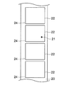
- FIG. 2 is a schematic view of a sheet on which irregularities are transferred by the embossing roll of FIG.
- the embossing roll 10 sandwiches the sheet 20 with another roller and narrows the pressure to transfer the unevenness of the transfer unit 16 and the shape of the symbol unit 18 to the sheet 20.
- the embossing roll 10 performs the transfer onto the long belt-like sheet 20 while rotating, the same transfer portion 16 and symbol portion 18 are transferred repeatedly every rotation.
- a sheet 20 shown in FIG. 2 is a sheet transferred by the embossing roll 10 of FIG.
- the embossing roll 10 shown in FIG. 1 has two transfer portions 16 (one is not shown because it exists behind the embossing roll 10 in FIG. 1), and two symbol portions 18 are formed.
- two transfer portions 16 one is not shown because it exists behind the embossing roll 10 in FIG. 1
- symbol portions 18 are formed.
- the sheet 20 of FIG. 2 to which 10 is transferred by two rotations four transferred portions 22 and four transferred symbol portions 24 are formed.
- the presence of the dust mark 21 makes the sheet 20 defective. Therefore, the dust adhering to the embossing roll 10 must be cleaned. Since the embossing roll 10 according to the present invention has the symbol portion 18, the transferred symbol portion 24 exists in the transferred sheet 20. Accordingly, the position of the dust 11 on the embossing roll 10 can be easily identified from the relative positional relationship between the dust mark 21 on the sheet 20 and the two transfer symbol portions 24.
- the garbage can be wiped off with a clean cloth, non-woven fabric, cotton swab, etc., and dust can be blown off by blowing air. Also, dust can be removed by adhering with an adhesive sheet or the like. Further, it can be washed with an organic solvent such as alcohol or acetone, water, water containing a surfactant, or the like.
- an organic solvent such as alcohol or acetone, water, water containing a surfactant, or the like.
- FIG. 3 is a schematic plan view of an embossing roll according to the second embodiment of the present invention.
- the difference from the embossing roll 10 according to the first embodiment shown in FIG. 1 is that, in the second embodiment, the symbol portion 18 is a numeral, and the transfer portion 16. Is that there are two rows in the longitudinal direction of the embossing roll 10.
- the symbol portion 18 is preferably arranged beside or near the transfer portion 16 for each group of the transfer portions 16 arranged in the longitudinal direction of the embossing roll 10. This is because it becomes easy to specify the position of the dust 11 existing on the surface of the embossing roll 10 from the transferred dust mark.
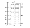
- FIG. 4 is a schematic view of a sheet on which irregularities are transferred by the embossing roll of FIG.
- the transfer unit 16 is arranged for each group of the transfer unit 16 aligned in the longitudinal direction of the embossing roll 10. Therefore, in the sheet 20 of FIG. 4 to which it has been transferred, a transfer symbol portion is placed beside the transferred portion 22 for each group of two transferred portions 22 arranged in a direction perpendicular to the longitudinal direction of the sheet 20. There are 24.
- the transfer symbol portion 24 is transferred as a different number (a shape in which the numbers 1 to 5 are inverted) for each group of the transferred portion 22.
- the position of the dust 11 is easily near “2” of the symbol portion 18 on the embossing roll 10.
- the exact position of the dust 11 on the embossing roll 10 can be identified very easily from the relationship between the relative position of the dust mark 21 on the sheet 20 and the transfer symbol portion 24 “2”.
- the dust 11 on the embossing roll 10 can be easily cleaned.
- the inverted number of the transfer symbol portion 24 transferred to the sheet 20 in FIG. Depending on the type of character, symbol, figure, etc., there are those that are likely to cause misreading when reversed, for example, the number “2” displayed in 7 segments and the number “5”.
- the characters, figures, symbols, etc. formed in the symbol portion 18 are those whose display does not change even if they are reversed, for example, alphabets “H”, “I”, “Y”, etc. It is desirable to use This is because, when the transfer symbol portion of the sheet 20 is read and the corresponding symbol portion of the embossing roll 10 is searched, misreading does not occur.
- the shape of the recognition object does not change by using plane-symmetric characters, figures, symbols, etc., so that the recognition becomes easy. It can also prevent misrecognition by computers.
- FIG. 5 is a schematic plan view of an embossing roll according to the third embodiment of the present invention.
- the difference from the embossing roll 10 according to the second embodiment shown in FIG. 3 is that, in the third embodiment, the symbol portions 18 are formed at both longitudinal ends of the cylindrical portion 14. It has been done.
- the symbol portion 18 formed at the left end portion of the cylindrical portion 14 is a numeral, and the symbol portion 18 formed at the right end portion is an alphabet, but is not limited thereto, and any symbol, Numbers, letters, graphics, etc. can be used, which is the same in all embodiments of the present invention.
- FIG. 6 is a schematic view of a sheet on which irregularities are transferred by the embossing roll of FIG.
- the embossing roll 10 according to the third embodiment has the symbol portions 18 formed at both ends in the longitudinal direction of the cylindrical portion 14. For this reason, in the sheet 20 transferred as shown in FIG. 6, transfer symbol portions 24 are formed on both sides of the transferred portion 22 with the transferred portion 22 interposed therebetween.
- FIG. 7 is a schematic plan view of an embossing roll in which a scale is formed between the symbol portions.
- a scale is formed between each alphabet of the symbol part 18 on the right side in the drawing.
- the scale is also transferred to the sheet. Therefore, on the sheet, even if the extension line is drawn between the symbols of the other transfer symbol part, a line is drawn from one transfer symbol part to the dust mark. Therefore, it is possible to specify the position of dust on the embossing roll 10 very quickly and accurately by examining the number of scales.
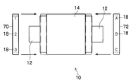
- FIG. 8 is a schematic plan view of an embossing roll according to the fourth embodiment of the present invention.
- the embossing roll 10 according to this embodiment is characterized in that the symbol drums 70 and 72, which are cylindrical portions on which the symbol portion 18 is formed, can be attached and detached.
- the position of the dust is specified by using the symbol drums 70 and 72 having the symbol part 18 matched to the number and position of the transfer parts existing in the cylindrical part 14 in accordance with the product to be manufactured. Becomes easier.
- FIG. 9 is a flowchart showing a dust cleaning method for the embossing roll.
- the sheet surface is photographed by a camera installed at a position where the sheet surface can be photographed to obtain an image (S1).
- An instruction for photographing to the camera is given by a computer.
- the acquired image data is transmitted from the camera to the computer.
- the computer recognizes the position of dust marks on the sheet surface from the received image data (S2).
- Various existing methods can be used to recognize the position of the dust mark. For example, reference image data that is image data of a sheet having no dust mark is stored in a recording unit in advance, and the reference image data is compared with data transmitted from the camera, so that there is a different portion in the transferred portion. Can be recognized as dust marks.
- the computer calculates the position of dust on the embossing roll from the position of dust marks on the sheet surface (S3).
- the calculation method the methods of the first to third embodiments described above can be used.
- the computer calculates the relative positional relationship between the transfer symbol portion 24 and the dust mark 21.
- the distance and direction from one or more types of transcription symbol portions 24 to the dust mark 21 are calculated, and the distance and direction are converted into the distance and direction on the surface of the embossing roll stored in advance. Is converted based on a conversion coefficient or a conversion function, and the position of dust is calculated based on the converted distance and direction from the symbol of the symbol portion 18 on the embossing roll.
- the computer selects two types of transcription symbol portions 24 close to the dust mark 21 and draws a straight line from each symbol to the dust mark 21.
- the symbol (or scale) of the transfer symbol part 24 that is on or close to the extension straight line is calculated, and the pair of symbols of the transfer symbol part 24 at both ends of each straight line is stored in the memory.
- the computer passes a straight line passing through the symbol pair of the symbol portion 18 corresponding to the symbol pair of the transcription symbol portion 24 stored in the memory, based on the data such as the dimension, shape, and symbol portion 18 arrangement of the embossing roll. And the intersection of these two straight lines or a range away from the intersection by a predetermined distance is specified as the dust 11 position.
- the computer can clearly show the dust position to the operator by irradiating the dust position on the embossing roll 10 with, for example, a spotlight or visible laser light. Yes (S4-1).
- the computer reads the rotation angle of the embossing roll from a rotary encoder installed on the shaft 12, controls the embossing roll 10 to rotate to a position where the spotlight can be irradiated to dust, and moves the optical axis of the spotlight.
- the spotlight can be irradiated to the position of the dust by controlling the driving means that can.
- the operator can easily know the position of the dust, so that the dust can be easily and quickly cleaned.
- the computer can display the dust position on an image display device such as a liquid crystal display device. This can be done by displaying a photographed image of the cylindrical portion 14 of the embossing roll 10 or an image of a schematic diagram on the image display device and displaying a dust position on the image (S4-2).
- an image display device such as a liquid crystal display device. This can be done by displaying a photographed image of the cylindrical portion 14 of the embossing roll 10 or an image of a schematic diagram on the image display device and displaying a dust position on the image (S4-2).
- the computer can remove dust by blowing clean air, for example, on the dust position on the embossing roll 10 based on the calculated dust position data on the embossing roll 10 (S4-3).
- step S4-1 This is different from the step S4-1 only in that the air is blown using air blowing means instead of the spotlight, and the other steps can be performed in the same manner.
- steps S4-1 to S4-3 may be executed alone or in any combination. That is, air may be blown while applying a spotlight. Thus, the operator can easily confirm whether or not the dust has been removed with air. Therefore, when the dust is not sufficiently cleaned, the operator can further easily clean the dust.
- the present invention is not limited to embossing rolls, but all rolls for narrowing a film or sheet, or all rolls that come into contact with the surface of the film or sheet while rotating, such as nip rolls and rotary presses. Any roll or any other roll can be used as long as it causes defects in the product due to the adhesion of dust.
Landscapes
- Engineering & Computer Science (AREA)
- Mechanical Engineering (AREA)
- Shaping Of Tube Ends By Bending Or Straightening (AREA)
- Cleaning In General (AREA)
- Feeding Of Articles By Means Other Than Belts Or Rollers (AREA)
Abstract
走行するシートの表面に回転しながら接触するロールであって、棒状の軸と、円筒形状の円筒部と、を備え、前記軸は、前記円筒部の長手方向両端面の中心を貫いて配置され、前記円筒部は、前記軸を回転中心として回転可能であり、前記シート上において製品としての機能を発揮しない部分に接触する前記円筒部表面に、前記シートに転写するための互いに異なる複数の文字、数字、図形、記号のいずれかの形状である記号形状が形成されているロール。
Description
本発明は、搬送されるシートに回転しながら接触するロール及びそのロールの清掃方法に関し、特にロール表面に形成された凹凸形状をシートに転写するエンボスロールと呼ばれるロール及びロール清掃方法に関する。
従来、レンチキュラー方式を使用することにより立体視が可能になるテレビ、ゲーム機、携帯電話、画像記録シート等の開発が行われてきた。レンチキュラー方式には、レンチキュラーレンズシートが使用される。レンチキュラーレンズシートとは、透明なシートの表面に凸レンズが無数に並んだレンズであるレンチキュラーレンズが形成されたシートである。
レンチキュラーレンズシートは、レンチキュラーレンズの形状を反転した凹凸形状が表面に形成されたエンボスロール(単にロールとも称する)を、透明なシートに押し当てて、凹凸形状をシートに転写することにより製造される。
このようなレンチキュラーレンズシートを製造する方法として、特許文献1には、レンズシートの製造方法が開示されている。特許文献1に開示されたレンズシートの製造方法は、透光性基材の一方の面に第1の円筒形型により第1の凹凸形状を形成したあと、第2の円筒形型により透光性基材の他方の面に第2の凹凸形状を形成するレンズシートの製造方法であって、少なくとも一方の円筒形型の端面近傍表面に円周方向のほぼ全周に渡って凸状リブが形成されている円筒形型を用いることを備えている。
これにより、透光性基材の蛇行を抑止し、出射面側および入射面側に形成されるレンズパターンの凹凸形状の軸ズレを抑制することが出来るとしている。
また、レンチキュラーレンズシートを製造する方法として、特許文献2には、フィルムスクリーンの製造装置及び製造方法が開示されている。特許文献2に開示されたフィルムスクリーンの製造装置は、第1の成形ロール及び/または第2の成形ロールの一端または両端に、ベースフィルムの横移動及び/または熱挙動を防止する位置ズレ防止手段を備えている。
これにより、ベースフィルムの熱挙動の影響を少なくでき、簡単に必要精度の位置合わせを行うことができるとしている。
しかしながら、従来のロールを使用してレンチキュラーレンズシートを製造する場合において、ロールの表面にゴミが付着していた場合、そのゴミを清掃によって取り除くことについて、以下の課題があった。
第1の課題としては、これらのロールは、例えば長手方向の長さが2mほどもあり、重量も700kgほどもあるので、ロールを装置から取り外してロール全体を清掃、洗浄するのは、手間も工数も必要であり、困難であった。
第2の課題としては、第1の課題により、ロールを取り外すことなく、ゴミの付いた部分のみを清掃することが必要であるが、ロールの表面には、微細な凹凸(数十から数百μmのサイズ)が形成されているので、ロール表面を布等で払拭すると、凹凸を損傷させる可能性があった。そのため、ゴミを綿棒等で一つずつ取り除く必要があるが、以下の理由によりゴミの位置の特定が困難であるためゴミの清掃が困難であった。
即ち、ゴミの位置の特定が困難である理由とは、ロールは非常に大きいものであり(例えば長さ2m、重量700kg)、かつ、広い面積のロール表面には、無数の凹凸が形成されているために、その無数の凹凸の中に隠れたゴミの位置を特定することは、極めて困難であった。
ここで、特許文献1、特許文献2には、ロールの端面近傍であって、レンチキュラーレンズの反転形状が形成されていない部分に一つまたは複数の同じ立体図形形状を形成したロールが開示されている。
言い換えると、特許文献1、特許文献2には、ロールがシートと接触したときにシート上において製品としての機能を発揮しない部分(レンチキュラーレンズが形成されない部分)に接触するロールの表面部分に、ロールの回転方向に並んだ同一の立体図形形状が形成されたロール、及び、ロールの回転方向に凸状リブ形状が連続的に形成されたロールが開示されている。
しかしながら、上記特許文献1に開示されたロールは、その端面近傍に形成された立体図形形状が、ロールの回転方向に連続的に形成された一つの形状であるため、その立体図形形状の位置を基準として、ロール表面に付着したゴミの位置を相対的に特定することが出来なかった。
また、上記特許文献2に開示されたロールは、その端面近傍に形成された立体図形形状が、ロールの回転方向に形成された複数の同じ立体図形形状であるために、その立体図形形状の位置を基準として、ロール表面に付着したゴミの位置を相対的に特定することが出来なかった。
更に説明すると、シートに転写されたゴミ痕と、シートに転写された前記立体図形形状との相対的位置関係に基づいて、ロール表面において、ゴミの位置を特定することが不可能であった。
本発明はこのような事情に鑑みてなされたもので、ロールを取り外すことなく、ロール上に付着したゴミの位置を容易に特定して清掃することが出来るロール及びロール清掃方法を提供することにある。
上記課題は、以下の発明により解決することが出来る。即ち本発明のロールは、走行するシートの表面に回転しながら接触するロールであって、棒状の軸と、円筒形状の円筒部と、を備え、前記軸は、前記円筒部の長手方向両端面の中心を貫いて配置され、前記円筒部は、前記軸を回転中心として回転可能であり、前記シート上において製品としての機能を発揮しない部分に接触する前記円筒部表面に、前記シートに転写するための互いに異なる複数の文字、数字、図形、記号のいずれかの形状である記号形状が形成されていることを主要な特徴にしている。
これにより、ロール上に付着したゴミの位置は、シートに転写されたゴミの痕と、シートに転写された記号形状との相対的な位置関係から、容易に特定することが出来るので、ゴミの清掃が容易になる。
ここで、シート上において製品としての機能を発揮しない部分とは、製品としてのシートの機能を発揮しない部分のことである。例えば、ロールがエンボスロールであり、シートがレンチキュラーレンズシートの場合は、シート上においてレンチキュラーレンズが形成されていない部分のことである。よって、前記シート上において製品としての機能を発揮しない部分に接触する前記円筒部表面とは、エンボスロールの場合は、シートに転写するための凹凸が形成されていない部分であって、シートに接触する部分のことである。
更に、ロールが輪転機のロールの場合は、同様に考えて、シート上において製品としての機能を発揮しない部分とは、シート上において何も印刷されていない部分であり、前記シート上において製品としての機能を発揮しない部分に接触する前記円筒部表面とは、シート上において何も印刷されていない部分に接触する円筒部表面部分のことである。
更にまた、ロールがニップロールなどの場合は、シート上において製品としての機能を発揮しない部分とは、そのシートが製品化されたときに、その部分に記号形状を転写しても製品に影響を及ぼさない部分であり、前記シート上において製品としての機能を発揮しない部分に接触する前記円筒部表面とは、シート上の製品に影響を及ぼさない部分に接触する円筒部表面部分のことである。
また、本発明は、シートの表面に回転しながら接触するロールならばどのようなロールにも適用することが出来る。例えば、輪転機のロール、シートを狭圧するためのニップロール、シートに凹凸形状を転写するためのエンボスロールなどである。この中では、エンボスロールに適用するのが、一番効果が高い。その理由は、エンボスロールは、巨大なので取り外して全体を洗浄することが困難であり、微小な凹凸形状が表面に形成されているので、全体を払拭することが出来ず、ゴミの位置を特定してゴミを取り除かなければならないからである。
また、本発明のロールは、前記ロールが、前記シートに転写するための複数の凹凸を備えたエンボスロールであることを主要な特徴にしている。上述したように、エンボスロールに適用することによって、エンボスロール特有のゴミ清掃の課題を解決できる。
更に、本発明のロールは、複数の前記記号形状が、前記円筒部の回転方向に並んで形成されており、複数の前記記号形状の間に目盛り線が形成されていることを主要な特徴にしている。
これにより、シートに転写された目盛り線と、ゴミ痕との相対位置を考慮することにより、ロール上でのゴミの位置を更に精度良く、容易に特定することができる。
これにより、シートに転写された目盛り線と、ゴミ痕との相対位置を考慮することにより、ロール上でのゴミの位置を更に精度良く、容易に特定することができる。
更にまた、本発明のロールは、前記記号形状が、前記円筒部の長手方向両端部のそれぞれに複数形成されていることを主要な特徴にしている。
これにより、シートに転写された2つの記号形状からゴミ痕に直線を引き、その直線と交わる、または、近接するシートの反対端部に転写された記号形状を記憶し、ロール上において、対応する記号形状同士で直線を引くことにより、その交点または交点付近にゴミを発見することが出来る。
また、本発明のロールは、複数の前記記号形状が、前記円筒部の長手方向端部に位置する脱着部に、前記円筒部の回転方向に並んで形成されており、前記脱着部は、前記円筒部と脱着自在に構成されていることを主要な特徴にしている。
これにより、ロール全てに記号形状を形成する必要がない。また、そのロールにあった記号形状を選択することができ、さらには、ゴミの発生具合等に応じて、記号形状の密度、大きさ等を選択して使用することができる。
更に、本発明のロール清掃方法は、上記記載のロールに付着したゴミを清掃するロール清掃方法であって、コンピュータの指示によりカメラが、前記ロールに接触したシートの表面を撮影して画像を取得するステップと、カメラが、前記画像のデータである画像データをコンピュータに送信するステップと、コンピュータが、前記画像データに基づいて、前記ロールによって前記シート表面に転写された記号形状である転写形状の位置に対する、前記ロールに付着したゴミによって前記シート表面に転写されたゴミ痕の相対的位置を算出するステップと、コンピュータが、前記相対的位置に基づいて、前記ロール上の記号形状の位置から、前記ロール上でのゴミの位置を算出するステップと、コンピュータが、前記ゴミの位置に基づいて、前記ロールの回転を駆動する手段を制御して、ゴミを除去またはゴミの位置を作業者に明示するためのゴミ除去補助手段に前記ゴミが近付く位置まで回転させるステップと、コンピュータが、前記ゴミの位置に基づいて、前記ゴミ除去補助手段の向きが前記ゴミに向くように、前記ゴミ除去補助手段の向きを制御するゴミ除去補助手段制御装置を制御して、前記ゴミ除去手段を作動させるステップと、を備えることを主要な特徴にしている。
これにより、容易にロール上のゴミを取り除くことが出来る。
本発明によれば、付着したゴミ位置を発見することが容易なロール、及びロールに付着したゴミを容易に除去できるロール清掃方法を提供することが出来る。
本発明によれば、量産性に優れ、高品質の印画用シートを得ることができる。
以下添付図面に従って本発明の好ましい実施の形態について説明する。本発明は以下の好ましい実施の形態により説明されるが、本発明の範囲を逸脱すること無く、多くの手法により変更を行うことができ、本実施の形態以外の他の実施の形態を利用することができる。従って、本発明の範囲内における全ての変更が請求の範囲に含まれる。また、本明細書において「~」を用いて表される数値範囲は、「~」の前後に記載される数値を含む範囲を意味する。
(1)第1の実施形態
<エンボスロールの構成>
本発明の第1の実施形態に係るエンボスロール(単にロールと称する場合もある)について図面を参照して説明する。図1は、第1の実施形態に係るエンボスロールの概略平面図である。エンボスロール10は、棒状の軸12と、円柱形状の円筒部14とを主に備えて構成される。
<エンボスロールの構成>
本発明の第1の実施形態に係るエンボスロール(単にロールと称する場合もある)について図面を参照して説明する。図1は、第1の実施形態に係るエンボスロールの概略平面図である。エンボスロール10は、棒状の軸12と、円柱形状の円筒部14とを主に備えて構成される。
軸12は、円筒部14の長手方向両端面の中心を貫いて配置される。言い換えると、軸12は、円筒部14の回転軸、即ち中心軸になるように配置される。
円筒部14は、その表面のうち曲面部分に、転写部16と記号部18とを有している。
転写部16とは、製品となるシートに転写するための複数の凹凸が形成された部分である。製造すべき製品がレンチキュラーレンズシートの場合は、形成すべきレンチキュラーレンズ形状とは凹凸が反転された形状がこの転写部16に形成されている。この転写部16は、円筒部14において製品のサイズに対応した大きさの範囲を占めており、円筒部14に1つまたは複数形成されている。
記号部18とは、文字、数字、図形、記号等が凹凸で形成された部分であり、1つまたは複数存在する。図1においては、記号部18は、2種類の記号(「+」と「-」)で表されている。記号部18は、複数存在するときは、それぞれが異なった記号等であることが好ましい。また、同一の記号等である場合は、円周方向において同一間隔で存在しない方が好ましい。
記号部18は、円筒部14の曲面部分のうち転写部16以外の部分に形成されている。これにより、記号部18がシートに転写されたとき、シート上で製品になる部分以外(転写部によって凹凸が転写される部分以外)に、転写されることになる。即ち、記号部18は、シート上において製品としての機能を発揮しない部分、または、製品にならない部分に対応する円筒部14上の部分に配置される。
<エンボスロールの作動>
次に本発明の第1の実施形態に係るエンボスロールの作動について、図2を参照して説明する。図2は、図1のエンボスロールにより凹凸が転写されたシートの概略図である。エンボスロール10は、シート20を別のローラとの間に挟んで狭圧し、転写部16の凹凸と、記号部18の形状とをシート20に転写する。この際、エンボスロール10は、回転しながら帯状の長いシート20に転写を行うため、1回転ごとに繰り返して同じ転写部16、記号部18を転写することになる。
次に本発明の第1の実施形態に係るエンボスロールの作動について、図2を参照して説明する。図2は、図1のエンボスロールにより凹凸が転写されたシートの概略図である。エンボスロール10は、シート20を別のローラとの間に挟んで狭圧し、転写部16の凹凸と、記号部18の形状とをシート20に転写する。この際、エンボスロール10は、回転しながら帯状の長いシート20に転写を行うため、1回転ごとに繰り返して同じ転写部16、記号部18を転写することになる。
シート20において、転写部16の凹凸が転写された部分を被転写部22で表し、記号部18の形状が転写された部分を転写記号部24で表す。図2で示すシート20は、図1のエンボスロール10が2回転して転写したシートである。
図1のエンボスロール10には、転写部16が2つ(1つは図1においてエンボスロール10の後ろ側に存在するため不図示)、記号部18が2つ形成されているので、エンボスロール10が2回転して転写された図2のシート20においては、被転写部22が4つ、転写記号部24が4つ形成されている。
ここで、図1に示すように、図1のエンボスロール10には、ゴミ11が付着している。このゴミ11の形状が転写されたのが図2のゴミ痕21である。エンボスロール10が2回転しているので、ゴミ痕21は、2つ形成されている。
ゴミ痕21が存在することにより、シート20は不良品になる。そのため、エンボスロール10に付着しているゴミを清掃しなければならない。本発明に係るエンボスロール10は、記号部18を有しているため、転写したシート20には、転写記号部24が存在している。これにより、シート20のゴミ痕21と、2つの転写記号部24との相対位置関係から、容易にエンボスロール10上のゴミ11の位置を特定することができる。
よって、エンボスロール10上のゴミを容易に発見し、清掃することが可能になる。ゴミの清掃は、様々手段を用いることができる。例えば、清潔な布、不織布、綿棒等で拭き取ることもでき、エアーを吹き付けてゴミを吹き飛ばすこともできる。また、粘着シート等でゴミを接着して取り除くこともできる。更に、アルコール、アセトン等の有機溶剤、水、界面活性剤入りの水等で洗浄することもできる。
(2)第2の実施形態
<エンボスロールの構成>
次に本発明の第2の実施形態に係るエンボスロールの構成について説明するが、第1の実施形態と異なる部分について説明し、同じ部分については説明を省略する。
<エンボスロールの構成>
次に本発明の第2の実施形態に係るエンボスロールの構成について説明するが、第1の実施形態と異なる部分について説明し、同じ部分については説明を省略する。
図3は、本発明の第2の実施形態に係るエンボスロールの概略平面図である。図3を参照して、図1に示される第1の実施形態に係るエンボスロール10との相違は、第2の実施形態においては、記号部18が、数字であること、及び、転写部16がエンボスロール10の長手方向に2列存在することである。
図3においては、背面に隠れるため全ては図示されていないが、記号部18は、1から5まで存在し、転写部16は、エンボスロール10の回転方向に5つ、長手方向に2つ、合計10存在している。
記号部18は、エンボスロール10の長手方向に並んだ転写部16のひとまとまりごとに当該転写部16の横、または、近辺に配置されることが好ましい。これにより、転写されたゴミ痕からエンボスロール10表面に存在するゴミ11の位置を特定することが容易になるからである。
<エンボスロールの作動>
次に本発明の第2の実施形態に係るエンボスロールの作動について図4を参照して説明するが、第1の実施形態と異なる部分について説明し、同じ部分については説明を省略する。図4は、図3のエンボスロールにより凹凸が転写されたシートの概略図である。
次に本発明の第2の実施形態に係るエンボスロールの作動について図4を参照して説明するが、第1の実施形態と異なる部分について説明し、同じ部分については説明を省略する。図4は、図3のエンボスロールにより凹凸が転写されたシートの概略図である。
第1の実施形態との相違部分について説明する。エンボスロール10において、転写部16は、エンボスロール10の長手方向に並んだ転写部16のひとまとまりごとに配置されている。そのため、それが転写された図4のシート20においては、シート20の長手方向に垂直な方向に2つ並んだ被転写部22のひとまとまりごとに、当該被転写部22の横に転写記号部24が存在する。
さらに、転写記号部24は、被転写部22のひとまとまりごとに、異なった数字(数字1~5が反転した形状)として転写されている。これにより、例えば、ゴミ痕21が数字「2」の転写記号部24付近に存在していた場合、ゴミ11の位置は、エンボスロール10上では、記号部18の「2」付近であると容易に分かる。更に、シート20のゴミ痕21と転写記号部24「2」との相対位置との関係から、極めて容易にエンボスロール10上でのゴミ11の正確な位置を特定することができる。
このため、エンボスロール10上のゴミ11の洗浄を容易に行うことができる。なお、図4のシート20に転写された転写記号部24の反転した数字を見れば分かるように、反転すると分かりにくい。文字、記号、図形の等の種類によっては、その字体によっては反転すると誤読を生じやすいもの、例えば、7セグメント表示された数字の「2」と数字の「5」など、が存在する。
よって、記号部18に形成される文字、図形、記号等は、反転しても表示が変わらないもの、例えば、アルファベットの「H」、「I」、「Y」等、即ち、面対称なものを使用することが望ましい。これにより、シート20の転写記号部を読み取り、エンボスロール10の対応する記号部を探すときに、誤読を生じることがないからである。
また、コンピュータによって記号部、転写記号部の画像を読み込ませて認識させる際も、面対称の文字、図形、記号等をすることにより、認識対象物の形が変化しないので、認識が容易になり、コンピュータによる誤認識を防ぐこともできる。
(3)第3の実施形態
<エンボスロールの構成>
次に本発明の第3の実施形態に係るエンボスロールの構成について説明するが、第2の実施形態と異なる部分について説明し、同じ部分については説明を省略する。
<エンボスロールの構成>
次に本発明の第3の実施形態に係るエンボスロールの構成について説明するが、第2の実施形態と異なる部分について説明し、同じ部分については説明を省略する。
図5は、本発明の第3の実施形態に係るエンボスロールの概略平面図である。図5を参照して、図3に示される第2の実施形態に係るエンボスロール10との相違は、第3の実施形態においては、記号部18が、円筒部14の長手方向両端部に形成されていることである。
図5において、円筒部14の左端部に形成された記号部18は数字であり、右端部に形成された記号部18はアルファベットであるが、これに限定されるものではなく、任意の記号、数字、文字、図形等を使用することができ、それは、本発明における全ての実施形態において同様である。
<エンボスロールの作動>
次に本発明の第3の実施形態に係るエンボスロールの作動について図6を参照して説明するが、第2の実施形態と異なる部分について説明し、同じ部分については説明を省略する。図6は、図5のエンボスロールにより凹凸が転写されたシートの概略図である。
次に本発明の第3の実施形態に係るエンボスロールの作動について図6を参照して説明するが、第2の実施形態と異なる部分について説明し、同じ部分については説明を省略する。図6は、図5のエンボスロールにより凹凸が転写されたシートの概略図である。
第2の実施形態との相違部分について説明する。第3の実施形態に係るエンボスロール10は、図5に示されるように、記号部18が、円筒部14の長手方向両端部に形成されている。このため、図6に示すように転写されたシート20では、被転写部22を挟んで被転写部22の両側に転写記号部24が形成されている。
これにより、ゴミ痕21がシート20に存在したとき、ゴミ痕21に近い2つの転写記号部24からゴミに向けて直線を引きその延長線上に存在する、または、その延長線に近い反対側の転写記号部24の記号を調べることによって、極めて容易に且つ正確にエンボスロール10上のゴミ位置を特定することができる。
例えば、図6においては、転写記号部24のうち「反転した3」とゴミ痕21とを直線60でむすぶと、その延長線が転写記号部24の「反転したC」に近接する。また、転写記号部24のうち「反転した2」とゴミ痕21とを直線62でむすぶと、その延長線が転写記号部24の「反転したE」に近接する。
よって、図5のエンボスロール10において、記号部18の「2」と記号部18の「E」とを直線52でむすび、記号部18の「3」と記号部18の「C」とを直線50でむすび、直線50と直線52の交点にゴミ11が存在することが分かる。
ここで、円筒部14の長手方向両端に形成された記号部18の一方または両方において、円筒部の回転方向の各記号部18の間に目盛り状のマーク等を形成しても良い。これについて、図7を参照して説明する。図7は、記号部間に目盛りを形成したエンボスロールの概略平面図である。
図7に示すように、図上において右側の記号部18の各アルファベットの間には、目盛りが形成されている。これにより、目盛りもシートに転写されるので、シートにおいて、片方の転写記号部からゴミ痕に直線をむすびその延長線がもう一方の転写記号部の記号と記号の間に引かれても、目盛りが形成されているので、何個目の目盛りかを調べることにより、エンボスロール10上のゴミの位置を極めて速く正確に特定することが可能になる。
(4)第4の実施形態
次に本発明の第4の実施形態に係るエンボスロールの構成について説明するが、第3の実施形態と異なる部分について説明し、同じ部分については説明を省略する。
次に本発明の第4の実施形態に係るエンボスロールの構成について説明するが、第3の実施形態と異なる部分について説明し、同じ部分については説明を省略する。
図8は、本発明の第4の実施形態に係るエンボスロールの概略平面図である。図8を参照すると、本実施形態のエンボスロール10の特徴は、記号部18が形成された円筒部分である記号ドラム70、72が脱着可能になっていることである。
これにより、製造する製品に合わせて、例えば、円筒部14に存在する転写部の数、位置に合わせた記号部18を有する記号ドラム70、72を使用することにより、ゴミの位置を特定することが容易になる。
(5)エンボスロールのゴミ清掃方法
次に、エンボスロールのゴミ清掃方法について図面を参照して説明する。図9は、エンボスロールのゴミ清掃方法を示すフロー図である。図9を参照して、シート表面を撮影できる位置に設置されたカメラにより、シート表面を撮影して画像を取得する(S1)。カメラに対する撮影の指示はコンピュータによって行われる。取得した画像データは、カメラからコンピュータに送信される。
次に、エンボスロールのゴミ清掃方法について図面を参照して説明する。図9は、エンボスロールのゴミ清掃方法を示すフロー図である。図9を参照して、シート表面を撮影できる位置に設置されたカメラにより、シート表面を撮影して画像を取得する(S1)。カメラに対する撮影の指示はコンピュータによって行われる。取得した画像データは、カメラからコンピュータに送信される。
コンピュータは、受信した画像データからシート表面のゴミ痕の位置を認識する(S2)。ゴミ痕の位置の認識は、様々な既存の方法を用いることができる。例えば、予め、ゴミ痕がないシートの画像データである参照画像データを記録手段に保管しておき、この参照画像データとカメラから送信されたデータを比較して、被転写部に異なる部分が存在したときに、ゴミ痕と認識することができる。
次に、コンピュータは、シート表面のゴミ痕位置からエンボスロール上のゴミの位置を算出する(S3)。算出方法は、上述した、実施例1~3の方法を用いることができる。実施例1、2の方法を用いる場合は(図1、図2参照)、コンピュータは、転写記号部24とゴミ痕21との相対的位置関係を算出する。
即ち、1種類以上の転写記号部24の記号からゴミ痕21までの距離と方向とを算出し、その距離と方向とを、予め保存されているエンボスロールの表面での距離と方向とに換算するための換算係数または、換算関数に基づいて換算し、エンボスロール上の記号部18の記号からその換算した距離と方向とに基づいてゴミの位置を算出する。
実施例3の方法では(図5、図6、図7参照)、コンピュータは、ゴミ痕21に近い2種類の転写記号部24の記号を選択し、それぞれの記号からゴミ痕21まで直線を引きその直線の延長直線上にある、または、延長直線に近い転写記号部24の記号(または目盛り)を算出し、それぞれの直線の両端にある転写記号部24の記号のペアをメモリに記憶する。
次に、コンピュータは、エンボスロールの寸法、形状、記号部18配置等のデータに基づいて、メモリに記憶された転写記号部24の記号のペアに対応する記号部18の記号のペアを通る直線を計算し、それらの2つの直線の交点、または、その交点から予め定められた距離離れた範囲をゴミ11位置として特定する。
算出されたエンボスロール10上のゴミ位置のデータに基づいて、コンピュータは、エンボスロール10上のゴミ位置に例えばスポットライト、可視レーザ光を照射することにより、ゴミ位置を作業者に明示することが出来る(S4-1)。
例えば、コンピュータは、軸12に設置されたロータリエンコーダからエンボスロールの回転角度を読み込み、スポットライトをゴミに照射できる位置までエンボスロール10が回転するように制御し、スポットライトの光軸を移動させることができる駆動手段を制御して、ゴミの位置にスポットライトを照射することができる。これにより、作業者は、容易にゴミの位置を知ることができるので、ゴミの清掃を容易に、かつ、迅速に行うことが出来る。
また、コンピュータは、液晶表示装置等の画像表示装置にゴミ位置を表示させることができる。これは、画像表示装置にエンボスロール10の円筒部14の撮影画像、または、概略図の画像を表示させ、その画像上にゴミ位置を表示することで行うことが出来る(S4-2)。
更に、コンピュータは、算出されたエンボスロール10上のゴミ位置のデータに基づいて、エンボスロール10上のゴミ位置に例えば清浄なエアーを吹き付けることにより、ゴミを取り除くことが出来る(S4-3)。
これは、上記ステップS4-1において、スポットライトの代わりエアー吹きつけ手段を用いてエアーを吹き付けるところのみが異なり、それ以外は同様に行うことが出来る。
また、上述のステップS4-1~S4-3は、単独でも、任意の組み合わせでも、全てが実行されても良い。即ち、スポットライトを当てつつ、エアーを吹き付けても良い。これにより、エアーでゴミが取り除かれたか否かを作業者が容易に確認することが出来るので、ゴミの清掃が十分でないときは、作業者が更にゴミの清掃を行うことが容易になる。
ここで、本発明は、エンボスロールに限定されるものではなく、フィルムやシートを狭圧する全てのロール、または、フィルムやシートの表面に回転しながら接する全てのロール、例えば、ニップロール、輪転機のロール、その他どのようなロールでも、ゴミの付着で製品に不具合が発生するものならば適用することが出来る。
10…エンボスロール、11…ゴミ、12…軸、14…円筒部、16…転写部、18…記号部、20…シート、21…ゴミ痕、22…被転写部、24…転写記号部、50…直線、52…直線、60…直線、62…直線、70…記号ドラム
Claims (6)
- 走行するシートの表面に回転しながら接触するロールであって、
棒状の軸と、
円筒形状の円筒部と、
を備え、
前記軸は、前記円筒部の長手方向両端面の中心を貫いて配置され、
前記円筒部は、前記軸を回転中心として回転可能であり、
前記シート上において製品としての機能を発揮しない部分に接触する前記円筒部表面に、前記シートに転写するための互いに異なる複数の文字、数字、図形、記号のいずれかの形状である記号形状が形成されているロール。 - 前記ロールが、前記シートに転写するための複数の凹凸を備えたエンボスロールである請求項1に記載のロール。
- 複数の前記記号形状が、前記円筒部の回転方向に並んで形成されており、
複数の前記記号形状の間に目盛り線が形成されている請求項1または2に記載のロール。 - 前記記号形状が、前記円筒部の長手方向両端部のそれぞれに複数形成されている請求項1から3のいずれか一つに記載のロール。
- 複数の前記記号形状が、前記円筒部の長手方向端部に位置する脱着部に、前記円筒部の回転方向に並んで形成されており、
前記脱着部は、前記円筒部と脱着自在に構成されている請求項1から4のいずれか一つに記載のロール。 - 請求項1から5のいずれか一つに記載のロールに付着したゴミを清掃するロール清掃方法であって、
コンピュータの指示によりカメラが、前記ロールに接触したシートの表面を撮影して画像を取得するステップと、
カメラが、前記画像のデータである画像データをコンピュータに送信するステップと、
コンピュータが、前記画像データに基づいて、前記ロールによって前記シート表面に転写された記号形状である転写形状の位置に対する、前記ロールに付着したゴミによって前記シート表面に転写されたゴミ痕の相対的位置を算出するステップと、
コンピュータが、前記相対的位置に基づいて、前記ロール上の記号形状の位置から、前記ロール上でのゴミの位置を算出するステップと、
コンピュータが、前記ゴミの位置に基づいて、前記ロールの回転を駆動する手段を制御して、ゴミを除去またはゴミの位置を作業者に明示するためのゴミ除去補助手段に前記ゴミが近付く位置まで回転させるステップと、
コンピュータが、前記ゴミの位置に基づいて、前記ゴミ除去補助手段の向きが前記ゴミに向くように、前記ゴミ除去補助手段の向きを制御するゴミ除去補助手段制御装置を制御して、前記ゴミ除去手段を作動させるステップと、
を備えるロール清掃方法。
Applications Claiming Priority (2)
| Application Number | Priority Date | Filing Date | Title |
|---|---|---|---|
| JP2011073118A JP2012206012A (ja) | 2011-03-29 | 2011-03-29 | ロール及びロール清掃方法 |
| JP2011-073118 | 2011-03-29 |
Publications (1)
| Publication Number | Publication Date |
|---|---|
| WO2012132896A1 true WO2012132896A1 (ja) | 2012-10-04 |
Family
ID=46930634
Family Applications (1)
| Application Number | Title | Priority Date | Filing Date |
|---|---|---|---|
| PCT/JP2012/056523 Ceased WO2012132896A1 (ja) | 2011-03-29 | 2012-03-14 | ロール及びロール清掃方法 |
Country Status (3)
| Country | Link |
|---|---|
| JP (1) | JP2012206012A (ja) |
| TW (1) | TW201244840A (ja) |
| WO (1) | WO2012132896A1 (ja) |
Cited By (3)
| Publication number | Priority date | Publication date | Assignee | Title |
|---|---|---|---|---|
| JP2012218294A (ja) * | 2011-04-08 | 2012-11-12 | Hitachi Industrial Equipment Systems Co Ltd | パターン転写装置及びパターン転写方法 |
| CN104438223A (zh) * | 2014-12-01 | 2015-03-25 | 广西大学 | 电脑除尘器 |
| CN108555482A (zh) * | 2018-04-08 | 2018-09-21 | 北京点域科技有限公司 | 一种焊接机床用焊渣清理装置及其使用方法 |
Citations (2)
| Publication number | Priority date | Publication date | Assignee | Title |
|---|---|---|---|---|
| JPH04364911A (ja) * | 1991-06-13 | 1992-12-17 | Canon Inc | 光記録媒体用樹脂基板シートの製造方法および製造装置 |
| JP2009233956A (ja) * | 2008-03-26 | 2009-10-15 | Dainippon Printing Co Ltd | エンボス装置、エンボスロール、凹凸パターン、加工品、および、加工品の製造方法 |
-
2011
- 2011-03-29 JP JP2011073118A patent/JP2012206012A/ja not_active Withdrawn
-
2012
- 2012-03-14 WO PCT/JP2012/056523 patent/WO2012132896A1/ja not_active Ceased
- 2012-03-23 TW TW101109991A patent/TW201244840A/zh unknown
Patent Citations (2)
| Publication number | Priority date | Publication date | Assignee | Title |
|---|---|---|---|---|
| JPH04364911A (ja) * | 1991-06-13 | 1992-12-17 | Canon Inc | 光記録媒体用樹脂基板シートの製造方法および製造装置 |
| JP2009233956A (ja) * | 2008-03-26 | 2009-10-15 | Dainippon Printing Co Ltd | エンボス装置、エンボスロール、凹凸パターン、加工品、および、加工品の製造方法 |
Cited By (3)
| Publication number | Priority date | Publication date | Assignee | Title |
|---|---|---|---|---|
| JP2012218294A (ja) * | 2011-04-08 | 2012-11-12 | Hitachi Industrial Equipment Systems Co Ltd | パターン転写装置及びパターン転写方法 |
| CN104438223A (zh) * | 2014-12-01 | 2015-03-25 | 广西大学 | 电脑除尘器 |
| CN108555482A (zh) * | 2018-04-08 | 2018-09-21 | 北京点域科技有限公司 | 一种焊接机床用焊渣清理装置及其使用方法 |
Also Published As
| Publication number | Publication date |
|---|---|
| JP2012206012A (ja) | 2012-10-25 |
| TW201244840A (en) | 2012-11-16 |
Similar Documents
| Publication | Publication Date | Title |
|---|---|---|
| WO2012132896A1 (ja) | ロール及びロール清掃方法 | |
| JP5869250B2 (ja) | 印刷装置、印刷方法及びその印刷方法を実行させるためのプログラムを記録したコンピュータ読み取り可能な記録媒体 | |
| TW201820671A (zh) | 基板處理裝置及基板處理方法 | |
| CN109562618A (zh) | 套准误差检测装置、套准误差检测方法以及印刷品 | |
| JP2009276522A (ja) | 画像記録装置 | |
| JP2009527797A (ja) | マスクと印刷版の接合 | |
| JP5925609B2 (ja) | シート状製品の検査システム及びシート状製品の検査方法 | |
| JP2001058446A (ja) | インクジェットプリントシステムにおける印刷検証装置 | |
| ES2790742T3 (es) | Dispositivo y método para limpiar una cuchilla tangente en una unidad de impresión de una máquina de impresión de huecograbado | |
| US20150177667A1 (en) | Raised support image corresponding to type of media to support media | |
| CN104228335A (zh) | 清洗装置、清洗方法和印刷系统 | |
| JP2009080131A (ja) | シート状製品の検査方法及びシート状製品の検査システム及びシート状製品及び枚葉物 | |
| JP2016120658A (ja) | 印刷装置、および、印刷方法 | |
| JP2018200478A (ja) | 記録材判別装置及びそれを備えた画像形成装置 | |
| CN103342047B (zh) | 一种轮辐式防蹭脏滚筒 | |
| JP2569379Y2 (ja) | 円柱体のひずみ測定装置 | |
| JP2012032384A (ja) | 印刷検査装置、印刷検査方法、および当該印刷検査方法で所定パターンを印刷するために用いる版 | |
| JP2018043814A (ja) | 記録材供給回収装置及びこれを用いた画像形成装置 | |
| JP2014016217A (ja) | 欠陥マーキング方法、光学フィルムの製造方法および欠陥マーキング装置 | |
| WO2015016222A1 (ja) | 搬送装置 | |
| JP6393763B2 (ja) | 型 | |
| CN102001236A (zh) | 一种胶囊激光标记装置 | |
| CN203561830U (zh) | 成像装置 | |
| JP2013186177A (ja) | 賦型用金型の製造方法及び賦型用金型の製造装置 | |
| CN108917570B (zh) | 一种检测探头、套合精度检测装置及其检测方法 |
Legal Events
| Date | Code | Title | Description |
|---|---|---|---|
| 121 | Ep: the epo has been informed by wipo that ep was designated in this application |
Ref document number: 12765399 Country of ref document: EP Kind code of ref document: A1 |
|
| NENP | Non-entry into the national phase |
Ref country code: DE |
|
| 122 | Ep: pct application non-entry in european phase |
Ref document number: 12765399 Country of ref document: EP Kind code of ref document: A1 |