WO2012132857A1 - 圧延銅箔 - Google Patents
圧延銅箔 Download PDFInfo
- Publication number
- WO2012132857A1 WO2012132857A1 PCT/JP2012/056270 JP2012056270W WO2012132857A1 WO 2012132857 A1 WO2012132857 A1 WO 2012132857A1 JP 2012056270 W JP2012056270 W JP 2012056270W WO 2012132857 A1 WO2012132857 A1 WO 2012132857A1
- Authority
- WO
- WIPO (PCT)
- Prior art keywords
- copper foil
- rolling
- rolled
- thickness
- final
- Prior art date
- Legal status (The legal status is an assumption and is not a legal conclusion. Google has not performed a legal analysis and makes no representation as to the accuracy of the status listed.)
- Ceased
Links
Images






Classifications
-
- B—PERFORMING OPERATIONS; TRANSPORTING
- B21—MECHANICAL METAL-WORKING WITHOUT ESSENTIALLY REMOVING MATERIAL; PUNCHING METAL
- B21B—ROLLING OF METAL
- B21B3/00—Rolling materials of special alloys so far as the composition of the alloy requires or permits special rolling methods or sequences ; Rolling of aluminium, copper, zinc or other non-ferrous metals
-
- C—CHEMISTRY; METALLURGY
- C22—METALLURGY; FERROUS OR NON-FERROUS ALLOYS; TREATMENT OF ALLOYS OR NON-FERROUS METALS
- C22F—CHANGING THE PHYSICAL STRUCTURE OF NON-FERROUS METALS AND NON-FERROUS ALLOYS
- C22F1/00—Changing the physical structure of non-ferrous metals or alloys by heat treatment or by hot or cold working
- C22F1/08—Changing the physical structure of non-ferrous metals or alloys by heat treatment or by hot or cold working of copper or alloys based thereon
-
- B—PERFORMING OPERATIONS; TRANSPORTING
- B21—MECHANICAL METAL-WORKING WITHOUT ESSENTIALLY REMOVING MATERIAL; PUNCHING METAL
- B21B—ROLLING OF METAL
- B21B1/00—Metal-rolling methods or mills for making semi-finished products of solid or profiled cross-section; Sequence of operations in milling trains; Layout of rolling-mill plant, e.g. grouping of stands; Succession of passes or of sectional pass alternations
- B21B1/40—Metal-rolling methods or mills for making semi-finished products of solid or profiled cross-section; Sequence of operations in milling trains; Layout of rolling-mill plant, e.g. grouping of stands; Succession of passes or of sectional pass alternations for rolling foils which present special problems, e.g. because of thinness
-
- C—CHEMISTRY; METALLURGY
- C22—METALLURGY; FERROUS OR NON-FERROUS ALLOYS; TREATMENT OF ALLOYS OR NON-FERROUS METALS
- C22C—ALLOYS
- C22C9/00—Alloys based on copper
-
- C—CHEMISTRY; METALLURGY
- C22—METALLURGY; FERROUS OR NON-FERROUS ALLOYS; TREATMENT OF ALLOYS OR NON-FERROUS METALS
- C22C—ALLOYS
- C22C9/00—Alloys based on copper
- C22C9/02—Alloys based on copper with tin as the next major constituent
-
- B—PERFORMING OPERATIONS; TRANSPORTING
- B21—MECHANICAL METAL-WORKING WITHOUT ESSENTIALLY REMOVING MATERIAL; PUNCHING METAL
- B21B—ROLLING OF METAL
- B21B3/00—Rolling materials of special alloys so far as the composition of the alloy requires or permits special rolling methods or sequences ; Rolling of aluminium, copper, zinc or other non-ferrous metals
- B21B3/003—Rolling non-ferrous metals immediately subsequent to continuous casting, i.e. in-line rolling
Definitions
- the present invention relates to a rolled copper foil suitably used for FPC that requires flexibility.
- High flexibility is required for copper foil used for bending FPC (flexible printed circuit board).
- a technique for imparting flexibility to the copper foil a technique for increasing the degree of orientation of the crystal orientation of the (200) plane of the copper foil (Patent Document 1), and increasing the proportion of crystal grains penetrating in the thickness direction of the copper foil (Patent Document 2), and a technology (Patent Document 3) for reducing the surface roughness Ry (maximum height) corresponding to the depth of the oil pit of the copper foil to 2.0 ⁇ m or less is known.
- a general FPC manufacturing process is as follows. First, the copper foil is bonded to the resin film. For joining, there are a method of imidizing by applying heat treatment to a varnish applied on a copper foil, and a method of laminating a resin film with an adhesive and a copper foil. The copper foil with a resin film joined by these steps is referred to as CCL (copper-clad laminate). The copper foil is recrystallized by the heat treatment in the CCL manufacturing process.
- CCL copper-clad laminate
- the copper foil is recrystallized by the heat treatment in the CCL manufacturing process.
- Patent Document 4 As a method for reducing such dents, a technique (Patent Document 4) for recrystallization after mechanically polishing the surface of the copper foil before or after rolling to give strain that becomes a work-affected layer is reported. . According to this technique, non-uniform crystal grains are clustered on the surface after recrystallization by the work-affected layer, so that crystal grains having different crystal orientations do not exist alone.
- the present applicant appropriately smoothes the surface of the copper foil to reduce the above-described dents, while smoothing the surface of the copper foil to prevent side slipping during foil passing, etc.
- a technique for making the surface roughness Ras rougher than the surface roughness Rap in the rolling parallel direction has been reported (Patent Document 5).
- the surface roughness Raroll of the rolling roll in the final cold rolling is set to 0.05 to 0.15 ⁇ m and the oil film equivalent is less than 30000 in order to make the copper foil surface moderately smooth.
- the present invention has been made to solve the above problems, and even if the surface of the copper foil is appropriately roughened in order to improve the handleability, the flexibility is not deteriorated and the surface is scratched.
- An object of the present invention is to provide a rolled copper foil that is difficult and has good surface etching characteristics.
- the present inventors have found that the surface of the copper foil is not so rough (for example, rolled with a roll having a low roughness) before the final cold rolling pass, and the final cold rolling is performed in the final pass.
- the surface of the final copper foil is roughened
- the present inventors have found that the shear band does not reach deep in the thickness direction of the copper foil, the dishdown is reduced without deteriorating the flexibility, and the surface is hardly damaged when the copper foil is handled.
- the rolled copper foil of the present invention has a ratio Ra / t between the surface roughness Ra measured at a length of 175 ⁇ m in the rolling parallel direction on the copper foil surface and the thickness t of the copper foil.
- the strength (I) of the (200) plane determined by X-ray diffraction of the rolled surface was determined by X-ray diffraction of finely powdered copper (200) in a state where the recrystallized structure was tempered by heating at 200 ° C. for 30 minutes (200 )
- I 0 / I 0 ⁇ 50 With respect to the surface strength (I 0 ), I / I 0 ⁇ 50, and on the three straight lines that are 175 ⁇ m in length in the rolling parallel direction on the surface of the copper foil and 50 ⁇ m or more apart from each other in the direction perpendicular to the rolling direction.
- the ratio d / t between the average value d of the difference between the maximum height and the minimum height in the thickness direction of each straight line corresponding to the maximum depth of the oil pit and the thickness t of the copper foil is 0.1 or less. Is preferred.
- the area ratio of crystal grains having an angle difference of 15 degrees or more from the [100] orientation is 20% or less.
- the “further heat treatment at 200 ° C. ⁇ 30 minutes” referred to here refers to the heat treatment again when the heat history of heating at 200 ° C. for 30 minutes has already been received.
- the surface roughness of the rolling roll before the final pass is determined as the surface roughness of the rolling roll in the final pass. It is preferable to make it smoother.
- the surface roughness of the rolling roll is the centerline average roughness defined in JIS B0601.
- Ra / t is 0.002 or more and 0.004 or less before the final pass. It is preferable.
- the surface of the copper foil is appropriately roughened to improve the handleability, the flexibility is excellent, the surface is not easily scratched when the copper foil is handled, and the rolled copper foil has good surface etching characteristics. Is obtained.
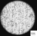
- FIG. 3 is a diagram showing an optical microscope image of Example 1.
- 10 is a diagram showing an optical microscope image of Comparative Example 3.
- FIG. It is a figure which shows the EBSD measurement result of Example 1.
- FIG. It is a figure which shows the cross-sectional SIM image of the copper foil sample of the comparative example 3.
- FIG. It is a figure which shows the cross-sectional SIM image of the copper foil sample of the comparative example 6.
- It is a figure which shows a bending test method.
- % means “% by mass” unless otherwise specified.
- the mechanism by which the developed shear band generates crystal grains having grain orientations that are locally different from the surroundings is as follows. First, a material that has been subjected to a shearing force during the rolling process of the material is deformed by the slip deformation of the crystal. However, if the strain increases as the rolling process proceeds, the material cannot be deformed only by the slip deformation, and the material is deformed by the shear deformation. I will go. Since this shear (deformation) band shears the crystal grains, the crystal grains are divided by the shear band. Furthermore, since the shear band is a structure in which strain is accumulated due to deformation, the driving force for generating new crystal grains during recrystallization annealing is high.
- the shear band is a structure that shears the crystal grains, and when observed from a cross section along the rolling parallel direction, the crystal grains are continuously divided at a predetermined depth in the thickness direction, and the crystal grains are at the end of the shear band. Remains without being divided in the thickness direction.
- the cross section is prepared using FIB (focused ion beam), and a shear band is determined by observing a SIM (scanning ion microscope) image of the cross section.
- the shear band is mainly formed by unevenness (indentations, oil pits, etc.) on the surface of the copper foil, and when the copper foil receives a shearing force, the unevenness becomes a bottleneck for material deformation. Deformation occurs as a starting point, and shear deformation tends to occur. Therefore, even in a relatively early stage of rolling, a shear band may develop in the depth direction immediately below such irregularities. For this reason, a technique for reducing the surface roughness in order to obtain the flexibility of the copper foil is conventionally known.
- the present inventors change the surface roughness of the rolling roll before the final pass of the final cold rolling, that is, before the final pass of the final cold rolling, the surface of the copper foil is not so rough.
- rolling with a low-roughness roll for example, rolling with a low-roughness roll
- roughening the surface of the copper foil in the final pass of the final cold rolling for example, rolling with a rough roll
- the final copper foil surface is roughened
- it has been found that the generation and development of shear bands can be suppressed, dishdown is reduced, and scratches are hardly generated on the surface when the copper foil is handled (example of the present invention in FIG. 1).
- the orientation of the copper foil has been thought to depend solely on the roughness of the copper foil surface, but in reality it does not only affect the roughness of the surface, but rather the size of the shear band inside the material. It was found that (development) affects the orientation (and dishdown). In the final cold rolling, if the material surface roughness can be suppressed sufficiently smoothly in the pass before the final pass, high orientation can be obtained even if the copper foil surface is finished rough in the final pass.
- the number of dishdowns does not necessarily correlate with the surface roughness. This is because a shear band does not necessarily exist immediately below the irregularities on the surface of the copper foil (see FIG. 8). Therefore, the depth of the unevenness on the surface of the copper foil itself does not determine the degree of development of the shear band.
- the degree of development of the shear band is suppressed, so the surface roughness and the number of dishdowns Is somewhat correlated.
- the surface of the copper foil is appropriately roughened, it is necessary to control (specify) the shear band itself, not the surface roughness of the copper foil.
- the present inventor directly specifies the degree of development of the shear band by the following index, thereby improving the flexibility of the copper foil having a moderately rough surface, suppressing the occurrence of dishdown, and copper. Succeeded in suppressing scratches on the surface when handling the foil.
- (1) Degree of development of shear band As an indicator of the degree of development of the shear band, the average value Lsa of the reach depth Ls of the shear band in the thickness direction of the copper foil as shown in FIG. On the other hand, the relationship of 0.01 ⁇ Lsa / t ⁇ 0.4 is satisfied. Note that Lsa (mm) / t (mm).
- FIG. 2 is a schematic diagram of the structure of a cross section along the rolling parallel direction and having a length of 25 ⁇ m in the rolling parallel direction RD of the copper foil.
- Three irregularities 4 are formed on the copper foil surface 2 a, and a shear band 10 extends in the thickness direction directly below the outer two irregularities of the irregularities 4.
- the symbol G represents a crystal grain
- the crystal grain G is a region surrounded by a grain boundary GB.
- the shear band 10 divides the crystal grains continuously in the thickness direction, but the grain boundary of the crystal grains not divided is the end of the shear band, and the depth in the plate thickness direction from the copper foil surface 2a to the end. Is defined as the reaching depth Ls of the shear band.
- Lsa is obtained by averaging Ls of each shear band observed in one visual field shown in FIG. 2, and similarly, the average value of Lsa obtained by observing the cross section of three visual fields is defined as Lsa. adopt.
- the shear band is directly under the unevenness
- 2) The shear band is almost straight, and it does not break or bend in the middle, and does not appear again after being interrupted.
- 3) The surface where the contrast of crystal grains is different is interfaced.
- both the shear band and the crystal grain boundary are visible at the interface in the metal structure observation.
- the difference between the shear band and the crystal grain boundary is that the grain boundary of the rolled material exists so as to surround one crystal grain, whereas the shear band is a straight line that continuously divides a plurality of crystal grains, and It exists in a certain angle with respect to a rolling parallel direction.
- the end can be a point at which the crystal grains are interrupted, that is, a point that abuts on a crystal grain having a single contrast.
- the surface of the copper foil is not made very rough before the final pass of the final cold rolling (for example, the surface roughness Ra is 0, for example). And rolling the surface of the copper foil in the final pass of the final cold rolling (for example, rolling with a rough roll having a surface roughness Ra of, for example, 0.06 ⁇ m or more). Is mentioned.
- Lsa / t is because the influence of the depth of the shear band differs depending on the plate thickness. Further, Lsa / t is preferably as small as possible, but the lower limit of Lsa / t is set to 0.01 from the viewpoint of practical production conditions of the copper foil.
- a cross-section of the copper foil is prepared using a focused ion beam, and a scanning ion microscope image of the cross-section is observed to determine the reaching depth Ls of the shear band.
- FIB focused ion beam
- a SIM scanning ion microscope
- a SIM scanning ion microscope
- the crystal is divided by a shear band. Grains can be distinguished with high accuracy.
- FIB for producing a cross section a Ga + ion beam can be used.
- two adjacent regions having a difference in contrast due to the SIM image are regarded as different crystal grains, and these boundaries are regarded as grain boundaries.
- deviated to RD direction is considered as the shear band 10, and this shift
- difference is connected in the thickness direction of copper foil.
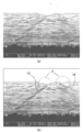
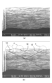
- FIG. 8 to 10 show cross-sectional SIM images of copper foil samples of Examples and Comparative Examples described later.
- FIG. 8 it can be seen that among the four irregularities 4, there are those in which the shear band 10 extends immediately below the irregularities and those in which no shear band occurs immediately below the irregularities. Further, it is possible to discriminate a portion (shear band) where the grain boundary just below the unevenness 4 is shifted in the RD direction from the contrast difference of the cross-section SIM image.
- a tangent L is drawn to two protrusions surrounding the depression A recessed from the copper foil surface 2a from the left and right, and the distance in the thickness direction between L and A is 0.1 ⁇ m or more. Concavity and convexity 4 are used.
- Ra / t Ra / t which is the ratio of the surface roughness Ra (mm) after the final cold rolling and the thickness t (mm) of the copper foil in order to reduce dishdown while moderately roughening the copper foil surface. Is defined as 0.004 or more and 0.007 or less. If it does in this way, dishdown can be reduced, making surface roughness equivalent to the conventional copper foil. In addition, by dividing the surface roughness by the thickness, the roughness of the copper foil surface can be evaluated regardless of the thickness of the copper foil.
- the surface roughness Ra (centerline average roughness) is defined in JIS B0601, and in the present invention, the copper foil surface has a length of 175 ⁇ m in the rolling parallel direction and is separated by 50 ⁇ m or more in the direction perpendicular to the rolling. The average value of the values measured on the straight line.
- the surface roughness can be measured using a contact surface roughness meter (SE-3400 manufactured by Kosaka Laboratory).
- all the copper foil surfaces and the surface roughness of a rolling roll shall be the said centerline average roughness.
- the average value d (mm) of the maximum depth of the oil pit is defined as d / t ⁇ 0.1.
- the average value d (mm) of the maximum depth of the oil pits is three as shown in FIG. 3 which is 175 ⁇ m long in the rolling parallel direction RD and 50 ⁇ m or more apart in the rolling perpendicular direction TD on the copper foil surface.
- the straight line L 1 ⁇ L 3 the average value of the difference between the maximum height H M and a minimum height H S in the thickness direction of the straight lines L 1 ⁇ L 3 which corresponds to the maximum depth of the oil pits di (mm) It is.
- the profile in the thickness direction on L 1 to L 3 is measured by contact-type roughness to obtain the maximum height H M (mm) and the minimum height H S (mm), and each straight line L 1 it is sufficient to average the di of ⁇ L 3.
- dishdown may occur even when d / t ⁇ 0.1.
- the thickness of the copper foil (or copper alloy foil) is not particularly limited, but for example, a thickness of 5 to 50 ⁇ m can be suitably used.
- the value of I / I 0 can be measured with a general X-ray diffraction measuring device. For example, it can measure using RINT2500 (made by Rigaku Corporation). In addition, a generally used element (for example, Cu, Co, etc.) may be used for the X-ray source.
- the workability of the final cold rolling is preferably 90% or more, and more preferably 95% or more. Further, it is further desirable that the workability of the final cold rolling is 98% or more.
- the angle difference from the [100] orientation is 15 degrees.
- the area ratio of the crystal grains is preferably 20% or less.
- the annealing at 200 ° C. for 30 minutes imitates the temperature history given to the copper foil in the CCL manufacturing process.
- the copper foil that has undergone the thermal history and the copper foil that has not received the heat are not distinguished. It was decided to heat for 30 minutes.
- the area ratio is less than 20% when observed by EBSD, the orientation difference between the crystal grains on the copper foil surface is small, and the proportion of crystal grains having different crystal orientations in a uniform structure is small. As a result, dents (dish down) due to etching are reduced, and scratches are unlikely to occur on the surface of the copper foil during handling.
- the material surface roughness is sufficiently smoothed in the pass before the final pass, that is, the final cool What is necessary is just to roll using a roll with comparatively small roughness (surface roughness Ra is 0.05 micrometer or less) by the pass before the last pass of a hot rolling.
- the copper foil tough pitch copper or oxygen-free copper having a purity of 99.9% or more can be used, and as the copper alloy foil, a known copper alloy can be used depending on the required strength and conductivity. Can be used.
- Known copper alloys include, for example, 0.004 to 0.3% tin-containing copper alloy, 0.004 to 0.05% silver-containing copper alloy, In, Zn, Zr, Ti, Fe, P, Ni , Si, Sn, Ag, Te, Cr, Nb, a copper alloy containing 0.004 to 0.5% in total of one or more elements of elements, and the like. 02% silver-added copper is often used.
- the rolled copper foil of this invention contains the alloy of the said composition other than pure copper type like tough pitch copper and oxygen-free copper.
- an example of the manufacturing method of the rolled copper foil of this invention is demonstrated.
- an ingot made of copper, necessary alloy elements, and inevitable impurities is hot-rolled, and then cold-rolling and annealing are repeated, and finally, it is finished to a predetermined thickness by final cold-rolling.
- the surface of the copper foil is not roughened before the final pass of the final cold rolling, and the final copper is roughened by roughening the surface of the copper foil in the final pass of the final cold rolling.
- the surface of the foil is rough, it becomes a surface state having oil pits which are difficult to develop in the shear band, and dishdown is reduced. And the surface ratio with such few shear bands has an oil pit area ratio of 6 to 15%.
- the surface of the copper foil is rolled by using a roll having a relatively small roughness (surface roughness Ra is, for example, 0.05 ⁇ m or less) What is necessary is just to roll by increasing the 1 pass processing degree in cold rolling.
- surface roughness Ra is, for example, 0.06 ⁇ m or more
- rolling is performed using a rolling oil having a high viscosity. The surface of the copper foil obtained is roughened.
- the annealing conditions may be adjusted so that the average grain size of recrystallized grains obtained by annealing immediately before the final cold rolling is 5 to 20 ⁇ m. Further, the rolling degree in the final cold rolling is preferably 90% or more.
- JXA8500F acceleration voltage 20 kV, current 2 ⁇ 10 ⁇ 8 A, measurement
- the range was 1000 ⁇ m ⁇ 1000 ⁇ m and the step width was 5 ⁇ m).
- the area ratio of crystal grains having an angle difference of 15 degrees or more from the [100] orientation was determined by image analysis.
- etching was performed for 2 minutes at room temperature using a ADEKA TECH CL-8 (manufactured by ADEKA Corporation) 20% solution, and the image obtained by photographing the etched surface with an optical microscope was binarized. The dark part exceeding 50 ⁇ m in the minor axis was counted as a dishdown.
- the surface of the copper foil after etching has a shape reflecting the crystal orientation, and the structure having the [100] orientation is a plane parallel to the copper foil surface, while the portion having the other crystal orientation is the crystal orientation. Unevenness caused by Therefore, the dishdown portion looks dark with an optical microscope.
- 4 shows an optical microscope image of Example 1
- FIG. 5 shows an optical microscope image of Comparative Example 3.
- 6 shows the EBSD measurement result of Example 1
- FIG. 7 shows the EBSD measurement result of Comparative Example 3. 6 and 7, gray and black regions indicate crystal grains having an angle difference of 15 degrees or more from the [100] orientation.
- the intermediate part of the copper foil 1 is bent into a hairpin shape with a predetermined radius of curvature r.
- the test conditions are as follows: Specimen width: 12.7 mm, Specimen length: 200 mm, Specimen sampling direction: Collected so that the length direction of the specimen is parallel to the rolling direction, curvature radius r : 1.0 mm (when copper foil thickness t is 0.009 mm), radius of curvature r: 1.5 mm (when copper foil thickness t is 0.012 mm), radius of curvature r: 2.5 mm (of copper foil) (When thickness t is 0.018 mm), vibration stroke: 25 mm, vibration speed: 1500 times / minute.
- the bending fatigue life is 20,000 times or more, it has excellent bendability, the bending fatigue life is evaluated as 50,000 times or more, and the bending fatigue life is 20,000 times or more and less than 50,000 times. Evaluation was set as (circle), and bending fatigue life was made into evaluation x with less than 20,000 times.
- the area ratio of crystal grains having an angle difference of 15 degrees or more from the [100] orientation exceeded 20%, and many dishdowns occurred.
- the surface roughness (Ry) of the copper foil surface after an etching was 1.51 micrometer. From this, it was found that dishdown may occur frequently even if the value of Ry is small.
- 8 to 10 show cross-sectional SIM images of the copper foil samples of Example 2, Comparative Example 3, and Comparative Example 6, respectively. It can be seen that the shear band 10 extends just below the irregularities 4. It can also be seen from the contrast difference in the cross-section SIM image that the portion (shear band) where the grain boundary just below the irregularities 4 is displaced in the RD direction can be determined. Furthermore, compared with Example 2 (FIG. 8), the comparative examples 3 and 4 have many deep shear bands 10, and the value of Lsa / t also becomes large. 8A to 10B, the reference symbol (a) indicates the cross-sectional SIM image itself, and the reference symbol (b) indicates that the determined shear band 10 is displayed on the cross-sectional SIM image.
Landscapes
- Chemical & Material Sciences (AREA)
- Engineering & Computer Science (AREA)
- Mechanical Engineering (AREA)
- Materials Engineering (AREA)
- Metallurgy (AREA)
- Organic Chemistry (AREA)
- Physics & Mathematics (AREA)
- Thermal Sciences (AREA)
- Crystallography & Structural Chemistry (AREA)
- Metal Rolling (AREA)
- Reduction Rolling/Reduction Stand/Operation Of Reduction Machine (AREA)
Abstract
【課題】銅箔表面を適度に粗くして取り扱い性を向上し、さらに屈曲性に優れるとともに、銅箔の取り扱い時に表面にキズが生じ難く、表面エッチング特性が良好な圧延銅箔を提供する。 【解決手段】表面粗さRaと、銅箔の厚みtとの比率Ra/tが0.004以上0.007以下であり、集束イオンビームを用い、銅箔の圧延平行方向に沿う長さ25μmの断面を作製し、該断面の走査イオン顕微鏡像を観察したとき、銅箔の厚み方向へのせん断帯の到達深さのLsの平均値Lsaが、銅箔の厚みtに対し、0.01≦Lsa/t≦0.4の関係を満たす圧延銅箔である。
Description
本発明は、屈曲性を要求されるFPCに好適に用いられる圧延銅箔に関する。
屈曲用FPC(フレキシブルプリント回路基板)に用いられる銅箔には高い屈曲性が求められる。銅箔に屈曲性を付与するための方法として、銅箔の(200)面の結晶方位の配向度を高める技術(特許文献1)、銅箔の板厚方向に貫通する結晶粒の割合を多くする技術(特許文献2)、銅箔のオイルピットの深さに相当する表面粗さRy(最大高さ)を2.0μm以下に低減する技術(特許文献3)が知られている。
一般的なFPC製造工程は以下のようなものである。まず銅箔を樹脂フィルムと接合する。接合には、銅箔上に塗布したワニスに熱処理を加えることでイミド化する方法や、接着剤付きの樹脂フィルムと銅箔とを重ねてラミネートする方法がある。これらの工程によって接合された樹脂フィルム付き銅箔をCCL(銅張積層板)と呼ぶ。このCCL製造工程における熱処理によって、銅箔は再結晶する。
ところで、銅箔を用いてFPCを製造する際、カバーレイフィルムとの密着性を向上させるために銅箔表面をエッチングすると、表面に直径数10μm程度のくぼみ(ディッシュダウン)が発生することがある。この原因は、再結晶焼鈍後に立方体組織が発達するように結晶方位を(200)面に制御した場合に全面が均一なエッチング速度となるのに対し、局部的に異なる結晶粒方位を持つ結晶粒が存在すると,その部分のみが周囲と異なるエッチング速度となり,周囲に比べて局部的に深いくぼみとなるためと考えられる。このくぼみは、回路のエッチング性を低下させたり、外観検査で不良と判定され歩留まりを低下させたりする原因となる。
ところで、銅箔を用いてFPCを製造する際、カバーレイフィルムとの密着性を向上させるために銅箔表面をエッチングすると、表面に直径数10μm程度のくぼみ(ディッシュダウン)が発生することがある。この原因は、再結晶焼鈍後に立方体組織が発達するように結晶方位を(200)面に制御した場合に全面が均一なエッチング速度となるのに対し、局部的に異なる結晶粒方位を持つ結晶粒が存在すると,その部分のみが周囲と異なるエッチング速度となり,周囲に比べて局部的に深いくぼみとなるためと考えられる。このくぼみは、回路のエッチング性を低下させたり、外観検査で不良と判定され歩留まりを低下させたりする原因となる。
このようなくぼみを低減する方法として、圧延前または圧延後に銅箔の表面に機械研磨を行って加工変質層となるひずみを与えた後、再結晶する技術(特許文献4)が報告されている。この技術によれば、加工変質層によって再結晶後に表面に不均一な結晶粒を群発させ、結晶方位の異なる結晶粒が単独で存在しないようになる。
一方、本出願人は、銅箔表面を適度に平滑にして上記したくぼみを低減しつつ、銅箔表面を平滑にし過ぎて通箔時の横滑り等が生じるのを防止するため、圧延直角方向の表面粗さRasを、圧延平行方向の表面粗さRapより粗くする技術を報告している(特許文献5)。
一方、本出願人は、銅箔表面を適度に平滑にして上記したくぼみを低減しつつ、銅箔表面を平滑にし過ぎて通箔時の横滑り等が生じるのを防止するため、圧延直角方向の表面粗さRasを、圧延平行方向の表面粗さRapより粗くする技術を報告している(特許文献5)。
しかしながら、特許文献4記載の技術の場合、不均一な結晶粒が多く、銅箔表面の結晶が(200)面に配向していないため、屈曲性が低下するという問題がある。
一方、銅箔の製造時のロールとの密着性を確保したり、銅箔製品の取り扱いを容易にするため、最終冷間圧延でのロール粗度を大きくして銅箔表面を粗くすることが行われているが、銅箔表面を粗くすると、銅箔表面の結晶の配向度が低下して屈曲性が劣ったり、ディッシュダウンが生じやすい。そのため、上述の特許文献5には、銅箔表面を適度に平滑にすべく、最終冷間圧延における圧延ロールの表面粗さRarollを0.05~0.15μmとし、かつその油膜当量を30000未満にすることが記載されている(特許文献5の段落0014)。ところが、この製造方法によって銅箔を製造すると、その取り扱い時に表面にキズが生じ易くなることが判明した(後述する実施例における「参考例」参照)。
すなわち、本発明は上記の課題を解決するためになされたものであり、取り扱い性を向上するために銅箔表面を適度に粗くしても,屈曲性を劣化させず,かつ表面にキズが生じ難く、表面のエッチング特性が良好な圧延銅箔の提供を目的とする。
一方、銅箔の製造時のロールとの密着性を確保したり、銅箔製品の取り扱いを容易にするため、最終冷間圧延でのロール粗度を大きくして銅箔表面を粗くすることが行われているが、銅箔表面を粗くすると、銅箔表面の結晶の配向度が低下して屈曲性が劣ったり、ディッシュダウンが生じやすい。そのため、上述の特許文献5には、銅箔表面を適度に平滑にすべく、最終冷間圧延における圧延ロールの表面粗さRarollを0.05~0.15μmとし、かつその油膜当量を30000未満にすることが記載されている(特許文献5の段落0014)。ところが、この製造方法によって銅箔を製造すると、その取り扱い時に表面にキズが生じ易くなることが判明した(後述する実施例における「参考例」参照)。
すなわち、本発明は上記の課題を解決するためになされたものであり、取り扱い性を向上するために銅箔表面を適度に粗くしても,屈曲性を劣化させず,かつ表面にキズが生じ難く、表面のエッチング特性が良好な圧延銅箔の提供を目的とする。
本発明者らは種々検討した結果、最終冷間圧延の最終パスの手前では銅箔の表面をあまり粗くせず(例えば、粗度の低いロールで圧延し)、最終冷間圧延の最終パスで銅箔の表面を粗くする(例えば、粗いロールで圧延する、つまり、最終冷間圧延の最終パスと、その手前で圧延ロールの粗さを変える)ことで、最終的な銅箔の表面を粗くしても、せん断帯が銅箔の厚み方向に深く到達せず、屈曲性を劣化させずにディッシュダウンが少なくなり、かつ銅箔の取り扱い時に表面にキズが生じ難くなることを見出した。
上記の目的を達成するために、本発明の圧延銅箔は、銅箔表面で圧延平行方向に長さ175μmで測定した表面粗さRaと、前記銅箔の厚みtとの比率Ra/tが0.004以上0.007以下であり、集束イオンビームを用い、前記銅箔の圧延平行方向に沿う長さ25μmの断面を作製し、該断面の走査イオン顕微鏡像を観察したとき、前記銅箔の厚み方向へのせん断帯の到達深さのLsの平均値Lsaが、前記銅箔の厚みtに対し、0.01≦Lsa/t≦0.4の関係を満たす。
上記の目的を達成するために、本発明の圧延銅箔は、銅箔表面で圧延平行方向に長さ175μmで測定した表面粗さRaと、前記銅箔の厚みtとの比率Ra/tが0.004以上0.007以下であり、集束イオンビームを用い、前記銅箔の圧延平行方向に沿う長さ25μmの断面を作製し、該断面の走査イオン顕微鏡像を観察したとき、前記銅箔の厚み方向へのせん断帯の到達深さのLsの平均値Lsaが、前記銅箔の厚みtに対し、0.01≦Lsa/t≦0.4の関係を満たす。
200℃で30分間加熱して再結晶組織に調質した状態において、圧延面のX線回折で求めた(200)面の強度(I)が、微粉末銅のX線回折で求めた(200)面の強度(I0)に対し、I/I0≧50であり、前記銅箔表面で圧延平行方向に長さ175μmで、かつ圧延直角方向にそれぞれ50μm以上離間する3本の直線上で、オイルピットの最大深さに相当する各直線の厚み方向の最大高さと最小高さの差の平均値dと、前記銅箔の厚みtとの比率d/tが0.1以下であることが好ましい。
さらに200℃×30分熱処理後の銅箔表面を電解研磨後にEBSDで観察した場合に、[100]方位からの角度差が15度以上の結晶粒の面積率が20%以下であることが好ましい。なお、ここでいう「さらに200℃×30分熱処理」とは、請求項2にて既に200℃で30分間加熱の熱履歴を受けた場合には、再度の熱処理をいう。
鋳塊を熱間圧延後、冷間圧延と焼鈍とを1回以上繰り返した後の最終冷間圧延工程において、最終パスの手前の圧延ロールの表面粗さを、最終パスの圧延ロールの表面粗さより平滑にすることが好ましい。ここで、圧延ロールの表面粗さは、JIS B0601に規定される中心線平均粗さである。
鋳塊を熱間圧延後、冷間圧延と焼鈍とを1回以上繰り返した後の最終冷間圧延工程において、最終パス前の段階で、Ra/tが0.002以上0.004以下であることが好ましい。
鋳塊を熱間圧延後、冷間圧延と焼鈍とを1回以上繰り返した後の最終冷間圧延工程において、最終パス前の段階で、Ra/tが0.002以上0.004以下であることが好ましい。
本発明によれば、銅箔表面を適度に粗くして取り扱い性を向上し、さらに屈曲性に優れるとともに、銅箔の取り扱い時に表面にキズが生じ難く、表面のエッチング特性が良好な圧延銅箔が得られる。
以下、本発明の実施形態に係る圧延銅箔について説明する。なお、本発明において%とは、特に断らない限り、質量%を示すものとする。
まず、図1を参照して、本発明の技術思想について説明する。最終冷間圧延でのロール粗度を大きくして銅箔表面を粗くすると、銅箔の取り扱い性は向上するが、ディッシュダウンが生じ易くなる(図1の従来例1)。
ディッシュダウンの発生は、粗いロールで冷間圧延することにより銅箔表面に凹凸が導入され、さらに厚み方向にせん断帯が深く発達することが原因であることがわかった。即ち、再結晶焼鈍により立方体組織が発達するように結晶方位を制御した場合、発達したせん断帯が周囲と局部的に異なる結晶粒方位を持つ結晶粒の起点となる。そして、その結晶粒が他の結晶粒と異なるエッチング速度を有するため、エッチングすると周囲に比べて局部的に深いくぼみとなる。
ディッシュダウンの発生は、粗いロールで冷間圧延することにより銅箔表面に凹凸が導入され、さらに厚み方向にせん断帯が深く発達することが原因であることがわかった。即ち、再結晶焼鈍により立方体組織が発達するように結晶方位を制御した場合、発達したせん断帯が周囲と局部的に異なる結晶粒方位を持つ結晶粒の起点となる。そして、その結晶粒が他の結晶粒と異なるエッチング速度を有するため、エッチングすると周囲に比べて局部的に深いくぼみとなる。
発達したせん断帯が、周囲と局部的に異なる結晶粒方位を持つ結晶粒を発生させるメカニズムは以下のとおりである。
まず、材料の圧延加工時に剪断力を受けた材料は、結晶のすべり変形により変形するが,圧延加工が進んで歪が増大すると、すべり変形だけでは変形できなくなり、剪断変形により材料が変形してゆくことになる。この剪断(変形)帯は結晶粒を剪断するため、せん断帯で結晶粒が分割される。さらに,せん断帯は変形により歪が蓄積された組織であるため、再結晶焼鈍時に新たな結晶粒を生成する駆動力が高い。従って、焼鈍時にせん断帯の周囲の結晶粒において(200)面が発達したとしても、せん断帯ではランダムな方位を持った結晶粒が生成すると考えられる。せん断帯のように周囲の組織と比較して歪の蓄積された組織は、材料全体(200)面の配向度を低下させるため、好ましくない。
まず、材料の圧延加工時に剪断力を受けた材料は、結晶のすべり変形により変形するが,圧延加工が進んで歪が増大すると、すべり変形だけでは変形できなくなり、剪断変形により材料が変形してゆくことになる。この剪断(変形)帯は結晶粒を剪断するため、せん断帯で結晶粒が分割される。さらに,せん断帯は変形により歪が蓄積された組織であるため、再結晶焼鈍時に新たな結晶粒を生成する駆動力が高い。従って、焼鈍時にせん断帯の周囲の結晶粒において(200)面が発達したとしても、せん断帯ではランダムな方位を持った結晶粒が生成すると考えられる。せん断帯のように周囲の組織と比較して歪の蓄積された組織は、材料全体(200)面の配向度を低下させるため、好ましくない。
なお、せん断帯は、結晶粒を剪断する組織であり、圧延平行方向に沿う断面から観察したときに、厚み方向に所定深さで結晶粒を連続して分断し、せん断帯の終端では結晶粒が厚み方向に分断されずに残っている。本発明では、詳しくは後述するようにFIB(集束イオンビーム)を用いて上記断面を作製し、この断面のSIM(走査イオン顕微鏡)像を観察してせん断帯を判別する。
ここで、せん断帯は、主に銅箔表面の凹凸(くぼみ,オイルピット等)が起点となって形成され、銅箔が剪断力を受けたとき、上記凹凸が材料変形のネックとなり、ここを起点として変形が生じて剪断変形となり易い。従って、比較的圧延の初期であっても,このような凹凸直下の深さ方向にはせん断帯が発達することがある。
このようなことから、銅箔の屈曲性を得るために表面粗さを低める手法が従来から知られている。これは、粗度の低いロールで最終冷間圧延することで、せん断帯の発生起点となる表面の凹凸を低減させ、銅箔の厚み方向にせん断帯が生じ難くなるためと考えられる。但し、銅箔の表面粗さを小さくすると、銅箔の取り扱い性が低下する(図1の従来例2)。
このようなことから、銅箔の屈曲性を得るために表面粗さを低める手法が従来から知られている。これは、粗度の低いロールで最終冷間圧延することで、せん断帯の発生起点となる表面の凹凸を低減させ、銅箔の厚み方向にせん断帯が生じ難くなるためと考えられる。但し、銅箔の表面粗さを小さくすると、銅箔の取り扱い性が低下する(図1の従来例2)。
以上から、本発明者は、最終冷間圧延の最終パスと、その手前で圧延ロールの表面粗さを変える、すなわち、最終冷間圧延の最終パスの手前では銅箔の表面をあまり粗くせず(例えば、粗度の低いロールで圧延し)、最終冷間圧延の最終パスで銅箔の表面を粗くする(例えば、粗いロールで圧延する)ことで、最終的な銅箔の表面を粗くしても、せん断帯の発生・発達を抑えることができ、ディッシュダウンが少なくなり、かつ銅箔の取り扱い時に表面にキズが生じ難くなることを見出した(図1の本発明例)。
つまり、従来、銅箔の配向性は単に銅箔表面の粗さに依存すると考えられてきたが、実際には表面の粗さのみに影響するのではなく、むしろ、材料内部のせん断帯の規模(発達度)が配向度(及びディッシュダウン)に影響することが分かった。そして、最終冷間圧延において、最終パス以前のパスで材料表面粗さを充分に平滑に抑制できれば、最終パスで銅箔表面を粗く仕上げても、高い配向性を得ることが出来る。
つまり、従来、銅箔の配向性は単に銅箔表面の粗さに依存すると考えられてきたが、実際には表面の粗さのみに影響するのではなく、むしろ、材料内部のせん断帯の規模(発達度)が配向度(及びディッシュダウン)に影響することが分かった。そして、最終冷間圧延において、最終パス以前のパスで材料表面粗さを充分に平滑に抑制できれば、最終パスで銅箔表面を粗く仕上げても、高い配向性を得ることが出来る。
ここで、ディッシュダウンの数と表面粗さとは必ずしも相関しない。これは、銅箔表面の凹凸の直下にせん断帯が必ず存在するわけではないからである(図8参照)。従って、銅箔表面の凹凸の深さ自体は、せん断帯の発達度を決定するものではない。但し、上記したように粗度の低いロールで最終冷間圧延し、銅箔の表面粗さを小さくした場合には、せん断帯の発達度が抑制されるため、表面粗さとディッシュダウンの数とはある程度相関がある。
しかしながら,本発明においては、銅箔表面を適度に粗くしているため、銅箔の表面粗さでなくせん断帯そのものを制御(規定)する必要がある。
しかしながら,本発明においては、銅箔表面を適度に粗くしているため、銅箔の表面粗さでなくせん断帯そのものを制御(規定)する必要がある。
そこで、本発明者は、以下の指標により、せん断帯の発達の程度を直接規定することで、適度に粗い表面を持つ銅箔の屈曲性を向上させ、ディッシュダウンの発生を抑制し、かつ銅箔の取り扱い時に表面にキズが生じるのを抑制することに成功した。
(1)せん断帯の発達の程度
せん断帯の発達程度の指標として、図2に示すように銅箔の厚み方向へのせん断帯の到達深さLsの平均値Lsaが、銅箔の厚みtに対し、0.01≦Lsa/t≦0.4の関係を満たすようにする。なお、Lsa (mm)/t(mm)とする。
図2は、銅箔の圧延平行方向RDに長さ25μmで、かつ該圧延平行方向に沿う断面の組織の模式図である。銅箔表面2aには3つの凹凸4が形成され、それら凹凸4のうち外側の2つの凹凸の直下に厚み方向にせん断帯10が延びている。ここで、符号Gは結晶粒を表し、結晶粒Gは粒界GBで囲まれた領域である。そして、せん断帯10は、厚み方向で結晶粒を連続して分断していくが、分断されない結晶粒の粒界をせん断帯の終端とし、銅箔表面2aから終端までの板厚方向の深さをせん断帯の到達深さLsと定義する。
なお、P1は、結晶粒がせん断帯10で分断され、粒界GBがずれた部分を示す。又、P2は、結晶粒がせん断帯10で分断されず、粒界GBがずれていない部分を示し、せん断帯の終端の位置となる。このようにして、図2に示す1視野で観察される各せん断帯のLsを平均化してLsaを求め、同様にして3視野の断面を観察してそれぞれ得られたLsaの平均値をLsaとして採用する。
(1)せん断帯の発達の程度
せん断帯の発達程度の指標として、図2に示すように銅箔の厚み方向へのせん断帯の到達深さLsの平均値Lsaが、銅箔の厚みtに対し、0.01≦Lsa/t≦0.4の関係を満たすようにする。なお、Lsa (mm)/t(mm)とする。
図2は、銅箔の圧延平行方向RDに長さ25μmで、かつ該圧延平行方向に沿う断面の組織の模式図である。銅箔表面2aには3つの凹凸4が形成され、それら凹凸4のうち外側の2つの凹凸の直下に厚み方向にせん断帯10が延びている。ここで、符号Gは結晶粒を表し、結晶粒Gは粒界GBで囲まれた領域である。そして、せん断帯10は、厚み方向で結晶粒を連続して分断していくが、分断されない結晶粒の粒界をせん断帯の終端とし、銅箔表面2aから終端までの板厚方向の深さをせん断帯の到達深さLsと定義する。
なお、P1は、結晶粒がせん断帯10で分断され、粒界GBがずれた部分を示す。又、P2は、結晶粒がせん断帯10で分断されず、粒界GBがずれていない部分を示し、せん断帯の終端の位置となる。このようにして、図2に示す1視野で観察される各せん断帯のLsを平均化してLsaを求め、同様にして3視野の断面を観察してそれぞれ得られたLsaの平均値をLsaとして採用する。
なお、1)せん断帯は凹凸の直下にあり、2)せん断帯はほぼ直線であり,途中で折れたり曲がったり,一旦途切れて再度現れることはなく、3)結晶粒のコントラストが異なる面を界面とすると,せん断帯も結晶粒界も金属組織観察上はどちらも界面に見える、という特徴がある。
そしてせん断帯と結晶粒界の違いは,圧延材の結晶粒界が一つの結晶粒を囲むように存在するのに対し、せん断帯は複数の結晶粒を連続で分断する直線であって、かつ圧延平行方向に対してある角度で存在することにある。又、凹凸から延びる直線の終端の区別のつきにくい場合は,結晶粒の分断が途切れる点,すなわちコントラストが一つである結晶粒に突き当たる点を終端とすることができる。
そしてせん断帯と結晶粒界の違いは,圧延材の結晶粒界が一つの結晶粒を囲むように存在するのに対し、せん断帯は複数の結晶粒を連続で分断する直線であって、かつ圧延平行方向に対してある角度で存在することにある。又、凹凸から延びる直線の終端の区別のつきにくい場合は,結晶粒の分断が途切れる点,すなわちコントラストが一つである結晶粒に突き当たる点を終端とすることができる。
又、0.01≦Lsa/t≦0.4の関係を満たす方法としては、最終冷間圧延の最終パスの手前では銅箔の表面をあまり粗くせず(例えば、表面粗さRaが例えば0.05μm以下の粗度の低いロールで圧延し)、最終冷間圧延の最終パスで銅箔の表面を粗くする(例えば、表面粗さRaが例えば0.06μm以上の粗いロールで圧延する)ことが挙げられる。
再結晶焼鈍時、せん断帯の周囲では(200)面の結晶方位に揃いにくく、(200)面の方位と異なる方位を持った結晶粒が生成しやすいが、発生のし易さはせん断帯の到達深さLsに関連する。そこで、0.01≦Lsa /t≦0.4の関係を満たすように制御することで、せん断帯の深さが全体的に浅くなり、(200)面の方位と異なる方位を持った結晶粒の発生が抑制され、ディッシュダウンが少なくなる。一方、Lsa /t>0.4の場合には、せん断帯が深く、(200)面の方位と異なる方位を持った結晶粒が多く発生し、ディッシュダウンが多数発生する。
なお、Lsa /tとして板厚tに対する比率としたのは、せん断帯の深さの影響が板厚によって異なるためである。又、Lsa/tは小さいほど好ましいが、銅箔の実用的な製造条件等の観点から、Lsa/tの下限を0.01としている。
なお、Lsa /tとして板厚tに対する比率としたのは、せん断帯の深さの影響が板厚によって異なるためである。又、Lsa/tは小さいほど好ましいが、銅箔の実用的な製造条件等の観点から、Lsa/tの下限を0.01としている。
本発明においては、銅箔の断面を集束イオンビームを用いて作製し、該断面の走査イオン顕微鏡像を観察してせん断帯の到達深さLsを判定する。
FIB(集束イオンビーム)は微細な加工が可能であり、平坦な断面が得られる。又、SIM(走査イオン顕微鏡)像は、集束イオンビームで試料を走査したとき放出される二次電子であり、組成や結晶方位のコントラストがSEM像より強くなるため、せん断帯で分断される結晶粒を精度よく判別することができる。断面を作製するためのFIBとしては、Ga+イオンビームを用いることができる。
又、本発明においては、SIM像によるコントラスト差がある2つの隣接領域をそれぞれ異なる結晶粒とみなし、これらの境界を粒界とみなす。そして、銅箔表面2aの凹凸4直下の粒界がRD方向にずれている部分をせん断帯10とみなし、銅箔の厚み方向にこのずれを繋げてゆく。粒界のRD方向のずれが見られなくなった位置をせん断帯の終端P2とし、銅箔表面2aからP2までの厚み方向の距離をLsとする。
FIB(集束イオンビーム)は微細な加工が可能であり、平坦な断面が得られる。又、SIM(走査イオン顕微鏡)像は、集束イオンビームで試料を走査したとき放出される二次電子であり、組成や結晶方位のコントラストがSEM像より強くなるため、せん断帯で分断される結晶粒を精度よく判別することができる。断面を作製するためのFIBとしては、Ga+イオンビームを用いることができる。
又、本発明においては、SIM像によるコントラスト差がある2つの隣接領域をそれぞれ異なる結晶粒とみなし、これらの境界を粒界とみなす。そして、銅箔表面2aの凹凸4直下の粒界がRD方向にずれている部分をせん断帯10とみなし、銅箔の厚み方向にこのずれを繋げてゆく。粒界のRD方向のずれが見られなくなった位置をせん断帯の終端P2とし、銅箔表面2aからP2までの厚み方向の距離をLsとする。
図8~図10は、後述する実施例及び比較例の銅箔試料の断面SIM像を示す。図8において、4個の凹凸4のうち、凹凸直下にせん断帯10が延びているものと、凹凸直下にせん断帯が生じないものがあることがわかる。又、断面SIM像のコントラスト差から、凹凸4直下の粒界がRD方向にずれている部分(せん断帯)を判別することができる。
なお、上記図8の断面像において、銅箔表面2aから窪むくぼみAを左右から囲む2つの突部に接線Lを引き、LとAとの厚み方向の距離が0.1μm以上のものを凹凸4とする。
なお、上記図8の断面像において、銅箔表面2aから窪むくぼみAを左右から囲む2つの突部に接線Lを引き、LとAとの厚み方向の距離が0.1μm以上のものを凹凸4とする。
次に、本発明の圧延銅箔のその他の規定及び組成について説明する。
(2)Ra/t
銅箔表面を適度に粗くしつつも、ディッシュダウンを少なくするため、最終冷間圧延後の表面粗さRa(mm)と銅箔の厚みt(mm)との比の値であるRa/tを0.004以上0.007以下に規定する。このようにすると、表面粗さを従来の銅箔と同等としつつ、ディッシュダウンを低減することができる。なお、表面粗さを厚みで割ることで、銅箔の厚みによらず銅箔表面の粗さの評価が行える。一方、Ra/tが0.004未満であると、銅箔表面が平滑になり過ぎ、銅箔の取り扱い時に表面にキズが生じ易くなる。Ra/tが0.007を超えると、銅箔表面が粗くなり過ぎ、銅箔表面の結晶の配向度が低下して屈曲性が劣ったり、ディッシュダウンが生じやすい。
ここで、表面粗さRa(中心線平均粗さ)はJIS B0601に規定され、本発明においては銅箔表面で圧延平行方向に長さ175μmで、かつ圧延直角方向にそれぞれ50μm以上離間する3本の直線上で測定した値の平均値とする。又、本発明において、表面粗さは接触表面粗さ計(小坂研究所製 SE-3400)を用いて測定することができる。なお、銅箔表面、及び圧延ロールの表面粗さはすべて、上記中心線平均粗さとする。
(2)Ra/t
銅箔表面を適度に粗くしつつも、ディッシュダウンを少なくするため、最終冷間圧延後の表面粗さRa(mm)と銅箔の厚みt(mm)との比の値であるRa/tを0.004以上0.007以下に規定する。このようにすると、表面粗さを従来の銅箔と同等としつつ、ディッシュダウンを低減することができる。なお、表面粗さを厚みで割ることで、銅箔の厚みによらず銅箔表面の粗さの評価が行える。一方、Ra/tが0.004未満であると、銅箔表面が平滑になり過ぎ、銅箔の取り扱い時に表面にキズが生じ易くなる。Ra/tが0.007を超えると、銅箔表面が粗くなり過ぎ、銅箔表面の結晶の配向度が低下して屈曲性が劣ったり、ディッシュダウンが生じやすい。
ここで、表面粗さRa(中心線平均粗さ)はJIS B0601に規定され、本発明においては銅箔表面で圧延平行方向に長さ175μmで、かつ圧延直角方向にそれぞれ50μm以上離間する3本の直線上で測定した値の平均値とする。又、本発明において、表面粗さは接触表面粗さ計(小坂研究所製 SE-3400)を用いて測定することができる。なお、銅箔表面、及び圧延ロールの表面粗さはすべて、上記中心線平均粗さとする。
(3)d/t
銅箔表面の粗さがそれほど大きくなく、オイルピットの多くはせん断帯があまり発達していないと考えられる場合でも、深いオイルピットが幾つか存在する場合がある。深いオイルピットではせん断帯が発達している可能性が高く、その場合には、ディッシュダウンの発生の起点となる。そこで、本発明では、オイルピットの最大深さの平均値d(mm)をd/t≦0.1に規定する。
オイルピットの最大深さの平均値d(mm)を厚みt(mm)で割ることで、銅箔の厚みによらず銅箔表面の評価が行える。すなわち、オイルピットの最大深さが同一であっても銅箔の厚みt(mm)が薄くなると、その影響が大きくなるためである。
ここでオイルピットの最大深さの平均値d(mm)は、図3に示すように銅箔表面で圧延平行方向RDに長さ175μmで、かつ圧延直角方向TDにそれぞれ50μm以上離間する3本の直線L1~L3上で、オイルピットの最大深さに相当する各直線L1~L3の厚み方向の最大高さHMと最小高さHSの差di(mm)の平均値である。具体的には、接触式粗さで、L1~L3上の厚み方向のプロファイルを測定して最大高さHM(mm)と最小高さHS(mm)を求め、各直線L1~L3のdiを平均すればよい。
なお、後述の比較例2のように、d/t≦0.1であってもディッシュダウンが発生する場合もある。
銅箔(又は銅合金箔)の厚みは特に制限されないが、例えば5~50μmのものを好適に用いることができる。
銅箔表面の粗さがそれほど大きくなく、オイルピットの多くはせん断帯があまり発達していないと考えられる場合でも、深いオイルピットが幾つか存在する場合がある。深いオイルピットではせん断帯が発達している可能性が高く、その場合には、ディッシュダウンの発生の起点となる。そこで、本発明では、オイルピットの最大深さの平均値d(mm)をd/t≦0.1に規定する。
オイルピットの最大深さの平均値d(mm)を厚みt(mm)で割ることで、銅箔の厚みによらず銅箔表面の評価が行える。すなわち、オイルピットの最大深さが同一であっても銅箔の厚みt(mm)が薄くなると、その影響が大きくなるためである。
ここでオイルピットの最大深さの平均値d(mm)は、図3に示すように銅箔表面で圧延平行方向RDに長さ175μmで、かつ圧延直角方向TDにそれぞれ50μm以上離間する3本の直線L1~L3上で、オイルピットの最大深さに相当する各直線L1~L3の厚み方向の最大高さHMと最小高さHSの差di(mm)の平均値である。具体的には、接触式粗さで、L1~L3上の厚み方向のプロファイルを測定して最大高さHM(mm)と最小高さHS(mm)を求め、各直線L1~L3のdiを平均すればよい。
なお、後述の比較例2のように、d/t≦0.1であってもディッシュダウンが発生する場合もある。
銅箔(又は銅合金箔)の厚みは特に制限されないが、例えば5~50μmのものを好適に用いることができる。
(4)I/I0
本発明の銅箔に、高屈曲性を付与するため、200℃で30分間加熱して再結晶組織に調質した状態において、圧延面のX線回折で求めた(200)面の強度(I)を、微粉末銅のX線回折で求めた(200)面の強度(I0)に対し、I/I0≧50に規定する。これにより、屈曲性に優れた(200)面の配向度が高まる。I/I0<50になると、屈曲性が低下する。上記200℃で30分の焼鈍は、CCL製造工程において銅箔に付与される温度履歴を模したものである。なお、I/I0の値は一般的なX線回折の測定装置であれば測定できる。たとえばRINT2500(株式会社リガク製)を用いて測定することができる。また、X線源には一般的に用いられる元素(例えば、Cu、Co等)を使用すれば良い。
なお、I/I0≧50となるためには、最終冷間圧延の加工度が90%以上であることが好ましく、95%以上であることがより望ましい。また、最終冷間圧延の加工度が98%以上であることが更に望ましい。
本発明の銅箔に、高屈曲性を付与するため、200℃で30分間加熱して再結晶組織に調質した状態において、圧延面のX線回折で求めた(200)面の強度(I)を、微粉末銅のX線回折で求めた(200)面の強度(I0)に対し、I/I0≧50に規定する。これにより、屈曲性に優れた(200)面の配向度が高まる。I/I0<50になると、屈曲性が低下する。上記200℃で30分の焼鈍は、CCL製造工程において銅箔に付与される温度履歴を模したものである。なお、I/I0の値は一般的なX線回折の測定装置であれば測定できる。たとえばRINT2500(株式会社リガク製)を用いて測定することができる。また、X線源には一般的に用いられる元素(例えば、Cu、Co等)を使用すれば良い。
なお、I/I0≧50となるためには、最終冷間圧延の加工度が90%以上であることが好ましく、95%以上であることがより望ましい。また、最終冷間圧延の加工度が98%以上であることが更に望ましい。
(5)EBSDによる方位差
200℃で30分間加熱して再結晶組織に調質した状態において、銅箔表面を電解研磨後にEBSDで観察した場合に、[100]方位からの角度差が15度以上の結晶粒の面積率が20%以下であることが好ましい。上記200℃30分の焼鈍は、CCL製造工程において銅箔に付与される温度履歴を模したものである。なお、すでに熱履歴を受けているCCLとなった銅箔についても、200℃で30分間加熱してよい。一度再結晶するまで熱処理されたものは、それ以上加熱してもほぼ変化しないため、EBSDで観察の観察においては、熱履歴を受けた銅箔、受けない銅箔を区別せず、200℃で30分間加熱することとした。
EBSDで観察した場合に上記面積率が20%未満であれば、銅箔表面の結晶粒同士の方位差が小さく、均一な組織の中に結晶方位の異なる結晶粒が単独で存在する割合が少なくなるので、エッチングによるくぼみ(ディッシュダウン)が低減し、さらに銅箔の取り扱い時に表面にキズが生じ難い。なお、EBSDで観察した場合に上記面積率を20%未満とするには、上記したように最終冷間圧延において、最終パス以前のパスで材料表面粗さを充分に平滑にする、つまり最終冷間圧延の最終パス以前のパスで粗さ(表面粗さRaが例えば0.05μm以下)が比較的小さいロールを用いて圧延すればよい。
200℃で30分間加熱して再結晶組織に調質した状態において、銅箔表面を電解研磨後にEBSDで観察した場合に、[100]方位からの角度差が15度以上の結晶粒の面積率が20%以下であることが好ましい。上記200℃30分の焼鈍は、CCL製造工程において銅箔に付与される温度履歴を模したものである。なお、すでに熱履歴を受けているCCLとなった銅箔についても、200℃で30分間加熱してよい。一度再結晶するまで熱処理されたものは、それ以上加熱してもほぼ変化しないため、EBSDで観察の観察においては、熱履歴を受けた銅箔、受けない銅箔を区別せず、200℃で30分間加熱することとした。
EBSDで観察した場合に上記面積率が20%未満であれば、銅箔表面の結晶粒同士の方位差が小さく、均一な組織の中に結晶方位の異なる結晶粒が単独で存在する割合が少なくなるので、エッチングによるくぼみ(ディッシュダウン)が低減し、さらに銅箔の取り扱い時に表面にキズが生じ難い。なお、EBSDで観察した場合に上記面積率を20%未満とするには、上記したように最終冷間圧延において、最終パス以前のパスで材料表面粗さを充分に平滑にする、つまり最終冷間圧延の最終パス以前のパスで粗さ(表面粗さRaが例えば0.05μm以下)が比較的小さいロールを用いて圧延すればよい。
(6)組成
銅箔としては、純度99.9%以上のタフピッチ銅、無酸素銅を用いることができ、又、銅合金箔としては要求される強度や導電性に応じて公知の銅合金を用いることができる。公知の銅合金としては、例えば、0.004~0.3%の錫入り銅合金や0.004~0.05%の銀入り銅合金、In、Zn、Zr、Ti、Fe、P、Ni、Si、Sn、Ag、Te、Cr、Nb、Vからなる元素の一種以上を合計で0.004~0.5%含む銅合金等が挙げられ、中でも、導電性に優れたものとして0.02%銀添加銅がよく用いられる。
このように、本発明の圧延銅箔は、タフピッチ銅、無酸素銅のような純銅系の他、上記組成の合金をも含む。
銅箔としては、純度99.9%以上のタフピッチ銅、無酸素銅を用いることができ、又、銅合金箔としては要求される強度や導電性に応じて公知の銅合金を用いることができる。公知の銅合金としては、例えば、0.004~0.3%の錫入り銅合金や0.004~0.05%の銀入り銅合金、In、Zn、Zr、Ti、Fe、P、Ni、Si、Sn、Ag、Te、Cr、Nb、Vからなる元素の一種以上を合計で0.004~0.5%含む銅合金等が挙げられ、中でも、導電性に優れたものとして0.02%銀添加銅がよく用いられる。
このように、本発明の圧延銅箔は、タフピッチ銅、無酸素銅のような純銅系の他、上記組成の合金をも含む。
次に、本発明の圧延銅箔の製造方法の一例について説明する。まず、銅及び必要な合金元素、さらに不可避不純物からなる鋳塊を熱間圧延後、冷間圧延と焼鈍とを繰り返し、最後に最終冷間圧延で所定厚みに仕上げる。
ここで、上記したように、最終冷間圧延の最終パスの手前では銅箔の表面をあまり粗くせず、最終冷間圧延の最終パスで銅箔の表面を粗くすることで、最終的な銅箔の表面を粗いが、せん断帯に発達しにくいオイルピットを有する表面状態となり、ディッシュダウンが少なくなる。そして、このようなせん断帯が少ない表面は、オイルピットの面積率が6以上15%以下となる。
ここで、上記したように、最終冷間圧延の最終パスの手前では銅箔の表面をあまり粗くせず、最終冷間圧延の最終パスで銅箔の表面を粗くすることで、最終的な銅箔の表面を粗いが、せん断帯に発達しにくいオイルピットを有する表面状態となり、ディッシュダウンが少なくなる。そして、このようなせん断帯が少ない表面は、オイルピットの面積率が6以上15%以下となる。
従って、最終冷間圧延の最終パスの手前では、銅箔の表面をあまり粗くしないよう、粗さ(表面粗さRaが例えば0.05μm以下)が比較的小さいロールを用いて圧延したり、最終冷間圧延における1パス加工度を大きくして圧延すればよい。一方、最終冷間圧延の最終パスでは、粗さ(表面粗さRaが例えば0.06μm以上)が比較的大きいロールを用いて圧延したり、粘度の高い圧延油を用いて圧延し、最終的に得られる銅箔表面を粗くする。
なお、最終的な銅箔の表面を粗いが、せん断帯に発達しにくいオイルピットを有する表面状態を作り込むためには、最終冷間圧延の最終2パス、又は最終パスで、上記したように粗いロールを用いたり粘度の高い圧延油を用いて圧延することが必要であるが、調整し易いことから最終パスでの圧延条件を調整することが好ましい。一方、最終冷間圧延の最終3パス以前からロールの粗さを粗くすると、形成されたオイルピットに更に最終パスの加工によってせん断帯が発達する。
なお、最終的な銅箔の表面を粗いが、せん断帯に発達しにくいオイルピットを有する表面状態を作り込むためには、最終冷間圧延の最終2パス、又は最終パスで、上記したように粗いロールを用いたり粘度の高い圧延油を用いて圧延することが必要であるが、調整し易いことから最終パスでの圧延条件を調整することが好ましい。一方、最終冷間圧延の最終3パス以前からロールの粗さを粗くすると、形成されたオイルピットに更に最終パスの加工によってせん断帯が発達する。
なお、最終冷間圧延の直前の焼鈍で得られる再結晶粒の平均粒径が5~20μmになるよう、焼鈍条件下を調整するとよい。又、最終冷間圧延での圧延加工度を90%以上とするとよい。
表1に記載した組成の銅または銅合金を原料としてインゴットを鋳造し、800℃以上で厚さ10mmまで熱間圧延を行い、表面の酸化スケールを面削した後、冷間圧延と焼鈍とを繰り返し、最後に最終冷間圧延で厚み0.009~0.018mmに仕上げた。最終冷間圧延での圧延加工度を95~99.8%とした。なお、表1中、タフピッチ銅をTPC、無酸素銅をOFCと記載した。無酸素銅はJIS-H0500(C1011)に規格され、タフピッチ銅はJIS-H0500(C1100)に規格されている。
なお、最終冷間圧延は10~15パスで行い、表1に示すように、最終パスの手前までのロールの表面粗さ、及び最終パスのロールの表面粗さを変えて圧延を行った。最終圧延の1パス目から最終パスの手前までのロールの表面粗さはすべて同じである。
又、「参考例6~9」として、特許文献5の製造方法に従い、最終冷間圧延工程の最終パスの手前と最終パスとで、圧延ロールの表面粗さを同一として銅箔試料を製造した。なお、参考例6~9は、それぞれ特許文献5の実施例4,1,3,6に対応する(特許文献5の表1参照)。
なお、最終冷間圧延は10~15パスで行い、表1に示すように、最終パスの手前までのロールの表面粗さ、及び最終パスのロールの表面粗さを変えて圧延を行った。最終圧延の1パス目から最終パスの手前までのロールの表面粗さはすべて同じである。
又、「参考例6~9」として、特許文献5の製造方法に従い、最終冷間圧延工程の最終パスの手前と最終パスとで、圧延ロールの表面粗さを同一として銅箔試料を製造した。なお、参考例6~9は、それぞれ特許文献5の実施例4,1,3,6に対応する(特許文献5の表1参照)。
このようにして得られた各銅箔試料について、諸特性の評価を行った。
(1)せん断帯
集束イオンビーム(FIB)を用い、図2に示すように、銅箔の圧延平行方向RDに沿う長さ100μmの断面を作製し、該断面の走査イオン顕微鏡像を観察した。上記断面のうち、RDに沿う長さ25μmを1視野として、4視野観察した。せん断帯の判別方法は図2で説明したとおりである。FIB装置は、エスアイアイ・ナノテクノロジー株式会社製の製品名「N Vision 40」を用いた。
(2)立方体集合組織
試料を200℃で30分間加熱した後、圧延面のX線回折で求めた(200)面強度の積分値(I)を求めた。この値をあらかじめ測定しておいた微粉末銅(325mesh,水素気流中で300℃で1時間加熱してから使用)の(200)面強度の積分値(I0 )で割り、I/I0 値を計算した。
(1)せん断帯
集束イオンビーム(FIB)を用い、図2に示すように、銅箔の圧延平行方向RDに沿う長さ100μmの断面を作製し、該断面の走査イオン顕微鏡像を観察した。上記断面のうち、RDに沿う長さ25μmを1視野として、4視野観察した。せん断帯の判別方法は図2で説明したとおりである。FIB装置は、エスアイアイ・ナノテクノロジー株式会社製の製品名「N Vision 40」を用いた。
(2)立方体集合組織
試料を200℃で30分間加熱した後、圧延面のX線回折で求めた(200)面強度の積分値(I)を求めた。この値をあらかじめ測定しておいた微粉末銅(325mesh,水素気流中で300℃で1時間加熱してから使用)の(200)面強度の積分値(I0 )で割り、I/I0 値を計算した。
(3)オイルピットの最大深さ(平均値d)
コンフォーカル顕微鏡(レーザーテック社製、型番:HD100D)を用い、図3に示すようにして、銅箔表面で圧延平行方向RDに長さ175μmで、かつ圧延直角方向TDにそれぞれ50μm以上離間する3本の直線L1~L3上の最大高さHMと最小高さHSの差diをそれぞれ求めた。各直線L1~L3のdiを平均してdとした。なお、d(mm)/t(mm)とした。
(4)EBSDによる方位差
(2)で加熱した後の試料表面を電解研磨後にEBSD(後方散乱電子線回析装置、日本電子株式会社JXA8500F、加速電圧20kV、電流2×10⁻⁸A、測定範囲1000μm×1000μm、ステップ幅5μm)で観察した。[100]方位からの角度差が15度以上の結晶粒の面積率を画像解析で求めた。そして、この観察範囲を含む試料について、アデカテックCL-8(株式会社アデカ製)20%溶液を用いて常温で2分間エッチングを行い、エッチング後の表面を光学顕微鏡で撮影した画像を明暗二値化し、短径50μmを越える暗部をディッシュダウンとして数えた。なお、エッチング後の銅箔表面は結晶方位を反映した形状となり、[100]方位を持った組織は銅箔表面に平行な面となるのに対し、その他の結晶方位を持った部分は結晶方位に起因する凹凸ができる。従って、ディッシュダウンの部分は光学顕微鏡で暗く見えることになる。
なお、図4は実施例1の光学顕微鏡像を示し、図5は比較例3の光学顕微鏡像を示す。又、図6は実施例1のEBSD測定結果を示し、図7は比較例3のEBSD測定結果を示す。図6、図7において、灰色や黒色の領域が[100]方位からの角度差が15度以上の結晶粒を示す。
コンフォーカル顕微鏡(レーザーテック社製、型番:HD100D)を用い、図3に示すようにして、銅箔表面で圧延平行方向RDに長さ175μmで、かつ圧延直角方向TDにそれぞれ50μm以上離間する3本の直線L1~L3上の最大高さHMと最小高さHSの差diをそれぞれ求めた。各直線L1~L3のdiを平均してdとした。なお、d(mm)/t(mm)とした。
(4)EBSDによる方位差
(2)で加熱した後の試料表面を電解研磨後にEBSD(後方散乱電子線回析装置、日本電子株式会社JXA8500F、加速電圧20kV、電流2×10⁻⁸A、測定範囲1000μm×1000μm、ステップ幅5μm)で観察した。[100]方位からの角度差が15度以上の結晶粒の面積率を画像解析で求めた。そして、この観察範囲を含む試料について、アデカテックCL-8(株式会社アデカ製)20%溶液を用いて常温で2分間エッチングを行い、エッチング後の表面を光学顕微鏡で撮影した画像を明暗二値化し、短径50μmを越える暗部をディッシュダウンとして数えた。なお、エッチング後の銅箔表面は結晶方位を反映した形状となり、[100]方位を持った組織は銅箔表面に平行な面となるのに対し、その他の結晶方位を持った部分は結晶方位に起因する凹凸ができる。従って、ディッシュダウンの部分は光学顕微鏡で暗く見えることになる。
なお、図4は実施例1の光学顕微鏡像を示し、図5は比較例3の光学顕微鏡像を示す。又、図6は実施例1のEBSD測定結果を示し、図7は比較例3のEBSD測定結果を示す。図6、図7において、灰色や黒色の領域が[100]方位からの角度差が15度以上の結晶粒を示す。
(5)表面の傷
各試料の表面を目視し、圧延方向に10mm以上の長さをもつ傷が、5箇所/m2以上ある場合を×とした。
(6)屈曲性
試料を200℃で30分間加熱して再結晶させた後、図11に示す屈曲試験装置により、屈曲疲労寿命の測定を行った。この装置は、発振駆動体4に振動伝達部材3を結合した構造になっており、被試験銅箔1は、矢印で示したねじ2の部分と3の先端部の計4点で装置に固定される。振動部3が上下に駆動すると、銅箔1の中間部は、所定の曲率半径rでヘアピン状に屈曲される。本試験では、以下の条件下で屈曲を繰り返した時の破断までの回数を求めた。
なお、試験条件は次の通りである:試験片幅:12.7mm、試験片長さ:200mm、試験片採取方向:試験片の長さ方向が圧延方向と平行になるように採取、曲率半径r:1.0mm(銅箔の厚みtが0.009mmの場合)、曲率半径r:1.5mm(銅箔の厚みtが0.012mmの場合)、曲率半径r:2.5mm(銅箔の厚みtが0.018mmの場合)、振動ストローク:25mm、振動速度:1500回/分。
なお、屈曲疲労寿命が2万回以上の場合に優れた屈曲性を有しているとし、屈曲疲労寿命が5万回以上を評価◎とし、屈曲疲労寿命が2万回以上5万回未満を評価を○とし、屈曲疲労寿命が2万回未満を評価×とした。
各試料の表面を目視し、圧延方向に10mm以上の長さをもつ傷が、5箇所/m2以上ある場合を×とした。
(6)屈曲性
試料を200℃で30分間加熱して再結晶させた後、図11に示す屈曲試験装置により、屈曲疲労寿命の測定を行った。この装置は、発振駆動体4に振動伝達部材3を結合した構造になっており、被試験銅箔1は、矢印で示したねじ2の部分と3の先端部の計4点で装置に固定される。振動部3が上下に駆動すると、銅箔1の中間部は、所定の曲率半径rでヘアピン状に屈曲される。本試験では、以下の条件下で屈曲を繰り返した時の破断までの回数を求めた。
なお、試験条件は次の通りである:試験片幅:12.7mm、試験片長さ:200mm、試験片採取方向:試験片の長さ方向が圧延方向と平行になるように採取、曲率半径r:1.0mm(銅箔の厚みtが0.009mmの場合)、曲率半径r:1.5mm(銅箔の厚みtが0.012mmの場合)、曲率半径r:2.5mm(銅箔の厚みtが0.018mmの場合)、振動ストローク:25mm、振動速度:1500回/分。
なお、屈曲疲労寿命が2万回以上の場合に優れた屈曲性を有しているとし、屈曲疲労寿命が5万回以上を評価◎とし、屈曲疲労寿命が2万回以上5万回未満を評価を○とし、屈曲疲労寿命が2万回未満を評価×とした。
(7)エッチング後の銅箔表面の表面粗さ(Ry)
後述の比較例2、6については本発明の効果を明らかにするため以下の方法によりエッチング後の銅箔表面の表面粗さ(Ry)を測定した。
温度50℃,濃度100g/Lの過硫酸ナトリウム水溶液を試料表面に,2 kg/cm2 の圧力で噴射し,深さ方向に約9μm減肉エッチングした。その後,JIS B0601に従い,接触粗さ計を用いて表面の最大高さ(Ry)を求めた。基準長さを0.8 mmとし,圧延方向と平行な方向に測定した。Ryの測定は場所を変えて5回行い,5回の測定値の最大値を求めた。
後述の比較例2、6については本発明の効果を明らかにするため以下の方法によりエッチング後の銅箔表面の表面粗さ(Ry)を測定した。
温度50℃,濃度100g/Lの過硫酸ナトリウム水溶液を試料表面に,2 kg/cm2 の圧力で噴射し,深さ方向に約9μm減肉エッチングした。その後,JIS B0601に従い,接触粗さ計を用いて表面の最大高さ(Ry)を求めた。基準長さを0.8 mmとし,圧延方向と平行な方向に測定した。Ryの測定は場所を変えて5回行い,5回の測定値の最大値を求めた。
得られた結果を表1、表2に示す。

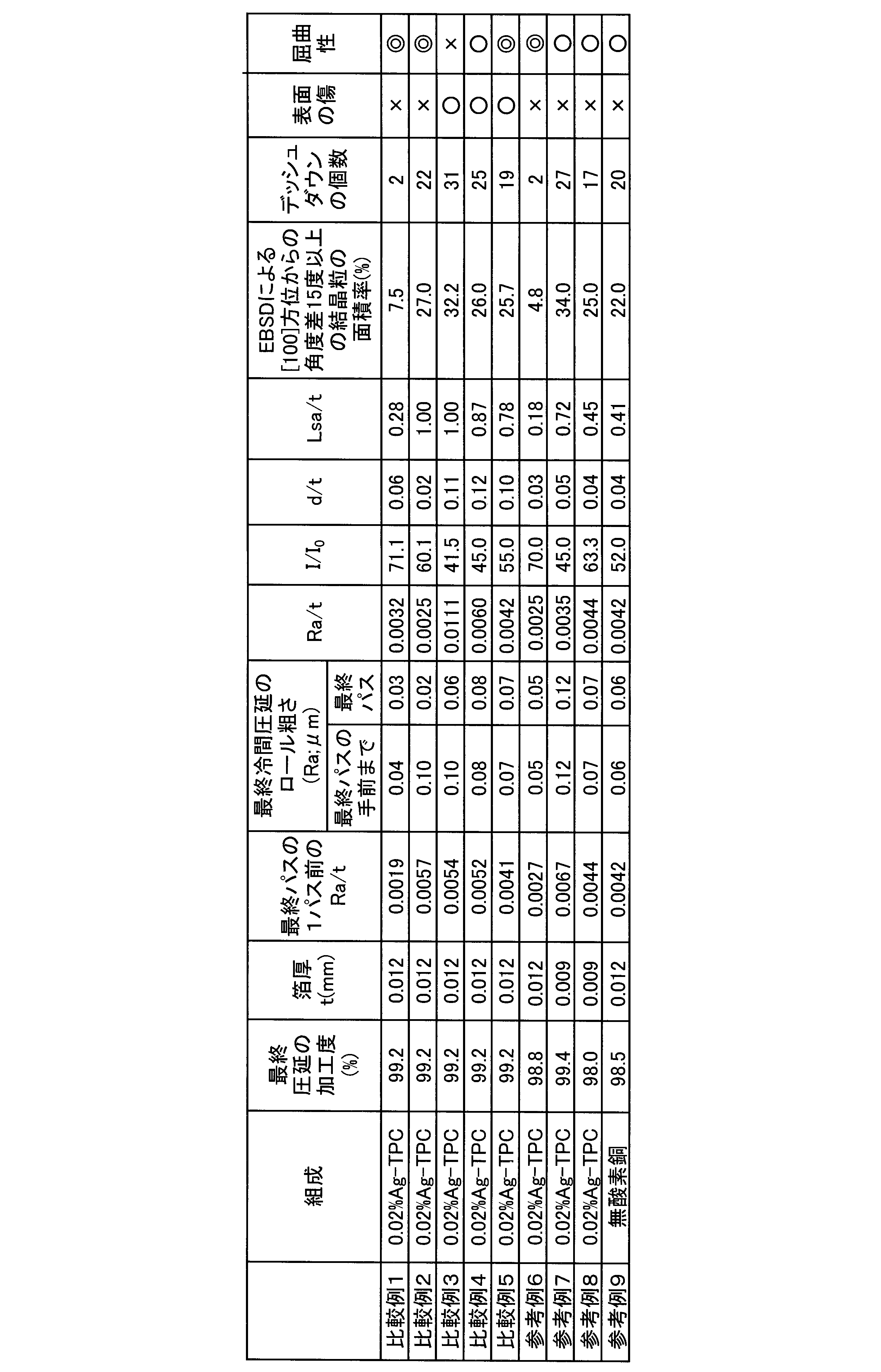
表1、表2から明らかなように、最終製品のRa/tが0.004以上0.007以下かつ、Lsa/t≦0.4である各実施例の場合、ディッシュダウンの個数が少なく、さらに銅箔表面に傷がなく、屈曲性にも優れていた。又、各実施例の場合、EBSDによる[100]方位からの角度差が15度以上の結晶粒の面積率が20%未満となった。
一方、最終冷間圧延のすべてのパス(最終パス含む)のロールの表面粗さをいずれもRa=0.04μm以下とした比較例1の場合、最終パスのRa/tが0.004未満となったため銅箔表面に傷が付き、取り扱い性に劣った。
最終冷間圧延で、最終パスの手前までのロールの表面粗さをRa=0.06μm以上に粗くし、最終パスのロールの表面粗さをRa=0.05μm以下とした比較例2の場合、最終製品のRa/tが0.004より小さくなったため、銅箔表面に傷が付いて取り扱い性に劣った。又、最終パスの手前では粗いロールを用いたため、最終パス前の銅箔表面が粗くなり、最終パスで粗さの小さいロールを用いてもせん断帯が形成された。そのため、d/tが0.1以下であったが、Lsa/tの値が0.4を越えた。その結果、[100]方位からの角度差が15度以上の結晶粒の面積率が20%を超え、ディッシュダウンが多数発生した。
また、比較例2の場合、エッチング後の銅箔表面の表面粗さ(Ry)は1.51μmであった。これより、Ryの値が小さくても、ディッシュダウンが多発する場合があることが分かった。
また、比較例2の場合、エッチング後の銅箔表面の表面粗さ(Ry)は1.51μmであった。これより、Ryの値が小さくても、ディッシュダウンが多発する場合があることが分かった。
最終冷間圧延で、最終パスの手前までのロールの表面粗さ、及び最終パスのロールの表面粗さをいずれもRa=0.06μm以上に粗くした比較例3、4、5の場合、最終パスの1パス前のRa/tが0.004以上と銅箔表面が粗くなり、最終パス後にせん断帯が発達した。そのため、Lsa/tが0.4を超え、ディッシュダウンが多数発生した。又、[100]方位からの角度差が15度以上の結晶粒の面積率が20%を超えた。
なお、比較例3、4の場合、最終冷間圧延のすべてのパスのロール表面粗さを粗くしたため、材料内部でせん断帯が著しく発達したオイルピットが多数発生した。このため、Lsa/tが0.4を超えただけでなく、銅箔表面の結晶の配向度が低下し、I/I0<50となった。それに応じ、[100]方位からの角度差が15度以上の結晶粒の面積率が20%を超えた。一方、比較例5の場合、最終パスの手前までのロールの粗さを比較例3、4より平滑としたため、I/I0は50以上となって比較例3、4よりも高い値となり、屈曲性は良好であった。
また、比較例5のエッチング後の銅箔表面の表面粗さ(Ry)は2.49μmであった。
なお、比較例3、4の場合、最終冷間圧延のすべてのパスのロール表面粗さを粗くしたため、材料内部でせん断帯が著しく発達したオイルピットが多数発生した。このため、Lsa/tが0.4を超えただけでなく、銅箔表面の結晶の配向度が低下し、I/I0<50となった。それに応じ、[100]方位からの角度差が15度以上の結晶粒の面積率が20%を超えた。一方、比較例5の場合、最終パスの手前までのロールの粗さを比較例3、4より平滑としたため、I/I0は50以上となって比較例3、4よりも高い値となり、屈曲性は良好であった。
また、比較例5のエッチング後の銅箔表面の表面粗さ(Ry)は2.49μmであった。
図8~図10は、それぞれ実施例2、比較例3、比較例6の銅箔試料の断面SIM像を示す。凹凸4の直下にせん断帯10が延びていることがわかる。又、断面SIM像のコントラスト差から、凹凸4直下の粒界がRD方向にずれている部分(せん断帯)を判別することができることがわかる。さらに、実施例2(図8)に比べ、比較例3、4の方が深いせん断帯10が多く、Lsa/tの値も大きくなる。
なお、図8~図10の符号(a)は断面SIM像そのものを示し、符号(b)は判別したせん断帯10を断面SIM像上に表示したものを示す。
なお、図8~図10の符号(a)は断面SIM像そのものを示し、符号(b)は判別したせん断帯10を断面SIM像上に表示したものを示す。
又、最終冷間圧延工程の最終パスの手前と最終パスとで、圧延ロールの表面粗さを同一とした参考例6~9の場合、いずれもディッシュダウンが多数発生したと共に、表面のキズが目立ち、取扱い性が劣った。
なお、参考例6の場合、最終冷間圧延工程の最終パスの手前と最終パスとで、圧延ロールの表面粗さがいずれも平滑(Ra=0.05μm)であるため、Lsa/tは0.4以下であったが、Ra/tが0.004未満となり、表面のキズが目立った。
一方、参考例7~9の場合、最終冷間圧延工程の最終パスの手前と最終パスとで、圧延ロールの表面粗さがいずれも粗い(Raが0.05μmを超える)ため、Lsa/tが0.4を超え、表面のキズが目立った。
なお、参考例6の場合、最終冷間圧延工程の最終パスの手前と最終パスとで、圧延ロールの表面粗さがいずれも平滑(Ra=0.05μm)であるため、Lsa/tは0.4以下であったが、Ra/tが0.004未満となり、表面のキズが目立った。
一方、参考例7~9の場合、最終冷間圧延工程の最終パスの手前と最終パスとで、圧延ロールの表面粗さがいずれも粗い(Raが0.05μmを超える)ため、Lsa/tが0.4を超え、表面のキズが目立った。
Claims (5)
- 銅箔表面で圧延平行方向に長さ175μmで測定した表面粗さRaと、前記銅箔の厚みtとの比率Ra/tが0.004以上0.007以下であり、
集束イオンビームを用い、前記銅箔の圧延平行方向に沿う長さ25μmの断面を作製し、該断面の走査イオン顕微鏡像を観察したとき、前記銅箔の厚み方向へのせん断帯の到達深さのLsの平均値Lsaが、前記銅箔の厚みtに対し、0.01≦Lsa/t≦0.4の関係を満たす圧延銅箔。 - 200℃で30分間加熱して再結晶組織に調質した状態において、圧延面のX線回折で求めた(200)面の強度(I)が、微粉末銅のX線回折で求めた(200)面の強度(I0)に対し、I/I0≧50であり、
前記銅箔表面で圧延平行方向に長さ175μmで、かつ圧延直角方向にそれぞれ50μm以上離間する3本の直線上で、オイルピットの最大深さに相当する各直線の厚み方向の最大高さと最小高さの差の平均値dと、前記銅箔の厚みtとの比率d/tが0.1以下である請求項1に記載の圧延銅箔。 - さらに200℃×30分熱処理後の銅箔表面を電解研磨後にEBSDで観察した場合に、[100]方位からの角度差が15度以上の結晶粒の面積率が20%以下である、請求項1又は2に記載の圧延銅箔。
- 鋳塊を熱間圧延後、冷間圧延と焼鈍とを1回以上繰り返した後の最終冷間圧延工程において、最終パスの手前の圧延ロールの表面粗さを、最終パスの圧延ロールの表面粗さより平滑にする請求項1~3のいずれかに記載の圧延銅箔。
- 鋳塊を熱間圧延後、冷間圧延と焼鈍とを1回以上繰り返した後の最終冷間圧延工程において、最終パス前の段階で、Ra/tが0.002以上0.004以下である請求項1~3のいずれかに記載の圧延銅箔。
Priority Applications (2)
| Application Number | Priority Date | Filing Date | Title |
|---|---|---|---|
| CN201280015838.7A CN103442818B (zh) | 2011-03-29 | 2012-03-12 | 轧制铜箔 |
| KR1020137024128A KR101460931B1 (ko) | 2011-03-29 | 2012-03-12 | 압연 동박 |
Applications Claiming Priority (4)
| Application Number | Priority Date | Filing Date | Title |
|---|---|---|---|
| JP2011071377 | 2011-03-29 | ||
| JP2011-071377 | 2011-03-29 | ||
| JP2011-268161 | 2011-12-07 | ||
| JP2011268161A JP5127082B2 (ja) | 2011-03-29 | 2011-12-07 | 圧延銅箔 |
Publications (1)
| Publication Number | Publication Date |
|---|---|
| WO2012132857A1 true WO2012132857A1 (ja) | 2012-10-04 |
Family
ID=46930594
Family Applications (1)
| Application Number | Title | Priority Date | Filing Date |
|---|---|---|---|
| PCT/JP2012/056270 Ceased WO2012132857A1 (ja) | 2011-03-29 | 2012-03-12 | 圧延銅箔 |
Country Status (5)
| Country | Link |
|---|---|
| JP (1) | JP5127082B2 (ja) |
| KR (1) | KR101460931B1 (ja) |
| CN (1) | CN103442818B (ja) |
| TW (1) | TWI439331B (ja) |
| WO (1) | WO2012132857A1 (ja) |
Cited By (2)
| Publication number | Priority date | Publication date | Assignee | Title |
|---|---|---|---|---|
| KR20190133164A (ko) | 2017-03-31 | 2019-12-02 | 미쯔비시 가스 케미칼 컴파니, 인코포레이티드 | 압연동박의 표면처리액 및 표면처리방법 그리고 압연동박의 제조방법 |
| KR20240110934A (ko) | 2021-11-18 | 2024-07-16 | 미쯔비시 가스 케미칼 컴파니, 인코포레이티드 | 압연동박의 조화액, 조화동박의 제조방법 |
Families Citing this family (2)
| Publication number | Priority date | Publication date | Assignee | Title |
|---|---|---|---|---|
| JP5883045B2 (ja) * | 2014-02-10 | 2016-03-09 | ファナック株式会社 | 射出成形機の固定プラテン |
| KR102023531B1 (ko) | 2015-04-07 | 2019-09-24 | 주식회사 엘지화학 | 에어로겔 함유 조성물 및 이를 이용하여 제조된 단열 블랑켓 |
Citations (1)
| Publication number | Priority date | Publication date | Assignee | Title |
|---|---|---|---|---|
| JP2010227971A (ja) * | 2009-03-27 | 2010-10-14 | Nippon Mining & Metals Co Ltd | 圧延銅箔 |
Family Cites Families (10)
| Publication number | Priority date | Publication date | Assignee | Title |
|---|---|---|---|---|
| JP2756171B2 (ja) * | 1990-06-08 | 1998-05-25 | 古河電気工業株式会社 | 銅線の製造方法 |
| KR950010214B1 (ko) * | 1993-12-24 | 1995-09-12 | 포항종합제철주식회사 | 가역식 젠지미어 압연기의 패스 압하율 설정방법 |
| KR100340491B1 (ko) * | 1997-05-23 | 2002-09-18 | 주식회사 포스코 | 극박규소강판의냉간압연방법 |
| JPH11277106A (ja) * | 1998-03-25 | 1999-10-12 | Nippon Mining & Metals Co Ltd | 銅及び銅合金箔の製造方法 |
| KR100527974B1 (ko) * | 2003-08-21 | 2005-11-09 | 현대자동차주식회사 | 알루미늄-마그네슘-실리콘 합금 판재의 리징 발생 억제방법 |
| KR100569454B1 (ko) | 2004-10-12 | 2006-04-07 | 현대자동차주식회사 | 리징 발생이 억제되는 알루미늄-마그네슘-실리콘 합금판재의 제조방법 |
| JP2007268596A (ja) * | 2006-03-31 | 2007-10-18 | Nikko Kinzoku Kk | 粗化処理用銅合金箔 |
| JP4428715B2 (ja) * | 2006-09-29 | 2010-03-10 | 日鉱金属株式会社 | 銅合金箔 |
| JP4477665B2 (ja) * | 2007-12-10 | 2010-06-09 | 古河電気工業株式会社 | 電解銅箔および配線板 |
| JP2010104998A (ja) * | 2008-10-28 | 2010-05-13 | Hitachi Cable Ltd | 圧延銅箔およびその製造方法 |
-
2011
- 2011-12-07 JP JP2011268161A patent/JP5127082B2/ja active Active
-
2012
- 2012-03-12 KR KR1020137024128A patent/KR101460931B1/ko active Active
- 2012-03-12 CN CN201280015838.7A patent/CN103442818B/zh active Active
- 2012-03-12 WO PCT/JP2012/056270 patent/WO2012132857A1/ja not_active Ceased
- 2012-03-16 TW TW101109005A patent/TWI439331B/zh active
Patent Citations (1)
| Publication number | Priority date | Publication date | Assignee | Title |
|---|---|---|---|---|
| JP2010227971A (ja) * | 2009-03-27 | 2010-10-14 | Nippon Mining & Metals Co Ltd | 圧延銅箔 |
Cited By (2)
| Publication number | Priority date | Publication date | Assignee | Title |
|---|---|---|---|---|
| KR20190133164A (ko) | 2017-03-31 | 2019-12-02 | 미쯔비시 가스 케미칼 컴파니, 인코포레이티드 | 압연동박의 표면처리액 및 표면처리방법 그리고 압연동박의 제조방법 |
| KR20240110934A (ko) | 2021-11-18 | 2024-07-16 | 미쯔비시 가스 케미칼 컴파니, 인코포레이티드 | 압연동박의 조화액, 조화동박의 제조방법 |
Also Published As
| Publication number | Publication date |
|---|---|
| JP2012213799A (ja) | 2012-11-08 |
| TW201249558A (en) | 2012-12-16 |
| CN103442818A (zh) | 2013-12-11 |
| CN103442818B (zh) | 2016-01-06 |
| TWI439331B (zh) | 2014-06-01 |
| KR101460931B1 (ko) | 2014-11-13 |
| JP5127082B2 (ja) | 2013-01-23 |
| KR20130122797A (ko) | 2013-11-08 |
Similar Documents
| Publication | Publication Date | Title |
|---|---|---|
| JP4401998B2 (ja) | 銅張積層基板用高光沢圧延銅箔及びその製造方法 | |
| WO2012026611A1 (ja) | 銅合金板材及びその製造方法 | |
| JP5758254B2 (ja) | 圧延銅箔 | |
| KR101671130B1 (ko) | 압연 구리박 및 그 제조 방법, 그리고 적층판 | |
| JP5411357B2 (ja) | 圧延銅箔 | |
| JP5127082B2 (ja) | 圧延銅箔 | |
| WO2015099098A1 (ja) | 銅合金板材、コネクタ、及び銅合金板材の製造方法 | |
| JP5778460B2 (ja) | 圧延銅箔及びその製造方法、並びに銅張積層板 | |
| JP2013018054A (ja) | 圧延銅箔 | |
| JP5679580B2 (ja) | 圧延銅箔 | |
| KR101376037B1 (ko) | 압연 동박 | |
| JP5698636B2 (ja) | 圧延銅箔 | |
| JP5698634B2 (ja) | 圧延銅箔 | |
| JP5631847B2 (ja) | 圧延銅箔 | |
| JP5683432B2 (ja) | 圧延銅箔 | |
| JP6232496B2 (ja) | 電子部品の気密封止用クラッド材及びその製造方法 |
Legal Events
| Date | Code | Title | Description |
|---|---|---|---|
| 121 | Ep: the epo has been informed by wipo that ep was designated in this application |
Ref document number: 12764829 Country of ref document: EP Kind code of ref document: A1 |
|
| ENP | Entry into the national phase |
Ref document number: 20137024128 Country of ref document: KR Kind code of ref document: A |
|
| NENP | Non-entry into the national phase |
Ref country code: DE |
|
| 122 | Ep: pct application non-entry in european phase |
Ref document number: 12764829 Country of ref document: EP Kind code of ref document: A1 |