WO2012132511A1 - 増幅用光学部品、及び、これを用いた光ファイバ増幅器、並びに、ファイバレーザ装置 - Google Patents
増幅用光学部品、及び、これを用いた光ファイバ増幅器、並びに、ファイバレーザ装置 Download PDFInfo
- Publication number
- WO2012132511A1 WO2012132511A1 PCT/JP2012/051328 JP2012051328W WO2012132511A1 WO 2012132511 A1 WO2012132511 A1 WO 2012132511A1 JP 2012051328 W JP2012051328 W JP 2012051328W WO 2012132511 A1 WO2012132511 A1 WO 2012132511A1
- Authority
- WO
- WIPO (PCT)
- Prior art keywords
- optical fiber
- amplification
- cladding
- fiber
- amplification optical
- Prior art date
- Legal status (The legal status is an assumption and is not a legal conclusion. Google has not performed a legal analysis and makes no representation as to the accuracy of the status listed.)
- Ceased
Links
Images






Classifications
-
- H—ELECTRICITY
- H01—ELECTRIC ELEMENTS
- H01S—DEVICES USING THE PROCESS OF LIGHT AMPLIFICATION BY STIMULATED EMISSION OF RADIATION [LASER] TO AMPLIFY OR GENERATE LIGHT; DEVICES USING STIMULATED EMISSION OF ELECTROMAGNETIC RADIATION IN WAVE RANGES OTHER THAN OPTICAL
- H01S3/00—Lasers, i.e. devices using stimulated emission of electromagnetic radiation in the infrared, visible or ultraviolet wave range
- H01S3/09—Processes or apparatus for excitation, e.g. pumping
- H01S3/091—Processes or apparatus for excitation, e.g. pumping using optical pumping
- H01S3/094—Processes or apparatus for excitation, e.g. pumping using optical pumping by coherent light
- H01S3/094003—Processes or apparatus for excitation, e.g. pumping using optical pumping by coherent light the pumped medium being a fibre
- H01S3/094019—Side pumped fibre, whereby pump light is coupled laterally into the fibre via an optical component like a prism, or a grating, or via V-groove coupling
-
- H—ELECTRICITY
- H01—ELECTRIC ELEMENTS
- H01S—DEVICES USING THE PROCESS OF LIGHT AMPLIFICATION BY STIMULATED EMISSION OF RADIATION [LASER] TO AMPLIFY OR GENERATE LIGHT; DEVICES USING STIMULATED EMISSION OF ELECTROMAGNETIC RADIATION IN WAVE RANGES OTHER THAN OPTICAL
- H01S3/00—Lasers, i.e. devices using stimulated emission of electromagnetic radiation in the infrared, visible or ultraviolet wave range
- H01S3/05—Construction or shape of optical resonators; Accommodation of active medium therein; Shape of active medium
- H01S3/06—Construction or shape of active medium
- H01S3/063—Waveguide lasers, i.e. whereby the dimensions of the waveguide are of the order of the light wavelength
- H01S3/067—Fibre lasers
- H01S3/06708—Constructional details of the fibre, e.g. compositions, cross-section, shape or tapering
- H01S3/06729—Peculiar transverse fibre profile
- H01S3/06733—Fibre having more than one cladding
-
- H—ELECTRICITY
- H01—ELECTRIC ELEMENTS
- H01S—DEVICES USING THE PROCESS OF LIGHT AMPLIFICATION BY STIMULATED EMISSION OF RADIATION [LASER] TO AMPLIFY OR GENERATE LIGHT; DEVICES USING STIMULATED EMISSION OF ELECTROMAGNETIC RADIATION IN WAVE RANGES OTHER THAN OPTICAL
- H01S3/00—Lasers, i.e. devices using stimulated emission of electromagnetic radiation in the infrared, visible or ultraviolet wave range
- H01S3/05—Construction or shape of optical resonators; Accommodation of active medium therein; Shape of active medium
- H01S3/06—Construction or shape of active medium
- H01S3/063—Waveguide lasers, i.e. whereby the dimensions of the waveguide are of the order of the light wavelength
- H01S3/067—Fibre lasers
- H01S3/0675—Resonators including a grating structure, e.g. distributed Bragg reflectors [DBR] or distributed feedback [DFB] fibre lasers
-
- H—ELECTRICITY
- H01—ELECTRIC ELEMENTS
- H01S—DEVICES USING THE PROCESS OF LIGHT AMPLIFICATION BY STIMULATED EMISSION OF RADIATION [LASER] TO AMPLIFY OR GENERATE LIGHT; DEVICES USING STIMULATED EMISSION OF ELECTROMAGNETIC RADIATION IN WAVE RANGES OTHER THAN OPTICAL
- H01S3/00—Lasers, i.e. devices using stimulated emission of electromagnetic radiation in the infrared, visible or ultraviolet wave range
- H01S3/05—Construction or shape of optical resonators; Accommodation of active medium therein; Shape of active medium
- H01S3/06—Construction or shape of active medium
- H01S3/063—Waveguide lasers, i.e. whereby the dimensions of the waveguide are of the order of the light wavelength
- H01S3/067—Fibre lasers
- H01S3/06791—Fibre ring lasers
-
- H—ELECTRICITY
- H01—ELECTRIC ELEMENTS
- H01S—DEVICES USING THE PROCESS OF LIGHT AMPLIFICATION BY STIMULATED EMISSION OF RADIATION [LASER] TO AMPLIFY OR GENERATE LIGHT; DEVICES USING STIMULATED EMISSION OF ELECTROMAGNETIC RADIATION IN WAVE RANGES OTHER THAN OPTICAL
- H01S3/00—Lasers, i.e. devices using stimulated emission of electromagnetic radiation in the infrared, visible or ultraviolet wave range
- H01S3/09—Processes or apparatus for excitation, e.g. pumping
- H01S3/091—Processes or apparatus for excitation, e.g. pumping using optical pumping
- H01S3/094—Processes or apparatus for excitation, e.g. pumping using optical pumping by coherent light
- H01S3/09408—Pump redundancy
-
- H—ELECTRICITY
- H01—ELECTRIC ELEMENTS
- H01S—DEVICES USING THE PROCESS OF LIGHT AMPLIFICATION BY STIMULATED EMISSION OF RADIATION [LASER] TO AMPLIFY OR GENERATE LIGHT; DEVICES USING STIMULATED EMISSION OF ELECTROMAGNETIC RADIATION IN WAVE RANGES OTHER THAN OPTICAL
- H01S3/00—Lasers, i.e. devices using stimulated emission of electromagnetic radiation in the infrared, visible or ultraviolet wave range
- H01S3/23—Arrangements of two or more lasers not provided for in groups H01S3/02 - H01S3/22, e.g. tandem arrangements of separate active media
- H01S3/2308—Amplifier arrangements, e.g. MOPA
Definitions
- the present invention relates to an amplification optical component capable of efficiently absorbing pumping light with a simple configuration using an amplification optical fiber, an optical fiber amplifier using the same, and a fiber laser device.
- a fiber laser device using an optical fiber for amplification has excellent light condensing performance, a small beam spot with a high power density is obtained, and non-contact processing is possible. Used in various fields. In particular, fiber laser devices used in the processing field and the medical field have high output.
- An optical fiber for amplification used in a fiber laser device includes a core to which an active element is added and a clad that covers the outer peripheral surface of the core.
- the excitation light propagating through the cladding is absorbed by the active element, the active element is in an excited state, so that the amplified light propagating through the core of the amplification optical fiber is amplified. Therefore, it is desirable that the active element absorb the excitation light without waste.
- the excitation light incident on the amplification optical fiber includes one that propagates while being absorbed by the active element added to the core, and one that propagates without passing through the core. In general, the excitation light that propagates without passing through the core is called skew light.
- Patent Document 1 or Patent Document 2 has been proposed as an optical fiber for amplification that suppresses such skew light.
- the outer shape of the cross section of the clad (described as the second core) through which the excitation light propagates is a quadrangle.
- a small bend is formed in a part of the clad by the compression element provided in a part of the amplification fiber.
- the skew light is suppressed by disturbing the propagation mode of the excitation light.
- the present invention provides an amplification optical component capable of improving the amplification efficiency of pumping light in the amplification optical fiber with a simple configuration, an optical fiber amplifier using the amplification optical component, and a fiber laser device. Objective.
- An amplification optical component includes an amplification optical fiber including a core to which an active element is added, and a cladding into which excitation light for exciting the active element is incident, and one end of the amplification optical fiber; And a detour propagation optical fiber that is optically coupled to the clad portion between the other end and that makes a part of the excitation light propagating through the clad travel.
- the cladding portion of the amplification optical fiber and the light propagation path of the bypass propagation optical fiber are optically coupled, the light propagation condition in the cladding of the amplification optical fiber is optical.
- the part that is connected to is different from the other part. Accordingly, a change occurs in the propagation mode of the skew light propagating through the clad in the optical coupling portion, and this change improves and reduces the skew light propagating through the clad as passing through the core.
- the core can be used while shortening the propagation distance of the skew light with respect to the cladding as compared with the case where it is formed at the end of the amplification optical fiber.
- the propagation distance of the excitation light improved so as to pass through can be increased. Therefore, the passing efficiency of excitation light to the core is increased.
- the optical coupling portion can be formed without bending the amplification optical fiber, the intensity distribution of the excitation light in the amplification optical fiber changes, and the excitation light returns to the input end of the amplification optical fiber. It is possible to greatly suppress the loss of excitation light due to the above.
- the amplification efficiency of the pumping light in the amplification optical fiber is improved.
- the bypass propagation optical fiber may be a commonly used optical fiber, the amplification optical component can be easily configured without requiring a special design for the amplification optical fiber from the base material preparation stage.
- optically coupled means that light can be propagated.
- bypass propagation optical fiber has a loop structure that is continuous as a non-end state in the longitudinal direction, and a part of the bypass propagation optical fiber is in a state along the longitudinal direction of the cladding portion, with respect to the cladding portion. And optically coupled.
- the pumping light that passes through the bypass propagation optical fiber enters the bypass propagation optical fiber from the amplification optical fiber via the optical coupling portion, and the optical coupling portion from the bypass propagation optical fiber.
- the optical coupling portion at least twice when exiting to the amplification optical fiber. Therefore, according to such an optical component for amplification, the efficiency of reducing skew light is further improved.
- one end of the bypass propagation optical fiber is optically coupled to the cladding portion in a state facing the propagation direction of the excitation light propagating through the cladding, and the other end of the bypass propagation optical fiber is In a state along the propagation direction of the pumping light propagating through the clad, optical is applied to the clad portion between the clad portion to which one end of the bypass propagation optical fiber is coupled and the output end of the amplification optical fiber.
- the skew light is reduced in the optical coupling portion on one end side of the bypass propagation optical fiber, and the skew light that cannot be improved in the optical coupling portion on the one end side in the optical coupling portion on the other end side, Is reduced. Therefore, according to such an optical component for amplification, the reduction efficiency is further improved.
- one end of the bypass propagation optical fiber is optically coupled to the cladding portion in a state facing the propagation direction of the excitation light propagating through the cladding, and the other end of the bypass propagation optical fiber is It is preferable that the clad portion between one end of the bypass propagation optical fiber and the clad portion between the input end of the amplification optical fiber is optically coupled.
- the excitation light propagating through the bypass propagation optical fiber is transmitted from the optical coupling portion on one end side of the bypass propagation optical fiber to the other end closer to the input end of the amplification optical fiber than the optical coupling portion. It will be returned to the optical coupling part on the side. For this reason, the excitation light propagating through the bypass propagation optical fiber loops recursively between one end and the other end via the amplification optical fiber, and passes through a plurality of optical coupling portions. Therefore, according to such an optical component for amplification, the efficiency of reducing skew light is further improved.
- a plurality of portions in the bypass propagation optical fiber having the loop structure are arranged in a longitudinal direction of the cladding portion with respect to a plurality of different cladding portions between one end and the other end of the amplification optical fiber. It is preferable to be optically coupled in a state along.
- bypass propagation optical fiber has a loop structure
- the pumping light propagating through the bypass propagation optical fiber loops recursively through various loop paths via one of a plurality of optical coupling portions.
- a plurality of light coupling portions will be passed. Therefore, according to such an optical component for amplification, skew light is further reduced as compared with the case where a single optical coupling portion is used.
- an inclined surface that is inclined with respect to an axis of the bypass propagation optical fiber is formed at one end of the bypass propagation optical fiber and the other end of the bypass propagation optical fiber, and the inclined surface is It is preferable to face the outer peripheral surface of the clad portion.
- optically coupled portions are integrally formed by fusion.
- the propagation mode of the excitation light propagating through the clad in the optical coupling portion changes more greatly due to the greater disturbance of the optical coupling portion than in the case of simply contacting. Therefore, according to such an optical component for amplification, the skew light is further reduced as compared with the case where it simply contacts.
- An optical fiber amplifier includes any one of the above-described amplification optical components and a pumping light source that emits the pumping light to the cladding.
- the skew light is reduced as described above, and the amplification optical fiber can efficiently absorb the excitation light.
- a higher amplification factor can be obtained.
- the fiber laser device of the present invention includes any one of the above-described amplification optical components, an excitation light source that emits the excitation light to the cladding, and a seed light source that emits seed light to the core. It is characterized by comprising.
- the skew light is reduced as described above, and the amplification optical fiber can efficiently absorb the pumping light.
- a PA (Master-Oscillator-Power Amplifier) type fiber laser device can be obtained.
- the fiber laser device of the present invention is provided on one end side of the amplification optical component according to any of the above, an excitation light source that emits the excitation light to the cladding, and the amplification optical fiber, A mirror that reflects at least a part of the light emitted by the active element and a light that is provided on the other end side of the amplification optical fiber and reflects light reflected by the first mirror with a lower reflectance than the first mirror. And a second mirror.
- Such a fiber laser device is a resonance type fiber laser with high amplification efficiency because skew light is reduced as described above in the amplification optical component and the amplification optical fiber can efficiently absorb the excitation light. It can be a device.
- the amplification optical component capable of improving the amplification efficiency of the pumping light in the amplification optical fiber with a simple configuration, the optical fiber amplifier using the same, and the fiber laser An apparatus is provided.
- FIG. 1 is a diagram illustrating a fiber laser device according to a first embodiment of the present invention.
- FIG. 2 is a cross-sectional view perpendicular to the longitudinal direction of the amplification optical fiber of FIG. 1.
- FIG. 2 is a cross-sectional view perpendicular to the longitudinal direction of the bypass propagation optical fiber of FIG. 1.
- FIG. 5 is a cross-sectional view taken along line VV in FIG. 4. It is a graph which shows the result of having experimented the excitation light absorption amount according to the length of the optical fiber for amplification with and without the optical coupling part. It is a figure which shows the optical component for amplification which concerns on 2nd Embodiment of this invention.
- FIG. 1 It is an enlarged view of the optical coupling part of FIG. It is a figure which shows the optical component for amplification which concerns on 3rd Embodiment of this invention. It is a figure which shows the optical component for amplification which concerns on 4th Embodiment of this invention. It is a figure which shows the optical component for amplification which concerns on 5th Embodiment of this invention. It is a figure which shows the fiber laser apparatus which concerns on 6th Embodiment of this invention. It is a figure which shows the modification of the optical component for amplification.
- FIG. 1 is an equation showing a fiber laser device according to the first embodiment of the present invention.
- the fiber laser device 1 is, for example, an MO-PA type fiber laser device, and includes a seed light source 10 that emits seed light and an optical fiber amplifier 5 that amplifies the seed light.
- the optical fiber amplifier 5 includes an excitation light source 20 that emits excitation light, an amplification optical component AOP that receives seed light and excitation light, and a combiner 40 that causes seed light and excitation light to enter the amplification optical component AOP. And as a main configuration.
- the amplification optical component AOP includes an amplification optical fiber 30 and a bypass propagation optical fiber 50 coupled to an intermediate portion of the amplification optical fiber 30.
- the seed light source 10 is composed of, for example, a laser light source composed of a laser diode, or a Fabry-Perot type or fiber ring type fiber laser device.
- the seed light emitted from the seed light source 10 is not particularly limited. For example, when ytterbium (Yb) is added to the amplification optical fiber 30 as described later, a laser beam having a wavelength of 1070 nm is used. Is done.
- the seed light source 10 is connected to a seed light fiber 15 composed of a core and a clad covering the core, and the seed light emitted from the seed light source 10 passes through the core of the seed light fiber 15. Propagate.
- An example of the seed light fiber 15 is a single mode fiber. In this case, the seed light propagates through the seed light fiber 15 as single mode light.
- the excitation light source 20 is composed of a plurality of laser diodes 21.
- the excitation light emitted from each laser diode 21 is not particularly limited.
- the laser light has a wavelength of 915 nm.
- each laser diode 21 of the excitation light source 20 is connected to the excitation light fiber 22, and the excitation light emitted from the laser diode 21 propagates through the excitation light fiber 22.
- An example of the excitation light fiber 22 is a multimode fiber. In this case, the excitation light propagates through the excitation light fiber 22 as multimode light.
- FIG. 2 is a cross-sectional view perpendicular to the longitudinal direction of the amplification optical fiber 30 of FIG.
- the amplification optical fiber 30 includes a core 31, a cladding 32 that covers the core 31, an outer cladding 33 that covers the cladding 32, and a coating layer 34 that covers the outer cladding 33.
- the outer shape in the cross section of the core 31, the outer cladding 33, and the coating layer 34 is circular, and the outer shape in the cross section of the cladding 32 is non-circular.
- the outer shape of the cross section of the clad 32 is a substantially regular polygon.
- the refractive index of the cladding 32 is lower than the refractive index of the core 31, and the refractive index of the outer cladding 33 is further lower than the refractive index of the cladding 32.
- an element such as germanium (Ge) that increases the refractive index and an active element such as Yb that is excited by excitation light emitted from the excitation light source 20 are added. Quartz.
- the active element include rare earth elements. Examples of the rare earth elements include thulium (Tm), cerium (Ce), neodymium (Nd), europium (Eu), and erbium (Er) in addition to Yb. Furthermore, bismuth (Bi) etc.
- crud 32 can be mentioned as an active element other than a rare earth element.
- the pure quartz to which no dopant is added can be mentioned, for example.
- fluorine (F) or the like that decreases the refractive index is added to the material of the cladding 32.
- the material constituting the outer clad 33 includes, for example, a resin, and specifically, an ultraviolet curable resin.
- an ultraviolet curable resin different from the resin constituting the outer cladding 33 can be cited.
- the combiner 40 connects the seed light fiber 15 and the respective excitation light fibers 22 to the amplification optical fiber 30 at one end 36 of the amplification optical fiber 30.
- the core of the seed light fiber 15 is connected to the core 31 of the amplification optical fiber 30, and the core of each of the excitation light fibers 22 is connected to the cladding 32. ing. Therefore, the seed light emitted from the seed light source 10 and the excitation light emitted from the excitation light source 20 are incident on the core 31 and the clad 32 with the one end 36 of the amplification optical fiber 30 as the incident end, respectively.
- the other end 37 of the amplification optical fiber 30 is an emission end.
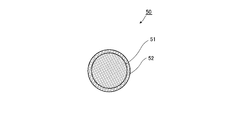
- FIG. 3 is a cross-sectional view perpendicular to the longitudinal direction of the bypass propagation optical fiber 50 of FIG.
- the bypass propagation optical fiber 50 includes a core 51 and a clad 52 that covers the core 51.
- the outer shape of the clad 52 in the cross section is circular.
- the refractive index of the core 51 is equal to the refractive index of the clad 32 of the amplification optical fiber 30 and is higher than the refractive index of the clad 52 of the bypass propagation optical fiber 50.
- Examples of the material constituting the core 51 include the same material as the clad 32 of the amplification optical fiber 30 described above.
- the bypass propagation optical fiber 50 has a loop structure that is continuous as a non-end state in the longitudinal direction, and a part thereof is integrated with an intermediate portion of the amplification optical fiber 30.
- the optical coupling portion 61 is formed.
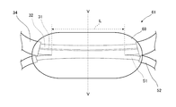
- FIG. 4 is an enlarged view of the optical coupling portion 61 of FIG. 1
- FIG. 5 is a cross-sectional view taken along the line VV of FIG.
- the cladding 52 of the bypass propagation optical fiber 50, the outer cladding 33 and the coating layer 34 of the amplification optical fiber 30 are peeled off, and the bypass propagation optical fiber is peeled off.
- 50 cores 51 and the clad 32 of the amplification optical fiber 30 are exposed.
- the length L of the exposed portion is selected in the range of several mm to several tens mm, for example. However, it may be outside this range.
- the exposed portions of both the core 51 and the clad 32 are covered with a resin 69.
- the refractive index of the resin 69 is lower than the refractive index of the clad 32, and examples of such a resin 69 include the same resin as that of the outer clad 33.
- seed light as amplified light is emitted from the seed light source 10 and excitation light is emitted from the excitation light source 20.
- the wavelength of the seed light is, for example, 1070 nm
- the wavelength of the excitation light is, for example, 915 nm.
- the seed light emitted from the seed light source 10 is incident on the combiner 40 via the seed light fiber 15, and is incident on the core 31 from one end 36 of the amplification optical fiber 30 by the combiner 40 and propagates through the core 31.
- the pumping light emitted from each pumping light source 20 is incident on the combiner 40 via the pumping light fiber 22, and is incident on the cladding 32 from one end 36 of the amplification optical fiber 30 by the combiner 40 and propagates through the cladding 32. .
- an optical coupling portion 61 in which a part of the core 51 of the bypass propagation optical fiber 50 is optically coupled is formed at the intermediate portion of the clad 32. Due to this coupling, the light propagation condition of the clad 32 in the optical coupling part 61 is different from the light propagation condition in the clad 32 other than the optical coupling part 61.
- the optical coupling portion 61 of the present embodiment is one in which the clad 32 and the core 51 are coupled together by fusion, and therefore, the coupling portion is greatly disturbed.
- the light propagation conditions of the clad 32 in the optical coupling portion 61 and the light propagation conditions in the clad 32 other than the optical coupling portion 61 are further increased as compared with the case where the clad 32 and the core 51 are simply brought into contact with each other. It is very different.
- the excitation light propagating through the cladding 32 of the optical coupling portion 61 changes in its propagation mode, and due to this change, the skew light generated between the input end of the cladding 32 and the optical coupling portion 61 is It is improved as excitation light passing through the core 31. As a result, the skew light included in the excitation light propagating through the clad 32 is reduced.
- a part of the pumping light propagating through the clad 32 of the optical coupling portion 61 is incident on the core 51 of the bypass propagation optical fiber 50. Since the bypass propagation optical fiber 50 has a loop structure, the excitation light incident on the core 51 circulates at least once or more and then exits from the optical coupling portion 61 to the output end side of the clad 32. Therefore, the excitation light propagating through the core 51 of the bypass propagation optical fiber 50 passes through the optical coupling portion 61 at least twice at the time of incidence and at the time of emission. As a result, the skew light included in the pumping light passing through the bypass propagation optical fiber 50 is further reduced as compared with the non-passing pumping light.
- the seed light propagating through the core 31 of the amplification optical fiber 30 is amplified by stimulated emission of the active element added to the core 31, and is emitted from the other end 37 of the amplification optical fiber 30 as emitted light.
- the stimulated emission of the active element is caused by excitation light passing through the core 31.
- the core 51 of the bypass propagation optical fiber 50 is integrally bonded to a part of the clad 32 of the amplification optical fiber 30 by fusion.
- the optical coupling portion 61 is formed.
- the light propagation condition of the clad 32 in the optical coupling part 61 and the light propagation condition in the clad 32 other than the optical coupling part 61 are different. Therefore, the propagation mode of the excitation light propagating through the clad 32 of the optical coupling portion 61 changes, and this change reduces the skew light generated before reaching the optical coupling portion 61.
- the optical coupling portion 61 can be formed without bending the amplification optical fiber 30, the intensity distribution of the excitation light in the amplification optical fiber 30 is changed, or the input end of the amplification optical fiber 30 is excited. Loss of pumping light in the amplification optical fiber 30 due to light returning or the like is prevented in advance. Thus, the amplification efficiency in the amplification optical fiber 30 is improved.
- the optical coupling part 61 is formed in an intermediate part. Therefore, compared with the case where the optical coupling portion 61 is formed at the end portion of the amplification optical fiber 30, the pumping light improved to pass through the core 31 while shortening the propagation distance of the skew light with respect to the clad 32. Propagation distance can be increased. In addition to this, the propagation distance of the skew light with respect to the clad 32 and the propagation distance of the excitation light improved so as to pass through the core 31 according to the position of the optical coupling portion 61 to be formed in the amplification optical fiber 30. Can be adjusted.
- the bypass propagation optical fiber 50 that is optically coupled to the intermediate portion of the amplification optical fiber 30 as the optical coupling portion 61 has a loop structure. For this reason, the excitation light propagating through the core 51 of the bypass propagation optical fiber 50 passes through the optical coupling portion 61 at least twice at the time of incidence and at the time of emission. As a result, the skew light included in the pumping light that passes through the bypass propagation optical fiber 50 is further reduced as compared with the non-passing pumping light. This can be realized without making the outer shape of the cladding 32 of the bypass propagation optical fiber 50 special.
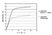
- FIG. 6 shows the results of experiments on the amount of pumping light absorbed according to the length of the amplification optical fiber 30 with and without the optical coupling portion 61.
- the outer diameter of the coating layer 34 in the amplification optical fiber 30 was 650 ⁇ m
- the diameter of the clad 32 was 400 ⁇ m
- Yb was added to the core 31.
- the diameter of the clad 52 of the bypass propagation optical fiber 50 is 250 ⁇ m
- the diameter of the core 51 is 105 ⁇ m.
- the optical coupling portion 61 is formed at a position that is half of the entire length of the amplification optical fiber 30, and the length L of the exposed portion of the core 51 and the exposed portion of the clad 32 in the optical coupling portion 61 is 10 mm.
- the wavelength of the excitation light was 915 nm.
- the skew light is reduced as compared with the case where the optical coupling portion 61 is not formed, and the amount of reduction is significantly larger as the length of the amplification optical fiber is longer. It has been confirmed that
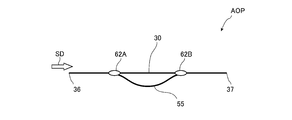
- FIG. 7 is a diagram showing an amplification optical component according to the second embodiment of the present invention
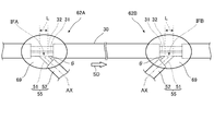
- FIG. 8 is an enlarged view of the optical coupling parts 62A and 62B of FIG.
- the amplification optical component AOP of the present embodiment is provided in place of the amplification optical component AOP of the first embodiment.
- the amplification optical fiber 30 and the bypass propagation optical fiber 55 are the same as those of the first embodiment. And have. As shown in FIG. 7, the bypass propagation optical fiber 55 is different from the bypass propagation optical fiber 50 of the first embodiment having a loop structure in that it has a non-loop structure.
- One end of the bypass propagation optical fiber 55 is formed as an optical coupling portion 62A integrated with an intermediate portion of the amplification optical fiber 30, and the other end of the amplification optical fiber 30 is more than the optical coupling portion 62A. It is formed as an optical coupling part 62B integrated with another intermediate part on the output end side.
- the cladding 32 of the amplification optical fiber 30 in the optical coupling portions 62A and 62B is exposed by peeling off the outer cladding 33 and the coating layer 34, as in the first embodiment.
- the core 51 of the bypass propagation optical fiber 55 in the optical coupling portions 62A and 62B is different from that in the first embodiment.
- the clad 52 at one end is peeled off to expose the core 51
- the clad 52 at the other end is peeled off to expose the core 51.
- Both exposed portions are formed with inclined surfaces IFA and IFB that are inclined with respect to the axis AX of the core 51.
- the inclined surface IFA of the core 51 faces the outer peripheral surface of the exposed portion of the cladding 32, and the propagation direction of the excitation light that propagates the tip of the core 51 through the cladding 32 of the amplification optical fiber 30. At least a part of the exposed portion of the core 51 and the clad 32 is fused in a state of facing the SD. Accordingly, light can propagate from the clad 32 to the core 51 in the optical coupling portion 62A.
- the inclined surface IFB of the core 51 is opposed to the outer peripheral surface of the exposed portion of the cladding 32, and the tip of the core 51 is along the propagation direction SD of the excitation light propagating through the cladding 32. At least a part of the exposed portion of the core 51 and the clad 32 is fused. Accordingly, light can propagate from the core 51 to the clad 32 in the optical coupling portion 62B.
- the inclination angle ⁇ of the inclined surface is not particularly limited, but is preferably a shallow angle with respect to the axis AX of the core 51 from the viewpoint of efficiently transmitting light from the clad 32 to the core 51.
- the exposed portions of the optical coupling portions 62A and 62B are covered with a resin 69 having a lower refractive index than that of the clad 32, as in the first embodiment.
- one end of the core 51 of the bypass propagation optical fiber 55 is integrally bonded to the intermediate portion of the clad 32 of the amplification optical fiber 30 by fusion.
- the optical coupling portion 62A is formed.
- the other end of the core 51 of the bypass propagation optical fiber 55 is integrally bonded to an intermediate portion between the optical coupling portion 62A and the output end of the amplification optical fiber 30, so that the optical coupling portion 62B Is formed.
- the light propagation conditions of the clad 32 in the optical coupling parts 62A and 62B are different from the light propagation conditions in the clad 32 other than the optical coupling parts 62A and 62B, thereby the clad 32 of the optical coupling parts 62A and 62B.
- the propagation mode of the excitation light propagating through changes. Therefore, skew light is reduced in the optical coupling unit 62A, and skew light that cannot be improved by the optical coupling unit 62A and newly generated skew light are reduced in the optical coupling unit 62B.
- the excitation light propagating through the core 51 of the bypass propagation optical fiber 55 is included in the excitation light passing through the bypass propagation optical fiber 55 because it passes through the optical coupling portion 62A when incident and passes through the optical coupling portion 62B when emitted.
- the skew light is further reduced as compared with the non-passing excitation light.
- the optical coupling portions 62A and 62B can be formed without bending the amplification optical fiber 30, the intensity distribution of the excitation light in the amplification optical fiber 30 can be prevented from being changed or lost. Thus, the amplification efficiency in the amplification optical fiber 30 is improved.
- one end of the bypass propagation optical fiber 55 that is optically coupled to the intermediate portion of the amplification optical fiber 30 as the optical coupling portion 62A is fused in a state facing the propagation direction SD of the clad 32.
- the other end of the bypass propagation optical fiber 55 that is optically coupled to the intermediate portion of the amplification optical fiber 30 is in a state along the propagation direction SD of the clad 32, and one end of the optical coupling portion 62 ⁇ / b> B is the end of the clad 32. It is fused in a state along the propagation direction SD.
- Inclined surfaces IFA and IFB that are inclined with respect to the axis AX of the core 51 are formed at one end and the other end of the bypass propagation optical fiber 55 fused to the amplification optical fiber 30, and the inclined surfaces IFA and IFB are formed. Is opposed to the outer periphery of the clad of the bypass propagation optical fiber 55.
- the junction area of one end and the other end of the bypass propagation optical fiber 55 with respect to the clad 32 of the amplification optical fiber 30 increases. Therefore, compared with the case where the inclined surfaces IFA and IFB are not formed, the degree of change in the traveling direction with respect to the excitation light propagating through the clad 32 of the optical coupling portions 62A and 62B can be increased. Skew light is reduced. In addition, the loss of pumping light due to returning to the input end of the amplification optical fiber 30 is further reduced as compared with the case where the inclined surfaces IFA and IFB are not formed. In the case of the amplification optical component AOP of this embodiment, it has been confirmed that the skew light is reduced to the same extent as in the first embodiment.
- FIG. 9 is a diagram showing an amplification optical component according to the third embodiment of the present invention.
- the amplification optical component AOP of this embodiment is provided in place of the amplification optical component AOP of the first embodiment.
- the formation positions of the optical coupling portions 62A and 62B formed at the intermediate position of the amplification optical fiber 30 are different from those of the amplification optical component AOP of the second embodiment.
- the optical coupling portion 62A is formed near the input end of the amplification optical fiber 30, and the optical coupling portion is located near the output end of the amplification optical fiber 30.
- 62B was formed.
- an optical coupling portion 62 ⁇ / b> A is formed near the output end of the amplification optical fiber 30, and near the input end of the amplification optical fiber 30.
- An optical coupling portion 62B is formed.
- the inclined surface IFA of the core 51 faces the outer peripheral surface of the exposed portion of the cladding 32, and the propagation direction of the excitation light in which the tip of the core 51 propagates through the cladding 32 At least a part of the exposed portion of the core 51 and the clad 32 is fused in a state of facing the SD.
- the inclined surface IFB of the core 51 faces the outer peripheral surface of the exposed portion of the cladding 32, and the tip of the core 51 transmits excitation light that propagates through the cladding 32. In a state along the propagation direction SD, at least a part of the exposed portions of the core 51 and the clad 32 are fused.
- one end of the core 51 of the bypass propagation optical fiber 55 is integrally bonded to the intermediate portion of the clad 32 of the amplification optical fiber 30 by fusion.
- the optical coupling portion 62A is formed.
- the other end of the core 51 of the bypass propagation optical fiber 55 is integrally bonded to an intermediate portion between the optical coupling portion 62A and the input end of the amplification optical fiber 30, so that the optical coupling portion 62B is Is formed.
- the light propagation conditions of the clad 32 in the optical coupling parts 62A and 62B are different from the light propagation conditions in the clad 32 other than the optical coupling parts 62A and 62B, thereby the clad 32 of the optical coupling parts 62A and 62B.
- the propagation mode of the excitation light propagating through changes. Therefore, the skew light generated up to the optical coupling unit 62A is reduced.
- the pumping light propagating through the core 51 of the bypass propagation optical fiber 55 passes from the optical coupling portion 62A of the amplification optical fiber 30 through the optical coupling portion 62B that exists on the input end side of the optical coupling portion 62A. Then, the amplification optical fiber 30 is returned from the output end side to the input end side. Therefore, the excitation light propagating through the core 51 of the bypass propagation optical fiber 55 recursively loops between the optical coupling portions 62A and 62B via the amplification optical fiber 30 and passes through the optical coupling portions over a plurality of times.
- FIG. 10 is a diagram showing an amplifying optical component according to the fourth embodiment of the present invention.
- the amplification optical component AOP of the present embodiment is provided in place of the amplification optical component AOP of the first embodiment, and is formed in the amplification optical fiber 30 of the amplification optical component AOP in the first embodiment.
- a plurality of optical coupling portions 61 are provided.
- optical coupling portions 61A to 61C that optically couple with a part of the core 51 of the bypass propagation optical fiber 50 are fixed at the intermediate portion of the clad 32 of the amplification optical fiber 30. It is formed at every interval. However, the interval at which the optical coupling portion 61 should be formed may be an arbitrary interval.
- amplification optical component AOP there are a plurality of opportunities for the propagation mode of pumping light propagating through the cladding 32 of the amplification optical fiber 30 to change until the output end of the amplification optical fiber 30 is reached. become. Therefore, the skew light is further reduced compared to the case of the first embodiment.
- the optical coupling portion 61 is formed at a position 3 m and a position 6 m from the one end 36 of the amplification optical fiber 30 having a total length of 10 m, and the other conditions are the same as in the case shown in FIG.
- the absorption amount of the excitation light measured at 1 was 20 dB.
- the amount of absorption was 15 dB when one optical coupling portion 61 was formed at an intermediate portion of the amplification optical fiber 30 having a total length of 10 m.
- FIG. 11 is a diagram showing an amplification optical component according to the fifth embodiment of the present invention.
- the amplification optical component AOP of the present embodiment is provided in place of the amplification optical component AOP of the first embodiment, and each of the bypass propagation optical fibers of the plurality of optical coupling portions 61A to 61C in the fourth embodiment. 50 is connected to form a single loop structure.
- the detour propagation optical fiber 56 of this embodiment has a loop structure that continues in an endless state in the longitudinal direction.
- the core 51 in the bypass propagation optical fiber 56 and the intermediate portion of the cladding 32 in the amplification optical fiber 30 are exposed at predetermined intervals. Then, at least a part of the exposed portions are fused to form optical coupling portions 61A to 61C in which the exposed portions are coupled together.
- the interval at which the optical coupling portions 61A to 61C should be formed may be an arbitrary interval, and both or one of the exposure interval of the core 51 and the exposure interval of the clad 32 may be an arbitrary interval.
- the opportunity for changing the propagation mode of the excitation light propagating through the cladding 32 of the amplification optical fiber 30 is different from the amplification light.
- the bypass propagation optical fiber 56 optically coupled to the amplification optical fiber 30 has a single loop structure. For this reason, there are a wide variety of propagation paths of pumping light propagating through the core 51 of the bypass propagation optical fiber 56 via the optical coupling portions 61A to 61C.
- the pumping light propagating through the core 51 of the bypass propagation optical fiber 56 is light that is present on the input end side of the optical coupling portion 62C from the optical coupling portion 61C that is closest to the output end of the amplification optical fiber 30.
- the light is returned to the amplification optical fiber 30 through either the coupling portion 61A or 61B.
- the excitation light propagating through the core 51 of the bypass propagation optical fiber 56 recursively loops through various loop paths via any one of the optical coupling portions 61A to 61C, and passes through a plurality of optical coupling portions.
- FIG. 12 is a diagram showing a fiber laser device according to the sixth embodiment of the present invention.
- the fiber laser device 2 of the present embodiment includes an optical fiber amplifier 5, a first resonance fiber 16 connected to the one end 36 side of the amplification optical fiber 30, and the first resonance fiber 16.
- a second FBG 82 as a two-mirror is provided as a main configuration.
- the fiber laser device 2 of the present embodiment is a resonance type fiber laser device.
- the first resonance fiber 16 has the same configuration as the seed light fiber 15 in the first embodiment, and one end is connected to the amplification optical fiber 30 by the combiner 40 in the same manner as the seed light fiber 15. ing. Further, a non-reflection terminal 19 is provided at the other end of the first resonance fiber 16. Further, a first FBG 81 is formed in the core of the first resonance fiber 16. Thus, the first FBG 81 is provided on the one end 36 side of the amplification optical fiber 30. The first FBG 81 has a portion in which the refractive index increases at a constant period along the longitudinal direction of the first resonance fiber 16, and the first FBG 81 is in an excited state by adjusting this period.
- the amplifying optical fiber 30 is configured to reflect at least part of the wavelength of light emitted by the active element. When the active element is Yb as described above, the first FBG 81 has a reflectance of 100% at, for example, 1070 nm.
- the second resonance fiber 17 is connected to the other end 37 of the amplification optical fiber 30.
- the second resonance fiber 17 has the same configuration as the first resonance fiber, and the core of the second resonance fiber 17 is coupled to the core of the amplification optical fiber 30.
- a second FBG 82 is provided in the core of the second resonance fiber 17.
- the second FBG 82 is provided on the other end 37 side of the amplification optical fiber 30.
- the second FBG 82 has a portion where the refractive index increases at a constant period along the longitudinal direction of the second resonance fiber 17, and reflects light having the same wavelength as the light reflected by the first FBG 81 lower than the first FBG 81. For example, light having the same wavelength as the light reflected by the first FBG 81 is reflected at a reflectance of 50%.
- the pumping light when pumping light is emitted from each laser diode 21 of the pumping light source 20, the pumping light enters the clad 32 of the amplification optical fiber 30 in the combiner 40.
- the active element added to the core 31 of the amplification optical fiber 30 is brought into an excited state.
- the active element made into the excited state emits spontaneous emission light of a specific wavelength.
- the spontaneously emitted light at this time is, for example, light having a constant band with a center wavelength of 1070 nm.
- the spontaneous emission light propagates through the core 31 of the amplification optical fiber 30 and is reflected by the first FBG 81 formed in the core of the first resonance fiber 16, and the reflected light is reflected from the amplification optical fiber 30.
- the light propagates to the second FBG 82 formed in the second resonance fiber 17 through the core 31 and is reflected by the second FBG 82, thereby causing light resonance.
- the light is amplified when propagating through the core 31 of the amplification optical fiber 30, and part of the light is transmitted through the second FBG 82 and emitted from the second resonance fiber 17.
- the skew light is reduced in the amplification optical component AOP of the optical fiber amplifier 5 as described above, and the amplification optical fiber 30 efficiently absorbs the excitation light. For this reason, it can be set as the resonance type fiber laser apparatus with high amplification efficiency.
- the first FBG 81 and the second FBG 82 have been described as examples of the first mirror and the second mirror. However, the first mirror and the second mirror are not limited to the FBG. Further, instead of the amplification optical component AOP of the present embodiment, any of the amplification optical components AOP of the second to fifth embodiments may be applied.
- amplification optical components AOP are shown in the first to fifth embodiments, the amplification optical components of the present invention are not limited to those shown as the first to fifth embodiments.
- the amplification optical component AOP shown in FIG. 13 is provided in both the MO-PA type fiber laser device 1 described in the first embodiment and the resonance type fiber laser device 2 described in the sixth embodiment. Applicable.
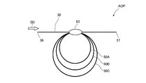
- FIG. 13 is a diagram showing a modification of the amplification optical component.
- an optical coupling portion 63 is formed at an intermediate portion of the amplification optical fiber 30.
- a part of the cores 51 of the three bypass propagation optical fibers 50A to 50C having a loop structure are peeled off, and the exposed portion of each core 51 and the exposed portion of the clad 32 are along each other.
- the exposed portions are fused together, and the exposed portions are optically coupled together.
- each of the bypass propagation optical fibers 50A to 50C has a loop structure, and therefore, the pumping light incident on the core 51 circulates at least once and then enters the optical coupling portion 63. To the output end side of the clad 32. Further, since each of the bypass propagation optical fibers 50A to 50C has a loop structure, there are a wide variety of propagation paths of the excitation light propagating to the bypass propagation optical fibers 50A to 50C via the optical coupling portion 63. Therefore, the number of times the excitation light propagating through the bypass propagation optical fibers 50A to 50C passes through the optical coupling unit 63 increases.
- the skew light included in the pumping light passing through the bypass propagation optical fiber 50 is further reduced.
- the amplification optical component AOP of this modification it has been confirmed that the skew light is reduced to the same extent as in the fourth embodiment.
- the amplification optical component AOP shown as the above modified example or the first to fifth embodiments is merely an example.
- the present invention if the amplification optical fiber 30 and the bypass propagation optical fiber optically coupled to a part of the clad 32 which is the middle in the length direction of the amplification optical fiber 30 are provided, the present invention. It can be applied as an amplification optical component.
- the core 51 of the bypass propagation optical fiber and the clad 32 of the amplification optical fiber 30 are optically coupled by fusion.
- a coupling method other than fusion may be applied.
- the cladding 32 of the optical amplification optical fiber is non-circular, but it may be circular.
- the core 51 of the bypass propagation optical fibers 50, 55, and 56 is circular, but it may be noncircular. Further, the bypass propagation optical fibers 50, 55, and 56 may be replaced with optical amplification optical fibers.
- the optical propagation path optically coupled to the clad 32 of the amplification optical fiber 30 is not the core of the substituted optical amplification optical fiber but the clad.
- the clad of the optical fiber for optical amplification substituted in this way is not limited to a non-circular shape as in the above-described embodiment, and may be a circular shape.
- the fiber laser device in the above embodiment is a forward pump type in which pumping light is incident from one end 36 of the amplification optical fiber 30 and is emitted from the other end 37.
- the fiber laser device in the above embodiment may be of a backward pumping type in which excitation light enters from the other end 37 of the amplification optical fiber 30 and exits from one end 36, and the excitation light is transmitted to one end of the amplification optical fiber 30.
- a dual excitation type in which light enters and exits from both 36 and the other end 37 may be used.
- an optical isolator may be interposed in the propagation path of such a forward-pumped, backward-pumped, or both-pumped fiber laser device.
- amplification optical component AOP shown in the above embodiment or the above modification, and the excitation light source 20 and the combiner 40 in the above embodiment may be used as a part of an optical communication amplification device.
- an amplification optical component capable of improving the amplification efficiency of pumping light in the amplification optical fiber with a simple configuration, an optical fiber amplifier using the same, and a fiber laser An apparatus is provided.
Landscapes
- Physics & Mathematics (AREA)
- Electromagnetism (AREA)
- Engineering & Computer Science (AREA)
- Plasma & Fusion (AREA)
- Optics & Photonics (AREA)
- Lasers (AREA)
Abstract
増幅用光学部品、及び、これを用いた光ファイバ増幅器、並びに、ファイバレーザ装置を提供することを目的とする。 本発明の増幅用光学部品AOPは、活性元素が添加されるコア31、及び、前記活性元素を励起するための励起光が入射されるクラッド32を含む増幅用光ファイバ30と、前記増幅用光ファイバ30の一端36と他端37との間のクラッド部分61に対して光学的に結合され、クラッド32を伝播する励起光の一部を往来させる迂回伝播用光ファイバ50とを備える。
Description
本発明は、増幅用光ファイバを用いて、簡易な構成で励起光を効率的に吸収することができる増幅用光学部品、及び、これを用いた光ファイバ増幅器、並びに、ファイバレーザ装置に関する。
増幅用光ファイバを用いたファイバレーザ装置は、集光性に優れ、パワー密度が高い小さなビームスポットが得られ、更に、非接触加工が可能であることから、レーザ加工分野、医療分野などの様々な分野で用いられている。特に、加工分野や医療分野で用いられるファイバレーザ装置は、高出力化となっている。
ファイバレーザ装置に用いられる増幅用光ファイバは、活性元素が添加されたコアと、コアの外周面を覆うクラッドとを備えている。このクラッドを伝播する励起光が活性元素に吸収された場合、活性元素が励起状態となることで、増幅用光ファイバのコアを伝播する被増幅光が増幅される。従って、活性元素に無駄なく励起光を吸収させることが望ましい。しかし、増幅用光ファイバに入射される励起光には、コアに添加される活性元素に吸収されながら伝播するものと、コアを通過することなく伝播するものとがある。一般に、コアを通過することなく伝播する励起光は、スキュー光と呼ばれている。
このようなスキュー光を抑制する増幅用光ファイバとして、下記特許文献1又は特許文献2が提案されている。特許文献1の増幅用光ファイバでは、励起光が伝播するクラッド(第2コアと記載されている)の断面における外形が四角形にされている。また、特許文献2の増幅用光ファイバでは、増幅ファイバの一部に設けられる圧迫素子によってその一部のクラッドに小さな曲げが形成されている。これら増幅用光ファイバでは、励起光の伝播モードが乱れることでスキュー光が抑制される。
しかし、特許文献1又は特許文献2に記載の増幅用光ファイバは、上記のようにクラッドを特別な形状に形成する必要があり、増幅用光ファイバを製造するための母材作製段階からスキュー光を抑制する特別な設計をする必要がある。また、特許文献2の増幅用光ファイバでは、圧迫素子の圧迫方向などに応じて、増幅用光ファイバの入力端に励起光が戻ることで励起光の損失が生じ、かえって、増幅用光ファイバでの励起光の増幅効率が低下してしまう。このため、増幅用光ファイバを用いて効率よく増幅可能な簡易な構成の増幅用光学部品が望まれている。
そこで、本発明は、増幅用光ファイバでの励起光の増幅効率を簡易な構成で向上し得る増幅用光学部品、及び、これを用いた光ファイバ増幅器、並びに、ファイバレーザ装置を提供することを目的とする。
本発明の増幅用光学部品は、活性元素が添加されるコア、及び、前記活性元素を励起するための励起光が入射されるクラッドを含む増幅用光ファイバと、前記増幅用光ファイバの一端と他端との間のクラッド部分に対して光学的に結合され、前記クラッドを伝播する励起光の一部を往来させる迂回伝播用光ファイバとを備えることを特徴とするものである。
この増幅用光学部品では、増幅用光ファイバのクラッド部分と、迂回伝播用光ファイバの光伝播路とが光学的に結合されているため、増幅用光ファイバのクラッドにおける光伝播条件は、光学的に結合されている部分と、それ以外の部分とで相違する。したがって、光結合部分では、クラッドを伝播するスキュー光の伝播モードに変化が生じ、この変化によって、クラッドを伝播するスキュー光が、コアを通過するものとして改善され低減することになる。また、光結合部分は、増幅用光ファイバの中間部位に形成されているため、増幅用光ファイバの端部に形成する場合に比べて、クラッドに対するスキュー光の伝播距離を短くしつつも、コアを通過するよう改善された励起光の伝播距離を長くすることができる。したがって、コアに対する励起光の通過効率が高められる。これに加えて、増幅用光ファイバを曲げることなく光結合部分が形成可能であるため、増幅用光ファイバでの励起光の強度分布の変移や、増幅用光ファイバの入力端に励起光が戻ることなどに起因する励起光の損失が大幅に抑制可能である。こうして、増幅用光ファイバでの励起光の増幅効率が向上される。一方、迂回伝播用光ファイバは、一般に用いられる光ファイバでも良いので、増幅用光ファイバに対する特別な設計をその母材作成段階から要することなく、増幅用光学部品が簡易に構成可能である。
なお、本明細書において、「光学的に結合」とは、光が伝播可能な状態にあることを意味する。
また、前記迂回伝播用光ファイバは、長手方向へ非端状態として連なるループ構造とされ、前記迂回伝播用光ファイバの一部は、前記クラッド部分の長手方向に沿う状態で、そのクラッド部分に対して光学的に結合されることが好ましい。
このようにすれば、迂回伝播用光ファイバを経由する励起光は、増幅用光ファイバから光結合部分を介して迂回伝播用光ファイバに入射するときと、迂回伝播用光ファイバから光結合部分を介して増幅用光ファイバに出射するときの少なくとも2回にわたって、光結合部分を通る。したがって、このような増幅用光学部品によれば、スキュー光の低減効率がより一段と向上される。
或いは、前記迂回伝播用光ファイバの一端は、前記クラッドを伝播する励起光の伝播方向に対向する状態で、前記クラッド部分に対して光学的に結合され、前記迂回伝播用光ファイバの他端は、前記クラッドを伝播する励起光の伝播方向に沿う状態で、前記迂回伝播用光ファイバの一端が結合されるクラッド部分と、前記増幅用光ファイバの出力端との間のクラッド部分に対して光学的に結合されることが好ましい。
このようにすれば、迂回伝播用光ファイバの一端側の光結合部分においてスキュー光が低減され、他端側の光結合部分において、一端側の光結合部分において改善できなかったスキュー光や、新たに生じたスキュー光が低減される。したがって、このような増幅用光学部品によれば、低減効率がより一段と向上される。
或いは、前記迂回伝播用光ファイバの一端は、前記クラッドを伝播する励起光の伝播方向に対向する状態で、前記クラッド部分に対して光学的に結合され、前記迂回伝播用光ファイバの他端は、前記迂回伝播用光ファイバの一端が結合されるクラッド部分と、前記増幅用光ファイバの入力端との間のクラッド部分に対して光学的に結合されることが好ましい。
このようにすれば、迂回伝播用光ファイバを伝播する励起光は、迂回伝播用光ファイバの一端側の光結合部分から、その光結合部分よりも増幅用光ファイバの入力端寄りとなる他端側の光結合部分に戻されることになる。このため、迂回伝播用光ファイバを伝播する励起光は、一端と他端との間を増幅用光ファイバを介して回帰的にループし、複数にわたって光結合部分を通る。したがって、このような増幅用光学部品によれば、スキュー光の低減効率がより一段と向上される。
また、前記ループ構造とされる迂回伝播用光ファイバを複数有し、各前記迂回伝播用光ファイバの一部は、前記増幅用光ファイバの一端と他端との間において互いに異なる複数のクラッド部分に対して、当該クラッド部分の長手方向に沿う状態で光学的に結合されることが好ましい。
このようにすれば、増幅用光ファイバのクラッドに対して迂回伝播用光ファイバの光結合部分が複数存在することになるため、そのクラッドを伝播する励起光の伝播モードが変化する機会が、光結合部分を単一とする場合に比べて増加することになる。したがって、このような増幅用光学部品によれば、光結合部分を単一とする場合に比べて、より一段とスキュー光が低減される。
また、前記ループ構造とされる迂回伝播用光ファイバにおける複数の部分が、前記増幅用光ファイバの一端と他端との間において互いに異なる複数のクラッド部分に対して、当該クラッド部分の長手方向に沿う状態で光学的に結合されることが好ましい。
このようにすれば、増幅用光ファイバのクラッドに対して迂回伝播用光ファイバの光結合部分が複数存在することになる。これに加えて、迂回伝播用光ファイバがループ構造であるため、迂回伝播用光ファイバを伝播する励起光は、複数の光結合部分のいずれかを介して様々なループ経路で回帰的にループし、複数にわたって光結合部分を通ることになる。したがって、このような増幅用光学部品によれば、光結合部分を単一とする場合に比べて、より一段とスキュー光が低減される。
また、前記迂回伝播用光ファイバの一端と、前記迂回伝播用光ファイバの他端とには、前記迂回伝播用光ファイバの軸に対して斜めとなる傾斜面が形成され、前記傾斜面が前記クラッド部分の外周面に対向されることが好ましい。
このようにすれば、傾斜面が非形成である場合に比べて、増幅用光ファイバのクラッドに対する、光ファイバの一端及び他端の対向面積が増加する。このため、傾斜面が非形成である場合に比べて、光結合部分でのクラッドの光伝播条件と、結合部分以外でのクラッドの光伝播条件とが相違の程度が大きいことにより、光結合部分においてクラッドを伝播する励起光の進行方向がより大きく変化することになる。したがって、このような増幅用光学部品によれば、傾斜面が非形成である場合に比べて、より一段とスキュー光が低減される。
また、前記光学的に結合される部分は、融着により一体として形成されることが好ましい。
このようにすれば、単に当接する場合などに比べて、光結合部分の乱れが大きく生じることにより、光結合部分においてクラッドを伝播する励起光の伝播モードがより大きく変化することになる。したがって、このような増幅用光学部品によれば、単に当接する場合などに比べて、より一段とスキュー光が低減される。
本発明の光ファイバ増幅器は、上記いずれかに記載の増幅用光学部品と、前記クラッドに対して前記励起光を出射する励起光源とを備えることを特徴とするものである。
このような光ファイバ増幅器によれば、増幅用光学部品において、上述のようにスキュー光が低減され、増幅用光ファイバが効率よく励起光を吸収することができるので、同じパワーの励起光源であっても、より高い増幅率とすることができる。
本発明のファイバレーザ装置は、上記のいずれかに記載の増幅用光学部品と、前記クラッドに対して前記励起光を出射する励起光源と、前記コアに対して種光を出射する種光源とを備えることを特徴とするものである。
このようなファイバレーザ装置は、増幅用光学部品において、上述のようにスキュー光が低減され、増幅用光ファイバが効率よく励起光を吸収するとこができるため、種光の増幅効率が高いMO-PA(Master Oscillator - Power Amplifier)型のファイバレーザ装置とすることができる。
或いは、本発明のファイバレーザ装置は、上記のいずれかに記載の増幅用光学部品と、前記クラッドに対して前記励起光を出射する励起光源と、前記増幅用光ファイバの一端側に設けられ、前記活性元素が放出する光の少なくとも一部を反射するミラーと、前記増幅用光ファイバの他端側に設けられ、前記第1ミラーが反射する光を前記第1ミラーよりも低い反射率で反射する第2ミラーとを備えることを特徴とするものである。
このようなファイバレーザ装置は、増幅用光学部品において、上述のようにスキュー光が低減され、増幅用光ファイバが効率よく励起光を吸収するとこができるため、増幅効率が高い共振型のファイバレーザ装置とすることができる。
以上説明したように、本発明によれば、増幅用光ファイバでの励起光の増幅効率を簡易な構成で向上し得る増幅用光学部品、及び、これを用いた光ファイバ増幅器、及び、ファイバレーザ装置が提供される。
以下、本発明の光学部品、及び、これを用いた光ファイバ増幅器、ファイバレーザ装置の好適な実施形態について図面を参照しながら詳細に説明する。
(第1実施形態)
図1は、本発明の第1実施形態に係るファイバレーザ装置を示す式である。
図1は、本発明の第1実施形態に係るファイバレーザ装置を示す式である。
図1に示すように、ファイバレーザ装置1は、例えばMO-PA型のファイバレーザ装置であり、種光を出射する種光源10と、種光を増幅する光ファイバ増幅器5とを備えている。
光ファイバ増幅器5は、励起光を出射する励起光源20と、種光及び励起光が入射される増幅用光学部品AOPと、増幅用光学部品AOPに種光及び励起光を入射するためのコンバイナ40と、を主な構成として備えている。増幅用光学部品AOPは、増幅用光ファイバ30と、増幅用光ファイバ30の中間部位に結合される迂回伝播用光ファイバ50とからなる。
種光源10は、例えば、レーザダイオードから成るレーザ光源や、ファブリペロー型やファイバリング型のファイバレーザ装置から構成されている。この種光源10から出射される種光は、特に制限されるものではないが、例えば、後述のように増幅用光ファイバ30にイッテルビウム(Yb)が添加される場合、波長が1070nmのレーザ光とされる。また、種光源10は、コア、及び、コアを被覆するクラッドから構成される種光用ファイバ15に接続されており、種光源10から出射される種光は、種光用ファイバ15のコアを伝播する。種光用ファイバ15としては、例えば、シングルモードファイバが挙げられ、この場合、種光は種光用ファイバ15をシングルモード光として伝播する。
励起光源20は、複数のレーザダイオード21から構成される。それぞれのレーザダイオード21から出射される励起光は、特に制限されるものではないが、例えば、後述のように増幅用光ファイバ30にYbが添加される場合、波長が915nmのレーザ光とされる。また、励起光源20のそれぞれのレーザダイオード21は、励起光用ファイバ22に接続されており、レーザダイオード21から出射される励起光は、励起光用ファイバ22を伝播する。励起光用ファイバ22としては、例えば、マルチモードファイバが挙げられ、この場合、励起光は励起光用ファイバ22をマルチモード光として伝播する。
図2は、図1の増幅用光ファイバ30の長手方向に垂直となる断面図である。図2に示すように、増幅用光ファイバ30は、コア31と、コア31を被覆するクラッド32と、クラッド32を被覆する外部クラッド33と、外部クラッド33を被覆する被覆層34とから構成される。また、本実施形態では、コア31、外部クラッド33、及び、被覆層34の断面における外形は円形とされ、クラッド32の断面における外形は非円形とされている。なお、本実施の形態では、クラッド32の断面における外形は略正多角形とされる。
クラッド32の屈折率はコア31の屈折率よりも低く、外部クラッド33の屈折率はクラッド32の屈折率よりもさらに低くされている。このような、コア31を構成する材料としては、例えば、屈折率を上昇させるゲルマニウム(Ge)等の元素、及び、励起光源20から出射される励起光により励起されるYb等の活性元素が添加された石英が挙げられる。活性元素としては、希土類元素が挙げられ、希土類元素としては、上記Ybの他にツリウム(Tm)、セリウム(Ce)、ネオジウム(Nd)、ユーロピウム(Eu)、エルビウム(Er)等が挙げられる。さらに活性元素として、希土類元素の他に、ビスマス(Bi)等を挙げることができる。また、クラッド32を構成する材料としては、例えば、何らドーパントが添加されていない純粋石英を挙げることができる。なお、コア31の材料に屈折率を上昇させるGe等の元素が添加されない場合、クラッド32の材料には、屈折率を低下させるフッ素(F)等が添加される。一方、外部クラッド33を構成する材料としては例えば樹脂が挙げられ、具体的には、紫外線硬化樹脂が挙げられる。他方、被覆層34を構成する材料としては、例えば、外部クラッド33を構成する樹脂とは異なる紫外線硬化樹脂が挙げられる。
コンバイナ40は、増幅用光ファイバ30の一端36において、種光用ファイバ15及びそれぞれの励起光用ファイバ22と、増幅用光ファイバ30とを接続している。具体的には、コンバイナ40において、種光用ファイバ15のコアが、増幅用光ファイバ30のコア31に端面接続され、さらに、それぞれの励起光用ファイバ22のコアが、クラッド32に端面接続されている。従って、種光源10から出射する種光、及び、励起光源20から出射する励起光は、増幅用光ファイバ30の一端36を入射端として、それぞれ、コア31及びクラッド32に入射する。なお、増幅用光ファイバ30の他端37は、出射端とされている。
図3は、図1の迂回伝播用光ファイバ50の長手方向に垂直となる断面図である。図3に示すように、迂回伝播用光ファイバ50は、コア51と、コア51を被覆するクラッド52とから構成される。このクラッド52の断面における外形は、増幅用光ファイバ30のクラッド32と異なり、円形とされる。
コア51の屈折率は、増幅用光ファイバ30のクラッド32の屈折率と同等とされ、迂回伝播用光ファイバ50のクラッド52の屈折率よりも高くされている。このようなコア51を構成する材料として、例えば、上述した増幅用光ファイバ30のクラッド32と同じものを挙げることができる。
また、迂回伝播用光ファイバ50は、図1に示すように、長手方向へ非端状態として連なるループ構造とされており、その一部は、増幅用光ファイバ30の中間部位と一体化された光結合部61として形成されている。
図4は、図1の光結合部61の拡大図であり、図5は、図4のV-V線を通る断面図である。図4、図5に示すように、光結合部61では、迂回伝播用光ファイバ50のクラッド52と、増幅用光ファイバ30の外部クラッド33及び被覆層34とが剥離され、迂回伝播用光ファイバ50のコア51と、増幅用光ファイバ30のクラッド32とが露出している。
これらコア51の露出部分とクラッド32の露出部分とが沿った状態で、これら露出部分の少なくとも一部が融着され、露出部分同士が一体として結合されている。従って、光結合部61では、コア51とクラッド32とを相互に光が伝播可能になっている。この露出部分の長さLは、例えば数mm~数十mmの範囲で選定される。ただし、この範囲外であっても良い。
また、コア51及びクラッド32双方の露出部分は、樹脂69により被覆されている。樹脂69の屈折率は、クラッド32の屈折率よりも低くされ、このような樹脂69としては、例えば、外部クラッド33と同様の樹脂を挙げることができる。
次にファイバレーザ装置1の動作について説明する。
まず、種光源10から被増幅光としての種光が出射されると共に、励起光源20から励起光が出射される。上述のように、種光の波長は、例えば1070nmとされ、励起光の波長は、例えば915nmとされる。
種光源10から出射した種光は、種光用ファイバ15を介してコンバイナ40に入射し、コンバイナ40によって増幅用光ファイバ30の一端36からコア31に入射され、コア31を伝播する。一方、各励起光源20から出射した励起光は、励起光用ファイバ22を介してコンバイナ40に入射し、コンバイナ40によって増幅用光ファイバ30の一端36からクラッド32に入射され、クラッド32を伝播する。
上述したように、クラッド32の中間部位では、迂回伝播用光ファイバ50のコア51の一部が光学的に結合する光結合部61が形成されている。この結合に起因して、光結合部61でのクラッド32の光伝播条件は、光結合部61以外のクラッド32での光伝播条件と異なっている。特に、本実施形態の光結合部61は、クラッド32とコア51とを融着により一体として結合したものであるため、その結合部分には乱れが大きく生じているものである。したがって、クラッド32とコア51とを単に当接する場合などに比べて、光結合部61でのクラッド32の光伝播条件と、光結合部61以外のクラッド32での光伝播条件とは、より一段と大きく異なっている。
このため、光結合部61のクラッド32を伝播する励起光はその伝播モードが変化し、この変化に起因して、クラッド32の入力端から光結合部61までの間に発生したスキュー光が、コア31を通過する励起光として改善される。この結果、クラッド32を伝播する励起光に含まれるスキュー光は低減することになる。
また、光結合部61のクラッド32を伝播する励起光の一部は迂回伝播用光ファイバ50のコア51に入射する。この迂回伝播用光ファイバ50はループ構造とされているため、コア51に入射した励起光は少なくとも1回以上周回した後に光結合部61からクラッド32の出力端側へ出射する。したがって、迂回伝播用光ファイバ50のコア51を伝播する励起光は、少なくとも入射時と出射時の2回にわたって光結合部61を通る。この結果、迂回伝播用光ファイバ50を経由する励起光に含まれるスキュー光は、非経由の励起光に比べてより一段と低減することになる。
一方、増幅用光ファイバ30のコア31を伝播する種光は、そのコア31に添加されている活性元素の誘導放出により増幅され、出射光として増幅用光ファイバ30の他端37から出射される。なお、活性元素の誘導放出は、コア31を通過する励起光により引き起こされる。
以上説明したように、本実施形態の増幅用光学部品AOPによれば、増幅用光ファイバ30のクラッド32の一部に対して、迂回伝播用光ファイバ50のコア51が融着により一体に結合され、光結合部61が形成されている。このため、光結合部61でのクラッド32の光伝播条件と、光結合部61以外のクラッド32での光伝播条件とが相違することになる。したがって、光結合部61のクラッド32を伝播する励起光の伝播モードが変化し、この変化によって、光結合部61に到達するまでに発生したスキュー光が低減されることになる。これに加えて、増幅用光ファイバ30を曲げることなく光結合部61が形成可能であるため、増幅用光ファイバ30での励起光の強度分布の変移や、増幅用光ファイバ30入力端に励起光が戻ることなどに起因する増幅用光ファイバ30での励起光の損失が未然に防止される。こうして、増幅用光ファイバ30での増幅効率が向上される。
また、光結合部61は、中間部位に形成されている。このため、増幅用光ファイバ30の端部に光結合部61を形成する場合に比べて、クラッド32に対するスキュー光の伝播距離を短くしつつも、コア31を通過するよう改善された励起光の伝播距離を長くすることができる。これに加えて、増幅用光ファイバ30に形成すべき光結合部61の位置に応じて、クラッド32に対する、スキュー光の伝播距離と、コア31を通過するよう改善された励起光の伝播距離との調整が可能となる。
さらに、光結合部61として、増幅用光ファイバ30の中間部位に光結合される迂回伝播用光ファイバ50は、ループ構造とされている。このため、迂回伝播用光ファイバ50のコア51を伝播する励起光は、少なくとも入射時と出射時の2回にわたって光結合部61を通る。この結果、迂回伝播用光ファイバ50を経由する励起光に含まれるスキュー光は、非経由の励起光に比べてより一段と低減される。なお、このことは、迂回伝播用光ファイバ50のクラッド32の外形を特別な形状にすることなく実現可能である。
なお、増幅用光ファイバ30の長さに応じた励起光吸収量を、光結合部61がある場合とない場合とで実験した結果を図6に示す。この実験では、増幅用光ファイバ30における被覆層34の外径が650μmとされ、クラッド32の径が400μmとされ、コア31にはYbが添加された。一方、迂回伝播用光ファイバ50のクラッド52の径が250μmとされ、コア51の径が105μmとされた。また、光結合部61は、増幅用光ファイバ30の全長の半分となる位置に形成され、その光結合部61におけるコア51の露出部分とクラッド32の露出部分との長さLは10mmとされ、励起光の波長は915nmとされた。この図6からも明らかなように、光結合部61を形成した場合には、非形成の場合に比べてスキュー光が低減され、その低減量については増幅用光ファイバ長が長いほど顕著に大きくなることが確認されている。
(第2実施形態)
次に、本発明の第2実施形態について図7及び図8を参照して詳細に説明する。なお、上記実施形態と同一又は同等の構成要素については、同一の参照符号を付して特に説明する場合を除き重複する説明は省略する。図7は、本発明の第2実施形態に係る増幅用光学部品を示す図であり、図8は、図7の光結合部62A,62Bの拡大図である。
次に、本発明の第2実施形態について図7及び図8を参照して詳細に説明する。なお、上記実施形態と同一又は同等の構成要素については、同一の参照符号を付して特に説明する場合を除き重複する説明は省略する。図7は、本発明の第2実施形態に係る増幅用光学部品を示す図であり、図8は、図7の光結合部62A,62Bの拡大図である。
本実施形態の増幅用光学部品AOPは、第1実施形態の増幅用光学部品AOPに代えて備えられるものであり、第1実施形態と同様の増幅用光ファイバ30と、迂回伝播用光ファイバ55とを有している。この迂回伝播用光ファイバ55は、図7に示すように、非ループ構造とされている点で、ループ構造とされた第1実施形態の迂回伝播用光ファイバ50とは異なっている。
また、この迂回伝播用光ファイバ55の一端は、増幅用光ファイバ30の中間部位と一体化された光結合部62Aとして形成され、他端は、光結合部62Aよりも増幅用光ファイバ30の出力端側となる他の中間部位と一体化された光結合部62Bとして形成されている。
図8に示すように、光結合部62A,62Bにおける増幅用光ファイバ30のクラッド32は、第1実施形態と同様に、外部クラッド33及び被覆層34が剥離されて露出している。これに対し、光結合部62A,62Bにおける迂回伝播用光ファイバ55のコア51は、第1実施形態と異なっている。
すなわち、光結合部62Aでは一方の端部のクラッド52が剥離されてコア51が露出し、光結合部62Bでは他方の端部のクラッド52が剥離されてコア51が露出している。これら双方の露出部分にはコア51の軸AXに対して斜めとなる傾斜面IFA,IFBが形成されている。
そして、光結合部62Aでは、コア51の傾斜面IFAがクラッド32の露出部分の外周面に対向し、かつ、コア51の先端が増幅用光ファイバ30のクラッド32を伝播する励起光の伝播方向SDに対向する状態で、コア51及びクラッド32の露出部分の少なくとも一部が融着される。従って、光結合部62Aでは、クラッド32からコア51へ光が伝播可能になっている。
一方、光結合部62Bでは、コア51の傾斜面IFBがクラッド32の露出部分の外周面に対向し、かつ、コア51の先端がクラッド32を伝播する励起光の伝播方向SDに沿う状態で、コア51及びクラッド32の露出部分の少なくとも一部が融着される。従って、光結合部62Bでは、コア51からクラッド32へ光が伝播可能になっている。
なお、傾斜面の傾斜角度θは特に限定されないが、クラッド32からコア51へ効率よく光を伝播する観点では、コア51の軸AXに対して浅い角度であるほうが好ましい。また、光結合部62A,62Bにおける露出部分は、第1実施形態と同様に、クラッド32よりも低い屈折率となる樹脂69により被覆される。
以上のように本実施形態の増幅用光学部品AOPによれば、増幅用光ファイバ30のクラッド32の中間部位に対して、迂回伝播用光ファイバ55のコア51の一端が融着により一体に結合され、光結合部62Aが形成される。また、光結合部62Aと、増幅用光ファイバ30の出力端との中間部位に対して、迂回伝播用光ファイバ55のコア51の他端が融着により一体に結合され、光結合部62Bが形成されている。
このため、光結合部62A,62Bでのクラッド32の光伝播条件と、光結合部62A,62B以外のクラッド32での光伝播条件とが相違し、これにより光結合部62A,62Bのクラッド32を伝播する励起光の伝播モードが変化する。したがって、光結合部62Aにおいてスキュー光が低減され、光結合部62Bにおいて、光結合部62Aで改善できなかったスキュー光や、新たに生じたスキュー光が低減される。なお、迂回伝播用光ファイバ55のコア51を伝播する励起光は、入射時には光結合部62Aを通り出射時には光結合部62Bを通るため、迂回伝播用光ファイバ55を経由する励起光に含まれるスキュー光は、非経由の励起光に比べてより一段と低減される。
これに加えて、増幅用光ファイバ30を曲げることなく光結合部62A,62Bが形成可能であるため、増幅用光ファイバ30での励起光の強度分布の変移や損失が未然に防止される。こうして、増幅用光ファイバ30での増幅効率が向上される。
さらに、光結合部62Aとして、増幅用光ファイバ30の中間部位に光結合される迂回伝播用光ファイバ55の一端は、クラッド32の伝播方向SDに対向する状態で融着されている。また、光結合部62Bとして、増幅用光ファイバ30の中間部位に光結合される迂回伝播用光ファイバ55の他端は、クラッド32の伝播方向SDに沿う状態で、その一端は、クラッド32の伝播方向SDに沿う状態で融着されている。
このため、光結合部62A,62Bでの励起光の逆伝播が低減され、この結果、増幅用光ファイバ30の入力端に戻ることに起因する励起光の損失が低減される。
増幅用光ファイバ30に融着される迂回伝播用光ファイバ55の一端及び他端には、コア51の軸AXに対して斜めとなる傾斜面IFA,IFBが形成され、その傾斜面IFA,IFBが迂回伝播用光ファイバ55のクラッドの外周に対向されている。
このため、増幅用光ファイバ30のクラッド32に対する、迂回伝播用光ファイバ55の一端及び他端の接合面積が増加することになる。したがって、傾斜面IFA,IFBを非形成とする場合に比べて、光結合部62A,62Bのクラッド32を伝播する励起光に対する進行方向の変化の程度を大きくすることができ、この結果、より一段とスキュー光が低減される。これに加えて、傾斜面IFA,IFBを非形成とする場合に比べて、増幅用光ファイバ30の入力端に戻ることに起因する励起光の損失がより一段と低減される。なお、本実施形態の増幅用光学部品AOPの場合にも、第1実施形態と同程度にスキュー光が低減したことが確認されている。
(第3実施形態)
次に、本発明の第3実施形態について図9を参照して詳細に説明する。なお、上記実施形態と同一又は同等の構成要素については、同一の参照符号を付して特に説明する場合を除き重複する説明は省略する。図9は、本発明の第3実施形態に係る増幅用光学部品を示す図である。
次に、本発明の第3実施形態について図9を参照して詳細に説明する。なお、上記実施形態と同一又は同等の構成要素については、同一の参照符号を付して特に説明する場合を除き重複する説明は省略する。図9は、本発明の第3実施形態に係る増幅用光学部品を示す図である。
本実施形態の増幅用光学部品AOPは、第1実施形態の増幅用光学部品AOPに代えて備えられるものである。本実施形態の増幅用光学部品AOPでは、増幅用光ファイバ30の中間位置に形成される光結合部62A,62Bの形成位置が、第2実施形態の増幅用光学部品AOPと異なっている。
すなわち、第2実施形態の増幅用光学部品AOPでは、上述したように、増幅用光ファイバ30の入力端寄りに光結合部62Aが形成され、増幅用光ファイバ30の出力端寄りに光結合部62Bが形成されていた。これに対し、本実施形態の増幅用光学部品AOPでは、図9に示すように、増幅用光ファイバ30の出力端寄りに光結合部62Aが形成され、増幅用光ファイバ30の入力端寄りに光結合部62Bが形成されている。
光結合部62Aでは、第2実施形態と同様に、コア51の傾斜面IFAがクラッド32の露出部分の外周面に対向し、かつ、コア51の先端がクラッド32を伝播する励起光の伝播方向SDに対向する状態で、コア51及びクラッド32の露出部分の少なくとも一部が融着される。一方、光結合部62Bでも、第2実施形態と同様に、コア51の傾斜面IFBがクラッド32の露出部分の外周面に対向し、かつ、コア51の先端がクラッド32を伝播する励起光の伝播方向SDに沿う状態で、コア51及びクラッド32の露出部分の少なくとも一部が融着される。
以上のように本実施形態の増幅用光学部品AOPによれば、増幅用光ファイバ30のクラッド32の中間部位に対して、迂回伝播用光ファイバ55のコア51の一端が融着により一体に結合され、光結合部62Aが形成される。また、光結合部62Aと、増幅用光ファイバ30の入力端との中間部位に対して、迂回伝播用光ファイバ55のコア51の他端が融着により一体に結合され、光結合部62Bが形成されている。
このため、光結合部62A,62Bでのクラッド32の光伝播条件と、光結合部62A,62B以外のクラッド32での光伝播条件とが相違し、これにより光結合部62A,62Bのクラッド32を伝播する励起光の伝播モードが変化する。したがって、光結合部62Aまでに発生したスキュー光が低減される。
なお、迂回伝播用光ファイバ55のコア51を伝播する励起光は、増幅用光ファイバ30の光結合部62Aから、その光結合部62Aよりも入力端側に存在する光結合部62Bを経るため、増幅用光ファイバ30の出力端側から入力端側に戻されることになる。したがって、迂回伝播用光ファイバ55のコア51を伝播する励起光は、光結合部62Aと62Bとの間を増幅用光ファイバ30を介して回帰的にループし、複数にわたって光結合部を通る。この結果、光結合部62Aまでに発生したスキュー光がより一段と低減されるのみならず、光結合部62Bから62Aまでの間で新たに発生したスキュー光も低減される。このことは、迂回伝播用光ファイバ55のクラッド32の外形を特別な形状にすることなく実現可能である。なお、本実施形態の増幅用光学部品AOPの場合にも、第1実施形態と同程度にスキュー光が低減したことが確認されている。
(第4実施形態)
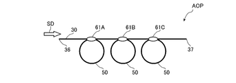
次に、本発明の第4実施形態について図10を参照して詳細に説明する。なお、上記実施形態と同一又は同等の構成要素については、同一の参照符号を付して特に説明する場合を除き重複する説明は省略する。図10は、本発明の第4実施形態に係る増幅用光学部品を示す図である。
次に、本発明の第4実施形態について図10を参照して詳細に説明する。なお、上記実施形態と同一又は同等の構成要素については、同一の参照符号を付して特に説明する場合を除き重複する説明は省略する。図10は、本発明の第4実施形態に係る増幅用光学部品を示す図である。
本実施形態の増幅用光学部品AOPは、第1実施形態の増幅用光学部品AOPに代えて備えられるものであり、第1実施形態における増幅用光学部品AOPの増幅用光ファイバ30に形成される光結合部61を複数有している。
すなわち、図10に示すように、増幅用光ファイバ30のクラッド32の中間部位には、迂回伝播用光ファイバ50のコア51の一部と光学的に結合する光結合部61A~61Cが、一定の間隔ごとに形成されている。ただし、光結合部61を形成すべき間隔が任意の間隔とされていても良い。
このような増幅用光学部品AOPによれば、増幅用光ファイバ30のクラッド32を伝播する励起光の伝播モードが変化する機会が、増幅用光ファイバ30の出力端に至るまでに複数存在することになる。したがって、第1実施形態の場合に比べて、より一段とスキュー光が低減される。
なお、本実施形態の増幅用光学部品AOPの場合、第1実施形態よりも顕著にスキュー光が低減したことが確認されている。具体的には、例えば、全長10mである増幅用光ファイバ30の一端36から3mの位置と6mの位置に光結合部61を形成し、それ以外については、上記図7に示す場合と同一条件で測定された励起光の吸収量は20dBであった。これに対し、全長10mである増幅用光ファイバ30の中間部位に1つの光結合部61を形成した場合の吸収量は、図7に示すように、15dBであった。
(第5実施形態)
次に、本発明の第5実施形態について図11を参照して詳細に説明する。なお、上記実施形態と同一又は同等の構成要素については、同一の参照符号を付して特に説明する場合を除き重複する説明は省略する。図11は、本発明の第5実施形態に係る増幅用光学部品を示す図である。
次に、本発明の第5実施形態について図11を参照して詳細に説明する。なお、上記実施形態と同一又は同等の構成要素については、同一の参照符号を付して特に説明する場合を除き重複する説明は省略する。図11は、本発明の第5実施形態に係る増幅用光学部品を示す図である。
本実施形態の増幅用光学部品AOPは、第1実施形態の増幅用光学部品AOPに代えて備えられるものであり、第4実施形態における複数の光結合部61A~61Cそれぞれの迂回伝播用光ファイバ50を連結して1本のループ構造としたものとなっている。
すなわち、図11に示すように、この実施形態の迂回伝播用光ファイバ56は、長手方向へ非端状態として連なるループ構造とされる。また、迂回伝播用光ファイバ56におけるコア51と、増幅用光ファイバ30におけるクラッド32の中間部位とは所定間隔ごとに露出される。そして、各露出部分同士の少なくとも一部が融着されて、それぞれの露出部分同士が一体に結合された光結合部61A~61Cが形成されている。ただし、光結合部61A~61Cを形成すべき間隔が任意の間隔とされていても良く、コア51の露出間隔とクラッド32の露出間隔の双方又は一方が任意の間隔とされても良い。
以上のように本実施形態の増幅用光学部品AOPによれば、第4実施形態と同様に、増幅用光ファイバ30のクラッド32を伝播する励起光の伝播モードが変化する機会が、増幅用光ファイバ30の出力端に至るまでに複数存在することになる。したがって、第1実施形態の場合に比べて、より一段とスキュー光が低減される。
また、各光結合部61A~61Cとして、増幅用光ファイバ30に光結合される迂回伝播用光ファイバ56は1本のループ構造となっている。このため、各光結合部61A~61Cを介して迂回伝播用光ファイバ56のコア51を伝播する励起光の伝播経路は多岐にわたる。
例えば、迂回伝播用光ファイバ56のコア51を伝播する励起光は、増幅用光ファイバ30の最も出力端側にある光結合部61Cから、その光結合部62Cよりも入力端側に存在する光結合部61A又は61Bのいずれかを経て増幅用光ファイバ30に戻される。したがって、迂回伝播用光ファイバ56のコア51を伝播する励起光は、光結合部61A~61Cのいずれかを介して様々なループ経路で回帰的にループし、複数にわたって光結合部を通る。この結果、光結合部62Aまでに発生したスキュー光がより一段と低減されるのみならず、各光結合部間で新たに発生したスキュー光も低減される。なお、このことは、迂回伝播用光ファイバ56のクラッド32の外形を特別な形状にすることなく実現可能である。なお、本実施形態の増幅用光学部品AOPの場合にも、第4実施形態と同程度以上にスキュー光が低減したことが確認されている。
(第6実施形態)
次に、本発明の第6実施形態について図12を参照して詳細に説明する。なお、第1実施形態と同一又は同等の構成要素については、同一の参照符号を付して特に説明する場合を除き重複する説明は省略する。図12は、本発明の第6実施形態に係るファイバレーザ装置を示す図である。
次に、本発明の第6実施形態について図12を参照して詳細に説明する。なお、第1実施形態と同一又は同等の構成要素については、同一の参照符号を付して特に説明する場合を除き重複する説明は省略する。図12は、本発明の第6実施形態に係るファイバレーザ装置を示す図である。
図12に示すように、本実施形態のファイバレーザ装置2は、光ファイバ増幅器5と、増幅用光ファイバ30の一端36側に接続される第1共振用ファイバ16と、第1共振用ファイバ16に設けられる第1ミラーとしての第1FBG(Fiber Bragg Grating)81と、増幅用光ファイバ30の他端37側に接続される第2共振用ファイバ17と、第2共振用ファイバ17に設けられる第2ミラーとしての第2FBG82とを主な構成として備える。このように、本実施形態のファイバレーザ装置2は、共振型のファイバレーザ装置とされる。
第1共振用ファイバ16は、例えば、第1実施形態における種光用ファイバ15と同様の構成とされ、一端が種光用ファイバ15と同様にして、コンバイナ40で増幅用光ファイバ30に接続されている。また、第1共振用ファイバ16の他端には、無反射終端19が設けられている。さらに、第1共振用ファイバ16のコアには、第1FBG81が形成されている。こうして第1FBG81は、増幅用光ファイバ30の一端36側に設けられている。第1FBG81は、第1共振用ファイバ16の長手方向に沿って一定の周期で屈折率が高くなる部分が繰り返されており、第1FBG81は、この周期が調整されることにより、励起状態とされた増幅用光ファイバ30の活性元素が放出する光の少なくとも一部の波長を反射するように構成されている。第1FBG81は、上述のように活性元素がYbである場合、例えば1070nmにおいて反射率が100%とされる。
また、増幅用光ファイバ30の他端37には、第2共振用ファイバ17が接続されている。第2共振用ファイバ17は、例えば、第1共振用ファイバと同様の構成とされ、第2共振用ファイバ17のコアが増幅用光ファイバ30のコアと結合している。第2共振用ファイバ17のコアには、第2FBG82が設けられている。こうして第2FBG82は、増幅用光ファイバ30の他端37側に設けられている。第2FBG82は、第2共振用ファイバ17の長手方向に沿って一定の周期で屈折率が高くなる部分が繰り返されており、第1FBG81が反射する光と同じ波長の光を第1FBG81よりも低い反射率で反射するように構成され、例えば、第1FBG81が反射する光と同じ波長の光が50%の反射率で反射されるように構成されている。
このようなファイバレーザ装置2においては、励起光源20のそれぞれのレーザダイオード21から励起光が出射されると、この励起光がコンバイナ40において、増幅用光ファイバ30のクラッド32に入射する。そして、第1実施形態と同様にして、増幅用光ファイバ30のコア31に添加されている活性元素を励起状態とする。そして励起状態とされた活性元素は、特定の波長の自然放出光を放出する。このときの自然放出光は、例えば、中心波長が1070nmで一定の帯域を有する光である。この自然放出光は、増幅用光ファイバ30のコア31を伝播して、第1共振用ファイバ16のコアに形成さているいる第1FBG81により反射され、反射された光が、増幅用光ファイバ30のコア31を介して、第2共振用ファイバ17に形成されている第2FBG82まで伝播し、第2FBG82で反射されて、光の共振が生じる。そして、光が、増幅用光ファイバ30のコア31を伝播するときに増幅されて、一部の光が第2FBG82を透過して、第2共振用ファイバ17から出射される。
本実施形態のファイバレーザ装置2によれば、光ファイバ増幅器5の増幅用光学部品AOPにおいて上述のようにスキュー光が低減され、増幅用光ファイバ30が効率よく励起光が吸収される。このため、増幅効率が高い共振型のファイバレーザ装置とすることができる。なお、本実施形態において、第1ミラー、第2ミラーとして、第1FBG81、第2FBG82を例に説明したが、第1ミラー、第2ミラーは、FBGに限定されない。また、本実施形態の増幅用光学部品AOPに代えて、第2~第5実施形態の増幅用光学部品AOPのいずれかが適用されても良い。
以上、本発明について、第1~第6実施形態を例に説明したが、本発明はこれらに限定されるものではない。
例えば、第1~第5実施形態において、それぞれ異なる増幅用光学部品AOPを示したが、本発明の増幅用光学部品は、第1~第5実施形態として示すものに限らない。例えば、図13に示す増幅用光学部品AOPが、第1実施形態で説明したMO-PA型のファイバレーザ装置1、及び、第6実施形態で説明した共振型のファイバレーザ装置2のどちらにも適用可能である。
図13は、増幅用光学部品の変形例を示す図である。図13に示すように、本変形例の増幅用光学部品AOPでは、増幅用光ファイバ30の中間部位に対して光結合部63が形成されている。この光結合部63では、ループ構造でなる3つの迂回伝播用光ファイバ50A~50Cの一部のコア51がそれぞれ剥離され、各コア51の露出部分と、クラッド32の露出部分とが互いに沿った状態で融着され、露出部分同士が一体として光学的に結合されている。本変形例の増幅用光学部品AOPによれば、各迂回伝播用光ファイバ50A~50Cはループ構造とされているため、コア51に入射した励起光は少なくとも1回以上周回した後に光結合部63からクラッド32の出力端側へ出射する。また、各迂回伝播用光ファイバ50A~50Cがそれぞれループ構造となっているため、光結合部63を介して迂回伝播用光ファイバ50A~50Cへ伝播する励起光の伝播経路は多岐にわたる。したがって、光結合部63に対する、迂回伝播用光ファイバ50A~50Cを伝播する励起光の通過回数が多くなる。この結果、迂回伝播用光ファイバ50を経由する励起光に含まれるスキュー光はより一段と低減される。なお、本変形例の増幅用光学部品AOPの場合にも、第4実施形態と同程度にスキュー光が低減したことが確認されている。
あくまで、上記変形例又は第1~第5実施形態として示した増幅用光学部品AOPは例示である。要するに、増幅用光ファイバ30と、増幅用光ファイバ30の長さ方向の中間となるクラッド32の一部に対して光学的に結合される迂回伝播用光ファイバとを備えていれば、本発明の増幅用光学部品として適用できる。
また、上記実施形態、及び、上記変形例に示す増幅用光学部品AOPでは、迂回伝播用光ファイバのコア51と、増幅用光ファイバ30のクラッド32とが、融着により光学的に結合された。しかし、コア51とクラッド32とが光学的に結合されてさえいれば、融着以外の結合手法が適用されていても良い。
また、上記実施形態、及び、上記変形例に示す増幅用光学部品AOPでは、光増幅用光ファイバのクラッド32が非円形とされたが、円形であっても良い。
また、上記実施形態、及び、上記変形例に示す増幅用光学部品AOPでは、迂回伝播用光ファイバ50,55,56のコア51が円形とされたが、非円形であっても良い。また、迂回伝播用光ファイバ50,55,56が、光増幅用光ファイバに代替されていても良い。なお、このように代替する場合、増幅用光ファイバ30のクラッド32と光学的に結合される光伝播路は、代替される光増幅用光ファイバのコアではなくクラッドとなる。また、このように代替される光増幅用光ファイバのクラッドは、上記実施形態のように非円形に限らず、円形としても良い。
また、上記実施形態におけるファイバレーザ装置は、励起光を増幅用光ファイバ30の一端36から入射し他端37から出射する前方励起型とされた。しかしながら、上記実施形態におけるファイバレーザ装置は、励起光を増幅用光ファイバ30の他端37から入射し一端36から出射する後方励起型とされても良く、励起光を増幅用光ファイバ30の一端36及び他端37の双方から入出射する双方励起型とされても良い。なお、このような前方励起型、後方励起型、又は、双方励起型のファイバレーザ装置の伝搬経路には光アイソレータが介在されていても良い。
また、上記実施形態、又は、上記変形例に示す増幅用光学部品AOPと、上記実施形態の励起光源20及びコンバイナ40とが、光通信用増幅装置の一部として用いられても良い。
以上説明したように、本発明によれば、増幅用光ファイバでの励起光の増幅効率を簡易な構成で向上し得る増幅用光学部品、及び、これを用いた光ファイバ増幅器、並びに、ファイバレーザ装置が提供される。
1、2・・・ファイバレーザ装置
5・・・光ファイバ増幅器
10・・・種光源
15・・・種光用ファイバ
16・・・第1共振用ファイバ
17・・・第2共振用ファイバ
19・・・無反射終端
20・・・励起光源
21・・・レーザダイオード
22・・・励起光用ファイバ
30・・・増幅用光ファイバ
31・・・コア
32・・・クラッド
33・・・外部クラッド
34・・・被覆層
40・・・コンバイナ
50、50A~50C、55、56・・・迂回伝播用光ファイバ
61、61A~61C、62A、62B、63・・・光結合部
69・・・樹脂
81・・・第1FBG
82・・・第2FBG
AOP・・・増幅用光学部品
AX・・・軸
IFA,IFB・・・傾斜面
5・・・光ファイバ増幅器
10・・・種光源
15・・・種光用ファイバ
16・・・第1共振用ファイバ
17・・・第2共振用ファイバ
19・・・無反射終端
20・・・励起光源
21・・・レーザダイオード
22・・・励起光用ファイバ
30・・・増幅用光ファイバ
31・・・コア
32・・・クラッド
33・・・外部クラッド
34・・・被覆層
40・・・コンバイナ
50、50A~50C、55、56・・・迂回伝播用光ファイバ
61、61A~61C、62A、62B、63・・・光結合部
69・・・樹脂
81・・・第1FBG
82・・・第2FBG
AOP・・・増幅用光学部品
AX・・・軸
IFA,IFB・・・傾斜面
Claims (11)
- 活性元素が添加されるコア、及び、前記活性元素を励起するための励起光が入射されるクラッドを含む増幅用光ファイバと、
前記増幅用光ファイバの一端と他端との間のクラッド部分に対して光学的に結合され、前記クラッドを伝播する励起光の一部を往来させる迂回伝播用光ファイバと
を備えることを特徴とする増幅用光学部品。 - 前記迂回伝播用光ファイバは、長手方向へ非端状態として連なるループ構造とされ、
前記迂回伝播用光ファイバの一部は、前記クラッド部分の長手方向に沿う状態で、そのクラッド部分に対して光学的に結合される
ことを特徴とする請求項1に記載の増幅用光学部品。 - 前記迂回伝播用光ファイバの一端は、前記クラッドを伝播する励起光の伝播方向に対向する状態で、前記クラッド部分に対して光学的に結合され、
前記迂回伝播用光ファイバの他端は、前記クラッドを伝播する励起光の伝播方向に沿う状態で、前記迂回伝播用光ファイバの一端が結合されるクラッド部分と、前記増幅用光ファイバの出力端との間のクラッド部分に対して光学的に結合される
ことを特徴とする請求項1に記載の増幅用光学部品。 - 前記迂回伝播用光ファイバの一端は、前記クラッドを伝播する励起光の伝播方向に対向する状態で、前記クラッド部分に対して光学的に結合され、
前記迂回伝播用光ファイバの他端は、前記迂回伝播用光ファイバの一端が結合されるクラッド部分と、前記増幅用光ファイバの入力端との間のクラッド部分に対して光学的に結合される
ことを特徴とする請求項1に記載の増幅用光学部品。 - 前記ループ構造とされる迂回伝播用光ファイバを複数有し、
各前記迂回伝播用光ファイバの一部は、前記増幅用光ファイバの一端と他端との間において互いに異なる複数のクラッド部分に対して、当該クラッド部分の長手方向に沿う状態で光学的に結合される
ことを特徴とする請求項2に記載の増幅用光学部品。 - 前記ループ構造とされる迂回伝播用光ファイバにおける複数の部分が、前記増幅用光ファイバの一端と他端との間において互いに異なる複数のクラッド部分に対して、当該クラッド部分の長手方向に沿う状態で光学的に結合される
ことを特徴とする請求項2に記載の増幅用光学部品。 - 前記迂回伝播用光ファイバの一端と、前記迂回伝播用光ファイバの他端とには、前記迂回伝播用光ファイバの軸に対して斜めとなる傾斜面が形成され、
前記傾斜面が前記クラッド部分の外周面に対向される
ことを特徴とする請求項3又は4に記載の増幅用光学部品。 - 前記光学的に結合される部分は、融着により一体として形成される
ことを特徴とする請求項1~7いずれか1項に記載の増幅用光学部品。 - 請求項1~8のいずれか1項に記載の増幅用光学部品と、
前記クラッドに対して前記励起光を出射する励起光源と
を備えることを特徴とする光ファイバ増幅器。 - 請求項1~8のいずれか1項に記載の増幅用光学部品と、
前記クラッドに対して前記励起光を出射する励起光源と、
前記コアに対して種光を出射する種光源と
を備えることを特徴とするファイバレーザ装置。 - 請求項1~8のいずれか1項に記載の増幅用光学部品と、
前記クラッドに対して前記励起光を出射する励起光源と、
前記増幅用光ファイバの一端側に設けられ、前記活性元素が放出する光の少なくとも一部を反射するミラーと、
前記増幅用光ファイバの他端側に設けられ、前記第1ミラーが反射する光を前記第1ミラーよりも低い反射率で反射する第2ミラーと
を備えることを特徴とするファイバレーザ装置。
Applications Claiming Priority (2)
| Application Number | Priority Date | Filing Date | Title |
|---|---|---|---|
| JP2011-074070 | 2011-03-30 | ||
| JP2011074070A JP5202676B2 (ja) | 2011-03-30 | 2011-03-30 | 増幅用光学部品、及び、これを用いた光ファイバ増幅器、並びに、ファイバレーザ装置 |
Publications (1)
| Publication Number | Publication Date |
|---|---|
| WO2012132511A1 true WO2012132511A1 (ja) | 2012-10-04 |
Family
ID=46930279
Family Applications (1)
| Application Number | Title | Priority Date | Filing Date |
|---|---|---|---|
| PCT/JP2012/051328 Ceased WO2012132511A1 (ja) | 2011-03-30 | 2012-01-23 | 増幅用光学部品、及び、これを用いた光ファイバ増幅器、並びに、ファイバレーザ装置 |
Country Status (2)
| Country | Link |
|---|---|
| JP (1) | JP5202676B2 (ja) |
| WO (1) | WO2012132511A1 (ja) |
Families Citing this family (2)
| Publication number | Priority date | Publication date | Assignee | Title |
|---|---|---|---|---|
| JP6998754B2 (ja) * | 2017-12-15 | 2022-01-18 | 古河電気工業株式会社 | 光結合器及び光増幅器 |
| JP7558710B2 (ja) * | 2020-08-17 | 2024-10-01 | 古河電気工業株式会社 | 光結合器、光増幅器及び通信システム |
Citations (7)
| Publication number | Priority date | Publication date | Assignee | Title |
|---|---|---|---|---|
| JPH0325985A (ja) * | 1989-06-23 | 1991-02-04 | Fujitsu Ltd | 光ファイバ増幅器 |
| JPH11136193A (ja) * | 1997-08-23 | 1999-05-21 | Pirelli Cavi & Syst Spa | 光増幅器のマルチモード・ポンピングのためのモード・スクランブリングを有するツイン結合器 |
| WO2000067350A1 (en) * | 1999-04-30 | 2000-11-09 | University Of Southampton | An optical fibre arrangement |
| JP2002237637A (ja) * | 2001-02-08 | 2002-08-23 | Toshiba Corp | ファイバレーザ装置 |
| JP2010028053A (ja) * | 2008-07-24 | 2010-02-04 | Toshiba Corp | ファイバレーザ装置、レーザ加工装置及びレーザ加工方法 |
| WO2010049057A2 (de) * | 2008-10-29 | 2010-05-06 | Trumpf Laser Gmbh + Co. Kg | Optische faseranordnung |
| JP2010212479A (ja) * | 2009-03-11 | 2010-09-24 | Panasonic Corp | ダブルクラッドファイバ及びファイバレーザ装置 |
-
2011
- 2011-03-30 JP JP2011074070A patent/JP5202676B2/ja not_active Expired - Fee Related
-
2012
- 2012-01-23 WO PCT/JP2012/051328 patent/WO2012132511A1/ja not_active Ceased
Patent Citations (7)
| Publication number | Priority date | Publication date | Assignee | Title |
|---|---|---|---|---|
| JPH0325985A (ja) * | 1989-06-23 | 1991-02-04 | Fujitsu Ltd | 光ファイバ増幅器 |
| JPH11136193A (ja) * | 1997-08-23 | 1999-05-21 | Pirelli Cavi & Syst Spa | 光増幅器のマルチモード・ポンピングのためのモード・スクランブリングを有するツイン結合器 |
| WO2000067350A1 (en) * | 1999-04-30 | 2000-11-09 | University Of Southampton | An optical fibre arrangement |
| JP2002237637A (ja) * | 2001-02-08 | 2002-08-23 | Toshiba Corp | ファイバレーザ装置 |
| JP2010028053A (ja) * | 2008-07-24 | 2010-02-04 | Toshiba Corp | ファイバレーザ装置、レーザ加工装置及びレーザ加工方法 |
| WO2010049057A2 (de) * | 2008-10-29 | 2010-05-06 | Trumpf Laser Gmbh + Co. Kg | Optische faseranordnung |
| JP2010212479A (ja) * | 2009-03-11 | 2010-09-24 | Panasonic Corp | ダブルクラッドファイバ及びファイバレーザ装置 |
Also Published As
| Publication number | Publication date |
|---|---|
| JP5202676B2 (ja) | 2013-06-05 |
| JP2012209430A (ja) | 2012-10-25 |
Similar Documents
| Publication | Publication Date | Title |
|---|---|---|
| US8611003B2 (en) | Double clad fiber laser device | |
| JP5680170B1 (ja) | ファイバレーザ装置 | |
| EP1935068B1 (en) | Optical fibre laser | |
| JPWO2011115275A1 (ja) | 光ファイバ増幅器、及び、それを用いたファイバレーザ装置 | |
| JP5771586B2 (ja) | 光ファイバ及びそれを用いたファイバレーザ装置 | |
| JP5980909B2 (ja) | 2μmの範囲で動作する高出力単一モードファイバーレーザーシステム | |
| JP5512348B2 (ja) | 光学部品付き増幅用光ファイバ、及び、これを用いたファイバレーザ装置 | |
| JP5694266B2 (ja) | 光ファイバ及びそれを用いたファイバレーザ装置 | |
| JP5643632B2 (ja) | マルチポートカプラ、及び、それを用いた光ファイバ増幅器及びファイバレーザ装置及び共振器 | |
| JP2015149369A (ja) | ファイバレーザ装置 | |
| JP2001230476A (ja) | 光増幅器 | |
| CN101017952A (zh) | 光纤激光器 | |
| JP5202676B2 (ja) | 増幅用光学部品、及び、これを用いた光ファイバ増幅器、並びに、ファイバレーザ装置 | |
| JP5222970B2 (ja) | 光学部品、及び、これを用いた光ファイバ増幅器、及び、ファイバレーザ装置 | |
| JP2013161875A (ja) | 光学部品、及び、これを用いた光ファイバ増幅器、及び、ファイバレーザ装置 | |
| US11835776B2 (en) | Filter device and laser apparatus | |
| JP2011035012A (ja) | ファイバレーザ装置 | |
| JP2010199563A (ja) | 光増幅器及び共振器 | |
| JP2015179761A (ja) | ファイバレーザ装置 | |
| WO2020203136A1 (ja) | ファイバレーザ装置 | |
| JP5014640B2 (ja) | マルチモードファイバ、光増幅器及びファイバレーザ | |
| JP2019029421A (ja) | ファイバレーザ装置 | |
| JP2010177314A (ja) | ダブルクラッドファイバ、ファイバレーザ装置及び光増幅器 | |
| JP2012212763A (ja) | 光増幅部品、及び、それを用いた光ファイバ増幅器及びファイバレーザ装置 | |
| KR101951349B1 (ko) | 광 공진기 |
Legal Events
| Date | Code | Title | Description |
|---|---|---|---|
| 121 | Ep: the epo has been informed by wipo that ep was designated in this application |
Ref document number: 12765844 Country of ref document: EP Kind code of ref document: A1 |
|
| NENP | Non-entry into the national phase |
Ref country code: DE |
|
| 122 | Ep: pct application non-entry in european phase |
Ref document number: 12765844 Country of ref document: EP Kind code of ref document: A1 |