WO2012132497A1 - 複合材構造体の成形方法 - Google Patents
複合材構造体の成形方法 Download PDFInfo
- Publication number
- WO2012132497A1 WO2012132497A1 PCT/JP2012/050613 JP2012050613W WO2012132497A1 WO 2012132497 A1 WO2012132497 A1 WO 2012132497A1 JP 2012050613 W JP2012050613 W JP 2012050613W WO 2012132497 A1 WO2012132497 A1 WO 2012132497A1
- Authority
- WO
- WIPO (PCT)
- Prior art keywords
- jig
- outer plate
- composite material
- prepreg
- ply
- Prior art date
Links
Images


Classifications
-
- B—PERFORMING OPERATIONS; TRANSPORTING
- B29—WORKING OF PLASTICS; WORKING OF SUBSTANCES IN A PLASTIC STATE IN GENERAL
- B29C—SHAPING OR JOINING OF PLASTICS; SHAPING OF MATERIAL IN A PLASTIC STATE, NOT OTHERWISE PROVIDED FOR; AFTER-TREATMENT OF THE SHAPED PRODUCTS, e.g. REPAIRING
- B29C65/00—Joining or sealing of preformed parts, e.g. welding of plastics materials; Apparatus therefor
- B29C65/02—Joining or sealing of preformed parts, e.g. welding of plastics materials; Apparatus therefor by heating, with or without pressure
-
- B—PERFORMING OPERATIONS; TRANSPORTING
- B29—WORKING OF PLASTICS; WORKING OF SUBSTANCES IN A PLASTIC STATE IN GENERAL
- B29C—SHAPING OR JOINING OF PLASTICS; SHAPING OF MATERIAL IN A PLASTIC STATE, NOT OTHERWISE PROVIDED FOR; AFTER-TREATMENT OF THE SHAPED PRODUCTS, e.g. REPAIRING
- B29C70/00—Shaping composites, i.e. plastics material comprising reinforcements, fillers or preformed parts, e.g. inserts
- B29C70/04—Shaping composites, i.e. plastics material comprising reinforcements, fillers or preformed parts, e.g. inserts comprising reinforcements only, e.g. self-reinforcing plastics
- B29C70/28—Shaping operations therefor
- B29C70/30—Shaping by lay-up, i.e. applying fibres, tape or broadsheet on a mould, former or core; Shaping by spray-up, i.e. spraying of fibres on a mould, former or core
- B29C70/34—Shaping by lay-up, i.e. applying fibres, tape or broadsheet on a mould, former or core; Shaping by spray-up, i.e. spraying of fibres on a mould, former or core and shaping or impregnating by compression, i.e. combined with compressing after the lay-up operation
- B29C70/345—Shaping by lay-up, i.e. applying fibres, tape or broadsheet on a mould, former or core; Shaping by spray-up, i.e. spraying of fibres on a mould, former or core and shaping or impregnating by compression, i.e. combined with compressing after the lay-up operation using matched moulds
-
- B—PERFORMING OPERATIONS; TRANSPORTING
- B29—WORKING OF PLASTICS; WORKING OF SUBSTANCES IN A PLASTIC STATE IN GENERAL
- B29C—SHAPING OR JOINING OF PLASTICS; SHAPING OF MATERIAL IN A PLASTIC STATE, NOT OTHERWISE PROVIDED FOR; AFTER-TREATMENT OF THE SHAPED PRODUCTS, e.g. REPAIRING
- B29C70/00—Shaping composites, i.e. plastics material comprising reinforcements, fillers or preformed parts, e.g. inserts
- B29C70/04—Shaping composites, i.e. plastics material comprising reinforcements, fillers or preformed parts, e.g. inserts comprising reinforcements only, e.g. self-reinforcing plastics
- B29C70/28—Shaping operations therefor
- B29C70/40—Shaping or impregnating by compression not applied
- B29C70/42—Shaping or impregnating by compression not applied for producing articles of definite length, i.e. discrete articles
- B29C70/46—Shaping or impregnating by compression not applied for producing articles of definite length, i.e. discrete articles using matched moulds, e.g. for deforming sheet moulding compounds [SMC] or prepregs
- B29C70/462—Moulding structures having an axis of symmetry or at least one channel, e.g. tubular structures, frames
-
- B—PERFORMING OPERATIONS; TRANSPORTING
- B29—WORKING OF PLASTICS; WORKING OF SUBSTANCES IN A PLASTIC STATE IN GENERAL
- B29C—SHAPING OR JOINING OF PLASTICS; SHAPING OF MATERIAL IN A PLASTIC STATE, NOT OTHERWISE PROVIDED FOR; AFTER-TREATMENT OF THE SHAPED PRODUCTS, e.g. REPAIRING
- B29C43/00—Compression moulding, i.e. applying external pressure to flow the moulding material; Apparatus therefor
- B29C43/02—Compression moulding, i.e. applying external pressure to flow the moulding material; Apparatus therefor of articles of definite length, i.e. discrete articles
- B29C43/18—Compression moulding, i.e. applying external pressure to flow the moulding material; Apparatus therefor of articles of definite length, i.e. discrete articles incorporating preformed parts or layers, e.g. compression moulding around inserts or for coating articles
Definitions
- the present invention relates to a method for forming a composite structure.
- composite structures made of fiber reinforced plastic are widely used as structures having high strength and light weight in aircrafts and windmills.
- FRP Fiber Reinforced Plastics
- Such a composite structure is generally formed by heating and pressing a prepreg in an autoclave.
- a jig is provided on one side of the composite structure, and the shape and dimensions on the side where the jig is not provided vary.
- the outer dimensional accuracy of a hollow object such as an aircraft wing affects the performance, it is necessary to increase the shape accuracy of the bonding surface to a predetermined outer shape and size in the bonding assembly process.
- a pressure bag that can be pressurized and inflated, a sealing mold, and a core material such as a thermoplastic foam material are used, and the hollow object is moved outward from the inside.
- a molding method is used that presses to the side (for example, Patent Document 1 or Patent Document 2).
- This invention is made
- the method for forming a composite structure according to the present invention employs the following means. That is, the method for forming a composite structure according to the first aspect of the present invention includes a winding step of winding a prepreg around an inner mold jig, and a ply laminated on the prepreg wound around the inner mold jig And a forming step of forming a composite outer plate on the outer periphery of the inner mold jig on which the ply is laminated, and mounting and molding the divided outer mold jig. To do.
- the prepreg is wound around the inner mold jig, the ply is laminated on the wound prepreg, and then a composite outer plate is provided and mounted on the outer mold jig to be molded. Therefore, the shape and dimensions of the inner molding surface of the composite structure can be formed by the inner mold jig, and the shape and dimensions of the outer molding surface of the composite structure can be molded by the outer mold jig. Furthermore, by adjusting the thickness of the composite structure by stacking the ply on the prepreg wound around the inner jig and providing the outer plate, the thickness of the composite structure can be easily adjusted. Therefore, it can be set as the composite material structure which improved the shape and dimensional accuracy of the inner side molding surface and the outer side molding surface.
- the method for forming a composite structure according to the second aspect of the present invention includes a winding step of winding a prepreg around an inner jig, and a composite around the outer periphery of the prepreg wound around the inner jig. Forming by attaching a divided outer mold jig to the outer periphery of the inner mold jig in which a ply is laminated on the outer board and a ply is laminated on the outer board. And a molding step.
- the ply was stacked on the outer plate and attached to the outer mold jig for molding. . Therefore, the shape and dimensions of the inner molding surface of the composite structure can be formed by the inner mold jig, and the shape and dimensions of the outer molding surface of the composite structure can be molded by the outer mold jig. Furthermore, by providing the outer plate on the prepreg wound around the inner jig and then stacking and forming the ply, it is easy to adjust the thickness of the composite structure. Therefore, it can be set as the composite material structure which improved the shape and dimensional accuracy of the inner side molding surface and the outer side molding surface.
- the outer plate may be an uncured composite material.
- the outer plate of the uncured composite material is provided on the outer periphery of the ply laminated on the inner die jig, or the outer plate of the uncured composite material is provided on the outer periphery of the prepreg wound around the inner die jig.
- the ply was laminated. Therefore, the thickness of the composite structure can be adjusted by the resin flow of the outer plate when the outer die jig is mounted and molded. Therefore, it is easier to adjust the thickness of the composite structure.
- the prepreg is wound around the inner jig, the ply is laminated on the wound prepreg, and then the composite outer plate is provided and mounted on the outer jig to be molded. Therefore, the shape and dimensions of the inner molding surface of the composite structure can be formed by the inner mold jig, and the shape and dimensions of the outer molding surface of the composite structure can be molded by the outer mold jig. Furthermore, by adjusting the thickness of the composite structure by stacking the ply on the prepreg wound around the inner jig and providing the outer plate, the thickness of the composite structure can be easily adjusted. Therefore, it is possible to mold a composite material structure with improved shape and dimensional accuracy of the inner molding surface and the outer molding surface.
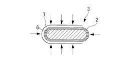
- FIG. 1B is a cross-sectional view taken along the line aa shown in FIG. 1A, showing the tail rotor blade of the helicopter according to the first embodiment of the present invention.
- FIG. 2 is a cross-sectional view showing a spar hardening process of the tail rotor blade shown in FIG. 1. It is the cross-sectional view which showed the modification of the process of the spar hardening shown in FIG.
- FIG. 3 is a cross-sectional view showing the blade hardening process of the tail rotor blade in FIG. 1 or FIG. 2.
- 5 is a flowchart showing a molding process of the tail rotor blade shown in FIGS.
- FIG. 1 shows a schematic configuration diagram of a tail rotor blade 1 of a helicopter.
- the tail rotor blade (composite material structure) 1 is a hollow structure formed by a composite material such as a fiber reinforced plastic (FRP).
- FRP fiber reinforced plastic
- the tail rotor blade 1 incorporates an elastic structural member called a flex beam 11. As shown in FIG. 1B, the tail rotor blade 1 includes a tube-shaped component called a spar 3 provided so as to cover the outer periphery of the flex beam 11, an outer plate 4 that is a composite material, and a honeycomb core 5. It is mainly composed.
- the flex beam 11 has a long axis in the longitudinal direction of the tail rotor blade 1 and is built in the spar 3 so as to hold the tail rotor blade 1.
- the spar 3 is formed into a tube shape by a composite material mainly composed of carbon fiber reinforced plastic (CFRP: Carbon Fiber Reinforced Plastics).
- CFRP Carbon Fiber Reinforced Plastics
- the spar 3 has an elliptical cross-sectional shape perpendicular to the longitudinal direction of the tail rotor blade 1, and the elliptical shape has a long axis in the direction perpendicular to the longitudinal direction of the tail rotor blade 1 (the width direction of the spar 3).
- the spar 3 is divided into a plurality of pieces in the longitudinal direction of the tail rotor blade 1.
- the inner molding surface of the spar 3 is molded into a shape capable of incorporating the flex beam 11 using an inner mold jig (not shown) described later.
- a honeycomb core 5 is provided on the rear edge of the spar 3 (on the right side in FIG. 1B).
- the honeycomb core 5 is provided at the rear edge of the spar 3.
- the honeycomb core 5 has a wedge-shaped cross section as shown in FIG. 1B, which is perpendicular to the longitudinal direction of the tail rotor blade 1.
- the wedge-shaped honeycomb core 5 has a tapered shape from the front edge to the rear edge.
- the outer plate 4 is provided so as to sandwich the honeycomb core 5 and the spar 3 provided on the front edge of the honeycomb core 5.
- a composite material mainly composed of glass fiber reinforced plastic GFRP: Glass Fiber Reinforced Plastic
- the outer plate 4 has an upper surface outer plate 4a and a lower surface outer plate 4b, and is provided such that the spar 3 and the honeycomb core 5 are sandwiched between the upper surface outer plate 4a and the lower surface outer plate 4b. Yes.
- the upper surface outer plate 4a and the lower surface outer plate 4b are formed by using an outer mold jig (not shown) described later so that the spar 3 and the honeycomb core 5 are interposed between the upper surface outer plate 4a and the lower surface outer plate 4b.
- the cross-sectional shape perpendicular to the longitudinal direction of the tail rotor blade 1 is sandwiched so as to be a wing shape.
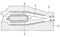
- FIGS. 2 to 4 are cross-sectional views showing the respective steps of forming the tail rotor blade 1 of the present embodiment
- FIG. 5 is a flowchart of the forming steps shown in FIGS. It is shown.
- the prepreg 2 in the winding step of winding the prepreg 2 around the inner mold jig 6, the prepreg 2 is wound around the outer peripheral surface of the inner mold jig 6, and then the prepreg 2 is cured to form the spar 3. Molding is performed (step S1 in FIG. 5).
- the inner jig 6 has an outer circumferential surface having substantially the same shape as the inner molding surface of the molded spar 3.
- the inner jig 6 is made of a material having higher rigidity than a pressure bag, a thermoplastic foam material, or the like conventionally used for forming the inner molding surface of the spar 3.
- an aluminum alloy Invar alloys and composite materials are also used.
- the prepreg 2 is wound around the outer peripheral surface of the inner jig 6 and then wound around the inner jig 6 as in the winding step shown in FIG. 3.
- the spar 3 may be formed by providing an intermediate jig 7 outside the prepreg 2 and curing the prepreg 2.
- the inner jig 6 has the same shape and material as in FIG.
- the middle die 7 has an inner peripheral surface that is substantially the same shape as the outer molding surface of the molded spar 3, and as shown in FIG. 3 is provided on the outer periphery.
- the middle jig 7 is formed of a material having lower rigidity than the inner mold 6 (softer than the inner jig 6).
- the middle jig 7 is removed.
- the surface accuracy of the shape of the outer molding surface of the molded spar 3 is improved as compared with the case of FIG. Can do.
- the plate thickness of the spar 3 formed in the winding process of FIG. 2 or FIG. 3 is measured. Based on the plate thickness measurement result, the number of layers of the adjustment ply (ply) is set. By adjusting the number of layers of the adjustment ply (not shown), the spar 3 has a predetermined plate thickness. Thereby, when the outer plate 4 (see FIG. 4) described later is provided and the tail rotor blade 1 (see FIG. 1) is formed, the tail rotor blade 1 can be adjusted to have a predetermined plate thickness.
- the honeycomb core 5 is provided on the rear edge side of the spar 3 (step S2 in FIG. 5). Further, the set adjustment ply 8 is laminated on the outer periphery of the prepreg 2 wound around the inner die 6 (lamination process). The adjustment ply 8 is provided substantially parallel to the spar 3 from above and below the spar 3.
- the upper surface outer plate 4a and the lower surface outer plate 4b of the composite material are provided on the outer periphery of the inner mold jig 6 and the honeycomb core 5 on which the adjustment ply 8 is stacked so as to sandwich them. Furthermore, an outer jig 9 that can be divided vertically is mounted from outside the upper surface outer plate 4a and the lower surface outer plate 4b. After mounting the inner jig 6, the honeycomb core 5, the upper surface outer plate 4 a, and the lower surface outer plate 4 b on which the adjustment ply 8 is laminated in this manner on the outer die jig 9, these are cured by an autoclave and molded (molding) Step, step S3 in FIG.
- the outer jig 9 that can be divided vertically is removed. Further, the inner jig 6 is pulled out from the inside of the spar 3. Thereby, the molding of the tail rotor blade 1 is completed.
- the following operational effects can be obtained.
- the prepreg 2 is wound around an inner mold jig 6, an adjustment ply 8 is laminated on the wound prepreg 2, and then a composite outer plate 4 is provided and mounted on the outer mold jig 9 to be molded. It was decided. Therefore, the shape and dimensions of the inner molding surface of the spar 3 constituting the tail rotor blade (composite material structure) 1 are formed by the inner die jig 6 and the outer side of the tail rotor blade 1 is formed by the outer die jig 9. The shape and dimensions of the molding surface can be molded.
- the adjustment of the plate thickness of the tail rotor blade 1 is facilitated by forming the outer ply 4 by laminating the adjustment ply 8 on the prepreg 2 wound around the inner jig 6. Therefore, the tail rotor blade 1 with improved shape and dimensional accuracy of the inner molding surface and the outer molding surface can be obtained.
- the adjustment ply 8 is used to adjust the plate thickness of the tail rotor blade 1.
- the present invention is not limited to this, and an adhesive is used instead of the adjustment ply 8. Also good.
- the composite structure formed by the forming method of the present invention is not limited to the tail rotor blade 1 of the helicopter, and can be applied to, for example, an aircraft blade or a windmill blade.
- the molding method of the composite material structure of the present embodiment is different from the first embodiment in that the outer plate is an uncured composite material, and the others are the same. Therefore, the description of the same configuration and process is omitted.
- An uncured composite material is used for the upper surface outer plate (outer plate) and the lower surface outer plate (outer plate) provided so as to sandwich the spar and the honeycomb core.
- An outer die jig that can be divided into upper and lower parts is assembled from the outside of the upper surface outer plate of the uncured composite material and the lower surface outer plate, and is cured by an autoclave.
- the following operational effects can be obtained.
- the upper surface outer plate (outer plate) and the lower surface outer plate (outer plate) of the uncured composite material were provided on the outer periphery of the laminated ply (ply) laminated on the inner jig. Therefore, the thickness of the tail rotor blade (composite structure) can be adjusted by the resin flow of the upper surface outer plate and the lower surface outer plate when the outer die jig is mounted and molded. Therefore, it is easier to adjust the thickness of the tail rotor blade.
- the adjustment ply 8 is described as being laminated on the prepreg 2 wound around the inner jig 6 (see FIG. 1), but the present invention is limited to this. Instead, the outer plate 4 that is a composite material may be provided on the outer periphery of the prepreg 2 wound around the inner jig 6, and then the adjustment ply 8 may be laminated on the outer plate 4.
Landscapes
- Engineering & Computer Science (AREA)
- Mechanical Engineering (AREA)
- Chemical & Material Sciences (AREA)
- Composite Materials (AREA)
- Moulding By Coating Moulds (AREA)
- Casting Or Compression Moulding Of Plastics Or The Like (AREA)
Abstract
複合材構造体の内側の形状、寸法の精度を向上させることが可能な複合材構造体の成形方法を提供することを目的とする。内型治具(6)にプリプレグ(2)を巻回する巻回工程と、内型治具(6)に巻回したプリプレグ(2)にプライ(8)を積層する積層工程と、プライ(8)を積層した内型治具(6)の外周に複合材の外板(4a、4b)を設けて、分割された外型治具(9)を装着して成形する成形工程と、を含むことを特徴とする。
Description
本発明は、複合材構造体の成形方法に関するものである。
例えば、航空機や風車において、高強度かつ軽量化とされた構造体として繊維強化プラスチック(FRP:Fiber Reinforced Plastics)製等の複合材構造体が広く用いられている。このような複合材構造体は、一般的に、プリプレグをオートクレーブにて加熱、加圧することによって成形している。
しかし、プリプレグをオートクレーブにて加熱、加圧して成形する場合には、複合材構造体の片面に治具を設けて成形するため、治具を設けなかった側の形状や寸法にバラつきが生じる。特に、航空機の翼等の中空物体の外周寸法精度は性能を左右するため、接着組立工程において接着面の形状精度を高くして所定の外形形状、寸法にする必要がある。
そこで、中空物体の外形形状、寸法を所定の形状や寸法にするために、加圧膨張可能な加圧袋、密閉金型及び熱可塑性発泡材料等の心材を用い、中空物体の内部から外方へと押し付ける成形法が用いられている(例えば、特許文献1または特許文献2)。
しかし、特許文献1や特許文献2に記載された発明の場合には、加圧袋や熱可塑性発泡材料が低剛性であり、かつ、形状安定性が悪いため、作業性や品質の安定性が問題となる。
また、内型治具を用いて内型治具の外周に積層して、その後、外型治具に移し替える方法もあるが、内型治具と外型治具との2種類の治具が必要となり、製造工程が複雑となる。さらには、高コストかつ品質が安定しにくいという問題がある。
さらに、外型治具のみを用いて成形する場合には、複合材構造体の内側の寸法にバラつきを生じる。そのため、複合材構造体同士を入れ子にして組立てる際には、複合材構造体の内側成形面の形状を補正する作業が必要となる。しかし、アクセス性が悪い場所では、内側成形面の精度を良くするための補正作業が困難であるという問題がある。
本発明は、このような事情に鑑みてなされたものであって、複合材構造体の形状、寸法の精度を向上させることが可能な複合材構造体の成形方法を提供することを目的とする。
上記課題を解決するために、本発明の複合材構造体の成形方法は以下の手段を採用する。
すなわち、本発明の第1の態様にかかる複合材構造体の成形方法は、内型治具にプリプレグを巻回する巻回工程と、前記内型治具に巻回した前記プリプレグにプライを積層する積層工程と、前記プライを積層した前記内型治具の外周に複合材の外板を設けて、分割された外型治具を装着して成形する成形工程と、を含むことを特徴とする。
すなわち、本発明の第1の態様にかかる複合材構造体の成形方法は、内型治具にプリプレグを巻回する巻回工程と、前記内型治具に巻回した前記プリプレグにプライを積層する積層工程と、前記プライを積層した前記内型治具の外周に複合材の外板を設けて、分割された外型治具を装着して成形する成形工程と、を含むことを特徴とする。
プリプレグを内型治具に巻回して、巻回したプリプレグにプライを積層させた後に複合材の外板を設けて外型治具に装着して成形することとした。そのため、内型治具によって複合材構造体の内側成形面の形状や寸法を成形すると共に、外型治具によって複合材構造体の外側成形面の形状や寸法を成形することができる。さらに、内型治具に巻回したプリプレグにプライを積層させて外板を設けて成形することにより、複合材構造体の板厚調整が容易になる。したがって、内側成形面および外側成形面の形状や寸法精度を向上させた複合材構造体とすることができる。
また、本発明の第2の態様にかかる複合材構造体の成形方法は、内型治具にプリプレグを巻回する巻回工程と、前記内型治具に巻回した前記プリプレグの外周に複合材の外板を設けて、該外板にプライを積層する積層工程と、前記外板に前記プライを積層した前記内型治具の外周に、分割された外型治具を装着して成形する成形工程と、を含むことを特徴とする。
プリプレグを内型治具に巻回して、巻回したプリプレグの外周に複合材の外板を設けた後に、その外板にプライを積層して外型治具に装着して成形することとした。そのため、内型治具によって複合材構造体の内側成形面の形状や寸法を成形すると共に、外型治具によって複合材構造体の外側成形面の形状や寸法を成形することができる。さらに、内型治具に巻回したプリプレグに外板を設けた後にプライを積層させて成形することにより、複合材構造体の板厚調整が容易になる。したがって、内側成形面および外側成形面の形状や寸法精度を向上させた複合材構造体とすることができる。
さらに、前記各態様にかかる複合材構造体の成形方法は、前記外板が未硬化複合材であってもよい。
内型治具に積層したプライの外周に未硬化複合材の外板を設けること、または、内型治具に巻回したプリプレグの外周に未硬化複合材の外板を設けた後に外板にプライを積層することとした。そのため、外型治具を装着して成形する際に外板のレジンフローによって、複合材構造体の板厚を調整することができる。したがって、複合材構造体の板厚調整が一層容易となる。
プリプレグを内型治具に巻回して、巻回したプリプレグにプライを積層させた後に複合材の外板を設けて、外型治具に装着して成形することとした。そのため、内型治具によって複合材構造体の内側成形面の形状や寸法を成形すると共に、外型治具によって複合材構造体の外側成形面の形状や寸法を成形することができる。さらに、内型治具に巻回したプリプレグにプライを積層させて外板を設けて成形することにより、複合材構造体の板厚調整が容易になる。したがって、内側成形面および外側成形面の形状や寸法精度を向上させた複合材構造体を成形することができる。
[第1実施形態]
以下、本発明の第1実施形態について、図1から図5を用いて説明する。
図1には、ヘリコプターのテールロータブレード1の概略構成図が示されている。
テールロータブレード(複合材構造体)1は、繊維強化プラスチック(FRP:Fiber Reinforced Plastics)製等の複合材によって成形される中空の構造体である。
以下、本発明の第1実施形態について、図1から図5を用いて説明する。
図1には、ヘリコプターのテールロータブレード1の概略構成図が示されている。
テールロータブレード(複合材構造体)1は、繊維強化プラスチック(FRP:Fiber Reinforced Plastics)製等の複合材によって成形される中空の構造体である。
テールロータブレード1には、フレックスビーム11と呼ばれる弾性構造部材が内蔵されている。テールロータブレード1は、図1Bに示すように、フレックスビーム11の外周を覆うようにして設けられているスパー3と呼ばれるチューブ形状部品と、複合材である外板4と、ハニカムコア5とから主に構成されている。
フレックスビーム11は、テールロータブレード1の長手方向に長軸を有しており、テールロータブレード1を保持するようにスパー3に内蔵されている。
スパー3は、炭素繊維強化プラスチック(CFRP:Carbon Fiber Reinforced Plastics)が主体とされた複合材によってチューブ形状に成形されている。スパー3は、テールロータブレード1の長手方向に直交する断面形状が楕円形状とされており、その楕円形状は、テールロータブレード1の長手方向に直交する方向(スパー3の幅方向)に長軸を有している。
スパー3は、テールロータブレード1の長手方向に複数に分割されて設けられている。スパー3の内側成形面は、フレックスビーム11を内蔵することが可能な形状に、後述する内型治具(図示せず)を用いて成形されている。スパー3の後縁(図1Bにおいて右側)には、ハニカムコア5が設けられている。
ハニカムコア5は、スパー3の後縁に設けられている。ハニカムコア5は、テールロータブレード1の長手方向に直交する断面形状が、図1Bに示すように、楔型形状となっている。楔型のハニカムコア5は、その前縁から後縁にかけて先細りした形状となっている。
外板4は、ハニカムコア5およびハニカムコア5の前縁に設けられているスパー3を挟むように設けられている。外板4には、ガラス繊維強化プラスチック(GFRP:Glass Fiber Reinforced Plastic)が主体とされた複合材が用いられている。外板4は、上面外板4aと下面外板4bとを有しており、これら上面外板4aと下面外板4bとの間にスパー3およびハニカムコア5が挟まれるようにして設けられている。
上面外板4aおよび下面外板4bは、後述する外型治具(図示せず)を用いて成形することによって、スパー3およびハニカムコア5を上面外板4aと下面外板4bとの間に挟んでテールロータブレード1の長手方向に直交する断面形状が翼形状となるように成形する。
次に、このようなテールロータブレード1の成形工程について、図2から図5を用いて説明する。
図2から図4には、本実施形態のテールロータブレード1を成形する各工程を示した横断面図が示されており、図5には、図2から図4に示す成形工程のフローチャートが示されている。
図2から図4には、本実施形態のテールロータブレード1を成形する各工程を示した横断面図が示されており、図5には、図2から図4に示す成形工程のフローチャートが示されている。
図2に示すように、内型治具6にプリプレグ2を巻回する巻回工程では、内型治具6の外周面にプリプレグ2を巻回した後、プリプレグ2を硬化させてスパー3を成形する(図5のステップS1)。ここで、内型治具6は、図2に示すように、成形されたスパー3の内側成形面と略同形状の外周面を有している。この内型治具6には、スパー3の内側成形面を成形するために従来用いられていた加圧袋や熱可塑性発泡材料等よりも剛性が高い材料が用いられており、例えば、アルミ合金や、インバー合金、複合材などが用いられている。
また、図2に示す巻回工程の替わりに、図3に示す巻回工程のように、内型治具6の外周面にプリプレグ2を巻回した後、内型治具6に巻回したプリプレグ2の外側に中型治具7を設けてプリプレグ2を硬化させてスパー3を成形してもよい。
ここで、内型治具6は、図2の場合と同様な形状、かつ、材料が用いられている。中型治具7は、成形されたスパー3の外側成形面と略同形状の内周面を有しており、図3に示すように、スパー3の上方から前縁を経て下方に渡ってスパー3の外周に設けられる。また、中型治具7は、内型治具6よりも剛性が低い(内型治具6よりも柔らかい)材料によって形成されている。
内型治具6よりも剛性が低い中型治具7を用いてスパー3を成形した後、中型治具7を取り除く。このように内型治具6と中型治具7とを用いてスパー3を成形することによって、成形されたスパー3の外側成形面の形状の面精度を図2の場合に比べて向上させることができる。
次に、図2または図3の巻回工程において成形されたスパー3の板厚を計測する。その板厚計測結果に基づいて、調整プライ(プライ)の層数を設定する。この調整プライ(図示せず)の層数を調整することにより、スパー3が所定の板厚とされる。これにより、後述する外板4(図4参照)を設けてテールロータブレード1(図1参照)を成形した際に、テールロータブレード1が所定の板厚になるように調整することができる。
次に、図4に示すように、スパー3の後縁側にハニカムコア5を設ける(図5のステップS2)。さらに、内型治具6に巻回したプリプレグ2の外周に、設定した調整プライ8を積層(積層工程)する。調整プライ8は、スパー3の上下からスパー3に対して略平行に設けられる。
積層工程の後、調整プライ8を積層した内型治具6およびハニカムコア5の外周にそれらを間に挟むようにして複合材の上面外板4aおよび下面外板4bを設ける。さらに、上面外板4aおよび下面外板4bの外側から、上下に分割可能とされている外型治具9を装着する。このように調整プライ8を積層した内型治具6、ハニカムコア5、上面外板4a、下面外板4bを外型治具9に装着後、これらをオートクレーブにて硬化して成形する(成形工程、図5のステップS3)。
オートクレーブによる硬化後、上下に分割可能とされている外型治具9を取り外す。さらに、スパー3の内部から内型治具6を引き抜く。これによって、テールロータブレード1の成形が終了する。
以上の通り、本実施形態に係るテールロータブレード1の成形方法によれば、以下の作用効果を奏する。
プリプレグ2を内型治具6に巻回して、巻回したプリプレグ2に調整プライ(プライ)8を積層させた後に複合材の外板4を設けて外型治具9に装着して成形することとした。そのため、内型治具6によってテールロータブレード(複合材構造体)1を構成しているスパー3の内側成形面の形状や寸法を成形すると共に、外型治具9によってテールロータブレード1の外側成形面の形状や寸法を成形することができる。さらに、内型治具6に巻回したプリプレグ2に調整プライ8を積層させて外板4を設けて成形することにより、テールロータブレード1の板厚調整が容易になる。したがって、内側成形面および外側成形面の形状や寸法精度を向上させたテールロータブレード1とすることができる。
プリプレグ2を内型治具6に巻回して、巻回したプリプレグ2に調整プライ(プライ)8を積層させた後に複合材の外板4を設けて外型治具9に装着して成形することとした。そのため、内型治具6によってテールロータブレード(複合材構造体)1を構成しているスパー3の内側成形面の形状や寸法を成形すると共に、外型治具9によってテールロータブレード1の外側成形面の形状や寸法を成形することができる。さらに、内型治具6に巻回したプリプレグ2に調整プライ8を積層させて外板4を設けて成形することにより、テールロータブレード1の板厚調整が容易になる。したがって、内側成形面および外側成形面の形状や寸法精度を向上させたテールロータブレード1とすることができる。
なお、本実施形態では調整プライ8を用いてテールロータブレード1の板厚を調整するとして説明したが、本発明はこれに限定されるものではなく、調整プライ8の替わりに接着剤を用いても良い。
さらには、本発明の成形方法により成形される複合材構造体は、ヘリコプターのテールロータブレード1に限定されず、例えば、航空機のブレードや風車のブレード等にも適用することができる。
[第2実施形態]
本実施形態の複合材構造体の成形方法は、外板が未硬化複合材である点で、第1実施形態と相違しその他は同様である。したがって、同一の構成および工程については、その説明を省略する。
本実施形態の複合材構造体の成形方法は、外板が未硬化複合材である点で、第1実施形態と相違しその他は同様である。したがって、同一の構成および工程については、その説明を省略する。
スパーおよびハニカムコアを挟むようにして設けられている上面外板(外板)および下面外板(外板)には、未硬化複合材を用いる。未硬化複合材の上面外板)および下面外板の外側から、上下に分割可能とされている外型治具を組み付けてオートクレーブにて硬化する。
以上の通り、本実施形態に係るテールロータブレード(複合材構造体)の成形方法によれば、以下の作用効果を奏する。
未硬化複合材の上面外板(外板)および下面外板(外板)を、内型治具に積層した積層プライ(プライ)の外周に設けることした。そのため、外型治具を装着して成形する際に上面外板および下面外板のレジンフローによって、テールロータブレード(複合材構造体)の板厚を調整することができる。したがって、テールロータブレードの板厚調整が一層容易となる。
未硬化複合材の上面外板(外板)および下面外板(外板)を、内型治具に積層した積層プライ(プライ)の外周に設けることした。そのため、外型治具を装着して成形する際に上面外板および下面外板のレジンフローによって、テールロータブレード(複合材構造体)の板厚を調整することができる。したがって、テールロータブレードの板厚調整が一層容易となる。
また、上記第1実施形態および第2実施形態では、内型治具6(図1参照)に巻回したプリプレグ2に調整プライ8を積層するとして説明したが、本発明はこれに限定されるものではなく、内型治具6に巻回したプリプレグ2の外周に複合材である外板4を設けて、その後、外板4に調整プライ8を積層するとしても良い。
1 複合材構造体(テールロータブレード)
2 プリプレグ
4、4a、4b 外板(上面外板、下面外板)
6 内型治具
8 プライ(調整プライ)
9 外型治具
2 プリプレグ
4、4a、4b 外板(上面外板、下面外板)
6 内型治具
8 プライ(調整プライ)
9 外型治具
Claims (3)
- 内型治具にプリプレグを巻回する巻回工程と、
前記内型治具に巻回した前記プリプレグにプライを積層する積層工程と、
前記プライを積層した前記内型治具の外周に複合材の外板を設けて、分割された外型治具を装着して成形する成形工程と、を含む複合材構造体の成形方法。 - 内型治具にプリプレグを巻回する巻回工程と、
前記内型治具に巻回した前記プリプレグの外周に複合材の外板を設けて、該外板にプライを積層する積層工程と、
前記外板に前記プライを積層した前記内型治具の外周に、分割された外型治具を装着して成形する成形工程と、を含む複合材構造体の成形方法。 - 前記外板が未硬化複合材である請求項1または請求項2に記載の複合材構造体の成形方法。
Priority Applications (2)
| Application Number | Priority Date | Filing Date | Title |
|---|---|---|---|
| US13/876,012 US9833945B2 (en) | 2011-03-28 | 2012-01-13 | Composite material structure forming method |
| EP12763405.3A EP2692511B1 (en) | 2011-03-28 | 2012-01-13 | Forming method for composite material structure |
Applications Claiming Priority (2)
| Application Number | Priority Date | Filing Date | Title |
|---|---|---|---|
| JP2011070605A JP5738033B2 (ja) | 2011-03-28 | 2011-03-28 | 複合材構造体の成形方法 |
| JP2011-070605 | 2011-03-28 |
Publications (1)
| Publication Number | Publication Date |
|---|---|
| WO2012132497A1 true WO2012132497A1 (ja) | 2012-10-04 |
Family
ID=46930265
Family Applications (1)
| Application Number | Title | Priority Date | Filing Date |
|---|---|---|---|
| PCT/JP2012/050613 WO2012132497A1 (ja) | 2011-03-28 | 2012-01-13 | 複合材構造体の成形方法 |
Country Status (4)
| Country | Link |
|---|---|
| US (1) | US9833945B2 (ja) |
| EP (1) | EP2692511B1 (ja) |
| JP (1) | JP5738033B2 (ja) |
| WO (1) | WO2012132497A1 (ja) |
Families Citing this family (3)
| Publication number | Priority date | Publication date | Assignee | Title |
|---|---|---|---|---|
| KR102161158B1 (ko) * | 2018-11-16 | 2020-09-29 | 한국항공우주연구원 | 복합재 샌드위치구조물 제조방법 |
| CN112008990B (zh) * | 2020-08-14 | 2022-03-29 | 威海锦阳电子有限公司 | 线性压缩机磁桶加工方法 |
| CN112297470B (zh) * | 2020-10-10 | 2022-03-29 | 江西洪都航空工业集团有限责任公司 | 一种复材垂直安定面成型模具 |
Citations (7)
| Publication number | Priority date | Publication date | Assignee | Title |
|---|---|---|---|---|
| JPS5016298A (ja) * | 1973-05-30 | 1975-02-20 | ||
| JPS60166593A (ja) * | 1983-10-26 | 1985-08-29 | アグスタ ソチエタ ペル アツィオニ | ヘリコプタプレ−ド用長手部材とその製造方法 |
| US4657615A (en) * | 1984-08-20 | 1987-04-14 | The Boeing Company | Composite leading edge/spar member for an aircraft control surface |
| JPS6324446B2 (ja) | 1981-09-30 | 1988-05-20 | Kawasaki Heavy Ind Ltd | |
| JPH04235004A (ja) * | 1991-01-11 | 1992-08-24 | Kawasaki Heavy Ind Ltd | ロービングプリプレグの積層方法及びその装置 |
| JP3631493B2 (ja) | 1994-08-31 | 2005-03-23 | ユナイテッド テクノロジーズ コーポレイション | ヘリコプタロータブレード用の複合材スパー及びその製造方法 |
| JP2007503533A (ja) * | 2003-08-22 | 2007-02-22 | シコルスキー エアクラフト コーポレイション | ロータブレードの編組翼桁とその製造方法 |
Family Cites Families (5)
| Publication number | Priority date | Publication date | Assignee | Title |
|---|---|---|---|---|
| FR2381662A1 (fr) * | 1977-02-28 | 1978-09-22 | Aerospatiale | Pale, notamment pour un rotor d'helicoptere, et son procede de fabrication |
| US4169749A (en) * | 1977-09-21 | 1979-10-02 | The United States Of America As Represented By The Secretary Of The Navy | Method of making a hollow airfoil |
| GB2040790B (en) * | 1979-02-05 | 1982-10-13 | Westland Aircraft Ltd | Moulding hollow articles |
| US5125993A (en) * | 1991-07-25 | 1992-06-30 | E. I. Du Pont De Nemours And Company | Method for forming and consolidating a fiber reinforced resin structure |
| DE10011879A1 (de) | 2000-03-07 | 2001-09-13 | Roll N Ice Taiwan Corp | Verbundkunststoffstruktur und Verfahren zu deren Herstellung |
-
2011
- 2011-03-28 JP JP2011070605A patent/JP5738033B2/ja active Active
-
2012
- 2012-01-13 EP EP12763405.3A patent/EP2692511B1/en active Active
- 2012-01-13 WO PCT/JP2012/050613 patent/WO2012132497A1/ja active Application Filing
- 2012-01-13 US US13/876,012 patent/US9833945B2/en active Active
Patent Citations (7)
| Publication number | Priority date | Publication date | Assignee | Title |
|---|---|---|---|---|
| JPS5016298A (ja) * | 1973-05-30 | 1975-02-20 | ||
| JPS6324446B2 (ja) | 1981-09-30 | 1988-05-20 | Kawasaki Heavy Ind Ltd | |
| JPS60166593A (ja) * | 1983-10-26 | 1985-08-29 | アグスタ ソチエタ ペル アツィオニ | ヘリコプタプレ−ド用長手部材とその製造方法 |
| US4657615A (en) * | 1984-08-20 | 1987-04-14 | The Boeing Company | Composite leading edge/spar member for an aircraft control surface |
| JPH04235004A (ja) * | 1991-01-11 | 1992-08-24 | Kawasaki Heavy Ind Ltd | ロービングプリプレグの積層方法及びその装置 |
| JP3631493B2 (ja) | 1994-08-31 | 2005-03-23 | ユナイテッド テクノロジーズ コーポレイション | ヘリコプタロータブレード用の複合材スパー及びその製造方法 |
| JP2007503533A (ja) * | 2003-08-22 | 2007-02-22 | シコルスキー エアクラフト コーポレイション | ロータブレードの編組翼桁とその製造方法 |
Non-Patent Citations (1)
| Title |
|---|
| See also references of EP2692511A4 |
Also Published As
| Publication number | Publication date |
|---|---|
| US9833945B2 (en) | 2017-12-05 |
| US20130199709A1 (en) | 2013-08-08 |
| JP2012201093A (ja) | 2012-10-22 |
| EP2692511B1 (en) | 2019-10-16 |
| EP2692511A4 (en) | 2014-12-10 |
| EP2692511A1 (en) | 2014-02-05 |
| JP5738033B2 (ja) | 2015-06-17 |
Similar Documents
| Publication | Publication Date | Title |
|---|---|---|
| KR101786342B1 (ko) | 멀티박스 날개 보 및 표면 | |
| US20210362825A1 (en) | Composite material structure and manufacturing method of composite material structure | |
| US5817269A (en) | Composite fabrication method and tooling to improve part consolidation | |
| US9669581B2 (en) | Method for manufacturing an aeronautical torsion box, torsion box and tool for manufacturing an aeronautical torsion box | |
| AU2016247045B2 (en) | Composite structures with stiffeners and method of making the same | |
| US9573338B2 (en) | Composite sandwich panel with differential resin layers | |
| WO2011004504A1 (ja) | 風車翼及び風車翼の製造方法 | |
| CA2726594C (en) | Aircraft fuselage frame in composite material with stabilized web | |
| KR101864051B1 (ko) | 복합재를 이용한 경량 날개 및 블레이드 제조방법 | |
| CA2685478A1 (en) | Integrated multispar torsion box of composite material | |
| WO2008152103A4 (en) | Method for producing fuselage cell sections for aircraft with composite fibre materials, and a device | |
| EP2070694B1 (en) | Composite panel and method of manufacturing the same | |
| US9051062B1 (en) | Assembly using skeleton structure | |
| US9649820B1 (en) | Assembly using skeleton structure | |
| CN112238551B (zh) | 一种复材机翼多零件一体成型装配模具及成型装配方法 | |
| WO2019021537A1 (ja) | 複合材成形治具及び複合材成形方法 | |
| JP5738033B2 (ja) | 複合材構造体の成形方法 | |
| CN106985413A (zh) | 一种用于泡沫夹芯复合材料结构翼梢小翼的成型工装 | |
| GB2533369A (en) | Method of forming a Laminar composite structure | |
| CN112793185A (zh) | 一种用于t型加筋壁板复合材料的共固化成型方法 | |
| US11383828B2 (en) | Landing gear of rotorcraft | |
| CN114801237A (zh) | 一种全高度包边夹芯复合材料制件的成型方法 | |
| WO2019059260A1 (ja) | 複合材翼の成形方法、複合材翼及び複合材翼の成形型 | |
| CN114889233B (zh) | 一种轻型翼肋及其成型方法 | |
| AU2022266999A1 (en) | Main body of an aerial vehicle |
Legal Events
| Date | Code | Title | Description |
|---|---|---|---|
| 121 | Ep: the epo has been informed by wipo that ep was designated in this application |
Ref document number: 12763405 Country of ref document: EP Kind code of ref document: A1 |
|
| WWE | Wipo information: entry into national phase |
Ref document number: 13876012 Country of ref document: US |
|
| WWE | Wipo information: entry into national phase |
Ref document number: 2012763405 Country of ref document: EP |
|
| NENP | Non-entry into the national phase |
Ref country code: DE |