WO2012132428A1 - 燃料電池モジュール - Google Patents
燃料電池モジュール Download PDFInfo
- Publication number
- WO2012132428A1 WO2012132428A1 PCT/JP2012/002149 JP2012002149W WO2012132428A1 WO 2012132428 A1 WO2012132428 A1 WO 2012132428A1 JP 2012002149 W JP2012002149 W JP 2012002149W WO 2012132428 A1 WO2012132428 A1 WO 2012132428A1
- Authority
- WO
- WIPO (PCT)
- Prior art keywords
- heat
- fuel cell
- heat transfer
- fuel
- cell module
- Prior art date
- Legal status (The legal status is an assumption and is not a legal conclusion. Google has not performed a legal analysis and makes no representation as to the accuracy of the status listed.)
- Ceased
Links
Images



Classifications
-
- H—ELECTRICITY
- H01—ELECTRIC ELEMENTS
- H01M—PROCESSES OR MEANS, e.g. BATTERIES, FOR THE DIRECT CONVERSION OF CHEMICAL ENERGY INTO ELECTRICAL ENERGY
- H01M8/00—Fuel cells; Manufacture thereof
- H01M8/04—Auxiliary arrangements, e.g. for control of pressure or for circulation of fluids
- H01M8/04082—Arrangements for control of reactant parameters, e.g. pressure or concentration
- H01M8/04201—Reactant storage and supply, e.g. means for feeding, pipes
- H01M8/04208—Cartridges, cryogenic media or cryogenic reservoirs
-
- H—ELECTRICITY
- H01—ELECTRIC ELEMENTS
- H01M—PROCESSES OR MEANS, e.g. BATTERIES, FOR THE DIRECT CONVERSION OF CHEMICAL ENERGY INTO ELECTRICAL ENERGY
- H01M8/00—Fuel cells; Manufacture thereof
- H01M8/04—Auxiliary arrangements, e.g. for control of pressure or for circulation of fluids
- H01M8/04007—Auxiliary arrangements, e.g. for control of pressure or for circulation of fluids related to heat exchange
- H01M8/04067—Heat exchange or temperature measuring elements, thermal insulation, e.g. heat pipes, heat pumps, fins
-
- H—ELECTRICITY
- H01—ELECTRIC ELEMENTS
- H01M—PROCESSES OR MEANS, e.g. BATTERIES, FOR THE DIRECT CONVERSION OF CHEMICAL ENERGY INTO ELECTRICAL ENERGY
- H01M2250/00—Fuel cells for particular applications; Specific features of fuel cell system
- H01M2250/30—Fuel cells in portable systems, e.g. mobile phone, laptop
-
- Y—GENERAL TAGGING OF NEW TECHNOLOGICAL DEVELOPMENTS; GENERAL TAGGING OF CROSS-SECTIONAL TECHNOLOGIES SPANNING OVER SEVERAL SECTIONS OF THE IPC; TECHNICAL SUBJECTS COVERED BY FORMER USPC CROSS-REFERENCE ART COLLECTIONS [XRACs] AND DIGESTS
- Y02—TECHNOLOGIES OR APPLICATIONS FOR MITIGATION OR ADAPTATION AGAINST CLIMATE CHANGE
- Y02B—CLIMATE CHANGE MITIGATION TECHNOLOGIES RELATED TO BUILDINGS, e.g. HOUSING, HOUSE APPLIANCES OR RELATED END-USER APPLICATIONS
- Y02B90/00—Enabling technologies or technologies with a potential or indirect contribution to GHG emissions mitigation
- Y02B90/10—Applications of fuel cells in buildings
-
- Y—GENERAL TAGGING OF NEW TECHNOLOGICAL DEVELOPMENTS; GENERAL TAGGING OF CROSS-SECTIONAL TECHNOLOGIES SPANNING OVER SEVERAL SECTIONS OF THE IPC; TECHNICAL SUBJECTS COVERED BY FORMER USPC CROSS-REFERENCE ART COLLECTIONS [XRACs] AND DIGESTS
- Y02—TECHNOLOGIES OR APPLICATIONS FOR MITIGATION OR ADAPTATION AGAINST CLIMATE CHANGE
- Y02E—REDUCTION OF GREENHOUSE GAS [GHG] EMISSIONS, RELATED TO ENERGY GENERATION, TRANSMISSION OR DISTRIBUTION
- Y02E60/00—Enabling technologies; Technologies with a potential or indirect contribution to GHG emissions mitigation
- Y02E60/30—Hydrogen technology
- Y02E60/50—Fuel cells
Definitions
- the present invention relates to a fuel cell module.
- Fuel cells are devices that generate electrical energy from hydrogen and oxygen, and can achieve high power generation efficiency.
- the main characteristics of the fuel cell are direct power generation that does not go through the process of thermal energy and kinetic energy as in the conventional power generation method, so that high power generation efficiency can be expected even on a small scale, and emissions of nitrogen compounds, etc. are low, Noise and vibration are also small, so the environmental performance is good.
- the fuel cell can effectively use the chemical energy of the fuel and has environmentally friendly characteristics, so it is expected as an energy supply system for the 21st century, from space use to automobile use and portable equipment use. It is attracting attention as a promising new power generation system that can be used for various applications from large-scale power generation to small-scale power generation, and technological development is in full swing toward practical application.
- the polymer electrolyte fuel cell is characterized by low operating temperature and high output density compared to other types of fuel cells.
- mobile devices cell phones, notebook personal computers, PDAs, It is expected to be used for power sources such as MP3 players, digital cameras, electronic dictionaries, and electronic books.
- a polymer electrolyte fuel cell for portable devices a planar array type fuel cell in which a plurality of single cells are arranged in a planar shape is known (see Patent Document 1).
- Patent Document 1 In addition to methanol shown in Patent Document 1, the use of hydrogen stored in hydrogen storage alloys and hydrogen cylinders has been studied as a fuel.
- Patent Document 2 discloses a fuel cell incorporating a heat pipe.
- Patent Document 3 discloses a fuel cell using a heat pipe having a structure in which an inert gas is sealed and a cooling effect is exhibited when the temperature exceeds a certain temperature.
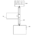
- FIG. 9 schematically shows the problems of these conventional techniques.
- the heat dissipating means 130 and the fuel accommodating portion 60 are disposed on both ends of the heat pipe 50 that is a heat transfer means, and the membrane electrode assembly 12 is disposed on the heat input portion of the heat pipe 50.
- heat is generated from the membrane electrode assembly 12 regardless of the temperature of the membrane electrode assembly 12 (arrow M), so that the power generation performance is not stable when starting the fuel cell whose membrane electrode assembly 12 is at a low temperature.
- the heat flow between the membrane electrode assembly 12 and the fuel storage unit 60 is unidirectional (arrow N), and thus the fuel storage unit 60 cannot be cooled. Therefore, when the heat radiation by the membrane electrode assembly 12 is increased, there is a problem that the temperature of the fuel storage unit 60 is excessively increased.
- the present invention has been made in view of such problems, and an object thereof is to provide a fuel cell module capable of appropriately controlling the temperature of the fuel cell and the fuel storage portion.
- An aspect of the present invention is a fuel cell module.
- the fuel cell module stores a fuel cell including an electrolyte membrane, a cathode provided on one surface of the electrolyte membrane, and an anode provided on the other surface of the electrolyte membrane, and hydrogen supplied to the fuel cell.
- a hydrogen storage alloy for storing the hydrogen storage alloy for storing the hydrogen storage alloy, a hydrogen supply path for supplying hydrogen from the fuel storage unit to the fuel cell, a heat absorption part having heat absorption, a heat dissipation part having heat dissipation, a heat absorption part and heat dissipation And a heat transfer portion having a heat insulating surface provided on the surface of the heat absorption portion, and a heat transfer means thermally connected to the fuel cell and the fuel storage portion in the heat absorption portion.
- the heat transfer means forms a boundary surface between the region having heat transfer properties and the region suppressing heat transfer in the heat transfer section, thereby generating heat generated in the fuel cell.
- the fuel cell When the fuel cell is transmitted to the container and the fuel cell is at a predetermined temperature or higher, a boundary surface between the region having the heat transfer property and the region for suppressing the heat transfer is formed in the heat radiating unit, which is generated in the fuel cell and the fuel container.
- the released heat is released from the heat radiating part to the outside of the fuel cell and the fuel storage part via the heat absorbing part and the heat transfer part.
- the temperature of the fuel storage portion is increased by heat transfer from the membrane electrode assembly.
- the battery module can be activated quickly. Further, during the operation of the fuel cell module, the temperature of the membrane electrode assembly and the fuel storage part can be kept at an appropriate temperature without increasing the temperature more than necessary. Therefore, the temperature of the membrane electrode assembly and the fuel storage portion can be easily adjusted to an appropriate range.
- the heat transfer means is configured such that the heat transfer body that transfers heat is positioned on the heat absorption section side, and the non-heat transfer body that suppresses heat transfer is positioned on the heat dissipation section side.
- It may be a cylindrical heat pipe having a boundary surface formed by a heat element. The boundary surface may move from the heat absorbing portion side toward the heat radiating portion side along the length direction of the heat pipe as the temperature of the heat transfer body increases due to the heat absorbed from the heat absorbing portion.
- a heat pipe heat dissipating member attached to the outer surface of the heat dissipating part may be further provided.
- the boundary surface may move to a position where the plane including the boundary surface crosses at least a part of the heat pipe heat dissipation member.
- the heat absorption part of the heat transfer means is provided between the fuel cell and the fuel storage part, and the heat dissipation part is thermally indirectly connected to the fuel cell and the fuel storage part via the heat absorption part and the heat transfer part. It may be provided at the position.
- the fuel cell is thermally connected adjacent to the fuel storage portion, and the heat absorption portion of the heat transfer means is substantially perpendicular to the contact surface between the fuel cell and the fuel storage portion, and the surface of the fuel cell and the fuel It is thermally connected adjacent to the surface of the housing part, and the heat radiating part is provided at a position indirectly thermally connected to the fuel cell and the fuel housing part via the heat absorbing part and the heat transfer part. Also good.
- the hydrogen supply path may be provided with a path heat dissipation member for releasing heat.
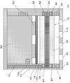
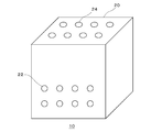
- FIG. 1 is a perspective view showing an external appearance of a fuel cell module according to Embodiment 1.
- FIG. 2 is a cross-sectional view taken along line AA in FIG. 2 is a perspective view showing an external appearance of a structure inside a housing of the fuel cell module according to Embodiment 1.
- FIG. It is the schematic for demonstrating the principle of operation of the heat pipe used for Embodiment 1.
- FIG. FIG. 4 is a cross-sectional view taken along the line BB in FIG. 3 showing the heat flow inside the fuel cell module according to Embodiment 1.
- FIG. 5A is a diagram showing a heat flow when the membrane electrode assembly is below a predetermined temperature.
- FIG. 5B is a diagram showing a heat flow when the membrane electrode assembly is at a predetermined temperature or higher.
- FIG. 6 is a perspective view showing an appearance of a fuel cell module according to Embodiment 2.
- 6 is a perspective view showing an external appearance of a structure inside a housing of a fuel cell module according to Embodiment 2.
- FIG. 9 is a cross-sectional view taken along the line CC of FIG. 7 showing the flow of heat inside the fuel cell module according to Embodiment 2.
- FIG. 8A is a diagram showing the flow of heat when the membrane electrode assembly is below a predetermined temperature.
- FIG. 8B is a diagram showing a heat flow when the membrane electrode assembly is at a predetermined temperature or higher. It is a schematic diagram which shows the heat flow in the fuel cell module of a prior art.
- FIG. 1 is a perspective view showing an appearance of a fuel cell module 10 according to Embodiment 1.
- FIG. 2 is a sectional view taken along line AA in FIG.
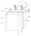
- FIG. 3 is a perspective view showing the appearance of the structure inside the housing 20 of the fuel cell module 10 according to Embodiment 1.
- the fuel cell module 10 includes a housing 20, a membrane electrode assembly 12 housed in the housing 20, a fuel housing portion 60 that is a hydrogen storage alloy tank, and a heat pipe 50 as main components.
- the membrane electrode assembly 12 is a part of the “fuel cell” in this specification or the “fuel cell” itself.
- the housing 20 is provided with a plurality of air intakes 22 on the surface (front surface in FIG. 1, lower portion in FIG. 2) facing the cathode side of the membrane electrode assembly 12. Air as an oxidant can flow into the housing 20 from the outside through the air intake port 22. Moreover, the heat radiation port 24 is provided in the surface (upper surface of FIG. 1) which adjoins the heat pipe heat radiating member 132 shown in FIG. The heat generated inside the fuel cell module 10 can be released to the outside through the heat radiation port 24.
- the membrane electrode assembly 12 includes an electrolyte membrane 30, a cathode catalyst layer 32, and an anode catalyst layer 34.
- the electrolyte membrane 30 preferably exhibits good ion conductivity in a wet state, and functions as an ion exchange membrane that moves protons between the cathode catalyst layer 32 and the anode catalyst layer 34.
- the electrolyte membrane 30 is formed of a solid polymer material such as a fluorine-containing polymer or a non-fluorine polymer, and for example, a sulfonic acid type perfluorocarbon polymer, a polysulfone resin, a perfluorocarbon polymer having a phosphonic acid group or a carboxylic acid group. Etc. can be used.
- sulfonic acid type perfluorocarbon polymer examples include Nafion (manufactured by DuPont: registered trademark) 112.
- non-fluorine polymers include sulfonated aromatic polyetheretherketone and polysulfone.
- the thickness of the electrolyte membrane 30 is, for example, 10 to 200 ⁇ m.
- the cathode catalyst layer 32 is formed on one surface of the electrolyte membrane 30. Air is supplied to the cathode catalyst layer 32 from the outside via the air intake port 22.
- the anode catalyst layer 34 is formed on the other surface of the electrolyte membrane 30. Hydrogen released from the fuel storage unit 60 is supplied to the anode catalyst layer 34.
- a single cell is formed by sandwiching the electrolyte membrane 30 between the pair of cathode catalyst layer 32 and anode catalyst layer 34, and the single cell generates electric power by an electrochemical reaction between hydrogen and oxygen in the air.
- the cathode catalyst layer 32 and the anode catalyst layer 34 have ion exchange resin and catalyst particles, and possibly carbon particles, respectively.
- the ion exchange resin which the cathode catalyst layer 32 and the anode catalyst layer 34 have has a role which connects a catalyst particle and the electrolyte membrane 30, and transmits a proton between both.
- This ion exchange resin may be formed of the same polymer material as the electrolyte membrane 30.
- catalyst metals include Sc, Y, Ti, Zr, V, Nb, Fe, Co, Ni, Ru, Rh, Pd, Pt, Os, Ir, alloys selected from lanthanoid series elements and actinoid series elements, A simple substance is mentioned. When the catalyst is supported, furnace black, acetylene black, ketjen black, carbon nanotubes or the like may be used as the carbon particles.
- the thicknesses of the cathode catalyst layer 32 and the anode catalyst layer 34 are each 10 to 40 ⁇ m, for example.
- the gasket 80 is formed between the electrolyte membrane 30 (the cathode side outer peripheral portion of the electrolyte membrane 30) located around the cathode catalyst layer 32 and the cathode side fixing member 90 provided on the inner peripheral side surface of the casing 20 on the cathode side. Is provided.
- the gasket 80 prevents fuel leakage from the fuel gas chamber 112 to the air chamber 110.
- the gasket 82 is provided between the electrolyte membrane 30 (the outer peripheral portion on the anode side of the electrolyte membrane 30) located around the anode catalyst layer 34 and the anode side fixing member 92 provided on the inner peripheral side surface on the anode side of the housing 20. Is provided.
- the gasket 82 enhances the sealing performance of the fuel gas chamber 112 and suppresses fuel leakage.
- a sheet-like gas seal member 40 is provided so as to face the anode catalyst layer 34.
- a fuel gas chamber 112 serving as a space filled with hydrogen is formed between the gas seal member 40 and the anode catalyst layer 34.
- the gas seal member 40 enhances the sealing performance of the fuel gas chamber 112.
- the gas seal member 40 may be any material that can block outflow of hydrogen and can transmit heat from the membrane electrode assembly 12 to the heat pipe 50.
- a metal plate such as SUS or aluminum is used.
- the gas seal member 40 is a part of the “fuel cell”.
- a heat pipe 50 is disposed between the gas seal member 40 and the fuel storage unit 60.
- the fuel storage unit 60 which is a hydrogen storage alloy tank, is provided on the inner peripheral surface side of the housing 20 facing the anode side of the membrane electrode assembly 12.
- a hydrogen storage alloy capable of storing hydrogen (for example, rare earth-based Mm (Misch metal) Ni 4.32 Mn 0.18 Al 0.1 Fe 0.1 Co 0.3 ) is stored in the fuel storage unit 60.
- the hydrogen storage alloy is not limited to a rare earth system, and may be, for example, a Ti—Mn system, a Ti—Fe system, a Ti—Zr system, a Mg—Ni system, a Zr—Mn system, or the like.
- the hydrogen supply path 70 is provided along the inner peripheral side surface on the anode side of the housing 20, and the hydrogen supply path 70 and the fuel storage section are provided on the side surface of the fuel storage section 60 via the regulator 71.
- the inside of 60 communicates.
- a hydrogen supply port 72 that connects the hydrogen supply path 70 and the fuel gas chamber 112 is provided on the side surface of the fuel gas chamber 112 is provided.
- the control unit 100 controls the output of the fuel cell by adjusting the amount of hydrogen supplied from the fuel storage unit 60 to the fuel gas chamber 112 by controlling the opening of the regulator 71.
- the heat pipe 50 is preferably in contact with the main surface of the gas seal member 40 on the side opposite to the anode catalyst layer 34 and the outer peripheral surface of the fuel storage portion 60 on the anode catalyst layer 34 side. Thereby, the heat transferability between the heat pipe 50, the gas seal member 40, and the fuel storage portion 60 can be enhanced.
- the structure and function of the heat pipe 50 will be described later.
- a heat absorbing portion 124 described later of the heat pipe 50 is provided between the membrane electrode assembly 12 and the fuel storage portion 60 and is thermally connected to both. Further, a heat transfer section 122, a heat radiation section 120, and a gas reservoir section 52, which will be described later, of the heat pipe 50 are disposed on a heat insulating material 62 that is provided at the upper portion of the fuel storage section 60 and does not transmit heat. The body 12 and the fuel storage unit 60 are indirectly connected thermally. A gas reservoir 52 is formed at the end of the second region 78 of the heat pipe 50.
- a plurality of heat pipe heat dissipating members 132 for releasing heat from the heat pipe 50 are provided on the heat dissipating part 120 in the second region 78 of the heat pipe 50.
- the heat pipe heat dissipation member 132 is made of a metal having high heat dissipation efficiency such as aluminum.
- a path heat radiating member 74 for cooling the hydrogen supply path 70 is provided on the upper side of the hydrogen supply path 70 provided on the side surfaces of the membrane electrode assembly 12 and the fuel storage unit 60. . Thereby, it can prevent that the hydrogen supply path 70 becomes too high temperature, and can prevent deterioration of the components of the hydrogen supply path 70. In addition, the sound of the hydrogen supply path 70 can be prevented.
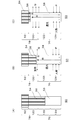
- FIG. 4 is a schematic diagram for explaining the operating principle of the heat pipe 50 used in the first embodiment.
- the heat pipe 50 will be described as a straight pipe.
- FIG. 4A shows the heat pipe 50 in a normal state where no heat is applied.
- the heat pipe 50 has a first region 76 and a second region 78.
- the first region 76 includes, in order from one end side, a heat absorbing portion 124 that can absorb heat from the outside to the inside, and a heat transfer portion 122 that has a heat insulating surface and suppresses heat release. Is formed.
- a heat radiating section 120 capable of releasing heat from the inside to the outside, and a gas reservoir section 52 capable of storing the gas accommodated therein.
- the heat pipe heat dissipating member 132 shown in FIG. 3 is provided on the outer surface of the heat pipe 50 at the heat dissipating part 120.
- a heat transfer body 58 which is a liquid that transfers heat, is enclosed on the heat absorbing portion side of the first region 76 of the heat pipe 50.
- a non-condensable gas 54 that is a non-condensable gas that suppresses heat transfer is enclosed from the second region 78 to the first region 76.
- the heat transfer body 58 and the non-heat transfer body 54 form a boundary surface 56 perpendicular to the length direction of the heat pipe 50. In the stopped state of the fuel cell module 10, the boundary surface 56 is formed in the heat transfer section 122.
- the material of the heat pipe 50 is preferably a material that does not react with the heat transfer body 58, and examples thereof include metals such as copper, stainless steel, and aluminum. Moreover, as the heat transfer body 58, water, ammonia, alcohols, etc. are preferable.
- the non-heat transfer body 54 is preferably an inert gas such as helium, nitrogen, neon, or argon.
- the boundary surface 56 is a heat pipe heat radiation in which a plane including the boundary surface 56 is formed on the outer surface of the heat radiation portion 120 of the heat pipe 50. Move to a position that traverses at least a portion of member 132. In this case, since the heat transfer body 58 faces the heat pipe heat radiating member 132, heat is efficiently released from the heat radiating portion 120 (arrow Q).
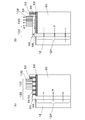
- FIG. 5 is a cross-sectional view taken along the line BB of FIG. 3 showing the heat flow inside the fuel cell module 10 according to the first embodiment.
- FIG. 5A is a diagram showing a heat flow when the membrane electrode assembly 12 is lower than a predetermined temperature.
- FIG. 5B is a diagram showing a heat flow when the membrane electrode assembly 12 is at a predetermined temperature or higher.
- the boundary surface 56 is formed in the heat transfer section 122.
- the predetermined temperature is 40 to 50 ° C., for example. In this case, the heat applied to the heat pipe 50 is not released from the heat pipe 50. Therefore, the heat generated from the membrane electrode assembly 12 is transmitted to the fuel storage unit 60 (arrow P).
- the fuel cell module 10 when the fuel cell module 10 is started, heat is not released from the membrane electrode assembly 12 to the outside of the fuel cell module 10, and the fuel storage section 60 is transmitted by heat transfer from the membrane electrode assembly 12. Since the temperature of the fuel cell module 10 becomes higher, the fuel cell module 10 can be activated quickly. Further, during operation of the fuel cell module 10, the temperature of the membrane electrode assembly 12 and the fuel storage unit 60 can be maintained at an appropriate temperature without increasing more than necessary. Therefore, the temperature of the membrane electrode assembly 12 and the fuel storage unit 60 can be easily adjusted to an appropriate range.
- boundary surface 56 of the heat pipe 50 is adjusted in advance so as to move to a desired position in accordance with the temperature of the membrane electrode assembly 12 has been described.
- a sensor for measuring the temperature may be further provided, and the movement of the boundary surface 56 may be controlled based on a detection value by the sensor.
- FIG. 6 is a perspective view showing an appearance of the fuel cell module 10 according to Embodiment 2.
- FIG. 7 is a perspective view showing the external appearance of the structure inside the housing of the fuel cell module 10 according to Embodiment 2.
- FIG. The fuel cell module 10 according to the second embodiment is the same as the first embodiment except that the arrangement is different from the membrane electrode assembly 12, the fuel storage unit 60, and the heat pipe 50. Therefore, for the fuel cell module according to Embodiment 2, description of the same configuration as in Embodiment 1 will be omitted as appropriate.
- the fuel cell module 10 has a structure in which a fuel accommodating portion 60 is laminated adjacently on the membrane electrode assembly 12.
- the membrane electrode assembly 12 and the fuel storage portion 60 are thermally connected adjacent to each other. Since the membrane electrode assembly 12 that needs to take in air exists only on the lower side of the internal structure of the fuel cell module 10, the air intake 22 is provided only on the lower side of the housing 20 as shown in FIG. ing.
- the heat absorbing portion 124 of the heat pipe 50 that is a heat transfer means has a stacked membrane electrode assembly 12 and side surfaces of the fuel storage portion 60, that is, the membrane electrode assembly 12 and the fuel storage. In a surface substantially perpendicular to the contact surface with the portion 60, the two surfaces are thermally connected adjacent to each other.
- the heat transfer portion 122 and the second region 78 of the heat pipe 50 are disposed on the heat insulating material 62 laminated on the fuel storage portion 60 and thermally indirect with the membrane electrode assembly 12 and the fuel storage portion 60. Connected.
- FIG. 8 is a cross-sectional view taken along the line CC in FIG. 7 showing the heat flow inside the fuel cell module 10 according to the second embodiment.
- FIG. 8A is a diagram showing a heat flow when the membrane electrode assembly 12 is below a predetermined temperature.
- FIG. 8B is a diagram showing the flow of heat when the membrane electrode assembly 12 is at a predetermined temperature or higher.
- the boundary surface 56 is formed in the heat transfer section 122.
- the heat applied to the heat pipe 50 is not released from the heat pipe 50. Therefore, the heat generated from the membrane electrode assembly 12 is not released to the outside of the fuel cell module 10 but is transmitted to the fuel storage unit 60 (arrow P).
- the fuel container 60 is transmitted by heat transfer from the membrane electrode assembly 12. Since the temperature of the fuel cell module 10 becomes higher, the fuel cell module 10 can be activated quickly. Further, during operation of the fuel cell module 10, the temperature of the membrane electrode assembly 12 and the fuel storage unit 60 can be maintained at an appropriate temperature without increasing more than necessary. Therefore, the temperature of the membrane electrode assembly 12 and the fuel storage unit 60 can be easily adjusted to an appropriate range.
- a set of membrane electrode assemblies 12 is illustrated, and the fuel cell is a single cell, but there are a plurality of membrane electrode assemblies 12 in a planar shape. It is also possible to adopt a configuration in which a plurality of membrane electrode assemblies 12 are connected in series by an electrical connection member such as an interconnector, a current collector, and wiring.
- the fuel cell to which the present invention is applied may have a stack structure in which the membrane electrode assemblies 12 are stacked.
- the present invention can be used for fuel cells.
Landscapes
- Life Sciences & Earth Sciences (AREA)
- Engineering & Computer Science (AREA)
- Manufacturing & Machinery (AREA)
- Sustainable Development (AREA)
- Sustainable Energy (AREA)
- Chemical & Material Sciences (AREA)
- Chemical Kinetics & Catalysis (AREA)
- Electrochemistry (AREA)
- General Chemical & Material Sciences (AREA)
- Fuel Cell (AREA)
Abstract
燃料電池モジュール10の熱伝達手段50は、吸熱部124と、放熱部120と、吸熱部124と放熱部120との間に設けられ表面が断熱性を有する伝熱部122とを有し、吸熱部124において燃料電池12および燃料収容部60と熱的に接続されている。熱伝達手段50は、燃料電池12が所定温度未満の場合、熱伝達性を有する領域と熱伝達を抑制する領域との境界面が伝熱部122に形成されることにより、燃料電池12で発生した熱を燃料収容部60に伝達し、燃料電池12が所定温度以上の場合、熱伝達性を有する領域と熱伝達を抑制する領域との境界面56が放熱部120に形成されることにより、燃料電池12および燃料収容部60で発生した熱を、吸熱部124および伝熱部122を介して、放熱部120から燃料電池12および燃料収容部60の外に放出する。
Description
本発明は燃料電池モジュールに関する。
燃料電池は水素と酸素とから電気エネルギーを発生させる装置であり、高い発電効率を得ることができる。燃料電池の主な特徴としては、従来の発電方式のように熱エネルギーや運動エネルギーの過程を経ない直接発電であるので、小規模でも高い発電効率が期待できること、窒素化合物等の排出が少なく、騒音や振動も小さいので環境性が良いことなどが挙げられる。このように、燃料電池は燃料のもつ化学エネルギーを有効に利用でき、環境にやさしい特性を持っているので、21世紀を担うエネルギー供給システムとして期待され、宇宙用から自動車用、携帯機器用まで、大規模発電から小規模発電まで、種々の用途に使用できる将来有望な新しい発電システムとして注目され、実用化に向けて技術開発が本格化している。
中でも、固体高分子形燃料電池は、他の種類の燃料電池に比べて、作動温度が低く、高い出力密度を持つ特徴が有り、特に近年、携帯機器(携帯電話、ノート型パーソナルコンピュータ、PDA、MP3プレーヤ、デジタルカメラあるいは電子辞書、電子書籍)などの電源への利用が期待されている。携帯機器用の固体高分子形燃料電池としては、複数の単セルを平面状に配列した平面配列型の燃料電池が知られている(特許文献1参照)。燃料としては、特許文献1に示したメタノールの他、水素吸蔵合金や水素ボンベに格納された水素を利用することが研究されている。
一般に燃料電池では、セル温度が高すぎると電解質膜が乾燥するドライアウトと呼ばれる現象が生じ、逆に、セル温度が低すぎると水が凝縮するフラッディングと呼ばれる現象が生じることにより発電性能が低下する。特にドライアウトに対する対策として、ヒートパイプを用いてセル温度を低下させる技術が知られている。しかし、従来の技術では、用いるヒートパイプの種類や、セル、燃料収容部、およびヒートパイプの配置が不適切であったため、熱の調節が不十分であった。
たとえば特許文献2には、ヒートパイプを内蔵する燃料電池が開示されている。また、特許文献3には、不活性ガスを封入し、一定温度以上にすると冷却効果が発現する構造を有するヒートパイプを用いた燃料電池が開示されている。
図9に、これら従来技術の問題点を模式的に示す。従来技術では、熱伝達手段であるヒートパイプ50の両端側にそれぞれ放熱手段130および燃料収容部60を配置し、ヒートパイプ50の入熱部に膜電極接合体12を配置していた。しかし、この場合、膜電極接合体12の温度にかかわらず膜電極接合体12から放熱が起きるため(矢印M)、膜電極接合体12が低温である燃料電池の起動時に発電性能が安定しないという問題があった。また、発電時においては、膜電極接合体12と燃料収容部60との間における熱の流れは一方向であるため(矢印N)、燃料収容部60を冷却することができない。そのため、膜電極接合体12による放熱が増大した場合、燃料収容部60の温度が上昇し過ぎてしまうという問題があった。
本発明はこうした課題に鑑みてなされたものであり、その目的は、燃料電池と燃料収容部の温度を適切に制御することができる燃料電池モジュールの提供にある。
本発明のある態様は、燃料電池モジュールである。当該燃料電池モジュールは、電解質膜と、電解質膜の一方の面に設けられたカソードと、電解質膜の他方の面に設けられたアノードとを含む燃料電池と、燃料電池に供給される水素を貯蔵する水素吸蔵合金を収容する燃料収容部と、燃料収容部から燃料電池に水素を供給するための水素供給経路と、吸熱性を有する吸熱部と、放熱性を有する放熱部と、吸熱部と放熱部との間に設けられ表面が断熱性を有する伝熱部とを有し、吸熱部において燃料電池および燃料収容部と熱的に接続された熱伝達手段と、を備えることを特徴とする。熱伝達手段は、燃料電池が所定温度未満の場合、熱伝達性を有する領域と熱伝達を抑制する領域との境界面が伝熱部に形成されることにより、燃料電池で発生した熱を燃料収容部に伝達し、燃料電池が所定温度以上の場合、熱伝達性を有する領域と熱伝達を抑制する領域との境界面が放熱部に形成されることにより、燃料電池および燃料収容部で発生した熱を、吸熱部および伝熱部を介して、放熱部から燃料電池および燃料収容部の外に放出する。
この態様によれば、燃料電池モジュールの起動時には膜電極接合体から燃料電池モジュールの外部に熱が放出されず、また膜電極接合体からの熱伝達により燃料収容部の温度が高くなるため、燃料電池モジュールを素早く起動させることができる。また、燃料電池モジュールの運転中には、膜電極接合体と燃料収容部との温度を必要以上に上昇させることなく、適切な温度に保つことができる。したがって、膜電極接合体と燃料収容部の温度を簡易に適切な範囲に調節することができる。
上記態様において、熱伝達手段は、熱を伝達する伝熱体が吸熱部側に位置し、熱の伝達を抑制する非伝熱体が放熱部側に位置することにより、伝熱体と非伝熱体とにより境界面が形成された筒状のヒートパイプであってもよい。境界面は、吸熱部から吸収された熱による伝熱体の温度の上昇に伴って、ヒートパイプの長さ方向に沿って吸熱部側から放熱部側に向かって移動してもよい。
また、放熱部の外面に取り付けられたヒートパイプ用放熱部材をさらに備えてもよい。この場合、燃料電池が所定温度になった場合に、境界面を含む平面がヒートパイプ用放熱部材の少なくとも一部を横断する位置まで、境界面が移動してもよい。
また、熱伝達手段の吸熱部は、燃料電池と燃料収容部との間に設けられ、放熱部は、吸熱部および伝熱部を介して燃料電池および燃料収容部と熱的に間接的に接続された位置に設けられていてもよい。
また、燃料電池は、燃料収容部と隣接して熱的に接続され、熱伝達手段の吸熱部は、燃料電池と燃料収容部との接触面に略垂直な面において、燃料電池の表面と燃料収容部の表面とに隣接して熱的に接続され、放熱部は、吸熱部および伝熱部を介して燃料電池および燃料収容部と熱的に間接的に接続された位置に設けられていてもよい。
また、水素供給経路には、熱を放出するための経路用放熱部材が設けられていてもよい。
本発明によれば、燃料電池と燃料収容部の温度を適切に制御することができる。
以下、本発明の実施の形態を図面を参照して説明する。なお、すべての図面において、同様な構成要素には同様の符号を付し、適宜説明を省略する。
図1は、実施の形態1に係る燃料電池モジュール10の外観を示す斜視図である。図2は、図1のA-A線に沿った断面図である。図3は、実施の形態1に係る燃料電池モジュール10の筐体20の内部における構造の外観を示す斜視図である。
燃料電池モジュール10は、筐体20と、筐体20に収容された膜電極接合体12、水素吸蔵合金タンクである燃料収容部60、ヒートパイプ50を主な構成として備える。なお、膜電極接合体12は、本明細書における「燃料電池」の一部または「燃料電池」そのものである。
筐体20には、膜電極接合体12のカソード側に対向する面(図1の前面、図2の下部)に複数の空気取入口22が設けられている。空気取入口22を通して、外部から筐体20の内部に酸化剤としての空気が流入可能である。また、図3に示すヒートパイプ用放熱部材132と近接する面(図1の上面)には、放熱口24が設けられている。放熱口24を通して、燃料電池モジュール10の内部で発生した熱を外部に放出可能である。
膜電極接合体12は、電解質膜30、カソード触媒層32およびアノード触媒層34を含む。
電解質膜30は、湿潤状態において良好なイオン伝導性を示すことが好ましく、カソード触媒層32とアノード触媒層34との間でプロトンを移動させるイオン交換膜として機能する。電解質膜30は、含フッ素重合体や非フッ素重合体等の固体高分子材料によって形成され、例えば、スルホン酸型パーフルオロカーボン重合体、ポリサルホン樹脂、ホスホン酸基又はカルボン酸基を有するパーフルオロカーボン重合体等を用いることができる。スルホン酸型パーフルオロカーボン重合体の例として、ナフィオン(デュポン社製:登録商標)112などが挙げられる。また、非フッ素重合体の例として、スルホン化された、芳香族ポリエーテルエーテルケトン、ポリスルホンなどが挙げられる。電解質膜30の厚さは、たとえば10~200μmである。
カソード触媒層32は、電解質膜30の一方の面に形成されている。カソード触媒層32には、外部から空気取入口22を経由して空気が供給される。また、アノード触媒層34は、電解質膜30の他方の面に形成されている。アノード触媒層34には、燃料収容部60から放出された水素が供給される。一対のカソード触媒層32とアノード触媒層34との間に電解質膜が30が狭持されることにより単セルが構成され、単セルは水素と空気中の酸素との電気化学反応により発電する。
カソード触媒層32およびアノード触媒層34は、それぞれイオン交換樹脂ならびに触媒粒子、場合によって炭素粒子を有する。
カソード触媒層32およびアノード触媒層34が有するイオン交換樹脂は、触媒粒子と電解質膜30とを接続し、両者間においてプロトンを伝達する役割を持つ。このイオン交換樹脂は、電解質膜30と同様の高分子材料から形成されてよい。触媒金属としては、Sc、Y、Ti、Zr、V、Nb、Fe、Co、Ni、Ru、Rh、Pd、Pt、Os、Ir、ランタノイド系列元素やアクチノイド系列の元素の中から選ばれる合金や単体が挙げられる。また触媒を担持する場合には炭素粒子として、ファーネスブラック、アセチレンブラック、ケッチェンブラック、カーボンナノチューブなどを用いてもよい。なお、カソード触媒層32およびアノード触媒層34の厚さは、それぞれ、たとえば10~40μmである。
ガスケット80は、カソード触媒層32の周囲に位置する電解質膜30(電解質膜30のカソード側の外周部)と筐体20のカソード側の内周側面に設けられたカソード側固定部材90との間に設けられている。ガスケット80により、燃料ガス室112から空気室110への燃料漏洩が防止される。
ガスケット82は、アノード触媒層34の周囲に位置する電解質膜30(電解質膜30のアノード側の外周部)と筐体20のアノード側の内周側面に設けられたアノード側固定部材92との間に設けられている。ガスケット82により、燃料ガス室112の密封性が高められ、燃料が漏洩することが抑制されている。
筐体20内にはアノード触媒層34と対向してシート状のガスシール部材40が設けられている。ガスシール部材40とアノード触媒層34との間には、水素が充填される空間となる燃料ガス室112が形成されている。ガスシール部材40により燃料ガス室112の密封性が高められている。ガスシール部材40は、水素の流出を遮断でき、且つ膜電極接合体12からの熱をヒートパイプ50に伝えることができる材料であればよく、たとえば、SUSやアルミニウム等の金属板が用いられる。ガスシール部材40は、「燃料電池」の一部である。ガスシール部材40と燃料収容部60との間には、ヒートパイプ50が配置されている。
水素吸蔵合金タンクである燃料収容部60は、膜電極接合体12のアノード側に対向する筐体20の内周面側に設けられている。燃料収容部60には、水素を吸蔵可能な水素吸蔵合金(たとえば、希土類系のMm(ミッシュメタル)Ni4.32Mn0.18Al0.1Fe0.1Co0.3)が格納されている。なお、水素吸蔵合金は、希土類系に限られず、たとえばTi-Mn系、Ti-Fe系、Ti-Zr系、Mg-Ni系、Zr-Mn系等であってもよい。
燃料収容部60の内部と燃料ガス室112とは、供給する水素の圧力調節機能を有する水素供給経路70を介して連通している。具体的には、水素供給経路70は、筐体20のアノード側の内周側面に沿って設けられており、燃料収容部60の側面において、レギュレータ71を介して水素供給経路70と燃料収容部60の内部とが連通している。レギュレータ71により、水素吸蔵合金から水素が放出される際に、燃料ガス室112に供給される水素の圧力が低減され、アノード触媒層34が保護される。また、燃料ガス室112の側面において、水素供給経路70と燃料ガス室112とを連通する水素供給口72が設けられている。
制御部100は、レギュレータ71の開度を制御することにより、燃料収容部60から燃料ガス室112に供給される水素の量を調節して燃料電池の出力を制御する。
L字状で筒状のヒートパイプ50の一方の辺は、ガスシール部材40と燃料収容部60との間に設けられており、ヒートパイプ50はガスシール部材40および燃料収容部60と熱的に接続している。ヒートパイプ50は、アノード触媒層34とは反対側のガスシール部材40の主表面、およびアノード触媒層34側の燃料収容部60の外周面に接していることが好ましい。これにより、ヒートパイプ50と、ガスシール部材40および燃料収容部60との間の熱の伝達性を高めることができる。ヒートパイプ50の構造や機能については後述する。
燃料電池モジュール10の筐体20の内部における構造を図3を用いて説明する。本実施の形態では、ヒートパイプ50の後述する吸熱部124が、膜電極接合体12と燃料収容部60との間に設けられ、両者に熱的に接続されている。また、ヒートパイプ50の後述する伝熱部122、放熱部120、およびガス溜め部52は、燃料収容部60の上部に設けられた熱を伝達しない断熱材62の上に配置され、膜電極接合体12および燃料収容部60と熱的に間接的に接続されている。ヒートパイプ50の第2領域78の端部には、ガス溜め部52が形成されている。ヒートパイプ50の第2領域78の放熱部120の上には、ヒートパイプ50から熱を放出するための複数のヒートパイプ用放熱部材132が設けられている。ヒートパイプ用放熱部材132は、アルミニウムなどの放熱効率の高い金属により形成されている。
また、膜電極接合体12と燃料収容部60の側面に設けられ、両者を接続する水素供給経路70の上部には、水素供給経路70を冷却するための経路用放熱部材74が設けられている。これにより、水素供給経路70が高温になりすぎることを防ぎ、水素供給経路70の部品の劣化を防ぐことができる。また、水素供給経路70の音鳴りを防止することができる。
図4は、実施の形態1に用いるヒートパイプ50の作動原理を説明するための概略図である。ここでは、説明を容易にするために、ヒートパイプ50を直線状のパイプとして説明する。図4(A)は、熱を加えない通常状態におけるヒートパイプ50を示す。ヒートパイプ50は、第1領域76と第2領域78とを有する。第1領域76には、一方の端部側から順に、熱を外部から内部に吸収可能な吸熱部124と、表面が断熱性を有し、熱の放出が抑制される伝熱部122とが形成されている。ヒートパイプ50の第2領域78には、伝熱部122の側から順に、熱を内部から外部に放出可能な放熱部120と、内部に収容されたガスを溜めることができるガス溜め部52とが形成されている。図3に示したヒートパイプ用放熱部材132は、放熱部120にてヒートパイプ50の外面に設けられている。ヒートパイプ50の第1領域76の吸熱部側には、熱を伝達する液体である伝熱体58が封入されている。また、第2領域78から第1領域76にかけて、熱の伝達を抑制する不凝縮性ガスである非伝熱体54が封入されている。伝熱体58と非伝熱体54とは、ヒートパイプ50の長さ方向に垂直に、境界面56を形成している。燃料電池モジュール10の停止状態では、境界面56は伝熱部122に形成されている。
ヒートパイプ50の材料としては、伝熱体58とは反応しないものが好ましく、例えば銅、ステンレス、アルミニウムなどの金属が挙げられる。また、伝熱体58としては、水、アンモニア、アルコール類などが好ましい。非伝熱体54としては、ヘリウム、窒素、ネオン、アルゴンなどの不活性ガスが好ましい。
図4(B)に示すように、燃料電池モジュール10の運転開始後、膜電極接合体12から生じた熱がヒートパイプ50に加わった場合、伝熱体58の一部が蒸発することにより、境界面56がヒートパイプ50の長さ方向に沿って第2領域78の方向に移動する。境界面56が伝熱部122に存在するときには、熱はヒートパイプ50から放出されない。ヒートパイプ50に熱がさらに加わり(矢印P)、境界面56が矢印Rの方向に移動し、放熱部120に到達したときに、放熱部120から熱が放出される(矢印Q)。なお、伝熱体58の内部では、熱により矢印Sで示す還流が生じている。
ヒートパイプ50にさらに熱が加わった場合、図4(C)に示すように、境界面56は、境界面56を含む平面がヒートパイプ50の放熱部120の外面に形成されたヒートパイプ用放熱部材132の少なくとも一部を横断する位置まで移動する。この場合、伝熱体58がヒートパイプ用放熱部材132と面することになるため、放熱部120から効率的に熱が放出される(矢印Q)。
図5は、実施の形態1に係る燃料電池モジュール10の内部における熱の流れを示す図3のB-B線に沿った断面図である。図5(A)は、膜電極接合体12が所定温度未満の場合における熱の流れを示す図である。図5(B)は、膜電極接合体12が所定温度以上の場合における熱の流れを示す図である。
図5(A)に示すように、膜電極接合体12が所定温度未満の場合、境界面56は伝熱部122に形成されている。所定温度とは例えば40~50℃である。この場合、ヒートパイプ50に加わった熱は、ヒートパイプ50から放出されない。そのため、膜電極接合体12から生成された熱は、燃料収容部60に伝達される(矢印P)。
図5(B)に示すように、膜電極接合体12が所定温度以上の場合、ヒートパイプ50にさらに熱が加わることにより(矢印P、R)、境界面56を含む平面がヒートパイプ用放熱部材132を横断してガス溜め部52の付近まで移動する。これにより、ヒートパイプ50の放熱部120の外面に形成されたヒートパイプ用放熱部材132を通じて、熱が放出される(矢印S)。この場合、伝熱体58の内部における熱の移動は、矢印Rの方向が主となるため、膜電極接合体12から燃料収容部60へは必要以上に熱が伝わることはない。
以上、本実施の形態によると、燃料電池モジュール10の起動時には膜電極接合体12から燃料電池モジュール10の外部に熱が放出されず、また膜電極接合体12からの熱伝達により燃料収容部60の温度が高くなるため、燃料電池モジュール10を素早く起動させることができる。また、燃料電池モジュール10の運転中には、膜電極接合体12と燃料収容部60との温度を、必要以上に上昇させることなく、適切な温度に保つことができる。したがって、膜電極接合体12と燃料収容部60の温度を簡易に適切な範囲に調節することができる。
なお、本実施の形態では、膜電極接合体12の温度に応じてヒートパイプ50の境界面56が所望の位置に移動するようにあらかじめ調整しておく場合を示したが、膜電極接合体12の温度を測定するセンサをさらに設け、当該センサによる検出値に基づいて境界面56の移動を制御してもよい。
(実施の形態2)
図6は、実施の形態2に係る燃料電池モジュール10の外観を示す斜視図である。図7は、実施の形態2に係る燃料電池モジュール10の筐体内部の構造の外観を示す斜視図である。実施の形態2に係る燃料電池モジュール10は、膜電極接合体12、燃料収容部60、およびヒートパイプ50と配置が異なる以外は、実施の形態1と同様である。そのため、実施の形態2に係る燃料電池モジュールについて、実施の形態1と同様な構成については適宜説明を省略する。
図6は、実施の形態2に係る燃料電池モジュール10の外観を示す斜視図である。図7は、実施の形態2に係る燃料電池モジュール10の筐体内部の構造の外観を示す斜視図である。実施の形態2に係る燃料電池モジュール10は、膜電極接合体12、燃料収容部60、およびヒートパイプ50と配置が異なる以外は、実施の形態1と同様である。そのため、実施の形態2に係る燃料電池モジュールについて、実施の形態1と同様な構成については適宜説明を省略する。
図7に示すように、実施の形態2に係る燃料電池モジュール10では、膜電極接合体12の上に燃料収容部60が隣接して積層された構造である。膜電極接合体12と燃料収容部60とは、隣接して熱的に接続されている。空気の取り込みが必要な膜電極接合体12が燃料電池モジュール10の内部構造の下側にしか存在しないため、図6に示すように、空気取入口22は筐体20の下側にのみ設けられている。
また、熱伝達手段であるヒートパイプ50の吸熱部124は、図7の右側に示すように、積まれた膜電極接合体12と燃料収容部60の側面、つまり膜電極接合体12と燃料収容部60との接触面に略垂直な面において、両者の表面に隣接して熱的に接続されている。ヒートパイプ50の伝熱部122と第2領域78とは、燃料収容部60の上に積層された断熱材62の上に配置され、膜電極接合体12および燃料収容部60と熱的に間接的に接続されている。
図8は、実施の形態2に係る燃料電池モジュール10の内部における熱の流れを示す図7のC-C線に沿った断面図である。図8(A)は、膜電極接合体12が所定温度未満の場合における熱の流れを示す図である。図8(B)は、膜電極接合体12が所定温度以上の場合における熱の流れを示す図である。
図8(A)に示すように、膜電極接合体12が所定温度未満の場合、境界面56は伝熱部122に形成されている。この場合、ヒートパイプ50に加わった熱は、ヒートパイプ50から放出されない。そのため、膜電極接合体12から生成された熱は、燃料電池モジュール10の外には放出されず、燃料収容部60に伝達される(矢印P)。
図7(B)に示すように、膜電極接合体12が所定温度以上の場合、ヒートパイプ50にさらに熱が加わることにより(矢印P、R、T)、境界面56を含む平面がヒートパイプ用放熱部材132を横断してガス溜め部52の付近まで移動する。これにより、ヒートパイプ50の放熱部120の外面に形成されたヒートパイプ用放熱部材132を通じて、熱が放出される(矢印S)。この場合、膜電極接合体12から燃料収容部60に伝達される熱の大部分は、矢印Tに示すように、ヒートパイプ50へと放出されるため、燃料収容部60が必要以上に加熱されない。
以上、本実施の形態によっても、燃料電池モジュール10の起動時には膜電極接合体12から燃料電池モジュール10の外部に熱が放出されず、また膜電極接合体12からの熱伝達により燃料収容部60の温度が高くなるため、燃料電池モジュール10を素早く起動させることができる。また、燃料電池モジュール10の運転中には、膜電極接合体12と燃料収容部60との温度を、必要以上に上昇させることなく、適切な温度に保つことができる。したがって、膜電極接合体12と燃料収容部60の温度を簡易に適切な範囲に調節することができる。
本発明は、上述の各実施の形態に限定されるものではなく、当業者の知識に基づいて各種の設計変更等の変形を加えることも可能であり、そのような変形が加えられた実施の形態も本発明の範囲に含まれうるものである。
例えば、上述の各実施の形態の燃料電池モジュール10では、一組の膜電極接合体12が例示されており、燃料電池は単セルとなっているが、膜電極接合体12が平面状に複数配設され、インターコネクタ、集電体、配線などの電気接続部材により複数の膜電極接合体12が直列に接続された構成も取り得る。また、本発明が適用される燃料電池は、膜電極接合体12が積層されたスタック構造を有してもよい。
10 燃料電池モジュール、12 膜電極接合体、20 筐体、22 空気取入口、24 放熱口、30 電解質膜、32 カソード触媒層、34 アノード触媒層、50 ヒートパイプ、54 非伝熱体、56 境界面、58 伝熱体、60 燃料収容部、70 水素供給経路、74 経路用放熱部材、76 一方の端部領域、78 他方の端部領域、80,82 ガスケット、100 制御部、110 空気室、112 燃料ガス室、120 放熱部、122 断熱部、124 入熱部、132 ヒートパイプ用放熱部材
本発明は、燃料電池に利用することができる。
Claims (6)
- 電解質膜と、前記電解質膜の一方の面に設けられたカソードと、前記電解質膜の他方の面に設けられたアノードとを含む燃料電池と、
前記燃料電池に供給される水素を貯蔵する水素吸蔵合金を収容する燃料収容部と、
前記燃料収容部から前記燃料電池に水素を供給するための水素供給経路と、
吸熱性を有する吸熱部と、放熱性を有する放熱部と、前記吸熱部と前記放熱部との間に設けられ表面が断熱性を有する伝熱部とを有し、前記吸熱部において前記燃料電池および前記燃料収容部と熱的に接続された熱伝達手段と、を備え、
前記熱伝達手段は、前記燃料電池が所定温度未満の場合、熱伝達性を有する領域と熱伝達を抑制する領域との境界面が前記伝熱部に形成されることにより、前記燃料電池で発生した熱を前記燃料収容部に伝達し、前記燃料電池が所定温度以上の場合、熱伝達性を有する領域と熱伝達を抑制する領域との境界面が前記放熱部に形成されることにより、前記燃料電池および前記燃料収容部で発生した熱を、前記吸熱部および前記伝熱部を介して、前記放熱部から前記燃料電池および前記燃料収容部の外に放出することを特徴とする燃料電池モジュール。 - 前記熱伝達手段は、熱を伝達する伝熱体が前記吸熱部側に位置し、熱の伝達を抑制する非伝熱体が前記放熱部側に位置することにより、前記伝熱体と前記非伝熱体とにより前記境界面が形成された筒状のヒートパイプであって、
前記境界面は、前記吸熱部から吸収された熱による前記伝熱体の温度の上昇に伴って、前記ヒートパイプの長さ方向に沿って前記吸熱部側から前記放熱部側に向かって移動することを特徴とする請求項1に記載の燃料電池モジュール。 - 前記放熱部の外面に取り付けられたヒートパイプ用放熱部材をさらに備え、
前記燃料電池が前記所定温度になった場合に、前記境界面を含む平面が前記ヒートパイプ用放熱部材の少なくとも一部を横断する位置まで、前記境界面が移動することを特徴とする請求項2に記載の燃料電池モジュール。 - 前記熱伝達手段の前記吸熱部は、前記燃料電池と前記燃料収容部との間に設けられ、前記放熱部は、前記吸熱部と前記伝熱部とを介して前記燃料電池および前記燃料収容部と熱的に間接的に接続された位置に設けられていることを特徴とする請求項1~3のいずれか1項に記載の燃料電池モジュール。
- 前記燃料電池は、前記燃料収容部と隣接して熱的に接続され、
前記熱伝達手段の前記吸熱部は、前記燃料電池と前記燃料収容部との接触面に略垂直な面において、前記燃料電池の表面と前記燃料収容部の表面とに隣接して熱的に接続され、
前記放熱部は、前記吸熱部および前記伝熱部を介して前記燃料電池および前記燃料収容部と熱的に間接的に接続された位置に設けられていることを特徴とする請求項1~3のいずれか1項に記載の燃料電池モジュール。 - 前記水素供給経路には、熱を放出するための経路用放熱部材が設けられていることを特徴とする請求項1~5のいずれか1項に記載の燃料電池モジュール。
Applications Claiming Priority (2)
| Application Number | Priority Date | Filing Date | Title |
|---|---|---|---|
| JP2011074202A JP2014112465A (ja) | 2011-03-30 | 2011-03-30 | 燃料電池モジュール |
| JP2011-074202 | 2011-03-30 |
Publications (1)
| Publication Number | Publication Date |
|---|---|
| WO2012132428A1 true WO2012132428A1 (ja) | 2012-10-04 |
Family
ID=46930202
Family Applications (1)
| Application Number | Title | Priority Date | Filing Date |
|---|---|---|---|
| PCT/JP2012/002149 Ceased WO2012132428A1 (ja) | 2011-03-30 | 2012-03-28 | 燃料電池モジュール |
Country Status (2)
| Country | Link |
|---|---|
| JP (1) | JP2014112465A (ja) |
| WO (1) | WO2012132428A1 (ja) |
Citations (5)
| Publication number | Priority date | Publication date | Assignee | Title |
|---|---|---|---|---|
| JPH1064567A (ja) * | 1996-06-14 | 1998-03-06 | Matsushita Electric Ind Co Ltd | 燃料電池用水素供給システム及び携帯用電気機器 |
| JP2000353536A (ja) * | 1999-06-09 | 2000-12-19 | Nippon Telegr & Teleph Corp <Ntt> | 燃料電池及びその運転方法 |
| JP2001248934A (ja) * | 2000-03-03 | 2001-09-14 | Nissan Motor Co Ltd | 熱エネルギー分配装置 |
| JP2008010158A (ja) * | 2006-06-27 | 2008-01-17 | Canon Inc | 燃料電池及び燃料電池を備える電子機器 |
| JP2008147026A (ja) * | 2006-12-11 | 2008-06-26 | Hitachi Ltd | 固体酸化物形燃料電池 |
-
2011
- 2011-03-30 JP JP2011074202A patent/JP2014112465A/ja not_active Withdrawn
-
2012
- 2012-03-28 WO PCT/JP2012/002149 patent/WO2012132428A1/ja not_active Ceased
Patent Citations (5)
| Publication number | Priority date | Publication date | Assignee | Title |
|---|---|---|---|---|
| JPH1064567A (ja) * | 1996-06-14 | 1998-03-06 | Matsushita Electric Ind Co Ltd | 燃料電池用水素供給システム及び携帯用電気機器 |
| JP2000353536A (ja) * | 1999-06-09 | 2000-12-19 | Nippon Telegr & Teleph Corp <Ntt> | 燃料電池及びその運転方法 |
| JP2001248934A (ja) * | 2000-03-03 | 2001-09-14 | Nissan Motor Co Ltd | 熱エネルギー分配装置 |
| JP2008010158A (ja) * | 2006-06-27 | 2008-01-17 | Canon Inc | 燃料電池及び燃料電池を備える電子機器 |
| JP2008147026A (ja) * | 2006-12-11 | 2008-06-26 | Hitachi Ltd | 固体酸化物形燃料電池 |
Also Published As
| Publication number | Publication date |
|---|---|
| JP2014112465A (ja) | 2014-06-19 |
Similar Documents
| Publication | Publication Date | Title |
|---|---|---|
| CN101496215A (zh) | 燃料电池 | |
| JP6477681B2 (ja) | 燃料電池モジュールおよび燃料電池スタック | |
| Zhao et al. | Design of a novel self-breathing micro fuel cell stack with a silicon membrane based on the demand for portable charging power sources | |
| US20100248058A1 (en) | Fuel cell module | |
| Hashemi et al. | Experimental studying of the effect of active area on the performance of passive direct methanol fuel cell | |
| JP4950505B2 (ja) | 燃料電池スタック | |
| JP2008262752A (ja) | 燃料電池スタック及びその暖機方法 | |
| WO2013065083A1 (ja) | 燃料電池システム | |
| JP2014013733A (ja) | 燃料電池システム | |
| JP2011054301A (ja) | 複合膜、膜電極接合体、燃料電池、複合膜の作製方法および膜電極接合体の作製方法 | |
| JP2004281072A (ja) | 燃料電池発電装置 | |
| JP2014112465A (ja) | 燃料電池モジュール | |
| CN103956512A (zh) | 一种被动排热燃料电池堆 | |
| JP2015079562A (ja) | 燃料電池及び燃料電池システム | |
| JP2006032284A (ja) | 液体燃料電池 | |
| JP2014049345A (ja) | 燃料電池システム | |
| US20150188159A1 (en) | Fuel cell stack | |
| JP2015522203A (ja) | 燃料電池システムにおける温度制御 | |
| JP2008010158A (ja) | 燃料電池及び燃料電池を備える電子機器 | |
| JP2011096559A (ja) | 燃料電池モジュール | |
| JP2008059817A (ja) | 燃料電池のセル構造及び燃料電池スタック | |
| JP2013214484A (ja) | 燃料電池システム | |
| CN101209668A (zh) | 一种燃料电池轿车用的散热方法 | |
| JP4872390B2 (ja) | 燃料電池システム | |
| KR101107081B1 (ko) | 연료 전지용 스택과 이를 갖는 연료 전지 시스템 |
Legal Events
| Date | Code | Title | Description |
|---|---|---|---|
| 121 | Ep: the epo has been informed by wipo that ep was designated in this application |
Ref document number: 12765499 Country of ref document: EP Kind code of ref document: A1 |
|
| NENP | Non-entry into the national phase |
Ref country code: DE |
|
| 122 | Ep: pct application non-entry in european phase |
Ref document number: 12765499 Country of ref document: EP Kind code of ref document: A1 |
|
| NENP | Non-entry into the national phase |
Ref country code: JP |